EP3328233B1 - Device for treating the hair having a removable rocking pressing element - Google Patents
Device for treating the hair having a removable rocking pressing element Download PDFInfo
- Publication number
- EP3328233B1 EP3328233B1 EP16742324.3A EP16742324A EP3328233B1 EP 3328233 B1 EP3328233 B1 EP 3328233B1 EP 16742324 A EP16742324 A EP 16742324A EP 3328233 B1 EP3328233 B1 EP 3328233B1
- Authority
- EP
- European Patent Office
- Prior art keywords
- pressing element
- hair
- housing
- notably
- applicator member
- Prior art date
- Legal status (The legal status is an assumption and is not a legal conclusion. Google has not performed a legal analysis and makes no representation as to the accuracy of the status listed.)
- Active
Links
Images






Classifications
-
- A—HUMAN NECESSITIES
- A45—HAND OR TRAVELLING ARTICLES
- A45D—HAIRDRESSING OR SHAVING EQUIPMENT; EQUIPMENT FOR COSMETICS OR COSMETIC TREATMENTS, e.g. FOR MANICURING OR PEDICURING
- A45D19/00—Devices for washing the hair or the scalp; Similar devices for colouring the hair
- A45D19/16—Surface treatment of hair by steam, oil, or the like
-
- A—HUMAN NECESSITIES
- A45—HAND OR TRAVELLING ARTICLES
- A45D—HAIRDRESSING OR SHAVING EQUIPMENT; EQUIPMENT FOR COSMETICS OR COSMETIC TREATMENTS, e.g. FOR MANICURING OR PEDICURING
- A45D1/00—Curling-tongs, i.e. tongs for use when hot; Curling-irons, i.e. irons for use when hot; Accessories therefor
- A45D1/02—Curling-tongs, i.e. tongs for use when hot; Curling-irons, i.e. irons for use when hot; Accessories therefor with means for internal heating, e.g. by liquid fuel
- A45D1/04—Curling-tongs, i.e. tongs for use when hot; Curling-irons, i.e. irons for use when hot; Accessories therefor with means for internal heating, e.g. by liquid fuel by electricity
-
- A—HUMAN NECESSITIES
- A45—HAND OR TRAVELLING ARTICLES
- A45D—HAIRDRESSING OR SHAVING EQUIPMENT; EQUIPMENT FOR COSMETICS OR COSMETIC TREATMENTS, e.g. FOR MANICURING OR PEDICURING
- A45D1/00—Curling-tongs, i.e. tongs for use when hot; Curling-irons, i.e. irons for use when hot; Accessories therefor
- A45D1/06—Curling-tongs, i.e. tongs for use when hot; Curling-irons, i.e. irons for use when hot; Accessories therefor with two or more jaws
-
- A—HUMAN NECESSITIES
- A45—HAND OR TRAVELLING ARTICLES
- A45D—HAIRDRESSING OR SHAVING EQUIPMENT; EQUIPMENT FOR COSMETICS OR COSMETIC TREATMENTS, e.g. FOR MANICURING OR PEDICURING
- A45D1/00—Curling-tongs, i.e. tongs for use when hot; Curling-irons, i.e. irons for use when hot; Accessories therefor
- A45D1/18—Curling-tongs, i.e. tongs for use when hot; Curling-irons, i.e. irons for use when hot; Accessories therefor with combs
-
- A—HUMAN NECESSITIES
- A45—HAND OR TRAVELLING ARTICLES
- A45D—HAIRDRESSING OR SHAVING EQUIPMENT; EQUIPMENT FOR COSMETICS OR COSMETIC TREATMENTS, e.g. FOR MANICURING OR PEDICURING
- A45D2/00—Hair-curling or hair-waving appliances ; Appliances for hair dressing treatment not otherwise provided for
- A45D2/001—Hair straightening appliances
-
- A—HUMAN NECESSITIES
- A45—HAND OR TRAVELLING ARTICLES
- A45D—HAIRDRESSING OR SHAVING EQUIPMENT; EQUIPMENT FOR COSMETICS OR COSMETIC TREATMENTS, e.g. FOR MANICURING OR PEDICURING
- A45D2/00—Hair-curling or hair-waving appliances ; Appliances for hair dressing treatment not otherwise provided for
- A45D2/001—Hair straightening appliances
- A45D2/002—Hair straightening appliances with combs
-
- A—HUMAN NECESSITIES
- A45—HAND OR TRAVELLING ARTICLES
- A45D—HAIRDRESSING OR SHAVING EQUIPMENT; EQUIPMENT FOR COSMETICS OR COSMETIC TREATMENTS, e.g. FOR MANICURING OR PEDICURING
- A45D34/00—Containers or accessories specially adapted for handling liquid toiletry or cosmetic substances, e.g. perfumes
- A45D2034/005—Containers or accessories specially adapted for handling liquid toiletry or cosmetic substances, e.g. perfumes with a cartridge
Definitions
- the present invention relates to devices for treating the hair, and more particularly, but not exclusively, those intended for shaping the hair, notably those intended for straightening, curling or crimping the hair.
- the invention is concerned with devices comprising two arms that are able to move with respect to one another, being able to take up a spaced-apart configuration for introducing a lock of hair between said arms and a moved-together configuration for treating the lock, the arms being able to move along the lock in this moved-together configuration.
- the arms frequently carry two heating elements with which the hair is brought into contact during the use of the device.
- the application WO 2009/078046 describes an appliance comprising a seat for accommodating a hair treatment device allowing a haircare product to be dispensed during operation.
- This device is composed of a support material impregnated with the haircare product for a single use. In the closed position, the support material comes into contact with a presser in the form of a roller or plate.
- the application WO 2014/064660 discloses a hairstyling appliance comprising a reservoir containing the product to be applied, an applicator member for applying said product on one of the jaws and a steam outlet on the other of the jaws.
- the applicator member is disposed opposite a counter-bearing surface.
- hairstyling appliances comprising heating elements that are each mounted in an articulated manner on a holding means.
- the invention aims to further improve devices for applying a haircare product to hair.
- a device for treating the hair comprising:
- rock should be understood as meaning that the pressing element can exhibit a rotary movement about at least one axis, it being possible for the movement of the pressing element to be a more complex movement, with rotary components about several axes, notably about or parallel to the longitudinal axis of the pressing element and/or about or parallel to a transverse axis of the housing.
- the pressing element makes it possible to push the hair against the applicator member so as to allow effective application of the cosmetic product onto the hair.
- the rocking of the pressing element makes it possible to exert a more uniform pressure along the entire length of the applicator member and to take account of manufacturing tolerances.
- the pressing element is able to adapt to a possible incorrect inclination of the applicator member, this being particularly useful when the applicator member is removable and can come from various sources.
- the pressing element is removable makes it possible to clean the latter, notably after a lengthy use or when the user wishes to change the cosmetic product to be applied.
- This also makes it possible to change the pressing element, notably to replace it with a pressing element with a different shape, or with a different size, in order for example to modify the quantity of cosmetic product applied and/or the effect obtained on the hair, notably by modifying the force with which the pressing element presses against the applicator member.
- This also makes it possible to access the housing which holds it and to be able to clean the latter and/or change the support means. For example, in the case of a spring disposed in the housing, this can make it possible to change the latter notably in order to modify the pressure exerted on the applicator member by the pressing element.
- the pressing element and the applicator member each have an elongate shape along a longitudinal axis Y and are advantageously the same length.
- the pressing element has a bearing surface having a shape complementary to that of the application surface of the applicator member.
- the bearing surface and the application surface are flat in their opposing regions.
- the support member can be rigid; alternatively, it is elastically deformable.
- the support means comprises a region in which contact is made rigidly and one or more regions in which contact is made with one or more elastic return members which are designed for example to return the pressing element into a predefined rest position when there is no mechanical loading by the applicator member.
- the elastic return member(s) can be coil springs or leaf springs.
- the support means comprises, notably is, a relief protruding from the bottom of the housing and/or of the pressing element, notably in the form of a half-sphere, or in the form of a substantially conical tooth, or in the form of a half-cylinder oriented perpendicularly to the longitudinal axis of the pressing element.
- the support means comprises at least one spring, notably a leaf spring, disposed in the housing, for example fastened to the bottom of the housing or fastened to the pressing element.
- the spring(s) force(s) the pressing element into abutment against the protruding relief.
- the spring(s) can force the pressing element into abutment against the relief protruding from the bottom of the housing.
- the support means can be removable, being held for example in a depression in the housing when it is in place on the device.
- a small extent of the bearing zone facilitates the rocking.
- the bearing region in the housing is situated substantially half-way along the pressing element.
- the support means comprises at least two springs, notably two coil springs that are disposed in the housing, fastened to the bottom of the housing or fastened to the pressing element, and are disposed notably close to the axial ends of the pressing element. It is then possible for the pressing element to rock on account of the elastically deformable nature of the springs.
- the housing is preferably closed over at least three of its sides and over its bottom.
- the pressing element is preferably inserted, notably by being slid, into the housing or withdrawn therefrom through a front opening in the latter.
- the pressing element may comprise at least one relief such as a rib or a groove that cooperates with a complementary relief such as a groove or a rib on an opposing wall of the device, at least partially defining the housing.
- the device may comprise, on the second arm, at least one member for locking the pressing element in the housing, notably a locking member intended to cooperate with the pressing element, in particular with a corresponding relief on the latter.
- the locking member makes it possible to prevent the pressing element from accidentally coming out.
- the pressing element may be able to move along an axis perpendicular to the application surface, notably able to move over a maximum depression travel of between 5 mm and 1 mm.
- the abovementioned grooves are wider than the corresponding ribs, such that the pressing element is able to move in translation relative to the ribs, and thus to the housing, along this axis.
- the maximum depression travel may be defined by a relief on the pressing element, coming into contact with the bottom of the housing, and/or by the width of the grooves.
- the travel of the pressing element may notably be such that, while the device is being used, the hairs to be treated, which are held between the two arms of the device, are aligned, and preferably extend parallel to a direction of movement of the device.
- the pressing element can form a one-piece part.
- the pressing element can have a flat or non-flat bearing surface, notably having in cross section a contour that is not straight, for example convex or concave towards the outside, in the form of a dihedron or of a dihedron truncated at its top.
- the pressing element can have a substantially parallelepipedal shape or be formed by a roller.
- the pressing element can have surface roughness.
- the roughness can notably help to straighten the hair.
- the pressing element can be made of a plastics material, notably of polyamide (PA), glass-fibre reinforced polyamide (PAGF) or polybutylene terephthalate (PBT), or of metal.
- PA polyamide
- PAGF glass-fibre reinforced polyamide
- PBT polybutylene terephthalate
- the pressing element is made of a porous material, notably a material formed by fibres that are oriented substantially in the same direction and assembled to form a felt, or of a foam.
- the pressing element can help to apply the product to both sides of the treated lock, and/or to absorb surplus product, and/or to homogenize the application of the product to the hair.
- the pressing element can be heated. This can make it possible, at the time that the cosmetic product is applied, to fluidize the latter.
- the pressing element can have a length of between 70 mm and 110 mm.
- the applicator member is preferably made of a porous material, notably formed by a set of fibres that are oriented substantially in the same direction and assembled to form a felt, or of a foam.
- the applicator member can have a flat or non-flat bearing surface, notably having in cross section a side with a contour that is not straight, for example convex or concave towards the outside.
- the applicator member is saturated with the cosmetic product to be applied to the hair.
- the pressing element comprises at least one protuberance or pin inserted into a path defined by the housing holding the pressing element. This protuberance or pin defines a rocking axis of the pressing element.
- the path is defined for example by a slot or a groove.
- This protuberance can be carried by an elastically deformable tab of the pressing element.
- the protuberance can be fitted in this path by elastic deformation of the tab that carries it, during the mounting of the pressing element in the housing.
- the pressing element comprises two such tabs and two such protuberances, which face one another.
- the pressing element can be urged into the spaced-apart position by two springs, notably coil springs working in compression, that are held at one end in guides and bear at the other end against a wall of the pressing element.
- the housing can have a relief, notably with a T-shaped cross section, and the pressing element can be retained in the housing by reliefs of the pressing element, notably bulges, coming into abutment under the head of the T.
- the comb can be fastened by being slid on the pressing element, by insertion of at least two mutually separate fastening reliefs into corresponding housings in the pressing element, which are likewise mutually separate.
- the fastening reliefs can be ribs having a cylindrical shape with an at least partially circular cross section, and can be connected to the rest of the comb by lugs which are inserted into corresponding slots, through which the housings open onto the outside.
- the fastening reliefs are hooks that are inserted into windows in the pressing element.
- the pressing element can have a U-shaped overall cross section with two opposite uprights, and the disposition of ribs and housings is preferably such that the comb is pressed against one of the uprights of the pressing element, the base of the teeth of the comb being positioned substantially at the wall connecting the uprights, which also defines the bearing surface for the applicator member.
- the comb can have a longitudinal rib that bears against said upright, above the abovementioned lugs that connect the cylindrical ribs to the rest of the comb.
- the comb also bears frontally against the upright below said lugs.
- the comb may comprise an elastically deformable locking tab designed to be snap-fastened to the pressing element once it has finished being introduced into the latter.
- the comb may comprise blocking reliefs on the fastening reliefs that cooperate with complementary blocking reliefs on the pressing element.
- the comb may comprise a blocking tab that closes the introduction opening once the comb has been mounted on the pressing element.
- the comb may comprise a handle which helps it to be fitted and removed.
- the comb can only be introduced into or removed from the pressing element when the latter is in its high position.
- the walls defining the housings for receiving the separate longitudinal ribs of the comb can be inserted into corresponding windows in the underlying structure when the pressing element is depressed, these windows being formed in a wall of the housing extending between the U-shaped uprights of the pressing element. When the pressing element is depressed, said wall tends to prevent the exit of the ribs of the comb that are inserted into said housings.
- the pressing element and the applicator member can be made of the same material.
- the applicator member is removable.
- the applicator member can be mounted on a part that serves as a holder in order to form a removable refill.
- the fact that the applicator member or the refill is removable makes it possible to change the applicator member for hygiene reasons or when it no longer contains any cosmetic product, or when the user wishes to use another applicator member or a different refill, notably with a different shape or containing a different cosmetic product.
- the applicator member can be supplied with product by a reservoir in the arm which carries it.
- This reservoir can be fastened permanently to the arm or be removable, and for example designed to be fitted and removed at the same time as the applicator member.
- the device may comprise at least two heated plates, which are disposed on the first and the second arm, respectively, and each press the hair against the other of the heated plates in the moved-together configuration.
- the pressing element preferably has a length substantially equal to the length of the heated plate(s).
- the device preferably comprises a detection member for recording the number of applications of product and/or the time for which the hair is pressed against the applicator member, for example the number of times the arms are moved together and/or the time for which they are held in the moved-together configuration.
- This detection member may comprise a switch, a reed switch, or an optical, inductive or capacitive sensor.
- This detection member is preferably disposed in the housing under the pressing element in order for the latter to come into contact therewith in the moved-together configuration of the arms.
- the device may comprise an identifier of the applicator member, notably of the refill, in particular a particular relief present on the refill or an electronic identification chip.
- the device may comprise a member for identifying the applicator member, which detects the identifier of the applicator member and compares it with registered identifiers. This can prevent the use of an applicator member that is not registered or allow the device to link a number of applications to the hair and/or an application time with each applicator member. Thus, when the applicator member is changed, the device recognizes the new applicator member.
- the device may comprise a steam outlet for exposing the hair introduced into the device to steam, notably a steam outlet disposed upstream of the applicator member, in the direction of movement of the device over the hair.
- a further subject of the invention is a method for treating hair with the aid of a device according to the invention, wherein the arms of the device are closed around a lock of hair and said device is moved along the lock of hair in order to expose the latter to the successive steps of:
- the method may also include the step(s) of:
- Figure 1 shows the handpiece 2 of an example of a device for treating the hair according to the invention.
- This handpiece 2 has two jaws 3 and 4 that are able to move with respect to one another between a spaced-apart configuration (not shown) for the introduction between said jaws of a lock of hair, and a moved-together configuration for treatment, illustrated in Figure 1 .
- the jaws 3 and 4 are carried by an upper arm 5 and a lower arm 6, respectively, which, in the example in question, are connected together at one end by an articulation 8, the handpiece 2 thus forming tongs.
- the upper arm 5 and lower arm 6 each preferably have a total length of between 22 cm and 31 cm and define, between the articulation 8 and the jaws 3 and 4, respective half-handles 10 and 11 on which the user can press in order to move the jaws 3 and 4 together.
- the upper arm 5 and lower arm 6 extend along respective longitudinal axes X 1 and X 2 which are preferably substantially parallel to one another when the jaws 3 and 4 are closed.
- An elastic return member (not visible) is preferably provided to return the jaws 3 and 4 to a spaced-apart configuration, this elastic return member being for example a spring disposed around an articulation pin 8.
- the invention is not limited to a particular manner of connecting the upper arm 5 and lower arm 6 together and the jaws 3 and 4 may be rendered able to move in some other way without departing from the scope of the present invention.
- the presence of an articulation is largely preferred for the ergonomics it provides.
- the jaws 3 and 4 define between one another a region for treating the hair, said region being intended to receive a lock of hair to be treated, the handpiece 2 being moved along said lock during the treatment, for example in the direction from the root to the end of the hair.
- the handpiece 2 is configured to comb the hair by passing it through a comb 13, to apply a cosmetic product, to treat the hair by way of steam and then to carry out a heat treatment of the hair by contact with two heating surfaces 15, 16, formed in this case by heated plates intended to heat the hair.
- the direction D of movement of the handpiece 2 over the hair is preferably substantially perpendicular to the longitudinal axes X 1 and X 2 of the arms 5 and 6.
- the handpiece 2 is connected by a line 18 to a base station (not shown) that is fixed during the treatment and is connected to the mains.
- This base station provides the electric power supply to the handpiece 2 and also its supply with water in order to generate steam, and may also carry out additional functions of processing electrical signals received from the handpiece 2.
- the line 18 which connects the handpiece 2 to the base station can thus comprise various electrical conductors and a water supply pipe.
- a user interface (not shown in the figures) can be present on the handpiece 2 so as to allow the user for example to start up certain components thereof, or not.
- the cosmetic product is applied by a refill 20 carried by one of the two arms, 5 or 6, in this case the upper arm 5.
- the refill 20 comes into contact with a pressing element 21 disposed opposite the latter.
- the refill 20 comprises a body 23 and an applicator member 26 that is held in the body 23 and has an application surface 36 that comes into contact with the hair present above the pressing element 21.
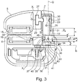
- the refill 20 can be fastened to the arm 5 or 6 by any means, notably, as illustrated in Figure 3 , by sliding a rib 27 of the body 23 into a groove 29 with a complementary shape.
- the body 23 has a cavity 30 that opens towards the outside by way of an opening 31 into which the applicator member 26 is inserted while the refill 20 is being manufactured.
- the body 23 comprises reliefs 32 for holding the applicator member 26 that extend into the cavity 30.
- the body 23 and the applicator member 26 have substantially the overall shape of a rectangular parallelepiped and are elongate along a longitudinal axis Z.
- the applicator member 26 is composed for example of fibres that are oriented substantially in the same direction, parallel to the axis Z, and are assembled to form a felt.
- the application surface 35 of the applicator member 26 may, as illustrated, be flat.
- the applicator member 26 can be produced by assembling two felts, notably with different densities.
- one of the felts can be composed of fibres which are oriented in one direction, notably parallel to the axis Z, and the other of the felts can be composed of fibres which are oriented in a direction perpendicular to the other fibres and notably perpendicular to the axis Z.
- the pressing element 21 has a bearing surface 36 which may have a shape complementary to the application surface 35.
- the bearing surface 36 can thus be flat, elongate along a longitudinal axis Y substantially parallel to the longitudinal axis Z in the moved-together position of the arms 5 and 6, and have substantially the same extent as the application surface 35.
- the pressing element 21 is housed removably in a housing 38 through a front opening in the latter.
- the housing 38 also opens outwards through at least one opening 37 facing the applicator member 26.
- the pressing element 21 is introduced into its housing 38 by ribs 45 on the housing 38 being slid into corresponding grooves 48 in the pressing element 21.
- the ribs 45 are disposed on opposite side walls 54 and 56 of the housing 38.
- the grooves 48 in the pressing element 21 are disposed on the side walls of the pressing element 21, which face the walls 54 and 56, respectively.
- the pressing element 21 is able to move along an axis Q perpendicular to the longitudinal axis Y, between a high position spaced apart from the bottom of the housing 38 and a low position moved together therewith.
- the pressing element 21 bears against a support means 40 that extends in the housing 38, allowing the pressing element 21 to carry out a rocking movement and, in the open position of the arms 5 and 6, keeping the pressing element 21 in the high position.
- the travel P of the pressing element between its high position and its low position is between 1 mm and 5 mm, for example equal to around 3 mm.
- the movement of the pressing element 21 is limited by the bottom 42 of the housing or by the width l of the groove 48.
- the travel of the pressing element advantageously makes it possible to position the pressing element, in the closed position of the device, such that the hairs are substantially aligned, that is to say without deviation of a lock of hair between the part situated between the heated plates and the part situated between the pressing element and the applicator member.
- the distance between the two heated plates is substantially equal to the distance between the pressing element and the applicator member, these two distances being measured in a direction substantially collinear with the axis Q.
- the bearing surface 36 of the pressing element is substantially coplanar with the heating surface 16, while the application surface 35 is substantially coplanar with the heating surface 15, in planes normal to the direction Q. This thus improves the straightening of the hair by the device.
- the support means 40 is a leaf spring fastened in a depression 41 in the pressing element 21, oriented towards the bottom 42 of the housing 38.
- the leaf spring 40 bears against the bottom 42 of the housing 38 in a region 43 about which the rocking of the pressing element 21 takes place about a rotation axis B substantially perpendicular to the axes Y and Q.
- the leaf spring 40 has fastening tabs 44 that come into contact with the pressing element 21 in the depression 41 and, therebetween, a portion 46 that is convex towards the bottom 42 of the housing 38, the central part of which defines the rocking region 43.
- the height s taken up by the leaf spring 40 prior to introduction into the housing 88 is greater than or equal to the distance f between the bottom of the housing 43 and the bottom of the depression 41.
- the distance f is for example between 1 mm and 5 mm, and for example equal to around 3 mm.
- the housing 38 is substantially the same length L as the pressing element 21.
- the length L of the pressing element 21 is for example between 70 mm and 110 mm, preferably 90 mm.
- the pressing element has a length substantially equal to the length of the heating surface(s).
- the grooves 48 have a width l greater than the thickness e of the ribs 45.
- the width l of the ribs 48 is for example between 1 mm and 5 mm, for example equal to around 3.2 mm.
- the thickness e of the grooves 45 is between 0.5 mm and 5 mm, in this case equal to 1 mm. Such a difference allows the pressing element 21 to move along the axis Y and/or to rock as described above.
- the two ribs 45 are offset along the axis Q by a distance d of for example between 1 mm and 5 mm, for example equal to around 2 mm.
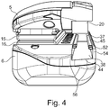
- the pressing element 21 is locked in the housing 38 by a protruding relief 50, visible in Figures 5 and 6 , that is present in the groove 48 in the pressing element 21 and which engages with a set-back relief 52, visible in Figure 4 , in the rib 45 of the housing 38.
- the relief 50 does not extend along the entire width l of the groove 48, and so, in order to remove the pressing element 21, it is sufficient to press on the latter such that it is depressed along the axis Q and the relief 50 detaches from the relief 52. It is thus possible to slide the pressing element 21 forwards in the housing 38.
- the comb 13 is situated upstream of the applicator member 26 and the pressing element 21 in the direction D of movement of the handpiece 2.
- the comb 13 is integral with the pressing element 21, preferably being moulded in one piece with the latter.
- the comb 13 extends parallel to the bearing surface 36 and along substantially the entire length thereof.
- the comb 13 has a plurality of teeth 55 that each extend along an axis parallel to the axis Q.
- the comb 13 advantageously has more than 20 teeth 55, better still more than 30 teeth 55, and in this case there are around 44 teeth.
- the base of the teeth 55 is set back with respect to the bearing surface 35, notably by a distance r of between 0.2 mm and 5 mm, for example equal to 2 mm. This allows the hair to be inserted properly between the bearing surface 36 and the application surface 35.
- the teeth 55 are preferably all the same height H , between 2 mm and 12 mm, for example equal to 8 mm. This height is sufficiently great to allow a proper hold of the hair between the teeth 55.
- the teeth 55 are all at equal distances from one another.
- the spacing k between the teeth 55 is preferably between 0.3 mm and 3 mm, for example equal to 1 mm.
- the pressing element 21 may comprise a relief such as a tongue 57 to make it easier to grasp.
- the handpiece 2 has a steam outlet 58 that is disposed on the arm 6 and is used after the cosmetic product has been applied to the hair.
- the user closes the two arms 5 and 6 around a lock of hair and moves the handpiece 2, in the closed position, from the root of the hair to the end of the latter.
- the hair is first of all combed by the comb 13, then product is applied by the hair being pressed against the applicator member 26 by the pressing element 21, and then the hair is subjected to steam by the steam outlet 58 and finally is heated between two heating surfaces 15 and 16.
- the example in Figures 7 and 8 differs from the one in Figures 1 to 6 in that the leaf spring 40 is fastened or positioned in the housing 38.
- the latter comprises for example a depression 60 that receives the leaf spring 40, where the latter is fastened by any suitable fastening means.
- the leaf spring 40 is then in contact with the bottom of the housing 42 by way of its ends 44 and its region of contact with the pressing element 21 defines a rocking region 43.
- the examples in Figures 9 and 10 differ from the one in Figures 1 to 6 in that the support means 40 is a relief protruding from the pressing element 21 or from the bottom 42 of the housing 38.
- the protruding relief 40 is a relief on the bottom 42 of the housing 38.
- the relief 40 has a substantially triangular shape, in section in a plane containing the longitudinal axis of the pressing element 21.
- the protruding relief 40 may notably have a semicircular or semi-polygonal shape.
- the protruding relief 40 may be in the form of a tooth which extends from the centre of the bottom 42 of the housing 38 and against which the pressing element 21 bears.
- the pressing element 21 can bear against the end of the tooth 40, which has a small extent. This allows the pressing element to rock about at least two different rotation axes, notably an axis parallel to the axis Y and the axis B.
- the protruding relief 40 can be in the form of a half-cylinder extending along an axis parallel to the axis B, and the pressing element 24 bears against a generatrix of the relief 40.
- the example in Figure 10 differs from the one in Figure 9 in that the protruding relief 40 belongs to the pressing element 21.
- the example in Figure 11 differs from the one in Figures 1 to 6 in that the support means 40 is a coil spring.
- the latter is interposed between the pressing element 21 and the bottom 42 of the housing 38.
- the pressing element 21 and the bottom of the housing 42 each comprise a depression 41 and 60, for keeping the coil spring 40 in position.
- the latter is disposed so as to bear against the centre of the pressing element 21.
- the example in Figure 12 differs from the one in Figure 11 in that the support means 40 comprises two coil springs 40a and 40b, each disposed close to one end of the pressing element 21.
- FIGS 13A to 13C illustrate variants of the bearing surface 36 of the pressing element 21.
- the bearing surface 36 can have a cross section that is curved, as illustrated in Figure 13A , in the form of a dihedron, as illustrated in Figure 13B , or in the form of a truncated dihedron, as illustrated in Figure 13C .
- the invention is not limited to such forms.
- the example in Figure 14 differs from the one in Figures 1 to 4 in that the comb 13 is mounted on the pressing element 21 in a removable manner.
- the comb 13 may comprise at least one groove 70, notably a T-shaped groove, intended to engage with a complementary rib 72 on the pressing element 21.
- the groove 70 makes it possible to keep the comb 13 on the pressing element 21.
- the comb 13 and/or the pressing element 21 may comprise a locking member (not illustrated) for preventing the comb from coming away freely from the pressing element 21.
- the comb 13 comprises a rib and the applicator member comprises a corresponding groove. Any other means of removable fastening is also possible.
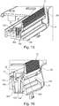
- Figures 15 to 21 illustrate another variant of a pressing element 21 on which a comb 13 is mounted in a removable manner.
- the pressing element 21 has, along at least a part of its length, a cross section with the overall shape of a U.
- the upper surface of the web of the U in this case forms the bearing surface 36.
- the two lateral uprights 101, 102 of the U have respective retaining bulges 103 and 104. These bulges are oriented towards one another and extend substantially in the longitudinal direction of the pressing element 21.
- the lower arm 6, holding the pressing element 21, has a protruding relief 105 with a T-shaped cross section, the head 160 of which is held between the uprights 101 and 102.
- the lower arm 6 also forms two housings for receiving respective springs 40a, 40b that are open towards the pressing element 21.
- Complementary guides for holding the coil springs 40a, 40b can be provided on the pressing element 21, notably in the region opposite the bearing surface 36.
- the pressing element 21 comprises tabs 157, one of which is visible in Figure 18 and which are each provided with facing protuberances 156. These protuberances 156 are intended to slide in grooves 155 in the relief 105, substantially half-way along the latter.
- the pressing element 21 can be mounted on the lower arm 6 as follows:
- the tabs 157 deform elastically so as to allow the protuberances 156 to be fitted in the grooves 155.
- the pressing element 21 forms a rib 106 that extends in the longitudinal direction thereof.
- the rib 106 is in this case oriented towards the outside of the device, when the pressing element 21 is mounted.
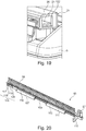
- a comb 13 that can be joined to the pressing element 21 is illustrated in Figures 20 and 21 .
- the comb 13 has in this case two cylindrical ribs 107, 108 that extend in the longitudinal direction of the comb 13, on one and the same side thereof.
- the cylindrical ribs 107, 108 each extend along only a part of the length of the comb 13, one after the other in the lengthwise direction of the comb 13.
- the two cylindrical ribs 107, 108 are connected to a web 109 of the comb 13 by two lugs 110, 111 that extend substantially perpendicularly to the teeth 55 of the comb.
- the comb 13 also has a blocking tab 115 which extends, as illustrated, perpendicularly to the longitudinal direction of the comb 13 and to the plane of the tongue 57.
- the tab 115 is provided in the vicinity of the end of the comb 13 having the tongue 57.
- the tab 115 is situated, in the lengthwise direction of the comb 13, between the teeth 55 and the tongue 57.
- the comb 13 also has, at its opposite end from the one having the tongue 57, a locking relief 116.
- the locking relief 116 is in the form of an elastically deformable locking tab, successively comprising, from the opposite end of the comb 13 from the end having the tongue:
- thickness is understood as meaning a dimension measured in a cross-sectional plane of the comb 13 and in a direction perpendicular to that of the height of the teeth 55.
- Windows 152 are provided in the structure which accommodates the pressing element 21 in order to receive the cylindrical wall of the housings 150 when the pressing element 21 is depressed.
- the comb 13 is in this case mounted on the pressing element 21 for example as follows:
- the tab 115 closes the opening for introducing the comb into the pressing element.
- the applicator element comes into contact with the pressing element 21, at a particular angle.
- the pressing element 21 rocks about the axis of the protuberances 156 in order to maximize the area of contact between the bearing surface 36 of the pressing element 21 and the application surface of the applicator element.
- the pressing element 21 is depressed vertically until the heated plates come into abutment, the protuberances 156 moving in the corresponding ribs 155.
- the comb and the pressing element are advantageously produced by several crenellated extrusions, formed by the walls of the housing 150 and the cylindrical ribs 107, 108. Specifically, compared with a structure produced by a single extrusion, this makes it possible to limit the interactions with the springs and/or with the protuberances 156 defining the central guiding axis of the pressing element.
- FIG. 22 to 25 Another variant is illustrated in Figures 22 to 25 , of a pressing element 21 on which a comb 13 is mounted in a removable manner.
- the pressing element 21 has, along at least a part of its length, a cross section in the overall shape of a U.
- the upper surface of the web of the U in this case forms the bearing surface 36.
- the two lateral uprights 101, 102 of the U are connected together by a central pin 200 and two end planes 202 and 203 that extend perpendicularly to the longitudinal direction of the pressing element 21.
- the central pin 200 extends from one of the two lateral uprights 101 or 102 towards the other of the lateral uprights but is not connected to the latter.
- the central pin 200 is substantially equidistant from the two end planes 202 and 203.
- the two end planes 202 and 203 make it possible to close the pressing element 120 at its ends, thereby increasing the strength and limiting deformations of the latter.
- the lower arm 6, holding the pressing element 21, has a guide slot 205 that extends vertically and holds the pin 200 when the pressing element 21 is mounted on the arm 6, making it possible to guide the pin 200 in vertical movement.
- the lower arm 6 also forms two housings for receiving respective springs 40a, 40b that are open towards the pressing element 21.
- Complementary guides for receiving coil springs 40a, 40b can be provided on the pressing element 21, notably in the region opposite the bearing surface 36.
- the pressing element 21 comprises studs 210 and 212 that are moulded together with the pressing element 21 and have an internal thread. These studs 210 and 212 are housed in a sliding manner in through-holes 215 and 217 in the lower arm 6. They each carry, at their free end that juts out of the holes 215 and 217, a washer 220 and 222 and a screw 225 and 227. Such elements make it possible to keep the studs in the holes.
- the lower arm 6 has an internal space 230 allowing the vertical movement in this space 230 of the assemblies of screw tabs 210 and 212, washers 220 and 222 and screws 225 and 227 by sliding in the holes 215 and 217.
- a comb 13 that can be joined to the pressing element 21 is illustrated in Figures 22 and 25 .
- the comb 13 has in this case two hooks 237, 238 that extend from the comb towards the rear of the latter on one and the same side thereof.
- the two hooks 237 and 238 each have an end portion that extends in the longitudinal direction of the comb 13 and are connected to the comb by a connecting portion that forms an elbow with the end portion.
- the hooks 237, 238 extend one behind the other in the lengthwise direction of the comb 13.
- the pressing element 21 comprises windows 245 and 247 for respectively holding the hooks 237 and 238.
- the windows 245 and 247 are elongate along the longitudinal axis of the pressing element 21 such that the end portions of the hooks 237 and 238 can be inserted into said windows 245 and 247.
- the length of the windows is greater than or equal to the length of the end portions of the hooks 237 and 238.
- Each end portion of the hooks 237 and 238 comprises a blocking relief 250 and 251 that is snap-fastened together with a complementary blocking relief 260 and 261 on the pressing element 21.
- the connecting portion of the hooks 237 and 238 can have a surface 265 and 266 which is oriented towards the side opposite the hooks 237 and 238 and has a chamfer so as to be oriented obliquely with respect to the longitudinal axis of the comb.
- the end of the hooks 237 and 238 can also have a chamfer towards the inside of the hook. Such chamfers make it easier to remove the comb 13 from the pressing element 21.
- the lateral surfaces of the windows 245 and 247 can also have oblique lateral surfaces (not shown) with respect to the longitudinal axis of the pressing element 21. Such an orientation of the surfaces of the windows can make it even easier to remove the comb 13 from the pressing element 21 by guiding the hooks through the windows.
- the comb 13 also has a gripping tab 214 which extends, as illustrated, perpendicularly to the longitudinal direction of the comb 13.
- the comb 13 is mounted on the pressing element 21 in this case for example as follows:
- the applicator element comes into contact with the pressing element 21, at a particular angle.
- the pressing element 21 rocks about the central pin 200 so as to maximize the area of contact between the bearing surface 36 of the pressing element 21 and the application surface of the applicator element.
- the pressing element 21 is depressed vertically until the heated plates come into abutment, the central pin 200 sliding in the slot 205 and the screw tabs 210 and 212 sliding in the holes 215 and 217.
- the bearing surface 36 can exhibit roughness which can help to straighten the hair.
- the pressing element and the applicator member can moreover be made of the same material.
Landscapes
- Health & Medical Sciences (AREA)
- Chemical & Material Sciences (AREA)
- Dermatology (AREA)
- General Health & Medical Sciences (AREA)
- Oil, Petroleum & Natural Gas (AREA)
- Hair Curling (AREA)
Description
- The present invention relates to devices for treating the hair, and more particularly, but not exclusively, those intended for shaping the hair, notably those intended for straightening, curling or crimping the hair.
- The invention is concerned with devices comprising two arms that are able to move with respect to one another, being able to take up a spaced-apart configuration for introducing a lock of hair between said arms and a moved-together configuration for treating the lock, the arms being able to move along the lock in this moved-together configuration. In such devices, the arms frequently carry two heating elements with which the hair is brought into contact during the use of the device.
- Numerous devices of this type, sometimes also known as straightening irons, have already been proposed, implementing the application of a haircare product to the hair.
- The application
WO 2009/078046 describes an appliance comprising a seat for accommodating a hair treatment device allowing a haircare product to be dispensed during operation. This device is composed of a support material impregnated with the haircare product for a single use. In the closed position, the support material comes into contact with a presser in the form of a roller or plate. - The application
WO 2014/064660 discloses a hairstyling appliance comprising a reservoir containing the product to be applied, an applicator member for applying said product on one of the jaws and a steam outlet on the other of the jaws. The applicator member is disposed opposite a counter-bearing surface. Also known, from the applicationsUS 2001/0022184 andWO 2012/157865 , are hairstyling appliances comprising heating elements that are each mounted in an articulated manner on a holding means. - The invention aims to further improve devices for applying a haircare product to hair.
- According to the present invention, a device for treating the hair is provided, said device comprising:
- a first and a second arm that are able to move relative to one another between a moved-together configuration for treating the hair and a spaced-apart configuration for inserting hair to be treated between said arms, the first arm carrying an applicator member for applying a cosmetic product that is able to come into contact with the hair in the moved-together configuration of the arms, and the second arm having at least one housing,
- a pressing element disposed removably in the housing, the pressing element being configured to press the hair against the applicator member in the moved-together configuration of the arms, and
- a support means on which the pressing element bears in the housing, this support means being configured to allow the pressing element to carry out a rocking movement in the housing.
- The term "rock" should be understood as meaning that the pressing element can exhibit a rotary movement about at least one axis, it being possible for the movement of the pressing element to be a more complex movement, with rotary components about several axes, notably about or parallel to the longitudinal axis of the pressing element and/or about or parallel to a transverse axis of the housing.
- The pressing element makes it possible to push the hair against the applicator member so as to allow effective application of the cosmetic product onto the hair.
- The rocking of the pressing element makes it possible to exert a more uniform pressure along the entire length of the applicator member and to take account of manufacturing tolerances.
- The pressing element is able to adapt to a possible incorrect inclination of the applicator member, this being particularly useful when the applicator member is removable and can come from various sources.
- The fact that the pressing element is removable makes it possible to clean the latter, notably after a lengthy use or when the user wishes to change the cosmetic product to be applied. This also makes it possible to change the pressing element, notably to replace it with a pressing element with a different shape, or with a different size, in order for example to modify the quantity of cosmetic product applied and/or the effect obtained on the hair, notably by modifying the force with which the pressing element presses against the applicator member. This also makes it possible to access the housing which holds it and to be able to clean the latter and/or change the support means. For example, in the case of a spring disposed in the housing, this can make it possible to change the latter notably in order to modify the pressure exerted on the applicator member by the pressing element.
- Preferably, the pressing element and the applicator member each have an elongate shape along a longitudinal axis Y and are advantageously the same length.
- More preferably, the pressing element has a bearing surface having a shape complementary to that of the application surface of the applicator member. For example, the bearing surface and the application surface are flat in their opposing regions.
- The support member can be rigid; alternatively, it is elastically deformable. In a further alternative, the support means comprises a region in which contact is made rigidly and one or more regions in which contact is made with one or more elastic return members which are designed for example to return the pressing element into a predefined rest position when there is no mechanical loading by the applicator member. The elastic return member(s) can be coil springs or leaf springs.
- Preferably, the support means comprises, notably is, a relief protruding from the bottom of the housing and/or of the pressing element, notably in the form of a half-sphere, or in the form of a substantially conical tooth, or in the form of a half-cylinder oriented perpendicularly to the longitudinal axis of the pressing element. Alternatively or in addition, the support means comprises at least one spring, notably a leaf spring, disposed in the housing, for example fastened to the bottom of the housing or fastened to the pressing element. For example, the spring(s) force(s) the pressing element into abutment against the protruding relief.
- In particular, the spring(s) can force the pressing element into abutment against the relief protruding from the bottom of the housing.
- The support means can be removable, being held for example in a depression in the housing when it is in place on the device.
- A small extent of the bearing zone facilitates the rocking.
- Preferably, the bearing region in the housing is situated substantially half-way along the pressing element.
- Alternatively, the support means comprises at least two springs, notably two coil springs that are disposed in the housing, fastened to the bottom of the housing or fastened to the pressing element, and are disposed notably close to the axial ends of the pressing element. It is then possible for the pressing element to rock on account of the elastically deformable nature of the springs.
- The housing is preferably closed over at least three of its sides and over its bottom.
- The pressing element, is preferably inserted, notably by being slid, into the housing or withdrawn therefrom through a front opening in the latter. The pressing element may comprise at least one relief such as a rib or a groove that cooperates with a complementary relief such as a groove or a rib on an opposing wall of the device, at least partially defining the housing.
- The device may comprise, on the second arm, at least one member for locking the pressing element in the housing, notably a locking member intended to cooperate with the pressing element, in particular with a corresponding relief on the latter. The locking member makes it possible to prevent the pressing element from accidentally coming out.
- The pressing element may be able to move along an axis perpendicular to the application surface, notably able to move over a maximum depression travel of between 5 mm and 1 mm. For example, the abovementioned grooves are wider than the corresponding ribs, such that the pressing element is able to move in translation relative to the ribs, and thus to the housing, along this axis. The maximum depression travel may be defined by a relief on the pressing element, coming into contact with the bottom of the housing, and/or by the width of the grooves.
- The travel of the pressing element may notably be such that, while the device is being used, the hairs to be treated, which are held between the two arms of the device, are aligned, and preferably extend parallel to a direction of movement of the device.
- The pressing element can form a one-piece part.
- The pressing element can have a flat or non-flat bearing surface, notably having in cross section a contour that is not straight, for example convex or concave towards the outside, in the form of a dihedron or of a dihedron truncated at its top.
- The pressing element can have a substantially parallelepipedal shape or be formed by a roller.
- The pressing element can have surface roughness. The roughness can notably help to straighten the hair.
- The pressing element can be made of a plastics material, notably of polyamide (PA), glass-fibre reinforced polyamide (PAGF) or polybutylene terephthalate (PBT), or of metal.
- Alternatively, the pressing element is made of a porous material, notably a material formed by fibres that are oriented substantially in the same direction and assembled to form a felt, or of a foam. In this case, the pressing element can help to apply the product to both sides of the treated lock, and/or to absorb surplus product, and/or to homogenize the application of the product to the hair.
- The pressing element can be heated. This can make it possible, at the time that the cosmetic product is applied, to fluidize the latter.
- The pressing element can have a length of between 70 mm and 110 mm.
- The applicator member is preferably made of a porous material, notably formed by a set of fibres that are oriented substantially in the same direction and assembled to form a felt, or of a foam.
- The applicator member can have a flat or non-flat bearing surface, notably having in cross section a side with a contour that is not straight, for example convex or concave towards the outside.
- Preferably, the applicator member is saturated with the cosmetic product to be applied to the hair.
- In one exemplary embodiment, the pressing element comprises at least one protuberance or pin inserted into a path defined by the housing holding the pressing element. This protuberance or pin defines a rocking axis of the pressing element.
- The path is defined for example by a slot or a groove.
- This protuberance can be carried by an elastically deformable tab of the pressing element. The protuberance can be fitted in this path by elastic deformation of the tab that carries it, during the mounting of the pressing element in the housing. Preferably, the pressing element comprises two such tabs and two such protuberances, which face one another.
- The pressing element can be urged into the spaced-apart position by two springs, notably coil springs working in compression, that are held at one end in guides and bear at the other end against a wall of the pressing element. The housing can have a relief, notably with a T-shaped cross section, and the pressing element can be retained in the housing by reliefs of the pressing element, notably bulges, coming into abutment under the head of the T.
- The comb can be fastened by being slid on the pressing element, by insertion of at least two mutually separate fastening reliefs into corresponding housings in the pressing element, which are likewise mutually separate.
- These housings can be situated on either side of the abovementioned path, in the longitudinal direction. The fastening reliefs can be ribs having a cylindrical shape with an at least partially circular cross section, and can be connected to the rest of the comb by lugs which are inserted into corresponding slots, through which the housings open onto the outside.
- Alternatively, the fastening reliefs are hooks that are inserted into windows in the pressing element.
- The pressing element can have a U-shaped overall cross section with two opposite uprights, and the disposition of ribs and housings is preferably such that the comb is pressed against one of the uprights of the pressing element, the base of the teeth of the comb being positioned substantially at the wall connecting the uprights, which also defines the bearing surface for the applicator member.
- The comb can have a longitudinal rib that bears against said upright, above the abovementioned lugs that connect the cylindrical ribs to the rest of the comb.
- The comb also bears frontally against the upright below said lugs.
- At one end, the comb may comprise an elastically deformable locking tab designed to be snap-fastened to the pressing element once it has finished being introduced into the latter.
- Alternatively, the comb may comprise blocking reliefs on the fastening reliefs that cooperate with complementary blocking reliefs on the pressing element.
- The comb may comprise a blocking tab that closes the introduction opening once the comb has been mounted on the pressing element.
- The comb may comprise a handle which helps it to be fitted and removed.
- The comb can only be introduced into or removed from the pressing element when the latter is in its high position. In particular, the walls defining the housings for receiving the separate longitudinal ribs of the comb can be inserted into corresponding windows in the underlying structure when the pressing element is depressed, these windows being formed in a wall of the housing extending between the U-shaped uprights of the pressing element. When the pressing element is depressed, said wall tends to prevent the exit of the ribs of the comb that are inserted into said housings.
- The pressing element and the applicator member can be made of the same material.
- More preferably, the applicator member is removable. The applicator member can be mounted on a part that serves as a holder in order to form a removable refill. The fact that the applicator member or the refill is removable makes it possible to change the applicator member for hygiene reasons or when it no longer contains any cosmetic product, or when the user wishes to use another applicator member or a different refill, notably with a different shape or containing a different cosmetic product.
- The applicator member can be supplied with product by a reservoir in the arm which carries it. This reservoir can be fastened permanently to the arm or be removable, and for example designed to be fitted and removed at the same time as the applicator member.
- The device may comprise at least two heated plates, which are disposed on the first and the second arm, respectively, and each press the hair against the other of the heated plates in the moved-together configuration.
- The pressing element preferably has a length substantially equal to the length of the heated plate(s).
- The device preferably comprises a detection member for recording the number of applications of product and/or the time for which the hair is pressed against the applicator member, for example the number of times the arms are moved together and/or the time for which they are held in the moved-together configuration. This detection member may comprise a switch, a reed switch, or an optical, inductive or capacitive sensor. This detection member is preferably disposed in the housing under the pressing element in order for the latter to come into contact therewith in the moved-together configuration of the arms.
- The device may comprise an identifier of the applicator member, notably of the refill, in particular a particular relief present on the refill or an electronic identification chip.
- The device may comprise a member for identifying the applicator member, which detects the identifier of the applicator member and compares it with registered identifiers. This can prevent the use of an applicator member that is not registered or allow the device to link a number of applications to the hair and/or an application time with each applicator member. Thus, when the applicator member is changed, the device recognizes the new applicator member.
- The device may comprise a steam outlet for exposing the hair introduced into the device to steam, notably a steam outlet disposed upstream of the applicator member, in the direction of movement of the device over the hair.
- A further subject of the invention is a method for treating hair with the aid of a device according to the invention, wherein the arms of the device are closed around a lock of hair and said device is moved along the lock of hair in order to expose the latter to the successive steps of:
- applying the cosmetic product by the lock of hair being pressed against the applicator member by the pressing element,
- optionally, applying steam to the lock of hair, and
- straightening the hair by heating the lock of hair in contact with at least one heated plate, notably by passing it between two opposing heated plates.
- The method may also include the step(s) of:
- identifying the applicator member, and/or
- detecting whether the applicator member is empty, notably by measuring the number of applications and/or the time for which the hair is pressed against the applicator member, and signalling to the user when the applicator member is empty.
- The invention may be better understood from reading the following detailed description of non-limiting illustrative embodiments thereof and from examining the appended drawing, in which:
-
Figure 1 schematically shows a perspective view of an example of a device according to the invention, -
Figure 2 is a front view along II inFigure 1 , -
Figure 3 is a cross section along III-III inFigure 1 , -
Figure 4 is a perspective view of the device fromFigure 1 without the pressing element and the applicator member, -
Figure 5 schematically shows a perspective view of an example of a pressing element, -
Figure 6 is a perspective view along VI inFigure 5 , -
Figure 7 is section through an example of a pressing element and of a support means in the housing, -
Figure 8 shows a cross section through a device incorporating the pressing element inFigure 7 , -
Figures 9 to 12 are longitudinal sections through variants of pressing elements and of the support means in the housing, -
Figures 13A to 13C are cross sections through variants of pressing elements, -
Figure 14 is a cross section through another example of a device according to the invention, -
Figures 15 and 16 show two perspective cutaway views of a detail of another example of the device according to the invention, -
Figure 17 is a cutaway view of a detail of the example of the device inFigures 15 and 16 , as seen from the front, -
Figure 18 is a cutaway view of a detail of the example of the device inFigures 15 and 16 , -
Figure 19 shows a perspective view of a detail of the pressing element of the device inFigures 15 and 16 , -
Figure 20 is a perspective view of a comb of the device inFigures 15 and 16 , -
Figure 21 is a partial view of the comb inFigure 20 , from a different perspective from that inFigure 20 , -
Figure 22 is a view from below of a variant of a pressing element and a comb, -
Figure 23 is a cutaway view of a detail of a device configured to receive the pressing element and the comb offigure 22 , -
Figure 24 shows a perspective view of the pressing element offigure 22 , and -
Figure 25 is a perspective view of the comb offigure 22 . - In the rest of the description, identical or analogous elements bear the same reference signs. In order to make the present description concise, these elements are not described in detail with regard to all of the embodiments. Instead, only the different elements from one embodiment to another are described in detail.
-
Figure 1 shows thehandpiece 2 of an example of a device for treating the hair according to the invention. - This
handpiece 2 has twojaws 3 and 4 that are able to move with respect to one another between a spaced-apart configuration (not shown) for the introduction between said jaws of a lock of hair, and a moved-together configuration for treatment, illustrated inFigure 1 . - The
jaws 3 and 4 are carried by anupper arm 5 and alower arm 6, respectively, which, in the example in question, are connected together at one end by anarticulation 8, thehandpiece 2 thus forming tongs. - The
upper arm 5 andlower arm 6 each preferably have a total length of between 22 cm and 31 cm and define, between thearticulation 8 and thejaws 3 and 4, respective half-handles jaws 3 and 4 together. - The
upper arm 5 andlower arm 6 extend along respective longitudinal axes X1 and X2 which are preferably substantially parallel to one another when thejaws 3 and 4 are closed. - An elastic return member (not visible) is preferably provided to return the
jaws 3 and 4 to a spaced-apart configuration, this elastic return member being for example a spring disposed around anarticulation pin 8. - The invention is not limited to a particular manner of connecting the
upper arm 5 andlower arm 6 together and thejaws 3 and 4 may be rendered able to move in some other way without departing from the scope of the present invention. However, the presence of an articulation is largely preferred for the ergonomics it provides. - The
jaws 3 and 4 define between one another a region for treating the hair, said region being intended to receive a lock of hair to be treated, thehandpiece 2 being moved along said lock during the treatment, for example in the direction from the root to the end of the hair. - In the example in question, the
handpiece 2 is configured to comb the hair by passing it through acomb 13, to apply a cosmetic product, to treat the hair by way of steam and then to carry out a heat treatment of the hair by contact with twoheating surfaces - The direction D of movement of the
handpiece 2 over the hair, illustrated inFigure 2 , is preferably substantially perpendicular to the longitudinal axes X1 and X2 of thearms - In the example in question, the
handpiece 2 is connected by aline 18 to a base station (not shown) that is fixed during the treatment and is connected to the mains. - This base station provides the electric power supply to the
handpiece 2 and also its supply with water in order to generate steam, and may also carry out additional functions of processing electrical signals received from thehandpiece 2. Theline 18 which connects thehandpiece 2 to the base station can thus comprise various electrical conductors and a water supply pipe. - A user interface (not shown in the figures) can be present on the
handpiece 2 so as to allow the user for example to start up certain components thereof, or not. - The cosmetic product is applied by a
refill 20 carried by one of the two arms, 5 or 6, in this case theupper arm 5. Therefill 20 comes into contact with apressing element 21 disposed opposite the latter. - The
refill 20 comprises abody 23 and anapplicator member 26 that is held in thebody 23 and has anapplication surface 36 that comes into contact with the hair present above thepressing element 21. - The
refill 20 can be fastened to thearm Figure 3 , by sliding arib 27 of thebody 23 into agroove 29 with a complementary shape. - The
body 23 has acavity 30 that opens towards the outside by way of anopening 31 into which theapplicator member 26 is inserted while therefill 20 is being manufactured. Thebody 23 comprisesreliefs 32 for holding theapplicator member 26 that extend into thecavity 30. - The
body 23 and theapplicator member 26 have substantially the overall shape of a rectangular parallelepiped and are elongate along a longitudinal axis Z. - The
applicator member 26 is composed for example of fibres that are oriented substantially in the same direction, parallel to the axis Z, and are assembled to form a felt. Theapplication surface 35 of theapplicator member 26 may, as illustrated, be flat. - Alternatively, the
applicator member 26 can be produced by assembling two felts, notably with different densities. In this alternative, one of the felts can be composed of fibres which are oriented in one direction, notably parallel to the axis Z, and the other of the felts can be composed of fibres which are oriented in a direction perpendicular to the other fibres and notably perpendicular to the axis Z. - As can notably be seen, in
Figure 3 , thepressing element 21 has a bearingsurface 36 which may have a shape complementary to theapplication surface 35. The bearingsurface 36 can thus be flat, elongate along a longitudinal axis Y substantially parallel to the longitudinal axis Z in the moved-together position of thearms application surface 35. - The
pressing element 21 is housed removably in ahousing 38 through a front opening in the latter. Thehousing 38 also opens outwards through at least oneopening 37 facing theapplicator member 26. - In the example illustrated in
Figure 3 , thepressing element 21 is introduced into itshousing 38 byribs 45 on thehousing 38 being slid into correspondinggrooves 48 in thepressing element 21. Theribs 45 are disposed onopposite side walls housing 38. Thegrooves 48 in thepressing element 21 are disposed on the side walls of thepressing element 21, which face thewalls - The
pressing element 21 is able to move along an axis Q perpendicular to the longitudinal axis Y, between a high position spaced apart from the bottom of thehousing 38 and a low position moved together therewith. - The
pressing element 21 bears against a support means 40 that extends in thehousing 38, allowing thepressing element 21 to carry out a rocking movement and, in the open position of thearms pressing element 21 in the high position. - The travel P of the pressing element between its high position and its low position is between 1 mm and 5 mm, for example equal to around 3 mm. The movement of the
pressing element 21 is limited by the bottom 42 of the housing or by the width l of thegroove 48. - The travel of the pressing element advantageously makes it possible to position the pressing element, in the closed position of the device, such that the hairs are substantially aligned, that is to say without deviation of a lock of hair between the part situated between the heated plates and the part situated between the pressing element and the applicator member. In other words, while the device is being used, the distance between the two heated plates is substantially equal to the distance between the pressing element and the applicator member, these two distances being measured in a direction substantially collinear with the axis Q. Moreover, the bearing
surface 36 of the pressing element is substantially coplanar with theheating surface 16, while theapplication surface 35 is substantially coplanar with theheating surface 15, in planes normal to the direction Q. This thus improves the straightening of the hair by the device. - In the example illustrated in
Figures 3 ,5 and 6 , the support means 40 is a leaf spring fastened in adepression 41 in thepressing element 21, oriented towards the bottom 42 of thehousing 38. Thus, theleaf spring 40 bears against the bottom 42 of thehousing 38 in aregion 43 about which the rocking of thepressing element 21 takes place about a rotation axis B substantially perpendicular to the axes Y and Q. - At its ends, the
leaf spring 40 hasfastening tabs 44 that come into contact with thepressing element 21 in thedepression 41 and, therebetween, aportion 46 that is convex towards the bottom 42 of thehousing 38, the central part of which defines the rockingregion 43. - The height s taken up by the
leaf spring 40 prior to introduction into the housing 88 is greater than or equal to the distance f between the bottom of thehousing 43 and the bottom of thedepression 41. Thus, theleaf spring 40 is always loaded by contact with the bottom of the housing 42. The distance f is for example between 1 mm and 5 mm, and for example equal to around 3 mm. - The
housing 38 is substantially the same length L as thepressing element 21. The length L of thepressing element 21 is for example between 70 mm and 110 mm, preferably 90 mm. Preferably, the pressing element has a length substantially equal to the length of the heating surface(s). - The
grooves 48 have a width l greater than the thickness e of theribs 45. The width l of theribs 48 is for example between 1 mm and 5 mm, for example equal to around 3.2 mm. The thickness e of thegrooves 45 is between 0.5 mm and 5 mm, in this case equal to 1 mm. Such a difference allows thepressing element 21 to move along the axis Y and/or to rock as described above. - In the example illustrated in
Figure 3 , the tworibs 45 are offset along the axis Q by a distance d of for example between 1 mm and 5 mm, for example equal to around 2 mm. - The
pressing element 21 is locked in thehousing 38 by a protrudingrelief 50, visible inFigures 5 and 6 , that is present in thegroove 48 in thepressing element 21 and which engages with a set-back relief 52, visible inFigure 4 , in therib 45 of thehousing 38. - The
relief 50 does not extend along the entire width l of thegroove 48, and so, in order to remove thepressing element 21, it is sufficient to press on the latter such that it is depressed along the axis Q and therelief 50 detaches from therelief 52. It is thus possible to slide thepressing element 21 forwards in thehousing 38. - The
comb 13 is situated upstream of theapplicator member 26 and thepressing element 21 in the direction D of movement of thehandpiece 2. Thecomb 13 is integral with thepressing element 21, preferably being moulded in one piece with the latter. - The
comb 13 extends parallel to the bearingsurface 36 and along substantially the entire length thereof. - The
comb 13 has a plurality ofteeth 55 that each extend along an axis parallel to the axis Q. Thecomb 13 advantageously has more than 20teeth 55, better still more than 30teeth 55, and in this case there are around 44 teeth. - The base of the
teeth 55 is set back with respect to the bearingsurface 35, notably by a distance r of between 0.2 mm and 5 mm, for example equal to 2 mm. This allows the hair to be inserted properly between the bearingsurface 36 and theapplication surface 35. - The
teeth 55 are preferably all the same height H, between 2 mm and 12 mm, for example equal to 8 mm. This height is sufficiently great to allow a proper hold of the hair between theteeth 55. - The
teeth 55 are all at equal distances from one another. The spacing k between theteeth 55 is preferably between 0.3 mm and 3 mm, for example equal to 1 mm. Thepressing element 21 may comprise a relief such as atongue 57 to make it easier to grasp. - In
Figures 3 and4 , thehandpiece 2 has asteam outlet 58 that is disposed on thearm 6 and is used after the cosmetic product has been applied to the hair. - Thus, while the
handpiece 2 is being used, the user closes the twoarms handpiece 2, in the closed position, from the root of the hair to the end of the latter. The hair is first of all combed by thecomb 13, then product is applied by the hair being pressed against theapplicator member 26 by thepressing element 21, and then the hair is subjected to steam by thesteam outlet 58 and finally is heated between twoheating surfaces - The example in
Figures 7 and 8 differs from the one inFigures 1 to 6 in that theleaf spring 40 is fastened or positioned in thehousing 38. The latter comprises for example adepression 60 that receives theleaf spring 40, where the latter is fastened by any suitable fastening means. - The
leaf spring 40 is then in contact with the bottom of the housing 42 by way of itsends 44 and its region of contact with thepressing element 21 defines a rockingregion 43. - The examples in
Figures 9 and 10 differ from the one inFigures 1 to 6 in that the support means 40 is a relief protruding from thepressing element 21 or from the bottom 42 of thehousing 38. - In the example in
Figure 9 , the protrudingrelief 40 is a relief on the bottom 42 of thehousing 38. Therelief 40 has a substantially triangular shape, in section in a plane containing the longitudinal axis of thepressing element 21. - This does not have to be the case, and the protruding
relief 40 may notably have a semicircular or semi-polygonal shape. - The protruding
relief 40 may be in the form of a tooth which extends from the centre of the bottom 42 of thehousing 38 and against which thepressing element 21 bears. Thepressing element 21 can bear against the end of thetooth 40, which has a small extent. This allows the pressing element to rock about at least two different rotation axes, notably an axis parallel to the axis Y and the axis B. - Alternatively, the protruding
relief 40 can be in the form of a half-cylinder extending along an axis parallel to the axis B, and the pressing element 24 bears against a generatrix of therelief 40. - The example in
Figure 10 differs from the one inFigure 9 in that the protrudingrelief 40 belongs to thepressing element 21. - The example in
Figure 11 differs from the one inFigures 1 to 6 in that the support means 40 is a coil spring. The latter is interposed between thepressing element 21 and the bottom 42 of thehousing 38. Thepressing element 21 and the bottom of the housing 42 each comprise adepression coil spring 40 in position. The latter is disposed so as to bear against the centre of thepressing element 21. - The example in
Figure 12 differs from the one inFigure 11 in that the support means 40 comprises twocoil springs pressing element 21. -
Figures 13A to 13C illustrate variants of the bearingsurface 36 of thepressing element 21. - The bearing
surface 36 can have a cross section that is curved, as illustrated inFigure 13A , in the form of a dihedron, as illustrated inFigure 13B , or in the form of a truncated dihedron, as illustrated inFigure 13C . However, the invention is not limited to such forms. - The example in
Figure 14 differs from the one inFigures 1 to 4 in that thecomb 13 is mounted on thepressing element 21 in a removable manner. Thecomb 13 may comprise at least onegroove 70, notably a T-shaped groove, intended to engage with acomplementary rib 72 on thepressing element 21. Thegroove 70 makes it possible to keep thecomb 13 on thepressing element 21. - The
comb 13 and/or thepressing element 21 may comprise a locking member (not illustrated) for preventing the comb from coming away freely from thepressing element 21. - Alternatively, the
comb 13 comprises a rib and the applicator member comprises a corresponding groove. Any other means of removable fastening is also possible. -
Figures 15 to 21 illustrate another variant of apressing element 21 on which acomb 13 is mounted in a removable manner. - According to this other variant, the
pressing element 21 has, along at least a part of its length, a cross section with the overall shape of a U. The upper surface of the web of the U in this case forms the bearingsurface 36. The twolateral uprights pressing element 21. - The
lower arm 6, holding thepressing element 21, has a protrudingrelief 105 with a T-shaped cross section, thehead 160 of which is held between theuprights - The
lower arm 6 also forms two housings for receivingrespective springs pressing element 21. Complementary guides for holding thecoil springs pressing element 21, notably in the region opposite the bearingsurface 36. - The
pressing element 21 comprisestabs 157, one of which is visible inFigure 18 and which are each provided with facingprotuberances 156. Theseprotuberances 156 are intended to slide ingrooves 155 in therelief 105, substantially half-way along the latter. - The
pressing element 21 can be mounted on thelower arm 6 as follows: - the two
coil springs lower arm 6 that are provided to this end; - the
pressing element 21 is placed above therelief 105, such that thepressing element 21 covers the twocoil springs - the
pressing element 21 is snapped into place on therelief 105, so as to bring about the deformation of thelateral uprights bulges head 160 of therelief 105. Thesprings bulges head 160 of therelief 105. Thebulges pressing element 21 from coming away from thelower arm 6. - While the
pressing element 21 is being fitted, thetabs 157 deform elastically so as to allow theprotuberances 156 to be fitted in thegrooves 155. - Moreover, as shown, the
pressing element 21 forms arib 106 that extends in the longitudinal direction thereof. Therib 106 is in this case oriented towards the outside of the device, when thepressing element 21 is mounted. - A
comb 13 that can be joined to thepressing element 21 is illustrated inFigures 20 and21 . - The
comb 13 has in this case twocylindrical ribs comb 13, on one and the same side thereof. - The
cylindrical ribs comb 13, one after the other in the lengthwise direction of thecomb 13. - The two
cylindrical ribs web 109 of thecomb 13 by twolugs teeth 55 of the comb. - The
comb 13 also has ablocking tab 115 which extends, as illustrated, perpendicularly to the longitudinal direction of thecomb 13 and to the plane of thetongue 57. - The
tab 115 is provided in the vicinity of the end of thecomb 13 having thetongue 57. Preferably, thetab 115 is situated, in the lengthwise direction of thecomb 13, between theteeth 55 and thetongue 57. - The
comb 13 also has, at its opposite end from the one having thetongue 57, a lockingrelief 116. As illustrated inFigure 21 notably, the lockingrelief 116 is in the form of an elastically deformable locking tab, successively comprising, from the opposite end of thecomb 13 from the end having the tongue: - a
first bulge 117, - a
first depression 118 immediately adjacent to thefirst bulge 117, such that thecomb 13 has a reduced thickness at thisfirst depression 118, - a
second bulge 119, which is longer than thefirst bulge 117 and has substantially the same thickness, and - a
second depression 120, such that the thickness of thecomb 13 at this second depression is substantially the same as that at the first depression. - In this case, "thickness" is understood as meaning a dimension measured in a cross-sectional plane of the
comb 13 and in a direction perpendicular to that of the height of theteeth 55. - Of course, further examples of locking reliefs can be implemented. Notably, it is possible for the second bulge and/or the second depression not to be present.
-
Windows 152 are provided in the structure which accommodates thepressing element 21 in order to receive the cylindrical wall of thehousings 150 when thepressing element 21 is depressed. - The
comb 13 is in this case mounted on thepressing element 21 for example as follows: - the two
cylindrical ribs housings 150 formed in thepressing element 21 in a longitudinal direction of thepressing element 21, thepressing element 21 being in a high position with the twoarms - the
cylindrical ribs housings 150 in the longitudinal direction of thepressing element 21, thelugs housings 150; - the sliding movement is continued until the
depression 118 of the locking tab is snap-fastened to theedge 122 of awindow 121 formed at the end of theelement 21. - Once the comb has been fitted on the pressing element, the
tab 115 closes the opening for introducing the comb into the pressing element. - During use, the applicator element comes into contact with the
pressing element 21, at a particular angle. Next, thepressing element 21 rocks about the axis of theprotuberances 156 in order to maximize the area of contact between the bearingsurface 36 of thepressing element 21 and the application surface of the applicator element. Finally, thepressing element 21 is depressed vertically until the heated plates come into abutment, theprotuberances 156 moving in thecorresponding ribs 155. - The embodiment described with regard to
Figures 15 to 21 makes it possible to have a uniform contact pressure over the entire contact area between the bearing surface and the application surface. This embodiment also makes it possible to have a maximum area of contact. The construction of the comb in this embodiment also has the advantage of limiting the impact thereof on the width of the device, such that device becomes more compact. - In this embodiment, the comb and the pressing element are advantageously produced by several crenellated extrusions, formed by the walls of the
housing 150 and thecylindrical ribs protuberances 156 defining the central guiding axis of the pressing element. - Another variant is illustrated in
Figures 22 to 25 , of apressing element 21 on which acomb 13 is mounted in a removable manner. - According to this other variant, the
pressing element 21 has, along at least a part of its length, a cross section in the overall shape of a U. The upper surface of the web of the U in this case forms the bearingsurface 36. The twolateral uprights central pin 200 and twoend planes pressing element 21. Alternatively, thecentral pin 200 extends from one of the twolateral uprights central pin 200 is substantially equidistant from the twoend planes end planes pressing element 120 at its ends, thereby increasing the strength and limiting deformations of the latter. - The
lower arm 6, holding thepressing element 21, has aguide slot 205 that extends vertically and holds thepin 200 when thepressing element 21 is mounted on thearm 6, making it possible to guide thepin 200 in vertical movement. - The
lower arm 6 also forms two housings for receivingrespective springs pressing element 21. Complementary guides for receivingcoil springs pressing element 21, notably in the region opposite the bearingsurface 36. - The
pressing element 21 comprisesstuds pressing element 21 and have an internal thread. Thesestuds holes lower arm 6. They each carry, at their free end that juts out of theholes washer screw lower arm 6 has aninternal space 230 allowing the vertical movement in thisspace 230 of the assemblies ofscrew tabs washers screws holes - A
comb 13 that can be joined to thepressing element 21 is illustrated inFigures 22 and25 . - The
comb 13 has in this case twohooks hooks comb 13 and are connected to the comb by a connecting portion that forms an elbow with the end portion. - The
hooks comb 13. - The
pressing element 21 compriseswindows hooks windows pressing element 21 such that the end portions of thehooks windows hooks - Each end portion of the
hooks relief complementary blocking relief 260 and 261 on thepressing element 21. - The connecting portion of the
hooks surface hooks hooks comb 13 from thepressing element 21. - The lateral surfaces of the
windows pressing element 21. Such an orientation of the surfaces of the windows can make it even easier to remove thecomb 13 from thepressing element 21 by guiding the hooks through the windows. - The
comb 13 also has a gripping tab 214 which extends, as illustrated, perpendicularly to the longitudinal direction of thecomb 13. - The
comb 13 is mounted on thepressing element 21 in this case for example as follows: - the two
hooks windows pressing element 21, the latter being in the high position with the twoarms - the
hooks windows comb 13 is slid towards the rear, in the longitudinal direction of thepressing element 21, the blockingreliefs hooks complementary blocking reliefs 260 and 261 on thepressing element 21. - During use, the applicator element comes into contact with the
pressing element 21, at a particular angle. Next, thepressing element 21 rocks about thecentral pin 200 so as to maximize the area of contact between the bearingsurface 36 of thepressing element 21 and the application surface of the applicator element. Finally, thepressing element 21 is depressed vertically until the heated plates come into abutment, thecentral pin 200 sliding in theslot 205 and thescrew tabs holes - The embodiment described with regard to
Figures 22 to 25 makes it possible to have a greater strength of the pressing element and of the comb, better retention of the pressing element on the arm, a more limited lateral rocking clearance of the pressing element, thereby limiting the risks of disengagement of the pressing element, increasing the rigidity of the pressing element and improving the guiding of the pressing element on the arm. - The invention is not limited to the exemplary embodiments which have just been described, the characteristics of which may be combined with one another as parts of variants which are not illustrated. The invention can also be varied in numerous ways which are achievable by a person skilled in the art, as long as these variations fall under the scope of the invention as defined by the appended claims.
- For example, the bearing
surface 36 can exhibit roughness which can help to straighten the hair. The pressing element and the applicator member can moreover be made of the same material.
Claims (15)
- Device for treating the hair, comprising:- a first and a second arm (5, 6) that are able to move relative to one another between a moved-together configuration for treating the hair and a spaced-apart configuration for inserting hair to be treated between said arms, the first arm (5) carrying an applicator member (26) for applying a cosmetic product that is able to come into contact with the hair in the moved-together configuration of the arms (5, 6), and the second arm (6) having at least one housing (38),- a pressing element (21) disposed removably in the housing (38), the pressing element (21) being configured to press the hair against the applicator member (26) in the moved-together configuration, and- a support means (40) on which the pressing element (21) bears in the housing (38), this support means (40) being configured to allow the pressing element (21) to carry out a rocking movement in the housing (38).
- Device according to Claim 1, wherein the pressing element (21) is in one piece.
- Device according to Claim 1 or 2, wherein the pressing element (21) has a bearing surface (36) having a shape complementary to that of the application surface (35) of the applicator member (26).
- Device according to any one of the preceding claims, wherein the housing (38) is closed over at least three of its sides and over its bottom.
- Device according to any one of the preceding claims, wherein the pressing element (21) has a bearing surface (36) and the applicator member (26) has an application surface (35), the bearing surface (36) and the application surface (35) being flat in their opposing regions.
- Device according to any one of the preceding claims, wherein the pressing element (21) is inserted, notably by being slid, into the housing (38) or withdrawn therefrom through a front opening in the latter.
- Device according to any one of the preceding claims, wherein the pressing element (21) comprises at least one relief such as a rib or a groove (48) that cooperates with a complementary relief such as a groove or a rib (45) on an opposing wall (54; 56) of the device, at least partially defining the housing (38).
- Device according to any one of the preceding claims, which comprises, on the second arm (6), at least one member (52; 105) for locking the pressing element (21) in the housing (38), notably a locking member (52; 105) intended to cooperate with a corresponding relief (50; 103, 104) on the pressing element (21).
- Device according to any one of the preceding claims, wherein the pressing element (21) is able to move along an axis (Q) perpendicular to the application surface (35), notably over a maximum depression travel (P) of between 1 mm and 5 mm, preferably the travel of the pressing element (21) being such that, while the device is being used, the hairs to be treated, which are held between the two arms of the device, are aligned, and preferably extend parallel to a direction of movement of the device.
- Device according to any one of the preceding claims, wherein the applicator member (26) is saturated with cosmetic product to be applied to the hair.
- Device according to any one of the preceding claims, wherein the support means (40) is a relief protruding from the bottom (42) of the housing (38) and/or of the pressing element (21), and/or wherein the support means (40) comprises at least one spring, notably a leaf spring, disposed in the housing (38), for example fastened to the bottom (42) of the housing (38) or fastened to the pressing element (21), preferably the spring(s) forcing the pressing element (21) into abutment against the relief (105) protruding from the bottom of the housing.
- Device according to any one of the preceding claims, wherein the bearing region about which the rocking (43) takes place in the housing (38) is situated substantially half-way along the pressing element (21).
- Device according to any one of the preceding claims, which comprises notably a detection member for recording the number of applications of product and/or the time for which the hair is pressed against the applicator member (26), comprising notably a switch, a reed switch, or an optical, inductive or capacitive sensor, the detection member preferably being disposed in the housing (38).
- Device according to any one of the preceding claims, wherein at least one of the arms (5; 6), preferably each arm (5; 6), is provided with a heated plate (15; 16) intended to come into contact with a lock of hair to be treated, in the closed position of the device.
- Method for treating hair with the aid of a device according to any one of the preceding claims, wherein the arms of the device are closed around a lock of hair and said device is moved along the lock of hair in order to expose the latter to the successive steps of:- applying the cosmetic product by the lock of hair being pressed against the applicator member (26) by the pressing element (21),- optionally, applying steam to the lock of hair, and- straightening the hair by heating the lock of hair in contact with a heated plate (15; 16), notably by passing it between two opposing heated plates (15, 16).
Applications Claiming Priority (2)
| Application Number | Priority Date | Filing Date | Title |
|---|---|---|---|
| FR1557261A FR3039373B1 (en) | 2015-07-29 | 2015-07-29 | DEVICE FOR TREATING THE HAIR WITH A REMOVABLE TILTING THROWING MEMBER DEVICE |
| PCT/EP2016/067821 WO2017017105A1 (en) | 2015-07-29 | 2016-07-26 | Device for treating the hair having a removable rocking pressing element |
Publications (2)
| Publication Number | Publication Date |
|---|---|
| EP3328233A1 EP3328233A1 (en) | 2018-06-06 |
| EP3328233B1 true EP3328233B1 (en) | 2021-01-27 |
Family
ID=54145931
Family Applications (1)
| Application Number | Title | Priority Date | Filing Date |
|---|---|---|---|
| EP16742324.3A Active EP3328233B1 (en) | 2015-07-29 | 2016-07-26 | Device for treating the hair having a removable rocking pressing element |
Country Status (9)
| Country | Link |
|---|---|
| US (1) | US20180213913A1 (en) |
| EP (1) | EP3328233B1 (en) |
| JP (1) | JP2018520812A (en) |
| KR (1) | KR102051237B1 (en) |
| CN (2) | CN206565475U (en) |
| ES (1) | ES2865288T3 (en) |
| FR (1) | FR3039373B1 (en) |
| RU (1) | RU2672632C1 (en) |
| WO (1) | WO2017017105A1 (en) |
Families Citing this family (12)
| Publication number | Priority date | Publication date | Assignee | Title |
|---|---|---|---|---|
| FR3039373B1 (en) * | 2015-07-29 | 2018-12-07 | L'oreal | DEVICE FOR TREATING THE HAIR WITH A REMOVABLE TILTING THROWING MEMBER DEVICE |
| USD836837S1 (en) * | 2017-01-06 | 2018-12-25 | Guangdong Roman Technology Co., Ltd. | Hairdressing device |
| US20190183223A1 (en) * | 2017-12-15 | 2019-06-20 | Kelly Parrotto | Hair Straightening Device |
| KR102026815B1 (en) * | 2018-11-09 | 2019-09-30 | 아이큐어 주식회사 | Brush for Volume-up Styling and Coloring of Hair |
| CN209732902U (en) * | 2018-12-07 | 2019-12-06 | 飞利浦(中国)投资有限公司 | hair appliance |
| FR3094879B1 (en) * | 2019-04-09 | 2022-06-24 | Oreal | Device for illuminating at least one lock of keratinous fibers and associated method |
| GB2586037B (en) * | 2019-07-30 | 2023-08-23 | Jemella Ltd | Apparatus and method for drying and styling hair |
| FR3101526B1 (en) * | 2019-10-02 | 2021-10-01 | Oreal | Hair treatment device comprising a heating comb |
| FR3102652B1 (en) * | 2019-11-05 | 2021-11-12 | Oreal | Hair treatment process |
| FR3102650B1 (en) * | 2019-11-05 | 2021-11-05 | Oreal | Refill for hair treatment device |
| GB2601749B (en) * | 2020-12-08 | 2025-07-30 | Dyson Technology Ltd | Haircare appliance |
| USD1021241S1 (en) | 2023-04-28 | 2024-04-02 | Elhadji Ndiaye | Comb for a hair straightener |
Citations (1)
| Publication number | Priority date | Publication date | Assignee | Title |
|---|---|---|---|---|
| WO2016189076A1 (en) * | 2015-05-26 | 2016-12-01 | L'oreal | Device for treating the hair having push-release cartridge locking |
Family Cites Families (9)
| Publication number | Priority date | Publication date | Assignee | Title |
|---|---|---|---|---|
| JP2004255207A (en) * | 1994-12-15 | 2004-09-16 | Matsushita Electric Works Ltd | Steam hair setter |
| JP4501828B2 (en) * | 2005-09-27 | 2010-07-14 | パナソニック電工株式会社 | Ultrasonic hair treatment equipment |
| FR2913317B1 (en) * | 2007-03-07 | 2011-02-11 | Seb Sa | HAIRSTYLING APPARATUS |
| FR2959916B1 (en) * | 2010-05-12 | 2014-04-04 | Seb Sa | HAIRSTYLING APPARATUS |
| DE102010048445A1 (en) * | 2010-06-02 | 2011-12-08 | Anke Wagner | Device, system and method for applying at least one application agent to hair |
| KR200456707Y1 (en) * | 2011-05-17 | 2011-11-14 | 주종현 | hair iron |
| FR2997271B1 (en) * | 2012-10-26 | 2016-01-01 | Oreal | DEVICE FOR TREATING THE HAIR |
| KR20140145354A (en) * | 2013-06-13 | 2014-12-23 | 조양원 | Hair Curling Iron Capable of Pressure Sensing |
| FR3039373B1 (en) * | 2015-07-29 | 2018-12-07 | L'oreal | DEVICE FOR TREATING THE HAIR WITH A REMOVABLE TILTING THROWING MEMBER DEVICE |
-
2015
- 2015-07-29 FR FR1557261A patent/FR3039373B1/en not_active Expired - Fee Related
-
2016
- 2016-07-26 US US15/747,463 patent/US20180213913A1/en not_active Abandoned
- 2016-07-26 JP JP2018504201A patent/JP2018520812A/en active Pending
- 2016-07-26 ES ES16742324T patent/ES2865288T3/en active Active
- 2016-07-26 RU RU2018102363A patent/RU2672632C1/en active
- 2016-07-26 KR KR1020187002645A patent/KR102051237B1/en active Active
- 2016-07-26 EP EP16742324.3A patent/EP3328233B1/en active Active
- 2016-07-26 WO PCT/EP2016/067821 patent/WO2017017105A1/en not_active Ceased
- 2016-07-29 CN CN201620819376.XU patent/CN206565475U/en not_active Withdrawn - After Issue
- 2016-07-29 CN CN201610618781.XA patent/CN106388209B/en not_active Expired - Fee Related
Patent Citations (1)
| Publication number | Priority date | Publication date | Assignee | Title |
|---|---|---|---|---|
| WO2016189076A1 (en) * | 2015-05-26 | 2016-12-01 | L'oreal | Device for treating the hair having push-release cartridge locking |
Also Published As
| Publication number | Publication date |
|---|---|
| RU2672632C1 (en) | 2018-11-16 |
| FR3039373B1 (en) | 2018-12-07 |
| KR102051237B1 (en) | 2019-12-02 |
| FR3039373A1 (en) | 2017-02-03 |
| JP2018520812A (en) | 2018-08-02 |
| CN106388209A (en) | 2017-02-15 |
| KR20180021386A (en) | 2018-03-02 |
| WO2017017105A1 (en) | 2017-02-02 |
| US20180213913A1 (en) | 2018-08-02 |
| EP3328233A1 (en) | 2018-06-06 |
| CN106388209B (en) | 2021-10-08 |
| ES2865288T3 (en) | 2021-10-15 |
| CN206565475U (en) | 2017-10-20 |
Similar Documents
| Publication | Publication Date | Title |
|---|---|---|
| EP3328234B1 (en) | Device for treating the hair | |
| US20180213913A1 (en) | Device for treating the hair having a removable rocking pressing element | |
| CN107028319B (en) | device for treating hair | |
| KR102039812B1 (en) | Device for treating the hair having push-release cartridge locking | |
| US20170340084A1 (en) | Refill for a device for treating the hair, having a coupling relief | |
| US11684132B2 (en) | Device for treating the hair for controlling the application of a product | |
| CN106974412B (en) | Cosmetic product refill for a hair treatment device and hair treatment device | |
| KR101957080B1 (en) | Refill for inserting into a device for treating the hair by pivoting |
Legal Events
| Date | Code | Title | Description |
|---|---|---|---|
| STAA | Information on the status of an ep patent application or granted ep patent |
Free format text: STATUS: THE INTERNATIONAL PUBLICATION HAS BEEN MADE |
|
| PUAI | Public reference made under article 153(3) epc to a published international application that has entered the european phase |
Free format text: ORIGINAL CODE: 0009012 |
|
| STAA | Information on the status of an ep patent application or granted ep patent |
Free format text: STATUS: REQUEST FOR EXAMINATION WAS MADE |
|
| 17P | Request for examination filed |
Effective date: 20180228 |
|
| AK | Designated contracting states |
Kind code of ref document: A1 Designated state(s): AL AT BE BG CH CY CZ DE DK EE ES FI FR GB GR HR HU IE IS IT LI LT LU LV MC MK MT NL NO PL PT RO RS SE SI SK SM TR |
|
| AX | Request for extension of the european patent |
Extension state: BA ME |
|
| DAV | Request for validation of the european patent (deleted) | ||
| DAX | Request for extension of the european patent (deleted) | ||
| STAA | Information on the status of an ep patent application or granted ep patent |
Free format text: STATUS: EXAMINATION IS IN PROGRESS |
|
| 17Q | First examination report despatched |
Effective date: 20190301 |
|
| GRAP | Despatch of communication of intention to grant a patent |
Free format text: ORIGINAL CODE: EPIDOSNIGR1 |
|
| STAA | Information on the status of an ep patent application or granted ep patent |
Free format text: STATUS: GRANT OF PATENT IS INTENDED |
|
| RIC1 | Information provided on ipc code assigned before grant |
Ipc: A45D 2/00 20060101ALI20200921BHEP Ipc: A45D 19/02 20060101ALI20200921BHEP Ipc: A45D 1/04 20060101AFI20200921BHEP Ipc: A45D 19/16 20060101ALI20200921BHEP Ipc: A45D 7/00 20060101ALI20200921BHEP |
|
| INTG | Intention to grant announced |
Effective date: 20201006 |
|
| RIN1 | Information on inventor provided before grant (corrected) |
Inventor name: NGO, EDDY Inventor name: WOODLAND, FREDERIC Inventor name: LAPIZE, SANDY Inventor name: DURIF, PIERRE Inventor name: NUZZO, STEFANIA Inventor name: FEREYRE, REGIS |
|
| GRAS | Grant fee paid |
Free format text: ORIGINAL CODE: EPIDOSNIGR3 |
|
| GRAA | (expected) grant |
Free format text: ORIGINAL CODE: 0009210 |
|
| STAA | Information on the status of an ep patent application or granted ep patent |
Free format text: STATUS: THE PATENT HAS BEEN GRANTED |
|
| AK | Designated contracting states |
Kind code of ref document: B1 Designated state(s): AL AT BE BG CH CY CZ DE DK EE ES FI FR GB GR HR HU IE IS IT LI LT LU LV MC MK MT NL NO PL PT RO RS SE SI SK SM TR |
|
| REG | Reference to a national code |
Ref country code: GB Ref legal event code: FG4D |
|
| REG | Reference to a national code |
Ref country code: CH Ref legal event code: EP |
|
| REG | Reference to a national code |
Ref country code: AT Ref legal event code: REF Ref document number: 1357563 Country of ref document: AT Kind code of ref document: T Effective date: 20210215 |
|
| REG | Reference to a national code |
Ref country code: IE Ref legal event code: FG4D |
|
| REG | Reference to a national code |
Ref country code: DE Ref legal event code: R096 Ref document number: 602016052067 Country of ref document: DE |
|
| REG | Reference to a national code |
Ref country code: NL Ref legal event code: MP Effective date: 20210127 |
|
| REG | Reference to a national code |
Ref country code: LT Ref legal event code: MG9D |
|
| REG | Reference to a national code |
Ref country code: AT Ref legal event code: MK05 Ref document number: 1357563 Country of ref document: AT Kind code of ref document: T Effective date: 20210127 |
|
| PG25 | Lapsed in a contracting state [announced via postgrant information from national office to epo] |
Ref country code: LT Free format text: LAPSE BECAUSE OF FAILURE TO SUBMIT A TRANSLATION OF THE DESCRIPTION OR TO PAY THE FEE WITHIN THE PRESCRIBED TIME-LIMIT Effective date: 20210127 Ref country code: BG Free format text: LAPSE BECAUSE OF FAILURE TO SUBMIT A TRANSLATION OF THE DESCRIPTION OR TO PAY THE FEE WITHIN THE PRESCRIBED TIME-LIMIT Effective date: 20210427 Ref country code: FI Free format text: LAPSE BECAUSE OF FAILURE TO SUBMIT A TRANSLATION OF THE DESCRIPTION OR TO PAY THE FEE WITHIN THE PRESCRIBED TIME-LIMIT Effective date: 20210127 Ref country code: GR Free format text: LAPSE BECAUSE OF FAILURE TO SUBMIT A TRANSLATION OF THE DESCRIPTION OR TO PAY THE FEE WITHIN THE PRESCRIBED TIME-LIMIT Effective date: 20210428 Ref country code: HR Free format text: LAPSE BECAUSE OF FAILURE TO SUBMIT A TRANSLATION OF THE DESCRIPTION OR TO PAY THE FEE WITHIN THE PRESCRIBED TIME-LIMIT Effective date: 20210127 Ref country code: PT Free format text: LAPSE BECAUSE OF FAILURE TO SUBMIT A TRANSLATION OF THE DESCRIPTION OR TO PAY THE FEE WITHIN THE PRESCRIBED TIME-LIMIT Effective date: 20210527 Ref country code: NO Free format text: LAPSE BECAUSE OF FAILURE TO SUBMIT A TRANSLATION OF THE DESCRIPTION OR TO PAY THE FEE WITHIN THE PRESCRIBED TIME-LIMIT Effective date: 20210427 |
|
| PG25 | Lapsed in a contracting state [announced via postgrant information from national office to epo] |
Ref country code: SE Free format text: LAPSE BECAUSE OF FAILURE TO SUBMIT A TRANSLATION OF THE DESCRIPTION OR TO PAY THE FEE WITHIN THE PRESCRIBED TIME-LIMIT Effective date: 20210127 Ref country code: PL Free format text: LAPSE BECAUSE OF FAILURE TO SUBMIT A TRANSLATION OF THE DESCRIPTION OR TO PAY THE FEE WITHIN THE PRESCRIBED TIME-LIMIT Effective date: 20210127 Ref country code: LV Free format text: LAPSE BECAUSE OF FAILURE TO SUBMIT A TRANSLATION OF THE DESCRIPTION OR TO PAY THE FEE WITHIN THE PRESCRIBED TIME-LIMIT Effective date: 20210127 Ref country code: RS Free format text: LAPSE BECAUSE OF FAILURE TO SUBMIT A TRANSLATION OF THE DESCRIPTION OR TO PAY THE FEE WITHIN THE PRESCRIBED TIME-LIMIT Effective date: 20210127 Ref country code: AT Free format text: LAPSE BECAUSE OF FAILURE TO SUBMIT A TRANSLATION OF THE DESCRIPTION OR TO PAY THE FEE WITHIN THE PRESCRIBED TIME-LIMIT Effective date: 20210127 |
|
| PG25 | Lapsed in a contracting state [announced via postgrant information from national office to epo] |
Ref country code: IS Free format text: LAPSE BECAUSE OF FAILURE TO SUBMIT A TRANSLATION OF THE DESCRIPTION OR TO PAY THE FEE WITHIN THE PRESCRIBED TIME-LIMIT Effective date: 20210527 |
|
| REG | Reference to a national code |
Ref country code: ES Ref legal event code: FG2A Ref document number: 2865288 Country of ref document: ES Kind code of ref document: T3 Effective date: 20211015 |
|
| REG | Reference to a national code |
Ref country code: DE Ref legal event code: R097 Ref document number: 602016052067 Country of ref document: DE |
|
| PG25 | Lapsed in a contracting state [announced via postgrant information from national office to epo] |
Ref country code: CZ Free format text: LAPSE BECAUSE OF FAILURE TO SUBMIT A TRANSLATION OF THE DESCRIPTION OR TO PAY THE FEE WITHIN THE PRESCRIBED TIME-LIMIT Effective date: 20210127 Ref country code: EE Free format text: LAPSE BECAUSE OF FAILURE TO SUBMIT A TRANSLATION OF THE DESCRIPTION OR TO PAY THE FEE WITHIN THE PRESCRIBED TIME-LIMIT Effective date: 20210127 Ref country code: SM Free format text: LAPSE BECAUSE OF FAILURE TO SUBMIT A TRANSLATION OF THE DESCRIPTION OR TO PAY THE FEE WITHIN THE PRESCRIBED TIME-LIMIT Effective date: 20210127 |
|
| PG25 | Lapsed in a contracting state [announced via postgrant information from national office to epo] |
Ref country code: DK Free format text: LAPSE BECAUSE OF FAILURE TO SUBMIT A TRANSLATION OF THE DESCRIPTION OR TO PAY THE FEE WITHIN THE PRESCRIBED TIME-LIMIT Effective date: 20210127 Ref country code: RO Free format text: LAPSE BECAUSE OF FAILURE TO SUBMIT A TRANSLATION OF THE DESCRIPTION OR TO PAY THE FEE WITHIN THE PRESCRIBED TIME-LIMIT Effective date: 20210127 Ref country code: SK Free format text: LAPSE BECAUSE OF FAILURE TO SUBMIT A TRANSLATION OF THE DESCRIPTION OR TO PAY THE FEE WITHIN THE PRESCRIBED TIME-LIMIT Effective date: 20210127 |
|
| PLBE | No opposition filed within time limit |
Free format text: ORIGINAL CODE: 0009261 |
|
| STAA | Information on the status of an ep patent application or granted ep patent |
Free format text: STATUS: NO OPPOSITION FILED WITHIN TIME LIMIT |
|
| 26N | No opposition filed |
Effective date: 20211028 |
|
| PG25 | Lapsed in a contracting state [announced via postgrant information from national office to epo] |
Ref country code: AL Free format text: LAPSE BECAUSE OF FAILURE TO SUBMIT A TRANSLATION OF THE DESCRIPTION OR TO PAY THE FEE WITHIN THE PRESCRIBED TIME-LIMIT Effective date: 20210127 |
|
| PG25 | Lapsed in a contracting state [announced via postgrant information from national office to epo] |
Ref country code: SI Free format text: LAPSE BECAUSE OF FAILURE TO SUBMIT A TRANSLATION OF THE DESCRIPTION OR TO PAY THE FEE WITHIN THE PRESCRIBED TIME-LIMIT Effective date: 20210127 |
|
| REG | Reference to a national code |
Ref country code: CH Ref legal event code: PL |
|
| PG25 | Lapsed in a contracting state [announced via postgrant information from national office to epo] |
Ref country code: MC Free format text: LAPSE BECAUSE OF FAILURE TO SUBMIT A TRANSLATION OF THE DESCRIPTION OR TO PAY THE FEE WITHIN THE PRESCRIBED TIME-LIMIT Effective date: 20210127 |
|
| REG | Reference to a national code |
Ref country code: BE Ref legal event code: MM Effective date: 20210731 |
|
| PG25 | Lapsed in a contracting state [announced via postgrant information from national office to epo] |
Ref country code: LI Free format text: LAPSE BECAUSE OF NON-PAYMENT OF DUE FEES Effective date: 20210731 Ref country code: CH Free format text: LAPSE BECAUSE OF NON-PAYMENT OF DUE FEES Effective date: 20210731 |
|
| PG25 | Lapsed in a contracting state [announced via postgrant information from national office to epo] |
Ref country code: IS Free format text: LAPSE BECAUSE OF FAILURE TO SUBMIT A TRANSLATION OF THE DESCRIPTION OR TO PAY THE FEE WITHIN THE PRESCRIBED TIME-LIMIT Effective date: 20210527 Ref country code: LU Free format text: LAPSE BECAUSE OF NON-PAYMENT OF DUE FEES Effective date: 20210726 |
|
| PG25 | Lapsed in a contracting state [announced via postgrant information from national office to epo] |
Ref country code: IE Free format text: LAPSE BECAUSE OF NON-PAYMENT OF DUE FEES Effective date: 20210726 Ref country code: BE Free format text: LAPSE BECAUSE OF NON-PAYMENT OF DUE FEES Effective date: 20210731 |
|
| PG25 | Lapsed in a contracting state [announced via postgrant information from national office to epo] |
Ref country code: HU Free format text: LAPSE BECAUSE OF FAILURE TO SUBMIT A TRANSLATION OF THE DESCRIPTION OR TO PAY THE FEE WITHIN THE PRESCRIBED TIME-LIMIT; INVALID AB INITIO Effective date: 20160726 |
|
| PG25 | Lapsed in a contracting state [announced via postgrant information from national office to epo] |
Ref country code: NL Free format text: LAPSE BECAUSE OF NON-PAYMENT OF DUE FEES Effective date: 20210127 Ref country code: CY Free format text: LAPSE BECAUSE OF FAILURE TO SUBMIT A TRANSLATION OF THE DESCRIPTION OR TO PAY THE FEE WITHIN THE PRESCRIBED TIME-LIMIT Effective date: 20210127 |
|
| PG25 | Lapsed in a contracting state [announced via postgrant information from national office to epo] |
Ref country code: MK Free format text: LAPSE BECAUSE OF FAILURE TO SUBMIT A TRANSLATION OF THE DESCRIPTION OR TO PAY THE FEE WITHIN THE PRESCRIBED TIME-LIMIT Effective date: 20210127 |
|
| PG25 | Lapsed in a contracting state [announced via postgrant information from national office to epo] |
Ref country code: MT Free format text: LAPSE BECAUSE OF FAILURE TO SUBMIT A TRANSLATION OF THE DESCRIPTION OR TO PAY THE FEE WITHIN THE PRESCRIBED TIME-LIMIT Effective date: 20210127 |
|
| PGFP | Annual fee paid to national office [announced via postgrant information from national office to epo] |
Ref country code: DE Payment date: 20240821 Year of fee payment: 9 |
|
| PGFP | Annual fee paid to national office [announced via postgrant information from national office to epo] |
Ref country code: GB Payment date: 20240826 Year of fee payment: 9 |
|
| PGFP | Annual fee paid to national office [announced via postgrant information from national office to epo] |
Ref country code: FR Payment date: 20240731 Year of fee payment: 9 |
|
| PGFP | Annual fee paid to national office [announced via postgrant information from national office to epo] |
Ref country code: ES Payment date: 20240828 Year of fee payment: 9 |
|
| PGFP | Annual fee paid to national office [announced via postgrant information from national office to epo] |
Ref country code: IT Payment date: 20240731 Year of fee payment: 9 |
|
| PG25 | Lapsed in a contracting state [announced via postgrant information from national office to epo] |
Ref country code: TR Free format text: LAPSE BECAUSE OF FAILURE TO SUBMIT A TRANSLATION OF THE DESCRIPTION OR TO PAY THE FEE WITHIN THE PRESCRIBED TIME-LIMIT Effective date: 20210127 |
|
| REG | Reference to a national code |
Ref country code: DE Ref legal event code: R119 Ref document number: 602016052067 Country of ref document: DE |
|
| GBPC | Gb: european patent ceased through non-payment of renewal fee |
Effective date: 20250726 |
|
| PG25 | Lapsed in a contracting state [announced via postgrant information from national office to epo] |
Ref country code: GB Free format text: LAPSE BECAUSE OF NON-PAYMENT OF DUE FEES Effective date: 20250726 |
|
| PG25 | Lapsed in a contracting state [announced via postgrant information from national office to epo] |
Ref country code: DE Free format text: LAPSE BECAUSE OF NON-PAYMENT OF DUE FEES Effective date: 20260203 |
|
| PG25 | Lapsed in a contracting state [announced via postgrant information from national office to epo] |
Ref country code: FR Free format text: LAPSE BECAUSE OF NON-PAYMENT OF DUE FEES Effective date: 20250731 |