EP3327925A1 - Rotary compressor system, rotary compressor, and motor - Google Patents
Rotary compressor system, rotary compressor, and motor Download PDFInfo
- Publication number
- EP3327925A1 EP3327925A1 EP17203904.2A EP17203904A EP3327925A1 EP 3327925 A1 EP3327925 A1 EP 3327925A1 EP 17203904 A EP17203904 A EP 17203904A EP 3327925 A1 EP3327925 A1 EP 3327925A1
- Authority
- EP
- European Patent Office
- Prior art keywords
- motor
- rotary compressor
- outer diameter
- motor rotor
- stator
- Prior art date
- Legal status (The legal status is an assumption and is not a legal conclusion. Google has not performed a legal analysis and makes no representation as to the accuracy of the status listed.)
- Granted
Links
Images


Classifications
-
- H—ELECTRICITY
- H02—GENERATION; CONVERSION OR DISTRIBUTION OF ELECTRIC POWER
- H02P—CONTROL OR REGULATION OF ELECTRIC MOTORS, ELECTRIC GENERATORS OR DYNAMO-ELECTRIC CONVERTERS; CONTROLLING TRANSFORMERS, REACTORS OR CHOKE COILS
- H02P21/00—Arrangements or methods for the control of electric machines by vector control, e.g. by control of field orientation
- H02P21/0003—Control strategies in general, e.g. linear type, e.g. P, PI, PID, using robust control
- H02P21/0017—Model reference adaptation, e.g. MRAS or MRAC, useful for control or parameter estimation
-
- H—ELECTRICITY
- H02—GENERATION; CONVERSION OR DISTRIBUTION OF ELECTRIC POWER
- H02K—DYNAMO-ELECTRIC MACHINES
- H02K21/00—Synchronous motors having permanent magnets; Synchronous generators having permanent magnets
- H02K21/12—Synchronous motors having permanent magnets; Synchronous generators having permanent magnets with stationary armatures and rotating magnets
- H02K21/14—Synchronous motors having permanent magnets; Synchronous generators having permanent magnets with stationary armatures and rotating magnets with magnets rotating within the armatures
-
- H—ELECTRICITY
- H02—GENERATION; CONVERSION OR DISTRIBUTION OF ELECTRIC POWER
- H02K—DYNAMO-ELECTRIC MACHINES
- H02K21/00—Synchronous motors having permanent magnets; Synchronous generators having permanent magnets
- H02K21/12—Synchronous motors having permanent magnets; Synchronous generators having permanent magnets with stationary armatures and rotating magnets
- H02K21/14—Synchronous motors having permanent magnets; Synchronous generators having permanent magnets with stationary armatures and rotating magnets with magnets rotating within the armatures
- H02K21/16—Synchronous motors having permanent magnets; Synchronous generators having permanent magnets with stationary armatures and rotating magnets with magnets rotating within the armatures having annular armature cores with salient poles
-
- H—ELECTRICITY
- H02—GENERATION; CONVERSION OR DISTRIBUTION OF ELECTRIC POWER
- H02K—DYNAMO-ELECTRIC MACHINES
- H02K29/00—Motors or generators having non-mechanical commutating devices, e.g. discharge tubes or semiconductor devices
- H02K29/03—Motors or generators having non-mechanical commutating devices, e.g. discharge tubes or semiconductor devices with a magnetic circuit specially adapted for avoiding torque ripples or self-starting problems
-
- H—ELECTRICITY
- H02—GENERATION; CONVERSION OR DISTRIBUTION OF ELECTRIC POWER
- H02K—DYNAMO-ELECTRIC MACHINES
- H02K2213/00—Specific aspects, not otherwise provided for and not covered by codes H02K2201/00 - H02K2211/00
- H02K2213/03—Machines characterised by numerical values, ranges, mathematical expressions or similar information
Definitions
- the present invention relates to a rotary compressor system, a rotary compressor, and a motor.
- an annual performance factor has also been emphasized in a compressor for an air conditioner.
- APF annual performance factor
- the efficiencies of compressors are lowered in a low-speed operation in many cases and efficiency improvement in a low-speed region also greatly contributes to the improvement of an APF.
- copper loss is dominant in a low-speed operation and the copper loss needs to be reduced to improve the efficiency in a low-speed region.
- Examples of a method of reducing copper loss include a method of increasing a winding diameter and lowering a winding resistance value by reducing an outer diameter of a motor rotor to increase a stator winding slot.
- Patent Document 1 discloses an air conditioner designed so that a ratio of an amount of heat given by the radiator to an amount of refrigerant discharge per revolution of the compressor of a radiator and a compressor included in an air conditioner falls within a predetermined range to improve the energy efficiency in an air conditioner. Furthermore, Patent Document 1 discloses a ratio of a motor length to a stator outer diameter or a ratio of a motor length to a rotor outer diameter of a motor included in the compressor.
- Patent Document 1 Japanese Unexamined Patent Application, First Publication No. 2008-215747
- an objective of the present invention is to provide a rotary compressor system, a rotary compressor, and a motor capable of solving the above-described problems.
- a first aspect of the present invention is a rotary compressor system, including: a rotary compressor; and a sensorless vector control circuit configured to control a motor included in the rotary compressor, wherein an outer diameter of a motor rotor of the motor is 46.8 mm or more and less than 50 mm.
- an outer diameter of a motor rotor of the motor may be 46.8 mm or more and 49 mm or less.
- an outer diameter of a motor rotor of the motor may be 46.8 mm.
- a fourth aspect of the present invention is a rotary compressor, including: a motor controlled by sensorless vector control, wherein an outer diameter of a motor rotor of the motor is 46.8 mm or more and less than 50 mm.
- a fifth aspect of the present invention is a rotary compressor for an air conditioner, the rotary compressor including a motor having an outer diameter of a motor rotor of 46.8 mm or more and less than 50 mm.
- a sixth aspect of the present invention is a motor for mounting in a rotary compressor for an air conditioner, wherein an outer diameter of a motor rotor of the motor is 46.8 mm or more and less than 50 mm.
- FIGS. 1 to 5 A rotary compressor system according to embodiments of the present invention will be described below with reference to FIGS. 1 to 5 .
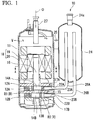
- FIG. 1 is a side cross-sectional view of a rotary compressor according to a first embodiment of the present invention.
- a compressor 10 includes a motor 18, a crankshaft 16 rotating along with the motor 18, piston rotors 13A and 13B eccentrically rotating along with the rotation of the crankshaft 16, cylinders 12A and 12B having compression chambers for accommodating the piston rotors 13A and 13B formed therein, and a housing 11 forming a discharge space V through which a compressed refrigerant is discharged and surrounding the cylinders 12A and 12B.
- the compressor 10 is a so-called two-cylinder type rotary compressor in which the disk-shaped cylinders 12A and 12B are provided in two upper and lower stages in the cylindrical housing 11.
- the cylindrical piston rotors 13A and 13B having external forms smaller than inner sides of inner wall surfaces of the cylinders are arranged in the cylinders 12A and 12B.
- the piston rotors 13A and 13B are inserted and fixed into eccentric shaft parts 14A and 14B of a rotational axis along a central axis of the housing 11.
- the upper-cylinder-side piston rotors 13A and the lower-cylinder-side piston rotor 13B are provided such that their phases differ from each other by 180°.
- a disk-shaped partition plate 15 is provided between the upper and lower cylinders 12A and 12B.
- a space R in the upper-side cylinder 12A and a lower space R are partitioned into compression chambers R1 and R2 by the partition plate 15 without communicating with each other.
- the crankshaft 16 is supported to be rotatable about an axis O by an upper bearing part 17A fixed to the cylinder 12A and a lower bearing part 17B fixed to the cylinder 12B.
- the crankshaft 16 has the eccentric shaft parts 14A and 14B offset in a direction perpendicular to a central line of the crankshaft 16.
- the eccentric shaft parts 14A and 14B are pivoted about a central axis of the crankshaft 16 so that the upper and lower piston rotors 13A and 13B rotate eccentrically in the cylinder 12A and 12B following such pivoting.
- crankshaft 16 protrudes upward (that is, in a direction in which the motor 18 is located when viewed from the compressor 10) from the upper bearing part 17A.
- a motor rotor 19 of the motor 18 configured to rotatably drive the crankshaft 16 is integrally provided on one end portion of the crankshaft 16 in an axis O direction.
- a stator 20 is fixed and provided on an inner circumferential surface of the housing 11 to face an outer circumferential portion of the motor rotor 19.
- an accumulator 24 configured to perform gas-liquid separation on a refrigerant before supplying the refrigerant to the compressor 10 is fixed to the housing 11 via a stay 25.
- Intake pipes 26A and 26B configured to suction a refrigerant in the accumulator 24 into the compressor 10 are provided in the accumulator 24. Distal end portions of the intake pipes 26A and 26B are connected to suction ports 23A and 23B through openings 22A and 22B.
- the compressor 10 takes the refrigerant from a suction port 24a of the accumulator 24 into the accumulator 24.
- the compressor 10 performs gas-liquid separation on the refrigerant in the accumulator 24, and supplies the gas phase from the intake pipes 26A and 26B to the compression chambers R1 and R2 serving as internal spaces of the cylinder 12A and 12B via the suction ports 23A and 23B of the cylinder 12A and 12B.
- the piston rotors 13A and 13B eccentrically rotate so that the volumes of the compression chambers R1 and R2 gradually decrease and thus the refrigerant is compressed.
- the refrigerant passes around the motor 18 and is then discharged to a pipe 27 constituting a refrigeration cycle via a discharge port provided at an upper part.
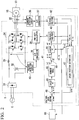
- FIG. 2 is a first diagram showing a control circuit of the rotary compressor according to the embodiment of the present invention.
- FIG. 2 illustrates a block diagram of a sensorless vector control circuit 1 configured to control the motor 18.
- the sensorless vector control circuit 1 shown in FIG. 2 includes a converter 31, a capacitor 32, a reactor 33, an inverter 34, a current sensor 35, a current detection circuit 36, an analog/digital (A/D) conversion circuit 37, a pulse width modulation (PWM) duty calculation circuit 38, an A/D conversion circuit 39, a voltage detection circuit 40, and a full vector control circuit 41.
- A/D analog/digital
- PWM pulse width modulation
- the full vector control circuit 41 includes a two-phase/three-phase conversion circuit 42, a two-phase/three-phase conversion circuit 43, a current PI control circuit 44, a current conversion table 45, a speed PI control circuit 46, a speed position estimation circuit 47, a subtractor 48, and a subtractor 49.
- a rotary compressor system includes a rotational speed control device 60, the sensorless vector control circuit 1, and a rotary compressor 10.
- the converter 31 rectifies a three-phase alternating current (AC) input from a power system E.
- the capacitor 32 and the reactor 33 smooth the rectified voltage and generate a direct current (DC) voltage.
- the inverter 34 generates a three-phase drive voltage from the DC input voltage on the basis of a duty command value output by the PWM duty calculation circuit 38 and supplies a drive voltage to the motor 18 included in the compressor 10.
- the sensorless vector control circuit 1 drives the motor 18.
- the current detection circuit 36 detects a current flowing through the motor 18 and outputs the detected current to the A/D conversion circuit 37.
- the A/D conversion circuit 37 converts the current detected by the current detection circuit 36 into a digital signal and outputs the converted signal to the full vector control circuit 41.
- the two-phase/three-phase conversion circuit 42 performs coordinate conversion (dq conversion) on a three-phase signal input from the A/D conversion circuit 37 and outputs the converted current values id and iq to the speed position estimation circuit 47.
- the two-phase/three-phase conversion circuit 42 refers to a previous estimation value ⁇ es of a magnetic pole angle by the motor rotor 19, which will be described below.
- the speed position estimation circuit 47 receives current values id and iq and electric power command values vd and vq in a dq coordinate system output by the current PI control circuit 44 as inputs and calculates an estimation value ⁇ es of a rotational speed of the motor 18 and an estimation value ⁇ es of a magnetic pole angle (an angle of a magnetic pole position) of the motor rotor 19 using, for example, a method called a model reference adaptive system (MRAS).
- MRAS model reference adaptive system
- the rotational speed control device 60 outputs a command value ⁇ cmd of a rotational speed to a full vector control circuit 41.
- the subtracter 48 calculates a deviation ⁇ between a command value ⁇ cmd of a rotational speed by a rotational speed control device 60 and an estimation value ⁇ es of a rotational speed estimated by the speed position estimation circuit 47 and outputs the calculated deviation to the speed PI control circuit 46.
- the speed PI control circuit 46 calculates a torque command value for reducing the deviation (to 0) by PI control on the basis of ⁇ .
- the full vector control circuit 41 converts the torque command value into current command values id' and iq' on the basis of the current conversion table 45.
- the subtractor 49 calculates deviations ⁇ id and ⁇ iq between the current command values id' and iq' and id and iq output by the two-phase/three-phase conversion circuit 42 and outputs the calculated deviations to the current PI control circuit 44.
- the current PI control circuit 44 calculates voltage command values vd and vq for reducing the deviations by the PI control on the basis of the deviations ⁇ id and ⁇ iq.
- the current PI control circuit 44 outputs the voltage command values vd and vq to the two-phase/three-phase conversion circuit 43.
- the two-phase/three-phase conversion circuit 43 performs coordinate conversion of the voltage command values vd and vq from two phases to three phases by referring to the estimation value ⁇ es of the magnetic pole angle of the motor rotor 19 estimated by the speed position estimation circuit 47 and outputs the converted voltage command value V to the PWM duty calculation circuit 38.
- the PWM duty calculation circuit 38 receives the voltage command value V and a signal obtained by digitally converting the DC input voltage to the inverter 34 detected by the voltage detection circuit 40 using the A/D conversion circuit 39 as inputs and calculates a duty command value.
- the PWM duty calculation circuit 38 outputs the calculated duty command value to the inverter 34.
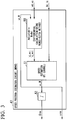
- FIG. 3 is a second diagram showing the control circuit of the rotary compressor according to the embodiment of the present invention.
- FIG. 3 illustrates a block diagram of the speed position estimation circuit 47.
- the speed position estimation circuit 47 includes a current-estimating circuit 50, a speed-estimating circuit 51, and an integrating circuit 52.
- the current-estimating circuit 50 receives the electric power command values vd and vq and an estimation value ⁇ _M of the rotational speed of the motor rotor 19 estimated by the speed-estimating circuit 51 as inputs and estimates current estimation values id_est and iq_est on the basis of an adaptive model (an adjustable model) obtained by modeling the motor 18.
- the speed-estimating circuit 51 receives the current estimation values id_est and iq_est and id and iq as inputs and estimates a rotational speed ( ⁇ _M).
- the integrating circuit 52 integrates the estimation value ⁇ _M of the rotational speed and calculates an estimation value ⁇ es of the magnetic pole angle of the motor rotor 19.
- the speed position estimation circuit 47 uses the estimation value ⁇ _M of the rotational speed estimated by the speed-estimating circuit 51 as the estimation value ⁇ es of the rotational speed and outputs the estimation value ⁇ _M together with the estimation value ⁇ es of the magnetic pole angle of the motor rotor 19 calculated by the integrating circuit 52.
- the inside of the compressor 10 becomes a high-temperature and high-pressure environment, it is difficult to provide a sensor configured to detect a position of the piston rotor 13.
- sensorless vector control for example, MRAS control
- the rotational speed or the magnetic pole angle of the motor rotor 19 can be detected with high accuracy without using a sensor.
- the motor rotor 19, the crankshaft 16, and the piston rotors 13A and 13B are integrally constituted and rotate, it is thought that a magnetic pole angle of the motor rotor 19 and positions of the piston rotors 13A and 13B are in a certain positional relationship.
- the positions of the piston rotors 13A and 13B are estimated and controlled with high accuracy using the MRAS control so that a variation in an angular velocity of the crankshaft 16 can be minimized.
- the rotary compressor receives a force from a high-pressure refrigerant gas as the compression of the refrigerant gas in the cylinders 12A and 12B progresses, the gas compression torque largely fluctuates during one compression process. With that influence, a variation occurs in the angular velocity of the crankshaft 16 during the compression process.
- the rotational speed control device 60 calculates a command value of the rotational speed to minimize variations appearing in estimation values for a rotational speed or a magnetic pole angle of the motor rotor 19 so that the angular velocity variation of the crankshaft 16 can be minimized.
- FIG. 4 is a cross-sectional view of a motor included in the rotary compressor according to the embodiment of the present invention.
- FIG. 4 illustrates a motor 18 in a cross-sectional view taken along line A-A in the compressor 10 of FIG. 1 .
- FIG. 4 is the cross-sectional view of the motor 18 to which the MRAS control according to the embodiment is actually applied and which can drive the compressor 10 at a desired rotational speed by minimizing fluctuations in the rotational speed.
- the stator 20 includes six tooth parts 3, six winding slot parts 4, and a yoke part 5.
- a tooth width 3d is 8 mm and a stator outer diameter 20d is 105 mm.
- Magnets 6 corresponding to four poles are arranged in the motor rotor 19.
- An outer diameter 19d of the motor rotor 19 is 46.8 mm.
- FIG. 5 is a cross-sectional view of a conventional motor included in a rotary compressor illustrated for comparison.
- FIG. 5 is the cross-sectional view of the motor incorporated in the compressor 10 and used instead of the motor 18 when the MRAS control is not applied.
- a stator 20' includes six tooth parts 3', six winding slot parts 4', and a yoke part 5'.
- a tooth width 3d' is 10 mm and a stator outer diameter 20d' is 105 mm.
- Magnets 6' corresponding to four poles are arranged in a motor rotor 19'.
- An outer diameter 19d' of the motor rotor 19' is 54.8 mm.
- the outer diameter of the motor rotor 19 can be reduced (for example, from 54.8 mm to 46.8 mm) as described above.
- areas of the winding slot parts 4 of the stator 20 can be increased as illustrated in the drawing by reducing the outer diameter of the motor rotor 19.
- the total area of the winding slot parts 4 is about 1.7 times the total area of the winding slot parts 4'.
- a ratio of the total area of the six winding slot parts 4 to an area of the entire stator 20 is about 32%.
- a ratio of the total area of the six winding slot parts 4' to an area of the entire stator 20' is about 23%. Note that, for calculation purposes, it is thought that the winding slot area can be enlarged to the same extent even for a motor with the same size (for example, a motor with a stator outer diameter in a range of 100 mm to 112) used for a rotary compressor of an air conditioner. Furthermore, even when the ratio of the total area of the six winding slot parts 4 to the area of the entire stator 20 is not 32%, design can also be performed so that the ratio thereof takes any value between 25% and 40%.
- 25% is computationally a lower limit value of the above ratio when a significant effect of a copper loss-reducing effect described below can be obtained as compared to the related art (in the case of 23%). Since problems such as strength, vibrations, and noise occur when the ratio of the total area of the winding slot parts 4 to the area of the entire stator 20 is too large, 40% is the maximum value of the above ratio in which an operation can be performed while avoiding such problems. Even with regard to the motor designed with the above ratio in a range of 25% to 40%, it is thought that a motor efficiency improvement effect described below can be obtained as compared to the conventional motor mounted in the rotary compressor designed for the air conditioner.
- stator outer diameter is 105 mm.
- a size of a motor rotor of a motor mounted in a rotary compressor for an air conditioner a stator outer diameter of which is in a range of 100 mm to 112 mm, is reduced to the same extent.
- a size of a motor having a stator outer diameter of 125 mm is also reduced assuming MRAS control. In the case of such a motor, before the MRAS control is applied, the outer diameter of the motor rotor is 54.8 mm when the stator outer diameter is 125 mm.
- the outer diameter of the motor rotor of a motor having a stator outer diameter in the range of 100 mm to 112 mm can also be designed to be, for example, less than 50 mm while applying the MRAS control. Even in that case, it is thought that high efficiency can be obtained as compared to the conventional motor mounted in the rotary compressor designed for the air conditioner.
- 46.8 mm is a lower limit value of the calculation of the outer diameter of the motor rotor from which a motor efficiency improvement effect can be obtained.
- the efficiency of the motor can be improved by designing an outer diameter of a motor rotor 19 of a motor, in which a stator outer diameter is 100 mm or more and 125 mm or less, to be 46.8 mm or more and less than 50 mm.
- a stator outer diameter is 100 mm or more and 125 mm or less
- the fluctuation of the rotational speed can be minimized using the MRAS control, it is possible to reduce the size and weight of the motor rotor 19 and improve the efficiency of the motor 18 as described above. Furthermore, it is possible to reduce an amount of use of the magnet 6 and reduce manufacturing costs by reducing the outer diameter of the motor rotor 19.
- the areas of the winding slot parts 4 can be increased by increasing the area of the stator 20 to a space occupied by the motor rotor 19.
- a winding diameter of a coil can be increased by increasing the areas of the winding slot parts 4. It is possible to reduce a resistance value and reduce the copper loss by increasing the winding diameter of the coil.
- APF annual performance factor
- motors such as a permanent magnet synchronous motor and an induction motor can be applied as the motor 18.
- stator outer diameter is 100 mm to 112 mm and an example in which the stator outer diameter is 125 mm have been described in the above-described embodiment
- the present invention is not limited thereto.
- a size of a motor having a stator outer diameter including 125 mm in the above example is about 125 mm to 135 mm; likewise, a motor having a stator outer diameter of about 90 mm, or a motor having a stator outer diameter of about 170 mm can be reduced to the same extent.
- rotor outer diameters of a motor having a stator outer diameter of about 125 mm to 135 mm, a motor having a stator outer diameter of about 90 mm, and a motor having a stator outer diameter of about 170 mm can also be set to about 46.8 mm.
- the constituent elements in the above-described embodiment can be appropriately replaced with well-known constituent elements without departing from the scope of the present invention, which is defined by the claims.
- the technical scope of the present invention is not limited to the above-described embodiment and various modifications can be performed without departing from the scope of the present invention as defined by the claims.
- the rotary compressor system includes the rotational speed control device 60, the sensorless vector control circuit 1, and the rotary compressor 10.
- the rotary compressor system according to the embodiment is used for an air conditioner.
- the total area of the six winding slot parts 4 is an example of the winding slot area and the entire area of the stator 20 is an example of the stator area.
Landscapes
- Engineering & Computer Science (AREA)
- Power Engineering (AREA)
- Applications Or Details Of Rotary Compressors (AREA)
- Connection Of Motors, Electrical Generators, Mechanical Devices, And The Like (AREA)
- Permanent Magnet Type Synchronous Machine (AREA)
- Control Of Ac Motors In General (AREA)
Abstract
Description
- The present invention relates to a rotary compressor system, a rotary compressor, and a motor.
- Priority is claimed on Japanese Patent Application No.
2016-230973, filed November 29, 2016 - In response to a demand for energy saving in recent years, an annual performance factor (APF) has also been emphasized in a compressor for an air conditioner. Generally, the efficiencies of compressors are lowered in a low-speed operation in many cases and efficiency improvement in a low-speed region also greatly contributes to the improvement of an APF. In losses of motors included in compressors, copper loss is dominant in a low-speed operation and the copper loss needs to be reduced to improve the efficiency in a low-speed region.
- Examples of a method of reducing copper loss include a method of increasing a winding diameter and lowering a winding resistance value by reducing an outer diameter of a motor rotor to increase a stator winding slot.
- Note that Patent Document 1 discloses an air conditioner designed so that a ratio of an amount of heat given by the radiator to an amount of refrigerant discharge per revolution of the compressor of a radiator and a compressor included in an air conditioner falls within a predetermined range to improve the energy efficiency in an air conditioner. Furthermore, Patent Document 1 discloses a ratio of a motor length to a stator outer diameter or a ratio of a motor length to a rotor outer diameter of a motor included in the compressor.
- [Patent Document 1] Japanese Unexamined Patent Application, First Publication No.
2008-215747 - However, when an outer diameter of a motor rotor decreases, inertia in a rotational direction decreases, a variation in angular velocity occurs due to a variation in gas compression torque and thus the efficiency of a motor decreases. Therefore, this does not lead to the improvement of an APF. In order to improve the efficiency of the motor, it has been required to reduce the outer diameter of the motor rotor.
- Therefore, an objective of the present invention is to provide a rotary compressor system, a rotary compressor, and a motor capable of solving the above-described problems.
- A first aspect of the present invention is a rotary compressor system, including: a rotary compressor; and a sensorless vector control circuit configured to control a motor included in the rotary compressor, wherein an outer diameter of a motor rotor of the motor is 46.8 mm or more and less than 50 mm.
- In the rotary compressor system according to a second aspect of the present invention, an outer diameter of a motor rotor of the motor may be 46.8 mm or more and 49 mm or less.
- In the rotary compressor system according to a third aspect of the present invention, an outer diameter of a motor rotor of the motor may be 46.8 mm.
- A fourth aspect of the present invention is a rotary compressor, including: a motor controlled by sensorless vector control, wherein an outer diameter of a motor rotor of the motor is 46.8 mm or more and less than 50 mm.
- A fifth aspect of the present invention is a rotary compressor for an air conditioner, the rotary compressor including a motor having an outer diameter of a motor rotor of 46.8 mm or more and less than 50 mm.
- A sixth aspect of the present invention is a motor for mounting in a rotary compressor for an air conditioner, wherein an outer diameter of a motor rotor of the motor is 46.8 mm or more and less than 50 mm.
- According to the present invention, it is possible to reduce the copper loss of a motor, realize high efficiency of the motor, and realize high efficiency of a compressor.
-
-
FIG. 1 is a vertical cross-sectional view of a rotary compressor according to an embodiment of the present invention. -
FIG. 2 is a first diagram showing a control circuit of the rotary compressor according to the embodiment of the present invention. -
FIG. 3 is a second diagram showing a control circuit of the rotary compressor according to the embodiment of the present invention. -
FIG. 4 is a cross-sectional view of a motor included in the rotary compressor according to the embodiment of the present invention. -
FIG. 5 is a cross-sectional view of a conventional motor included in a rotary compressor. - A rotary compressor system according to embodiments of the present invention will be described below with reference to
FIGS. 1 to 5 . -
FIG. 1 is a side cross-sectional view of a rotary compressor according to a first embodiment of the present invention. - As shown in
FIG. 1 , acompressor 10 according to the embodiment includes amotor 18, acrankshaft 16 rotating along with themotor 18,piston rotors crankshaft 16,cylinders 12A and 12B having compression chambers for accommodating thepiston rotors housing 11 forming a discharge space V through which a compressed refrigerant is discharged and surrounding thecylinders 12A and 12B. - The
compressor 10 is a so-called two-cylinder type rotary compressor in which the disk-shaped cylinders 12A and 12B are provided in two upper and lower stages in thecylindrical housing 11. Thecylindrical piston rotors cylinders 12A and 12B. Thepiston rotors eccentric shaft parts housing 11. - The upper-cylinder-
side piston rotors 13A and the lower-cylinder-side piston rotor 13B are provided such that their phases differ from each other by 180°. - A disk-
shaped partition plate 15 is provided between the upper andlower cylinders 12A and 12B. A space R in the upper-side cylinder 12A and a lower space R are partitioned into compression chambers R1 and R2 by thepartition plate 15 without communicating with each other. - The
crankshaft 16 is supported to be rotatable about an axis O by an upper bearingpart 17A fixed to thecylinder 12A and alower bearing part 17B fixed to the cylinder 12B. - The
crankshaft 16 has theeccentric shaft parts crankshaft 16. Theeccentric shaft parts crankshaft 16 so that the upper andlower piston rotors cylinder 12A and 12B following such pivoting. - The
crankshaft 16 protrudes upward (that is, in a direction in which themotor 18 is located when viewed from the compressor 10) from the upper bearingpart 17A. Amotor rotor 19 of themotor 18 configured to rotatably drive thecrankshaft 16 is integrally provided on one end portion of thecrankshaft 16 in an axis O direction. Astator 20 is fixed and provided on an inner circumferential surface of thehousing 11 to face an outer circumferential portion of themotor rotor 19. - In the
compressor 10, anaccumulator 24 configured to perform gas-liquid separation on a refrigerant before supplying the refrigerant to thecompressor 10 is fixed to thehousing 11 via astay 25.Intake pipes accumulator 24 into thecompressor 10 are provided in theaccumulator 24. Distal end portions of theintake pipes suction ports openings - The
compressor 10 takes the refrigerant from asuction port 24a of theaccumulator 24 into theaccumulator 24. To be specific, thecompressor 10 performs gas-liquid separation on the refrigerant in theaccumulator 24, and supplies the gas phase from theintake pipes cylinder 12A and 12B via thesuction ports cylinder 12A and 12B. - Moreover, the
piston rotors motor 18 and is then discharged to apipe 27 constituting a refrigeration cycle via a discharge port provided at an upper part. -
FIG. 2 is a first diagram showing a control circuit of the rotary compressor according to the embodiment of the present invention. -
FIG. 2 illustrates a block diagram of a sensorless vector control circuit 1 configured to control themotor 18. The sensorless vector control circuit 1 shown inFIG. 2 includes aconverter 31, acapacitor 32, areactor 33, aninverter 34, acurrent sensor 35, acurrent detection circuit 36, an analog/digital (A/D)conversion circuit 37, a pulse width modulation (PWM)duty calculation circuit 38, an A/D conversion circuit 39, avoltage detection circuit 40, and a fullvector control circuit 41. Furthermore, the fullvector control circuit 41 includes a two-phase/three-phase conversion circuit 42, a two-phase/three-phase conversion circuit 43, a currentPI control circuit 44, a current conversion table 45, a speedPI control circuit 46, a speedposition estimation circuit 47, asubtractor 48, and asubtractor 49. - Note that a rotary compressor system includes a rotational
speed control device 60, the sensorless vector control circuit 1, and arotary compressor 10. - The
converter 31 rectifies a three-phase alternating current (AC) input from a power system E. Thecapacitor 32 and thereactor 33 smooth the rectified voltage and generate a direct current (DC) voltage. Theinverter 34 generates a three-phase drive voltage from the DC input voltage on the basis of a duty command value output by the PWMduty calculation circuit 38 and supplies a drive voltage to themotor 18 included in thecompressor 10. Thus, the sensorless vector control circuit 1 drives themotor 18. - The
current detection circuit 36 detects a current flowing through themotor 18 and outputs the detected current to the A/D conversion circuit 37. The A/D conversion circuit 37 converts the current detected by thecurrent detection circuit 36 into a digital signal and outputs the converted signal to the fullvector control circuit 41. In the fullvector control circuit 41, the two-phase/three-phase conversion circuit 42 performs coordinate conversion (dq conversion) on a three-phase signal input from the A/D conversion circuit 37 and outputs the converted current values id and iq to the speedposition estimation circuit 47. At this time, the two-phase/three-phase conversion circuit 42 refers to a previous estimation value θes of a magnetic pole angle by themotor rotor 19, which will be described below. The speedposition estimation circuit 47 receives current values id and iq and electric power command values vd and vq in a dq coordinate system output by the currentPI control circuit 44 as inputs and calculates an estimation value ωes of a rotational speed of themotor 18 and an estimation value θes of a magnetic pole angle (an angle of a magnetic pole position) of themotor rotor 19 using, for example, a method called a model reference adaptive system (MRAS). - The rotational
speed control device 60 outputs a command value ωcmd of a rotational speed to a fullvector control circuit 41. Thesubtracter 48 calculates a deviation Δω between a command value ωcmd of a rotational speed by a rotationalspeed control device 60 and an estimation value ωes of a rotational speed estimated by the speedposition estimation circuit 47 and outputs the calculated deviation to the speedPI control circuit 46. The speedPI control circuit 46 calculates a torque command value for reducing the deviation (to 0) by PI control on the basis of Δω. The fullvector control circuit 41 converts the torque command value into current command values id' and iq' on the basis of the current conversion table 45. Thesubtractor 49 calculates deviations Δid and Δiq between the current command values id' and iq' and id and iq output by the two-phase/three-phase conversion circuit 42 and outputs the calculated deviations to the currentPI control circuit 44. The currentPI control circuit 44 calculates voltage command values vd and vq for reducing the deviations by the PI control on the basis of the deviations Δid and Δiq. The currentPI control circuit 44 outputs the voltage command values vd and vq to the two-phase/three-phase conversion circuit 43. The two-phase/three-phase conversion circuit 43 performs coordinate conversion of the voltage command values vd and vq from two phases to three phases by referring to the estimation value θes of the magnetic pole angle of themotor rotor 19 estimated by the speedposition estimation circuit 47 and outputs the converted voltage command value V to the PWMduty calculation circuit 38. The PWMduty calculation circuit 38 receives the voltage command value V and a signal obtained by digitally converting the DC input voltage to theinverter 34 detected by thevoltage detection circuit 40 using the A/D conversion circuit 39 as inputs and calculates a duty command value. The PWMduty calculation circuit 38 outputs the calculated duty command value to theinverter 34. -
FIG. 3 is a second diagram showing the control circuit of the rotary compressor according to the embodiment of the present invention. -
FIG. 3 illustrates a block diagram of the speedposition estimation circuit 47. The speedposition estimation circuit 47 includes a current-estimatingcircuit 50, a speed-estimatingcircuit 51, and an integratingcircuit 52. The current-estimatingcircuit 50 receives the electric power command values vd and vq and an estimation value ω_M of the rotational speed of themotor rotor 19 estimated by the speed-estimatingcircuit 51 as inputs and estimates current estimation values id_est and iq_est on the basis of an adaptive model (an adjustable model) obtained by modeling themotor 18. The speed-estimatingcircuit 51 receives the current estimation values id_est and iq_est and id and iq as inputs and estimates a rotational speed (ω_M). The integratingcircuit 52 integrates the estimation value ω_M of the rotational speed and calculates an estimation value θes of the magnetic pole angle of themotor rotor 19. The speedposition estimation circuit 47 uses the estimation value ω_M of the rotational speed estimated by the speed-estimatingcircuit 51 as the estimation value ωes of the rotational speed and outputs the estimation value ω_M together with the estimation value θes of the magnetic pole angle of themotor rotor 19 calculated by the integratingcircuit 52. - Since the inside of the
compressor 10 becomes a high-temperature and high-pressure environment, it is difficult to provide a sensor configured to detect a position of the piston rotor 13. According to sensorless vector control (for example, MRAS control) using the control circuit shown inFIGS. 2 and3 , the rotational speed or the magnetic pole angle of themotor rotor 19 can be detected with high accuracy without using a sensor. Furthermore, since themotor rotor 19, thecrankshaft 16, and thepiston rotors motor rotor 19 and positions of thepiston rotors piston rotors crankshaft 16 can be minimized. Generally, since the rotary compressor receives a force from a high-pressure refrigerant gas as the compression of the refrigerant gas in thecylinders 12A and 12B progresses, the gas compression torque largely fluctuates during one compression process. With that influence, a variation occurs in the angular velocity of thecrankshaft 16 during the compression process. However, when the MRAS control according to the embodiment is introduced, the rotationalspeed control device 60 calculates a command value of the rotational speed to minimize variations appearing in estimation values for a rotational speed or a magnetic pole angle of themotor rotor 19 so that the angular velocity variation of thecrankshaft 16 can be minimized. - When countermeasures against a gas compression torque fluctuation during the compression process are considered from another point of view, in the motor control in the related art (when the MRAS control is not used), it is necessary to gain inertia by designing a size of the
motor rotor 19 to a certain extent to reduce the influence of the gas compression torque fluctuation. However, since the rotational speed of themotor rotor 19 can be kept constant by introducing the MRAS control, themotor rotor 19 can be miniaturized without considering the above restriction. The efficiency of the motor can be improved by reducing a size of themotor rotor 19. Next, an example of miniaturization of themotor rotor 19 and its effects will be described. -
FIG. 4 is a cross-sectional view of a motor included in the rotary compressor according to the embodiment of the present invention.FIG. 4 illustrates amotor 18 in a cross-sectional view taken along line A-A in thecompressor 10 ofFIG. 1 .FIG. 4 is the cross-sectional view of themotor 18 to which the MRAS control according to the embodiment is actually applied and which can drive thecompressor 10 at a desired rotational speed by minimizing fluctuations in the rotational speed. - In
FIG. 4 , thestator 20 includes sixtooth parts 3, six windingslot parts 4, and ayoke part 5. In thestator 20, atooth width 3d is 8 mm and a statorouter diameter 20d is 105 mm.Magnets 6 corresponding to four poles are arranged in themotor rotor 19. Anouter diameter 19d of themotor rotor 19 is 46.8 mm. -
FIG. 5 is a cross-sectional view of a conventional motor included in a rotary compressor illustrated for comparison.FIG. 5 is the cross-sectional view of the motor incorporated in thecompressor 10 and used instead of themotor 18 when the MRAS control is not applied. - In
FIG. 5 , a stator 20' includes six tooth parts 3', six winding slot parts 4', and a yoke part 5'. In the stator 20', atooth width 3d' is 10 mm and a statorouter diameter 20d' is 105 mm. Magnets 6' corresponding to four poles are arranged in a motor rotor 19'. Anouter diameter 19d' of the motor rotor 19' is 54.8 mm. - When a speed fluctuation suppression effect using the MRAS control is assumed, the outer diameter of the
motor rotor 19 can be reduced (for example, from 54.8 mm to 46.8 mm) as described above. Furthermore, areas of the windingslot parts 4 of thestator 20 can be increased as illustrated in the drawing by reducing the outer diameter of themotor rotor 19. For example, in the illustrated example, the total area of the windingslot parts 4 is about 1.7 times the total area of the winding slot parts 4'. Furthermore, in the case of thestator 20 illustrated inFIG. 4 , a ratio of the total area of the six windingslot parts 4 to an area of theentire stator 20 is about 32%. On the other hand, in the case of the stator 20' in the related art illustrated inFIG. 5 , a ratio of the total area of the six winding slot parts 4' to an area of the entire stator 20' is about 23%. Note that, for calculation purposes, it is thought that the winding slot area can be enlarged to the same extent even for a motor with the same size (for example, a motor with a stator outer diameter in a range of 100 mm to 112) used for a rotary compressor of an air conditioner. Furthermore, even when the ratio of the total area of the six windingslot parts 4 to the area of theentire stator 20 is not 32%, design can also be performed so that the ratio thereof takes any value between 25% and 40%. 25% is computationally a lower limit value of the above ratio when a significant effect of a copper loss-reducing effect described below can be obtained as compared to the related art (in the case of 23%). Since problems such as strength, vibrations, and noise occur when the ratio of the total area of the windingslot parts 4 to the area of theentire stator 20 is too large, 40% is the maximum value of the above ratio in which an operation can be performed while avoiding such problems. Even with regard to the motor designed with the above ratio in a range of 25% to 40%, it is thought that a motor efficiency improvement effect described below can be obtained as compared to the conventional motor mounted in the rotary compressor designed for the air conditioner. - A ratio of the outer diameter of the motor rotor to the stator outer diameter is 46.8 mm/105 mm = 0.4457 ··· in the case of the
motor rotor 19 and thestator 20 illustrated inFIG. 4 . On the other hand, the ratio thereof is 55 mm/105 mm = 0.5238 ··· in the case of the motor rotor 19' and the stator 20' illustrated inFIG. 5 . Note that, although themotor 18 in which the stator outer diameter is 105 mm has been exemplified in the above example, it is thought that a size of a motor rotor of a motor mounted in a rotary compressor for an air conditioner, a stator outer diameter of which is in a range of 100 mm to 112 mm, is reduced to the same extent. In addition, a size of a motor having a stator outer diameter of 125 mm is also reduced assuming MRAS control. In the case of such a motor, before the MRAS control is applied, the outer diameter of the motor rotor is 54.8 mm when the stator outer diameter is 125 mm. With regard to the motor before the MRAS control is applied, a ratio of the outer diameter of the motor rotor to the stator outer diameter is 54.8 mm/125 mm = 0.4384. Furthermore, an outer diameter of the miniaturized motor rotor after applying the MRAS control is 46.8 mm. A ratio of the outer diameter of the motor rotor to the stator outer diameter in the miniaturized motor rotor is 46.8 mm/125 mm = 0.3744. - Note that, since the outer diameter of the motor rotor of a motor having a stator outer diameter of 125 mm has also been reduced to 46.8 mm, it is thought that an outer diameter of a motor rotor of a motor having a stator outer diameter in a range of 100 mm to 125 mm including a motor having a stator outer diameter in a range of 100 mm to 112 mm can be reduced to 46.8 mm.
- Note that, even when the outer diameter of the
motor rotor 19 is not reduced to 46.8 mm, the outer diameter of the motor rotor of a motor having a stator outer diameter in the range of 100 mm to 112 mm can also be designed to be, for example, less than 50 mm while applying the MRAS control. Even in that case, it is thought that high efficiency can be obtained as compared to the conventional motor mounted in the rotary compressor designed for the air conditioner. Note that 46.8 mm is a lower limit value of the calculation of the outer diameter of the motor rotor from which a motor efficiency improvement effect can be obtained. - In other words, the efficiency of the motor can be improved by designing an outer diameter of a
motor rotor 19 of a motor, in which a stator outer diameter is 100 mm or more and 125 mm or less, to be 46.8 mm or more and less than 50 mm. In addition, in order to obtain more remarkable effects, it is desirable to design the outer diameter of themotor rotor 19 to be 46.8 mm or more and 49 mm or less. - A ratio of a motor rotor weight to a stator weight is 0.80 kg/3.20 kg = 0.25 in the case of the
motor rotor 19 and thestator 20 illustrated inFIG. 4 . On the other hand, the ratio thereof is 1.14 kg/3.07 kg = 0.3713··· in the case of the motor rotor 19' and the stator 20' illustrated inFIG. 5 . Note that, since a motor having a stator outer diameter of 125 mm is miniaturized after applying the MRAS control, a ratio of the motor rotor weight to the stator weight is 1.23 kg/4.66 kg = 0.2639 ···. - According to the embodiment, since the fluctuation of the rotational speed can be minimized using the MRAS control, it is possible to reduce the size and weight of the
motor rotor 19 and improve the efficiency of themotor 18 as described above. Furthermore, it is possible to reduce an amount of use of themagnet 6 and reduce manufacturing costs by reducing the outer diameter of themotor rotor 19. The areas of the windingslot parts 4 can be increased by increasing the area of thestator 20 to a space occupied by themotor rotor 19. A winding diameter of a coil can be increased by increasing the areas of the windingslot parts 4. It is possible to reduce a resistance value and reduce the copper loss by increasing the winding diameter of the coil. Thus, it is possible to improve the efficiency of themotor 18, achieve high efficiency of thecompressor 10, and improve an annual performance factor (APF). - For example, in the case of a heating intermediate output operation in which a contribution rate for improving the APF is higher (which is an operation state in which the APF is lower) than that of an operation with a heating rated output, a cooling rated output, and a cooling intermediate output, it is known that a percentage of copper loss is higher than that of iron loss in motor loss. Therefore, it is possible to reduce the copper loss of the
motor 18 in the heating intermediate output operation and improve the efficiency of the motor, the compressor efficiency, and the APF of the air conditioner by applying the rotary compressor system according to the embodiment to the air conditioner. - Note that various motors such as a permanent magnet synchronous motor and an induction motor can be applied as the
motor 18. - Although an example in which the stator outer diameter is 100 mm to 112 mm and an example in which the stator outer diameter is 125 mm have been described in the above-described embodiment, the present invention is not limited thereto. For example, a size of a motor having a stator outer diameter including 125 mm in the above example is about 125 mm to 135 mm; likewise, a motor having a stator outer diameter of about 90 mm, or a motor having a stator outer diameter of about 170 mm can be reduced to the same extent. For example, it is thought that rotor outer diameters of a motor having a stator outer diameter of about 125 mm to 135 mm, a motor having a stator outer diameter of about 90 mm, and a motor having a stator outer diameter of about 170 mm can also be set to about 46.8 mm.
- In addition, the constituent elements in the above-described embodiment can be appropriately replaced with well-known constituent elements without departing from the scope of the present invention, which is defined by the claims. Furthermore, the technical scope of the present invention is not limited to the above-described embodiment and various modifications can be performed without departing from the scope of the present invention as defined by the claims. For example, although a four-pole and six-slot motor has been exemplified in the above example, it is thought that similar results can be obtained with motors having other poles and other slots (for example, six poles and nine slots). Note that the rotary compressor system includes the rotational
speed control device 60, the sensorless vector control circuit 1, and therotary compressor 10. The rotary compressor system according to the embodiment is used for an air conditioner. - Note that the total area of the six winding
slot parts 4 is an example of the winding slot area and the entire area of thestator 20 is an example of the stator area. - While preferred embodiments of the invention have been described and illustrated above, it should be understood that these are exemplary of the invention and are not to be considered as limiting. Additions, omissions, substitutions, and other modifications can be made without departing from the scope of the present invention, which is defined by the claims. Accordingly, the invention is not to be considered as being limited by the foregoing description, and is only limited by the scope of the appended claims.
-
- 1 Sensorless vector control circuit
- 3,3' Tooth part
- 3d, 3d' Tooth width
- 4, 4' Winding slot part
- 5, 5' Yoke part
- 6, 6' Magnet
- 10 Compressor
- 11 Housing
- 12A, 12B Cylinder
- 13A, 13B Piston rotor
- 16 Crankshaft
- 18 Motor
- 19, 19' Motor rotor
- 20, 20' Stator
- 20d, 20d' Stator outer diameter
- 22A, 22B Opening
- 23A, 23B Suction port
- 24 Accumulator
- 25 Stay
- 26A, 26B Intake pipe
- 31 Converter
- 32 Capacitor
- 33 Reactor
- 34 Inverter
- 35 Current sensor
- 36 Current detection circuit
- 37 A/D conversion circuit
- 38 PWM duty calculation circuit
- 39 A/D conversion circuit
- 40 Voltage detection circuit
- 41 Full vector control circuit
- 42, 43 Two-phase/three-phase conversion circuit
- 44 Current PI control circuit
- 45 Current conversion table
- 46 Speed PI control circuit
- 47 Speed position estimation circuit
- 48 Subtractor
- 49 Subtractor
- 50 Current-estimating circuit
- 51 Speed-estimating circuit
- 52 Integrating circuit
Claims (6)
- A rotary compressor system, comprising:a rotary compressor (10); anda sensorless vector control circuit (1) configured to control a motor (18) included in the rotary compressor (10),wherein an outer diameter (19d) of a motor rotor (19) of the motor (18) is 46.8 mm or more and less than 50 mm.
- The rotary compressor system according to Claim 1, wherein the outer diameter (19d) of the motor rotor (19) of the motor (18) is 46.8 mm or more and 49 mm or less.
- The rotary compressor system according to Claim 1 or 2, wherein the outer diameter (19d) of the motor rotor (19) of the motor (18) is 46.8 mm.
- A rotary compressor (10), comprising:a motor (18) controlled by sensorless vector control (1),wherein an outer diameter (19d) of a motor rotor (19) of the motor (18) is 46.8 mm or more and less than 50 mm.
- A rotary compressor (10) for an air conditioner, the rotary compressor comprising:a motor (18) having an outer diameter (19d) of a motor rotor of 46.8 mm or more and less than 50 mm.
- A motor (18) for mounting in a rotary compressor (10) for an air conditioner, wherein an outer diameter (19d) of a motor rotor (19) of the motor (18) is 46.8 mm or more and less than 50 mm.
Applications Claiming Priority (1)
| Application Number | Priority Date | Filing Date | Title |
|---|---|---|---|
| JP2016230973A JP2018088756A (en) | 2016-11-29 | 2016-11-29 | Rotary compressor system, rotary compressor and motor |
Publications (2)
| Publication Number | Publication Date |
|---|---|
| EP3327925A1 true EP3327925A1 (en) | 2018-05-30 |
| EP3327925B1 EP3327925B1 (en) | 2020-02-12 |
Family
ID=60582404
Family Applications (1)
| Application Number | Title | Priority Date | Filing Date |
|---|---|---|---|
| EP17203904.2A Active EP3327925B1 (en) | 2016-11-29 | 2017-11-27 | Rotary compressor system, rotary compressor, and motor |
Country Status (2)
| Country | Link |
|---|---|
| EP (1) | EP3327925B1 (en) |
| JP (1) | JP2018088756A (en) |
Cited By (1)
| Publication number | Priority date | Publication date | Assignee | Title |
|---|---|---|---|---|
| CN111692099A (en) * | 2019-03-14 | 2020-09-22 | 上海海立电器有限公司 | Rotary compressor |
Citations (3)
| Publication number | Priority date | Publication date | Assignee | Title |
|---|---|---|---|---|
| JPH07236239A (en) * | 1993-12-28 | 1995-09-05 | Sanyo Electric Co Ltd | Rotor for compressor motor |
| JP2008215747A (en) | 2007-03-06 | 2008-09-18 | Daikin Ind Ltd | Air conditioner |
| EP2592720A2 (en) * | 2011-11-10 | 2013-05-15 | Shin-Etsu Chemical Co., Ltd. | Electric motor for compressor |
-
2016
- 2016-11-29 JP JP2016230973A patent/JP2018088756A/en active Pending
-
2017
- 2017-11-27 EP EP17203904.2A patent/EP3327925B1/en active Active
Patent Citations (3)
| Publication number | Priority date | Publication date | Assignee | Title |
|---|---|---|---|---|
| JPH07236239A (en) * | 1993-12-28 | 1995-09-05 | Sanyo Electric Co Ltd | Rotor for compressor motor |
| JP2008215747A (en) | 2007-03-06 | 2008-09-18 | Daikin Ind Ltd | Air conditioner |
| EP2592720A2 (en) * | 2011-11-10 | 2013-05-15 | Shin-Etsu Chemical Co., Ltd. | Electric motor for compressor |
Non-Patent Citations (1)
| Title |
|---|
| MENG ZHANG ET AL: "A Speed Fluctuation Reducing Method for Sensorless PMSM-Compressor System in Air-Conditioners", ELECTRICAL MACHINES AND SYSTEMS, 2005. ICEMS 2005. PROCEEDINGS OF THE EIGHTH INTERNATIONAL CONFERENCE ON NANJING, CHINA 27-29 SEPT. 2005, PISCATAWAY, NJ, USA,IEEE, vol. 3, 27 September 2005 (2005-09-27), pages 1861 - 1864, XP010877632, ISBN: 978-7-5062-7407-4 * |
Cited By (2)
| Publication number | Priority date | Publication date | Assignee | Title |
|---|---|---|---|---|
| CN111692099A (en) * | 2019-03-14 | 2020-09-22 | 上海海立电器有限公司 | Rotary compressor |
| CN111692099B (en) * | 2019-03-14 | 2025-05-30 | 上海海立电器有限公司 | Rotary compressor |
Also Published As
| Publication number | Publication date |
|---|---|
| EP3327925B1 (en) | 2020-02-12 |
| JP2018088756A (en) | 2018-06-07 |
Similar Documents
| Publication | Publication Date | Title |
|---|---|---|
| TWI569560B (en) | A permanent magnet type rotating machine, and a compressor using the same | |
| CN103560745B (en) | Control device of electric motor and refrigerator | |
| JP6723479B1 (en) | Electric motor drive device, compressor drive device, and refrigeration cycle device | |
| EP2698900A1 (en) | Electric motor and electric compressor using same | |
| TWI655828B (en) | Permanent magnet rotary electric machine and compressor using same | |
| JP4818145B2 (en) | Motor drive control device and ventilation fan, liquid pump, refrigerant compressor, blower, air conditioner and refrigerator | |
| EP3358719A1 (en) | Rotary compressor system, rotary compressor, and motor | |
| US20220166270A1 (en) | Motor, compressor, and air conditioner | |
| JP2007181305A (en) | Permanent magnet synchronous motor and compressor using the same | |
| EP3780380B1 (en) | Electric motor system, and turbo compressor provided with same | |
| EP3327925B1 (en) | Rotary compressor system, rotary compressor, and motor | |
| JP5289415B2 (en) | Method for manufacturing synchronous motor | |
| EP3327928A1 (en) | Rotary compressor system, rotary compressor, and motor | |
| JP6470598B2 (en) | Permanent magnet type rotating electric machine and compressor using the same | |
| EP3327899A1 (en) | Rotary compressor system, rotary compressor, and motor | |
| EP3327898A1 (en) | Rotary compressor system, rotary compressor, motor, and design method | |
| EP3355466B1 (en) | Motor control device, rotary compressor system and motor control method | |
| JP5604991B2 (en) | MOTOR DRIVE DEVICE AND ELECTRIC DEVICE USING THE SAME | |
| EP3327290B1 (en) | Rotational speed control device, rotary compressor system, control system, and rotational speed control method | |
| JP6518720B2 (en) | Permanent magnet type rotary electric machine and compressor using the same | |
| US20230187986A1 (en) | Rotor, motor, compressor, and refrigeration cycle apparatus | |
| JP7201952B2 (en) | Motor controllers, motors, compressors, refrigerators and vehicles | |
| Omi et al. | Vibration Suppression Method using Disturbance Observer in Sensorless 120-degree Conduction Compressor Motor Drive | |
| JP2023149001A (en) | Compressor and refrigeration equipment | |
| JP7126551B2 (en) | Permanent magnet type rotary electric machine and compressor using the same |
Legal Events
| Date | Code | Title | Description |
|---|---|---|---|
| PUAI | Public reference made under article 153(3) epc to a published international application that has entered the european phase |
Free format text: ORIGINAL CODE: 0009012 |
|
| STAA | Information on the status of an ep patent application or granted ep patent |
Free format text: STATUS: THE APPLICATION HAS BEEN PUBLISHED |
|
| AK | Designated contracting states |
Kind code of ref document: A1 Designated state(s): AL AT BE BG CH CY CZ DE DK EE ES FI FR GB GR HR HU IE IS IT LI LT LU LV MC MK MT NL NO PL PT RO RS SE SI SK SM TR |
|
| AX | Request for extension of the european patent |
Extension state: BA ME |
|
| STAA | Information on the status of an ep patent application or granted ep patent |
Free format text: STATUS: REQUEST FOR EXAMINATION WAS MADE |
|
| 17P | Request for examination filed |
Effective date: 20181129 |
|
| RBV | Designated contracting states (corrected) |
Designated state(s): AL AT BE BG CH CY CZ DE DK EE ES FI FR GB GR HR HU IE IS IT LI LT LU LV MC MK MT NL NO PL PT RO RS SE SI SK SM TR |
|
| STAA | Information on the status of an ep patent application or granted ep patent |
Free format text: STATUS: EXAMINATION IS IN PROGRESS |
|
| 17Q | First examination report despatched |
Effective date: 20190215 |
|
| GRAP | Despatch of communication of intention to grant a patent |
Free format text: ORIGINAL CODE: EPIDOSNIGR1 |
|
| STAA | Information on the status of an ep patent application or granted ep patent |
Free format text: STATUS: GRANT OF PATENT IS INTENDED |
|
| INTG | Intention to grant announced |
Effective date: 20190912 |
|
| GRAS | Grant fee paid |
Free format text: ORIGINAL CODE: EPIDOSNIGR3 |
|
| GRAA | (expected) grant |
Free format text: ORIGINAL CODE: 0009210 |
|
| STAA | Information on the status of an ep patent application or granted ep patent |
Free format text: STATUS: THE PATENT HAS BEEN GRANTED |
|
| AK | Designated contracting states |
Kind code of ref document: B1 Designated state(s): AL AT BE BG CH CY CZ DE DK EE ES FI FR GB GR HR HU IE IS IT LI LT LU LV MC MK MT NL NO PL PT RO RS SE SI SK SM TR |
|
| REG | Reference to a national code |
Ref country code: GB Ref legal event code: FG4D |
|
| REG | Reference to a national code |
Ref country code: CH Ref legal event code: EP |
|
| REG | Reference to a national code |
Ref country code: AT Ref legal event code: REF Ref document number: 1233434 Country of ref document: AT Kind code of ref document: T Effective date: 20200215 |
|
| REG | Reference to a national code |
Ref country code: IE Ref legal event code: FG4D |
|
| REG | Reference to a national code |
Ref country code: DE Ref legal event code: R096 Ref document number: 602017011579 Country of ref document: DE |
|
| PG25 | Lapsed in a contracting state [announced via postgrant information from national office to epo] |
Ref country code: FI Free format text: LAPSE BECAUSE OF FAILURE TO SUBMIT A TRANSLATION OF THE DESCRIPTION OR TO PAY THE FEE WITHIN THE PRESCRIBED TIME-LIMIT Effective date: 20200212 Ref country code: NO Free format text: LAPSE BECAUSE OF FAILURE TO SUBMIT A TRANSLATION OF THE DESCRIPTION OR TO PAY THE FEE WITHIN THE PRESCRIBED TIME-LIMIT Effective date: 20200512 Ref country code: RS Free format text: LAPSE BECAUSE OF FAILURE TO SUBMIT A TRANSLATION OF THE DESCRIPTION OR TO PAY THE FEE WITHIN THE PRESCRIBED TIME-LIMIT Effective date: 20200212 |
|
| REG | Reference to a national code |
Ref country code: LT Ref legal event code: MG4D |
|
| REG | Reference to a national code |
Ref country code: NL Ref legal event code: MP Effective date: 20200212 |
|
| PG25 | Lapsed in a contracting state [announced via postgrant information from national office to epo] |
Ref country code: GR Free format text: LAPSE BECAUSE OF FAILURE TO SUBMIT A TRANSLATION OF THE DESCRIPTION OR TO PAY THE FEE WITHIN THE PRESCRIBED TIME-LIMIT Effective date: 20200513 Ref country code: BG Free format text: LAPSE BECAUSE OF FAILURE TO SUBMIT A TRANSLATION OF THE DESCRIPTION OR TO PAY THE FEE WITHIN THE PRESCRIBED TIME-LIMIT Effective date: 20200512 Ref country code: HR Free format text: LAPSE BECAUSE OF FAILURE TO SUBMIT A TRANSLATION OF THE DESCRIPTION OR TO PAY THE FEE WITHIN THE PRESCRIBED TIME-LIMIT Effective date: 20200212 Ref country code: SE Free format text: LAPSE BECAUSE OF FAILURE TO SUBMIT A TRANSLATION OF THE DESCRIPTION OR TO PAY THE FEE WITHIN THE PRESCRIBED TIME-LIMIT Effective date: 20200212 Ref country code: IS Free format text: LAPSE BECAUSE OF FAILURE TO SUBMIT A TRANSLATION OF THE DESCRIPTION OR TO PAY THE FEE WITHIN THE PRESCRIBED TIME-LIMIT Effective date: 20200612 Ref country code: LV Free format text: LAPSE BECAUSE OF FAILURE TO SUBMIT A TRANSLATION OF THE DESCRIPTION OR TO PAY THE FEE WITHIN THE PRESCRIBED TIME-LIMIT Effective date: 20200212 |
|
| PG25 | Lapsed in a contracting state [announced via postgrant information from national office to epo] |
Ref country code: NL Free format text: LAPSE BECAUSE OF FAILURE TO SUBMIT A TRANSLATION OF THE DESCRIPTION OR TO PAY THE FEE WITHIN THE PRESCRIBED TIME-LIMIT Effective date: 20200212 |
|
| PG25 | Lapsed in a contracting state [announced via postgrant information from national office to epo] |
Ref country code: ES Free format text: LAPSE BECAUSE OF FAILURE TO SUBMIT A TRANSLATION OF THE DESCRIPTION OR TO PAY THE FEE WITHIN THE PRESCRIBED TIME-LIMIT Effective date: 20200212 Ref country code: CZ Free format text: LAPSE BECAUSE OF FAILURE TO SUBMIT A TRANSLATION OF THE DESCRIPTION OR TO PAY THE FEE WITHIN THE PRESCRIBED TIME-LIMIT Effective date: 20200212 Ref country code: RO Free format text: LAPSE BECAUSE OF FAILURE TO SUBMIT A TRANSLATION OF THE DESCRIPTION OR TO PAY THE FEE WITHIN THE PRESCRIBED TIME-LIMIT Effective date: 20200212 Ref country code: DK Free format text: LAPSE BECAUSE OF FAILURE TO SUBMIT A TRANSLATION OF THE DESCRIPTION OR TO PAY THE FEE WITHIN THE PRESCRIBED TIME-LIMIT Effective date: 20200212 Ref country code: EE Free format text: LAPSE BECAUSE OF FAILURE TO SUBMIT A TRANSLATION OF THE DESCRIPTION OR TO PAY THE FEE WITHIN THE PRESCRIBED TIME-LIMIT Effective date: 20200212 Ref country code: SM Free format text: LAPSE BECAUSE OF FAILURE TO SUBMIT A TRANSLATION OF THE DESCRIPTION OR TO PAY THE FEE WITHIN THE PRESCRIBED TIME-LIMIT Effective date: 20200212 Ref country code: LT Free format text: LAPSE BECAUSE OF FAILURE TO SUBMIT A TRANSLATION OF THE DESCRIPTION OR TO PAY THE FEE WITHIN THE PRESCRIBED TIME-LIMIT Effective date: 20200212 Ref country code: PT Free format text: LAPSE BECAUSE OF FAILURE TO SUBMIT A TRANSLATION OF THE DESCRIPTION OR TO PAY THE FEE WITHIN THE PRESCRIBED TIME-LIMIT Effective date: 20200705 Ref country code: SK Free format text: LAPSE BECAUSE OF FAILURE TO SUBMIT A TRANSLATION OF THE DESCRIPTION OR TO PAY THE FEE WITHIN THE PRESCRIBED TIME-LIMIT Effective date: 20200212 |
|
| REG | Reference to a national code |
Ref country code: DE Ref legal event code: R097 Ref document number: 602017011579 Country of ref document: DE |
|
| REG | Reference to a national code |
Ref country code: AT Ref legal event code: MK05 Ref document number: 1233434 Country of ref document: AT Kind code of ref document: T Effective date: 20200212 |
|
| PLBE | No opposition filed within time limit |
Free format text: ORIGINAL CODE: 0009261 |
|
| STAA | Information on the status of an ep patent application or granted ep patent |
Free format text: STATUS: NO OPPOSITION FILED WITHIN TIME LIMIT |
|
| 26N | No opposition filed |
Effective date: 20201113 |
|
| PG25 | Lapsed in a contracting state [announced via postgrant information from national office to epo] |
Ref country code: AT Free format text: LAPSE BECAUSE OF FAILURE TO SUBMIT A TRANSLATION OF THE DESCRIPTION OR TO PAY THE FEE WITHIN THE PRESCRIBED TIME-LIMIT Effective date: 20200212 Ref country code: IT Free format text: LAPSE BECAUSE OF FAILURE TO SUBMIT A TRANSLATION OF THE DESCRIPTION OR TO PAY THE FEE WITHIN THE PRESCRIBED TIME-LIMIT Effective date: 20200212 |
|
| PG25 | Lapsed in a contracting state [announced via postgrant information from national office to epo] |
Ref country code: PL Free format text: LAPSE BECAUSE OF FAILURE TO SUBMIT A TRANSLATION OF THE DESCRIPTION OR TO PAY THE FEE WITHIN THE PRESCRIBED TIME-LIMIT Effective date: 20200212 Ref country code: SI Free format text: LAPSE BECAUSE OF FAILURE TO SUBMIT A TRANSLATION OF THE DESCRIPTION OR TO PAY THE FEE WITHIN THE PRESCRIBED TIME-LIMIT Effective date: 20200212 |
|
| PG25 | Lapsed in a contracting state [announced via postgrant information from national office to epo] |
Ref country code: MC Free format text: LAPSE BECAUSE OF FAILURE TO SUBMIT A TRANSLATION OF THE DESCRIPTION OR TO PAY THE FEE WITHIN THE PRESCRIBED TIME-LIMIT Effective date: 20200212 |
|
| REG | Reference to a national code |
Ref country code: CH Ref legal event code: PL |
|
| PG25 | Lapsed in a contracting state [announced via postgrant information from national office to epo] |
Ref country code: LU Free format text: LAPSE BECAUSE OF NON-PAYMENT OF DUE FEES Effective date: 20201127 |
|
| REG | Reference to a national code |
Ref country code: BE Ref legal event code: MM Effective date: 20201130 |
|
| PG25 | Lapsed in a contracting state [announced via postgrant information from national office to epo] |
Ref country code: LI Free format text: LAPSE BECAUSE OF NON-PAYMENT OF DUE FEES Effective date: 20201130 Ref country code: CH Free format text: LAPSE BECAUSE OF NON-PAYMENT OF DUE FEES Effective date: 20201130 |
|
| PG25 | Lapsed in a contracting state [announced via postgrant information from national office to epo] |
Ref country code: IE Free format text: LAPSE BECAUSE OF NON-PAYMENT OF DUE FEES Effective date: 20201127 |
|
| PG25 | Lapsed in a contracting state [announced via postgrant information from national office to epo] |
Ref country code: TR Free format text: LAPSE BECAUSE OF FAILURE TO SUBMIT A TRANSLATION OF THE DESCRIPTION OR TO PAY THE FEE WITHIN THE PRESCRIBED TIME-LIMIT Effective date: 20200212 Ref country code: MT Free format text: LAPSE BECAUSE OF FAILURE TO SUBMIT A TRANSLATION OF THE DESCRIPTION OR TO PAY THE FEE WITHIN THE PRESCRIBED TIME-LIMIT Effective date: 20200212 Ref country code: CY Free format text: LAPSE BECAUSE OF FAILURE TO SUBMIT A TRANSLATION OF THE DESCRIPTION OR TO PAY THE FEE WITHIN THE PRESCRIBED TIME-LIMIT Effective date: 20200212 |
|
| PG25 | Lapsed in a contracting state [announced via postgrant information from national office to epo] |
Ref country code: MK Free format text: LAPSE BECAUSE OF FAILURE TO SUBMIT A TRANSLATION OF THE DESCRIPTION OR TO PAY THE FEE WITHIN THE PRESCRIBED TIME-LIMIT Effective date: 20200212 Ref country code: AL Free format text: LAPSE BECAUSE OF FAILURE TO SUBMIT A TRANSLATION OF THE DESCRIPTION OR TO PAY THE FEE WITHIN THE PRESCRIBED TIME-LIMIT Effective date: 20200212 |
|
| PG25 | Lapsed in a contracting state [announced via postgrant information from national office to epo] |
Ref country code: BE Free format text: LAPSE BECAUSE OF NON-PAYMENT OF DUE FEES Effective date: 20201130 |
|
| REG | Reference to a national code |
Ref country code: DE Ref legal event code: R082 Ref document number: 602017011579 Country of ref document: DE Representative=s name: CBDL PATENTANWAELTE GBR, DE Ref country code: DE Ref legal event code: R082 Ref document number: 602017011579 Country of ref document: DE Representative=s name: CBDL PATENTANWAELTE EGBR, DE |
|
| PGFP | Annual fee paid to national office [announced via postgrant information from national office to epo] |
Ref country code: FR Payment date: 20250930 Year of fee payment: 9 |
|
| PGFP | Annual fee paid to national office [announced via postgrant information from national office to epo] |
Ref country code: DE Payment date: 20250930 Year of fee payment: 9 |
|
| PGFP | Annual fee paid to national office [announced via postgrant information from national office to epo] |
Ref country code: GB Payment date: 20251001 Year of fee payment: 9 |