EP3327770B1 - Heat sink connector pin and assembly - Google Patents
Heat sink connector pin and assembly Download PDFInfo
- Publication number
- EP3327770B1 EP3327770B1 EP16204147.9A EP16204147A EP3327770B1 EP 3327770 B1 EP3327770 B1 EP 3327770B1 EP 16204147 A EP16204147 A EP 16204147A EP 3327770 B1 EP3327770 B1 EP 3327770B1
- Authority
- EP
- European Patent Office
- Prior art keywords
- substrate
- heat sink
- fingers
- pin
- sleeve
- Prior art date
- Legal status (The legal status is an assumption and is not a legal conclusion. Google has not performed a legal analysis and makes no representation as to the accuracy of the status listed.)
- Active
Links
Images


Classifications
-
- H—ELECTRICITY
- H05—ELECTRIC TECHNIQUES NOT OTHERWISE PROVIDED FOR
- H05K—PRINTED CIRCUITS; CASINGS OR CONSTRUCTIONAL DETAILS OF ELECTRIC APPARATUS; MANUFACTURE OF ASSEMBLAGES OF ELECTRICAL COMPONENTS
- H05K7/00—Constructional details common to different types of electric apparatus
- H05K7/20—Modifications to facilitate cooling, ventilating, or heating
- H05K7/2039—Modifications to facilitate cooling, ventilating, or heating characterised by the heat transfer by conduction from the heat generating element to a dissipating body
- H05K7/20436—Inner thermal coupling elements in heat dissipating housings, e.g. protrusions or depressions integrally formed in the housing
- H05K7/2049—Pressing means used to urge contact, e.g. springs
-
- H—ELECTRICITY
- H10—SEMICONDUCTOR DEVICES; ELECTRIC SOLID-STATE DEVICES NOT OTHERWISE PROVIDED FOR
- H10W—GENERIC PACKAGES, INTERCONNECTIONS, CONNECTORS OR OTHER CONSTRUCTIONAL DETAILS OF DEVICES COVERED BY CLASS H10
- H10W40/00—Arrangements for thermal protection or thermal control
- H10W40/60—Securing means for detachable heating or cooling arrangements, e.g. clamps
-
- F—MECHANICAL ENGINEERING; LIGHTING; HEATING; WEAPONS; BLASTING
- F16—ENGINEERING ELEMENTS AND UNITS; GENERAL MEASURES FOR PRODUCING AND MAINTAINING EFFECTIVE FUNCTIONING OF MACHINES OR INSTALLATIONS; THERMAL INSULATION IN GENERAL
- F16B—DEVICES FOR FASTENING OR SECURING CONSTRUCTIONAL ELEMENTS OR MACHINE PARTS TOGETHER, e.g. NAILS, BOLTS, CIRCLIPS, CLAMPS, CLIPS OR WEDGES; JOINTS OR JOINTING
- F16B19/00—Bolts without screw-thread; Pins, including deformable elements; Rivets
- F16B19/04—Rivets; Spigots or the like fastened by riveting
- F16B19/08—Hollow rivets; Multi-part rivets
- F16B19/10—Hollow rivets; Multi-part rivets fastened by expanding mechanically
- F16B19/1027—Multi-part rivets
- F16B19/1036—Blind rivets
- F16B19/109—Temporary rivets, e.g. with a spring-loaded pin
-
- F—MECHANICAL ENGINEERING; LIGHTING; HEATING; WEAPONS; BLASTING
- F16—ENGINEERING ELEMENTS AND UNITS; GENERAL MEASURES FOR PRODUCING AND MAINTAINING EFFECTIVE FUNCTIONING OF MACHINES OR INSTALLATIONS; THERMAL INSULATION IN GENERAL
- F16B—DEVICES FOR FASTENING OR SECURING CONSTRUCTIONAL ELEMENTS OR MACHINE PARTS TOGETHER, e.g. NAILS, BOLTS, CIRCLIPS, CLAMPS, CLIPS OR WEDGES; JOINTS OR JOINTING
- F16B5/00—Joining sheets or plates, e.g. panels, to one another or to strips or bars parallel to them
- F16B5/02—Joining sheets or plates, e.g. panels, to one another or to strips or bars parallel to them by means of fastening members using screw-thread
- F16B5/0266—Joining sheets or plates, e.g. panels, to one another or to strips or bars parallel to them by means of fastening members using screw-thread using springs
-
- H—ELECTRICITY
- H05—ELECTRIC TECHNIQUES NOT OTHERWISE PROVIDED FOR
- H05K—PRINTED CIRCUITS; CASINGS OR CONSTRUCTIONAL DETAILS OF ELECTRIC APPARATUS; MANUFACTURE OF ASSEMBLAGES OF ELECTRICAL COMPONENTS
- H05K1/00—Printed circuits
- H05K1/02—Details
- H05K1/0201—Thermal arrangements, e.g. for cooling, heating or preventing overheating
- H05K1/0203—Cooling of mounted components
-
- H—ELECTRICITY
- H05—ELECTRIC TECHNIQUES NOT OTHERWISE PROVIDED FOR
- H05K—PRINTED CIRCUITS; CASINGS OR CONSTRUCTIONAL DETAILS OF ELECTRIC APPARATUS; MANUFACTURE OF ASSEMBLAGES OF ELECTRICAL COMPONENTS
- H05K7/00—Constructional details common to different types of electric apparatus
- H05K7/20—Modifications to facilitate cooling, ventilating, or heating
- H05K7/20009—Modifications to facilitate cooling, ventilating, or heating using a gaseous coolant in electronic enclosures
- H05K7/20136—Forced ventilation, e.g. by fans
- H05K7/20154—Heat dissipaters coupled to components
-
- H—ELECTRICITY
- H10—SEMICONDUCTOR DEVICES; ELECTRIC SOLID-STATE DEVICES NOT OTHERWISE PROVIDED FOR
- H10W—GENERIC PACKAGES, INTERCONNECTIONS, CONNECTORS OR OTHER CONSTRUCTIONAL DETAILS OF DEVICES COVERED BY CLASS H10
- H10W40/00—Arrangements for thermal protection or thermal control
- H10W40/20—Arrangements for cooling
- H10W40/22—Arrangements for cooling characterised by their shape, e.g. having conical or cylindrical projections
- H10W40/226—Arrangements for cooling characterised by their shape, e.g. having conical or cylindrical projections characterised by projecting parts, e.g. fins to increase surface area
-
- H—ELECTRICITY
- H10—SEMICONDUCTOR DEVICES; ELECTRIC SOLID-STATE DEVICES NOT OTHERWISE PROVIDED FOR
- H10W—GENERIC PACKAGES, INTERCONNECTIONS, CONNECTORS OR OTHER CONSTRUCTIONAL DETAILS OF DEVICES COVERED BY CLASS H10
- H10W40/00—Arrangements for thermal protection or thermal control
- H10W40/60—Securing means for detachable heating or cooling arrangements, e.g. clamps
- H10W40/641—Snap-on arrangements, e.g. clips
-
- F—MECHANICAL ENGINEERING; LIGHTING; HEATING; WEAPONS; BLASTING
- F16—ENGINEERING ELEMENTS AND UNITS; GENERAL MEASURES FOR PRODUCING AND MAINTAINING EFFECTIVE FUNCTIONING OF MACHINES OR INSTALLATIONS; THERMAL INSULATION IN GENERAL
- F16B—DEVICES FOR FASTENING OR SECURING CONSTRUCTIONAL ELEMENTS OR MACHINE PARTS TOGETHER, e.g. NAILS, BOLTS, CIRCLIPS, CLAMPS, CLIPS OR WEDGES; JOINTS OR JOINTING
- F16B21/00—Means for preventing relative axial movement of a pin, spigot, shaft or the like and a member surrounding it; Stud-and-socket releasable fastenings
- F16B21/10—Means for preventing relative axial movement of a pin, spigot, shaft or the like and a member surrounding it; Stud-and-socket releasable fastenings by separate parts
- F16B21/12—Means for preventing relative axial movement of a pin, spigot, shaft or the like and a member surrounding it; Stud-and-socket releasable fastenings by separate parts with locking-pins or split-pins thrust into holes
-
- H—ELECTRICITY
- H05—ELECTRIC TECHNIQUES NOT OTHERWISE PROVIDED FOR
- H05K—PRINTED CIRCUITS; CASINGS OR CONSTRUCTIONAL DETAILS OF ELECTRIC APPARATUS; MANUFACTURE OF ASSEMBLAGES OF ELECTRICAL COMPONENTS
- H05K2201/00—Indexing scheme relating to printed circuits covered by H05K1/00
- H05K2201/06—Thermal details
- H05K2201/066—Heatsink mounted on the surface of the printed circuit board [PCB]
-
- H—ELECTRICITY
- H05—ELECTRIC TECHNIQUES NOT OTHERWISE PROVIDED FOR
- H05K—PRINTED CIRCUITS; CASINGS OR CONSTRUCTIONAL DETAILS OF ELECTRIC APPARATUS; MANUFACTURE OF ASSEMBLAGES OF ELECTRICAL COMPONENTS
- H05K2201/00—Indexing scheme relating to printed circuits covered by H05K1/00
- H05K2201/09—Shape and layout
- H05K2201/09009—Substrate related
- H05K2201/09063—Holes or slots in insulating substrate not used for electrical connections
-
- H—ELECTRICITY
- H10—SEMICONDUCTOR DEVICES; ELECTRIC SOLID-STATE DEVICES NOT OTHERWISE PROVIDED FOR
- H10W—GENERIC PACKAGES, INTERCONNECTIONS, CONNECTORS OR OTHER CONSTRUCTIONAL DETAILS OF DEVICES COVERED BY CLASS H10
- H10W40/00—Arrangements for thermal protection or thermal control
- H10W40/60—Securing means for detachable heating or cooling arrangements, e.g. clamps
- H10W40/611—Bolts or screws
Definitions
- the disclosure relates to pins that are used to attach heat sinks to substrates that support heat dissipating devices such as microprocessors, memory or other electronic circuits.
- Electronic devices such as microprocessors, graphics processors, accelerated processing units or other electronic circuits may dissipate large amounts of heat when operating.
- the electronic devices are sometimes placed in sockets which are then soldered to substrates such as circuit boards.
- Heat sinks are then placed in thermal contact with outer surfaces of the device (such as the outer surface of the package) to draw heat away from the electronic device.
- Fans may also be employed as well in an attempt to keep the heat dissipating device cool.
- Heat sink attachment pins also referred to as connector pins are often used to attach the heat sink to the substrate when it is placed on top of or under the electronic device.
- Some heat sink connector pins include push pin designs that are effectively two piece designs that use a rod that is pushed through a hole down the center of the pin to push finger like push mechanisms in the through-hole of the substrate to mechanically engage with the interior of the through-hole.
- the separate locking rod or pin holds open the push fingers which form an engagement with the interior of the through-hole of the substrate. Push pins however can be manually intensive to insert and can be difficult to remove.
- Other designs may include single pieces of plastic that have a pin head and angled tip (arrow head) with barbs along with a spring placed around a shaft of the pin in an effort to provide downward force to keep the heat sink pressed against the electronic device.
- the angled tip is forced into the through-hole causing deformation of the tip and the barb is forced through the hole.
- the barb then expands after being forced through the through-hole and the pin is then fixedly engaged in the hole.
- Such designs can require unnecessary amounts of force to insert the pin and are also typically not removable. Problems also arise where the electronic device is fragile and forcing the angled tip through the hole of the substrate can unnecessarily cause damage to the electronic device and substrate. Also, to remove some pins, both the top and underside of the substrate have to be made accessible as such a machine or dissembler has to have access to both the top of the substrate and the bottom of the substrate.
- US 2011/194257 discloses a fixing device for fixing a first element to a second element, and a heat sink assembly using the fixing device.
- a heat sink connector pin includes a pin assembly with linkage that provides the movement of a pin head or cap in a downward movement to cause multiple movable fingers at an opposing end of the pin to move from a retracted position that allows insertion of the heat sink connector pin through an opening in the substrate, such as a through-hole, to mechanically move to an outward extended position so that the multiple fingers engage or grasp a bottom surface of the substrate.
- the pin head is rotatable in a twisting action to cause downward movement of a shaft structure to cause the fingers to move in an outward extended position to grasp the bottom surface of the substrate such as an integrated circuit socket or printed circuit board or any other suitable substrate.
- any suitable force action may be employed other than a rotational or twisting motion that causes the shaft of the pin assembly to move in a downward motion to cause the fingers to move to a position to engage the bottom surface of the substrate.
- the heat sink connector pin may allow easier visual indication as to whether or not the pin is secured to the substrate and may only require access to a top surface of the substrate when inserting and removing the heat sink connector pin from a heat sink assembly.
- a heat sink connector pin for attaching a heatsink to a top surface of a substrate and in thermal contact with a heat generating device, includes a pin assembly having a pin head at a fist end and a plurality of moveable fingers at a second end.
- a shaft structure is operably engaged to the moveable fingers and to the pin head.
- the shaft structure is configured for downward movement, via rotational movement of pin head, pressing down on the pin head or any other suitable action causing downward movement of the shaft structure.
- the plurality of moveable fingers are configured to be in a retracted position that allows insertion of the second end through an opening in the substrate without deforming the plurality of movable fingers.
- the fingers are also configured to mechanically move outward to an extended position in a manner that positions the plurality of fingers to contact a bottom surface of the substrate, in response to downward movement of the shaft structure.
- the moveable fingers have a substrate engagement surface adapted to engage a bottom surface of the substrate when in the outward extended position.
- the pin assembly includes a sleeve adapted to receive the shaft structure and is adapted to engage with the pin head.
- the sleeve includes a substrate stop surface adapted to contact a top surface of the substrate during insertion of the second end through the substrate opening.
- the sleeve includes a threaded portion and the pin head includes a corresponding threaded portion adapted to engage with the threaded portion of the sleeve.
- the sleeve includes a finger guide portion adapted to receive the plurality of fingers.
- the finger guide portion includes finger slots configured to guide the plurality of moveable fingers when moving from the retracted position to the outwardly extended position.
- the finger guide includes a finger engagement surface configured to contact a heel portion of a finger.
- the heat sink connector pin includes a spring configured around the sleeve.
- a heat sink assembly includes the substrate that supports a heat generating device, the substrate defining at least one two through-holes.
- the heat sink assembly includes a heat sink in thermal contact with the heat generating device and a heat sink connector pin engaged with the heat sink and inserted through the through-hole of the substrate.
- the heat sink connector pin configured to affix the heat sink to the substrate.
- the heat sink connector pin being of a type set forth above.
- the heat sink connector pin includes a pin assembly having a pin head at a fist end and a plurality of moveable fingers at a second end.
- a shaft structure is operably engaged to the moveable fingers and to the pin head.
- the shaft structure is configured for downward movement, via rotational movement of pin head, pressing down on the pin head or any other suitable action causing downward movement of the shaft structure.
- the plurality of moveable fingers are configured to be in a retracted position that allows insertion of the second end through an opening in the substrate without deforming the plurality of movable fingers.
- the fingers are also configured to mechanically move in an outward extended position in response to downward movement of the shaft structure that configures the fingers to contact a bottom surface of the substrate.
- the moveable fingers have a substrate engagement surface adapted to engage the bottom surface of the substrate when in the outward extended position.
- the pin assembly includes a sleeve adapted to receive the shaft structure and is adapted to engage with the pin head.
- the sleeve includes a substrate stop surface adapted to contact a top surface of the substrate during insertion of the second end through the substrate opening.
- sleeve in another example, includes a heat sink stop surface and a substrate stop surface, the substrate stop surface adapted to contact a top surface of the substrate during insertion of the second end through the substrate opening, and wherein each of the plurality of the movable fingers includes a substrate engagement surface adapted to engage a bottom surface of the substrate when in the outward extended position.
- two or more fingers serve as substrate bottom grips when they are extended in an outward position.
- Another surface of the pin assembly serves as a top side substrate stop surface so that a sleeve of the pin assembly does not pass through the through-hole and the movable fingers pass through in a retracted position and extend outwardly after passing through the opening in the substrate.
- a compression spring is used that provides downward pressure pushing the heat sink against the heat dissipating device and enhances shock absorption.
- the pin head is configured for a quarter turn or half turn causing the shaft to move in a downward position to cause the plurality of fingers to engage with the bottom of the substrate.
- the pin head has a shape so that the user can determine whether a heat sink connector pin is properly installed.
- a compression spring is employed, rotating or turning the pin head causes the compression of the spring which can further cause an upward force to be applied by the outwardly extended fingers, however any suitable structure may be employed.
- FIG. 1 is a cross sectional view illustrating one example of a heat sink connector pin 100 that is being inserted through an opening 102 of a substrate 104 such as a printed circuit board, chip carrier, or any other suitable substrate.
- a heat sink see FIG. 5
- a heat sink coupling portion 106 that engages with an arm of a heat sink is employed however, such a portion may not be necessary depending upon the design of the heat sink. For example, there would be no need if the heat sink does not include attachment arms and instead includes through-holes through another portion of the heat sink.
- the heat sink connector pin 100 in this example is configured as a pin assembly that includes a pin head 108 at a first end of the pin assembly and a plurality of movable fingers 110a-110n that are located at a second end of the pin assembly.
- a shaft structure 112 is engaged to the movable fingers and to the pin head for downward movement shown by arrow 114 as the pin head 108 moves downward. Movement of the pin head in a vertical or downward motion toward the substrate mechanically extends the fingers in an outward position in a manner that positions the plurality of fingers to contact a bottom surface of the substrate.
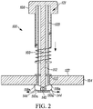
- FIG. 2 which illustrates the heat sink connector pin in an installed or engaged position, where the movable fingers 110a-110n are in an outwardly extended position so that at least a portion of the fingers extend beyond an edge of the opening and can contact a bottom surface of the substrate.
- the retracted position of the fingers in FIG. 1 allows frictionless insertion of the fingers through the opening 102, in this example a through-hole in the substrate 104.
- the second end is configured so that the fingers 110a and 111 are not deformed when they are passed through the through-hole thereby allowing a type of zero insertion force configuration. As illustrated in FIG.
- each of the movable fingers 110a and 110n include a substrate engagement surface 118a and 118n that are adapted to engage the bottom surface of the substrate 104 when they are in the outward extended position.
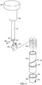
- the pin assembly includes a sleeve 120 that is adapted to receive the shaft structure 112.
- FIG. 3 illustrates a non-cylindrical shaft design that may be employed instead of a cylindrical design (shown in FIG. 4).
- FIG. 4 illustrates a cylindrical shaft and corresponding sleeve as illustrated in FIGs. 1 and 2 .
- the sleeve 120 is also adapted to engage with the pin head 108 by reciprocally sliding in an opening 121 (see FIG. 2 ) in the pin head 108 adapted to receive the sleeve 120.
- the sleeve 120 includes a substrate stop surface 122 shown in this example as a bottom surface of a substrate stop member 124.
- any suitable surface of the sleeve or other structure may be employed.
- the stop members 124 and 164 are shown as a disk structure that guides the shaft structure 112 however, there may be no need for a guide feature if the shaft structure does not need one nor do the stop members need to extend outwardly from the sleeve if desired.
- the substrate stop surface 122 is adapted to contact a top surface 127 of the substrate 104 during insertion of the second end 116 through the substrate opening 102.
- the pin head 108, sleeve 120, shaft 112, fingers 118a and 118n may be formed from plastic or any other suitable material.
- the sleeve 120 is made of multiple pieces that may be interconnected in any suitable manner such as snap fit, glue or in any suitable manner or may be a single piece if desired.
- the sleeve 120 includes a finger guide portion 126 which guides the fingers through the opening of the substrate.
- the finger guide portion 126 includes the substrate stop member 124 however the stop member 124 or any other portion of the sleeve providing the substrate stop surface 122 may be incorporated in any other suitable part of the sleeve 120 as desired.
- the finger guide portion 126 is cylindrical by may also be any suitable cross section or shape including conical to form a tapered tip for frictionless entry into the substrate opening.
- the shaft 112 may also be a single piece or made from multiple pieces as desired.
- the shaft 112 is attached to an interior of the pin head 108 for vertical (axial) movement but not rotational movement via a "C" clamp or other suitable structure inside the pin head 108 that receives the end of the shaft.
- attachment of the shaft may be done in any suitable manner.
- the sleeve 120 includes a threaded portion 130 and the pin head 108 includes a corresponding threaded portion 132 that is adapted to engage with the threaded portion 130 of the sleeve 120 to allow upward and downward movement of the pin head 108 with respect to the sleeve 120 in this example.
- any suitable structure may be employed other than a rotational mechanism to allow the pin head 108 to move in a downward motion causing the shaft 112 to move the movable fingers 110a and 110n in an outward position to engage a bottom surface of the substrate.
- the finger guide portion 126 receives the plurality of fingers 110a-110n, in this example through a channel 136 defined by the sleeve.
- the channel 136 also receives the shaft 112.
- the finger guide portion 126 includes finger slots 138 ( FIG. 3 ) that are configured to guide the plurality of movable fingers 110a-110n from moving from the retracted position to the outwardly extended position.
- finger slots may not be necessary depending on the design.
- the finger guide portion 126 includes a bottom 140 having a finger engagement surface 142 that is configured to contact a heel portion of a finger 144 and the curved portion of the heel makes contact with the bottom to force the fingers in an outward position.
- any other suitable mechanism may be employed to cause the fingers to expand outwardly to engage a bottom surface of the substrate.
- the plurality of movable fingers 110a-110n are rotatably connected to share a common axis shown as dashed line 148 which is a same rotational axis. In this example, this is accomplished using a pin 150 placed through corresponding openings in the shaft 112 shown as opening 152 and corresponding openings 154 in the fingers.
- any suitable connecting structure may be employed.
- the pin 150 may also be made from plastic, metal or any other suitable material.
- Other examples for connecting the fingers to rotate about an axis includes posts, or any other suitable engagement surfaces that connects the shaft 112 with the fingers so that the fingers rotatably move between a retracted position and extended position and share a same rotational axis. In another example, the rotational axis need not be shared if desired.
- a spring 160 serves as a compression spring that is configured around an outer surface of the sleeve 120.
- This spring 160 may not be necessary but can provide additional benefits such as allowing absorption during vibrations to cause the extended fingers 110a-110n ( FIG. 2 ) to be continuously forced against the bottom surface of the substrate 104.
- the spring 160 is not compressed, and as shown in FIG. 2 , the spring 160 is compressed through downward motion of the shaft 112 using the pin head 108 to push downwardly on the shaft 112.
- a rotational movement of the pin head 108 causes the threaded portion of the cap to move down the sleeve. The fingers are caused to pass through the finger guide portion 126.
- the fingers 110a-110n are then extended outward to grasp the bottom surface 129 of the substrate 104.
- the heels of the fingers contact the surface 142 pushing the fingers outward.
- the surface 142 may not be needed depending on the design as long as the fingers 110a-110n are caused to extend outwardly.
- the shape of the pin head 108 at the top of the pin head is shaped in a manner that allows a user to visually identify that the pin head 102 has been rotated thereby indicating proper installation. To remove the pin from a heat sink assembly, the pin head is rotated in the opposite direction.
- the shaft 112 is secured for vertical (axial) movement with pin head but not rotational movement via a "C" clamp or other suitable structure inside the pin head area that receives the end of the shaft.
- a "C” clamp or other suitable structure inside the pin head area that receives the end of the shaft.
- the cross section of the shaft 112 may be any suitable shape including cylindrical, square, conical or any suitable shape as desired.
- the fingers 110a and 110n may be any suitable shape as desired.
- the heat sink connector pin 100 in this example also includes a heat sink stop surface 162 to contact a surface of the heat sink such as a top portion of a heat sink arm (such arms as known in the art) such as arm 400 shown in FIG. 5 .
- the support surface 164 may also have a top surface 166 that supports the spring 160.
- the cap 108 includes a bottom surface 168 that serves as an opposing supporting surface for the spring to allow compression of the spring during downward movement of the cap 108.
- such support surfaces may not be needed where a spring is not employed or depending on the design of the heatsink.
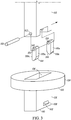
- a heat sink assembly 402 is shown illustrating the substrate 102 that supports a heat generating device 404 which in this example is shown to be a microprocessor, APU, GPU, or any other suitable integrated circuit.
- the integrated circuit is in a package that is also shown to be in a carrier 406 although any suitable heat dissipating device may benefit.
- a heat sink 408 is in thermal contact with the heat generating device 404 when placed in contact with the heat dissipating device through any suitable heat conducting members if a direct connection is not employed.
- the heat sink connector pins 100 are inserted through the through-holes 102 of the substrate and are configured to affix the heat sink 408 to the substrate 104.
- a fan assembly 410 is also shown to be affixed to the heat sink through attachment screws 412.
- the heat sink connector pins are of the type described above with reference to FIGs. 1 and 2 .
- one or more embodiments simplifies the installation experience and can improve installation time using a system that has bottom fingers that automatically grab onto the bottom of the substrate with little vertical compressive force.
- a user may simply insert the heat sink connector pin into the heat sink and substrate and rotate the pin head to engage the fingers to the bottom surface of the substrate and rotate the pin head on an opposite direction to remove retract the moveable fingers.
- Non rotational mechanisms may also be used.
- the operations described may be done in any suitable manner. It is therefore contemplated that the present embodiments cover any and all modifications, variations or equivalents that fall within the scope of the basic underlying principles disclosed above and claimed herein.
- the above description describes hardware in the form of a processor executing code, hardware in the form of a state machine or dedicated logic capable of producing the same effect, other structures are also contemplated.
Landscapes
- Engineering & Computer Science (AREA)
- General Engineering & Computer Science (AREA)
- Microelectronics & Electronic Packaging (AREA)
- Mechanical Engineering (AREA)
- Physics & Mathematics (AREA)
- Thermal Sciences (AREA)
- Cooling Or The Like Of Electrical Apparatus (AREA)
- Cooling Or The Like Of Semiconductors Or Solid State Devices (AREA)
- Theoretical Computer Science (AREA)
- Dowels (AREA)
- Mounting Components In General For Electric Apparatus (AREA)
- General Physics & Mathematics (AREA)
- Human Computer Interaction (AREA)
Description
- The disclosure relates to pins that are used to attach heat sinks to substrates that support heat dissipating devices such as microprocessors, memory or other electronic circuits.
- Electronic devices such as microprocessors, graphics processors, accelerated processing units or other electronic circuits may dissipate large amounts of heat when operating. The electronic devices are sometimes placed in sockets which are then soldered to substrates such as circuit boards. Heat sinks are then placed in thermal contact with outer surfaces of the device (such as the outer surface of the package) to draw heat away from the electronic device. Fans may also be employed as well in an attempt to keep the heat dissipating device cool.
- Heat sink attachment pins also referred to as connector pins are often used to attach the heat sink to the substrate when it is placed on top of or under the electronic device. Some heat sink connector pins include push pin designs that are effectively two piece designs that use a rod that is pushed through a hole down the center of the pin to push finger like push mechanisms in the through-hole of the substrate to mechanically engage with the interior of the through-hole. The separate locking rod or pin holds open the push fingers which form an engagement with the interior of the through-hole of the substrate. Push pins however can be manually intensive to insert and can be difficult to remove. Other designs may include single pieces of plastic that have a pin head and angled tip (arrow head) with barbs along with a spring placed around a shaft of the pin in an effort to provide downward force to keep the heat sink pressed against the electronic device. The angled tip is forced into the through-hole causing deformation of the tip and the barb is forced through the hole. The barb then expands after being forced through the through-hole and the pin is then fixedly engaged in the hole. Such designs can require unnecessary amounts of force to insert the pin and are also typically not removable. Problems also arise where the electronic device is fragile and forcing the angled tip through the hole of the substrate can unnecessarily cause damage to the electronic device and substrate. Also, to remove some pins, both the top and underside of the substrate have to be made accessible as such a machine or dissembler has to have access to both the top of the substrate and the bottom of the substrate.
- Other through-hole attachment mechanisms include a screw and a bolt combination that is screwed into a back plate or retention frame.
US 2011/194257 (Chen ) discloses a fixing device for fixing a first element to a second element, and a heat sink assembly using the fixing device. - Accordingly, it would be desirable to have an improved heat sink connector pin that overcomes one or more of the above problems.
- The disclosure will be more readily understood in view of the following description when accompanied by the below figures and wherein like reference numerals represent like elements, wherein:
-
FIG. 1 is a cross sectional view of one example of a connector pin in accordance with the disclosure; -
FIG. 2 is a cross sectional view of one example of a connector pin in accordance with the disclosure; -
FIG. 3 is an assembly view of another embodiment of a portion of the connector pin shown inFIG. 1 ; -
FIG. 4 is an assembly view of the connector pin shown inFIG. 1 ; and -
FIG. 5 is an assembly view illustrating one example of a heat sink assembly in accordance with the disclosure. - In one example, a heat sink connector pin includes a pin assembly with linkage that provides the movement of a pin head or cap in a downward movement to cause multiple movable fingers at an opposing end of the pin to move from a retracted position that allows insertion of the heat sink connector pin through an opening in the substrate, such as a through-hole, to mechanically move to an outward extended position so that the multiple fingers engage or grasp a bottom surface of the substrate. In one example, the pin head is rotatable in a twisting action to cause downward movement of a shaft structure to cause the fingers to move in an outward extended position to grasp the bottom surface of the substrate such as an integrated circuit socket or printed circuit board or any other suitable substrate. In other examples, any suitable force action may be employed other than a rotational or twisting motion that causes the shaft of the pin assembly to move in a downward motion to cause the fingers to move to a position to engage the bottom surface of the substrate.
- One or more advantages of the design includes, for example, a reduction in installation time and/or a reduction in the vertical force on a substrate reducing potential for hardware failure. In addition or alternatively, the heat sink connector pin may allow easier visual indication as to whether or not the pin is secured to the substrate and may only require access to a top surface of the substrate when inserting and removing the heat sink connector pin from a heat sink assembly.
- In one example, a heat sink connector pin for attaching a heatsink to a top surface of a substrate and in thermal contact with a heat generating device, includes a pin assembly having a pin head at a fist end and a plurality of moveable fingers at a second end. A shaft structure is operably engaged to the moveable fingers and to the pin head. The shaft structure is configured for downward movement, via rotational movement of pin head, pressing down on the pin head or any other suitable action causing downward movement of the shaft structure. In one example, the plurality of moveable fingers are configured to be in a retracted position that allows insertion of the second end through an opening in the substrate without deforming the plurality of movable fingers. The fingers are also configured to mechanically move outward to an extended position in a manner that positions the plurality of fingers to contact a bottom surface of the substrate, in response to downward movement of the shaft structure. The moveable fingers have a substrate engagement surface adapted to engage a bottom surface of the substrate when in the outward extended position.
- In one example, the plurality of movable fingers are rotatably connected to share a same rotational axis with each other. In one example, the pin assembly includes a sleeve adapted to receive the shaft structure and is adapted to engage with the pin head. The sleeve includes a substrate stop surface adapted to contact a top surface of the substrate during insertion of the second end through the substrate opening.
- In one example, the sleeve includes a threaded portion and the pin head includes a corresponding threaded portion adapted to engage with the threaded portion of the sleeve. In one example, the sleeve includes a finger guide portion adapted to receive the plurality of fingers. In one example, the finger guide portion includes finger slots configured to guide the plurality of moveable fingers when moving from the retracted position to the outwardly extended position. In one example, the finger guide includes a finger engagement surface configured to contact a heel portion of a finger.
- In one example, the heat sink connector pin includes a spring configured around the sleeve. In another example, a heat sink assembly includes the substrate that supports a heat generating device, the substrate defining at least one two through-holes. The heat sink assembly includes a heat sink in thermal contact with the heat generating device and a heat sink connector pin engaged with the heat sink and inserted through the through-hole of the substrate. The heat sink connector pin configured to affix the heat sink to the substrate. The heat sink connector pin being of a type set forth above. In one example the heat sink connector pin includes a pin assembly having a pin head at a fist end and a plurality of moveable fingers at a second end. A shaft structure is operably engaged to the moveable fingers and to the pin head. The shaft structure is configured for downward movement, via rotational movement of pin head, pressing down on the pin head or any other suitable action causing downward movement of the shaft structure. In one example, the plurality of moveable fingers are configured to be in a retracted position that allows insertion of the second end through an opening in the substrate without deforming the plurality of movable fingers. The fingers are also configured to mechanically move in an outward extended position in response to downward movement of the shaft structure that configures the fingers to contact a bottom surface of the substrate. The moveable fingers have a substrate engagement surface adapted to engage the bottom surface of the substrate when in the outward extended position.
- In one example, the plurality of movable fingers are rotatably connected to share a same rotational axis with each other. In one example, the pin assembly includes a sleeve adapted to receive the shaft structure and is adapted to engage with the pin head. The sleeve includes a substrate stop surface adapted to contact a top surface of the substrate during insertion of the second end through the substrate opening.
- In another example, sleeve includes a heat sink stop surface and a substrate stop surface, the substrate stop surface adapted to contact a top surface of the substrate during insertion of the second end through the substrate opening, and wherein each of the plurality of the movable fingers includes a substrate engagement surface adapted to engage a bottom surface of the substrate when in the outward extended position.
- In one example, two or more fingers serve as substrate bottom grips when they are extended in an outward position. Another surface of the pin assembly serves as a top side substrate stop surface so that a sleeve of the pin assembly does not pass through the through-hole and the movable fingers pass through in a retracted position and extend outwardly after passing through the opening in the substrate. If desired, a compression spring is used that provides downward pressure pushing the heat sink against the heat dissipating device and enhances shock absorption. In one example, the pin head is configured for a quarter turn or half turn causing the shaft to move in a downward position to cause the plurality of fingers to engage with the bottom of the substrate. In one example, the pin head has a shape so that the user can determine whether a heat sink connector pin is properly installed. Where a compression spring is employed, rotating or turning the pin head causes the compression of the spring which can further cause an upward force to be applied by the outwardly extended fingers, however any suitable structure may be employed.
-
FIG. 1 is a cross sectional view illustrating one example of a heatsink connector pin 100 that is being inserted through anopening 102 of asubstrate 104 such as a printed circuit board, chip carrier, or any other suitable substrate. Not shown is a heat sink (seeFIG. 5 ) which is connected to the substrate using the heatsink connector pin 100. In this example, a heatsink coupling portion 106 that engages with an arm of a heat sink is employed however, such a portion may not be necessary depending upon the design of the heat sink. For example, there would be no need if the heat sink does not include attachment arms and instead includes through-holes through another portion of the heat sink. The heatsink connector pin 100 in this example is configured as a pin assembly that includes apin head 108 at a first end of the pin assembly and a plurality ofmovable fingers 110a-110n that are located at a second end of the pin assembly. Ashaft structure 112 is engaged to the movable fingers and to the pin head for downward movement shown byarrow 114 as thepin head 108 moves downward. Movement of the pin head in a vertical or downward motion toward the substrate mechanically extends the fingers in an outward position in a manner that positions the plurality of fingers to contact a bottom surface of the substrate. - Referring also to
FIG. 2 which illustrates the heat sink connector pin in an installed or engaged position, where themovable fingers 110a-110n are in an outwardly extended position so that at least a portion of the fingers extend beyond an edge of the opening and can contact a bottom surface of the substrate. In contrast, the retracted position of the fingers inFIG. 1 allows frictionless insertion of the fingers through theopening 102, in this example a through-hole in thesubstrate 104. The second end is configured so that thefingers 110a and 111 are not deformed when they are passed through the through-hole thereby allowing a type of zero insertion force configuration. As illustrated inFIG. 2 , the plurality ofmovable fingers shaft structure 112 thereby engaging a bottom surface ofsubstrate 104 that is adjacent to the through-hole. In this example, each of themovable fingers substrate engagement surface substrate 104 when they are in the outward extended position. - Referring also to
FIG. 3 andFIG. 4 , the pin assembly includes asleeve 120 that is adapted to receive theshaft structure 112.FIG. 3 illustrates a non-cylindrical shaft design that may be employed instead of a cylindrical design (shown inFIG. 4). FIG. 4 illustrates a cylindrical shaft and corresponding sleeve as illustrated inFIGs. 1 and2 . Thesleeve 120 is also adapted to engage with thepin head 108 by reciprocally sliding in an opening 121 (seeFIG. 2 ) in thepin head 108 adapted to receive thesleeve 120. Thesleeve 120 includes asubstrate stop surface 122 shown in this example as a bottom surface of asubstrate stop member 124. However, any suitable surface of the sleeve or other structure may be employed. In this example thestop members shaft structure 112 however, there may be no need for a guide feature if the shaft structure does not need one nor do the stop members need to extend outwardly from the sleeve if desired. Thesubstrate stop surface 122 is adapted to contact atop surface 127 of thesubstrate 104 during insertion of thesecond end 116 through thesubstrate opening 102. - The
pin head 108,sleeve 120,shaft 112,fingers sleeve 120 is made of multiple pieces that may be interconnected in any suitable manner such as snap fit, glue or in any suitable manner or may be a single piece if desired. In this example, thesleeve 120 includes afinger guide portion 126 which guides the fingers through the opening of the substrate. In this example, thefinger guide portion 126 includes thesubstrate stop member 124 however thestop member 124 or any other portion of the sleeve providing thesubstrate stop surface 122 may be incorporated in any other suitable part of thesleeve 120 as desired. In the example shown inFIGS 1 ,2 and4 thefinger guide portion 126 is cylindrical by may also be any suitable cross section or shape including conical to form a tapered tip for frictionless entry into the substrate opening. - The
shaft 112 may also be a single piece or made from multiple pieces as desired. In this example, theshaft 112 is attached to an interior of thepin head 108 for vertical (axial) movement but not rotational movement via a "C" clamp or other suitable structure inside thepin head 108 that receives the end of the shaft. However, attachment of the shaft may be done in any suitable manner. - The
sleeve 120 includes a threadedportion 130 and thepin head 108 includes a corresponding threadedportion 132 that is adapted to engage with the threadedportion 130 of thesleeve 120 to allow upward and downward movement of thepin head 108 with respect to thesleeve 120 in this example. However, any suitable structure may be employed other than a rotational mechanism to allow thepin head 108 to move in a downward motion causing theshaft 112 to move themovable fingers finger guide portion 126 receives the plurality offingers 110a-110n, in this example through achannel 136 defined by the sleeve. Thechannel 136 also receives theshaft 112. In this example, thefinger guide portion 126 includes finger slots 138 (FIG. 3 ) that are configured to guide the plurality ofmovable fingers 110a-110n from moving from the retracted position to the outwardly extended position. However, such finger slots may not be necessary depending on the design. - In this example, the
finger guide portion 126 includes a bottom 140 having afinger engagement surface 142 that is configured to contact a heel portion of afinger 144 and the curved portion of the heel makes contact with the bottom to force the fingers in an outward position. However, any other suitable mechanism may be employed to cause the fingers to expand outwardly to engage a bottom surface of the substrate. The plurality ofmovable fingers 110a-110n are rotatably connected to share a common axis shown as dashed line 148 which is a same rotational axis. In this example, this is accomplished using apin 150 placed through corresponding openings in theshaft 112 shown asopening 152 andcorresponding openings 154 in the fingers. However, it will be recognized that any suitable connecting structure may be employed. Thepin 150 may also be made from plastic, metal or any other suitable material. Other examples for connecting the fingers to rotate about an axis includes posts, or any other suitable engagement surfaces that connects theshaft 112 with the fingers so that the fingers rotatably move between a retracted position and extended position and share a same rotational axis. In another example, the rotational axis need not be shared if desired. - As shown in
FIGs. 1 and2 , aspring 160 serves as a compression spring that is configured around an outer surface of thesleeve 120. Thisspring 160 may not be necessary but can provide additional benefits such as allowing absorption during vibrations to cause theextended fingers 110a-110n (FIG. 2 ) to be continuously forced against the bottom surface of thesubstrate 104. As shown inFIG. 1 , thespring 160 is not compressed, and as shown inFIG. 2 , thespring 160 is compressed through downward motion of theshaft 112 using thepin head 108 to push downwardly on theshaft 112. In this example, a rotational movement of thepin head 108 causes the threaded portion of the cap to move down the sleeve. The fingers are caused to pass through thefinger guide portion 126. Thefingers 110a-110n are then extended outward to grasp thebottom surface 129 of thesubstrate 104. In this example, the heels of the fingers contact thesurface 142 pushing the fingers outward. However, thesurface 142 may not be needed depending on the design as long as thefingers 110a-110n are caused to extend outwardly. Also in this example, the shape of thepin head 108 at the top of the pin head is shaped in a manner that allows a user to visually identify that thepin head 102 has been rotated thereby indicating proper installation. To remove the pin from a heat sink assembly, the pin head is rotated in the opposite direction. As noted above, theshaft 112 is secured for vertical (axial) movement with pin head but not rotational movement via a "C" clamp or other suitable structure inside the pin head area that receives the end of the shaft. When the rotational movement is reversed, the shaft has no force on it, and the fingers release the bottom of the substrate. With the outside spring compression, the fingers are forced back into the cylinder. - The cross section of the
shaft 112 may be any suitable shape including cylindrical, square, conical or any suitable shape as desired. Likewise, thefingers sink connector pin 100 in this example also includes a heatsink stop surface 162 to contact a surface of the heat sink such as a top portion of a heat sink arm (such arms as known in the art) such asarm 400 shown inFIG. 5 . Thesupport surface 164 may also have atop surface 166 that supports thespring 160. Also in this example, thecap 108 includes abottom surface 168 that serves as an opposing supporting surface for the spring to allow compression of the spring during downward movement of thecap 108. However, it will be recognized that such support surfaces may not be needed where a spring is not employed or depending on the design of the heatsink. - Referring also to
FIG. 5 , aheat sink assembly 402 is shown illustrating thesubstrate 102 that supports aheat generating device 404 which in this example is shown to be a microprocessor, APU, GPU, or any other suitable integrated circuit. In this example, the integrated circuit is in a package that is also shown to be in acarrier 406 although any suitable heat dissipating device may benefit. Aheat sink 408 is in thermal contact with theheat generating device 404 when placed in contact with the heat dissipating device through any suitable heat conducting members if a direct connection is not employed. The heat sink connector pins 100 are inserted through the through-holes 102 of the substrate and are configured to affix theheat sink 408 to thesubstrate 104. In this example, afan assembly 410 is also shown to be affixed to the heat sink through attachment screws 412. The heat sink connector pins are of the type described above with reference toFIGs. 1 and2 . - As described above one or more embodiments simplifies the installation experience and can improve installation time using a system that has bottom fingers that automatically grab onto the bottom of the substrate with little vertical compressive force. Where the pin head is rotatable, a user may simply insert the heat sink connector pin into the heat sink and substrate and rotate the pin head to engage the fingers to the bottom surface of the substrate and rotate the pin head on an opposite direction to remove retract the moveable fingers. Non rotational mechanisms may also be used.
For example, the operations described may be done in any suitable manner. It is therefore contemplated that the present embodiments cover any and all modifications, variations or equivalents that fall within the scope of the basic underlying principles disclosed above and claimed herein. Furthermore, while the above description describes hardware in the form of a processor executing code, hardware in the form of a state machine or dedicated logic capable of producing the same effect, other structures are also contemplated.
Claims (15)
- A heat sink connector pin (100) for attaching a heatsink to a top surface of a substrate and in thermal contact with a heat generating device, the pin comprising:
a pin assembly comprising a pin head (108) at a first end and a plurality of moveable fingers (110a-110n) at a second end, a shaft structure (112) operably engaged to the moveable fingers and to the pin head, the shaft structure configured for downward movement as the pin head moves downward, the plurality of moveable fingers configured to be in a retracted position that allows insertion of the second end through an opening in the substrate (104) without deforming the moveable fingers and configured to mechanically extend in an outward position in a manner that positions the plurality of fingers to contact a bottom surface (129) of the substrate (104), in response to downward movement of the shaft structure. - The heat sink connector pin as claimed in claim 1, wherein each of the plurality of the movable fingers comprises a substrate engagement surface (118a-118n) adapted to engage a bottom surface of the substrate when in the outward extended position.
- The heat sink connector pin as claimed in claim 1, wherein the plurality of movable fingers are rotatably connected to share a same rotational axis with each other.
- The heat sink connector pin as claimed in claim 1, wherein the pin assembly comprises a sleeve (120) adapted to receive the shaft structure and adapted to engage with the pin head and wherein the sleeve comprises a substrate stop surface (122) adapted to contact a top surface (127) of the substrate (104) during insertion of the second end (116) through the substrate opening (102).
- The heat sink connector pin as claimed in claim 4, wherein the sleeve comprises a threaded portion (130) and the pin head comprises a corresponding threaded portion (132) adapted to engage with the threaded portion of the sleeve and wherein the sleeve comprises a finger guide portion (126) adapted to receive the plurality of fingers and comprising finger slots (138) configured to guide the plurality of moveable fingers when moving from the retracted position to the outwardly extended position.
- The heat sink connector pin as claimed in claim 4, wherein the pin assembly comprises a spring (160) configured around the sleeve.
- The heat sink connector pin as claimed in claim 5, wherein the finger guide comprises a finger engagement surface (142) configured to contact a heel portion of a finger (144).
- The heat sink connector pin of claim 4, wherein said sleeve comprises a heat sink stop surface and wherein each of the plurality of the movable fingers comprises a substrate engagement surface adapted to engage a bottom surface of the substrate when in the outward extended position.
- The heat sink connector pin as claimed in claim 8, wherein the plurality of movable fingers are rotatably connected to share a same rotational axis with each other.
- The heat sink connector pin as claimed in claim 9, wherein the sleeve comprises a threaded portion and the pin head comprises a corresponding threaded portion adapted to engage with the threaded portion of the sleeve and wherein the sleeve comprises a finger guide portion adapted to receive the plurality of fingers and comprising channels (136) configured to guide the plurality of moveable fingers when moving from the retracted position to the outwardly extended position.
- The heat sink connector pin as claimed in claim 10, wherein the pin assembly comprises a spring configured around the sleeve.
- A heat sink assembly comprising:a substrate supporting a heat generating device (404), the substrate defining at least one through-hole;a heat sink (408), in thermal contact with the heat generating device;a heat sink connector pin (100) inserted through the through-hole (102) of the substrate and configured to affix the heat sink to the substrate, the heat sink connector pin comprising:
a pin head (108) at a first end and a plurality of moveable fingers (110a-110n) at a second end, a shaft structure (112) operably engaged to the moveable fingers and to the pin head, the shaft structure configured for downward movement as the pin head moves downward, the plurality of moveable fingers configured to be in a retracted position that allows insertion of the second end through the at least one through-hole in the substrate without deforming the moveable fingers and configured to mechanically extend in an outward position in a manner that positions the plurality of fingers to contact a bottom surface (129) of the substrate, in response to downward movement of the shaft structure. - The heat sink assembly as claimed in claim 12, wherein each of the plurality of the movable fingers comprises a substrate engagement surface adapted to engage a bottom surface of the substrate when in the outward extended position.
- The heat sink assembly as claimed in claim 12, wherein the plurality of movable fingers are rotatably connected to share a same rotational axis with each other.
- The heat sink assembly as claimed in claim 12, wherein the pin assembly comprises a sleeve adapted to receive the shaft structure and adapted to engage with the pin head and wherein the sleeve comprises a substrate stop surface adapted to contact a top surface of the substrate during insertion of the second end through the substrate opening.
Applications Claiming Priority (1)
| Application Number | Priority Date | Filing Date | Title |
|---|---|---|---|
| US15/362,064 US10117356B2 (en) | 2016-11-28 | 2016-11-28 | Heat sink connector pin and assembly |
Publications (2)
| Publication Number | Publication Date |
|---|---|
| EP3327770A1 EP3327770A1 (en) | 2018-05-30 |
| EP3327770B1 true EP3327770B1 (en) | 2019-03-06 |
Family
ID=57799449
Family Applications (1)
| Application Number | Title | Priority Date | Filing Date |
|---|---|---|---|
| EP16204147.9A Active EP3327770B1 (en) | 2016-11-28 | 2016-12-14 | Heat sink connector pin and assembly |
Country Status (6)
| Country | Link |
|---|---|
| US (1) | US10117356B2 (en) |
| EP (1) | EP3327770B1 (en) |
| JP (1) | JP7106536B2 (en) |
| KR (1) | KR102443652B1 (en) |
| CN (1) | CN109891581B (en) |
| WO (1) | WO2018098456A1 (en) |
Families Citing this family (3)
| Publication number | Priority date | Publication date | Assignee | Title |
|---|---|---|---|---|
| CN113251047A (en) * | 2021-04-29 | 2021-08-13 | 成都飞机工业(集团)有限责任公司 | Safety bolt capable of being operated on single side and use method thereof |
| US11758690B2 (en) * | 2021-06-18 | 2023-09-12 | Nanning Fulian Fugui Precision Industrial Co., Ltd. | Heat-dissipation device allowing easy detachment from heat-generating component |
| US12471221B2 (en) * | 2022-10-21 | 2025-11-11 | Raytheon Company | Clamping device with pivoting retainer |
Family Cites Families (22)
| Publication number | Priority date | Publication date | Assignee | Title |
|---|---|---|---|---|
| US4213642A (en) * | 1979-02-12 | 1980-07-22 | Hartwell Corporation | Rotary latch and method of operation |
| US4760495A (en) * | 1987-04-16 | 1988-07-26 | Prime Computer Inc. | Stand-off device |
| US5199733A (en) * | 1991-09-09 | 1993-04-06 | Delorme Glen E | Safety hitch pin |
| US5517734A (en) * | 1995-04-10 | 1996-05-21 | Korpi; John G. | Quick fastener |
| US5870286A (en) | 1997-08-20 | 1999-02-09 | International Business Machines Corporation | Heat sink assembly for cooling electronic modules |
| US6118659A (en) * | 1998-03-09 | 2000-09-12 | International Business Machines Corporation | Heat sink clamping spring additionally holding a ZIF socket locked |
| US6752577B2 (en) * | 2002-02-27 | 2004-06-22 | Shu-Chen Teng | Heat sink fastener |
| KR100457220B1 (en) | 2002-02-27 | 2004-11-16 | 잘만테크 주식회사 | Heat sink device for cooling chipset |
| JP3894070B2 (en) | 2002-08-06 | 2007-03-14 | 富士通株式会社 | Heat sink, heat sink device, fixing method of heat sink, and electronic device using the heat sink |
| US20040238947A1 (en) | 2003-05-28 | 2004-12-02 | Intel Corporation | Package and method for attaching an integrated heat spreader |
| US20050072558A1 (en) | 2003-10-03 | 2005-04-07 | Aavid Thermalloy, Llc | Heat sink assembly and connecting device |
| TWM248206U (en) * | 2003-10-17 | 2004-10-21 | Hon Hai Prec Ind Co Ltd | Clip for heat sink |
| US7516948B2 (en) * | 2004-04-02 | 2009-04-14 | Phd, Inc. | Pin clamp accessories |
| JP4212511B2 (en) * | 2004-05-06 | 2009-01-21 | 富士通株式会社 | Semiconductor device and method for assembling semiconductor device |
| US7489511B2 (en) * | 2006-12-28 | 2009-02-10 | Hon Hai Precision Industry Co., Ltd. | Heat sink clip |
| US7852633B2 (en) * | 2008-07-24 | 2010-12-14 | Yamaichi Electronics Co., Ltd. | Connector for connection to a module board |
| DE102009002992B4 (en) * | 2009-05-11 | 2014-10-30 | Infineon Technologies Ag | Power semiconductor module arrangement with unambiguously and torsionally mounted on a heat sink power semiconductor module and mounting method |
| JP3153773U (en) | 2009-07-08 | 2009-09-17 | 本俊 游 | Fixing member for heat dissipation module |
| JP2011023491A (en) | 2009-07-15 | 2011-02-03 | Nec Corp | Lock jig, and semiconductor device |
| US20110027038A1 (en) * | 2009-07-28 | 2011-02-03 | Pen-Chun YU | Heat sink anchoring apparatus |
| CN102146944A (en) | 2010-02-05 | 2011-08-10 | 鸿富锦精密工业(深圳)有限公司 | Fixing device and heat radiation module using same |
| KR101508467B1 (en) | 2014-09-23 | 2015-04-07 | 삼성전기주식회사 | Semicoductor Module for Combining Heat Sink |
-
2016
- 2016-11-28 US US15/362,064 patent/US10117356B2/en active Active
- 2016-12-14 EP EP16204147.9A patent/EP3327770B1/en active Active
-
2017
- 2017-11-28 CN CN201780066991.5A patent/CN109891581B/en active Active
- 2017-11-28 JP JP2019528492A patent/JP7106536B2/en active Active
- 2017-11-28 KR KR1020197012083A patent/KR102443652B1/en active Active
- 2017-11-28 WO PCT/US2017/063367 patent/WO2018098456A1/en not_active Ceased
Non-Patent Citations (1)
| Title |
|---|
| None * |
Also Published As
| Publication number | Publication date |
|---|---|
| JP2020501354A (en) | 2020-01-16 |
| EP3327770A1 (en) | 2018-05-30 |
| JP7106536B2 (en) | 2022-07-26 |
| KR20190082204A (en) | 2019-07-09 |
| WO2018098456A1 (en) | 2018-05-31 |
| CN109891581A (en) | 2019-06-14 |
| US10117356B2 (en) | 2018-10-30 |
| US20180150114A1 (en) | 2018-05-31 |
| CN109891581B (en) | 2022-12-30 |
| KR102443652B1 (en) | 2022-09-15 |
Similar Documents
| Publication | Publication Date | Title |
|---|---|---|
| US7180743B2 (en) | Fastener for heat sink | |
| US7283368B2 (en) | Heat dissipating assembly | |
| US6611431B1 (en) | Heat dissipation assembly | |
| US20070217159A1 (en) | Clip assembly for attaching a heat sink to an electronic device | |
| EP3327770B1 (en) | Heat sink connector pin and assembly | |
| US20060262506A1 (en) | Heat sink assembly | |
| CN1848035A (en) | Locking module | |
| US7817427B2 (en) | Fastener and heat sink assembly having the same | |
| US8422233B2 (en) | Motherboard system having heat dissipating device | |
| CN101825937A (en) | Radiating device | |
| US20110157831A1 (en) | Locking structure and method for manufacturing the same and heat dissipation device using the same | |
| CN101541155A (en) | Heat dissipating combination | |
| US20100307997A1 (en) | Mounting pack structure and mounting hole adapter thereof | |
| US20060067053A1 (en) | Locking device for heat dissipating device | |
| US20080158828A1 (en) | Heatsink structure and assembly fixture thereof | |
| US20090120613A1 (en) | Heat sink | |
| US9917033B2 (en) | Multicomponent heat sink with movable fin support portion | |
| US9711431B2 (en) | Adjustable fastening bracket for radiator | |
| US20110108234A1 (en) | Fastening device and heat dissipation apparatus using the same | |
| US20170034952A1 (en) | Fixture device for heat-dissipating module and heat-dissipating module having fixture device | |
| CN101309569A (en) | Fastener and combination of cooling device | |
| KR20210033170A (en) | Heat sink combining structure | |
| US7405938B2 (en) | Heat sink clip | |
| US6822870B2 (en) | Retaining apparatus | |
| US20130037238A1 (en) | Fasteners and heat dissipation devices with the fasteners |
Legal Events
| Date | Code | Title | Description |
|---|---|---|---|
| STAA | Information on the status of an ep patent application or granted ep patent |
Free format text: STATUS: EXAMINATION IS IN PROGRESS |
|
| PUAI | Public reference made under article 153(3) epc to a published international application that has entered the european phase |
Free format text: ORIGINAL CODE: 0009012 |
|
| 17P | Request for examination filed |
Effective date: 20161214 |
|
| AK | Designated contracting states |
Kind code of ref document: A1 Designated state(s): AL AT BE BG CH CY CZ DE DK EE ES FI FR GB GR HR HU IE IS IT LI LT LU LV MC MK MT NL NO PL PT RO RS SE SI SK SM TR |
|
| AX | Request for extension of the european patent |
Extension state: BA ME |
|
| GRAP | Despatch of communication of intention to grant a patent |
Free format text: ORIGINAL CODE: EPIDOSNIGR1 |
|
| STAA | Information on the status of an ep patent application or granted ep patent |
Free format text: STATUS: GRANT OF PATENT IS INTENDED |
|
| RIC1 | Information provided on ipc code assigned before grant |
Ipc: F16B 21/12 20060101ALN20181005BHEP Ipc: F16B 19/10 20060101ALI20181005BHEP Ipc: F16B 5/02 20060101ALI20181005BHEP Ipc: H05K 7/20 20060101ALI20181005BHEP Ipc: H01L 23/40 20060101AFI20181005BHEP Ipc: H05K 1/02 20060101ALI20181005BHEP |
|
| INTG | Intention to grant announced |
Effective date: 20181029 |
|
| GRAS | Grant fee paid |
Free format text: ORIGINAL CODE: EPIDOSNIGR3 |
|
| GRAA | (expected) grant |
Free format text: ORIGINAL CODE: 0009210 |
|
| STAA | Information on the status of an ep patent application or granted ep patent |
Free format text: STATUS: THE PATENT HAS BEEN GRANTED |
|
| AK | Designated contracting states |
Kind code of ref document: B1 Designated state(s): AL AT BE BG CH CY CZ DE DK EE ES FI FR GB GR HR HU IE IS IT LI LT LU LV MC MK MT NL NO PL PT RO RS SE SI SK SM TR |
|
| REG | Reference to a national code |
Ref country code: GB Ref legal event code: FG4D |
|
| REG | Reference to a national code |
Ref country code: CH Ref legal event code: EP Ref country code: AT Ref legal event code: REF Ref document number: 1105694 Country of ref document: AT Kind code of ref document: T Effective date: 20190315 |
|
| REG | Reference to a national code |
Ref country code: DE Ref legal event code: R096 Ref document number: 602016010672 Country of ref document: DE |
|
| REG | Reference to a national code |
Ref country code: IE Ref legal event code: FG4D |
|
| REG | Reference to a national code |
Ref country code: NL Ref legal event code: MP Effective date: 20190306 |
|
| REG | Reference to a national code |
Ref country code: LT Ref legal event code: MG4D |
|
| PG25 | Lapsed in a contracting state [announced via postgrant information from national office to epo] |
Ref country code: FI Free format text: LAPSE BECAUSE OF FAILURE TO SUBMIT A TRANSLATION OF THE DESCRIPTION OR TO PAY THE FEE WITHIN THE PRESCRIBED TIME-LIMIT Effective date: 20190306 Ref country code: LT Free format text: LAPSE BECAUSE OF FAILURE TO SUBMIT A TRANSLATION OF THE DESCRIPTION OR TO PAY THE FEE WITHIN THE PRESCRIBED TIME-LIMIT Effective date: 20190306 Ref country code: NO Free format text: LAPSE BECAUSE OF FAILURE TO SUBMIT A TRANSLATION OF THE DESCRIPTION OR TO PAY THE FEE WITHIN THE PRESCRIBED TIME-LIMIT Effective date: 20190606 Ref country code: SE Free format text: LAPSE BECAUSE OF FAILURE TO SUBMIT A TRANSLATION OF THE DESCRIPTION OR TO PAY THE FEE WITHIN THE PRESCRIBED TIME-LIMIT Effective date: 20190306 |
|
| PG25 | Lapsed in a contracting state [announced via postgrant information from national office to epo] |
Ref country code: NL Free format text: LAPSE BECAUSE OF FAILURE TO SUBMIT A TRANSLATION OF THE DESCRIPTION OR TO PAY THE FEE WITHIN THE PRESCRIBED TIME-LIMIT Effective date: 20190306 Ref country code: RS Free format text: LAPSE BECAUSE OF FAILURE TO SUBMIT A TRANSLATION OF THE DESCRIPTION OR TO PAY THE FEE WITHIN THE PRESCRIBED TIME-LIMIT Effective date: 20190306 Ref country code: LV Free format text: LAPSE BECAUSE OF FAILURE TO SUBMIT A TRANSLATION OF THE DESCRIPTION OR TO PAY THE FEE WITHIN THE PRESCRIBED TIME-LIMIT Effective date: 20190306 Ref country code: BG Free format text: LAPSE BECAUSE OF FAILURE TO SUBMIT A TRANSLATION OF THE DESCRIPTION OR TO PAY THE FEE WITHIN THE PRESCRIBED TIME-LIMIT Effective date: 20190606 Ref country code: GR Free format text: LAPSE BECAUSE OF FAILURE TO SUBMIT A TRANSLATION OF THE DESCRIPTION OR TO PAY THE FEE WITHIN THE PRESCRIBED TIME-LIMIT Effective date: 20190607 Ref country code: HR Free format text: LAPSE BECAUSE OF FAILURE TO SUBMIT A TRANSLATION OF THE DESCRIPTION OR TO PAY THE FEE WITHIN THE PRESCRIBED TIME-LIMIT Effective date: 20190306 |
|
| REG | Reference to a national code |
Ref country code: AT Ref legal event code: MK05 Ref document number: 1105694 Country of ref document: AT Kind code of ref document: T Effective date: 20190306 |
|
| PG25 | Lapsed in a contracting state [announced via postgrant information from national office to epo] |
Ref country code: EE Free format text: LAPSE BECAUSE OF FAILURE TO SUBMIT A TRANSLATION OF THE DESCRIPTION OR TO PAY THE FEE WITHIN THE PRESCRIBED TIME-LIMIT Effective date: 20190306 Ref country code: SK Free format text: LAPSE BECAUSE OF FAILURE TO SUBMIT A TRANSLATION OF THE DESCRIPTION OR TO PAY THE FEE WITHIN THE PRESCRIBED TIME-LIMIT Effective date: 20190306 Ref country code: PT Free format text: LAPSE BECAUSE OF FAILURE TO SUBMIT A TRANSLATION OF THE DESCRIPTION OR TO PAY THE FEE WITHIN THE PRESCRIBED TIME-LIMIT Effective date: 20190706 Ref country code: AL Free format text: LAPSE BECAUSE OF FAILURE TO SUBMIT A TRANSLATION OF THE DESCRIPTION OR TO PAY THE FEE WITHIN THE PRESCRIBED TIME-LIMIT Effective date: 20190306 Ref country code: IT Free format text: LAPSE BECAUSE OF FAILURE TO SUBMIT A TRANSLATION OF THE DESCRIPTION OR TO PAY THE FEE WITHIN THE PRESCRIBED TIME-LIMIT Effective date: 20190306 Ref country code: ES Free format text: LAPSE BECAUSE OF FAILURE TO SUBMIT A TRANSLATION OF THE DESCRIPTION OR TO PAY THE FEE WITHIN THE PRESCRIBED TIME-LIMIT Effective date: 20190306 Ref country code: RO Free format text: LAPSE BECAUSE OF FAILURE TO SUBMIT A TRANSLATION OF THE DESCRIPTION OR TO PAY THE FEE WITHIN THE PRESCRIBED TIME-LIMIT Effective date: 20190306 Ref country code: CZ Free format text: LAPSE BECAUSE OF FAILURE TO SUBMIT A TRANSLATION OF THE DESCRIPTION OR TO PAY THE FEE WITHIN THE PRESCRIBED TIME-LIMIT Effective date: 20190306 |
|
| PG25 | Lapsed in a contracting state [announced via postgrant information from national office to epo] |
Ref country code: SM Free format text: LAPSE BECAUSE OF FAILURE TO SUBMIT A TRANSLATION OF THE DESCRIPTION OR TO PAY THE FEE WITHIN THE PRESCRIBED TIME-LIMIT Effective date: 20190306 Ref country code: PL Free format text: LAPSE BECAUSE OF FAILURE TO SUBMIT A TRANSLATION OF THE DESCRIPTION OR TO PAY THE FEE WITHIN THE PRESCRIBED TIME-LIMIT Effective date: 20190306 |
|
| REG | Reference to a national code |
Ref country code: DE Ref legal event code: R097 Ref document number: 602016010672 Country of ref document: DE |
|
| PG25 | Lapsed in a contracting state [announced via postgrant information from national office to epo] |
Ref country code: AT Free format text: LAPSE BECAUSE OF FAILURE TO SUBMIT A TRANSLATION OF THE DESCRIPTION OR TO PAY THE FEE WITHIN THE PRESCRIBED TIME-LIMIT Effective date: 20190306 Ref country code: IS Free format text: LAPSE BECAUSE OF FAILURE TO SUBMIT A TRANSLATION OF THE DESCRIPTION OR TO PAY THE FEE WITHIN THE PRESCRIBED TIME-LIMIT Effective date: 20190706 |
|
| PLBE | No opposition filed within time limit |
Free format text: ORIGINAL CODE: 0009261 |
|
| STAA | Information on the status of an ep patent application or granted ep patent |
Free format text: STATUS: NO OPPOSITION FILED WITHIN TIME LIMIT |
|
| PG25 | Lapsed in a contracting state [announced via postgrant information from national office to epo] |
Ref country code: DK Free format text: LAPSE BECAUSE OF FAILURE TO SUBMIT A TRANSLATION OF THE DESCRIPTION OR TO PAY THE FEE WITHIN THE PRESCRIBED TIME-LIMIT Effective date: 20190306 |
|
| 26N | No opposition filed |
Effective date: 20191209 |
|
| PG25 | Lapsed in a contracting state [announced via postgrant information from national office to epo] |
Ref country code: TR Free format text: LAPSE BECAUSE OF FAILURE TO SUBMIT A TRANSLATION OF THE DESCRIPTION OR TO PAY THE FEE WITHIN THE PRESCRIBED TIME-LIMIT Effective date: 20190306 |
|
| REG | Reference to a national code |
Ref country code: CH Ref legal event code: PL |
|
| REG | Reference to a national code |
Ref country code: BE Ref legal event code: MM Effective date: 20191231 |
|
| PG25 | Lapsed in a contracting state [announced via postgrant information from national office to epo] |
Ref country code: MC Free format text: LAPSE BECAUSE OF FAILURE TO SUBMIT A TRANSLATION OF THE DESCRIPTION OR TO PAY THE FEE WITHIN THE PRESCRIBED TIME-LIMIT Effective date: 20190306 |
|
| PG25 | Lapsed in a contracting state [announced via postgrant information from national office to epo] |
Ref country code: FR Free format text: LAPSE BECAUSE OF NON-PAYMENT OF DUE FEES Effective date: 20191231 Ref country code: LU Free format text: LAPSE BECAUSE OF NON-PAYMENT OF DUE FEES Effective date: 20191214 Ref country code: IE Free format text: LAPSE BECAUSE OF NON-PAYMENT OF DUE FEES Effective date: 20191214 |
|
| PG25 | Lapsed in a contracting state [announced via postgrant information from national office to epo] |
Ref country code: BE Free format text: LAPSE BECAUSE OF NON-PAYMENT OF DUE FEES Effective date: 20191231 Ref country code: LI Free format text: LAPSE BECAUSE OF NON-PAYMENT OF DUE FEES Effective date: 20191231 Ref country code: CH Free format text: LAPSE BECAUSE OF NON-PAYMENT OF DUE FEES Effective date: 20191231 |
|
| PG25 | Lapsed in a contracting state [announced via postgrant information from national office to epo] |
Ref country code: CY Free format text: LAPSE BECAUSE OF FAILURE TO SUBMIT A TRANSLATION OF THE DESCRIPTION OR TO PAY THE FEE WITHIN THE PRESCRIBED TIME-LIMIT Effective date: 20190306 |
|
| PG25 | Lapsed in a contracting state [announced via postgrant information from national office to epo] |
Ref country code: HU Free format text: LAPSE BECAUSE OF FAILURE TO SUBMIT A TRANSLATION OF THE DESCRIPTION OR TO PAY THE FEE WITHIN THE PRESCRIBED TIME-LIMIT; INVALID AB INITIO Effective date: 20161214 Ref country code: MT Free format text: LAPSE BECAUSE OF FAILURE TO SUBMIT A TRANSLATION OF THE DESCRIPTION OR TO PAY THE FEE WITHIN THE PRESCRIBED TIME-LIMIT Effective date: 20190306 |
|
| PG25 | Lapsed in a contracting state [announced via postgrant information from national office to epo] |
Ref country code: SI Free format text: LAPSE BECAUSE OF FAILURE TO SUBMIT A TRANSLATION OF THE DESCRIPTION OR TO PAY THE FEE WITHIN THE PRESCRIBED TIME-LIMIT Effective date: 20190306 |
|
| PG25 | Lapsed in a contracting state [announced via postgrant information from national office to epo] |
Ref country code: MK Free format text: LAPSE BECAUSE OF FAILURE TO SUBMIT A TRANSLATION OF THE DESCRIPTION OR TO PAY THE FEE WITHIN THE PRESCRIBED TIME-LIMIT Effective date: 20190306 |
|
| P01 | Opt-out of the competence of the unified patent court (upc) registered |
Effective date: 20230530 |
|
| REG | Reference to a national code |
Ref country code: DE Ref legal event code: R079 Ref document number: 602016010672 Country of ref document: DE Free format text: PREVIOUS MAIN CLASS: H01L0023400000 Ipc: H10W0040600000 |
|
| PGFP | Annual fee paid to national office [announced via postgrant information from national office to epo] |
Ref country code: DE Payment date: 20251113 Year of fee payment: 10 |
|
| PGFP | Annual fee paid to national office [announced via postgrant information from national office to epo] |
Ref country code: GB Payment date: 20251203 Year of fee payment: 10 |