EP3327725A1 - Running analysis device, running analysis method and running analysis program - Google Patents
Running analysis device, running analysis method and running analysis program Download PDFInfo
- Publication number
- EP3327725A1 EP3327725A1 EP17193464.9A EP17193464A EP3327725A1 EP 3327725 A1 EP3327725 A1 EP 3327725A1 EP 17193464 A EP17193464 A EP 17193464A EP 3327725 A1 EP3327725 A1 EP 3327725A1
- Authority
- EP
- European Patent Office
- Prior art keywords
- period
- running
- user
- indicator
- timing
- Prior art date
- Legal status (The legal status is an assumption and is not a legal conclusion. Google has not performed a legal analysis and makes no representation as to the accuracy of the status listed.)
- Granted
Links
- 238000004458 analytical method Methods 0.000 title claims abstract description 48
- 230000001133 acceleration Effects 0.000 claims description 40
- 238000000034 method Methods 0.000 claims description 11
- 239000000284 extract Substances 0.000 claims description 2
- 238000012549 training Methods 0.000 description 8
- 238000004891 communication Methods 0.000 description 7
- 238000010586 diagram Methods 0.000 description 4
- 238000005070 sampling Methods 0.000 description 3
- 238000005401 electroluminescence Methods 0.000 description 2
- 230000003247 decreasing effect Effects 0.000 description 1
- 238000011156 evaluation Methods 0.000 description 1
- 230000005484 gravity Effects 0.000 description 1
- 230000009191 jumping Effects 0.000 description 1
- 239000004973 liquid crystal related substance Substances 0.000 description 1
- 238000005259 measurement Methods 0.000 description 1
- 238000012545 processing Methods 0.000 description 1
Images


Classifications
-
- A—HUMAN NECESSITIES
- A63—SPORTS; GAMES; AMUSEMENTS
- A63B—APPARATUS FOR PHYSICAL TRAINING, GYMNASTICS, SWIMMING, CLIMBING, OR FENCING; BALL GAMES; TRAINING EQUIPMENT
- A63B71/00—Games or sports accessories not covered in groups A63B1/00 - A63B69/00
- A63B71/06—Indicating or scoring devices for games or players, or for other sports activities
- A63B71/0605—Decision makers and devices using detection means facilitating arbitration
-
- A—HUMAN NECESSITIES
- A63—SPORTS; GAMES; AMUSEMENTS
- A63B—APPARATUS FOR PHYSICAL TRAINING, GYMNASTICS, SWIMMING, CLIMBING, OR FENCING; BALL GAMES; TRAINING EQUIPMENT
- A63B24/00—Electric or electronic controls for exercising apparatus of preceding groups; Controlling or monitoring of exercises, sportive games, training or athletic performances
- A63B24/0003—Analysing the course of a movement or motion sequences during an exercise or trainings sequence, e.g. swing for golf or tennis
- A63B24/0006—Computerised comparison for qualitative assessment of motion sequences or the course of a movement
-
- A—HUMAN NECESSITIES
- A61—MEDICAL OR VETERINARY SCIENCE; HYGIENE
- A61B—DIAGNOSIS; SURGERY; IDENTIFICATION
- A61B5/00—Measuring for diagnostic purposes; Identification of persons
- A61B5/103—Detecting, measuring or recording devices for testing the shape, pattern, colour, size or movement of the body or parts thereof, for diagnostic purposes
- A61B5/11—Measuring movement of the entire body or parts thereof, e.g. head or hand tremor, mobility of a limb
- A61B5/112—Gait analysis
-
- A—HUMAN NECESSITIES
- A63—SPORTS; GAMES; AMUSEMENTS
- A63B—APPARATUS FOR PHYSICAL TRAINING, GYMNASTICS, SWIMMING, CLIMBING, OR FENCING; BALL GAMES; TRAINING EQUIPMENT
- A63B24/00—Electric or electronic controls for exercising apparatus of preceding groups; Controlling or monitoring of exercises, sportive games, training or athletic performances
- A63B24/0062—Monitoring athletic performances, e.g. for determining the work of a user on an exercise apparatus, the completed jogging or cycling distance
-
- A—HUMAN NECESSITIES
- A63—SPORTS; GAMES; AMUSEMENTS
- A63B—APPARATUS FOR PHYSICAL TRAINING, GYMNASTICS, SWIMMING, CLIMBING, OR FENCING; BALL GAMES; TRAINING EQUIPMENT
- A63B69/00—Training appliances or apparatus for special sports
- A63B69/0028—Training appliances or apparatus for special sports for running, jogging or speed-walking
-
- A—HUMAN NECESSITIES
- A63—SPORTS; GAMES; AMUSEMENTS
- A63B—APPARATUS FOR PHYSICAL TRAINING, GYMNASTICS, SWIMMING, CLIMBING, OR FENCING; BALL GAMES; TRAINING EQUIPMENT
- A63B71/00—Games or sports accessories not covered in groups A63B1/00 - A63B69/00
- A63B71/06—Indicating or scoring devices for games or players, or for other sports activities
- A63B71/0619—Displays, user interfaces and indicating devices, specially adapted for sport equipment, e.g. display mounted on treadmills
- A63B71/0622—Visual, audio or audio-visual systems for entertaining, instructing or motivating the user
-
- G—PHYSICS
- G06—COMPUTING; CALCULATING OR COUNTING
- G06V—IMAGE OR VIDEO RECOGNITION OR UNDERSTANDING
- G06V40/00—Recognition of biometric, human-related or animal-related patterns in image or video data
- G06V40/20—Movements or behaviour, e.g. gesture recognition
- G06V40/23—Recognition of whole body movements, e.g. for sport training
- G06V40/25—Recognition of walking or running movements, e.g. gait recognition
-
- G—PHYSICS
- G16—INFORMATION AND COMMUNICATION TECHNOLOGY [ICT] SPECIALLY ADAPTED FOR SPECIFIC APPLICATION FIELDS
- G16H—HEALTHCARE INFORMATICS, i.e. INFORMATION AND COMMUNICATION TECHNOLOGY [ICT] SPECIALLY ADAPTED FOR THE HANDLING OR PROCESSING OF MEDICAL OR HEALTHCARE DATA
- G16H20/00—ICT specially adapted for therapies or health-improving plans, e.g. for handling prescriptions, for steering therapy or for monitoring patient compliance
- G16H20/30—ICT specially adapted for therapies or health-improving plans, e.g. for handling prescriptions, for steering therapy or for monitoring patient compliance relating to physical therapies or activities, e.g. physiotherapy, acupressure or exercising
-
- G—PHYSICS
- G16—INFORMATION AND COMMUNICATION TECHNOLOGY [ICT] SPECIALLY ADAPTED FOR SPECIFIC APPLICATION FIELDS
- G16H—HEALTHCARE INFORMATICS, i.e. INFORMATION AND COMMUNICATION TECHNOLOGY [ICT] SPECIALLY ADAPTED FOR THE HANDLING OR PROCESSING OF MEDICAL OR HEALTHCARE DATA
- G16H40/00—ICT specially adapted for the management or administration of healthcare resources or facilities; ICT specially adapted for the management or operation of medical equipment or devices
- G16H40/60—ICT specially adapted for the management or administration of healthcare resources or facilities; ICT specially adapted for the management or operation of medical equipment or devices for the operation of medical equipment or devices
- G16H40/63—ICT specially adapted for the management or administration of healthcare resources or facilities; ICT specially adapted for the management or operation of medical equipment or devices for the operation of medical equipment or devices for local operation
-
- A—HUMAN NECESSITIES
- A61—MEDICAL OR VETERINARY SCIENCE; HYGIENE
- A61B—DIAGNOSIS; SURGERY; IDENTIFICATION
- A61B2562/00—Details of sensors; Constructional details of sensor housings or probes; Accessories for sensors
- A61B2562/02—Details of sensors specially adapted for in-vivo measurements
- A61B2562/0219—Inertial sensors, e.g. accelerometers, gyroscopes, tilt switches
-
- A—HUMAN NECESSITIES
- A63—SPORTS; GAMES; AMUSEMENTS
- A63B—APPARATUS FOR PHYSICAL TRAINING, GYMNASTICS, SWIMMING, CLIMBING, OR FENCING; BALL GAMES; TRAINING EQUIPMENT
- A63B24/00—Electric or electronic controls for exercising apparatus of preceding groups; Controlling or monitoring of exercises, sportive games, training or athletic performances
- A63B24/0003—Analysing the course of a movement or motion sequences during an exercise or trainings sequence, e.g. swing for golf or tennis
- A63B24/0006—Computerised comparison for qualitative assessment of motion sequences or the course of a movement
- A63B2024/0009—Computerised real time comparison with previous movements or motion sequences of the user
-
- A—HUMAN NECESSITIES
- A63—SPORTS; GAMES; AMUSEMENTS
- A63B—APPARATUS FOR PHYSICAL TRAINING, GYMNASTICS, SWIMMING, CLIMBING, OR FENCING; BALL GAMES; TRAINING EQUIPMENT
- A63B71/00—Games or sports accessories not covered in groups A63B1/00 - A63B69/00
- A63B71/06—Indicating or scoring devices for games or players, or for other sports activities
- A63B71/0619—Displays, user interfaces and indicating devices, specially adapted for sport equipment, e.g. display mounted on treadmills
- A63B2071/0658—Position or arrangement of display
- A63B2071/0661—Position or arrangement of display arranged on the user
-
- A—HUMAN NECESSITIES
- A63—SPORTS; GAMES; AMUSEMENTS
- A63B—APPARATUS FOR PHYSICAL TRAINING, GYMNASTICS, SWIMMING, CLIMBING, OR FENCING; BALL GAMES; TRAINING EQUIPMENT
- A63B2220/00—Measuring of physical parameters relating to sporting activity
- A63B2220/30—Speed
- A63B2220/34—Angular speed
-
- A—HUMAN NECESSITIES
- A63—SPORTS; GAMES; AMUSEMENTS
- A63B—APPARATUS FOR PHYSICAL TRAINING, GYMNASTICS, SWIMMING, CLIMBING, OR FENCING; BALL GAMES; TRAINING EQUIPMENT
- A63B2220/00—Measuring of physical parameters relating to sporting activity
- A63B2220/40—Acceleration
-
- A—HUMAN NECESSITIES
- A63—SPORTS; GAMES; AMUSEMENTS
- A63B—APPARATUS FOR PHYSICAL TRAINING, GYMNASTICS, SWIMMING, CLIMBING, OR FENCING; BALL GAMES; TRAINING EQUIPMENT
- A63B2220/00—Measuring of physical parameters relating to sporting activity
- A63B2220/62—Time or time measurement used for time reference, time stamp, master time or clock signal
-
- A—HUMAN NECESSITIES
- A63—SPORTS; GAMES; AMUSEMENTS
- A63B—APPARATUS FOR PHYSICAL TRAINING, GYMNASTICS, SWIMMING, CLIMBING, OR FENCING; BALL GAMES; TRAINING EQUIPMENT
- A63B2220/00—Measuring of physical parameters relating to sporting activity
- A63B2220/80—Special sensors, transducers or devices therefor
- A63B2220/803—Motion sensors
-
- A—HUMAN NECESSITIES
- A63—SPORTS; GAMES; AMUSEMENTS
- A63B—APPARATUS FOR PHYSICAL TRAINING, GYMNASTICS, SWIMMING, CLIMBING, OR FENCING; BALL GAMES; TRAINING EQUIPMENT
- A63B2220/00—Measuring of physical parameters relating to sporting activity
- A63B2220/80—Special sensors, transducers or devices therefor
- A63B2220/83—Special sensors, transducers or devices therefor characterised by the position of the sensor
- A63B2220/836—Sensors arranged on the body of the user
-
- A—HUMAN NECESSITIES
- A63—SPORTS; GAMES; AMUSEMENTS
- A63B—APPARATUS FOR PHYSICAL TRAINING, GYMNASTICS, SWIMMING, CLIMBING, OR FENCING; BALL GAMES; TRAINING EQUIPMENT
- A63B2225/00—Miscellaneous features of sport apparatus, devices or equipment
- A63B2225/50—Wireless data transmission, e.g. by radio transmitters or telemetry
-
- G—PHYSICS
- G06—COMPUTING; CALCULATING OR COUNTING
- G06F—ELECTRIC DIGITAL DATA PROCESSING
- G06F2218/00—Aspects of pattern recognition specially adapted for signal processing
- G06F2218/12—Classification; Matching
Definitions
- the present invention relates to a running analysis device, a running analysis method and a running analysis program.
- a measurement device which can obtain, from output results of an acceleration sensor in the moving direction and the vertical direction when a person walks with the acceleration sensor attached, data relevant to a landing timing(s), a ground leaving timing(s) and a ground contact time(s) during the walk, for example.
- the data relevant to the landing timing, the ground leaving timing and the ground contact time are utilized for running analysis, and it is considered, for example, that reducing the ground contact time can increase the running speed.
- reducing the ground contact time(s) without changing a stride(s) merely changes a component ratio of the stride and does not directly contribute to increase in the running speed. That is, only reducing the ground contact time is not enough as an indicator for increasing the running speed.
- the running speed can be increased if a ground contact time rate in a running cycle can be reduced without reducing a stance phase stride of the stride. That is, if a hang time(s) is extended while the step frequency is kept, the ground contact time rate is reduced.
- a new evaluation indicator(s) that is effective in stride lengthening.
- the present invention has been conceived in view of the above problems, and objects of the present invention include providing a running analysis device, a running analysis method and a running analysis program each of which can identify an indicator(s) for increasing the running speed.
- a running analysis device including: an analyzer that analyzes running of a user using sensor data output from a sensor attached to the user, wherein the analyzer includes an indicator identifying unit that identifies, in a swing phase in a running cycle, a period that serves as an indicator.
- FIG. 1 is a diagram showing a state in which a running analysis device 100 according to an embodiment (s) of the present invention is attached to a user.
- the running analysis device 100 includes a main part 1 and a belt part 2.
- the main part 1 is fixed at the position of the waist of the user by the belt part 2.
- the right-left direction is X axis
- the front-back direction is Y axis
- the up-down direction is Z axis.
- X axis the left direction is positive, and the right direction is negative.
- Y axis the direction opposite to the moving (running) direction is positive, and the moving direction is negative.
- Z axis the up direction is positive, and the down direction is negative.
- running in this application means running in a broad sense, and hence includes not only short-distance races, long-distance races and so forth at track and field events but also, what is called, jogging and so forth.
- FIG. 2 is a block diagram showing main components of the main part (analyzer) 1 according to the embodiment, the main components for performing control.
- the main part 1 includes a CPU (Central Processing Unit) 11 as an indicator identifying unit, an operation unit 12, a RAM (Random Access Memory) 13, an acceleration sensor 14, a storage 15, a display 16 and a communication unit 17. These components of the main part 1 are connected to one another via a bus 18.
- a CPU Central Processing Unit
- an operation unit 12 a RAM (Random Access Memory) 13
- an acceleration sensor 14 a storage 15
- a display 16 and a communication unit 17.
- These components of the main part 1 are connected to one another via a bus 18.
- the CPU 11 controls the components of the main part 1.
- the CPU 11 reads programs specified from among a system program and application programs stored in the storage 15, opens the read programs on the RAM 13, and performs a variety of processes in cooperation with the opened programs. Further, the CPU 11 stores, in the storage 15, data of accelerations in the respective axes output from the acceleration sensor 14.
- the operation unit 12 includes a power button (not shown) to turn on and off a power source, a start/stop button (not shown) to start and stop obtaining data, and a display switch button (not shown) to switch displayed contents.
- the CPU 11 controls the components of the main part 1.
- the RAM 13 is a volatile memory and forms a work area where various data and programs are temporarily stored.
- the acceleration sensor 14 detects accelerations in the respective directions of the three axes, which are at right angles to one another.
- the acceleration sensor 14 outputs data of the detected accelerations in the respective axes to the CPU 11.
- the storage 15 is a storage which is constituted of a flash memory, an EEPROM (Electrically Erasable Programmable ROM) or the like and in and from which data and programs are writable and readable.
- the storage 15 stores therein a running analysis program 151 among others.
- the display 16 is constituted of an LCD (Liquid Crystal Display), an EL (Electro Luminescence) display or the like, and performs a variety of display by following display information from the CPU 11.
- LCD Liquid Crystal Display
- EL Electro Luminescence
- the communication unit 17 outputs obtained data to an external information terminal (s) under the control of the CPU 11.
- the communication unit 17 is, for example, a wired communication unit such as a USB terminal or a communication unit using a near field wireless communication standard such as Bluetooth®.
- the running analysis process is described in a case where data of accelerations in the respective axes for a predetermined distance that a user has run is obtained in advance and stored in the storage 15. For example, when the start/stop button is operated to start obtaining data, a user starts and then finishes running a predetermined distance, and when the start/stop button is operated again to stop obtaining data, the CPU 11 performs the running analysis process in cooperation with the running analysis program 151, which the CPU 11 appropriately reads from the storage 15 and opens on the RAM 13.
- the CPU 11 identifies landing (ground contacting) timings and leaving (ground leaving) timings on the basis of the data of the accelerations in the respective axes (Step S1).
- the landing timings and the leaving timings can be identified by using a well-known art, and therefore detailed description thereof is omitted here.
- the CPU 11 identifies stance phases and swing phases of the right leg and the left leg on the basis of the landing timings and the leaving timings identified in Step S1 (Step S2) . More specifically, as shown in FIG. 4 , the CPU 11 identifies a period from "0" to "113" points, namely, a period from when the left foot contacts the ground to when the left foot leaves the ground as a stance phase (a stance phase of the left leg), and identifies a period from "113" to "400” points, namely, a period from when the left foot leaves the ground to when the left foot contacts the ground again, as a swing phase (a swing phase of the left leg) .
- the CPU 11 identifies a period from "199" to "321” points, namely, a period from when the right foot contacts the ground to when the right foot leaves the ground, as a stance phase (a stance phase of the right leg), and identifies a period from "0" to "199” points and from "321” to “400” points, namely, a period from when the right foot leaves the ground to when the right foot contacts the ground again, as a swing phase (a swing phase of the right leg) .
- Step S2 shows data from when the left foot contacts the ground to when the left foot contacts the ground again in a certain period of time only, but in reality, in Step S2, the CPU 11 identifies stance phases and swing phases over the whole time that the user has run the predetermined distance.
- time for two steps from when the left foot contacts the ground to when the left foot contacts the ground again is expressed by normalized time (0 to 400 points).
- the CPU 11 identifies, in the stance phase of each leg identified in Step S2, a timing at which the waist of the user, namely, the acceleration sensor 14, sinks most (Step S3) . More specifically, the CPU 11 obtains a height position waveform T (shown in FIG. 5 ) showing the height position of the acceleration sensor 14 by integrating an acceleration signal (s) in Z axis twice, and then identifies a local minimum value of the height position waveform T in the stance phase of each leg as a most sinking timing (lowest point).
- a height position waveform T shown in FIG. 5
- the CPU 11 obtains a height position waveform T (shown in FIG. 5 ) showing the height position of the acceleration sensor 14 by integrating an acceleration signal (s) in Z axis twice, and then identifies a local minimum value of the height position waveform T in the stance phase of each leg as a most sinking timing (lowest point).
- the CPU 11 identifies (separates) a forward swing period and (from) a backward swing period of the leg that is in the swing phase at the identified most sinking timing (Step S4).
- the backward swing period is a period in the swing phase, the period in which a leg of a user swings back (in the direction opposite to the moving direction of the user)
- the forward swing period is a period in the swing phase, the period in which the leg of the user swings forward (in the moving direction of the user).
- the CPU 11 identifies "113" to "239” points, namely, a period from when the left foot leaves the ground to when the most sinking timing is reached, as the backward swing period of the left leg, and identifies "239" to "400” points, namely, a period from when the most sinking timing is reached to when the left foot contacts the ground, as the forward swing period of the left leg.
- the CPU 11 may identify a maximum kick timing at which kicking power of kicking the ground in the stance phase of each leg identified in Step S2 is the maximum, and identify the backward swing period and the forward swing period by taking the maximum kick timing as a reference.
- the CPU 11 may identify an angle of rotation of the waist of the user on the basis of an angular velocity signal(s) output from the gyro sensor, identify a timing at which the angle of rotation of the waist is a predetermined value in the moving direction of the user, and identify the backward swing period and the forward swing period by taking the timing as a reference.
- This graph is a graph in which the horizontal axis represents time, and, with time of each sampling point as the origin, the resultant vector of an acceleration vector in Z axis (vertical direction) and an acceleration vector in Y axis (horizontal direction) is drawn. That is, the graph shows change in the resultant vector over time, and the length of the line segment, which shows the resultant vector, indicates the magnitude of the acceleration.
- the CPU 11 extracts sampling data of a section which is in the stance phase of each leg and in which values of acceleration data in Y axis are minus, namely, in which the user speeds up in the moving direction, and, for each extracted sampling data, adds up the square of the value of the acceleration data in Y axis and the square of the value of the acceleration data in Z axis and obtains the square root, thereby obtaining the magnitude of the acceleration on the YZ plane. Then, the CPU 11 identifies, in this section, time at which the magnitude of the acceleration is the largest (e.g. in FIG. 4 , the timing of "35" point where 49.7 m/s 2 is displayed as the acceleration and the timing of "234" point where 38.7 m/s 2 is displayed as the acceleration) as the maximum kick timing.
- time at which the magnitude of the acceleration is the largest (e.g. in FIG. 4 , the timing of "35" point where 49.7 m/s 2 is displayed as the acceleration and the timing of "234"
- the CPU 11 analyzes the running of the user using data of the backward swing period and the forward swing period identified in Step S4 (Step S5) and ends the running analysis process.
- FIG. 6 is a graph showing an example of a running analysis result of a user.
- FIG. 6 shows time lengths spent on the stance phase, the backward swing period and the forward swing period of each leg in such a way as to be comparable by running speed.
- the time lengths spent on the stance phase, the backward swing period and the forward swing period of each leg are shown to check whether appropriate training has been done to make the backward swing period, which does not contribute to increase in the running speed, short while securing the sufficient forward swing period. If the forward swing period (s) is not long enough, the foot (feet) contacts the ground soon, and hence a hang time stride(s) does not lengthen, and also an action to return the leg(s) becomes insufficient, and hence heel contact tends to occur and accordingly braking at the time of contacting the ground becomes large.
- the forward swing period(s) is relatively long (a forward swing rate is high), it directly contributes to stride lengthening, and also the action to return the leg becomes sufficient, and hence the foot can contact the ground near the center of gravity of the body and accordingly braking at the time of contacting the ground becomes relatively small, so that it brings increase in the running speed.
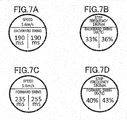
- FIG. 7A to FIG. 7D show display examples in each of which data of a running analysis result is displayed on a display of an external information terminal (e.g. a running watch) .
- FIG. 7A is a display example showing the length of the backward swing period of each leg of a user when the user has run at a running speed of 5.6 m/s
- FIG. 7B is a display example showing a backward swing rate of each leg when the user has run at a step frequency of 180 bps.
- the backward swing rate is a value showing a ratio of the length of the backward swing period to that of the running cycle.
- FIG. 7A is a display example showing the length of the backward swing period of each leg of a user when the user has run at a running speed of 5.6 m/s
- FIG. 7B is a display example showing a backward swing rate of each leg when the user has run at a step frequency of 180 bps.
- the backward swing rate is a value showing a ratio of the
- FIG. 7C is a display example showing the length of the forward swing period of each leg when the user has run at a running speed of 5.6 m/s
- FIG. 7D is a display example showing a forward swing rate of each leg when the user has run at a step frequency of 180 bps.
- the forward swing rate is a value showing a ratio of the length of the forward swing period to that of the running cycle.
- the data of the running analysis result is output to the external information terminal through the communication unit 17 of the main part 1.
- a runner A ran with the running analysis device 100 attached was given a training guidance based on the running analysis result to make the backward swing period short while securing the sufficient forward swing period, and actually went through the training by following the guidance.
- the average length of the backward swing periods was 222 ms
- the average length of the forward swing periods was 262 ms
- the average stride was 190 cm
- the average length of the backward swing periods was 215 ms
- the average length of the forward swing periods was 271 ms
- the average stride was 193 cm.
- the backward swing period(s) decreased and the forward swing period(s) increased, and accordingly the stride (s) at the same step frequency lengthened.
- the running analysis device 100 includes an analyzer (main part 1) that analyzes running of a user using sensor data output from the acceleration sensor 14 attached to the user, and the analyzer includes an indicator identifying unit (CPU 11) that identifies, in a swing phase in a running cycle, a period that serves as an indicator, and analyzes the running of the user on the basis of the period identified by the indicator identifying unit, the period serving as the indicator.
- the analyzer includes an indicator identifying unit (CPU 11) that identifies, in a swing phase in a running cycle, a period that serves as an indicator, and analyzes the running of the user on the basis of the period identified by the indicator identifying unit, the period serving as the indicator.
- the running analysis device 100 identifies, as the period serving as the indicator, a backward swing period in which a leg of the user swings back and a forward swing period in which the leg of the user swings forward, the backward swing period and the forward swing period being included in the swing phase, and analyzes the running on the basis of the backward swing period and the forward swing period. This makes it possible to check whether appropriate training has been done to make the backward swing period, which does not contribute to increase in the running speed, short while securing the sufficient forward swing period, which contributes to increase in the running speed.
- the running analysis device 100 obtains a height position waveform showing a height position of the acceleration sensor 14 by integrating an acceleration signal (s) output from the acceleration sensor 14 twice, takes a timing at which the height position waveform shows a local minimum value as a most sinking timing of the user, and takes, of the swing phase, a period until the most sinking timing as the backward swing period and a period since the most sinking timing as the forward swing period. This makes it possible to identify the backward swing period and the forward swing period with high accuracy, and accordingly can accurately analyze running on the basis of the backward swing period and the forward swing period.
- the graph in FIG. 6 is shown as a running analysis result of a user.
- the graph shows time lengths spent on the stance phase, the backward swing period and the forward swing period of each leg in such a way as to be comparable by running speed.
- the graph is a mere example and hence not a limit. It may be, for example, a graph showing time lengths spent on the stance phase, the backward swing period and the forward swing period of each leg in such a way as to be comparable by step frequency or a graph showing component rates of the running cycle (the stance phase, the backward swing period and the forward swing period) in such a way as to be comparable by running speed or step frequency.
- the time length spent on the forward swing period of each leg is calculated.
- the distance that a user has moved in the forward swing period may be calculated. This is to keep a user from increasing the hang time wastefully by jumping upward (bouncing) in the forward swing period.
- data of a running analysis result is displayed on a display of an external information terminal (e.g. a running watch) .
- an external information terminal e.g. a running watch
- how/where to display the data is not limited thereto.
- data of a running analysis result may be displayed on the display 16 of the main part 1.
- data of accelerations in the respective axes for a predetermined distance that a user has run stored in the storage 15 in advance is analyzed.
- data of accelerations in the respective axes output from the acceleration sensor 14 while a user is running may be analyzed, and data of the analysis result may be displayed on the display 16 so that the user can check the analysis result while running.
- the running analysis device 100 is fixed at the position of the waist of the user, but may be fixed to (at the position of) a leg(s), the head or the like instead of the waist.
- a computer readable medium for the programs of the present invention a flash memory, an EEPROM or the like of the storage 15 is used.
- a portable recording/storage medium such as a CD-ROM
- a carrier wave can also be used.
Abstract
Description
- The present invention relates to a running analysis device, a running analysis method and a running analysis program.
- There has been disclosed a measurement device which can obtain, from output results of an acceleration sensor in the moving direction and the vertical direction when a person walks with the acceleration sensor attached, data relevant to a landing timing(s), a ground leaving timing(s) and a ground contact time(s) during the walk, for example. (Refer to, for example, Japanese Patent Application Publication No.
2012-179114 - However, reducing the ground contact time(s) without changing a stride(s) merely changes a component ratio of the stride and does not directly contribute to increase in the running speed. That is, only reducing the ground contact time is not enough as an indicator for increasing the running speed. The running speed can be increased if a ground contact time rate in a running cycle can be reduced without reducing a stance phase stride of the stride. That is, if a hang time(s) is extended while the step frequency is kept, the ground contact time rate is reduced. Thus, there is a desire for a new evaluation indicator(s) that is effective in stride lengthening.
- The present invention has been conceived in view of the above problems, and objects of the present invention include providing a running analysis device, a running analysis method and a running analysis program each of which can identify an indicator(s) for increasing the running speed.
- According to an aspect of the present invention, there is provided a running analysis device including: an analyzer that analyzes running of a user using sensor data output from a sensor attached to the user, wherein the analyzer includes an indicator identifying unit that identifies, in a swing phase in a running cycle, a period that serves as an indicator.
- The present invention is fully understood from the detailed description given hereinafter and the accompanying drawings, which are given by way of illustration only and thus are not intended to limit the present invention, wherein:
-
FIG. 1 is a diagram showing a state in which a running analysis device according to embodiment(s) of the present invention is attached to a user; -
FIG. 2 is a block diagram showing the functional configuration of a main part of the running analysis device; -
FIG. 3 is a flowchart of a running analysis process; -
FIG. 4 shows a running cycle in a certain period of time; -
FIG. 5 shows most sinking timings (lowest points); -
FIG. 6 shows an example of a running analysis result of a user; -
FIG. 7A is a display example showing the length of a backward swing period of each leg of a user when the user has run at a running speed of 5.6 m/s; -
FIG. 7B is a display example showing a backward swing rate of each leg of the user when the user has run at a step frequency of 180 bps; -
FIG. 7C is a display example showing the length of a forward swing period of each leg of the user when the user has run at a running speed of 5.6 m/s; and -
FIG. 7D is a display example showing a forward swing rate of each leg of the user when the user has run at a step frequency of 180 bps. - Hereinafter, one or more embodiments of the present invention are described in detail with reference to the drawings. However, the present invention is not limited to the illustrated examples.
-
FIG. 1 is a diagram showing a state in which arunning analysis device 100 according to an embodiment (s) of the present invention is attached to a user. - As shown in
FIG. 1 , therunning analysis device 100 includes amain part 1 and abelt part 2. Themain part 1 is fixed at the position of the waist of the user by thebelt part 2. In this application, the right-left direction is X axis, the front-back direction is Y axis, and the up-down direction is Z axis. In X axis, the left direction is positive, and the right direction is negative. In Y axis, the direction opposite to the moving (running) direction is positive, and the moving direction is negative. In Z axis, the up direction is positive, and the down direction is negative. - The "running" in this application means running in a broad sense, and hence includes not only short-distance races, long-distance races and so forth at track and field events but also, what is called, jogging and so forth.
-
FIG. 2 is a block diagram showing main components of the main part (analyzer) 1 according to the embodiment, the main components for performing control. - As shown in
FIG. 2 , themain part 1 includes a CPU (Central Processing Unit) 11 as an indicator identifying unit, anoperation unit 12, a RAM (Random Access Memory) 13, anacceleration sensor 14, astorage 15, adisplay 16 and acommunication unit 17. These components of themain part 1 are connected to one another via abus 18. - The
CPU 11 controls the components of themain part 1. TheCPU 11 reads programs specified from among a system program and application programs stored in thestorage 15, opens the read programs on theRAM 13, and performs a variety of processes in cooperation with the opened programs. Further, theCPU 11 stores, in thestorage 15, data of accelerations in the respective axes output from theacceleration sensor 14. - The
operation unit 12 includes a power button (not shown) to turn on and off a power source, a start/stop button (not shown) to start and stop obtaining data, and a display switch button (not shown) to switch displayed contents. On the basis of commands from theoperation unit 12, theCPU 11 controls the components of themain part 1. - The
RAM 13 is a volatile memory and forms a work area where various data and programs are temporarily stored. - The
acceleration sensor 14 detects accelerations in the respective directions of the three axes, which are at right angles to one another. Theacceleration sensor 14 outputs data of the detected accelerations in the respective axes to theCPU 11. - The
storage 15 is a storage which is constituted of a flash memory, an EEPROM (Electrically Erasable Programmable ROM) or the like and in and from which data and programs are writable and readable. Thestorage 15 stores therein arunning analysis program 151 among others. - The
display 16 is constituted of an LCD (Liquid Crystal Display), an EL (Electro Luminescence) display or the like, and performs a variety of display by following display information from theCPU 11. - The
communication unit 17 outputs obtained data to an external information terminal (s) under the control of theCPU 11. Thecommunication unit 17 is, for example, a wired communication unit such as a USB terminal or a communication unit using a near field wireless communication standard such as Bluetooth®. - Next, a running analysis process performed by the
running analysis device 100 is described with reference toFIG. 3 . - The running analysis process is described in a case where data of accelerations in the respective axes for a predetermined distance that a user has run is obtained in advance and stored in the
storage 15. For example, when the start/stop button is operated to start obtaining data, a user starts and then finishes running a predetermined distance, and when the start/stop button is operated again to stop obtaining data, theCPU 11 performs the running analysis process in cooperation with therunning analysis program 151, which theCPU 11 appropriately reads from thestorage 15 and opens on theRAM 13. - As shown in
FIG. 3 , when theCPU 11 starts the running analysis process, theCPU 11 identifies landing (ground contacting) timings and leaving (ground leaving) timings on the basis of the data of the accelerations in the respective axes (Step S1). The landing timings and the leaving timings can be identified by using a well-known art, and therefore detailed description thereof is omitted here. - Next, the
CPU 11 identifies stance phases and swing phases of the right leg and the left leg on the basis of the landing timings and the leaving timings identified in Step S1 (Step S2) . More specifically, as shown inFIG. 4 , theCPU 11 identifies a period from "0" to "113" points, namely, a period from when the left foot contacts the ground to when the left foot leaves the ground as a stance phase (a stance phase of the left leg), and identifies a period from "113" to "400" points, namely, a period from when the left foot leaves the ground to when the left foot contacts the ground again, as a swing phase (a swing phase of the left leg) . Similarly, theCPU 11 identifies a period from "199" to "321" points, namely, a period from when the right foot contacts the ground to when the right foot leaves the ground, as a stance phase (a stance phase of the right leg), and identifies a period from "0" to "199" points and from "321" to "400" points, namely, a period from when the right foot leaves the ground to when the right foot contacts the ground again, as a swing phase (a swing phase of the right leg) .FIG. 4 shows data from when the left foot contacts the ground to when the left foot contacts the ground again in a certain period of time only, but in reality, in Step S2, theCPU 11 identifies stance phases and swing phases over the whole time that the user has run the predetermined distance. InFIG. 4 , time for two steps from when the left foot contacts the ground to when the left foot contacts the ground again (running cycle) is expressed by normalized time (0 to 400 points). - Next, the
CPU 11 identifies, in the stance phase of each leg identified in Step S2, a timing at which the waist of the user, namely, theacceleration sensor 14, sinks most (Step S3) . More specifically, theCPU 11 obtains a height position waveform T (shown inFIG. 5 ) showing the height position of theacceleration sensor 14 by integrating an acceleration signal (s) in Z axis twice, and then identifies a local minimum value of the height position waveform T in the stance phase of each leg as a most sinking timing (lowest point). - Next, by taking the most sinking timing (lowest point) of each leg identified in Step S3 as a reference, the
CPU 11 identifies (separates) a forward swing period and (from) a backward swing period of the leg that is in the swing phase at the identified most sinking timing (Step S4). The backward swing period is a period in the swing phase, the period in which a leg of a user swings back (in the direction opposite to the moving direction of the user), whereas the forward swing period is a period in the swing phase, the period in which the leg of the user swings forward (in the moving direction of the user). - More specifically, as shown in
FIG. 4 , when "239" point is identified as the most sinking timing (lowest point), theCPU 11 identifies "113" to "239" points, namely, a period from when the left foot leaves the ground to when the most sinking timing is reached, as the backward swing period of the left leg, and identifies "239" to "400" points, namely, a period from when the most sinking timing is reached to when the left foot contacts the ground, as the forward swing period of the left leg. - As described above, it is desired to identify the backward swing period and the forward swing period by taking the most sinking timing (lowest point) as a reference. However, the method for identifying the backward swing period and the forward swing period is not limited thereto. For example, the
CPU 11 may identify a maximum kick timing at which kicking power of kicking the ground in the stance phase of each leg identified in Step S2 is the maximum, and identify the backward swing period and the forward swing period by taking the maximum kick timing as a reference. Further, if themain part 1 is provided with a gyro sensor, theCPU 11 may identify an angle of rotation of the waist of the user on the basis of an angular velocity signal(s) output from the gyro sensor, identify a timing at which the angle of rotation of the waist is a predetermined value in the moving direction of the user, and identify the backward swing period and the forward swing period by taking the timing as a reference. - Here, the method for identifying the maximum kick timing is described with reference to the graph shown at the middle stage of
FIG. 4 . This graph is a graph in which the horizontal axis represents time, and, with time of each sampling point as the origin, the resultant vector of an acceleration vector in Z axis (vertical direction) and an acceleration vector in Y axis (horizontal direction) is drawn. That is, the graph shows change in the resultant vector over time, and the length of the line segment, which shows the resultant vector, indicates the magnitude of the acceleration. - First, the
CPU 11 extracts sampling data of a section which is in the stance phase of each leg and in which values of acceleration data in Y axis are minus, namely, in which the user speeds up in the moving direction, and, for each extracted sampling data, adds up the square of the value of the acceleration data in Y axis and the square of the value of the acceleration data in Z axis and obtains the square root, thereby obtaining the magnitude of the acceleration on the YZ plane. Then, theCPU 11 identifies, in this section, time at which the magnitude of the acceleration is the largest (e.g. inFIG. 4 , the timing of "35" point where 49.7 m/s2 is displayed as the acceleration and the timing of "234" point where 38.7 m/s2 is displayed as the acceleration) as the maximum kick timing. - Next, the
CPU 11 analyzes the running of the user using data of the backward swing period and the forward swing period identified in Step S4 (Step S5) and ends the running analysis process. -
FIG. 6 is a graph showing an example of a running analysis result of a user. -
FIG. 6 shows time lengths spent on the stance phase, the backward swing period and the forward swing period of each leg in such a way as to be comparable by running speed. The time lengths spent on the stance phase, the backward swing period and the forward swing period of each leg are shown to check whether appropriate training has been done to make the backward swing period, which does not contribute to increase in the running speed, short while securing the sufficient forward swing period. If the forward swing period (s) is not long enough, the foot (feet) contacts the ground soon, and hence a hang time stride(s) does not lengthen, and also an action to return the leg(s) becomes insufficient, and hence heel contact tends to occur and accordingly braking at the time of contacting the ground becomes large. On the other hand, if the forward swing period(s) is relatively long (a forward swing rate is high), it directly contributes to stride lengthening, and also the action to return the leg becomes sufficient, and hence the foot can contact the ground near the center of gravity of the body and accordingly braking at the time of contacting the ground becomes relatively small, so that it brings increase in the running speed. -
FIG. 7A to FIG. 7D show display examples in each of which data of a running analysis result is displayed on a display of an external information terminal (e.g. a running watch) . More specifically,FIG. 7A is a display example showing the length of the backward swing period of each leg of a user when the user has run at a running speed of 5.6 m/s, andFIG. 7B is a display example showing a backward swing rate of each leg when the user has run at a step frequency of 180 bps. The backward swing rate is a value showing a ratio of the length of the backward swing period to that of the running cycle.FIG. 7C is a display example showing the length of the forward swing period of each leg when the user has run at a running speed of 5.6 m/s, andFIG. 7D is a display example showing a forward swing rate of each leg when the user has run at a step frequency of 180 bps. The forward swing rate is a value showing a ratio of the length of the forward swing period to that of the running cycle. - The data of the running analysis result is output to the external information terminal through the
communication unit 17 of themain part 1. - Next, a result of training performed on the basis of an analysis result by the running
analysis device 100 of the embodiment is described. - More specifically, a runner A ran with the running
analysis device 100 attached, was given a training guidance based on the running analysis result to make the backward swing period short while securing the sufficient forward swing period, and actually went through the training by following the guidance. - As a result of that, although originally (before the training), at a step frequency of 190 bps, the average length of the backward swing periods was 222 ms, the average length of the forward swing periods was 262 ms, and the average stride was 190 cm, after the training, at the same step frequency (a step frequency of 190 bps), the average length of the backward swing periods was 215 ms, the average length of the forward swing periods was 271 ms, and the average stride was 193 cm.
- That is, as compared with before the training, the backward swing period(s) decreased and the forward swing period(s) increased, and accordingly the stride (s) at the same step frequency lengthened.
- As described above, according to the embodiment, the running
analysis device 100 includes an analyzer (main part 1) that analyzes running of a user using sensor data output from theacceleration sensor 14 attached to the user, and the analyzer includes an indicator identifying unit (CPU 11) that identifies, in a swing phase in a running cycle, a period that serves as an indicator, and analyzes the running of the user on the basis of the period identified by the indicator identifying unit, the period serving as the indicator. - This makes it possible to evaluate the indicator, which is for increasing the running speed, and accordingly can efficiently increase the running speed.
- Further, the running
analysis device 100 identifies, as the period serving as the indicator, a backward swing period in which a leg of the user swings back and a forward swing period in which the leg of the user swings forward, the backward swing period and the forward swing period being included in the swing phase, and analyzes the running on the basis of the backward swing period and the forward swing period. This makes it possible to check whether appropriate training has been done to make the backward swing period, which does not contribute to increase in the running speed, short while securing the sufficient forward swing period, which contributes to increase in the running speed. - Further, the running
analysis device 100 obtains a height position waveform showing a height position of theacceleration sensor 14 by integrating an acceleration signal (s) output from theacceleration sensor 14 twice, takes a timing at which the height position waveform shows a local minimum value as a most sinking timing of the user, and takes, of the swing phase, a period until the most sinking timing as the backward swing period and a period since the most sinking timing as the forward swing period. This makes it possible to identify the backward swing period and the forward swing period with high accuracy, and accordingly can accurately analyze running on the basis of the backward swing period and the forward swing period. - In the above, one or more embodiments of the present invention are described. Needless to say, however, the present invention is not limited thereto and can be appropriately modified in a variety of aspects without departing from the spirit of the present invention.
- In the above embodiment (s), the graph in
FIG. 6 is shown as a running analysis result of a user. The graph shows time lengths spent on the stance phase, the backward swing period and the forward swing period of each leg in such a way as to be comparable by running speed. However, the graph is a mere example and hence not a limit. It may be, for example, a graph showing time lengths spent on the stance phase, the backward swing period and the forward swing period of each leg in such a way as to be comparable by step frequency or a graph showing component rates of the running cycle (the stance phase, the backward swing period and the forward swing period) in such a way as to be comparable by running speed or step frequency. - Further, in the above embodiment(s), in order to derive a running analysis result of a user, the time length spent on the forward swing period of each leg is calculated. Alternatively or additionally, the distance that a user has moved in the forward swing period may be calculated. This is to keep a user from increasing the hang time wastefully by jumping upward (bouncing) in the forward swing period.
- Further, in the above embodiment(s), data of a running analysis result is displayed on a display of an external information terminal (e.g. a running watch) . However, how/where to display the data is not limited thereto. For example, data of a running analysis result may be displayed on the
display 16 of themain part 1. - Further, in the above embodiment(s), data of accelerations in the respective axes for a predetermined distance that a user has run stored in the
storage 15 in advance is analyzed. Additionally or alternatively, data of accelerations in the respective axes output from theacceleration sensor 14 while a user is running may be analyzed, and data of the analysis result may be displayed on thedisplay 16 so that the user can check the analysis result while running. - Further, in the above embodiment (s), the running
analysis device 100 is fixed at the position of the waist of the user, but may be fixed to (at the position of) a leg(s), the head or the like instead of the waist. - Further, in the above embodiment(s), as a computer readable medium for the programs of the present invention, a flash memory, an EEPROM or the like of the
storage 15 is used. However, this is not a limit. As the computer readable medium, a portable recording/storage medium, such as a CD-ROM, can also be used. Further, as a medium to provide data of the programs of the present invention, a carrier wave can also be used. - In the above, one or more embodiments of the present invention are described. However, the scope of the present invention is not limited thereto and includes the scope of claims below and the scope of their equivalents.
Claims (10)
- A running analysis device comprising:an analyzer that analyzes running of a user using sensor data output from a sensor attached to the user, whereinthe analyzer includes an indicator identifying unit that identifies, in a swing phase in a running cycle, a period that serves as an indicator.
- The running analysis device according to claim 1, wherein the indicator identifying unit identifies, as the period serving as the indicator, at least one of (i) a backward swing period in which a leg of the user swings back and (ii) a forward swing period in which the leg of the user swings forward, the backward swing period and the forward swing period being included in the swing phase.
- The running analysis device according to claim 2, wherein
the sensor includes an acceleration sensor that outputs at least an acceleration signal in a vertical direction as the sensor data, and
the indicator identifying unit obtains a height position waveform showing a height position of the acceleration sensor by integrating the acceleration signal twice, takes a timing at which the height position waveform shows a local minimum value as a most sinking timing of the user, and takes, of the swing phase, a period until the most sinking timing as the backward swing period and a period since the most sinking timing as the forward swing period. - The running analysis device according to claim 2, wherein
the sensor includes an acceleration sensor that outputs at least an acceleration signal in a front-back direction and an acceleration signal in a vertical direction as the sensor data, and
the indicator identifying unit extracts the sensor data of a section in which the user speeds up in a moving direction, takes a timing at which a sum of a square of a value of an acceleration in the front-back direction and a square of a value of an acceleration in the vertical direction is largest in the section as a maximum kick timing, and takes, of the swing phase, a period until the maximum kick timing as the backward swing period and a period since the maximum kick timing as the forward swing period. - The running analysis device according to claim 2, wherein
the sensor includes a gyro sensor, and
the indicator identifying unit calculates an angle of rotation of a waist of the user based on an angular velocity signal output from the gyro sensor, identifies a timing at which the angle of rotation of the waist is a predetermined value in a moving direction of the user, and takes, of the swing phase, a period until the timing as the backward swing period and a period since the timing as the forward swing period. - The running analysis device according to claim 1 or 2, wherein
the indicator identifying unit separates the period identified in the swing phase in the running cycle, the period serving as the indicator, and
the analyzer analyzes the running of the user based on the separated period serving as the indicator. - The running analysis device according to any one of claims 1 to 6, wherein the analyzer analyzes the running of the user based on the period identified by the indicator identifying unit, the period serving as the indicator.
- The running analysis device according to any one of claims 1 to 7, further comprising a display that displays an analysis result of the running of the user analyzed by the analyzer.
- A running analysis method comprising:performing a process by which running of a user is analyzed using sensor data output from a sensor attached to the user, whereinthe process includes identifying, in a swing phase in a running cycle, a period that serves as an indicator.
- A running analysis program that causes a computer to function as:an analyzer that analyzes running of a user using sensor data output from a sensor attached to the user, whereinthe analyzer includes an indicator identifying unit that identifies, in a swing phase in a running cycle, a period that serves as an indicator.
Applications Claiming Priority (1)
| Application Number | Priority Date | Filing Date | Title |
|---|---|---|---|
| JP2016231159A JP6508174B2 (en) | 2016-11-29 | 2016-11-29 | Running analysis device, running analysis method and running analysis program |
Publications (2)
| Publication Number | Publication Date |
|---|---|
| EP3327725A1 true EP3327725A1 (en) | 2018-05-30 |
| EP3327725B1 EP3327725B1 (en) | 2021-01-06 |
Family
ID=59997144
Family Applications (1)
| Application Number | Title | Priority Date | Filing Date |
|---|---|---|---|
| EP17193464.9A Active EP3327725B1 (en) | 2016-11-29 | 2017-09-27 | Running analysis device, running analysis method and running analysis program |
Country Status (4)
| Country | Link |
|---|---|
| US (1) | US10596415B2 (en) |
| EP (1) | EP3327725B1 (en) |
| JP (1) | JP6508174B2 (en) |
| CN (1) | CN108114455B (en) |
Cited By (1)
| Publication number | Priority date | Publication date | Assignee | Title |
|---|---|---|---|---|
| CN112274904A (en) * | 2020-12-30 | 2021-01-29 | 南京理工大学 | Pearl ball referee auxiliary penalty system and method based on deep learning |
Families Citing this family (3)
| Publication number | Priority date | Publication date | Assignee | Title |
|---|---|---|---|---|
| JP6919670B2 (en) * | 2019-03-25 | 2021-08-18 | カシオ計算機株式会社 | Running analysis device, running analysis method and running analysis program |
| CN110180158B (en) * | 2019-07-02 | 2021-04-23 | 乐跑体育互联网(武汉)有限公司 | Running state identification method and system and terminal equipment |
| CN111310601A (en) * | 2020-01-20 | 2020-06-19 | 北京正和恒基滨水生态环境治理股份有限公司 | Intelligent runway system based on face recognition, speed measuring method and electronic equipment |
Citations (6)
| Publication number | Priority date | Publication date | Assignee | Title |
|---|---|---|---|---|
| WO2012109244A1 (en) * | 2011-02-07 | 2012-08-16 | New Balance Athletic Shoe, Inc. | Systems and methods for monitoring athletic performance |
| JP2012179114A (en) | 2011-02-28 | 2012-09-20 | Hiroshima Univ | Measurement device, measurement method and measurement program |
| US20120253234A1 (en) * | 2009-09-03 | 2012-10-04 | Ming Young Biomedical Corp. | System and method for analyzing gait using fabric sensors |
| US20130178958A1 (en) * | 2012-01-09 | 2013-07-11 | Garmin Switzerland Gmbh | Method and system for determining user performance characteristics |
| US20150081245A1 (en) * | 2013-09-19 | 2015-03-19 | Casio Computer Co., Ltd. | Exercise support device, exercise support method, and exercise support program |
| US20160029954A1 (en) * | 2014-07-31 | 2016-02-04 | Seiko Epson Corporation | Exercise analysis apparatus, exercise analysis system, exercise analysis method, and exercise analysis program |
Family Cites Families (9)
| Publication number | Priority date | Publication date | Assignee | Title |
|---|---|---|---|---|
| US7970568B1 (en) * | 2005-04-05 | 2011-06-28 | Schabowski John V | Pedometer method and apparatus |
| US20100204615A1 (en) * | 2006-01-20 | 2010-08-12 | 6Th Dimension Devices Inc. | Method and system for assessing athletic performance |
| JP5504810B2 (en) * | 2009-10-06 | 2014-05-28 | オムロンヘルスケア株式会社 | Walking posture determination device, control program, and control method |
| WO2014089238A1 (en) * | 2012-12-04 | 2014-06-12 | Mapmyfitness, Inc. | Gait analysis system and method |
| JP5811360B2 (en) * | 2012-12-27 | 2015-11-11 | カシオ計算機株式会社 | Exercise information display system, exercise information display method, and exercise information display program |
| JP2016034482A (en) | 2014-07-31 | 2016-03-17 | セイコーエプソン株式会社 | Exercise analysis device, exercise analysis method, exercise analysis program, and exercise analysis system |
| CN105387871A (en) * | 2014-08-26 | 2016-03-09 | 精工爱普生株式会社 | Motion analysis device, motion analysis method and motion analysis system |
| JP2016043260A (en) | 2014-08-26 | 2016-04-04 | セイコーエプソン株式会社 | Motion analysis device, motion analysis method, and motion analysis system |
| US10115319B2 (en) * | 2015-03-26 | 2018-10-30 | President And Fellows Of Harvard College | Systems and methods for detecting overstriding in runners |
-
2016
- 2016-11-29 JP JP2016231159A patent/JP6508174B2/en active Active
-
2017
- 2017-09-27 EP EP17193464.9A patent/EP3327725B1/en active Active
- 2017-09-28 US US15/719,488 patent/US10596415B2/en active Active
- 2017-10-12 CN CN201710951052.0A patent/CN108114455B/en active Active
Patent Citations (6)
| Publication number | Priority date | Publication date | Assignee | Title |
|---|---|---|---|---|
| US20120253234A1 (en) * | 2009-09-03 | 2012-10-04 | Ming Young Biomedical Corp. | System and method for analyzing gait using fabric sensors |
| WO2012109244A1 (en) * | 2011-02-07 | 2012-08-16 | New Balance Athletic Shoe, Inc. | Systems and methods for monitoring athletic performance |
| JP2012179114A (en) | 2011-02-28 | 2012-09-20 | Hiroshima Univ | Measurement device, measurement method and measurement program |
| US20130178958A1 (en) * | 2012-01-09 | 2013-07-11 | Garmin Switzerland Gmbh | Method and system for determining user performance characteristics |
| US20150081245A1 (en) * | 2013-09-19 | 2015-03-19 | Casio Computer Co., Ltd. | Exercise support device, exercise support method, and exercise support program |
| US20160029954A1 (en) * | 2014-07-31 | 2016-02-04 | Seiko Epson Corporation | Exercise analysis apparatus, exercise analysis system, exercise analysis method, and exercise analysis program |
Cited By (1)
| Publication number | Priority date | Publication date | Assignee | Title |
|---|---|---|---|---|
| CN112274904A (en) * | 2020-12-30 | 2021-01-29 | 南京理工大学 | Pearl ball referee auxiliary penalty system and method based on deep learning |
Also Published As
| Publication number | Publication date |
|---|---|
| US10596415B2 (en) | 2020-03-24 |
| US20180147446A1 (en) | 2018-05-31 |
| JP2018086136A (en) | 2018-06-07 |
| EP3327725B1 (en) | 2021-01-06 |
| CN108114455B (en) | 2020-06-12 |
| JP6508174B2 (en) | 2019-05-08 |
| CN108114455A (en) | 2018-06-05 |
Similar Documents
| Publication | Publication Date | Title |
|---|---|---|
| US10596415B2 (en) | Running analysis device | |
| JP6131706B2 (en) | Walking posture meter and program | |
| US10667726B2 (en) | Gait posture meter and program | |
| US10694980B2 (en) | Exercise support device, exercise support method and exercise support program | |
| EP3124982A1 (en) | Correlation coefficient correction method, motion analysis method, correlation coefficient correction device, and program | |
| US10504381B2 (en) | On-running landing position evaluation method, on-running landing position evaluation apparatus, detection method, detection apparatus, running motion evaluation method, and running motion evaluation apparatus | |
| JP2012008637A (en) | Pedometer and program | |
| JP2015062654A (en) | Gait estimation device, program thereof, stumble risk calculation device and program thereof | |
| KR101718392B1 (en) | Mobile terminal for computing foot length information using foot-mounted inertia motion unit, and method using the same | |
| WO2014181605A1 (en) | Walking posture meter and program | |
| JP6711433B2 (en) | Running analysis device, running analysis method and running analysis program | |
| JP6233123B2 (en) | Sensor device, sampling method and program | |
| US20220005575A1 (en) | Information processing device, information processing method, and non-transitory recording medium | |
| JP2020022596A (en) | Motor function evaluation device, motor function evaluation system, motor function evaluation program, and motor function evaluation method | |
| EP3950074A1 (en) | Running method determination device, running-method determination method, and program | |
| JP2017012586A (en) | Swing data arithmetic device, swing data arithmetic system, swing data arithmetic method, and program | |
| JP2017169837A (en) | Measuring device, measuring method, and measuring program | |
| JPWO2016063661A1 (en) | Information processing apparatus, information processing method, and program | |
| JP2018054617A (en) | Sampling frequency control device, sampling frequency control method, and program | |
| US20160325138A1 (en) | Swing analyzing device, swing analyzing method, storage medium, and swing analyzing system | |
| JP2015071000A (en) | Exercise analysis program | |
| US11481947B2 (en) | Information processing device estimating a parameter based on acquired indexes representing an exercise state of a subject, information processing method, and non-transitory recording medium | |
| JPWO2014020718A1 (en) | Walking style discrimination system, walking style discrimination device, and walking style discrimination method | |
| JP2019101191A (en) | Travel data evaluation system, information processing system, and information processing server | |
| CN115282589A (en) | Somatosensory game method based on rope skipping action |
Legal Events
| Date | Code | Title | Description |
|---|---|---|---|
| PUAI | Public reference made under article 153(3) epc to a published international application that has entered the european phase |
Free format text: ORIGINAL CODE: 0009012 |
|
| STAA | Information on the status of an ep patent application or granted ep patent |
Free format text: STATUS: REQUEST FOR EXAMINATION WAS MADE |
|
| 17P | Request for examination filed |
Effective date: 20170927 |
|
| AK | Designated contracting states |
Kind code of ref document: A1 Designated state(s): AL AT BE BG CH CY CZ DE DK EE ES FI FR GB GR HR HU IE IS IT LI LT LU LV MC MK MT NL NO PL PT RO RS SE SI SK SM TR |
|
| AX | Request for extension of the european patent |
Extension state: BA ME |
|
| RBV | Designated contracting states (corrected) |
Designated state(s): AL AT BE BG CH CY CZ DE DK EE ES FI FR GB GR HR HU IE IS IT LI LT LU LV MC MK MT NL NO PL PT RO RS SE SI SK SM TR |
|
| STAA | Information on the status of an ep patent application or granted ep patent |
Free format text: STATUS: EXAMINATION IS IN PROGRESS |
|
| 17Q | First examination report despatched |
Effective date: 20191127 |
|
| RIC1 | Information provided on ipc code assigned before grant |
Ipc: A63B 24/00 20060101ALN20200722BHEP Ipc: G06K 9/00 20060101ALI20200722BHEP Ipc: G16H 40/63 20180101ALI20200722BHEP Ipc: A61B 5/11 20060101ALI20200722BHEP Ipc: G16H 20/30 20180101AFI20200722BHEP |
|
| RIC1 | Information provided on ipc code assigned before grant |
Ipc: G16H 40/63 20180101ALI20200729BHEP Ipc: G16H 20/30 20180101AFI20200729BHEP Ipc: G06K 9/00 20060101ALI20200729BHEP Ipc: A61B 5/11 20060101ALI20200729BHEP Ipc: A63B 24/00 20060101ALN20200729BHEP |
|
| GRAP | Despatch of communication of intention to grant a patent |
Free format text: ORIGINAL CODE: EPIDOSNIGR1 |
|
| STAA | Information on the status of an ep patent application or granted ep patent |
Free format text: STATUS: GRANT OF PATENT IS INTENDED |
|
| INTG | Intention to grant announced |
Effective date: 20200904 |
|
| GRAS | Grant fee paid |
Free format text: ORIGINAL CODE: EPIDOSNIGR3 |
|
| GRAA | (expected) grant |
Free format text: ORIGINAL CODE: 0009210 |
|
| STAA | Information on the status of an ep patent application or granted ep patent |
Free format text: STATUS: THE PATENT HAS BEEN GRANTED |
|
| AK | Designated contracting states |
Kind code of ref document: B1 Designated state(s): AL AT BE BG CH CY CZ DE DK EE ES FI FR GB GR HR HU IE IS IT LI LT LU LV MC MK MT NL NO PL PT RO RS SE SI SK SM TR |
|
| REG | Reference to a national code |
Ref country code: GB Ref legal event code: FG4D |
|
| REG | Reference to a national code |
Ref country code: AT Ref legal event code: REF Ref document number: 1353230 Country of ref document: AT Kind code of ref document: T Effective date: 20210115 Ref country code: CH Ref legal event code: EP |
|
| REG | Reference to a national code |
Ref country code: DE Ref legal event code: R096 Ref document number: 602017030814 Country of ref document: DE |
|
| REG | Reference to a national code |
Ref country code: IE Ref legal event code: FG4D |
|
| REG | Reference to a national code |
Ref country code: NL Ref legal event code: MP Effective date: 20210106 |
|
| REG | Reference to a national code |
Ref country code: AT Ref legal event code: MK05 Ref document number: 1353230 Country of ref document: AT Kind code of ref document: T Effective date: 20210106 |
|
| REG | Reference to a national code |
Ref country code: LT Ref legal event code: MG9D |
|
| PG25 | Lapsed in a contracting state [announced via postgrant information from national office to epo] |
Ref country code: FI Free format text: LAPSE BECAUSE OF FAILURE TO SUBMIT A TRANSLATION OF THE DESCRIPTION OR TO PAY THE FEE WITHIN THE PRESCRIBED TIME-LIMIT Effective date: 20210106 Ref country code: HR Free format text: LAPSE BECAUSE OF FAILURE TO SUBMIT A TRANSLATION OF THE DESCRIPTION OR TO PAY THE FEE WITHIN THE PRESCRIBED TIME-LIMIT Effective date: 20210106 Ref country code: GR Free format text: LAPSE BECAUSE OF FAILURE TO SUBMIT A TRANSLATION OF THE DESCRIPTION OR TO PAY THE FEE WITHIN THE PRESCRIBED TIME-LIMIT Effective date: 20210407 Ref country code: PT Free format text: LAPSE BECAUSE OF FAILURE TO SUBMIT A TRANSLATION OF THE DESCRIPTION OR TO PAY THE FEE WITHIN THE PRESCRIBED TIME-LIMIT Effective date: 20210506 Ref country code: NO Free format text: LAPSE BECAUSE OF FAILURE TO SUBMIT A TRANSLATION OF THE DESCRIPTION OR TO PAY THE FEE WITHIN THE PRESCRIBED TIME-LIMIT Effective date: 20210406 Ref country code: LT Free format text: LAPSE BECAUSE OF FAILURE TO SUBMIT A TRANSLATION OF THE DESCRIPTION OR TO PAY THE FEE WITHIN THE PRESCRIBED TIME-LIMIT Effective date: 20210106 Ref country code: BG Free format text: LAPSE BECAUSE OF FAILURE TO SUBMIT A TRANSLATION OF THE DESCRIPTION OR TO PAY THE FEE WITHIN THE PRESCRIBED TIME-LIMIT Effective date: 20210406 |
|
| PG25 | Lapsed in a contracting state [announced via postgrant information from national office to epo] |
Ref country code: RS Free format text: LAPSE BECAUSE OF FAILURE TO SUBMIT A TRANSLATION OF THE DESCRIPTION OR TO PAY THE FEE WITHIN THE PRESCRIBED TIME-LIMIT Effective date: 20210106 Ref country code: LV Free format text: LAPSE BECAUSE OF FAILURE TO SUBMIT A TRANSLATION OF THE DESCRIPTION OR TO PAY THE FEE WITHIN THE PRESCRIBED TIME-LIMIT Effective date: 20210106 Ref country code: PL Free format text: LAPSE BECAUSE OF FAILURE TO SUBMIT A TRANSLATION OF THE DESCRIPTION OR TO PAY THE FEE WITHIN THE PRESCRIBED TIME-LIMIT Effective date: 20210106 Ref country code: AT Free format text: LAPSE BECAUSE OF FAILURE TO SUBMIT A TRANSLATION OF THE DESCRIPTION OR TO PAY THE FEE WITHIN THE PRESCRIBED TIME-LIMIT Effective date: 20210106 Ref country code: SE Free format text: LAPSE BECAUSE OF FAILURE TO SUBMIT A TRANSLATION OF THE DESCRIPTION OR TO PAY THE FEE WITHIN THE PRESCRIBED TIME-LIMIT Effective date: 20210106 |
|
| PG25 | Lapsed in a contracting state [announced via postgrant information from national office to epo] |
Ref country code: IS Free format text: LAPSE BECAUSE OF FAILURE TO SUBMIT A TRANSLATION OF THE DESCRIPTION OR TO PAY THE FEE WITHIN THE PRESCRIBED TIME-LIMIT Effective date: 20210506 |
|
| REG | Reference to a national code |
Ref country code: DE Ref legal event code: R097 Ref document number: 602017030814 Country of ref document: DE |
|
| PG25 | Lapsed in a contracting state [announced via postgrant information from national office to epo] |
Ref country code: EE Free format text: LAPSE BECAUSE OF FAILURE TO SUBMIT A TRANSLATION OF THE DESCRIPTION OR TO PAY THE FEE WITHIN THE PRESCRIBED TIME-LIMIT Effective date: 20210106 Ref country code: CZ Free format text: LAPSE BECAUSE OF FAILURE TO SUBMIT A TRANSLATION OF THE DESCRIPTION OR TO PAY THE FEE WITHIN THE PRESCRIBED TIME-LIMIT Effective date: 20210106 Ref country code: SM Free format text: LAPSE BECAUSE OF FAILURE TO SUBMIT A TRANSLATION OF THE DESCRIPTION OR TO PAY THE FEE WITHIN THE PRESCRIBED TIME-LIMIT Effective date: 20210106 |
|
| PLBE | No opposition filed within time limit |
Free format text: ORIGINAL CODE: 0009261 |
|
| STAA | Information on the status of an ep patent application or granted ep patent |
Free format text: STATUS: NO OPPOSITION FILED WITHIN TIME LIMIT |
|
| PG25 | Lapsed in a contracting state [announced via postgrant information from national office to epo] |
Ref country code: DK Free format text: LAPSE BECAUSE OF FAILURE TO SUBMIT A TRANSLATION OF THE DESCRIPTION OR TO PAY THE FEE WITHIN THE PRESCRIBED TIME-LIMIT Effective date: 20210106 Ref country code: RO Free format text: LAPSE BECAUSE OF FAILURE TO SUBMIT A TRANSLATION OF THE DESCRIPTION OR TO PAY THE FEE WITHIN THE PRESCRIBED TIME-LIMIT Effective date: 20210106 Ref country code: SK Free format text: LAPSE BECAUSE OF FAILURE TO SUBMIT A TRANSLATION OF THE DESCRIPTION OR TO PAY THE FEE WITHIN THE PRESCRIBED TIME-LIMIT Effective date: 20210106 |
|
| 26N | No opposition filed |
Effective date: 20211007 |
|
| PG25 | Lapsed in a contracting state [announced via postgrant information from national office to epo] |
Ref country code: AL Free format text: LAPSE BECAUSE OF FAILURE TO SUBMIT A TRANSLATION OF THE DESCRIPTION OR TO PAY THE FEE WITHIN THE PRESCRIBED TIME-LIMIT Effective date: 20210106 Ref country code: ES Free format text: LAPSE BECAUSE OF FAILURE TO SUBMIT A TRANSLATION OF THE DESCRIPTION OR TO PAY THE FEE WITHIN THE PRESCRIBED TIME-LIMIT Effective date: 20210106 |
|
| PG25 | Lapsed in a contracting state [announced via postgrant information from national office to epo] |
Ref country code: SI Free format text: LAPSE BECAUSE OF FAILURE TO SUBMIT A TRANSLATION OF THE DESCRIPTION OR TO PAY THE FEE WITHIN THE PRESCRIBED TIME-LIMIT Effective date: 20210106 |
|
| PG25 | Lapsed in a contracting state [announced via postgrant information from national office to epo] |
Ref country code: IT Free format text: LAPSE BECAUSE OF FAILURE TO SUBMIT A TRANSLATION OF THE DESCRIPTION OR TO PAY THE FEE WITHIN THE PRESCRIBED TIME-LIMIT Effective date: 20210106 |
|
| REG | Reference to a national code |
Ref country code: CH Ref legal event code: PL |
|
| REG | Reference to a national code |
Ref country code: BE Ref legal event code: MM Effective date: 20210930 |
|
| PG25 | Lapsed in a contracting state [announced via postgrant information from national office to epo] |
Ref country code: IS Free format text: LAPSE BECAUSE OF FAILURE TO SUBMIT A TRANSLATION OF THE DESCRIPTION OR TO PAY THE FEE WITHIN THE PRESCRIBED TIME-LIMIT Effective date: 20210506 Ref country code: MC Free format text: LAPSE BECAUSE OF FAILURE TO SUBMIT A TRANSLATION OF THE DESCRIPTION OR TO PAY THE FEE WITHIN THE PRESCRIBED TIME-LIMIT Effective date: 20210106 |
|
| PG25 | Lapsed in a contracting state [announced via postgrant information from national office to epo] |
Ref country code: LU Free format text: LAPSE BECAUSE OF NON-PAYMENT OF DUE FEES Effective date: 20210927 Ref country code: IE Free format text: LAPSE BECAUSE OF NON-PAYMENT OF DUE FEES Effective date: 20210927 Ref country code: BE Free format text: LAPSE BECAUSE OF NON-PAYMENT OF DUE FEES Effective date: 20210930 |
|
| PG25 | Lapsed in a contracting state [announced via postgrant information from national office to epo] |
Ref country code: LI Free format text: LAPSE BECAUSE OF NON-PAYMENT OF DUE FEES Effective date: 20210930 Ref country code: CH Free format text: LAPSE BECAUSE OF NON-PAYMENT OF DUE FEES Effective date: 20210930 |
|
| PG25 | Lapsed in a contracting state [announced via postgrant information from national office to epo] |
Ref country code: HU Free format text: LAPSE BECAUSE OF FAILURE TO SUBMIT A TRANSLATION OF THE DESCRIPTION OR TO PAY THE FEE WITHIN THE PRESCRIBED TIME-LIMIT; INVALID AB INITIO Effective date: 20170927 |
|
| PG25 | Lapsed in a contracting state [announced via postgrant information from national office to epo] |
Ref country code: NL Free format text: LAPSE BECAUSE OF NON-PAYMENT OF DUE FEES Effective date: 20210206 Ref country code: CY Free format text: LAPSE BECAUSE OF FAILURE TO SUBMIT A TRANSLATION OF THE DESCRIPTION OR TO PAY THE FEE WITHIN THE PRESCRIBED TIME-LIMIT Effective date: 20210106 |
|
| PGFP | Annual fee paid to national office [announced via postgrant information from national office to epo] |
Ref country code: GB Payment date: 20230803 Year of fee payment: 7 |
|
| PGFP | Annual fee paid to national office [announced via postgrant information from national office to epo] |
Ref country code: FR Payment date: 20230808 Year of fee payment: 7 Ref country code: DE Payment date: 20230802 Year of fee payment: 7 |