EP3327469A1 - Mobile scanning inspection system - Google Patents
Mobile scanning inspection system Download PDFInfo
- Publication number
- EP3327469A1 EP3327469A1 EP17199447.8A EP17199447A EP3327469A1 EP 3327469 A1 EP3327469 A1 EP 3327469A1 EP 17199447 A EP17199447 A EP 17199447A EP 3327469 A1 EP3327469 A1 EP 3327469A1
- Authority
- EP
- European Patent Office
- Prior art keywords
- inspection
- inspection device
- plane
- laser
- region
- Prior art date
- Legal status (The legal status is an assumption and is not a legal conclusion. Google has not performed a legal analysis and makes no representation as to the accuracy of the status listed.)
- Granted
Links
Images




Classifications
-
- G—PHYSICS
- G01—MEASURING; TESTING
- G01V—GEOPHYSICS; GRAVITATIONAL MEASUREMENTS; DETECTING MASSES OR OBJECTS; TAGS
- G01V8/00—Prospecting or detecting by optical means
- G01V8/10—Detecting, e.g. by using light barriers
- G01V8/20—Detecting, e.g. by using light barriers using multiple transmitters or receivers
- G01V8/26—Detecting, e.g. by using light barriers using multiple transmitters or receivers using mechanical scanning systems
-
- G—PHYSICS
- G01—MEASURING; TESTING
- G01V—GEOPHYSICS; GRAVITATIONAL MEASUREMENTS; DETECTING MASSES OR OBJECTS; TAGS
- G01V5/00—Prospecting or detecting by the use of ionising radiation, e.g. of natural or induced radioactivity
- G01V5/20—Detecting prohibited goods, e.g. weapons, explosives, hazardous substances, contraband or smuggled objects
- G01V5/22—Active interrogation, i.e. by irradiating objects or goods using external radiation sources, e.g. using gamma rays or cosmic rays
-
- G—PHYSICS
- G01—MEASURING; TESTING
- G01V—GEOPHYSICS; GRAVITATIONAL MEASUREMENTS; DETECTING MASSES OR OBJECTS; TAGS
- G01V8/00—Prospecting or detecting by optical means
- G01V8/10—Detecting, e.g. by using light barriers
- G01V8/20—Detecting, e.g. by using light barriers using multiple transmitters or receivers
Definitions
- the present application relates to the field of scanning inspection technology, and in particular to a mobile scanning inspection system.
- Mobile scanning inspection system such as vehicle-mounted container inspection system
- the mobile scanning inspection system has a collapsible L-shaped inspection arm that includes a horizontal cross arm and a vertical upright arm.
- the inspection arm is unfolded to form an inspection tunnel, and the object to be inspected such as a container is placed in the inspection tunnel, and the inspection device is placed on the inspection arm so that the object is scanned and inspected when the vehicle body moves.
- the existing mobile scanning inspection system uses a bumper bar connected to a travel switch to carry out the collision protection for the vehicle body and the inspection arm.
- the bumper bar When the bumper bar is blocked by the object to be inspected, it causes the travel switch to be actuated, thereby stopping the scanner vehicle to prevent the vehicle body or the inspection arm from hitting the object to be inspected.
- the anti-collision bumper type of protection scheme only has a protective effect on the object to be inspected that has a height exceeding the height of the bumper and a regular shape.
- more and more customs began to use mobile scanning inspection system to inspect objects with irregular contours such as aviation containers, air trays and others.
- Anti-collision bumper type of single point protection has been unable to meet the needs of such applications.
- the present application provides a mobile scanning inspection system capable of plane protection on both sides of the inspection tunnel, thereby providing a more comprehensive collision protection and reducing the risk of the vehicle body and the inspection arm being hit.
- a mobile scanning inspection system comprising a vehicle body and an inspection arm including a cross arm and a vertical arm, a first inspection device and a second inspection device are provided on the cross arm; the first inspection device is arranged on the side proximate the vehicle body and a first laser inspection plane emitted from the first inspection device during use is arranged parallel to the side plane of the vehicle body and the length of the longest portion of the first laser inspection plane is longer than the length of the vehicle body; the second inspection device is provided on the side proximate the vertical arm, and a second laser inspection plane emitted from the second inspection device during use is arranged parallel to the side plane of the vehicle body and the second laser inspection plane is centered on the vertical arm, and extends a first preset distance and a second preset distance forward and backward.
- the system further comprises: a controller coupled to the first inspection device and the second inspection device; in the scanning inspection process, an object to be inspected is placed between the first laser inspection plane and the second laser inspection plane; the first inspection device and/or the second inspection device issues an alarm signal when the first inspection device and/or the second inspection device inspects an object exceeding a preset size; the controller is configured to stop the movement of the vehicle body when the alarm signal from the first inspection device and/or the second inspection device is received.
- the first laser inspection plane is divided into a plurality of inspection regions including a first inspection region, a second inspection region and a third inspection region adjacent to each other, wherein the first inspection region is closest to the rear end of the vehicle body;
- the alarm signal comprises a first alarm signal, a second alarm signal and a third alarm signal; when the first inspection device inspects the object in the first inspection region, the first alarm signal is issued to indicate that a collision will occur in each of the plurality of inspection regions; when the first inspection device inspects the object in the second inspection region, the second alarm signal is issued to indicate that a collision will occur in each of the plurality of inspection regions other than the first inspection region; and when the first inspection device inspects the object in the third inspection region, the third alarm signal is issued to indicate that a collision will occur in each of the plurality of inspection regions other than the first inspection region and the second inspection region.
- the first laser inspection plane is divided into a first inspection region and a second inspection region adjacent to each other, wherein the first inspection region is closest to the rear of the vehicle body;
- the alarm signal comprises a first alarm signal and a second alarm signal; when the first inspection device inspects the object in the first inspection region, the first alarm signal is issued to indicate that a collision will occur in the first inspection region and the second inspection region; and when the first inspection device inspects the object in the second inspection region, the second alarm signal is issued to indicate that a collision will occur in the second inspection region.
- the coverage area of the first laser inspection plane and the coverage area of the second laser inspection plane can be adjusted according to user settings.
- the first inspection device and the second inspection device are connected to an electronic equipment network and receive the user settings transmitted by the electronic equipment.
- the first inspection device and the second inspection device are both regional laser scanners.
- the controller is a PLC.
- the first preset distance is equal to the second preset distance and both are 1 meter.
- the longest portion of the first laser inspection plane extends a third preset distance before the front end of the vehicle body and a fourth preset distance after the rear end of the vehicle body, respectively.
- the system further comprises: an inspection arm support and a third inspection device; the third inspection device is provided on the inspection arm support with a preset height from the bottom plane of an inspection tunnel formed by the cross arm and the vertical arm; the third laser inspection plane emitted from the third inspection device is arranged parallel to the bottom plane of the inspection tunnel; wherein the preset height is set in accordance with the height of the object to be inspected.
- the third inspection device is a regional laser scanner coupled to the controller; when the third inspection device inspects an object exceeding the preset height, a signal is output to the controller to instruct the controller to issue an alarm.
- the point protection in the prior art is extended to plane protection, which greatly reduces the probability of collision between the mobile scanning inspection system and the scanned object.
- the coverage of the laser inspection plane is very wide, it is possible for the user to determine, at the stage when the object to be inspected is being positioned before the start of the scanning, whether or not a collision is liable to occur, thereby effectively avoiding the risk by prompting.
- the zonal anti-collision method can directly indicate or show which inspection region is subject to collision, so as to facilitate the subsequent analysis and processing of the operator.
- FIG.1 is a schematic diagram of a mobile scanning inspection system shown in accordance with an example embodiment.
- the mobile scanning inspection system 10 may be, for example, a vehicle-mounted scanning inspection system including a vehicle body 102, an inspection arm 104, and an inspection arm support 106.
- the inspection arm 104 includes a cross arm 1042 and a vertical arm 1044.
- the inspection arm support 106 is used to support the inspection arm 104.
- the inspection arm 104 When the scanning is performed, the inspection arm 104 is expanded in an L-shape to form an inspection tunnel in which the object to be inspected O, such as a container, is placed, and the inspection device (not shown) may be placed on the inspection arm 104 so that the object to be inspected O is scanning inspected by the inspection device when the vehicle body 102 moves.
- the mobile scanning inspection system 10 can also check a moving vehicle, in which case the vehicle body 102 remains stationary, and the moving vehicle moves through the inspection tunnel formed by the inspection arm 104 to be subjected to the scanning of the inspection device.
- the inspection arm 104 When the scanning is completed, the inspection arm 104 is retracted on the top of the vehicle body 102 so that the mobile scanning inspection system 10 can travel like a normal vehicle.
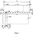
- FIG.2 is a top view of the mobile scanning inspection system shown in FIG.1 .
- FIG.3 is a side view of the mobile scanning inspection system shown in FIG.1 .
- a first inspection device 108 and a second inspection device 110 are provided on the cross arm 1042, respectively.
- the first inspection device 108 is arranged on the side proximate the vehicle body 102 and a first laser inspection plane S1 (as shown by a dotted line on the side in the vicinity of the vehicle body 102 in FIG.2 ) emitted from the first inspection device 108 is parallel to the side plane of the vehicle body 102 and the length L1 of the longest portion of the first laser inspection plane S1 is longer than the length L3 of the vehicle body 102.
- the longest portion of the first laser inspection plane S1 extends a preset distance La beyond the front end 1022 of the vehicle body 102 and a preset distance Lb beyond the rear end 1024 of the vehicle body 102, respectively.
- La and Lb are, for example, 1 meter, since the length L3 of the vehicle body 102 is usually about 10 meters, the length L1 of the longest portion of the first laser inspection plane S1 is about 12 meters. It should be noted that this value is only an example, rather than limiting the application. In practical applications, the values of the lengths can be set according to actual needs.
- the first laser inspection plane S1 will be higher than the front end 1022 and the rear end 1024.
- the second inspection device 110 is provided on the side proximate the vertical arm 1044 (not shown in FIG.2 ) and a second laser inspection plane S2 emitted from the second inspection device 110 is parallel to the side plane of the vehicle body 102 and the second laser inspection plane S2 is centered around the vertical arm 1044, and extends a preset distance Lc and a preset distance Ld forward and backward.
- the second laser inspection plane S2 may be used to protect the vertical arm 1044.
- Lc and Ld both equal, for example, 1 meter, in addition to the normal width of the vertical arm which is 1.2 m, thus the second laser inspection plane S2 has a protection length of about 3.2 m. It should be noted that this value is only an example, rather than limiting the present application, in practical application, the lengths can be set according to actual needs.
- the first inspection device 108 and the second inspection device 110 may be regional laser scanners, such as a regional laser scanner of the type TiM351 provided by SICK, Germany.
- the regional laser scanners replace the existing bumper bar, which are mounted on both sides of the cross arm 1042.
- the regional laser scanners emit a laser fan parallel to the side of the vehicle body 102 in a way of circular scanning to inspect a preset size object that is encountered during the movement of the vehicle body 102 so that the vehicle body 102, the inspection arm 104, and the inspection arm support 106 is plane-protected.
- the first inspection device 108 and the second inspection device 110 may be other sensors having a laser scanning function, and the present application is not limited in this regard.
- the coverage area of the first laser inspection plane S1 and the second laser inspection plane S2 may be adjusted according to user settings.
- the first inspection device 108 and the second inspection device 110 may be connected to an electronic equipment (e.g., a debug computer, a server, etc.) via a network, such as via an Ethernet connection, to receive user setting instructions sent by the electronic equipment so that the user can adjust the sizes of the coverage areas of the first laser inspection plane S1 and the second laser inspection plane S2 by the setting interface provided by the electronic equipment.
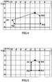
- FIG.4 is a schematic diagram of the adjustment interface of the first laser inspection plane coverage area shown in an example.
- FIG.5 is a schematic diagram of the adjustment interface of the second laser inspection plane coverage area shown in an example.
- the coverage areas of the first laser inspection plane S1 and the second laser inspection plane S2 can be determined by adjusting the four input points IN1 to IN4 in the figure, respectively.
- a plurality of sets of the drawn coverage area of the first laser inspection plane S1 or the second laser inspection plane S2 can be simultaneously recorded in each of the regional laser scanners.
- FIG.6 is an interconnection diagram of a first inspection device and a second inspection device according to an example.
- the first inspection device 108 and the second inspection device 110 are connected to the electronic equipment 20 via the network to receive a coverage area of the first laser inspection plane S1 and the second laser inspection plane S2 set by the user through the electronic equipment.
- the first inspection device 108 and the second inspection device 110 are also connected to the controller 112 of the mobile scanning inspection system 10.
- the controller 112 may be, for example, a PLC (Programmable Logic Controller), or may be a single chip or the like.
- the above-described coverage area is selected, for example, four input points IN1 to IN4 of the regional laser scanner can be controlled by the four output points of the PLC connected to the first inspection device 108 and the second inspection device 110 to select which group of protection area is enabled.
- the object to be inspected O is placed in the inspection tunnel formed by the first laser inspection plane S1 and the second laser inspection plane S2.
- the first inspection device 108 and/or the second inspection device 110 may issue an alarm signal to the controller 112 when the first inspection device 108 and/or the second inspection device 110 detect a preset size of an object.
- the controller 112 receives the alarm signal from the first inspection device 108 and/or the second inspection device 110, the controller 112 immediately controls the vehicle body 102 to stop moving, so as to prevent collisions.
- FIG.7 is a schematic diagram showing the partition of the first laser inspection plane.
- the first laser inspection plane S1 may be divided into a plurality of inspection regions.
- the regional laser scanner has four output signals, one of which is status output of the sensor itself, so that the signal outputted from the remaining three output signals can be used as an alarm signal to alert the controller 112.
- the first laser inspection plane S1 is divided into three inspection regions: a first inspection region A1, a second inspection region A2, and a third inspection region A3, wherein the first inspection region A1 is the inspection region closest to the rear end 1024. It should be noted that the division of the inspection region in the figure is merely an example, and not a limitation of the present application.
- the first inspection device 108 inspects an object of a preset size in the first inspection region A1, all of the first inspection region A1, the second inspection region A2 and the third inspection region A3 are simultaneously triggered, and the first inspection device 108 outputs a signal 000 indicating that a collision will occur in all the first inspection region A1, the second inspection region A2, and the third inspection region A3.
- both of the second inspection region A2 and the third inspection region A3 are simultaneously triggered, and the first inspection device 108 outputs a signal 100 indicating that a collision will occur in both the second inspection region A2 and the third inspection region A3.
- the first inspection device 108 inspects an object of a preset size in the third inspection region A3, only the third inspection region A3 is triggered, and the first inspection device 108 outputs a signal 110 indicating that a collision will occur in the third inspection region A3.
- the zonal collision prevention scheme can visually indicate or show in which inspection region collision may occur, and thus facilitates the operator's subsequent analysis and processing.
- the first laser inspection plane S1 may also be divided into two inspection regions (not shown): a first inspection region and a second inspection region, wherein the first inspection region is the inspection region closest to the rear end.
- a first alarm signal is issued to indicate that a collision will occur in both the first inspection region and the second inspection region;
- a second alarm signal is issued to indicate that a collision will occur in the second inspection region.
- the first laser inspection plane S1 may be divided into more than three inspection regions (not shown) when the first inspection device 108 may provide more than three alarm signals.
- the plurality of inspection regions may include other inspection regions in addition to the first inspection region, the second inspection region and the third inspection region. Among them, the first inspection region is the inspection region closest to the rear end.
- a first alarm signal is issued to indicate that a collision will occur in all of the plurality of inspection regions
- a second alarm signal is issued to indicate that a collision will occur in all of the plurality of inspection regions except for the first inspection region
- a third alarm signal is issued to indicate that all of the plurality of inspection regions except the first inspection region and the second inspection region collision; and so on.
- the mobile scanning inspection system of the present application extends the point protection in the prior art to planar protection, which greatly reduces the probability of collision between the mobile scanning inspection system and the scanned object. And because the coverage of the laser inspection plane is very wide, it is possible for the user to determine, at the stage in which the object to be inspected is positioned before the start of the scanning, whether or not a collision is likely to occur thereby effectively avoiding the risk by prompting.
- the zonal anti-collision method can directly indicate or show which inspection region has collided, so as to facilitate the subsequent analysis and processing of the operator.
- FIG.8 is a schematic diagram of another mobile scanning inspection system according to another embodiment.
- the mobile scanning inspection system 30 shown in FIG.8 further includes: a third inspection device 302.
- the third inspection device 302 is placed on the inspection arm support 106 at a preset distance D from the bottom plane Sb of the inspection tunnel, where the object to be inspected O can be either a vehicle or a container to be scanned or the like.
- the preset distance D may be set according to actual needs, for example, according to the highest height of the object to be inspected O that may be passed, thereby providing height-exceeding protection to the inspection arm support 106.
- the third laser inspection plane S3 emitted from the third inspection device 302 is parallel to the bottom plane Sb of the inspection tunnel.
- the third inspection device 302 outputs a signal to the connected controller 112 so that the controller 112 controls the mobile scanning inspection system 20 to issue an alarm information for exceeding of the height limit, thus warning the driver of the vehicle being scanned that the vehicle exceeds the height limit, and is prohibited from entering the inspection tunnel.
- the third inspection device 302 may also be a regional laser scanner.
- the mobile scanning inspection system of embodiment of the present application further provides a height-exceeding anti-collision protection scheme for the height of the boom, which can effectively avoid the entry of the scanned vehicle with over-limit height.
Landscapes
- Physics & Mathematics (AREA)
- Life Sciences & Earth Sciences (AREA)
- General Life Sciences & Earth Sciences (AREA)
- General Physics & Mathematics (AREA)
- Geophysics (AREA)
- High Energy & Nuclear Physics (AREA)
- Traffic Control Systems (AREA)
- Length Measuring Devices By Optical Means (AREA)
- Optical Radar Systems And Details Thereof (AREA)
Abstract
Description
- The present application relates to the field of scanning inspection technology, and in particular to a mobile scanning inspection system.
- Mobile scanning inspection system, such as vehicle-mounted container inspection system, can be used for scanning inspection of containers, etc., applicable to customs, anti-terrorism and other national security areas, with advantages of flexible maneuver, equipment integration, advanced operation and so on. Typically, the mobile scanning inspection system has a collapsible L-shaped inspection arm that includes a horizontal cross arm and a vertical upright arm. When the scanning is performed, the inspection arm is unfolded to form an inspection tunnel, and the object to be inspected such as a container is placed in the inspection tunnel, and the inspection device is placed on the inspection arm so that the object is scanned and inspected when the vehicle body moves.
- At the time of inspection, in order to prevent the object to be inspected such as a container or the like from being hit on the vehicle body or the inspection arm, the existing mobile scanning inspection system uses a bumper bar connected to a travel switch to carry out the collision protection for the vehicle body and the inspection arm. During the movement of the vehicle body, when the bumper bar is blocked by the object to be inspected, it causes the travel switch to be actuated, thereby stopping the scanner vehicle to prevent the vehicle body or the inspection arm from hitting the object to be inspected.
- However, the anti-collision bumper type of protection scheme only has a protective effect on the object to be inspected that has a height exceeding the height of the bumper and a regular shape. In recent years, more and more customs began to use mobile scanning inspection system to inspect objects with irregular contours such as aviation containers, air trays and others. Anti-collision bumper type of single point protection has been unable to meet the needs of such applications.
- The above-described information disclosed in the background section is for the purpose of enhancing the understanding of the background of the present application and therefore may include information that does not constitute prior art known to those skilled in the art.
- In view of this, the present application provides a mobile scanning inspection system capable of plane protection on both sides of the inspection tunnel, thereby providing a more comprehensive collision protection and reducing the risk of the vehicle body and the inspection arm being hit.
- Other features and advantages of the present application will be apparent from the following detailed description, or in part, by the practice of the application.
- According to an aspect of the present application, there is provided a mobile scanning inspection system comprising a vehicle body and an inspection arm including a cross arm and a vertical arm, a first inspection device and a second inspection device are provided on the cross arm; the first inspection device is arranged on the side proximate the vehicle body and a first laser inspection plane emitted from the first inspection device during use is arranged parallel to the side plane of the vehicle body and the length of the longest portion of the first laser inspection plane is longer than the length of the vehicle body; the second inspection device is provided on the side proximate the vertical arm, and a second laser inspection plane emitted from the second inspection device during use is arranged parallel to the side plane of the vehicle body and the second laser inspection plane is centered on the vertical arm, and extends a first preset distance and a second preset distance forward and backward.
- According to an embodiment of the present application, the system further comprises: a controller coupled to the first inspection device and the second inspection device; in the scanning inspection process, an object to be inspected is placed between the first laser inspection plane and the second laser inspection plane; the first inspection device and/or the second inspection device issues an alarm signal when the first inspection device and/or the second inspection device inspects an object exceeding a preset size; the controller is configured to stop the movement of the vehicle body when the alarm signal from the first inspection device and/or the second inspection device is received.
- According to an embodiment of the present application, the first laser inspection plane is divided into a plurality of inspection regions including a first inspection region, a second inspection region and a third inspection region adjacent to each other, wherein the first inspection region is closest to the rear end of the vehicle body; the alarm signal comprises a first alarm signal, a second alarm signal and a third alarm signal; when the first inspection device inspects the object in the first inspection region, the first alarm signal is issued to indicate that a collision will occur in each of the plurality of inspection regions; when the first inspection device inspects the object in the second inspection region, the second alarm signal is issued to indicate that a collision will occur in each of the plurality of inspection regions other than the first inspection region; and when the first inspection device inspects the object in the third inspection region, the third alarm signal is issued to indicate that a collision will occur in each of the plurality of inspection regions other than the first inspection region and the second inspection region.
- According to an embodiment of the present application, the first laser inspection plane is divided into a first inspection region and a second inspection region adjacent to each other, wherein the first inspection region is closest to the rear of the vehicle body; the alarm signal comprises a first alarm signal and a second alarm signal; when the first inspection device inspects the object in the first inspection region, the first alarm signal is issued to indicate that a collision will occur in the first inspection region and the second inspection region; and when the first inspection device inspects the object in the second inspection region, the second alarm signal is issued to indicate that a collision will occur in the second inspection region.
- According to an embodiment of the present application, the coverage area of the first laser inspection plane and the coverage area of the second laser inspection plane can be adjusted according to user settings.
- According to an embodiment of the present application, the first inspection device and the second inspection device are connected to an electronic equipment network and receive the user settings transmitted by the electronic equipment.
- According to an embodiment of the present application, the first inspection device and the second inspection device are both regional laser scanners.
- According to an embodiment of the present application, the controller is a PLC.
- According to an embodiment of the present application, the first preset distance is equal to the second preset distance and both are 1 meter.
- According to an embodiment of the present application, the longest portion of the first laser inspection plane extends a third preset distance before the front end of the vehicle body and a fourth preset distance after the rear end of the vehicle body, respectively.
- According to an embodiment of the present application, the system further comprises: an inspection arm support and a third inspection device; the third inspection device is provided on the inspection arm support with a preset height from the bottom plane of an inspection tunnel formed by the cross arm and the vertical arm; the third laser inspection plane emitted from the third inspection device is arranged parallel to the bottom plane of the inspection tunnel; wherein the preset height is set in accordance with the height of the object to be inspected.
- According to an embodiment of the present application, the third inspection device is a regional laser scanner coupled to the controller; when the third inspection device inspects an object exceeding the preset height, a signal is output to the controller to instruct the controller to issue an alarm.
- According to the mobile scanning inspection system of the present application, the point protection in the prior art is extended to plane protection, which greatly reduces the probability of collision between the mobile scanning inspection system and the scanned object. And because the coverage of the laser inspection plane is very wide, it is possible for the user to determine, at the stage when the object to be inspected is being positioned before the start of the scanning, whether or not a collision is liable to occur, thereby effectively avoiding the risk by prompting. In addition, the zonal anti-collision method can directly indicate or show which inspection region is subject to collision, so as to facilitate the subsequent analysis and processing of the operator.
- It is to be understood that the foregoing general description and the following detailed description are exemplary only and do not limit the present application.
- The foregoing and other objects, features and advantages of the present application will become more apparent from the following detailed description of certain embodiments thereof, given by way of illustration not limitation, with reference to the accompanying drawings.
-
Figure 1 is a schematic diagram of a mobile scanning inspection system shown in accordance with an example embodiment. -
Figure 2 is a top view of the mobile scanning inspection system shown inFIG.1 . -
Figure 3 is a side view of the mobile scanning inspection system shown inFIG.1 . -
Figure 4 is a schematic diagram of the adjustment interface of the first laser inspection plane coverage area shown in an example. -
Figure 5 is a schematic diagram of the adjustment interface of the second laser inspection plane coverage area shown in an example. -
Figure 6 is an interconnection diagram of a first inspection device and a second inspection device according to an example. -
Figure 7 is a schematic diagram of the partitions of the first laser inspection plane. -
Figure 8 is a schematic diagram of another mobile scanning inspection system according to another embodiment. - Illustrative embodiments will now be described more fully with reference to the accompanying drawings. However, the embodiments may be implemented in many forms and should not be construed as limited to the examples set forth herein; rather, these embodiments are provided so that the present application will be more full and complete, and the teachings of the embodiments will be conveyed comprehensively to those skilled in the art. The drawings are merely illustrative of the present application and are not necessarily to scale. The same reference numerals in the drawings denote the same or similar parts, and thus repeated description thereof will be omitted.
- In addition, the features, structures, or characteristics described may be combined in one or more embodiments in any suitable manner. In the following description, numerous specific details are set forth to give a full understanding of the embodiments of the present application. However, those skilled in the art will appreciate that one or more of the particular details may be omitted by practicing the technical solution of the present application, or other methods, components, devices, steps, and the like may be employed. In other instances, well-known structures, methods, devices, implementations, or operations are not shown or described in detail to avoid distracting thus obscuring aspects of the present application.
-
FIG.1 is a schematic diagram of a mobile scanning inspection system shown in accordance with an example embodiment. As shown inFIG.1 , the mobilescanning inspection system 10 may be, for example, a vehicle-mounted scanning inspection system including avehicle body 102, aninspection arm 104, and aninspection arm support 106. Wherein theinspection arm 104 includes across arm 1042 and avertical arm 1044. Theinspection arm support 106 is used to support theinspection arm 104. When the scanning is performed, theinspection arm 104 is expanded in an L-shape to form an inspection tunnel in which the object to be inspected O, such as a container, is placed, and the inspection device (not shown) may be placed on theinspection arm 104 so that the object to be inspected O is scanning inspected by the inspection device when thevehicle body 102 moves. In addition, the mobilescanning inspection system 10 can also check a moving vehicle, in which case thevehicle body 102 remains stationary, and the moving vehicle moves through the inspection tunnel formed by theinspection arm 104 to be subjected to the scanning of the inspection device. When the scanning is completed, theinspection arm 104 is retracted on the top of thevehicle body 102 so that the mobilescanning inspection system 10 can travel like a normal vehicle. -
FIG.2 is a top view of the mobile scanning inspection system shown inFIG.1 .FIG.3 is a side view of the mobile scanning inspection system shown inFIG.1 . As shown inFIG.2 andFIG.3 , afirst inspection device 108 and asecond inspection device 110 are provided on thecross arm 1042, respectively. Thefirst inspection device 108 is arranged on the side proximate thevehicle body 102 and a first laser inspection plane S1 (as shown by a dotted line on the side in the vicinity of thevehicle body 102 inFIG.2 ) emitted from thefirst inspection device 108 is parallel to the side plane of thevehicle body 102 and the length L1 of the longest portion of the first laser inspection plane S1 is longer than the length L3 of thevehicle body 102. In some embodiments, for example, the longest portion of the first laser inspection plane S1 extends a preset distance La beyond thefront end 1022 of thevehicle body 102 and a preset distance Lb beyond therear end 1024 of thevehicle body 102, respectively. In some embodiments, La and Lb are, for example, 1 meter, since the length L3 of thevehicle body 102 is usually about 10 meters, the length L1 of the longest portion of the first laser inspection plane S1 is about 12 meters. It should be noted that this value is only an example, rather than limiting the application. In practical applications, the values of the lengths can be set according to actual needs. In addition, in order to comprehensively protect thevehicle body 102, the first laser inspection plane S1 will be higher than thefront end 1022 and therear end 1024. - With reference to
FIG.2 , thesecond inspection device 110 is provided on the side proximate the vertical arm 1044 (not shown inFIG.2 ) and a second laser inspection plane S2 emitted from thesecond inspection device 110 is parallel to the side plane of thevehicle body 102 and the second laser inspection plane S2 is centered around thevertical arm 1044, and extends a preset distance Lc and a preset distance Ld forward and backward. The second laser inspection plane S2 may be used to protect thevertical arm 1044. In some embodiments, Lc and Ld both equal, for example, 1 meter, in addition to the normal width of the vertical arm which is 1.2 m, thus the second laser inspection plane S2 has a protection length of about 3.2 m. It should be noted that this value is only an example, rather than limiting the present application, in practical application, the lengths can be set according to actual needs. - In some embodiments, the
first inspection device 108 and thesecond inspection device 110 may be regional laser scanners, such as a regional laser scanner of the type TiM351 provided by SICK, Germany. The regional laser scanners replace the existing bumper bar, which are mounted on both sides of thecross arm 1042. The regional laser scanners emit a laser fan parallel to the side of thevehicle body 102 in a way of circular scanning to inspect a preset size object that is encountered during the movement of thevehicle body 102 so that thevehicle body 102, theinspection arm 104, and theinspection arm support 106 is plane-protected. In addition, thefirst inspection device 108 and thesecond inspection device 110 may be other sensors having a laser scanning function, and the present application is not limited in this regard. - The coverage area of the first laser inspection plane S1 and the second laser inspection plane S2 may be adjusted according to user settings. For example, the
first inspection device 108 and thesecond inspection device 110 may be connected to an electronic equipment (e.g., a debug computer, a server, etc.) via a network, such as via an Ethernet connection, to receive user setting instructions sent by the electronic equipment so that the user can adjust the sizes of the coverage areas of the first laser inspection plane S1 and the second laser inspection plane S2 by the setting interface provided by the electronic equipment.FIG.4 is a schematic diagram of the adjustment interface of the first laser inspection plane coverage area shown in an example.FIG.5 is a schematic diagram of the adjustment interface of the second laser inspection plane coverage area shown in an example. As shown inFIG.4 and FIG.5 , the coverage areas of the first laser inspection plane S1 and the second laser inspection plane S2 can be determined by adjusting the four input points IN1 to IN4 in the figure, respectively. A plurality of sets of the drawn coverage area of the first laser inspection plane S1 or the second laser inspection plane S2 can be simultaneously recorded in each of the regional laser scanners. -
FIG.6 is an interconnection diagram of a first inspection device and a second inspection device according to an example. As shown inFIG.6 , thefirst inspection device 108 and thesecond inspection device 110 are connected to theelectronic equipment 20 via the network to receive a coverage area of the first laser inspection plane S1 and the second laser inspection plane S2 set by the user through the electronic equipment. In addition, thefirst inspection device 108 and thesecond inspection device 110 are also connected to thecontroller 112 of the mobilescanning inspection system 10. Thecontroller 112 may be, for example, a PLC (Programmable Logic Controller), or may be a single chip or the like. When the above-described coverage area is selected, for example, four input points IN1 to IN4 of the regional laser scanner can be controlled by the four output points of the PLC connected to thefirst inspection device 108 and thesecond inspection device 110 to select which group of protection area is enabled. - In the scanning inspection process, as shown in
FIG.2 , the object to be inspected O is placed in the inspection tunnel formed by the first laser inspection plane S1 and the second laser inspection plane S2. Thefirst inspection device 108 and/or thesecond inspection device 110 may issue an alarm signal to thecontroller 112 when thefirst inspection device 108 and/or thesecond inspection device 110 detect a preset size of an object. When thecontroller 112 receives the alarm signal from thefirst inspection device 108 and/or thesecond inspection device 110, thecontroller 112 immediately controls thevehicle body 102 to stop moving, so as to prevent collisions. - In addition, the mobile
scanning inspection system 10 of the present application may provide a zonal collision prevention scheme.FIG.7 is a schematic diagram showing the partition of the first laser inspection plane. As shown inFIG.7 , the first laser inspection plane S1 may be divided into a plurality of inspection regions. Taking the case where thefirst inspection device 108 is a regional laser scanner as an example, the regional laser scanner has four output signals, one of which is status output of the sensor itself, so that the signal outputted from the remaining three output signals can be used as an alarm signal to alert thecontroller 112. In this example, the first laser inspection plane S1 is divided into three inspection regions: a first inspection region A1, a second inspection region A2, and a third inspection region A3, wherein the first inspection region A1 is the inspection region closest to therear end 1024. It should be noted that the division of the inspection region in the figure is merely an example, and not a limitation of the present application. - When the
first inspection device 108 inspects an object of a preset size in the first inspection region A1, all of the first inspection region A1, the second inspection region A2 and the third inspection region A3 are simultaneously triggered, and thefirst inspection device 108 outputs a signal 000 indicating that a collision will occur in all the first inspection region A1, the second inspection region A2, and the third inspection region A3. - When the
first inspection device 108 inspects an object of a preset size in the second inspection region A2, both of the second inspection region A2 and the third inspection region A3 are simultaneously triggered, and thefirst inspection device 108 outputs a signal 100 indicating that a collision will occur in both the second inspection region A2 and the third inspection region A3. - When the
first inspection device 108 inspects an object of a preset size in the third inspection region A3, only the third inspection region A3 is triggered, and thefirst inspection device 108 outputs asignal 110 indicating that a collision will occur in the third inspection region A3. - The zonal collision prevention scheme can visually indicate or show in which inspection region collision may occur, and thus facilitates the operator's subsequent analysis and processing.
- Alternatively, the first laser inspection plane S1 may also be divided into two inspection regions (not shown): a first inspection region and a second inspection region, wherein the first inspection region is the inspection region closest to the rear end. When the
first inspection device 108 inspects an object of a preset size in the first inspection region, a first alarm signal is issued to indicate that a collision will occur in both the first inspection region and the second inspection region; when thefirst inspection device 108 inspects an object of a preset size in the second inspection region, a second alarm signal is issued to indicate that a collision will occur in the second inspection region. - In addition, the first laser inspection plane S1 may be divided into more than three inspection regions (not shown) when the
first inspection device 108 may provide more than three alarm signals. The plurality of inspection regions may include other inspection regions in addition to the first inspection region, the second inspection region and the third inspection region. Among them, the first inspection region is the inspection region closest to the rear end. When thefirst inspection device 108 inspects an object of a preset size in the first inspection region, a first alarm signal is issued to indicate that a collision will occur in all of the plurality of inspection regions; when thefirst inspection device 108 inspects an object of a preset size in the second inspection region, a second alarm signal is issued to indicate that a collision will occur in all of the plurality of inspection regions except for the first inspection region; when thefirst inspection device 108 inspects an object of a preset size in the third inspection region, a third alarm signal is issued to indicate that all of the plurality of inspection regions except the first inspection region and the second inspection region collision; and so on. - The mobile scanning inspection system of the present application extends the point protection in the prior art to planar protection, which greatly reduces the probability of collision between the mobile scanning inspection system and the scanned object. And because the coverage of the laser inspection plane is very wide, it is possible for the user to determine, at the stage in which the object to be inspected is positioned before the start of the scanning, whether or not a collision is likely to occur thereby effectively avoiding the risk by prompting. In addition, the zonal anti-collision method can directly indicate or show which inspection region has collided, so as to facilitate the subsequent analysis and processing of the operator.
-
FIG.8 is a schematic diagram of another mobile scanning inspection system according to another embodiment. The difference from the mobilescanning inspection system 10 shown inFIG.1 is that the mobilescanning inspection system 30 shown inFIG.8 further includes: athird inspection device 302. Thethird inspection device 302 is placed on theinspection arm support 106 at a preset distance D from the bottom plane Sb of the inspection tunnel, where the object to be inspected O can be either a vehicle or a container to be scanned or the like. In practical applications, the preset distance D may be set according to actual needs, for example, according to the highest height of the object to be inspected O that may be passed, thereby providing height-exceeding protection to theinspection arm support 106. - The third laser inspection plane S3 emitted from the
third inspection device 302 is parallel to the bottom plane Sb of the inspection tunnel. When the scanned vehicle exceeding the height limit is scanned through the inspection tunnel by thethird inspection device 302, thethird inspection device 302 outputs a signal to theconnected controller 112 so that thecontroller 112 controls the mobilescanning inspection system 20 to issue an alarm information for exceeding of the height limit, thus warning the driver of the vehicle being scanned that the vehicle exceeds the height limit, and is prohibited from entering the inspection tunnel. - In some embodiments, the
third inspection device 302 may also be a regional laser scanner. - The mobile scanning inspection system of embodiment of the present application further provides a height-exceeding anti-collision protection scheme for the height of the boom, which can effectively avoid the entry of the scanned vehicle with over-limit height.
- Example embodiments of the present application have been particularly shown and described above. It is to be understood that the present application is not limited to the detailed construction, arrangement or implementation described herein; rather, the present application is intended to cover various modifications and equivalent arrangements included within the scope of the appended claims.
Claims (12)
- A mobile scanning inspection system (10), comprising a vehicle body (102) and an inspection arm (104), the inspection arm (104) including a cross arm (1042) and a vertical arm (1044), characterized in that,
a first inspection device (108) and a second inspection device (110) are provided on the cross arm (1042);
the first inspection device (108) is arranged on the side proximate the vehicle body (102), a first laser inspection plane (S1) emitted from the first inspection device (108) being parallel to the side plane of the vehicle body (102), and a length of the longest portion of the first laser inspection plane (S1) being longer than a length of the vehicle body (102); and
the second inspection device (110) is provided on the side proximate the vertical arm (1044), a second laser inspection plane (S2) emitted from the second inspection device (110) being parallel to the side plane of the vehicle body (102), and the second laser inspection plane (S2) being centered on the vertical arm (1044), and extending a first preset distance (Lc) and a second preset distance (Ld) forward and backward. - The system (10) according to claim 1, characterized in that the system (10) further comprises: a controller coupled to the first inspection device (108) and the second inspection device (110); in the scanning inspection process, an object to be inspected (O) is placed between the first laser inspection plane (S1) and the second laser inspection plane (S2); the first inspection device (108) and/or the second inspection device (110) are configured to issue an alarm signal when the first inspection device (108) and/or the second inspection device (110) inspects an object exceeding a preset size; and the controller is configured to stop the movement of the vehicle body (102) when the alarm signal from the first inspection device (108) and/or the second inspection device (110) is received.
- The system (10) according to claim 2, characterized in that the first laser inspection plane (S1) is divided into a plurality of inspection regions, including a first inspection region, a second inspection region and a third inspection region adjacent to each other, wherein the first inspection region is closest to the rear of the vehicle body (102); the alarm signal comprises a first alarm signal, a second alarm signal and a third alarm signal; and the first inspection device is configured: when the first inspection device (108) detects the object in the first inspection region, to issue the first alarm signal to indicate that a collision will occur in each of the plurality of inspection regions, when the first inspection device (108) detects the object in the second inspection region, to issue the second alarm signal to indicate that a collision will occur in each of the plurality of inspection regions other than the first inspection region, and when the first inspection device (108) detects the object in the third inspection region, to issue the third alarm signal to indicate that a collision will occur in each of the plurality of inspection regions other than the first inspection region and the second inspection region.
- The system (10) according to claim 2, characterized in that the first laser inspection plane (S1) is divided into a first inspection region and a second inspection region adjacent to each other, wherein the first inspection region is closest to the rear of the vehicle body (102); the alarm signal comprises a first alarm signal and a second alarm signal; and the first inspection device is configured: when the first inspection device (108) detects the object in the first inspection region, to issue the first alarm signal to indicate that a collision will occur in the first inspection region and the second inspection region; and when the first inspection device (108) detects the object in the second inspection region, to issue the second alarm signal to indicate that a collision will occur in the second inspection region.
- The system (10) according to any one of claims 1-4, characterized in that the coverage area of the first laser inspection plane (S1) and the coverage area of the second laser inspection plane (S2) can be adjusted according to user settings.
- The system (10) according to claim 5, characterized in that the first inspection device (108) and the second inspection device (110) are connected to an electronic equipment network, and receive the user settings transmitted by the electronic equipment.
- The system (10) according to any one of claims 1-4, characterized in that the first inspection device (108) and the second inspection device (110) are both regional laser scanners.
- The system (10) according to any one of claims 2-4, characterized in that the controller is a programmable logic controller.
- The system (10) according to any one of claims 1-4, characterized in that the first preset distance (Lc) is equal to the second preset distance (Ld) and both are 1 meter.
- The system (10) according to any one of claims 1-4, characterized in that the longest portion of the first laser inspection plane (S1) extends a third preset distance (La) before the front end (1022) of the vehicle body (102) and a fourth preset distance (Lb) after the rear end (1024) of the vehicle body (102), respectively.
- The system (10) according to any one of claims 2-4, characterized in that the system (10) further comprises: an inspection arm support (106) and a third inspection device (302); wherein the third inspection device (302) is provided on the inspection arm support (106) with a preset height (D) from the bottom plane (Sb) of an inspection tunnel formed by the cross arm (1042) and the vertical arm (1044); a third laser inspection plane (S3) emitted from the third inspection device (302) is parallel to the bottom plane (Sb) of the inspection tunnel; and wherein the preset height (D) is set in accordance with the height of the object to be inspected (O).
- The system (10) according to claim 11, characterized in that the third inspection device (302) is an regional laser scanner coupled to the controller (112); when the third inspection device (302) inspects an object exceeding the preset height (D), a signal is output to the controller (112) to instruct the controller (112) to issue an alarm.
Priority Applications (1)
| Application Number | Priority Date | Filing Date | Title |
|---|---|---|---|
| PL17199447T PL3327469T3 (en) | 2016-11-25 | 2017-10-31 | Mobile scanning inspection system |
Applications Claiming Priority (1)
| Application Number | Priority Date | Filing Date | Title |
|---|---|---|---|
| CN201611063861.XA CN106483578B (en) | 2016-11-25 | 2016-11-25 | Mobile scanning-detecting system |
Publications (2)
| Publication Number | Publication Date |
|---|---|
| EP3327469A1 true EP3327469A1 (en) | 2018-05-30 |
| EP3327469B1 EP3327469B1 (en) | 2022-01-05 |
Family
ID=58275200
Family Applications (1)
| Application Number | Title | Priority Date | Filing Date |
|---|---|---|---|
| EP17199447.8A Active EP3327469B1 (en) | 2016-11-25 | 2017-10-31 | Mobile scanning inspection system |
Country Status (5)
| Country | Link |
|---|---|
| US (1) | US10690803B2 (en) |
| EP (1) | EP3327469B1 (en) |
| CN (1) | CN106483578B (en) |
| PL (1) | PL3327469T3 (en) |
| WO (1) | WO2018095103A1 (en) |
Families Citing this family (3)
| Publication number | Priority date | Publication date | Assignee | Title |
|---|---|---|---|---|
| CN106483578B (en) * | 2016-11-25 | 2019-03-29 | 同方威视技术股份有限公司 | Mobile scanning-detecting system |
| CN108761555B (en) * | 2018-05-25 | 2024-06-21 | 清华大学 | Container vehicle inspection system and container vehicle inspection method |
| CN118011511A (en) * | 2022-10-28 | 2024-05-10 | 同方威视技术股份有限公司 | Autonomous inspection system with inspection area |
Citations (5)
| Publication number | Priority date | Publication date | Assignee | Title |
|---|---|---|---|---|
| US20110038453A1 (en) * | 2002-07-23 | 2011-02-17 | Edward James Morton | Compact Mobile Cargo Scanning System |
| US20130039462A1 (en) * | 2008-02-28 | 2013-02-14 | Rapican Systems, Inc. | Dual mode x-ray vehicle scanning system |
| US20140226146A1 (en) * | 2013-02-14 | 2014-08-14 | Kapsch Trafficcom Ag | Device for vehicle measuring |
| CN104777520A (en) * | 2015-04-03 | 2015-07-15 | 北京君和信达科技有限公司 | Automatic moving target checking system based on laser scanner |
| CN105445745A (en) * | 2015-12-04 | 2016-03-30 | 同方威视技术股份有限公司 | Mobile target state monitoring method and apparatus, and vehicle rapid inspection system thereof |
Family Cites Families (19)
| Publication number | Priority date | Publication date | Assignee | Title |
|---|---|---|---|---|
| US5128874A (en) * | 1990-01-02 | 1992-07-07 | Honeywell Inc. | Inertial navigation sensor integrated obstacle detection system |
| DE19950060C2 (en) * | 1999-10-16 | 2003-01-16 | Kostal Leopold Gmbh & Co Kg | Optoelectronic sensor device for a motor vehicle |
| EP1106995B1 (en) * | 1999-12-03 | 2004-08-04 | Matsushita Electric Industrial Co., Ltd. | Laser beam inspection apparatus |
| US7486768B2 (en) * | 2002-07-23 | 2009-02-03 | Rapiscan Security Products, Inc. | Self-contained mobile inspection system and method |
| US7369643B2 (en) * | 2002-07-23 | 2008-05-06 | Rapiscan Security Products, Inc. | Single boom cargo scanning system |
| CN200996943Y (en) * | 2006-10-09 | 2007-12-26 | 同方威视技术股份有限公司 | Cargo inspecter |
| CN102147487B (en) * | 2006-10-13 | 2012-09-26 | 同方威视技术股份有限公司 | Mobile vehicle inspection system |
| KR20090034436A (en) * | 2007-10-04 | 2009-04-08 | 광주과학기술원 | Security System Using Laser Range Finder and Intruder Detection Method Using Laser Range Finder |
| CN101183082B (en) * | 2007-12-14 | 2011-08-17 | 清华大学 | Ship radiation image-forming detecting system |
| CN102336366A (en) * | 2010-07-26 | 2012-02-01 | 上海派恩科技有限公司 | Monitoring method for anticollision of quayside container crane sling |
| CN203284078U (en) * | 2013-05-08 | 2013-11-13 | 北京国泰星云科技有限公司 | Container collision prevention automatic control system for RTG/RMG lifting appliance in container wharf |
| CN103879741B (en) * | 2014-04-04 | 2015-02-18 | 上海东源计算机自动化工程有限公司 | Laser anti-collision early warning system used for bulk cargo stockyard |
| CN105197801A (en) * | 2014-06-12 | 2015-12-30 | 上海海镭激光科技有限公司 | Walking positioning, deviation correcting and collision preventing method for tire crane |
| CN204086172U (en) * | 2014-09-02 | 2015-01-07 | 清华大学 | Vehicular check system |
| US9847022B2 (en) * | 2015-07-22 | 2017-12-19 | Ace/Avant Concrete Construction Co., Inc. | Vehicle detection system and method |
| JP5950015B2 (en) * | 2015-11-16 | 2016-07-13 | 富士電機株式会社 | Radiation monitor |
| CN105522988B (en) * | 2015-12-29 | 2018-01-30 | 同方威视技术股份有限公司 | Vehicle guidance system, the method for vehicle directional and safety check vehicle |
| CN206353210U (en) * | 2016-11-25 | 2017-07-25 | 同方威视技术股份有限公司 | Portable scanning-detecting system |
| CN106483578B (en) * | 2016-11-25 | 2019-03-29 | 同方威视技术股份有限公司 | Mobile scanning-detecting system |
-
2016
- 2016-11-25 CN CN201611063861.XA patent/CN106483578B/en active Active
-
2017
- 2017-08-31 WO PCT/CN2017/099944 patent/WO2018095103A1/en not_active Ceased
- 2017-10-31 EP EP17199447.8A patent/EP3327469B1/en active Active
- 2017-10-31 PL PL17199447T patent/PL3327469T3/en unknown
- 2017-10-31 US US15/798,569 patent/US10690803B2/en active Active
Patent Citations (5)
| Publication number | Priority date | Publication date | Assignee | Title |
|---|---|---|---|---|
| US20110038453A1 (en) * | 2002-07-23 | 2011-02-17 | Edward James Morton | Compact Mobile Cargo Scanning System |
| US20130039462A1 (en) * | 2008-02-28 | 2013-02-14 | Rapican Systems, Inc. | Dual mode x-ray vehicle scanning system |
| US20140226146A1 (en) * | 2013-02-14 | 2014-08-14 | Kapsch Trafficcom Ag | Device for vehicle measuring |
| CN104777520A (en) * | 2015-04-03 | 2015-07-15 | 北京君和信达科技有限公司 | Automatic moving target checking system based on laser scanner |
| CN105445745A (en) * | 2015-12-04 | 2016-03-30 | 同方威视技术股份有限公司 | Mobile target state monitoring method and apparatus, and vehicle rapid inspection system thereof |
Also Published As
| Publication number | Publication date |
|---|---|
| CN106483578A (en) | 2017-03-08 |
| EP3327469B1 (en) | 2022-01-05 |
| US20180149769A1 (en) | 2018-05-31 |
| US10690803B2 (en) | 2020-06-23 |
| PL3327469T3 (en) | 2022-05-02 |
| CN106483578B (en) | 2019-03-29 |
| WO2018095103A1 (en) | 2018-05-31 |
Similar Documents
| Publication | Publication Date | Title |
|---|---|---|
| US8922431B2 (en) | Apparatus, a system and a method for collission avoidance | |
| CN105022095B (en) | A fast-pass moving target radiation inspection method and system | |
| US11235937B2 (en) | Pedestrian-vehicle safety systems for loading docks | |
| EP3327469B1 (en) | Mobile scanning inspection system | |
| US20120188346A1 (en) | Monitoring device and method for monitoring an entry or exit area of an access opening of a vehicle to a building component | |
| KR20180029973A (en) | Systems and methods for automatically inspecting surfaces | |
| TWI812717B (en) | A method and a system for guiding a pilot of an approaching aircraft to a stop position at a stand | |
| CN108778635B (en) | Collision processing method and device, robot and computer-readable storage medium | |
| KR100928617B1 (en) | Work station | |
| CN104777520B (en) | A kind of mobile target automatic inspection system based on laser scanner | |
| US20180208141A1 (en) | Occupant protection device for vehicle and occupant protection method for vehicle | |
| KR20150017096A (en) | Apparatus and Method for Controlling of Navigation | |
| CN112799098A (en) | Radar blind area monitoring method and device, electronic equipment and storage medium | |
| CN108761555B (en) | Container vehicle inspection system and container vehicle inspection method | |
| JP2011253241A (en) | Object detector | |
| JP2009236623A (en) | Object detector, periphery monitoring apparatus, driving support system, and object detection method | |
| JP2008096414A (en) | High speed imaging inspection equipment and method for moving target | |
| US20190257978A1 (en) | Object monitoring device using sensor | |
| US20190122512A1 (en) | System for monitoring access to a vehicle | |
| US20190308648A1 (en) | System, method, and program for preventing accidents | |
| CN116513098A (en) | Method, system, equipment and storage medium for passive safety control of vehicle | |
| CN113955416A (en) | Shuttle vehicle multiple safety protection system | |
| CN206353210U (en) | Portable scanning-detecting system | |
| CN106885700B (en) | Simulation test device and method for blind area detection equipment | |
| KR20220064112A (en) | Ship block transportation equipment using augmented reality image based on multi information and method for visualization using the same |
Legal Events
| Date | Code | Title | Description |
|---|---|---|---|
| PUAI | Public reference made under article 153(3) epc to a published international application that has entered the european phase |
Free format text: ORIGINAL CODE: 0009012 |
|
| STAA | Information on the status of an ep patent application or granted ep patent |
Free format text: STATUS: REQUEST FOR EXAMINATION WAS MADE |
|
| 17P | Request for examination filed |
Effective date: 20171031 |
|
| AK | Designated contracting states |
Kind code of ref document: A1 Designated state(s): AL AT BE BG CH CY CZ DE DK EE ES FI FR GB GR HR HU IE IS IT LI LT LU LV MC MK MT NL NO PL PT RO RS SE SI SK SM TR |
|
| AX | Request for extension of the european patent |
Extension state: BA ME |
|
| GRAP | Despatch of communication of intention to grant a patent |
Free format text: ORIGINAL CODE: EPIDOSNIGR1 |
|
| STAA | Information on the status of an ep patent application or granted ep patent |
Free format text: STATUS: GRANT OF PATENT IS INTENDED |
|
| INTG | Intention to grant announced |
Effective date: 20210723 |
|
| GRAS | Grant fee paid |
Free format text: ORIGINAL CODE: EPIDOSNIGR3 |
|
| GRAA | (expected) grant |
Free format text: ORIGINAL CODE: 0009210 |
|
| STAA | Information on the status of an ep patent application or granted ep patent |
Free format text: STATUS: THE PATENT HAS BEEN GRANTED |
|
| AK | Designated contracting states |
Kind code of ref document: B1 Designated state(s): AL AT BE BG CH CY CZ DE DK EE ES FI FR GB GR HR HU IE IS IT LI LT LU LV MC MK MT NL NO PL PT RO RS SE SI SK SM TR |
|
| REG | Reference to a national code |
Ref country code: GB Ref legal event code: FG4D |
|
| REG | Reference to a national code |
Ref country code: CH Ref legal event code: EP |
|
| REG | Reference to a national code |
Ref country code: AT Ref legal event code: REF Ref document number: 1461083 Country of ref document: AT Kind code of ref document: T Effective date: 20220115 |
|
| REG | Reference to a national code |
Ref country code: DE Ref legal event code: R096 Ref document number: 602017051808 Country of ref document: DE |
|
| REG | Reference to a national code |
Ref country code: IE Ref legal event code: FG4D |
|
| REG | Reference to a national code |
Ref country code: LT Ref legal event code: MG9D |
|
| REG | Reference to a national code |
Ref country code: NL Ref legal event code: MP Effective date: 20220105 |
|
| REG | Reference to a national code |
Ref country code: AT Ref legal event code: MK05 Ref document number: 1461083 Country of ref document: AT Kind code of ref document: T Effective date: 20220105 |
|
| PG25 | Lapsed in a contracting state [announced via postgrant information from national office to epo] |
Ref country code: NL Free format text: LAPSE BECAUSE OF FAILURE TO SUBMIT A TRANSLATION OF THE DESCRIPTION OR TO PAY THE FEE WITHIN THE PRESCRIBED TIME-LIMIT Effective date: 20220105 |
|
| PG25 | Lapsed in a contracting state [announced via postgrant information from national office to epo] |
Ref country code: SE Free format text: LAPSE BECAUSE OF FAILURE TO SUBMIT A TRANSLATION OF THE DESCRIPTION OR TO PAY THE FEE WITHIN THE PRESCRIBED TIME-LIMIT Effective date: 20220105 Ref country code: RS Free format text: LAPSE BECAUSE OF FAILURE TO SUBMIT A TRANSLATION OF THE DESCRIPTION OR TO PAY THE FEE WITHIN THE PRESCRIBED TIME-LIMIT Effective date: 20220105 Ref country code: PT Free format text: LAPSE BECAUSE OF FAILURE TO SUBMIT A TRANSLATION OF THE DESCRIPTION OR TO PAY THE FEE WITHIN THE PRESCRIBED TIME-LIMIT Effective date: 20220505 Ref country code: NO Free format text: LAPSE BECAUSE OF FAILURE TO SUBMIT A TRANSLATION OF THE DESCRIPTION OR TO PAY THE FEE WITHIN THE PRESCRIBED TIME-LIMIT Effective date: 20220405 Ref country code: LT Free format text: LAPSE BECAUSE OF FAILURE TO SUBMIT A TRANSLATION OF THE DESCRIPTION OR TO PAY THE FEE WITHIN THE PRESCRIBED TIME-LIMIT Effective date: 20220105 Ref country code: HR Free format text: LAPSE BECAUSE OF FAILURE TO SUBMIT A TRANSLATION OF THE DESCRIPTION OR TO PAY THE FEE WITHIN THE PRESCRIBED TIME-LIMIT Effective date: 20220105 Ref country code: ES Free format text: LAPSE BECAUSE OF FAILURE TO SUBMIT A TRANSLATION OF THE DESCRIPTION OR TO PAY THE FEE WITHIN THE PRESCRIBED TIME-LIMIT Effective date: 20220105 Ref country code: BG Free format text: LAPSE BECAUSE OF FAILURE TO SUBMIT A TRANSLATION OF THE DESCRIPTION OR TO PAY THE FEE WITHIN THE PRESCRIBED TIME-LIMIT Effective date: 20220405 |
|
| PG25 | Lapsed in a contracting state [announced via postgrant information from national office to epo] |
Ref country code: LV Free format text: LAPSE BECAUSE OF FAILURE TO SUBMIT A TRANSLATION OF THE DESCRIPTION OR TO PAY THE FEE WITHIN THE PRESCRIBED TIME-LIMIT Effective date: 20220105 Ref country code: GR Free format text: LAPSE BECAUSE OF FAILURE TO SUBMIT A TRANSLATION OF THE DESCRIPTION OR TO PAY THE FEE WITHIN THE PRESCRIBED TIME-LIMIT Effective date: 20220406 Ref country code: FI Free format text: LAPSE BECAUSE OF FAILURE TO SUBMIT A TRANSLATION OF THE DESCRIPTION OR TO PAY THE FEE WITHIN THE PRESCRIBED TIME-LIMIT Effective date: 20220105 Ref country code: AT Free format text: LAPSE BECAUSE OF FAILURE TO SUBMIT A TRANSLATION OF THE DESCRIPTION OR TO PAY THE FEE WITHIN THE PRESCRIBED TIME-LIMIT Effective date: 20220105 |
|
| PG25 | Lapsed in a contracting state [announced via postgrant information from national office to epo] |
Ref country code: IS Free format text: LAPSE BECAUSE OF FAILURE TO SUBMIT A TRANSLATION OF THE DESCRIPTION OR TO PAY THE FEE WITHIN THE PRESCRIBED TIME-LIMIT Effective date: 20220505 |
|
| REG | Reference to a national code |
Ref country code: DE Ref legal event code: R097 Ref document number: 602017051808 Country of ref document: DE |
|
| PG25 | Lapsed in a contracting state [announced via postgrant information from national office to epo] |
Ref country code: SM Free format text: LAPSE BECAUSE OF FAILURE TO SUBMIT A TRANSLATION OF THE DESCRIPTION OR TO PAY THE FEE WITHIN THE PRESCRIBED TIME-LIMIT Effective date: 20220105 Ref country code: SK Free format text: LAPSE BECAUSE OF FAILURE TO SUBMIT A TRANSLATION OF THE DESCRIPTION OR TO PAY THE FEE WITHIN THE PRESCRIBED TIME-LIMIT Effective date: 20220105 Ref country code: RO Free format text: LAPSE BECAUSE OF FAILURE TO SUBMIT A TRANSLATION OF THE DESCRIPTION OR TO PAY THE FEE WITHIN THE PRESCRIBED TIME-LIMIT Effective date: 20220105 Ref country code: EE Free format text: LAPSE BECAUSE OF FAILURE TO SUBMIT A TRANSLATION OF THE DESCRIPTION OR TO PAY THE FEE WITHIN THE PRESCRIBED TIME-LIMIT Effective date: 20220105 Ref country code: DK Free format text: LAPSE BECAUSE OF FAILURE TO SUBMIT A TRANSLATION OF THE DESCRIPTION OR TO PAY THE FEE WITHIN THE PRESCRIBED TIME-LIMIT Effective date: 20220105 Ref country code: CZ Free format text: LAPSE BECAUSE OF FAILURE TO SUBMIT A TRANSLATION OF THE DESCRIPTION OR TO PAY THE FEE WITHIN THE PRESCRIBED TIME-LIMIT Effective date: 20220105 |
|
| PLBE | No opposition filed within time limit |
Free format text: ORIGINAL CODE: 0009261 |
|
| STAA | Information on the status of an ep patent application or granted ep patent |
Free format text: STATUS: NO OPPOSITION FILED WITHIN TIME LIMIT |
|
| PG25 | Lapsed in a contracting state [announced via postgrant information from national office to epo] |
Ref country code: AL Free format text: LAPSE BECAUSE OF FAILURE TO SUBMIT A TRANSLATION OF THE DESCRIPTION OR TO PAY THE FEE WITHIN THE PRESCRIBED TIME-LIMIT Effective date: 20220105 |
|
| 26N | No opposition filed |
Effective date: 20221006 |
|
| PG25 | Lapsed in a contracting state [announced via postgrant information from national office to epo] |
Ref country code: SI Free format text: LAPSE BECAUSE OF FAILURE TO SUBMIT A TRANSLATION OF THE DESCRIPTION OR TO PAY THE FEE WITHIN THE PRESCRIBED TIME-LIMIT Effective date: 20220105 |
|
| REG | Reference to a national code |
Ref country code: DE Ref legal event code: R119 Ref document number: 602017051808 Country of ref document: DE |
|
| PG25 | Lapsed in a contracting state [announced via postgrant information from national office to epo] |
Ref country code: MC Free format text: LAPSE BECAUSE OF FAILURE TO SUBMIT A TRANSLATION OF THE DESCRIPTION OR TO PAY THE FEE WITHIN THE PRESCRIBED TIME-LIMIT Effective date: 20220105 |
|
| REG | Reference to a national code |
Ref country code: CH Ref legal event code: PL |
|
| REG | Reference to a national code |
Ref country code: BE Ref legal event code: MM Effective date: 20221031 |
|
| GBPC | Gb: european patent ceased through non-payment of renewal fee |
Effective date: 20221031 |
|
| PG25 | Lapsed in a contracting state [announced via postgrant information from national office to epo] |
Ref country code: LU Free format text: LAPSE BECAUSE OF NON-PAYMENT OF DUE FEES Effective date: 20221031 |
|
| P01 | Opt-out of the competence of the unified patent court (upc) registered |
Effective date: 20230528 |
|
| PG25 | Lapsed in a contracting state [announced via postgrant information from national office to epo] |
Ref country code: LI Free format text: LAPSE BECAUSE OF NON-PAYMENT OF DUE FEES Effective date: 20221031 Ref country code: IT Free format text: LAPSE BECAUSE OF FAILURE TO SUBMIT A TRANSLATION OF THE DESCRIPTION OR TO PAY THE FEE WITHIN THE PRESCRIBED TIME-LIMIT Effective date: 20220105 Ref country code: FR Free format text: LAPSE BECAUSE OF NON-PAYMENT OF DUE FEES Effective date: 20221031 Ref country code: DE Free format text: LAPSE BECAUSE OF NON-PAYMENT OF DUE FEES Effective date: 20230503 Ref country code: CH Free format text: LAPSE BECAUSE OF NON-PAYMENT OF DUE FEES Effective date: 20221031 |
|
| PG25 | Lapsed in a contracting state [announced via postgrant information from national office to epo] |
Ref country code: BE Free format text: LAPSE BECAUSE OF NON-PAYMENT OF DUE FEES Effective date: 20221031 |
|
| PG25 | Lapsed in a contracting state [announced via postgrant information from national office to epo] |
Ref country code: IE Free format text: LAPSE BECAUSE OF NON-PAYMENT OF DUE FEES Effective date: 20221031 Ref country code: GB Free format text: LAPSE BECAUSE OF NON-PAYMENT OF DUE FEES Effective date: 20221031 |
|
| PG25 | Lapsed in a contracting state [announced via postgrant information from national office to epo] |
Ref country code: HU Free format text: LAPSE BECAUSE OF FAILURE TO SUBMIT A TRANSLATION OF THE DESCRIPTION OR TO PAY THE FEE WITHIN THE PRESCRIBED TIME-LIMIT; INVALID AB INITIO Effective date: 20171031 |
|
| PG25 | Lapsed in a contracting state [announced via postgrant information from national office to epo] |
Ref country code: CY Free format text: LAPSE BECAUSE OF FAILURE TO SUBMIT A TRANSLATION OF THE DESCRIPTION OR TO PAY THE FEE WITHIN THE PRESCRIBED TIME-LIMIT Effective date: 20220105 |
|
| PG25 | Lapsed in a contracting state [announced via postgrant information from national office to epo] |
Ref country code: MK Free format text: LAPSE BECAUSE OF FAILURE TO SUBMIT A TRANSLATION OF THE DESCRIPTION OR TO PAY THE FEE WITHIN THE PRESCRIBED TIME-LIMIT Effective date: 20220105 |
|
| PG25 | Lapsed in a contracting state [announced via postgrant information from national office to epo] |
Ref country code: MT Free format text: LAPSE BECAUSE OF FAILURE TO SUBMIT A TRANSLATION OF THE DESCRIPTION OR TO PAY THE FEE WITHIN THE PRESCRIBED TIME-LIMIT Effective date: 20220105 |
|
| PGFP | Annual fee paid to national office [announced via postgrant information from national office to epo] |
Ref country code: PL Payment date: 20241023 Year of fee payment: 8 |
|
| PG25 | Lapsed in a contracting state [announced via postgrant information from national office to epo] |
Ref country code: TR Free format text: LAPSE BECAUSE OF FAILURE TO SUBMIT A TRANSLATION OF THE DESCRIPTION OR TO PAY THE FEE WITHIN THE PRESCRIBED TIME-LIMIT Effective date: 20220105 |