EP3327322A1 - Sealing structure - Google Patents
Sealing structure Download PDFInfo
- Publication number
- EP3327322A1 EP3327322A1 EP16841784.8A EP16841784A EP3327322A1 EP 3327322 A1 EP3327322 A1 EP 3327322A1 EP 16841784 A EP16841784 A EP 16841784A EP 3327322 A1 EP3327322 A1 EP 3327322A1
- Authority
- EP
- European Patent Office
- Prior art keywords
- outer side
- attachment ring
- lip
- dust cover
- side seal
- Prior art date
- Legal status (The legal status is an assumption and is not a legal conclusion. Google has not performed a legal analysis and makes no representation as to the accuracy of the status listed.)
- Granted
Links
Images

Classifications
-
- F—MECHANICAL ENGINEERING; LIGHTING; HEATING; WEAPONS; BLASTING
- F16—ENGINEERING ELEMENTS AND UNITS; GENERAL MEASURES FOR PRODUCING AND MAINTAINING EFFECTIVE FUNCTIONING OF MACHINES OR INSTALLATIONS; THERMAL INSULATION IN GENERAL
- F16J—PISTONS; CYLINDERS; SEALINGS
- F16J15/00—Sealings
- F16J15/16—Sealings between relatively-moving surfaces
- F16J15/32—Sealings between relatively-moving surfaces with elastic sealings, e.g. O-rings
- F16J15/3204—Sealings between relatively-moving surfaces with elastic sealings, e.g. O-rings with at least one lip
- F16J15/3232—Sealings between relatively-moving surfaces with elastic sealings, e.g. O-rings with at least one lip having two or more lips
-
- F—MECHANICAL ENGINEERING; LIGHTING; HEATING; WEAPONS; BLASTING
- F16—ENGINEERING ELEMENTS AND UNITS; GENERAL MEASURES FOR PRODUCING AND MAINTAINING EFFECTIVE FUNCTIONING OF MACHINES OR INSTALLATIONS; THERMAL INSULATION IN GENERAL
- F16J—PISTONS; CYLINDERS; SEALINGS
- F16J15/00—Sealings
- F16J15/16—Sealings between relatively-moving surfaces
- F16J15/32—Sealings between relatively-moving surfaces with elastic sealings, e.g. O-rings
- F16J15/3248—Sealings between relatively-moving surfaces with elastic sealings, e.g. O-rings provided with casings or supports
- F16J15/3252—Sealings between relatively-moving surfaces with elastic sealings, e.g. O-rings provided with casings or supports with rigid casings or supports
- F16J15/3256—Sealings between relatively-moving surfaces with elastic sealings, e.g. O-rings provided with casings or supports with rigid casings or supports comprising two casing or support elements, one attached to each surface, e.g. cartridge or cassette seals
-
- F—MECHANICAL ENGINEERING; LIGHTING; HEATING; WEAPONS; BLASTING
- F16—ENGINEERING ELEMENTS AND UNITS; GENERAL MEASURES FOR PRODUCING AND MAINTAINING EFFECTIVE FUNCTIONING OF MACHINES OR INSTALLATIONS; THERMAL INSULATION IN GENERAL
- F16J—PISTONS; CYLINDERS; SEALINGS
- F16J15/00—Sealings
- F16J15/44—Free-space packings
- F16J15/447—Labyrinth packings
Definitions
- the present invention relates to a sealing structure, and particularly relates to a sealing structure in which replenishment of lubricant used for, for example, a suspension of a truck is performed.
- a sealing structure in a mechanism having a rotational axis, has been used to achieve prevention of entrance of foreign matter such as muddy water, rainwater, and dust from the outside while achieving prevention of leakage of lubricant from the inside, and examples of such sealing structures include a sealing structure in which replenishment of lubricant from the outside is possible.
- a sealing structure in a trunnion suspension used for a rear wheel of a truck, is provided to seal a space between a shaft attached to a frame of a vehicle body and an attachment hole of a leaf spring into which the shaft is inserted in a freely rotatable manner.
- the space between the shaft and the attachment hole of the leaf spring is provided with a sliding bearing and filled with lubricant to form a slide portion, and the sealing structure is provided to achieve prevention of leakage of the lubricant from the slide portion and prevention of entrance of any foreign matter from the outside into the slide portion.
- a conventional sealing structure include a sealing structure that allows supply (replenishment) of lubricant from the outside (see Patent Literature 1, for example).
- a seal lip of a sealing device which is formed of an elastic body that directly or indirectly abuts, for example, an outer peripheral surface of a trunnion shaft in a slidable manner. Accordingly, sealing of a space between the trunnion shaft and the leaf spring is achieved, and prevention of leakage of the lubricant and prevention of entrance of any foreign matter into the inside are achieved.
- the lubricant is applied to the seal lip, and the seal lip is supplied and replenished with the lubricant along with replenishment of the slide portion of the trunnion shaft with the lubricant in response to consumption of the lubricant.
- the seal lip is pressed and moved by the lubricant supplied from the inside upon the replenishment of the lubricant, and the seal lip extends toward the outer sides so that the seal lip does not deform and roll back upon the replenishment.
- Patent Literature 1 Japanese Utility Model Application Publication 62-139705
- the present invention has been made in view of the above-described problem, and it is an object of the present invention to provide a sealing structure that can improve sealing performance against foreign matter such as muddy water, rainwater, and dust.
- a sealing structure is a sealing structure for sealing a space between a shaft extending in an axis direction and a rotational body in which a through-hole extending in the axis direction is formed and the shaft is inserted through the through-hole with a space
- the sealing structure is characterized in including a sealing device attached to one of the shaft and the rotational body in a relatively irrotational manner, and a contacted portion formed in the other of the shaft and the rotational body in a relatively irrotational manner.
- the sealing device includes an inner side seal portion, an outer side seal portion, and a dust cover
- the contacted portion includes a peripheral surface in an annular shape centered about the axis
- the inner side seal portion includes an inner side attachment ring having an annular shape centered about the axis and attached to the one of the shaft and the rotational body in a relatively irrotational manner
- an inner side seal lip formed of an elastic body having an annular shape centered about the axis and attached to the inner side attachment ring, the inner side seal lip extending from the inner side attachment ring toward an outer side that is a side toward which one direction along the axis direction faces, and slidably abuts the contacted portion at a part on the outer side
- the outer side seal portion includes an outer side attachment ring having an annular shape centered about the axis and fitted to the inner side attachment ring of the inner side seal portion, an outer side seal lip formed of an elastic body having an annular shape centered about the axis and attached to the outer side
- the peripheral surface of the contacted portion includes an annular transition portion that approaches toward an sealing device side as the peripheral surface progresses toward the outer side, and the transition portion is positioned between the inner side seal lip and the outer side seal lip.
- the sealing device is fitted to a bracket holding the shaft on an outer peripheral side, the contacted portion is formed at an end portion of the rotational body on an inner side, the peripheral surface of the contacted portion is a surface facing toward the outer peripheral side, and the dust cover forms the gap between the dust cover and the bracket at an end portion on the outer peripheral side.
- a part to which the side lip is attached is positioned on an inner side of an end portion, on the outer side, of a part attached to the inner side attachment ring.
- the dust cover is made of stainless steel.
- a sealing structure according to the present invention can improve sealing performance for foreign matter such as muddy water, rainwater, and dust.
- Fig. 1 is a cross-sectional view at a section along an axis x for illustrating a schematic configuration of a sealing structure 1 according to an embodiment of the present invention.
- a part of a section along the axis x (hereinafter also simply referred to as a "section") of the sealing structure 1 is illustrated.
- the sealing structure 1 according to the present embodiment is a sealing structure for sealing a space between a trunnion shaft and a rotational body on which a leaf spring is held at a trunnion suspension of a truck.
- the sealing structure 1 includes a sealing device 10 and a contacted portion 30, and is used to seal a space between a shaft 40 as a trunnion shaft extending in the direction of the axis x and a rotational body 50 as a spring sheet.
- a leaf spring (not illustrated) is attached to the rotational body 50 and held by the rotational body 50, and a through-hole 51 extending in the direction of the axis x is formed in the rotational body 50.
- the shaft 40 is inserted through the through-hole 51 of the rotational body 50 with a space.
- the sealing structure 1 seals a space g between the rotational body 50 and the shaft 40.
- the shaft 40 is fixed to a bracket 41 fixed to a frame of a vehicle body (not illustrated), the bracket 41 includes an annular flange portion 42 centered about the axis x and covering the shaft 40 on an outer peripheral side, and a space 43 on an inner peripheral side of the flange portion 42 communicates with the space g between the rotational body 50 and the shaft 40 on an inner side.
- the sealing device 10 is attached to one of the shaft 40 and the rotational body 50 in a relatively irrotational manner, and the contacted portion 30 is formed in the other of the shaft 40 and the rotational body 50 in a relatively irrotational manner.
- An outer side is assumed as a side toward which one direction (the direction of arrow a in Fig. 1 ) along the direction of the axis x faces, and the inner side is assumed as a side toward which the other direction (the direction of arrow b in Fig. 1 ) along the direction of the axis x faces.
- the outer side is a side toward which the shaft 40 extends relative to the bracket 41.
- the rotational body 50 accommodates a part of the shaft 40 in the through-hole 51, and is freely rotatable about the shaft 40, and a leaf spring is fixed to the rotational body 50 by, for example, a U bolt.
- the rotational body 50 allows the leaf spring to swing about a center at the shaft 40.
- an inner side end portion 52 as a part of an edge of the rotational body 50 on the inner side has a cylindrical shape centered about the axis x, and the flange portion 42 of the bracket 41 surrounds the inner side end portion 52 on the outer peripheral side, thereby forming the space 43.
- a sliding bearing such as a metal bush is provided to form a slide portion in the space g between the rotational body 50 and the shaft 40, and the space g is filled with lubricant and lubricant is applied on the sliding bearing.
- the lubricant is, for example, grease.
- the rotational body 50 can smoothly rotate around the shaft 40.
- a groove extending along the axis x is formed in the sliding bearing, and the grease can be supplied to the sliding bearing through a lubricant supply port (not illustrated) provided to the rotational body 50, and the grease can be supplied to the sealing device 10.
- the grease can be discharged through a lubricant discharge port, not illustrated, provided to the rotational body 50.
- the sealing device 10 includes an inner side seal portion 11, an outer side seal portion 12, and a dust cover 13.
- the sealing device 10 is attached in a manner relatively irrotational against the shaft 40 in the present embodiment, and, specifically, is fitted to an inner peripheral surface 44 of the flange portion 42 of the bracket 41 as illustrated in Fig. 1 .
- the contacted portion 30 includes an annular peripheral surface 31 centered about the axis x, and in the present embodiment, the contacted portion 30 is formed in a relatively irrotational manner relative to the rotational body 50, and specifically, as illustrated in Fig. 1 , is formed in the inner side end portion 52 of the rotational body 50, and the peripheral surface 31 of the contacted portion 30 forms an outer peripheral surface of the inner side end portion 52 of the rotational body 50.
- the inner side seal portion 11 includes an annular inner side attachment ring 14 centered about the axis x and fitted to the inner peripheral surface 44 of the flange portion 42 of the bracket 41 on the outer peripheral side, and an inner side seal lip 15 formed of an annular elastic body centered about the axis x and attached to the inner side attachment ring 14 on the inner peripheral side.
- the inner side seal lip 15 extends from the inner side attachment ring 14 toward the outer side and slidably abuts the peripheral surface 31 of the contacted portion 30 at an end portion on the outer side. More specifically, the peripheral surface 31 of the contacted portion 30 slidably contacts the inner side seal lip 15.
- the inner side attachment ring 14 is substantially L-shaped in a sectional shape, and includes a cylinder portion 14a that is a cylindrical part extending in the direction of the axis x, and a flange portion 14b that is a part having a circular ring plate shape extending from an end portion of the cylinder portion 14a on the inner side toward the inner peripheral side.
- the cylinder portion 14a of the inner side attachment ring 14 is pressed and fitted to the space 43 that the flange portion 42 of the bracket 41 forms, and an outer peripheral surface of the cylinder portion 14a makes close contact with the inner peripheral surface 44 of the flange portion 42. Accordingly, the inner side attachment ring 14 is fitted to the bracket 41.
- the inner side seal lip 15 is attached to an end portion of the flange portion 14b of the inner side attachment ring 14 on the inner peripheral side.
- the inner side seal lip 15 includes an annular lip base portion 16 extending in the direction of the axis x, and an annular lip tip portion 17 formed at an end portion of the lip base portion 16 on the outer side.
- the lip base portion 16 is attached to the flange portion 14b of the inner side attachment ring 14 at an end portion on the inner side.
- the lip tip portion 17 is an annular part having a wedge shape, a sectional shape of which is convex toward the inner peripheral side, and slidably abuts the peripheral surface 31 of the contacted portion 30. In other words, the peripheral surface 31 of the contacted portion 30 slidably contacts the lip tip portion 17.
- a garter spring 18 is fitted onto the outer peripheral side of the inner side seal lip 15 at a position facing away from the lip tip portion 17, and the garter spring 18 presses the lip tip portion 17 of the inner side seal lip 15 toward the inner peripheral side in a radial direction and provides the lip tip portion 17 with tension force having a predetermined magnitude toward the contacted portion 30.
- the lip tip portion 17 abuts the peripheral surface 31 of the contacted portion 30 as described later, and achieves sealing between the inner side seal portion 11 and the contacted portion 30.
- the outer side seal portion 12 includes an annular outer side attachment ring 19 centered about the axis x and fitted to the inner side attachment ring 14 of the inner side seal portion 11 on the outer peripheral side, and an outer side seal lip 20 formed of an annular elastic body centered about the axis x and attached to the outer side attachment ring 19 on the inner peripheral side.
- the outer side seal portion 12 includes a side lip 21 formed of an annular elastic body centered about the axis x and attached to the outer side attachment ring 19 on the outer peripheral side that is a side further separated from the contacted portion 30 than the outer side seal lip 20.
- the outer side seal lip 20 extends from the outer side attachment ring 19 toward the outer side and slidably abuts the dust cover 13 at an end portion on the outer side as described later, and the side lip 21 extends from the outer side attachment ring 19 toward the outer side and slidably abuts the dust cover 13 at an end portion on the outer side.
- the outer side attachment ring 19 is substantially L-shaped in sectional shape and includes a cylinder portion 22 that is a cylindrical part extending in the direction of the axis x, and a flange portion 23 that is a part having a substantially circular ring plate shape and extending from an end portion of the cylinder portion 22 on the outer side toward the inner peripheral side.
- the cylinder portion 22 of the outer side attachment ring 19 is pressed and fitted to the inner peripheral side of the cylinder portion 14a of the inner side attachment ring 14 fitted to the bracket 41, and an outer peripheral surface of the cylinder portion 22 closely contacts an inner peripheral surface of the cylinder portion 14a of the inner side attachment ring 14.
- the outer side attachment ring 19 is fitted to the inner side seal portion 11.
- the outer side seal lip 20 is attached to an end portion of the flange portion 23 of the outer side attachment ring 19 on the inner peripheral side, and the side lip 21 is attached to the outer peripheral side of the outer side seal lip 20 in the outer side attachment ring 19.
- the outer side seal lip 20 includes an annular seal base portion 24 extending toward the outer side, and an annular lip tip portion 25 formed at an end portion of the seal base portion 24 on the outer side.
- the seal base portion 24 is attached to the flange portion 23 of the outer side attachment ring 19 at an end portion on the inner side.
- the lip tip portion 25 is an annular part having a wedge shape, a sectional shape of the lip tip portion 25 is convexed toward the inner peripheral side, and as described later, the lip tip portion 25 slidably abuts the dust cover 13, thereby achieving sealing between the outer side seal portion 12 and the dust cover 13.
- the side lip 21 is an annular elastic member obliquely extending from the flange portion 23 of the outer side attachment ring 19 toward the outer side and the outer peripheral side, and has a circular cone tubular shape extending toward the outer side centered about the axis x. As illustrated in Fig. 1 , the side lip 21 is integrally formed of a material identical to that of the outer side seal lip 20. Thus, the side lip 21 connects with the lip base portion 24 of the outer side seal lip 20 at an end portion on the inner side.
- the inner side attachment ring 14 of the inner side seal portion 11 and the outer side attachment ring 19 of the outer side seal portion 12 described above are each formed of a metal material, and examples of the metal material include stainless steel and SPCC (cold rolled steel sheet).
- Examples of the elastic body of the inner side seal lip 15 of the inner side seal portion 11, the outer side seal lip 20 of the outer side seal portion 12, and the side lip 21 include various rubber materials.
- Examples of the various rubber materials include synthetic rubbers such as nitrile rubber (NBR), hydrogenated nitrile rubber (H-NBR), acrylic rubber (ACM), and fluororubber (FKM).
- the inner side attachment ring 14 and the outer side attachment ring 19 are manufactured by, for example, press working or forging, and the inner side seal lip 15, the outer side seal lip 20, and the side lip 21 are each molded with a mold by cross-linking (vulcanization).
- the inner side attachment ring 14 and the outer side attachment ring 19 are each placed in the mold, the inner side seal lip 15 is bonded to the inner side attachment ring 14 by cross-linking bonding, the outer side seal lip 20 and the side lip 21 are bonded to the outer side attachment ring 19 by cross-linking bonding, the inner side seal lip 15 is molded integrally with the inner side attachment ring 14, and the outer side seal lip 20 and the side lip 21 are molded integrally with the outer side attachment ring 19.
- the dust cover 13 is an annular member attached to the peripheral surface 31 of the contacted portion 30, and forms a gap between the dust cover 13 and a member to which the inner side attachment ring 14 is attached. In other words, in the present embodiment, the dust cover 13 forms a gap between the dust cover 13 and the flange portion 42 of the bracket 41.
- the dust cover 13 is substantially C-shaped (U-shaped) in a sectional shape, and includes an inner peripheral flange portion 13a that is a cylindrical part extending in the direction of the axis x on the inner peripheral side, a circular ring portion 13b that is a part having a circular ring plate shape and extending from an end portion of the inner peripheral flange portion 13a on the outer side toward the outer peripheral side, and an outer peripheral flange portion 13c that is a cylindrical part extending from an end portion of the circular ring portion 13b on the outer peripheral side toward the inner side.
- the inner peripheral flange portion 13a of the dust cover 13 is pressed and fitted into the contacted portion 30, and an inner peripheral surface of the inner peripheral flange portion 13a closely contacts the peripheral surface 31 of the contacted portion 30. Accordingly, the dust cover 13 is fitted and fixed to the contacted portion 30.
- the dust cover 13 is positioned by abutting, at an outer side surface of the circular ring portion 13b, a side surface of an annular stepped portion 53 projecting at an outer periphery of the rotational body 50. As illustrated in Fig.
- the lip tip portion 25 of the outer side seal lip 20 slidably abuts an outer peripheral surface of the inner peripheral flange portion 13a of the dust cover 13, and a tip of the side lip 21 slidably abuts an inner side surface of the circular ring portion 13b of the dust cover 13. More specifically, the inner peripheral flange portion 13a of the dust cover 13 slidably contacts: the lip tip portion 25 of the outer side seal lip 20, and the circular ring portion 13b of the dust cover 13 slidably contacts the tip of the side lip 21.
- an inner peripheral portion 23b is a part on the inner peripheral side to which the side lip 21 is attached, has a shape recessed toward the inner side so that the inner peripheral portion 23b is positioned on the inner side of an end portion of the cylinder portion 22 on the outer side or an outer peripheral portion 23a that is a part on the outer peripheral side connected with the cylinder portion 22.
- This shape of the flange portion 23 can provide a clearance that allows the side lip 21 to contact the dust cover 13 in a desired posture between the inner peripheral portion 23b of the flange portion 23 of the outer side attachment ring 19 and the dust cover 13 even when a clearance between the sealing device 10 and the dust cover 13 is small in the direction of the axis x.
- the dust cover 13 covers the flange portion 42 of the bracket 41 from the outer peripheral side at the outer peripheral flange portion 13c, and forms a gap 2 between the outer peripheral flange portion 13c and the flange portion 42.
- the dust cover 13 faces the flange portion 42 of the bracket 41 from the outer side at the circular ring portion 13b, and forms a gap 3 between the circular ring portion 13b and the flange portion 42.
- These small gaps 2 and 3 form a labyrinth seal. This labyrinth seal can achieve prevention of entrance of foreign matter such as muddy water, rainwater, and dust from the outside into the inside of the sealing structure 1 (sealing device 10).
- the dust cover 13 is made of stainless steel and has excellent rust-resistant and rust-proofing properties. Accordingly, generation of rust on the slide portions of the outer side seal lip 20 and the slide portion of the side lip 21 can be suppressed, and the sealing function and sealing performance of the outer side seal lip 20 and the side lip 21 can be maintained for a long period of time.
- the material of the dust cover 13 is not limited to stainless steel, but may be another metal. However, it is preferable that a surface, in particular a slide surface of the material, is provided with rust-proofing processing such as rust-proofing plating processing.
- the contacted portion 30 includes an annular transition portion 32 that approaches the sealing device 10 side as the transition portion 32 progresses toward the outer side, and the transition portion 32 is positioned between the inner side seal lip 15 and the outer side seal lip 20.
- the diameter of the contacted portion 30 becomes larger as the contacted portion 30 progresses from the inner side toward the outer side.
- a part of the peripheral surface 31 of the contacted portion 30 on the inner side of the transition portion 32 is a small diameter portion 33
- a part of the peripheral surface 31 of the contacted portion 30 on the outer side of the transition portion 32 is a large diameter portion 34
- the diameter of the contacted portion 30 at the small diameter portion 33 is smaller than the diameter of the contacted portion 30 at the large diameter portion 34.
- the transition portion 32 smoothly connects the small diameter portion 33 and the large diameter portion 34.
- the lip tip portion 17 of the inner side seal lip 15 abuts the peripheral surface 31 of the contacted portion 30 at the small diameter portion 33, and the inner peripheral flange portion 13a of the dust cover 13 is fitted to the contacted portion 30 at the large diameter portion 34.
- the diameter of the contacted portion 30 at the transition portion 32 becomes gradually larger and smoothly larger as the contacted portion 30 progresses toward the outer side.
- the transition portion 32 has, for example, a circular cone surface shape, and has a curved surface shape that is concaved toward the inner peripheral side or a curved surface shape that is convexed toward the outer peripheral side.
- a space between the inner side seal portion 11 and the outer side seal portion 12 of the sealing device 10 be filled with grease so that the slide portion of the inner side seal lip 15 and the outer side seal lip 20 are lubricated with the grease.
- grease is supplied through the lubricant supply port (not illustrated) provided to the rotational body 50 so as to replenish the space between the inner side seal portion 11 and the outer side seal portion 12 with the grease.
- the supplied grease reaches the inner side seal lip 15 along the peripheral surface 31 of the contacted portion 30 through a space of the through-hole 51, presses and removes the lip tip portion 17 toward the outer peripheral side, and reaches the space between the inner side seal portion 11 and the outer side seal portion 12.
- transition portion 32 extending toward the outer peripheral side is formed between the inner side seal lip 15 and the outer side seal lip 20 on the peripheral surface 31 of the contacted portion 30, the supplied grease is guided to the outer peripheral side along the transition portion 32 so that the grease is likely to be supplied between the inner side seal portion 11 and the outer side seal portion 12.
- the transition portion 32 can reduce flow path resistance for the grease upon supply of the grease. In this manner, in the sealing structure 1, replenishment of the space between the inner side seal portion 11 and the outer side seal portion 12 with grease can be easily and efficiently performed through the transition portion 32 included in the contacted portion 30.
- the dust cover 13 can be suppressed from contacting the peripheral surface 31 at the small diameter portion 33 upon attachment of the dust cover 13 to be attached to the large diameter portion 34, thereby suppressing damage on the peripheral surface 31 at the small diameter portion 33 of the contacted portion 30 that is a contact portion of the inner side seal lip 15.
- the dust cover 13 forms the small gaps 2 and 3 between the dust cover 13 and the flange portion 42 of the bracket 41 to which the sealing device 10 is fitted, and the gaps 2 and 3 form a labyrinth seal.
- entrance of foreign matter such as muddy water, rainwater, and dust from the outside into the inside of the sealing structure 1 can be prevented on an upstream side on an entrance path for foreign matter by the labyrinth seal, and sealing performance against foreign matter can be improved.
- the side lip 21 is provided upstream of the outer side seal lip 20 on the entrance path for foreign matter, and the side lip 21 abuts the dust cover 13 and cuts off the entrance path for foreign matter.
- entrance of foreign matter into the inside of the sealing structure 1 can be further prevented, and the sealing performance against foreign matter can be further improved.
- the dust cover 13 is provided as a contact portion of the side lip 21, contact of the side lip 21 can be maintained when displacement of the side lip 21 in the direction of the axis x or decentering thereof from the axis x occurs, irrespective of the shape of the rotational body 50, for example, when a projection width of the stepped portion 53 of the rotational body 50 from the peripheral surface 31 of the contacted portion 30 in the radial direction is small.
- the sealing structure 1 according to the embodiment of the present invention can improve the sealing performance against foreign matter.
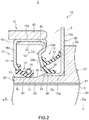
- Fig. 2 is a cross-sectional view for illustrating a schematic configuration of a sealing structure 5 according to the modification of the above-described sealing structure 1 according to the embodiment of the present invention.
- the sealing structure 5 according to the present modification is different from the above-described sealing structure 1 in the shape of a dust cover.
- any component identical or similar to that of the above-described sealing structure 1 is denoted by an identical reference sign, description thereof will be omitted, and any different part will be described.
- the sealing structure 5 according to the present modification includes a dust cover 60 that is different from the dust cover 13 of the above-described sealing structure 1.
- the dust cover 60 does not include the outer peripheral flange portion 13c covering the flange portion 42 of the bracket 41 from the outer peripheral side, but only includes the inner peripheral flange portion 13a and the circular ring portion 13b.
- the dust cover 60 does not have the gap 2, the circular ring portion 13b faces to the flange portion 42 from the outer side and forms the gap 3, and a labyrinth seal is formed only at the gap 3.
- the sealing structure 5 according to the present modification can achieve an effect identical to that of the above-described sealing structure 1.
- the present invention is not limited to the above-described sealing structures 1 and 5 according to the embodiment of the present invention, but includes any aspect included in the concept of the present invention and the claims. Configurations may be selectively combined as appropriate to achieve at least part of the problem and effect described above.
- the shape, material, disposition, and size of each component in the above-described embodiment may be changed as appropriate in accordance with a specific usage form of the present invention.
- the sealing device 10 needs to be attached to one of the shaft 40 and the rotational body 50 in a relatively irrotational manner, the contacted portion 30 needs to be formed in the other of the shaft 40 and the rotational body 50 in a relatively irrotational manner, the sealing device 10 is not limited to the attachment to the flange portion 42 of the bracket 41 as described above, and the contacted portion 30 is not limited to the formation in the inner side end portion 52 of the rotational body 50 as described above.
- the sealing device 10 and the contacted portion 30 may have shapes inverted in the directions of the outer peripheral side and the inner peripheral side in Figs. 1 and 2 .
- the inner side attachment ring 14 of the sealing device 10 may be fitted to the inner side end portion 52 of the rotational body 50, and the inner side seal lip 15 thereof may abut the inner peripheral surface 44 of the flange portion 42 of the bracket 41.
- the contacted portion 30 is formed in the inner peripheral surface 44 of the flange portion 42 of the bracket 41, and the dust cover 60 illustrated in Fig. 2 is fitted to the inner peripheral surface 44 of the flange portion 42 of the bracket 41.
- a gap is formed between an end portion of a disk portion 13b of the dust cover 60 on the inner peripheral side and the inner side end portion 52 of the rotational body 50, and a labyrinth seal is formed.
- the sealing device 10 may be disposed between the rotational body 50 and the shaft 40, the inner side attachment ring 14 may be fitted onto an inner peripheral surface of the through-hole 51 of the rotational body 50, and the inner side seal lip 15 may abut an outer peripheral surface of the shaft 40.
- the contacted portion 30 is formed on an outer peripheral surface of the shaft 40, and the dust cover 13 or 50 forms the gaps 2 and 3 or the gap 3 between the dust cover 13 or 50 and an end portion of the rotational body 50 on the outer side.
- a sleeve may be fitted to the shaft 40, and the contacted portion 30 may be formed on the sleeve.
- the sealing device 10 may be disposed between the rotational body 50 and the shaft 40, the inner side attachment ring 14 may be fitted onto the outer peripheral surface of the shaft 40, and the inner side seal lip 15 may abut the inner peripheral surface of the through-hole 51 of the rotational body 50.
- the contacted portion 30 is formed on the inner peripheral surface of the through-hole 51 of the rotational body 50, and the dust cover 60 illustrated in Fig. 2 is fitted onto the inner peripheral surface of the through-hole 51 of the rotational body 50.
- a gap is formed between an end portion of the disk portion 13b of the dust cover 60 on the inner peripheral side and the outer peripheral surface of the shaft 40, and a labyrinth seal is formed.
- sealing structures 1 and 5 are used at the trunnion suspension of a truck in the above description
- the sealing structures according to the present invention are not limited to a sealing structure at the trunnion suspension of a truck, but are applicable to a mechanism of the same kind such as what is called a chassis component in a truck or another vehicle, a general industrial machine, a farming machine, and a construction machine.
Landscapes
- Engineering & Computer Science (AREA)
- General Engineering & Computer Science (AREA)
- Mechanical Engineering (AREA)
- Sealing With Elastic Sealing Lips (AREA)
- Sealing Of Bearings (AREA)
- Sealing Devices (AREA)
- Sealing Using Fluids, Sealing Without Contact, And Removal Of Oil (AREA)
Abstract
Description
- The present invention relates to a sealing structure, and particularly relates to a sealing structure in which replenishment of lubricant used for, for example, a suspension of a truck is performed.
- Conventionally, in a mechanism having a rotational axis, a sealing structure has been used to achieve prevention of entrance of foreign matter such as muddy water, rainwater, and dust from the outside while achieving prevention of leakage of lubricant from the inside, and examples of such sealing structures include a sealing structure in which replenishment of lubricant from the outside is possible. For example, in a trunnion suspension used for a rear wheel of a truck, a sealing structure is provided to seal a space between a shaft attached to a frame of a vehicle body and an attachment hole of a leaf spring into which the shaft is inserted in a freely rotatable manner. The space between the shaft and the attachment hole of the leaf spring is provided with a sliding bearing and filled with lubricant to form a slide portion, and the sealing structure is provided to achieve prevention of leakage of the lubricant from the slide portion and prevention of entrance of any foreign matter from the outside into the slide portion. Examples of such a conventional sealing structure include a sealing structure that allows supply (replenishment) of lubricant from the outside (see
Patent Literature 1, for example). - In such a conventional sealing structure at the trunnion suspension of a truck, a seal lip of a sealing device, which is formed of an elastic body that directly or indirectly abuts, for example, an outer peripheral surface of a trunnion shaft in a slidable manner. Accordingly, sealing of a space between the trunnion shaft and the leaf spring is achieved, and prevention of leakage of the lubricant and prevention of entrance of any foreign matter into the inside are achieved. The lubricant is applied to the seal lip, and the seal lip is supplied and replenished with the lubricant along with replenishment of the slide portion of the trunnion shaft with the lubricant in response to consumption of the lubricant. The seal lip is pressed and moved by the lubricant supplied from the inside upon the replenishment of the lubricant, and the seal lip extends toward the outer sides so that the seal lip does not deform and roll back upon the replenishment.
- Patent Literature 1: Japanese Utility Model Application Publication
62-139705 - In such a conventional sealing structure, achievement of prevention of entrance of any foreign matter from the outer side is attempted while preventing abrasion of the slide portion between the seal lip and the trunnion shaft by supply of lubricant. However, maintenance of a sealing performance under a more severe environment has been required for the sealing structure due to diversification of use environment of vehicles such as a truck, and further improvement of sealing performance against foreign matter has been required.
- The present invention has been made in view of the above-described problem, and it is an object of the present invention to provide a sealing structure that can improve sealing performance against foreign matter such as muddy water, rainwater, and dust.
- To achieve the above-described object, a sealing structure according to the present invention is a sealing structure for sealing a space between a shaft extending in an axis direction and a rotational body in which a through-hole extending in the axis direction is formed and the shaft is inserted through the through-hole with a space, the sealing structure is characterized in including a sealing device attached to one of the shaft and the rotational body in a relatively irrotational manner, and a contacted portion formed in the other of the shaft and the rotational body in a relatively irrotational manner. The sealing device includes an inner side seal portion, an outer side seal portion, and a dust cover, the contacted portion includes a peripheral surface in an annular shape centered about the axis, the inner side seal portion includes an inner side attachment ring having an annular shape centered about the axis and attached to the one of the shaft and the rotational body in a relatively irrotational manner, and an inner side seal lip formed of an elastic body having an annular shape centered about the axis and attached to the inner side attachment ring, the inner side seal lip extending from the inner side attachment ring toward an outer side that is a side toward which one direction along the axis direction faces, and slidably abuts the contacted portion at a part on the outer side, the outer side seal portion includes an outer side attachment ring having an annular shape centered about the axis and fitted to the inner side attachment ring of the inner side seal portion, an outer side seal lip formed of an elastic body having an annular shape centered about the axis and attached to the outer side attachment ring, and a side lip formed of an elastic body having an annular shape centered about the axis and attached to the outer side attachment ring on a side separate from the contacted portion than the outer side seal lip, the outer side seal lip is positioned on the outer side of the inner side seal lip, extends from the outer side attachment ring toward the outer side, and slidably abuts the dust cover at a part on the outer side, the side lip extends from the outer side attachment ring toward the outer side and slidably abuts the dust cover at an end portion on the outer side, and the dust cover is an annular member attached to a peripheral surface of the contacted portion and forms a gap between the dust cover and a member to which the inner side attachment ring is attached.
- In the sealing structure according to an aspect of the present invention, the peripheral surface of the contacted portion includes an annular transition portion that approaches toward an sealing device side as the peripheral surface progresses toward the outer side, and the transition portion is positioned between the inner side seal lip and the outer side seal lip.
- In the sealing structure according to an aspect of the present invention, the sealing device is fitted to a bracket holding the shaft on an outer peripheral side, the contacted portion is formed at an end portion of the rotational body on an inner side, the peripheral surface of the contacted portion is a surface facing toward the outer peripheral side, and the dust cover forms the gap between the dust cover and the bracket at an end portion on the outer peripheral side.
- In the sealing structure according to an aspect of the present invention, in the outer side attachment ring, a part to which the side lip is attached is positioned on an inner side of an end portion, on the outer side, of a part attached to the inner side attachment ring.
- In the sealing structure according to an aspect of the present invention, the dust cover is made of stainless steel.
- A sealing structure according to the present invention can improve sealing performance for foreign matter such as muddy water, rainwater, and dust.
-
- [
Fig. 1] Fig. 1 is a cross-sectional view at a section along an axis x for illustrating a schematic configuration of a sealing structure according to an embodiment of the present invention. - [
Fig. 2] Fig. 2 is a cross-sectional view for illustrating a schematic configuration of a sealing structure according to a modification of the sealing structure according to the embodiment of the present invention illustrated inFig. 1 . - An embodiment of the present invention will be described below in detail with reference to the drawings.
-
Fig. 1 is a cross-sectional view at a section along an axis x for illustrating a schematic configuration of a sealingstructure 1 according to an embodiment of the present invention. InFig. 1 , a part of a section along the axis x (hereinafter also simply referred to as a "section") of the sealingstructure 1 is illustrated. The sealingstructure 1 according to the present embodiment is a sealing structure for sealing a space between a trunnion shaft and a rotational body on which a leaf spring is held at a trunnion suspension of a truck. - As illustrated in
Fig. 1 , the sealingstructure 1 includes a sealingdevice 10 and a contactedportion 30, and is used to seal a space between ashaft 40 as a trunnion shaft extending in the direction of the axis x and arotational body 50 as a spring sheet. Specifically, a leaf spring (not illustrated) is attached to therotational body 50 and held by therotational body 50, and a through-hole 51 extending in the direction of the axis x is formed in therotational body 50. Theshaft 40 is inserted through the through-hole 51 of therotational body 50 with a space. The sealingstructure 1 seals a space g between therotational body 50 and theshaft 40. Theshaft 40 is fixed to abracket 41 fixed to a frame of a vehicle body (not illustrated), thebracket 41 includes anannular flange portion 42 centered about the axis x and covering theshaft 40 on an outer peripheral side, and aspace 43 on an inner peripheral side of theflange portion 42 communicates with the space g between therotational body 50 and theshaft 40 on an inner side. In the trunnion suspension, the sealingdevice 10 is attached to one of theshaft 40 and therotational body 50 in a relatively irrotational manner, and the contactedportion 30 is formed in the other of theshaft 40 and therotational body 50 in a relatively irrotational manner. An outer side is assumed as a side toward which one direction (the direction of arrow a inFig. 1 ) along the direction of the axis x faces, and the inner side is assumed as a side toward which the other direction (the direction of arrow b inFig. 1 ) along the direction of the axis x faces. In other words, the outer side is a side toward which theshaft 40 extends relative to thebracket 41. - Specifically, the
rotational body 50 accommodates a part of theshaft 40 in the through-hole 51, and is freely rotatable about theshaft 40, and a leaf spring is fixed to therotational body 50 by, for example, a U bolt. Therotational body 50 allows the leaf spring to swing about a center at theshaft 40. As illustrated inFig. 1 , an innerside end portion 52 as a part of an edge of therotational body 50 on the inner side has a cylindrical shape centered about the axis x, and theflange portion 42 of thebracket 41 surrounds the innerside end portion 52 on the outer peripheral side, thereby forming thespace 43. A sliding bearing (not illustrated) such as a metal bush is provided to form a slide portion in the space g between therotational body 50 and theshaft 40, and the space g is filled with lubricant and lubricant is applied on the sliding bearing. The lubricant is, for example, grease. Accordingly, therotational body 50 can smoothly rotate around theshaft 40. For example, a groove extending along the axis x is formed in the sliding bearing, and the grease can be supplied to the sliding bearing through a lubricant supply port (not illustrated) provided to therotational body 50, and the grease can be supplied to the sealingdevice 10. The grease can be discharged through a lubricant discharge port, not illustrated, provided to therotational body 50. - The sealing
device 10 includes an innerside seal portion 11, an outerside seal portion 12, and adust cover 13. The sealingdevice 10 is attached in a manner relatively irrotational against theshaft 40 in the present embodiment, and, specifically, is fitted to an innerperipheral surface 44 of theflange portion 42 of thebracket 41 as illustrated inFig. 1 . The contactedportion 30 includes an annularperipheral surface 31 centered about the axis x, and in the present embodiment, the contactedportion 30 is formed in a relatively irrotational manner relative to therotational body 50, and specifically, as illustrated inFig. 1 , is formed in the innerside end portion 52 of therotational body 50, and theperipheral surface 31 of the contactedportion 30 forms an outer peripheral surface of the innerside end portion 52 of therotational body 50. - The inner
side seal portion 11 includes an annular innerside attachment ring 14 centered about the axis x and fitted to the innerperipheral surface 44 of theflange portion 42 of thebracket 41 on the outer peripheral side, and an innerside seal lip 15 formed of an annular elastic body centered about the axis x and attached to the innerside attachment ring 14 on the inner peripheral side. The innerside seal lip 15 extends from the innerside attachment ring 14 toward the outer side and slidably abuts theperipheral surface 31 of the contactedportion 30 at an end portion on the outer side. More specifically, theperipheral surface 31 of the contactedportion 30 slidably contacts the innerside seal lip 15. - In the inner
side seal portion 11, specifically, as illustrated inFig. 1 , the innerside attachment ring 14 is substantially L-shaped in a sectional shape, and includes acylinder portion 14a that is a cylindrical part extending in the direction of the axis x, and aflange portion 14b that is a part having a circular ring plate shape extending from an end portion of thecylinder portion 14a on the inner side toward the inner peripheral side. Thecylinder portion 14a of the innerside attachment ring 14 is pressed and fitted to thespace 43 that theflange portion 42 of thebracket 41 forms, and an outer peripheral surface of thecylinder portion 14a makes close contact with the innerperipheral surface 44 of theflange portion 42. Accordingly, the innerside attachment ring 14 is fitted to thebracket 41. The innerside seal lip 15 is attached to an end portion of theflange portion 14b of the innerside attachment ring 14 on the inner peripheral side. - Specifically, the inner
side seal lip 15 includes an annularlip base portion 16 extending in the direction of the axis x, and an annularlip tip portion 17 formed at an end portion of thelip base portion 16 on the outer side. Thelip base portion 16 is attached to theflange portion 14b of the innerside attachment ring 14 at an end portion on the inner side. Thelip tip portion 17 is an annular part having a wedge shape, a sectional shape of which is convex toward the inner peripheral side, and slidably abuts theperipheral surface 31 of the contactedportion 30. In other words, theperipheral surface 31 of the contactedportion 30 slidably contacts thelip tip portion 17. Agarter spring 18 is fitted onto the outer peripheral side of the innerside seal lip 15 at a position facing away from thelip tip portion 17, and thegarter spring 18 presses thelip tip portion 17 of the innerside seal lip 15 toward the inner peripheral side in a radial direction and provides thelip tip portion 17 with tension force having a predetermined magnitude toward thecontacted portion 30. Thelip tip portion 17 abuts theperipheral surface 31 of the contactedportion 30 as described later, and achieves sealing between the innerside seal portion 11 and the contactedportion 30. - The outer
side seal portion 12 includes an annular outerside attachment ring 19 centered about the axis x and fitted to the innerside attachment ring 14 of the innerside seal portion 11 on the outer peripheral side, and an outerside seal lip 20 formed of an annular elastic body centered about the axis x and attached to the outerside attachment ring 19 on the inner peripheral side. The outerside seal portion 12 includes aside lip 21 formed of an annular elastic body centered about the axis x and attached to the outerside attachment ring 19 on the outer peripheral side that is a side further separated from the contactedportion 30 than the outerside seal lip 20. The outerside seal lip 20 extends from the outerside attachment ring 19 toward the outer side and slidably abuts thedust cover 13 at an end portion on the outer side as described later, and theside lip 21 extends from the outerside attachment ring 19 toward the outer side and slidably abuts thedust cover 13 at an end portion on the outer side. - Specifically, in the outer
side seal portion 12, the outerside attachment ring 19 is substantially L-shaped in sectional shape and includes acylinder portion 22 that is a cylindrical part extending in the direction of the axis x, and aflange portion 23 that is a part having a substantially circular ring plate shape and extending from an end portion of thecylinder portion 22 on the outer side toward the inner peripheral side. Thecylinder portion 22 of the outerside attachment ring 19 is pressed and fitted to the inner peripheral side of thecylinder portion 14a of the innerside attachment ring 14 fitted to thebracket 41, and an outer peripheral surface of thecylinder portion 22 closely contacts an inner peripheral surface of thecylinder portion 14a of the innerside attachment ring 14. Accordingly, the outerside attachment ring 19 is fitted to the innerside seal portion 11. The outerside seal lip 20 is attached to an end portion of theflange portion 23 of the outerside attachment ring 19 on the inner peripheral side, and theside lip 21 is attached to the outer peripheral side of the outerside seal lip 20 in the outerside attachment ring 19. - Specifically, the outer
side seal lip 20 includes an annularseal base portion 24 extending toward the outer side, and an annularlip tip portion 25 formed at an end portion of theseal base portion 24 on the outer side. Theseal base portion 24 is attached to theflange portion 23 of the outerside attachment ring 19 at an end portion on the inner side. Thelip tip portion 25 is an annular part having a wedge shape, a sectional shape of thelip tip portion 25 is convexed toward the inner peripheral side, and as described later, thelip tip portion 25 slidably abuts thedust cover 13, thereby achieving sealing between the outerside seal portion 12 and thedust cover 13. - Specifically, the
side lip 21 is an annular elastic member obliquely extending from theflange portion 23 of the outerside attachment ring 19 toward the outer side and the outer peripheral side, and has a circular cone tubular shape extending toward the outer side centered about the axis x. As illustrated inFig. 1 , theside lip 21 is integrally formed of a material identical to that of the outerside seal lip 20. Thus, theside lip 21 connects with thelip base portion 24 of the outerside seal lip 20 at an end portion on the inner side. - The inner
side attachment ring 14 of the innerside seal portion 11 and the outerside attachment ring 19 of the outerside seal portion 12 described above are each formed of a metal material, and examples of the metal material include stainless steel and SPCC (cold rolled steel sheet). Examples of the elastic body of the innerside seal lip 15 of the innerside seal portion 11, the outerside seal lip 20 of the outerside seal portion 12, and theside lip 21 include various rubber materials. Examples of the various rubber materials include synthetic rubbers such as nitrile rubber (NBR), hydrogenated nitrile rubber (H-NBR), acrylic rubber (ACM), and fluororubber (FKM). - The inner
side attachment ring 14 and the outerside attachment ring 19 are manufactured by, for example, press working or forging, and the innerside seal lip 15, the outerside seal lip 20, and theside lip 21 are each molded with a mold by cross-linking (vulcanization). During the cross-linking, the innerside attachment ring 14 and the outerside attachment ring 19 are each placed in the mold, the innerside seal lip 15 is bonded to the innerside attachment ring 14 by cross-linking bonding, the outerside seal lip 20 and theside lip 21 are bonded to the outerside attachment ring 19 by cross-linking bonding, the innerside seal lip 15 is molded integrally with the innerside attachment ring 14, and the outerside seal lip 20 and theside lip 21 are molded integrally with the outerside attachment ring 19. - The
dust cover 13 is an annular member attached to theperipheral surface 31 of the contactedportion 30, and forms a gap between thedust cover 13 and a member to which the innerside attachment ring 14 is attached. In other words, in the present embodiment, thedust cover 13 forms a gap between thedust cover 13 and theflange portion 42 of thebracket 41. Specifically, thedust cover 13 is substantially C-shaped (U-shaped) in a sectional shape, and includes an innerperipheral flange portion 13a that is a cylindrical part extending in the direction of the axis x on the inner peripheral side, acircular ring portion 13b that is a part having a circular ring plate shape and extending from an end portion of the innerperipheral flange portion 13a on the outer side toward the outer peripheral side, and an outerperipheral flange portion 13c that is a cylindrical part extending from an end portion of thecircular ring portion 13b on the outer peripheral side toward the inner side. The innerperipheral flange portion 13a of thedust cover 13 is pressed and fitted into the contactedportion 30, and an inner peripheral surface of the innerperipheral flange portion 13a closely contacts theperipheral surface 31 of the contactedportion 30. Accordingly, thedust cover 13 is fitted and fixed to the contactedportion 30. Thedust cover 13 is positioned by abutting, at an outer side surface of thecircular ring portion 13b, a side surface of an annular steppedportion 53 projecting at an outer periphery of therotational body 50. As illustrated inFig. 1 , thelip tip portion 25 of the outerside seal lip 20 slidably abuts an outer peripheral surface of the innerperipheral flange portion 13a of thedust cover 13, and a tip of theside lip 21 slidably abuts an inner side surface of thecircular ring portion 13b of thedust cover 13. More specifically, the innerperipheral flange portion 13a of thedust cover 13 slidably contacts: thelip tip portion 25 of the outerside seal lip 20, and thecircular ring portion 13b of thedust cover 13 slidably contacts the tip of theside lip 21. - As illustrated in
Fig. 1 , in theflange portion 23 of the outerside attachment ring 19, an innerperipheral portion 23b, the innerperipheral portion 23b is a part on the inner peripheral side to which theside lip 21 is attached, has a shape recessed toward the inner side so that the innerperipheral portion 23b is positioned on the inner side of an end portion of thecylinder portion 22 on the outer side or an outerperipheral portion 23a that is a part on the outer peripheral side connected with thecylinder portion 22. This shape of theflange portion 23 can provide a clearance that allows theside lip 21 to contact thedust cover 13 in a desired posture between the innerperipheral portion 23b of theflange portion 23 of the outerside attachment ring 19 and thedust cover 13 even when a clearance between the sealingdevice 10 and thedust cover 13 is small in the direction of the axis x. - As illustrated in
Fig. 1 , thedust cover 13 covers theflange portion 42 of thebracket 41 from the outer peripheral side at the outerperipheral flange portion 13c, and forms agap 2 between the outerperipheral flange portion 13c and theflange portion 42. Thedust cover 13 faces theflange portion 42 of thebracket 41 from the outer side at thecircular ring portion 13b, and forms agap 3 between thecircular ring portion 13b and theflange portion 42. Thesesmall gaps - The
dust cover 13 is made of stainless steel and has excellent rust-resistant and rust-proofing properties. Accordingly, generation of rust on the slide portions of the outerside seal lip 20 and the slide portion of theside lip 21 can be suppressed, and the sealing function and sealing performance of the outerside seal lip 20 and theside lip 21 can be maintained for a long period of time. The material of thedust cover 13 is not limited to stainless steel, but may be another metal. However, it is preferable that a surface, in particular a slide surface of the material, is provided with rust-proofing processing such as rust-proofing plating processing. - As illustrated in
Fig. 1 , the contactedportion 30 includes anannular transition portion 32 that approaches the sealingdevice 10 side as thetransition portion 32 progresses toward the outer side, and thetransition portion 32 is positioned between the innerside seal lip 15 and the outerside seal lip 20. In the present embodiment, at thetransition portion 32, the diameter of the contactedportion 30 becomes larger as the contactedportion 30 progresses from the inner side toward the outer side. Thus, a part of theperipheral surface 31 of the contactedportion 30 on the inner side of thetransition portion 32 is asmall diameter portion 33, a part of theperipheral surface 31 of the contactedportion 30 on the outer side of thetransition portion 32 is alarge diameter portion 34, and the diameter of the contactedportion 30 at thesmall diameter portion 33 is smaller than the diameter of the contactedportion 30 at thelarge diameter portion 34. Thetransition portion 32 smoothly connects thesmall diameter portion 33 and thelarge diameter portion 34. Thelip tip portion 17 of the innerside seal lip 15 abuts theperipheral surface 31 of the contactedportion 30 at thesmall diameter portion 33, and the innerperipheral flange portion 13a of thedust cover 13 is fitted to the contactedportion 30 at thelarge diameter portion 34. Specifically, the diameter of the contactedportion 30 at thetransition portion 32 becomes gradually larger and smoothly larger as the contactedportion 30 progresses toward the outer side. Thetransition portion 32 has, for example, a circular cone surface shape, and has a curved surface shape that is concaved toward the inner peripheral side or a curved surface shape that is convexed toward the outer peripheral side. - When the sealing
structure 1 is being used, it is preferable that a space between the innerside seal portion 11 and the outerside seal portion 12 of the sealingdevice 10 be filled with grease so that the slide portion of the innerside seal lip 15 and the outerside seal lip 20 are lubricated with the grease. Thus, grease is supplied through the lubricant supply port (not illustrated) provided to therotational body 50 so as to replenish the space between the innerside seal portion 11 and the outerside seal portion 12 with the grease. The supplied grease reaches the innerside seal lip 15 along theperipheral surface 31 of the contactedportion 30 through a space of the through-hole 51, presses and removes thelip tip portion 17 toward the outer peripheral side, and reaches the space between the innerside seal portion 11 and the outerside seal portion 12. Since thetransition portion 32 extending toward the outer peripheral side is formed between the innerside seal lip 15 and the outerside seal lip 20 on theperipheral surface 31 of the contactedportion 30, the supplied grease is guided to the outer peripheral side along thetransition portion 32 so that the grease is likely to be supplied between the innerside seal portion 11 and the outerside seal portion 12. Thetransition portion 32 can reduce flow path resistance for the grease upon supply of the grease. In this manner, in the sealingstructure 1, replenishment of the space between the innerside seal portion 11 and the outerside seal portion 12 with grease can be easily and efficiently performed through thetransition portion 32 included in the contactedportion 30. - Since the contacted
portion 30 includes thetransition portion 32, thedust cover 13 can be suppressed from contacting theperipheral surface 31 at thesmall diameter portion 33 upon attachment of thedust cover 13 to be attached to thelarge diameter portion 34, thereby suppressing damage on theperipheral surface 31 at thesmall diameter portion 33 of the contactedportion 30 that is a contact portion of the innerside seal lip 15. - According to the sealing
structure 1 having the above-described configuration, thedust cover 13 forms thesmall gaps dust cover 13 and theflange portion 42 of thebracket 41 to which thesealing device 10 is fitted, and thegaps structure 1 can be prevented on an upstream side on an entrance path for foreign matter by the labyrinth seal, and sealing performance against foreign matter can be improved. - In the sealing
structure 1, in addition to the outerside seal lip 20, theside lip 21 is provided upstream of the outerside seal lip 20 on the entrance path for foreign matter, and theside lip 21 abuts thedust cover 13 and cuts off the entrance path for foreign matter. Thus, entrance of foreign matter into the inside of the sealingstructure 1 can be further prevented, and the sealing performance against foreign matter can be further improved. - In the sealing
structure 1, since thedust cover 13 is provided as a contact portion of theside lip 21, contact of theside lip 21 can be maintained when displacement of theside lip 21 in the direction of the axis x or decentering thereof from the axis x occurs, irrespective of the shape of therotational body 50, for example, when a projection width of the steppedportion 53 of therotational body 50 from theperipheral surface 31 of the contactedportion 30 in the radial direction is small. - In this manner, the sealing
structure 1 according to the embodiment of the present invention can improve the sealing performance against foreign matter. - The following describes a modification of the above-described
sealing structure 1 according to the embodiment of the present invention.Fig. 2 is a cross-sectional view for illustrating a schematic configuration of a sealing structure 5 according to the modification of the above-describedsealing structure 1 according to the embodiment of the present invention. The sealing structure 5 according to the present modification is different from the above-describedsealing structure 1 in the shape of a dust cover. Hereinafter, any component identical or similar to that of the above-describedsealing structure 1 is denoted by an identical reference sign, description thereof will be omitted, and any different part will be described. - As illustrated in
Fig. 2 , the sealing structure 5 according to the present modification includes adust cover 60 that is different from thedust cover 13 of the above-describedsealing structure 1. Unlike the above-describeddust cover 13, thedust cover 60 does not include the outerperipheral flange portion 13c covering theflange portion 42 of thebracket 41 from the outer peripheral side, but only includes the innerperipheral flange portion 13a and thecircular ring portion 13b. Thus, thedust cover 60 does not have thegap 2, thecircular ring portion 13b faces to theflange portion 42 from the outer side and forms thegap 3, and a labyrinth seal is formed only at thegap 3. The sealing structure 5 according to the present modification can achieve an effect identical to that of the above-describedsealing structure 1. - Although the embodiment of the present invention is described above, the present invention is not limited to the above-described
sealing structures 1 and 5 according to the embodiment of the present invention, but includes any aspect included in the concept of the present invention and the claims. Configurations may be selectively combined as appropriate to achieve at least part of the problem and effect described above. For example, the shape, material, disposition, and size of each component in the above-described embodiment may be changed as appropriate in accordance with a specific usage form of the present invention. - For example, the sealing
device 10 needs to be attached to one of theshaft 40 and therotational body 50 in a relatively irrotational manner, the contactedportion 30 needs to be formed in the other of theshaft 40 and therotational body 50 in a relatively irrotational manner, the sealingdevice 10 is not limited to the attachment to theflange portion 42 of thebracket 41 as described above, and the contactedportion 30 is not limited to the formation in the innerside end portion 52 of therotational body 50 as described above. - For example, the sealing
device 10 and the contactedportion 30 may have shapes inverted in the directions of the outer peripheral side and the inner peripheral side inFigs. 1 and2 . In other words, the innerside attachment ring 14 of the sealingdevice 10 may be fitted to the innerside end portion 52 of therotational body 50, and the innerside seal lip 15 thereof may abut the innerperipheral surface 44 of theflange portion 42 of thebracket 41. In this case, the contactedportion 30 is formed in the innerperipheral surface 44 of theflange portion 42 of thebracket 41, and thedust cover 60 illustrated inFig. 2 is fitted to the innerperipheral surface 44 of theflange portion 42 of thebracket 41. A gap is formed between an end portion of adisk portion 13b of thedust cover 60 on the inner peripheral side and the innerside end portion 52 of therotational body 50, and a labyrinth seal is formed. - For example, the sealing
device 10 may be disposed between therotational body 50 and theshaft 40, the innerside attachment ring 14 may be fitted onto an inner peripheral surface of the through-hole 51 of therotational body 50, and the innerside seal lip 15 may abut an outer peripheral surface of theshaft 40. In this case, the contactedportion 30 is formed on an outer peripheral surface of theshaft 40, and thedust cover gaps gap 3 between thedust cover rotational body 50 on the outer side. In this case, a sleeve may be fitted to theshaft 40, and the contactedportion 30 may be formed on the sleeve. - For example, the sealing
device 10 may be disposed between therotational body 50 and theshaft 40, the innerside attachment ring 14 may be fitted onto the outer peripheral surface of theshaft 40, and the innerside seal lip 15 may abut the inner peripheral surface of the through-hole 51 of therotational body 50. In this case, the contactedportion 30 is formed on the inner peripheral surface of the through-hole 51 of therotational body 50, and thedust cover 60 illustrated inFig. 2 is fitted onto the inner peripheral surface of the through-hole 51 of therotational body 50. A gap is formed between an end portion of thedisk portion 13b of thedust cover 60 on the inner peripheral side and the outer peripheral surface of theshaft 40, and a labyrinth seal is formed. - Although the sealing
structures 1 and 5 according to the embodiment of the present invention are used at the trunnion suspension of a truck in the above description, the sealing structures according to the present invention are not limited to a sealing structure at the trunnion suspension of a truck, but are applicable to a mechanism of the same kind such as what is called a chassis component in a truck or another vehicle, a general industrial machine, a farming machine, and a construction machine. -
- 1, 5, 100
- sealing structure
- 2, 3
- gap
- 10
- sealing device
- 11
- inner side seal portion
- 12
- outer side seal portion
- 13, 60
- dust cover
- 13a
- inner peripheral flange portion
- 13b
- circular ring portion
- 13c
- outer peripheral flange portion
- 14
- inner side attachment ring
- 15
- inner side seal lip
- 17, 25
- lip tip portion
- 19
- outer side attachment ring
- 20
- outer side seal lip
- 21
- side lip
- 30
- contacted portion
- 31
- peripheral surface
- 32
- transition portion
- 40
- shaft
- 41
- bracket
- 42
- flange portion
- 43
- space
- 44
- inner peripheral surface
- 50
- rotational body
- 51
- through-hole
- 52
- inner side end portion
Claims (5)
- A sealing structure for sealing a space between a shaft extending in an axis direction and a rotational body in which a through-hole extending in the axis direction is formed and the shaft is inserted through the through-hole with a space, the sealing structure characterized in comprising:a sealing device attached to one of the shaft and the rotational body in a relatively irrotational manner;a contacted portion formed in another of the shaft and the rotational body in a relatively irrotational manner, whereinthe sealing device includes an inner side seal portion, an outer side seal portion, and a dust cover,the contacted portion includes a peripheral surface in an annular shape centered about the axis,the inner side seal portion includes an inner side attachment ring having an annular shape centered about the axis and attached to the one of the shaft and the rotational body in a relatively irrotational manner, and an inner side seal lip formed of an elastic body having an annular shape centered about the axis and attached to the inner side attachment ring, and the inner side seal lip extends from the inner side attachment ring toward an outer side that is a side toward which one direction along the axis direction faces, and slidably abuts the contacted portion at a part on the outer side,the outer side seal portion includes an outer side attachment ring having an annular shape centered about the axis and fitted to the inner side attachment ring of the inner side seal portion, an outer side seal lip formed of an elastic body having an annular shape centered about the axis and attached to the outer side attachment ring, and a side lip formed of an elastic body having an annular shape centered about the axis and attached to the outer side attachment ring on a side separate from the contacted portion than the outer side seal lip, the outer side seal lip is positioned on the outer side of the inner side seal lip, extends from the outer side attachment ring toward the outer side, and slidably abuts the dust cover at a part on the outer side, and the side lip extends from the outer side attachment ring toward the outer side and slidably abuts the dust cover at an end portion on the outer side, andthe dust cover is an annular member attached to a peripheral surface of the contacted portion and forms a gap between the dust cover and a member to which the inner side attachment ring is attached.
- The sealing structure according to claim 1, characterized in that the peripheral surface of the contacted portion includes an annular transition portion that approaches toward an sealing device side as the peripheral surface progresses toward the outer side, and the transition portion is positioned between the inner side seal lip and the outer side seal lip.
- The sealing device according to claim 1 or 2, characterized in that the sealing device is fitted to a bracket holding the shaft on an outer peripheral side, the contacted portion is formed at an end portion of the rotational body on an inner side, the peripheral surface of the contacted portion is a surface facing toward the outer peripheral side, and the dust cover forms the gap between the dust cover and the bracket at an end portion on the outer peripheral side.
- The sealing structure according to any one of claims 1 to 3, characterized in that, in the outer side attachment ring, a part to which the side lip is attached is positioned on an inner side of an end portion, on the outer side, of a part attached to the inner side attachment ring.
- The sealing structure according to any one of claims 1 to 4, characterized in that the dust cover is made of stainless steel.
Applications Claiming Priority (2)
| Application Number | Priority Date | Filing Date | Title |
|---|---|---|---|
| JP2015174180 | 2015-09-03 | ||
| PCT/JP2016/075166 WO2017038752A1 (en) | 2015-09-03 | 2016-08-29 | Sealing structure |
Publications (3)
| Publication Number | Publication Date |
|---|---|
| EP3327322A1 true EP3327322A1 (en) | 2018-05-30 |
| EP3327322A4 EP3327322A4 (en) | 2019-03-27 |
| EP3327322B1 EP3327322B1 (en) | 2020-03-25 |
Family
ID=58187502
Family Applications (1)
| Application Number | Title | Priority Date | Filing Date |
|---|---|---|---|
| EP16841784.8A Active EP3327322B1 (en) | 2015-09-03 | 2016-08-29 | Sealing structure |
Country Status (6)
| Country | Link |
|---|---|
| US (1) | US10473219B2 (en) |
| EP (1) | EP3327322B1 (en) |
| JP (1) | JP6094953B1 (en) |
| KR (1) | KR102037705B1 (en) |
| CN (1) | CN107923536B (en) |
| WO (1) | WO2017038752A1 (en) |
Families Citing this family (2)
| Publication number | Priority date | Publication date | Assignee | Title |
|---|---|---|---|---|
| CN111981108B (en) * | 2020-08-31 | 2021-11-02 | 温州职业技术学院 | A gear reducer device with dustproof function |
| DE112021008214T5 (en) * | 2021-09-06 | 2024-07-18 | Schaeffler Technologies AG & Co. KG | Sealing structure for an in-wheel electric motor drive system and in-wheel electric motor drive system |
Family Cites Families (17)
| Publication number | Priority date | Publication date | Assignee | Title |
|---|---|---|---|---|
| JPS62139705U (en) | 1986-02-27 | 1987-09-03 | ||
| DE3826628A1 (en) * | 1988-08-05 | 1990-02-08 | Goetze Ag | Shaft-sealing system |
| JPH0594573U (en) * | 1992-05-21 | 1993-12-24 | エヌオーケー株式会社 | Sealing device |
| JP2591553Y2 (en) * | 1993-04-14 | 1999-03-03 | 日産ディーゼル工業株式会社 | Dustproof device for final reduction gears for vehicles |
| KR100602059B1 (en) * | 2003-05-16 | 2006-07-14 | 셰플러코리아(유) | Double Seal for Bearing |
| ATE405776T1 (en) * | 2004-07-09 | 2008-09-15 | Freudenberg Carl Kg | SHAFT SEAL |
| JP2006145015A (en) | 2004-11-25 | 2006-06-08 | Nok Corp | Sealing device |
| WO2009130933A1 (en) * | 2008-04-25 | 2009-10-29 | Nok株式会社 | Sealing device |
| JP5158389B2 (en) | 2008-11-28 | 2013-03-06 | Nok株式会社 | Sealing device |
| CN202251974U (en) * | 2011-08-04 | 2012-05-30 | 青岛开世密封工业有限公司 | Main gear oil seal for engineering bridge |
| JP5896115B2 (en) * | 2011-11-25 | 2016-03-30 | Nok株式会社 | Sealing device |
| JP6036215B2 (en) | 2011-11-29 | 2016-11-30 | 日本精工株式会社 | Rolling bearing unit with combination seal ring |
| JP6081179B2 (en) | 2012-12-14 | 2017-02-15 | Nok株式会社 | Sealing device |
| JP6080675B2 (en) * | 2013-04-26 | 2017-02-15 | 光洋シーリングテクノ株式会社 | Sealing device |
| JP6401567B2 (en) | 2013-10-21 | 2018-10-10 | Nok株式会社 | Sealing device |
| JP6201769B2 (en) | 2014-01-15 | 2017-09-27 | 日本精工株式会社 | Rolling bearing unit for seal ring and wheel support with seal ring |
| WO2015178292A1 (en) * | 2014-05-20 | 2015-11-26 | Nok株式会社 | Sealing device |
-
2016
- 2016-08-29 JP JP2016568074A patent/JP6094953B1/en active Active
- 2016-08-29 KR KR1020187005601A patent/KR102037705B1/en active Active
- 2016-08-29 CN CN201680048751.8A patent/CN107923536B/en active Active
- 2016-08-29 EP EP16841784.8A patent/EP3327322B1/en active Active
- 2016-08-29 WO PCT/JP2016/075166 patent/WO2017038752A1/en not_active Ceased
-
2018
- 2018-02-21 US US15/901,189 patent/US10473219B2/en active Active
Also Published As
| Publication number | Publication date |
|---|---|
| WO2017038752A1 (en) | 2017-03-09 |
| US20180180184A1 (en) | 2018-06-28 |
| JP6094953B1 (en) | 2017-03-15 |
| KR102037705B1 (en) | 2019-10-29 |
| CN107923536B (en) | 2018-11-20 |
| CN107923536A (en) | 2018-04-17 |
| EP3327322B1 (en) | 2020-03-25 |
| EP3327322A4 (en) | 2019-03-27 |
| JPWO2017038752A1 (en) | 2017-08-31 |
| US10473219B2 (en) | 2019-11-12 |
| KR20180033280A (en) | 2018-04-02 |
Similar Documents
| Publication | Publication Date | Title |
|---|---|---|
| US10663003B2 (en) | Sealing apparatus | |
| EP3336395B1 (en) | Sealing device | |
| EP3339693B1 (en) | Sealing apparatus | |
| US10473219B2 (en) | Sealing structure | |
| JP5896115B2 (en) | Sealing device | |
| JP7311614B2 (en) | sealing device | |
| EP3536997B1 (en) | Sealing apparatus and sealing structure | |
| JP6566384B2 (en) | Sealing device | |
| JP2016080020A (en) | Sealing device | |
| JP6955981B2 (en) | Dust seal | |
| JP6628207B2 (en) | Sealing device | |
| JP6743378B2 (en) | Auxiliary seal for sealing device | |
| JP2011074989A (en) | Dynamic seal | |
| JP7224248B2 (en) | sealing device | |
| WO2025033414A1 (en) | Sealing device | |
| JP6853367B2 (en) | Sealing device | |
| WO2025033412A1 (en) | Sealing device | |
| JP6368152B2 (en) | Sealing device | |
| JP6516199B2 (en) | Sealing device | |
| JP2020186747A (en) | Sealing device |
Legal Events
| Date | Code | Title | Description |
|---|---|---|---|
| STAA | Information on the status of an ep patent application or granted ep patent |
Free format text: STATUS: THE INTERNATIONAL PUBLICATION HAS BEEN MADE |
|
| PUAI | Public reference made under article 153(3) epc to a published international application that has entered the european phase |
Free format text: ORIGINAL CODE: 0009012 |
|
| STAA | Information on the status of an ep patent application or granted ep patent |
Free format text: STATUS: REQUEST FOR EXAMINATION WAS MADE |
|
| 17P | Request for examination filed |
Effective date: 20180223 |
|
| AK | Designated contracting states |
Kind code of ref document: A1 Designated state(s): AL AT BE BG CH CY CZ DE DK EE ES FI FR GB GR HR HU IE IS IT LI LT LU LV MC MK MT NL NO PL PT RO RS SE SI SK SM TR |
|
| AX | Request for extension of the european patent |
Extension state: BA ME |
|
| DAV | Request for validation of the european patent (deleted) | ||
| DAX | Request for extension of the european patent (deleted) | ||
| A4 | Supplementary search report drawn up and despatched |
Effective date: 20190222 |
|
| RIC1 | Information provided on ipc code assigned before grant |
Ipc: F16J 15/447 20060101ALI20190218BHEP Ipc: F16J 15/3256 20160101ALI20190218BHEP Ipc: F16J 15/3232 20160101AFI20190218BHEP |
|
| GRAP | Despatch of communication of intention to grant a patent |
Free format text: ORIGINAL CODE: EPIDOSNIGR1 |
|
| STAA | Information on the status of an ep patent application or granted ep patent |
Free format text: STATUS: GRANT OF PATENT IS INTENDED |
|
| RIC1 | Information provided on ipc code assigned before grant |
Ipc: F16J 15/3232 20160101AFI20191008BHEP Ipc: F16J 15/3256 20160101ALI20191008BHEP Ipc: F16J 15/447 20060101ALI20191008BHEP |
|
| INTG | Intention to grant announced |
Effective date: 20191030 |
|
| GRAS | Grant fee paid |
Free format text: ORIGINAL CODE: EPIDOSNIGR3 |
|
| GRAA | (expected) grant |
Free format text: ORIGINAL CODE: 0009210 |
|
| STAA | Information on the status of an ep patent application or granted ep patent |
Free format text: STATUS: THE PATENT HAS BEEN GRANTED |
|
| AK | Designated contracting states |
Kind code of ref document: B1 Designated state(s): AL AT BE BG CH CY CZ DE DK EE ES FI FR GB GR HR HU IE IS IT LI LT LU LV MC MK MT NL NO PL PT RO RS SE SI SK SM TR |
|
| REG | Reference to a national code |
Ref country code: GB Ref legal event code: FG4D |
|
| REG | Reference to a national code |
Ref country code: AT Ref legal event code: REF Ref document number: 1248934 Country of ref document: AT Kind code of ref document: T Effective date: 20200415 Ref country code: IE Ref legal event code: FG4D |
|
| REG | Reference to a national code |
Ref country code: DE Ref legal event code: R096 Ref document number: 602016032725 Country of ref document: DE |
|
| PG25 | Lapsed in a contracting state [announced via postgrant information from national office to epo] |
Ref country code: RS Free format text: LAPSE BECAUSE OF FAILURE TO SUBMIT A TRANSLATION OF THE DESCRIPTION OR TO PAY THE FEE WITHIN THE PRESCRIBED TIME-LIMIT Effective date: 20200325 Ref country code: FI Free format text: LAPSE BECAUSE OF FAILURE TO SUBMIT A TRANSLATION OF THE DESCRIPTION OR TO PAY THE FEE WITHIN THE PRESCRIBED TIME-LIMIT Effective date: 20200325 Ref country code: NO Free format text: LAPSE BECAUSE OF FAILURE TO SUBMIT A TRANSLATION OF THE DESCRIPTION OR TO PAY THE FEE WITHIN THE PRESCRIBED TIME-LIMIT Effective date: 20200625 |
|
| PG25 | Lapsed in a contracting state [announced via postgrant information from national office to epo] |
Ref country code: SE Free format text: LAPSE BECAUSE OF FAILURE TO SUBMIT A TRANSLATION OF THE DESCRIPTION OR TO PAY THE FEE WITHIN THE PRESCRIBED TIME-LIMIT Effective date: 20200325 Ref country code: HR Free format text: LAPSE BECAUSE OF FAILURE TO SUBMIT A TRANSLATION OF THE DESCRIPTION OR TO PAY THE FEE WITHIN THE PRESCRIBED TIME-LIMIT Effective date: 20200325 Ref country code: GR Free format text: LAPSE BECAUSE OF FAILURE TO SUBMIT A TRANSLATION OF THE DESCRIPTION OR TO PAY THE FEE WITHIN THE PRESCRIBED TIME-LIMIT Effective date: 20200626 Ref country code: LV Free format text: LAPSE BECAUSE OF FAILURE TO SUBMIT A TRANSLATION OF THE DESCRIPTION OR TO PAY THE FEE WITHIN THE PRESCRIBED TIME-LIMIT Effective date: 20200325 Ref country code: BG Free format text: LAPSE BECAUSE OF FAILURE TO SUBMIT A TRANSLATION OF THE DESCRIPTION OR TO PAY THE FEE WITHIN THE PRESCRIBED TIME-LIMIT Effective date: 20200625 |
|
| REG | Reference to a national code |
Ref country code: NL Ref legal event code: MP Effective date: 20200325 |
|
| REG | Reference to a national code |
Ref country code: LT Ref legal event code: MG4D |
|
| PG25 | Lapsed in a contracting state [announced via postgrant information from national office to epo] |
Ref country code: NL Free format text: LAPSE BECAUSE OF FAILURE TO SUBMIT A TRANSLATION OF THE DESCRIPTION OR TO PAY THE FEE WITHIN THE PRESCRIBED TIME-LIMIT Effective date: 20200325 |
|
| PG25 | Lapsed in a contracting state [announced via postgrant information from national office to epo] |
Ref country code: RO Free format text: LAPSE BECAUSE OF FAILURE TO SUBMIT A TRANSLATION OF THE DESCRIPTION OR TO PAY THE FEE WITHIN THE PRESCRIBED TIME-LIMIT Effective date: 20200325 Ref country code: CZ Free format text: LAPSE BECAUSE OF FAILURE TO SUBMIT A TRANSLATION OF THE DESCRIPTION OR TO PAY THE FEE WITHIN THE PRESCRIBED TIME-LIMIT Effective date: 20200325 Ref country code: SK Free format text: LAPSE BECAUSE OF FAILURE TO SUBMIT A TRANSLATION OF THE DESCRIPTION OR TO PAY THE FEE WITHIN THE PRESCRIBED TIME-LIMIT Effective date: 20200325 Ref country code: IS Free format text: LAPSE BECAUSE OF FAILURE TO SUBMIT A TRANSLATION OF THE DESCRIPTION OR TO PAY THE FEE WITHIN THE PRESCRIBED TIME-LIMIT Effective date: 20200725 Ref country code: LT Free format text: LAPSE BECAUSE OF FAILURE TO SUBMIT A TRANSLATION OF THE DESCRIPTION OR TO PAY THE FEE WITHIN THE PRESCRIBED TIME-LIMIT Effective date: 20200325 Ref country code: PT Free format text: LAPSE BECAUSE OF FAILURE TO SUBMIT A TRANSLATION OF THE DESCRIPTION OR TO PAY THE FEE WITHIN THE PRESCRIBED TIME-LIMIT Effective date: 20200818 Ref country code: SM Free format text: LAPSE BECAUSE OF FAILURE TO SUBMIT A TRANSLATION OF THE DESCRIPTION OR TO PAY THE FEE WITHIN THE PRESCRIBED TIME-LIMIT Effective date: 20200325 Ref country code: EE Free format text: LAPSE BECAUSE OF FAILURE TO SUBMIT A TRANSLATION OF THE DESCRIPTION OR TO PAY THE FEE WITHIN THE PRESCRIBED TIME-LIMIT Effective date: 20200325 |
|
| REG | Reference to a national code |
Ref country code: AT Ref legal event code: MK05 Ref document number: 1248934 Country of ref document: AT Kind code of ref document: T Effective date: 20200325 |
|
| REG | Reference to a national code |
Ref country code: DE Ref legal event code: R097 Ref document number: 602016032725 Country of ref document: DE |
|
| PG25 | Lapsed in a contracting state [announced via postgrant information from national office to epo] |
Ref country code: AT Free format text: LAPSE BECAUSE OF FAILURE TO SUBMIT A TRANSLATION OF THE DESCRIPTION OR TO PAY THE FEE WITHIN THE PRESCRIBED TIME-LIMIT Effective date: 20200325 Ref country code: DK Free format text: LAPSE BECAUSE OF FAILURE TO SUBMIT A TRANSLATION OF THE DESCRIPTION OR TO PAY THE FEE WITHIN THE PRESCRIBED TIME-LIMIT Effective date: 20200325 Ref country code: ES Free format text: LAPSE BECAUSE OF FAILURE TO SUBMIT A TRANSLATION OF THE DESCRIPTION OR TO PAY THE FEE WITHIN THE PRESCRIBED TIME-LIMIT Effective date: 20200325 Ref country code: IT Free format text: LAPSE BECAUSE OF FAILURE TO SUBMIT A TRANSLATION OF THE DESCRIPTION OR TO PAY THE FEE WITHIN THE PRESCRIBED TIME-LIMIT Effective date: 20200325 |
|
| PLBE | No opposition filed within time limit |
Free format text: ORIGINAL CODE: 0009261 |
|
| STAA | Information on the status of an ep patent application or granted ep patent |
Free format text: STATUS: NO OPPOSITION FILED WITHIN TIME LIMIT |
|
| PG25 | Lapsed in a contracting state [announced via postgrant information from national office to epo] |
Ref country code: PL Free format text: LAPSE BECAUSE OF FAILURE TO SUBMIT A TRANSLATION OF THE DESCRIPTION OR TO PAY THE FEE WITHIN THE PRESCRIBED TIME-LIMIT Effective date: 20200325 |
|
| 26N | No opposition filed |
Effective date: 20210112 |
|
| PG25 | Lapsed in a contracting state [announced via postgrant information from national office to epo] |
Ref country code: MC Free format text: LAPSE BECAUSE OF FAILURE TO SUBMIT A TRANSLATION OF THE DESCRIPTION OR TO PAY THE FEE WITHIN THE PRESCRIBED TIME-LIMIT Effective date: 20200325 |
|
| REG | Reference to a national code |
Ref country code: CH Ref legal event code: PL |
|
| PG25 | Lapsed in a contracting state [announced via postgrant information from national office to epo] |
Ref country code: LI Free format text: LAPSE BECAUSE OF NON-PAYMENT OF DUE FEES Effective date: 20200831 Ref country code: LU Free format text: LAPSE BECAUSE OF NON-PAYMENT OF DUE FEES Effective date: 20200829 Ref country code: CH Free format text: LAPSE BECAUSE OF NON-PAYMENT OF DUE FEES Effective date: 20200831 |
|
| REG | Reference to a national code |
Ref country code: BE Ref legal event code: MM Effective date: 20200831 |
|
| PG25 | Lapsed in a contracting state [announced via postgrant information from national office to epo] |
Ref country code: SI Free format text: LAPSE BECAUSE OF FAILURE TO SUBMIT A TRANSLATION OF THE DESCRIPTION OR TO PAY THE FEE WITHIN THE PRESCRIBED TIME-LIMIT Effective date: 20200325 |
|
| PG25 | Lapsed in a contracting state [announced via postgrant information from national office to epo] |
Ref country code: IE Free format text: LAPSE BECAUSE OF NON-PAYMENT OF DUE FEES Effective date: 20200829 Ref country code: BE Free format text: LAPSE BECAUSE OF NON-PAYMENT OF DUE FEES Effective date: 20200831 |
|
| PG25 | Lapsed in a contracting state [announced via postgrant information from national office to epo] |
Ref country code: TR Free format text: LAPSE BECAUSE OF FAILURE TO SUBMIT A TRANSLATION OF THE DESCRIPTION OR TO PAY THE FEE WITHIN THE PRESCRIBED TIME-LIMIT Effective date: 20200325 Ref country code: MT Free format text: LAPSE BECAUSE OF FAILURE TO SUBMIT A TRANSLATION OF THE DESCRIPTION OR TO PAY THE FEE WITHIN THE PRESCRIBED TIME-LIMIT Effective date: 20200325 Ref country code: CY Free format text: LAPSE BECAUSE OF FAILURE TO SUBMIT A TRANSLATION OF THE DESCRIPTION OR TO PAY THE FEE WITHIN THE PRESCRIBED TIME-LIMIT Effective date: 20200325 |
|
| PG25 | Lapsed in a contracting state [announced via postgrant information from national office to epo] |
Ref country code: MK Free format text: LAPSE BECAUSE OF FAILURE TO SUBMIT A TRANSLATION OF THE DESCRIPTION OR TO PAY THE FEE WITHIN THE PRESCRIBED TIME-LIMIT Effective date: 20200325 Ref country code: AL Free format text: LAPSE BECAUSE OF FAILURE TO SUBMIT A TRANSLATION OF THE DESCRIPTION OR TO PAY THE FEE WITHIN THE PRESCRIBED TIME-LIMIT Effective date: 20200325 |
|
| PGFP | Annual fee paid to national office [announced via postgrant information from national office to epo] |
Ref country code: DE Payment date: 20250702 Year of fee payment: 10 |
|
| PGFP | Annual fee paid to national office [announced via postgrant information from national office to epo] |
Ref country code: GB Payment date: 20250703 Year of fee payment: 10 |
|
| PGFP | Annual fee paid to national office [announced via postgrant information from national office to epo] |
Ref country code: FR Payment date: 20250703 Year of fee payment: 10 |