EP3327292A1 - Method of controlling a water reservoir supply pump arrangement and water reservoir supply pump arrangement - Google Patents
Method of controlling a water reservoir supply pump arrangement and water reservoir supply pump arrangement Download PDFInfo
- Publication number
- EP3327292A1 EP3327292A1 EP16200618.3A EP16200618A EP3327292A1 EP 3327292 A1 EP3327292 A1 EP 3327292A1 EP 16200618 A EP16200618 A EP 16200618A EP 3327292 A1 EP3327292 A1 EP 3327292A1
- Authority
- EP
- European Patent Office
- Prior art keywords
- level
- flow
- predetermined
- pump
- water
- Prior art date
- Legal status (The legal status is an assumption and is not a legal conclusion. Google has not performed a legal analysis and makes no representation as to the accuracy of the status listed.)
- Granted
Links
Images




Classifications
-
- F—MECHANICAL ENGINEERING; LIGHTING; HEATING; WEAPONS; BLASTING
- F04—POSITIVE - DISPLACEMENT MACHINES FOR LIQUIDS; PUMPS FOR LIQUIDS OR ELASTIC FLUIDS
- F04B—POSITIVE-DISPLACEMENT MACHINES FOR LIQUIDS; PUMPS
- F04B49/00—Control, e.g. of pump delivery, or pump pressure of, or safety measures for, machines, pumps, or pumping installations, not otherwise provided for, or of interest apart from, groups F04B1/00 - F04B47/00
- F04B49/06—Control using electricity
-
- E—FIXED CONSTRUCTIONS
- E03—WATER SUPPLY; SEWERAGE
- E03B—INSTALLATIONS OR METHODS FOR OBTAINING, COLLECTING, OR DISTRIBUTING WATER
- E03B5/00—Use of pumping plants or installations; Layouts thereof
-
- F—MECHANICAL ENGINEERING; LIGHTING; HEATING; WEAPONS; BLASTING
- F04—POSITIVE - DISPLACEMENT MACHINES FOR LIQUIDS; PUMPS FOR LIQUIDS OR ELASTIC FLUIDS
- F04D—NON-POSITIVE-DISPLACEMENT PUMPS
- F04D15/00—Control, e.g. regulation, of pumps, pumping installations or systems
-
- E—FIXED CONSTRUCTIONS
- E03—WATER SUPPLY; SEWERAGE
- E03B—INSTALLATIONS OR METHODS FOR OBTAINING, COLLECTING, OR DISTRIBUTING WATER
- E03B1/00—Methods or layout of installations for water supply
-
- E—FIXED CONSTRUCTIONS
- E03—WATER SUPPLY; SEWERAGE
- E03B—INSTALLATIONS OR METHODS FOR OBTAINING, COLLECTING, OR DISTRIBUTING WATER
- E03B11/00—Arrangements or adaptations of tanks for water supply
- E03B11/10—Arrangements or adaptations of tanks for water supply for public or like main water supply
-
- E—FIXED CONSTRUCTIONS
- E03—WATER SUPPLY; SEWERAGE
- E03B—INSTALLATIONS OR METHODS FOR OBTAINING, COLLECTING, OR DISTRIBUTING WATER
- E03B11/00—Arrangements or adaptations of tanks for water supply
- E03B11/10—Arrangements or adaptations of tanks for water supply for public or like main water supply
- E03B11/12—Arrangements or adaptations of tanks for water supply for public or like main water supply of high-level tanks
-
- E—FIXED CONSTRUCTIONS
- E03—WATER SUPPLY; SEWERAGE
- E03B—INSTALLATIONS OR METHODS FOR OBTAINING, COLLECTING, OR DISTRIBUTING WATER
- E03B7/00—Water main or service pipe systems
- E03B7/02—Public or like main pipe systems
-
- E—FIXED CONSTRUCTIONS
- E03—WATER SUPPLY; SEWERAGE
- E03B—INSTALLATIONS OR METHODS FOR OBTAINING, COLLECTING, OR DISTRIBUTING WATER
- E03B7/00—Water main or service pipe systems
- E03B7/07—Arrangement of devices, e.g. filters, flow controls, measuring devices, siphons or valves, in the pipe systems
- E03B7/075—Arrangement of devices for control of pressure or flow rate
-
- F—MECHANICAL ENGINEERING; LIGHTING; HEATING; WEAPONS; BLASTING
- F04—POSITIVE - DISPLACEMENT MACHINES FOR LIQUIDS; PUMPS FOR LIQUIDS OR ELASTIC FLUIDS
- F04D—NON-POSITIVE-DISPLACEMENT PUMPS
- F04D15/00—Control, e.g. regulation, of pumps, pumping installations or systems
- F04D15/0066—Control, e.g. regulation, of pumps, pumping installations or systems by changing the speed, e.g. of the driving engine
-
- G—PHYSICS
- G05—CONTROLLING; REGULATING
- G05B—CONTROL OR REGULATING SYSTEMS IN GENERAL; FUNCTIONAL ELEMENTS OF SUCH SYSTEMS; MONITORING OR TESTING ARRANGEMENTS FOR SUCH SYSTEMS OR ELEMENTS
- G05B15/00—Systems controlled by a computer
- G05B15/02—Systems controlled by a computer electric
-
- G—PHYSICS
- G05—CONTROLLING; REGULATING
- G05D—SYSTEMS FOR CONTROLLING OR REGULATING NON-ELECTRIC VARIABLES
- G05D7/00—Control of flow
- G05D7/06—Control of flow characterised by the use of electric means
- G05D7/0617—Control of flow characterised by the use of electric means specially adapted for fluid materials
- G05D7/0629—Control of flow characterised by the use of electric means specially adapted for fluid materials characterised by the type of regulator means
- G05D7/0676—Control of flow characterised by the use of electric means specially adapted for fluid materials characterised by the type of regulator means by action on flow sources
-
- G—PHYSICS
- G06—COMPUTING OR CALCULATING; COUNTING
- G06F—ELECTRIC DIGITAL DATA PROCESSING
- G06F17/00—Digital computing or data processing equipment or methods, specially adapted for specific functions
- G06F17/10—Complex mathematical operations
- G06F17/11—Complex mathematical operations for solving equations, e.g. nonlinear equations, general mathematical optimization problems
- G06F17/12—Simultaneous equations, e.g. systems of linear equations
-
- Y—GENERAL TAGGING OF NEW TECHNOLOGICAL DEVELOPMENTS; GENERAL TAGGING OF CROSS-SECTIONAL TECHNOLOGIES SPANNING OVER SEVERAL SECTIONS OF THE IPC; TECHNICAL SUBJECTS COVERED BY FORMER USPC CROSS-REFERENCE ART COLLECTIONS [XRACs] AND DIGESTS
- Y02—TECHNOLOGIES OR APPLICATIONS FOR MITIGATION OR ADAPTATION AGAINST CLIMATE CHANGE
- Y02A—TECHNOLOGIES FOR ADAPTATION TO CLIMATE CHANGE
- Y02A20/00—Water conservation; Efficient water supply; Efficient water use
Definitions
- the invention relates to a method of controlling a water reservoir supply pump arrangement according to claim 1, a method of controlling a plurality of water reservoir supply pump arrangements according to claim 14, and a water reservoir supply pump arrangement according to claim 17.
- a rather typical example of such a setup widely employed in North and South America comprises a tank which sets the pressure in the network, and serving as a disconnection reservoir between the system flow and the pump flow as shown in Fig. 1 .
- This enables an on/off control of the pumps in the system.
- the tank according to this configuration known from prior art serves as an emergency reservoir, as mentioned above.
- the tank is able to act as a reactor for, for example, chorine injection, since all the water comprised in the system passes through this tank.
- Another configuration known from prior art which is usually employed in Europe comprises a tank which has the same functions as described above, except for the function of acting as a reactor. There it is common that several consumers are connected to distribution water grid between the water tank and the booster pump as shown in Fig. 2 .
- a further disadvantage of these configurations mostly used in Europe is that it is difficult to ensure the age of the water being below a predefined value.
- roof top tanks In many cities, however, it is mandatory to have water reservoirs inside the buildings for purposes of firefighting. These water reservoirs are referred to as roof top tanks.
- the structure of a roof top tank system is similar to the system which is used in North and South America as described above, except for the tank being placed on top of the building.
- the pumps are typically controlled by an on/off controller that stops and starts the pumps in accordance with the water level in the tank.
- the systems described employ proportional control, as the pressure in the system is only changing rather slowly, thus, eliminating pressure shocks, and thereby also decreasing wear of the piping, valves, and pumps. Moreover, the proportional pressure control stabilizes the pressure in city areas, for example, when used with the systems described above for the European sector. This has the advantage that due to the stable system pressure, pipe bursts are prevented or at least reduced. In addition to the advantages with respect to the system pressure, changing from an on/off control to proportional control saves energy and thus, costs.
- proportional control is not widely used since it causes problems with adjusting the proportional factor so as to achieve the desired effect.
- MPC Model Predictive Control
- the present invention is based on the object to provide a method for controlling one or more water reservoir supply pump arrangement without compromising safety of the system.
- a method of controlling a water reservoir supply pump arrangement wherein a set value p, q, v, n of the pump arrangement is determined based on an offset value p ref , q ref , n ref , v ref , G 0 reduced by a component which is a function of the difference between the actual water level h and a predetermined water level h ref in the water reservoir, the difference being weighted automatically adjusted by a proportional gain factor G.
- the pressure is allowed to vary with the level in the reservoir. This makes the system robust against sudden changes.
- the set value and the offset value are one of pump reference pressure, reference pump flow, reference pump speed, reference number of switched-on pumps in the supply pump arrangement.
- the predetermined water level is a minimum water level.
- the gain factor may be adjusted each time a predetermined water level, in particular a maximum water level, in the reservoir is reached and/or a predetermined time interval T has elapsed.
- the predetermined water level may be a minimum water level.
- the gain factor and/or the offset value G 1 may be adjusted such that the maximum water level measured over time is a fraction of the difference between a maximum and a minimum permissible water level.
- the pump arrangement is switched on when the actual water level is below a predetermined minimum level, and is switched off when the actual water level has reached a predetermined maximum water level.
- the set value preferably is the flow, and a maximum set flow preferably is decreased by a predetermined flow value if the pressure is higher than a predetermined maximum pressure value, and a minimum set flow preferably is increased by a predetermined flow value if the pressure is lower than a predetermined minimum pressure value.
- the set value is pressure
- a maximum set pressure is decreased by a predetermined pressure value if the flow is higher than a predetermined maximum flow value
- a minimum set pressure is increased by a predetermined pressure value if the flow is lower than a predetermined minimum flow value.
- the gain and the highest offset value may be adjusted such that variations of the water level over time utilize a predefined water level band, where the water level band lies between a maximum and a minimum allowed permissible water level.
- the set value is one of pressure and flow
- the offset value is gain
- the set value is one of pressure and flow
- the offset value is gain
- a water reservoir supply pump arrangement comprising at least one water pump and a control device for controlling the at least one pump according to the method described above is provided.
- the water reservoir supply arrangement according to the present invention offers a robust system with the various advantages described above.
- Fig. 1 shows a schematic view for a setup for a water supply system 1 according to prior art as it is typically used in America and Asia.
- the water supply system 1 comprises a water reservoir supply pump arrangement 2 with a pump 3 and a tank or reservoir 4 for supplying water to a plurality of houses 5.
- the reservoir 3, here, controls the pressure in the network connected by pipes 6 and serves as a disconnection reservoir between the end user flow q u and the pump flow q p .
- This enables an on/off control of the pump 3 or a plurality of pumps, whereby the water level h in water reservoir 4 is controlled by on/off controllers which start the pumps 3 when a low-level threshold is reached and stops the pumps when a high-level threshold is reached.
- the reservoir 4 serves as an emergency reservoir.
- the reservoir 4 may also function as a reactor for, for example, chlorine injection, since all the water in the water supply system 1 passes through the reservoir 4.
- Fig. 2 shows a further schematic arrangement of a water supply system 1 according to prior art which commonly is used in Europe.
- the configuration shown basically corresponds to the one illustrated in Fig. 1 .
- the reservoir 4 is not able to function as reactor.
- a further disadvantage with this configuration is that it is difficult to ensure the age of the water is below a predefined value.
- Fig. 3 shows a schematic arrangement of a water supply system 1 for a building 7 with a roof top tank or reservoir 4 which are employed in cities in which it is mandatory to have water reservoirs inside the building 7 for firefighting.
- the water supply system 1 shown here also is similar to the one shown in Fig. 1 , except that the tank or reservoir 4 is placed on the top 8 of the building 7.
- a controller controls the pump 3 or a plurality of pumps so as to stop and start the pump 3 or pumps in accordance with a water level h in the tank or reservoir 4. It is noted that in many large water supply systems 1, the pumps 3 are started at different water levels h which procedure approximates a proportional pressure control. However, according to prior art applications, it is not possible to adjust the proportional factor automatically so as to ensure a continuous flow.
- Fig. 4 shows a proportional pressure curve for a water reservoir supply pump arrangement 2 according to an embodiment of the present invention.
- a pressure set-point p set for a controller of a pump station or water reservoir supply pump arrangement 2 is a function of the water level h in the reservoir 4.
- p ref indicates the maximum pressure set point for the pumping station controller
- the tank or reservoir water level h is controlled between a minimum water level setting h min of the reservoir 4 and a maximum water level setting h max of the reservoir 4 by using a proportional controller with a fixed offset term so that the water level h stays below p ref .
- the reason for this is that it ensures robustness against the control parameters design. That is, in addition to the other advantages already listed above, stability is always ensured in the water supply system 1.
- n set n ref ⁇ G h ⁇ h min
- the number of running pumps 3 can be controlled proportional to the level h.
- v denote the number of active pumps 3, then the proportional control would be represented by equation (4):
- v set ceil v max ⁇ G h ⁇ h min where "ceil” is denoting that the smallest integer number bigger that the content of the bracket.
- Fig. 5 showing a schematic illustration for the division between on/off control mode 12 and continuous level control mode 13 for controlling a pump 3 according to an embodiment of the present invention
- the adaptive adjustment of the gain factor G is explained.
- the adjustment of the gain factor G in the previous described level control strategy is in this approach adaptive.
- the adjustment strategy is divided into two levels following the division of the level control strategy.
- the main control strategy is on/off control 12. This control ensures that the level h never exceeds the maximum level setting and never decrease below the minimum level setting. This is done by switching the complete pump station or water reservoir supply pump arrangement 2 on and off based on the level settings. When the pump station or water reservoir supply pump arrangement 2 is switched on, the continuous level control 13 adjusts the pump pressure and flow depending on the choice of control. This is done according to the control described in equations (1) to (4). The gain is adjusted both in the on/off control and in the continuous control and a reference output 14 is obtained. In the following, first the adjustment in the on/off control mode 12 is described followed by the adjustment in the continuous control mode 13.
- Fig. 6 shows a schematic view for a setup which is controlled according to an embodiment of the method according to the present invention, wherein a state machine 9 controls the level h and adjusts the gain factor G so as to ensure continuous operation of the pump station or water reservoir supply pump arrangement 2.
- the problem with the use of a proportional tank filling control is to choose a good value for the gain factor G.
- this problem is solved by adjusting the gain each time the maximum level is reached as this is an indication that the pressure is too high to obtain continuous pump operation.
- the state machine 9 illustrated in Fig. 6 acts on the level, starts and stops the pump 3 of the pump station or water reservoir supply pump arrangement 2. The state machine adjusts the gain factor G after each pump 3 is switched off, and at predefined time instants to obtain continuous pump operation.
- Fig. 7 shows a further schematic view for a setup which is controlled to a further embodiment of the method according to the present invention.
- the state machine 9 identifies the minimum and maximum control level and adjusts the gain factor G according to the on/off level control signal. This applies for cases in which the water supply system 1 is equipped with a level controller that sends an on/off signal to the pump controller. In these cases this on/off signal can be used for identifying the minimum and maximum level and to adjust the gain factor G, as is done by the state machine 9 shown here.
- Fig. 8 is a diagram for explaining the adjustment in the continuous control and showing a level series for identifying a maximum level on a daily basis.
- the value of the maximum level decreases by increasing the gain factor G until the maximum level is below the value h* high
- G k + 1 G k ⁇ K h high * ⁇ h high
- h high * ⁇ h max + 1 ⁇ ⁇ h min
- 0 ⁇ ⁇ ⁇ 1 denotes the fraction between the maximum level h max and the minimum level h min that the level should reach in the period T .
- the term ⁇ h max + (1 - ⁇ ) h min here equals to h* high .
- K is a gain constant that controls the adjustment rate.
- K is the adaptation constant and should have a value larger than zero.
- Fig. 9 shows a schematic view for a setup which is controlled according to still a further embodiment of the method according to the present invention.
- a procedure or strategy for pump station control with forced water change in the tank or reservoir 4 and the water quality features are explained.
- the age of the water in the reservoir 4 is a very important parameter for the quality of the water. To ensure the water quality, the average stay time of the water in the reservoir 4 must be limited, and the reservoir 4 has to be clean. With the control approach described in connection with this figure 9 , the natural stay time of the water will increase in applications with a structure similar to the water supply system 1 shown in Fig. 2 . Here, the water quality problem with the following two features.
- an emptying procedure is initiated at predefined times, typically once a day or once a week.
- the state event machine 9 shown in this figure controls the emptying procedure.
- the pumping station or water reservoir supply pump arrangement 2 controls the pressure or flow according to a predefined pressure or flow set point that is low enough to empty the reservoir 4.
- the pumps 3 of the pump station or water reservoir supply pump arrangement 2 stop.
- Fig. 10 shows a schematic view for a further setup which is controlled according to another embodiment of the method according to the present invention.
- cleaning means that the reservoir 4 is filled to its maximum ensuring that the whole reservoir 4 is flushed.
- the state event machine 9 illustrated here carries out such a cleaning procedure.
- the cleaning Level in the figure is the level that defines the top of the tank or reservoir 4 just before water flows over. Commonly, the cleaning procedure is run as the reservoir is already filled to its maximum, thereby ensuring the best possible change of the water.
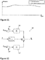
- Fig. 11 is a diagram showing a pressure profile and a logged pressure profile for the use in case of a level sensor fault on the basis of which several safety strategies are described. For a level sensor fault, the following applies.
- the level sensor (not shown) is transmitted from the reservoir 4 to the pump station or water reservoir supply pump arrangement 2 which typically are separated by several kilometres so that a sophisticated strategy for controlling the pump station or water reservoir supply pump arrangement 2 in the case of a level sensor fault is very important.
- the pump station or water reservoir supply pump arrangement 2 operates with the pressure values that have been provided to the system at the same time of the day the day before. This is done by setting up a profile of pressure values from the day before, or an average of the pressure from a number of days in the past. This is exemplified in this where the average pressure for each hour is logged, and used for the next day control in the case of a level sensor fault.
- Fig. 12 shows a control structure 10 for controlling the limits for the flow according to an embodiment of the present invention.
- the control structure 10 comprise two controllers 11 and 11' which here are embodied as PI controllers and which control the limits for the flow in order to ensure that the pressure is kept in accordance to the constraints p max and p min , with p max > p min .
- control variable control as represented in equation (2)
- the controller configuration shown in this figure 12 the controller 11 decreases the upper limit of the flow if the pressure is higher than the maximum pressure, and the controller 11' increases the lower limit of the flow if the pressure is lower than the minimum pressure requirement.
- the middle controller 11" is the level proportional controller described with respect to Fig. 1 .
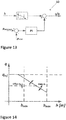
- Fig. 13 shows a further control structure 10 comprising an inlet pressure protection, which control structure 10 is available for both pressure control mode and flow control mode.
- control structure 10 is available for both pressure control mode and flow control mode.
- flow protection in case of flow control mode is described.
- inlet pressure protection With respect to inlet pressure protection, the following is noted. In many water supply systems, it is very important to protect the water reservoir at the inlet side of the pump station or water reservoir supply pump arrangement 2. Often the inlet pressure indicates the amount of water available in this reservoir 4. Therefore, an inlet pressure protection is designed for the pump controller 11. This protection has the same form as the protection function described above, except that it uses the inlet pressure measurement for the control, and its control architecture is shown in this figure.
- both a value for the gain G 1 and a value for the offset G 0 have to be identified automatically.
- the same approach as before is used. That is, as can be seen in Fig. 15 , the maximum value of the level obtained during a predefined time frame T , typically a day, is used. The only difference is that both the maximum and minimum levels during the time frame T are used.
- ⁇ and ⁇ are numbers between 0 and 1 which define the distance between the maximum acceptable level and the maximum level to be controlled, and similar for the minimum level.
- Fig. 15 which shows a level series identifying the maximum and minimum level for every day, the difference between the real maximum and minimum levels and the reference levels decreases each day by adjusting the gain and offset factors G 1 and G 0 .
- the algorithm can be used for both pressure and flow controlled pump stations or water reservoir supply pump arrangements 2.
- Fig. 16 is a diagram showing the control behaviour exemplified on the flow proportional curve for explaining safety control on the level.
- Fig. 17 is a diagram showing the level behaviour over a period of a couple of days, with an active control as described above in connection with Fig. 16 .
- the water level becomes lower than the minimum level h min , equation (17) becomes active and G 0 is updated.
- Fig. 18 is a schematic illustration of a system with elevated reservoir according to an embodiment of the present invention with a filling from multiple pump stations or water reservoir supply pump arrangements 2.
- the control of the individual pump station or water reservoir supply pump arrangement 2 should share the load (the flow) between the units in accordance with predefined settings.
- a water supply system 1 where two pump stations or water reservoir supply pump arrangements 2 supply water to the reservoir 4 is shown in this figure.
- the update laws for G 0 and G 1 are the same for all the pump stations or water reservoir supply pump arrangements 2 and a consensus algorithm ensures that the individual pump stations match the values.
- the consensus updates are performed with a higher sampling rate than the update law described by equations (12) and (13).
- the sampling time of the update law is typically 24 hours and for the consensus algorithm below 1 hour.
- the sampling time typically lies in the range of 10 - 60 minutes.
- U is the set of active units (the units that have communicated their values of G 0 and G 1 to the j th unit)
- is the number of units that have communicated their values
- ⁇ is a gain factor that controls the convergence of the agreement between the units.
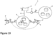
- Fig. 19 is a schematic illustration of a further water supply system 1 according to an embodiment of the present invention wherein filling is carried out by multiple pump stations or water reservoir supply pump arrangements 2.
- more than one pump station or water reservoir supply pump arrangements 2 share the flow between them in accordance with user defined rules. This is done by defining one of the pump stations or water reservoir supply pump arrangements 2 as the master station 2', and then letting this master pump station 2' communicate flow references to the remaining slave pump station 2" in accordance with the predefined rule as can be seen from this figure.
Landscapes
- Engineering & Computer Science (AREA)
- Life Sciences & Earth Sciences (AREA)
- Hydrology & Water Resources (AREA)
- Public Health (AREA)
- Water Supply & Treatment (AREA)
- Health & Medical Sciences (AREA)
- General Engineering & Computer Science (AREA)
- Physics & Mathematics (AREA)
- Mechanical Engineering (AREA)
- Structural Engineering (AREA)
- General Physics & Mathematics (AREA)
- Automation & Control Theory (AREA)
- Fluid Mechanics (AREA)
- Control Of Positive-Displacement Pumps (AREA)
- Control Of Non-Positive-Displacement Pumps (AREA)
Abstract
Description
- The invention relates to a method of controlling a water reservoir supply pump arrangement according to
claim 1, a method of controlling a plurality of water reservoir supply pump arrangements according toclaim 14, and a water reservoir supply pump arrangement according to claim 17. - Typically, municipal water supply systems utilize elevated reservoirs to set the pressure in the system and to keep backup water in case of an emergency available. In prior art, various setups of water supply systems comprising water tanks are known. For example, a rather typical example of such a setup widely employed in North and South America, comprises a tank which sets the pressure in the network, and serving as a disconnection reservoir between the system flow and the pump flow as shown in
Fig. 1 . This enables an on/off control of the pumps in the system. However, besides enabling an on/off control, the tank according to this configuration known from prior art serves as an emergency reservoir, as mentioned above. Moreover, the tank is able to act as a reactor for, for example, chorine injection, since all the water comprised in the system passes through this tank. - Another configuration known from prior art which is usually employed in Europe comprises a tank which has the same functions as described above, except for the function of acting as a reactor. There it is common that several consumers are connected to distribution water grid between the water tank and the booster pump as shown in
Fig. 2 . A further disadvantage of these configurations mostly used in Europe is that it is difficult to ensure the age of the water being below a predefined value. - In many cities, however, it is mandatory to have water reservoirs inside the buildings for purposes of firefighting. These water reservoirs are referred to as roof top tanks. The structure of a roof top tank system is similar to the system which is used in North and South America as described above, except for the tank being placed on top of the building.
- In all of the system configurations mentioned above, the pumps are typically controlled by an on/off controller that stops and starts the pumps in accordance with the water level in the tank.
- Moreover, it is known from prior art to run the pumps proportionally to the water level in the tank. In many large water supply systems, the pumps are started at different tank water levels, approximating a proportional pressure control.
- The systems described employ proportional control, as the pressure in the system is only changing rather slowly, thus, eliminating pressure shocks, and thereby also decreasing wear of the piping, valves, and pumps. Moreover, the proportional pressure control stabilizes the pressure in city areas, for example, when used with the systems described above for the European sector. This has the advantage that due to the stable system pressure, pipe bursts are prevented or at least reduced. In addition to the advantages with respect to the system pressure, changing from an on/off control to proportional control saves energy and thus, costs.
- However, proportional control is not widely used since it causes problems with adjusting the proportional factor so as to achieve the desired effect.
- For example, it is known in prior art to start pumps at different levels such that, for example, below a
level 1, one pump is running, below alevel 2, two pumps are running, and so on. - Further, from wastewater applications it is known to control the pump speed proportional to the water level.
- However, all approaches known from prior art are not able to automatically adjust the proportional factor so as to ensure a continuous flow.
- Another approach to this problem uses some kind of Model Predictive Control (MPC) which, however, is rather complicated and requires a sophisticated model of the system, thereby, involving high costs.
- Therefore, the present invention is based on the object to provide a method for controlling one or more water reservoir supply pump arrangement without compromising safety of the system.
- This problem is solved by a method for controlling a water reservoir supply pump arrangement having the features according to
claim 1, a method for controlling a plurality of water reservoir supply arrangements having the features according toclaim 14, as well as a water reservoir supply arrangement having the features according to claim 17. Preferred embodiments of the invention are specified in the respective dependent claims, the following description and in the drawings. - According to the present invention, a method of controlling a water reservoir supply pump arrangement is provided, wherein a set value p, q, v, n of the pump arrangement is determined based on an offset value pref, qref, nref, vref, G0 reduced by a component which is a function of the difference between the actual water level h and a predetermined water level href in the water reservoir, the difference being weighted automatically adjusted by a proportional gain factor G. According to the present invention, in addition to the on/off control, in the on-period, the pressure is allowed to vary with the level in the reservoir. This makes the system robust against sudden changes. Also robustness against control parameters design is ensured, since the tank level is controlled by means of a proportional controller with a fixed offset term. That is, stability is always ensured according to the inventive configuration. Namely, compared to a PI control, this is very important as the rather slow dynamics of the reservoir or tank makes it difficult to adjust the parameters of the PI controller properly. The use of a proportional controller ensures that the level in the reservoir varies during the day, and thereby ensures some change of water in the reservoir so as to maintain the water quality in the reservoir.
- Moreover, using a proportional control causes the pressure in the system to change only slowly, thereby, eliminating pressure shocks and decreasing wear of the piping, valves, and pumps.
- Another advantage of the inventive method is that the proportional pressure control stabilizes the pressure, for example, in city areas thereby avoiding pipe bursts. Finally, there are also advantages with respect to energy consumption.
- According to a preferred embodiment of the invention, the set value and the offset value are one of pump reference pressure, reference pump flow, reference pump speed, reference number of switched-on pumps in the supply pump arrangement.
- Moreover, preferably the predetermined water level is a minimum water level.
- The gain factor may be adjusted each time a predetermined water level, in particular a maximum water level, in the reservoir is reached and/or a predetermined time interval T has elapsed. Alternatively, the predetermined water level may be a minimum water level.
- Also, the gain factor and/or the offset value G1 may be adjusted such that the maximum water level measured over time is a fraction of the difference between a maximum and a minimum permissible water level.
- Further, it is preferable, if the gain factor is adjusted each time after a predetermined time interval T has elapsed such that


- Further, it is advantageous, if the pump arrangement is switched on when the actual water level is below a predetermined minimum level, and is switched off when the actual water level has reached a predetermined maximum water level.
- The set value preferably is the flow, and a maximum set flow preferably is decreased by a predetermined flow value if the pressure is higher than a predetermined maximum pressure value, and a minimum set flow preferably is increased by a predetermined flow value if the pressure is lower than a predetermined minimum pressure value.
- According to still a further preferred embodiment of the invention, the set value is pressure, and a maximum set pressure is decreased by a predetermined pressure value if the flow is higher than a predetermined maximum flow value, and a minimum set pressure is increased by a predetermined pressure value if the flow is lower than a predetermined minimum flow value.
- Moreover, the gain and the highest offset value may be adjusted such that variations of the water level over time utilize a predefined water level band, where the water level band lies between a maximum and a minimum allowed permissible water level.
- The set value may be one of pressure and flow, and the offset value may be gain, and wherein the proportional gain factor and the offset value may be adjusted each time a predetermined interval T has elapsed, the proportional gain factor and the offset value preferably being adjusted as


- G1,k+1 being the set value adjusted after the (k+1)th time interval,
- G1,k being the set value adjusted after the kth time interval,
- G0,k+1 being the offset value adjusted after the (k+1)th time interval,
- G0,k being the offset value adjusted after the kth time interval, and
- hhigh being the maximum level of the kth time interval,
- hlow being the minimum level of the kth time interval, and


- It is also preferable, if the set value is one of pressure and flow, and the offset value is gain, and wherein the proportional gain factor and the offset value are adjusted each time a predetermined interval T has elapsed, the proportional gain factor and the offset value being adjusted as


- Preferably, the set value is one of pressure and flow, and the offset value is gain, and wherein the offset value is updated each time a predetermined interval T has elapsed and if the water level drops below a minimum permissible level hmin, the offset value being adjusted as

- G0,t+1 being the offset value adjusted after the (t+1)th time interval,
- G0,t being the offset value adjusted after the tth time interval, and
- According to yet another preferred embodiments, all pump arrangements supply the same water reservoir, wherein the set value is flow, and wherein each set value is determined according to the method described before and the respective set values being scaled according to the following formula:

- The proportional gain factor and the offset value may be the same for all pump arrangements, and may be given by:


- Further, one of the pump arrangements may also comprise a plurality of slave pump arrangements and the respective sub-pump flows may be calculated according to

- According to the present invention, a water reservoir supply pump arrangement comprising at least one water pump and a control device for controlling the at least one pump according to the method described above is provided. The water reservoir supply arrangement according to the present invention offers a robust system with the various advantages described above.
- The invention is not limited to the described embodiments which can be modified in many ways. Preferred embodiments of the present invention will now be more particularly described, by way of example, with reference to the accompanying drawing, wherein:
- Fig. 1
- shows a schematic view for a setup of a water supply system according to prior art;
- Fig. 2
- shows a further schematic view for a setup of a water supply system according to prior art;
- Fig. 3
- shows a schematic view for a setup of a water supply system for buildings with roof top tanks;
- Fig. 4
- shows a proportional pressure curve for a water reservoir supply pump arrangement according to an embodiment of the present invention;
- Fig.5
- shows a schematic illustration for the division between on/off control mode and continuous level control mode for controlling a pump according to an embodiment of the present invention;
- Fig. 6
- shows a schematic view for a setup which is controlled according to an embodiment of the method according to the present invention;
- Fig. 7
- shows a further schematic view for a setup which is controlled to a further embodiment of the method according to the present invention;
- Fig. 8
- is a diagram showing a level series for identifying a maximum level on a daily basis;
- Fig.9
- shows a schematic view for a setup which is controlled according to still a further embodiment of the method according to the present invention;
- Fig. 10
- shows a schematic view for a setup which is controlled according to another embodiment of the method according to the present invention;
- Fig. 11
- is a diagram showing a pressure profile and a logged pressure profile for the use in case of a level sensor fault;
- Fig. 12
- shows a control structure for controlling the limits for the flow according to an embodiment of the present invention;
- Fig. 13
- shows a further control structure comprising an inlet pressure protection;
- Fig. 14
- is a diagram showing a proportional level curve, where a predefined water level band is utilized;
- Fig. 15
- shows a further level series identifying the maximum and minimum levels on a daily basis;
- Fig. 16
- is a diagram showing the control behaviour exemplified on the flow proportional curve;
- Fig. 17
- is a diagram showing the level behaviour over a period of a couple of days, where the actual water level has fallen below the minimum permissible water level threshold;
- Fig. 18
- is a schematic illustration of a system with elevated reservoir according to an embodiment of the present invention; and
- Fig. 19
- is a schematic illustration of a water supply system according to an embodiment of the present invention.
-
Fig. 1 shows a schematic view for a setup for awater supply system 1 according to prior art as it is typically used in America and Asia. Thewater supply system 1 comprises a water reservoirsupply pump arrangement 2 with apump 3 and a tank orreservoir 4 for supplying water to a plurality ofhouses 5. Thereservoir 3, here, controls the pressure in the network connected bypipes 6 and serves as a disconnection reservoir between the end user flow qu and the pump flow qp. This enables an on/off control of thepump 3 or a plurality of pumps, whereby the water level h inwater reservoir 4 is controlled by on/off controllers which start thepumps 3 when a low-level threshold is reached and stops the pumps when a high-level threshold is reached. Besides enabling on/of control, thereservoir 4 serves as an emergency reservoir. Moreover, thereservoir 4 may also function as a reactor for, for example, chlorine injection, since all the water in thewater supply system 1 passes through thereservoir 4. -
Fig. 2 shows a further schematic arrangement of awater supply system 1 according to prior art which commonly is used in Europe. The configuration shown basically corresponds to the one illustrated inFig. 1 . However, here thereservoir 4 is not able to function as reactor. A further disadvantage with this configuration is that it is difficult to ensure the age of the water is below a predefined value. -
Fig. 3 shows a schematic arrangement of awater supply system 1 for abuilding 7 with a roof top tank orreservoir 4 which are employed in cities in which it is mandatory to have water reservoirs inside thebuilding 7 for firefighting. Thewater supply system 1 shown here also is similar to the one shown inFig. 1 , except that the tank orreservoir 4 is placed on thetop 8 of thebuilding 7. - In all
water supply systems 1 described above, a controller controls thepump 3 or a plurality of pumps so as to stop and start thepump 3 or pumps in accordance with a water level h in the tank orreservoir 4. It is noted that in many largewater supply systems 1, thepumps 3 are started at different water levels h which procedure approximates a proportional pressure control. However, according to prior art applications, it is not possible to adjust the proportional factor automatically so as to ensure a continuous flow. -
Fig. 4 shows a proportional pressure curve for a water reservoirsupply pump arrangement 2 according to an embodiment of the present invention. Here, a pressure set-point pset for a controller of a pump station or water reservoirsupply pump arrangement 2 is a function of the water level h in thereservoir 4. In the diagram ofFig. 4 , pref indicates the maximum pressure set point for the pumping station controller, and the tank or reservoir water level h is controlled between a minimum water level setting hmin of thereservoir 4 and a maximum water level setting hmax of thereservoir 4 by using a proportional controller with a fixed offset term so that the water level h stays below pref. The reason for this is that it ensures robustness against the control parameters design. That is, in addition to the other advantages already listed above, stability is always ensured in thewater supply system 1. - In the on-periods, the pump station water reservoir
supply pump arrangement 2 controls the pressure in accordance with the level h following the relation equation (1)
supply pump arrangement 2, pref being the pressure reference of the pump station water reservoirsupply pump arrangement 2 when running as an on/off controller, and G being the proportional factor. Further, h is the actual level in the tank orreservoir 4, and hmin is the minimum permissible level threshold set by the user. The effect of this control is illustrated inFig. 4 . According to this approach, the pressure is used as a reference value or pump station reference. Instead, the flow could be used just as well, in which case the proportional control would be represented by equation (2):
- In the case of a water reservoir
supply pump arrangement 2, which is controlled by a speed reference, the proportional control would be represented by equation (3):
- Finally, in the case where the water reservoir
supply pump arrangement 2 comprises fixed speed pumps 3, the number of runningpumps 3 can be controlled proportional to the level h. Let v denote the number ofactive pumps 3, then the proportional control would be represented by equation (4):
- On the basis of
Fig. 5 showing a schematic illustration for the division between on/offcontrol mode 12 and continuouslevel control mode 13 for controlling apump 3 according to an embodiment of the present invention, the adaptive adjustment of the gain factor G is explained. The adjustment of the gain factor G in the previous described level control strategy is in this approach adaptive. The adjustment strategy is divided into two levels following the division of the level control strategy. - The main control strategy is on/off
control 12. This control ensures that the level h never exceeds the maximum level setting and never decrease below the minimum level setting. This is done by switching the complete pump station or water reservoirsupply pump arrangement 2 on and off based on the level settings. When the pump station or water reservoirsupply pump arrangement 2 is switched on, thecontinuous level control 13 adjusts the pump pressure and flow depending on the choice of control. This is done according to the control described in equations (1) to (4). The gain is adjusted both in the on/off control and in the continuous control and areference output 14 is obtained. In the following, first the adjustment in the on/offcontrol mode 12 is described followed by the adjustment in thecontinuous control mode 13. -
Fig. 6 shows a schematic view for a setup which is controlled according to an embodiment of the method according to the present invention, wherein astate machine 9 controls the level h and adjusts the gain factor G so as to ensure continuous operation of the pump station or water reservoirsupply pump arrangement 2. - As described above, the problem with the use of a proportional tank filling control is to choose a good value for the gain factor G. Here, this problem is solved by adjusting the gain each time the maximum level is reached as this is an indication that the pressure is too high to obtain continuous pump operation. The
state machine 9 illustrated inFig. 6 acts on the level, starts and stops thepump 3 of the pump station or water reservoirsupply pump arrangement 2. The state machine adjusts the gain factor G after eachpump 3 is switched off, and at predefined time instants to obtain continuous pump operation. -
Fig. 7 shows a further schematic view for a setup which is controlled to a further embodiment of the method according to the present invention. Here, thestate machine 9 identifies the minimum and maximum control level and adjusts the gain factor G according to the on/off level control signal. This applies for cases in which thewater supply system 1 is equipped with a level controller that sends an on/off signal to the pump controller. In these cases this on/off signal can be used for identifying the minimum and maximum level and to adjust the gain factor G, as is done by thestate machine 9 shown here. -
Fig. 8 is a diagram for explaining the adjustment in the continuous control and showing a level series for identifying a maximum level on a daily basis. Here, the value of the maximum level decreases by increasing the gain factor G until the maximum level is below the value h*high - When the
pump 3 is running continuously the gain G is adjusted such that the maximum valve of h is around 80% of the difference between the maximum and minimum level threshold (hmax and hmin). This is done by first identifying the highest level obtained over a given period according to equation (5):
- When the maximum level over the period T is known then G is adjusted according to the following equation (6) once in each time period T:


-
Fig. 9 shows a schematic view for a setup which is controlled according to still a further embodiment of the method according to the present invention. Here, a procedure or strategy for pump station control with forced water change in the tank orreservoir 4 and the water quality features are explained. - The age of the water in the
reservoir 4 is a very important parameter for the quality of the water. To ensure the water quality, the average stay time of the water in thereservoir 4 must be limited, and thereservoir 4 has to be clean. With the control approach described in connection with thisfigure 9 , the natural stay time of the water will increase in applications with a structure similar to thewater supply system 1 shown inFig. 2 . Here, the water quality problem with the following two features. - In order to ensure water quality, an emptying procedure is initiated at predefined times, typically once a day or once a week. The
state event machine 9 shown in this figure controls the emptying procedure. At the empty state, the pumping station or water reservoirsupply pump arrangement 2 controls the pressure or flow according to a predefined pressure or flow set point that is low enough to empty thereservoir 4. Alternatively, thepumps 3 of the pump station or water reservoirsupply pump arrangement 2 stop. -
Fig. 10 shows a schematic view for a further setup which is controlled according to another embodiment of the method according to the present invention. Here, a strategy for pump station control for cleaning the tank orreservoir 4 will be explained, wherein "cleaning" means that thereservoir 4 is filled to its maximum ensuring that thewhole reservoir 4 is flushed. Thestate event machine 9 illustrated here carries out such a cleaning procedure. The cleaning Level in the figure is the level that defines the top of the tank orreservoir 4 just before water flows over. Commonly, the cleaning procedure is run as the reservoir is already filled to its maximum, thereby ensuring the best possible change of the water. -
Fig. 11 is a diagram showing a pressure profile and a logged pressure profile for the use in case of a level sensor fault on the basis of which several safety strategies are described. For a level sensor fault, the following applies. - The level sensor (not shown) is transmitted from the
reservoir 4 to the pump station or water reservoirsupply pump arrangement 2 which typically are separated by several kilometres so that a sophisticated strategy for controlling the pump station or water reservoirsupply pump arrangement 2 in the case of a level sensor fault is very important. When a level sensor fault appears, the pump station or water reservoirsupply pump arrangement 2 operates with the pressure values that have been provided to the system at the same time of the day the day before. This is done by setting up a profile of pressure values from the day before, or an average of the pressure from a number of days in the past. This is exemplified in this where the average pressure for each hour is logged, and used for the next day control in the case of a level sensor fault. -
Fig. 12 shows acontrol structure 10 for controlling the limits for the flow according to an embodiment of the present invention. Thecontrol structure 10 comprise twocontrollers 11 and 11' which here are embodied as PI controllers and which control the limits for the flow in order to ensure that the pressure is kept in accordance to the constraints pmax and pmin, with pmax > pmin. - In the case where the flow q is chosen as the control variable (control as represented in equation (2) there is a risk of the pressure becoming too high or too low for the
water supply system 1, if the connection to the tank orreservoir 4 is closed (for example due to cleaning). To avoid the pressure being too high or too low, variable constraints are set on the flow. This is accomplished by the controller configuration shown in thisfigure 12 . In this configuration, thecontroller 11 decreases the upper limit of the flow if the pressure is higher than the maximum pressure, and the controller 11' increases the lower limit of the flow if the pressure is lower than the minimum pressure requirement. Themiddle controller 11" is the level proportional controller described with respect toFig. 1 . -
Fig. 13 shows afurther control structure 10 comprising an inlet pressure protection, which controlstructure 10 is available for both pressure control mode and flow control mode. In the following, flow protection in case of flow control mode is described. - In the case where the pressure p is chosen as the control variable (control procedure represented by equation (1), there is a risk that the flow becomes too high or too low for the
water supply system 1. In order to avoid the flow being too high or too low, variable constraints are set on the pressure. This is accomplished in a similar way as it was described with respect toFig. 12 as to pressure protection. Especially, high flow protection is an important feature as this can be part of a protection scheme that protects the water resource from which the pump station or water reservoirsupply pump arrangement 2 is supplied. - With respect to inlet pressure protection, the following is noted. In many water supply systems, it is very important to protect the water reservoir at the inlet side of the pump station or water reservoir
supply pump arrangement 2. Often the inlet pressure indicates the amount of water available in thisreservoir 4. Therefore, an inlet pressure protection is designed for thepump controller 11. This protection has the same form as the protection function described above, except that it uses the inlet pressure measurement for the control, and its control architecture is shown in this figure. -
Fig. 14 is a diagram showing a proportional level curve in which both the offset and the gain terms are adjusted. If the largest possible variations in the level and thereby the largest possible exchange of water during the day should be ensured, both the gain G1 and the offset term qmax = G 0 must be adjusted, wherein the adjustment of both the gain and the offset is illustrated inFig. 14 . With respect to the flow control case, the expression proportional level curve is given by equation (7):

- In this case, both a value for the gain G1 and a value for the offset G 0 have to be identified automatically. The same approach as before is used. That is, as can be seen in
Fig. 15 , the maximum value of the level obtained during a predefined time frame T, typically a day, is used. The only difference is that both the maximum and minimum levels during the time frame T are used. These values are obtained by equations (8) and (9):

- References for the maximum and minimum levels can be defined by equations (10) and (11):


- where α and β are numbers between 0 and 1 which define the distance between the maximum acceptable level and the maximum level to be controlled, and similar for the minimum level. As can be seen in
Fig. 15 which shows a level series identifying the maximum and minimum level for every day, the difference between the real maximum and minimum levels and the reference levels decreases each day by adjusting the gain and offset factors G1 and G0. - The update laws for the gain and offset terms are represented by the following equations (12) and (13):


- To obtain a better convergence behaviour, it may be beneficial to scale the update law for the offset term by the estimated gain according to equation (14):

- As in the previous case, the algorithm can be used for both pressure and flow controlled pump stations or water reservoir
supply pump arrangements 2. In the case of a pressure controlled pumping station, the proportional level control can be defined by equation (15):
supply pump arrangement 2, just with other numerical values for the gain terms. -
Fig. 16 is a diagram showing the control behaviour exemplified on the flow proportional curve for explaining safety control on the level. With the approach where both G 0 and G1 are adjusted to fulfil requirements on both the average level and the variation of the level in thereservoir 4, it is no longer possible to guarantee that the output pressure or flow is at its maximum when the minimum level is reached. This can cause the level to decrease below the acceptable minimum level in case of changes in the demand. To solve this problem the flow/pressure set point is increased with the level by adjusting the offset term G 0 . This is done each time a predetermined time period T has elapsed in accordance with the following update law represented by equation (16):
- This implies that each time the level becomes lower than the minimum level hmin, the following algorithm according to equation (17) is running

Fig. 16 for a case of levels below the minimum level. -
Fig. 17 is a diagram showing the level behaviour over a period of a couple of days, with an active control as described above in connection withFig. 16 . Atday 2 the water level becomes lower than the minimum level hmin, equation (17) becomes active and G 0 is updated. -
Fig. 18 is a schematic illustration of a system with elevated reservoir according to an embodiment of the present invention with a filling from multiple pump stations or water reservoirsupply pump arrangements 2. In the case where thereservoir 4 is supplied from multiple sources, the control of the individual pump station or water reservoirsupply pump arrangement 2 should share the load (the flow) between the units in accordance with predefined settings. Awater supply system 1 where two pump stations or water reservoirsupply pump arrangements 2 supply water to thereservoir 4 is shown in this figure. Here, each of thepumps 3 runs the same control loop represented by equation (18):
- Here, s is a scaling coefficient that adjusts the amount of water delivered by the different pumping stations or water reservoir
supply pump arrangements 2. That is, if si = sj then the ith and jth pump station or water reservoirsupply pump arrangement 2 delivers the same flow, and if si ≠ sj , then the ith and jth pump station or water reservoirsupply pump arrangement 2 delivers flow accordingly. In this embodiment, si i = 1, ···,n is chosen by the users. - The update laws for G 0 and G 1 are the same for all the pump stations or water reservoir
supply pump arrangements 2 and a consensus algorithm ensures that the individual pump stations match the values. The consensus updates are performed with a higher sampling rate than the update law described by equations (12) and (13). The sampling time of the update law is typically 24 hours and for the consensus algorithm below 1 hour. The consensus updates are controlled by the following update law described by equations (19) and (20):

-
Fig. 19 is a schematic illustration of a furtherwater supply system 1 according to an embodiment of the present invention wherein filling is carried out by multiple pump stations or water reservoirsupply pump arrangements 2. In the case shown here, more than one pump station or water reservoirsupply pump arrangements 2 share the flow between them in accordance with user defined rules. This is done by defining one of the pump stations or water reservoirsupply pump arrangements 2 as the master station 2', and then letting this master pump station 2' communicate flow references to the remainingslave pump station 2" in accordance with the predefined rule as can be seen from this figure. - Thereby, the
slave pump station 2" is controlled to a reference flow which is calculated based on the flow of the master pump station 2' according to equation (21):
pump stations 2', 2". - Finally, some alternative applications are mentioned. The proposed control approach can also be used for filling large reservoirs such as big ponds for raw water for water supply. Also empting reservoirs can be accomplished by a control that controls the flow proportional to the level. In this case, the flow should be controlled in accordance to the level following the rule represented by equation (22):

- Besides this, the approach is similar to the embodiments described above.
- 1 water supply system
2, 2', 2" water reservoir supply pump arrangement / pump station
3 pump
4 reservoir / tank
5 house
6 pipe
7 building
8 top of the building
9 state machine
10 control structure
11, 11' controller
12 on/off control mode
13 continuous control mode
14 reference output
h water level in reservoir / tank
hmin minimum level setting of reservoir / tank
hmax maximum level setting of reservoir / tank.
G gain factor
p pressure
pinlet pressure at the inlet
pmax maximum pressure
pmin minimum pressure
pp, pp1, pp2 outlet pump pressure
pset pressure set point for pump station controller
pref maximum pressure set point for the pump station controller
q flow
qp, qp1, qp2 outlet pump flow
qref maximum flow set point for the pump station
qu, qu1, qu2 end user flow
qset flow set point for the pump station controller
qmax maximum allowed flow from the pump station
nset speed set point of the pump station controller
nmax maximum speed of the pump station
vset number of running pumps in the pump station
vmax number of pumps of the pump station
t, k integer number of sampling times
T period where the level is analysed to find the highest level reached
hhigh highest level reached in the time interval T

hlow lowest level reached in the time interval T

α fraction between the maximum level hmax and the minimum level hmin the level should reach in the period T
β another fraction
K adjustment factor for adjusting the G when the pumping station is operating continuously
Si flow scaling of the ith pump station
κ gain factor that controls the consensus algorithm that controls the behaviour between the pump stations
Claims (17)
- Method of controlling a water reservoir supply pump arrangement (2), wherein a set value (p, q, v, n) of the pump arrangement (2) is determined based on an offset value (pref, qref, nref, vref, Go) reduced by a component which is a function of the difference between the actual water level (h) and a predetermined water level (href) in a water reservoir (4), the difference being weighted by an automatically adjusted proportional gain factor (G).
- The method according to claim 1, wherein the set value and the offset value are one of pump reference pressure, reference pump flow, reference pump speed, reference number of switched-on pumps in the water reservoir supply pump arrangement (2).
- The method according to any one of the preceding claims, wherein the predetermined water level is a minimum water level.
- The method according to any one of the preceding claims, wherein the gain factor is adjusted each time a predetermined water level, in particular a maximum water level, in the reservoir (4) is reached and/or a predetermined time interval (T) has elapsed.
- The method according to any one of the preceding claims, wherein the gain factor (G1) and/or the offset value are adjusted such that the maximum water level measured over time is a fraction of the difference between a maximum and a minimum permissible water level.
- The method according to claim 5, wherein the gain factor is adjusted each time after a predetermined time interval (T) has elapsed such that


- The method according to any one of the preceding claims, wherein the water reservoir supply pump arrangement (2) is switched on when the actual water level is below a predetermined minimum level and is switched off when the actual water level has reached a predetermined maximum water level.
- The method according to any one of the preceding claims, wherein the set value is the flow, and a maximum set flow is decreased by a predetermined flow value if the pressure is higher than a predetermined maximum pressure value, and a minimum set flow is increased by a predetermined flow value as long as the pressure is lower than a predetermined minimum pressure value.
- The method according to any one of the claims 1 to 7, wherein the set value is pressure, and a maximum set pressure is decreased by a predetermined pressure value if the flow is higher than a predetermined maximum flow value, and a minimum set pressure is increased by a predetermined pressure value if the flow is lower than a predetermined minimum flow value.
- The method according to any one of the preceding claims, wherein the gain (G1) and the offset value (G0) are adjusted such that variations of the water level over the time utilize a predefined water level band, where the water level band lies between a maximum and a minimum permissible water level.
- The method according to claim 1, wherein the set value is one of pressure and flow, and the offset value is gain, and wherein the proportional gain factor and the offset value are adjusted each time a predetermined interval (T) has lapsed, the proportional gain factor and the offset value being adjusted as

 G1,k+1 being the set value adjusted after the (k+1)th time interval,G1,kbeing the set value adjusted after the kth time interval,G0,k+1 being the offset value adjusted after the (k+1)th time interval,G0,k being the offset value adjusted after the kth time interval,
andhhigh being the maximum level of the kth time interval,hlow being the minimum level of the kth time interval,
and

- The method according to claim 1, wherein the set value is one of pressure and flow, and the offset value is gain, and wherein the proportional gain factor and the offset value are adjusted each time a predetermined interval (T) has elapsed, the proportional gain factor and the offset value being adjusted as

 G1,k+1 being the set value adjusted after the (k+1)th time interval,G1,k being the set value adjusted after the kth time interval,G0,k+1 being the offset value adjusted after the (k+1)th time interval,G0,k being the offset value adjusted after the kth time interval, andhhigh being the maximum level of the kth time interval,hlow being the minimum level of the kth time interval, and

- The method according to claim 1, wherein the set value is one of pressure and flow, and the offset value is gain, and wherein the the offset value is updated each time a predetermined interval (T) has elapsed and if the water level has dropped below the minimum permissible level (hmin), the offset value being adjusted as
 G0,t+1 being the offset value adjusted after the (t+1)th time interval,G0,t being the offset value adjusted after the tth time interval, andK2 being a predetermined constant >0
 - Method of controlling a plurality of water reservoir supply pump arrangements (2), all pump arrangements (2) supplying the same water reservoir (4), wherein the set value is flow, and wherein each set value is determined according to the method of any one of the preceding claims, and the respective set values being scaled according to the following formula:

- The method according to any one of the preceding claims, wherein the proportional gain factor and the offset value are the same for all pump arrangements (2), and given by:


- The method according to any one of the preceding claims, wherein one of the pump arrangements (2) comprise a plurality of slave pump arrangements and the respective sub-pump flows are calculated according to

- Water reservoir supply pump arrangement (2) comprising at least one water pump (3) and a control device (11) for controlling the at least one pump (3) according to the method according to any one of claims 1 to 16.
Priority Applications (4)
| Application Number | Priority Date | Filing Date | Title |
|---|---|---|---|
| EP16200618.3A EP3327292B1 (en) | 2016-11-25 | 2016-11-25 | Method of controlling a water reservoir supply pump arrangement and water reservoir supply pump arrangement |
| US15/820,964 US11060266B2 (en) | 2016-11-25 | 2017-11-22 | Method of controlling a water reservoir supply pump arrangement and water reservoir supply pump arrangement |
| RU2017140784A RU2689561C2 (en) | 2016-11-25 | 2017-11-23 | Method of controlling water tank pumping assembly layout and water reservoir pumping assembly delivery arrangement |
| CN201711203755.1A CN108104208B (en) | 2016-11-25 | 2017-11-27 | Method for controlling a reservoir water supply pump device and reservoir water supply pump device |
Applications Claiming Priority (1)
| Application Number | Priority Date | Filing Date | Title |
|---|---|---|---|
| EP16200618.3A EP3327292B1 (en) | 2016-11-25 | 2016-11-25 | Method of controlling a water reservoir supply pump arrangement and water reservoir supply pump arrangement |
Publications (2)
| Publication Number | Publication Date |
|---|---|
| EP3327292A1 true EP3327292A1 (en) | 2018-05-30 |
| EP3327292B1 EP3327292B1 (en) | 2020-09-16 |
Family
ID=57406101
Family Applications (1)
| Application Number | Title | Priority Date | Filing Date |
|---|---|---|---|
| EP16200618.3A Active EP3327292B1 (en) | 2016-11-25 | 2016-11-25 | Method of controlling a water reservoir supply pump arrangement and water reservoir supply pump arrangement |
Country Status (4)
| Country | Link |
|---|---|
| US (1) | US11060266B2 (en) |
| EP (1) | EP3327292B1 (en) |
| CN (1) | CN108104208B (en) |
| RU (1) | RU2689561C2 (en) |
Cited By (2)
| Publication number | Priority date | Publication date | Assignee | Title |
|---|---|---|---|---|
| WO2021019204A1 (en) * | 2019-07-30 | 2021-02-04 | Hydrosave Limited | Apparatus and method for maintenance of a water supply |
| CN116201207A (en) * | 2023-03-22 | 2023-06-02 | 贵州十懿建筑工程咨询服务有限公司 | Water pump water supply system |
Families Citing this family (6)
| Publication number | Priority date | Publication date | Assignee | Title |
|---|---|---|---|---|
| EP3588234B1 (en) * | 2018-06-21 | 2021-03-17 | Grundfos Holding A/S | Control system and method for controlling a water supply from at least two separate input lines into a sector of a water supply network |
| CN109113131B (en) * | 2018-10-12 | 2024-01-30 | 宁波巨神制泵实业有限公司 | Automatic coupling intelligent integrated cable-stayed pump station |
| CN109597436A (en) * | 2018-10-25 | 2019-04-09 | 成都市自来水有限责任公司 | A kind of V-type filter tank perseverance method for controlling water level |
| CN109736388A (en) * | 2019-02-27 | 2019-05-10 | 深圳市鸿效节能股份有限公司 | Supplier with secondary pressurizer and method |
| CN111910588A (en) * | 2020-08-11 | 2020-11-10 | 安徽省万豪水坝节能技术有限公司 | Intelligent water conservancy hydraulic dam detection control system and method |
| CN112663721B (en) * | 2020-12-15 | 2021-07-23 | 重庆昕晟环保科技有限公司 | Intelligent water supply method of secondary water supply tank |
Citations (5)
| Publication number | Priority date | Publication date | Assignee | Title |
|---|---|---|---|---|
| US4265263A (en) * | 1979-08-28 | 1981-05-05 | Phillips Petroleum Company | Non-linear level controller |
| DE4222867A1 (en) * | 1992-07-11 | 1994-01-13 | Johann Binder | Industrial water conduction system - has at least one conveying pump driven by controller |
| GB2294748A (en) * | 1994-12-23 | 1996-05-08 | Boilerhouse Services Ltd | Improvements in and relating to the regulation of the level of water in a pressurised boiler |
| US20120170702A1 (en) * | 2010-12-30 | 2012-07-05 | Kepco Engineering & Construction Company | System of controlling steam generator level during main feed-water control valve transfer for nuclear power plant |
| US20140271235A1 (en) * | 2013-03-14 | 2014-09-18 | Regal Beloit America, Inc. | Dynamic speed control for pump motor |
Family Cites Families (10)
| Publication number | Priority date | Publication date | Assignee | Title |
|---|---|---|---|---|
| US5197859A (en) * | 1970-11-29 | 1993-03-30 | Siff Elliott J | Well pump system |
| JPS5351386A (en) * | 1976-10-20 | 1978-05-10 | Hitachi Ltd | Operation of fluid transportation system |
| SU1551827A1 (en) | 1988-06-07 | 1990-03-23 | Московский гидромелиоративный институт | Method of controlling a pumping station |
| JP3800713B2 (en) * | 1996-09-12 | 2006-07-26 | 株式会社明電舎 | Water distribution facility control equipment |
| US6422263B1 (en) * | 2000-09-05 | 2002-07-23 | Guy Kevin Spicer | Nested and cascaded variable bias feedfoward and feedback flow and level control system |
| US8019479B2 (en) * | 2004-08-26 | 2011-09-13 | Pentair Water Pool And Spa, Inc. | Control algorithm of variable speed pumping system |
| US7931041B2 (en) * | 2007-12-19 | 2011-04-26 | General Electric Company | System and method for controlling liquid level in a vessel |
| JP5191361B2 (en) * | 2008-11-21 | 2013-05-08 | 株式会社日立製作所 | Liquid level control system. |
| US8910649B2 (en) * | 2009-07-15 | 2014-12-16 | Jainendra Kumar Singh | Readily cleanable water storage system and method |
| CN106707753A (en) | 2016-12-25 | 2017-05-24 | 北京工业大学 | Pump linear motor adaptive control method |
-
2016
- 2016-11-25 EP EP16200618.3A patent/EP3327292B1/en active Active
-
2017
- 2017-11-22 US US15/820,964 patent/US11060266B2/en active Active
- 2017-11-23 RU RU2017140784A patent/RU2689561C2/en active
- 2017-11-27 CN CN201711203755.1A patent/CN108104208B/en active Active
Patent Citations (5)
| Publication number | Priority date | Publication date | Assignee | Title |
|---|---|---|---|---|
| US4265263A (en) * | 1979-08-28 | 1981-05-05 | Phillips Petroleum Company | Non-linear level controller |
| DE4222867A1 (en) * | 1992-07-11 | 1994-01-13 | Johann Binder | Industrial water conduction system - has at least one conveying pump driven by controller |
| GB2294748A (en) * | 1994-12-23 | 1996-05-08 | Boilerhouse Services Ltd | Improvements in and relating to the regulation of the level of water in a pressurised boiler |
| US20120170702A1 (en) * | 2010-12-30 | 2012-07-05 | Kepco Engineering & Construction Company | System of controlling steam generator level during main feed-water control valve transfer for nuclear power plant |
| US20140271235A1 (en) * | 2013-03-14 | 2014-09-18 | Regal Beloit America, Inc. | Dynamic speed control for pump motor |
Cited By (3)
| Publication number | Priority date | Publication date | Assignee | Title |
|---|---|---|---|---|
| WO2021019204A1 (en) * | 2019-07-30 | 2021-02-04 | Hydrosave Limited | Apparatus and method for maintenance of a water supply |
| GB2600874A (en) * | 2019-07-30 | 2022-05-11 | Hydrosave Uk Ltd | Apparatus and method for maintenance of a water supply |
| CN116201207A (en) * | 2023-03-22 | 2023-06-02 | 贵州十懿建筑工程咨询服务有限公司 | Water pump water supply system |
Also Published As
| Publication number | Publication date |
|---|---|
| CN108104208B (en) | 2020-12-18 |
| US11060266B2 (en) | 2021-07-13 |
| CN108104208A (en) | 2018-06-01 |
| RU2017140784A3 (en) | 2019-05-23 |
| EP3327292B1 (en) | 2020-09-16 |
| RU2017140784A (en) | 2019-05-23 |
| US20180148909A1 (en) | 2018-05-31 |
| RU2689561C2 (en) | 2019-05-28 |
Similar Documents
| Publication | Publication Date | Title |
|---|---|---|
| EP3327292B1 (en) | Method of controlling a water reservoir supply pump arrangement and water reservoir supply pump arrangement | |
| US9493931B2 (en) | Mains water supply processing | |
| US6325093B1 (en) | Water distributing installation controllers | |
| CN101901014B (en) | Method for controlling forecast pressure regulation in air compression stations | |
| JP5010504B2 (en) | Water distribution pressure optimum control device | |
| CN110632962B (en) | Control system and method for controlling water supply from at least two separate input lines to a water supply network sector | |
| CN102341352A (en) | Regulated supply of treated water to regional water networks | |
| US11326591B2 (en) | Pressure boosting device | |
| CN105756140A (en) | Municipal water tank regulating and storing system and regulating and storing method thereof | |
| US20180045168A1 (en) | Control system for flow of turbined water from a plurality of hydroelectric plants | |
| CN107544569B (en) | Control method for keeping constant liquid level of filtering state of V-shaped filter tank | |
| CN112624389A (en) | Water purification system capable of changing pulse wastewater discharge and control method | |
| JP2012160170A (en) | Water supply control method of water purification facility | |
| Clemmens | Canal automation | |
| AU2008234705A1 (en) | Improvements in and relating to sewage pumping | |
| JP2019000804A (en) | Membrane separator | |
| CN107905345B (en) | A kind of sewage treatment plant's bilge well water discharge control method | |
| CN121047324B (en) | A zoned multi-stage series pressurized conveying system and a balance control platform | |
| JPS5935043B2 (en) | Water volume smoothing system for water distribution facilities | |
| JP2752147B2 (en) | Water distribution network controller | |
| CN117341924A (en) | Intelligent marine organism prevention system for semi-submersible platform or bottoming platform | |
| RU2728770C2 (en) | Control method of operating mode of booster pump station | |
| JP2001241066A (en) | Water distribution control method, slave station device and water supply management system | |
| CN121872495A (en) | A reverse osmosis concentrate nanofiltration series treatment system and method | |
| JPS5920123B2 (en) | Sewage pump control system for sewage treatment plants |
Legal Events
| Date | Code | Title | Description |
|---|---|---|---|
| PUAI | Public reference made under article 153(3) epc to a published international application that has entered the european phase |
Free format text: ORIGINAL CODE: 0009012 |
|
| STAA | Information on the status of an ep patent application or granted ep patent |
Free format text: STATUS: THE APPLICATION HAS BEEN PUBLISHED |
|
| AK | Designated contracting states |
Kind code of ref document: A1 Designated state(s): AL AT BE BG CH CY CZ DE DK EE ES FI FR GB GR HR HU IE IS IT LI LT LU LV MC MK MT NL NO PL PT RO RS SE SI SK SM TR |
|
| AX | Request for extension of the european patent |
Extension state: BA ME |
|
| STAA | Information on the status of an ep patent application or granted ep patent |
Free format text: STATUS: REQUEST FOR EXAMINATION WAS MADE |
|
| 17P | Request for examination filed |
Effective date: 20181130 |
|
| RBV | Designated contracting states (corrected) |
Designated state(s): AL AT BE BG CH CY CZ DE DK EE ES FI FR GB GR HR HU IE IS IT LI LT LU LV MC MK MT NL NO PL PT RO RS SE SI SK SM TR |
|
| GRAP | Despatch of communication of intention to grant a patent |
Free format text: ORIGINAL CODE: EPIDOSNIGR1 |
|
| STAA | Information on the status of an ep patent application or granted ep patent |
Free format text: STATUS: GRANT OF PATENT IS INTENDED |
|
| RIC1 | Information provided on ipc code assigned before grant |
Ipc: E03B 7/02 20060101ALI20200401BHEP Ipc: E03B 5/00 20060101ALI20200401BHEP Ipc: E03B 11/10 20060101ALI20200401BHEP Ipc: F04D 15/00 20060101AFI20200401BHEP Ipc: G05D 9/12 20060101ALI20200401BHEP Ipc: E03B 7/07 20060101ALI20200401BHEP |
|
| INTG | Intention to grant announced |
Effective date: 20200424 |
|
| GRAS | Grant fee paid |
Free format text: ORIGINAL CODE: EPIDOSNIGR3 |
|
| GRAA | (expected) grant |
Free format text: ORIGINAL CODE: 0009210 |
|
| STAA | Information on the status of an ep patent application or granted ep patent |
Free format text: STATUS: THE PATENT HAS BEEN GRANTED |
|
| AK | Designated contracting states |
Kind code of ref document: B1 Designated state(s): AL AT BE BG CH CY CZ DE DK EE ES FI FR GB GR HR HU IE IS IT LI LT LU LV MC MK MT NL NO PL PT RO RS SE SI SK SM TR |
|
| REG | Reference to a national code |
Ref country code: GB Ref legal event code: FG4D |
|
| REG | Reference to a national code |
Ref country code: CH Ref legal event code: EP |
|
| REG | Reference to a national code |
Ref country code: DE Ref legal event code: R096 Ref document number: 602016044024 Country of ref document: DE |
|
| REG | Reference to a national code |
Ref country code: IE Ref legal event code: FG4D |
|
| REG | Reference to a national code |
Ref country code: AT Ref legal event code: REF Ref document number: 1314382 Country of ref document: AT Kind code of ref document: T Effective date: 20201015 |
|
| PG25 | Lapsed in a contracting state [announced via postgrant information from national office to epo] |
Ref country code: HR Free format text: LAPSE BECAUSE OF FAILURE TO SUBMIT A TRANSLATION OF THE DESCRIPTION OR TO PAY THE FEE WITHIN THE PRESCRIBED TIME-LIMIT Effective date: 20200916 Ref country code: GR Free format text: LAPSE BECAUSE OF FAILURE TO SUBMIT A TRANSLATION OF THE DESCRIPTION OR TO PAY THE FEE WITHIN THE PRESCRIBED TIME-LIMIT Effective date: 20201217 Ref country code: NO Free format text: LAPSE BECAUSE OF FAILURE TO SUBMIT A TRANSLATION OF THE DESCRIPTION OR TO PAY THE FEE WITHIN THE PRESCRIBED TIME-LIMIT Effective date: 20201216 Ref country code: FI Free format text: LAPSE BECAUSE OF FAILURE TO SUBMIT A TRANSLATION OF THE DESCRIPTION OR TO PAY THE FEE WITHIN THE PRESCRIBED TIME-LIMIT Effective date: 20200916 Ref country code: SE Free format text: LAPSE BECAUSE OF FAILURE TO SUBMIT A TRANSLATION OF THE DESCRIPTION OR TO PAY THE FEE WITHIN THE PRESCRIBED TIME-LIMIT Effective date: 20200916 Ref country code: BG Free format text: LAPSE BECAUSE OF FAILURE TO SUBMIT A TRANSLATION OF THE DESCRIPTION OR TO PAY THE FEE WITHIN THE PRESCRIBED TIME-LIMIT Effective date: 20201216 |
|
| REG | Reference to a national code |
Ref country code: AT Ref legal event code: MK05 Ref document number: 1314382 Country of ref document: AT Kind code of ref document: T Effective date: 20200916 |
|
| REG | Reference to a national code |
Ref country code: NL Ref legal event code: MP Effective date: 20200916 |
|
| PG25 | Lapsed in a contracting state [announced via postgrant information from national office to epo] |
Ref country code: LV Free format text: LAPSE BECAUSE OF FAILURE TO SUBMIT A TRANSLATION OF THE DESCRIPTION OR TO PAY THE FEE WITHIN THE PRESCRIBED TIME-LIMIT Effective date: 20200916 Ref country code: RS Free format text: LAPSE BECAUSE OF FAILURE TO SUBMIT A TRANSLATION OF THE DESCRIPTION OR TO PAY THE FEE WITHIN THE PRESCRIBED TIME-LIMIT Effective date: 20200916 |
|
| REG | Reference to a national code |
Ref country code: LT Ref legal event code: MG4D |
|
| PG25 | Lapsed in a contracting state [announced via postgrant information from national office to epo] |
Ref country code: LT Free format text: LAPSE BECAUSE OF FAILURE TO SUBMIT A TRANSLATION OF THE DESCRIPTION OR TO PAY THE FEE WITHIN THE PRESCRIBED TIME-LIMIT Effective date: 20200916 Ref country code: PT Free format text: LAPSE BECAUSE OF FAILURE TO SUBMIT A TRANSLATION OF THE DESCRIPTION OR TO PAY THE FEE WITHIN THE PRESCRIBED TIME-LIMIT Effective date: 20210118 Ref country code: RO Free format text: LAPSE BECAUSE OF FAILURE TO SUBMIT A TRANSLATION OF THE DESCRIPTION OR TO PAY THE FEE WITHIN THE PRESCRIBED TIME-LIMIT Effective date: 20200916 Ref country code: SM Free format text: LAPSE BECAUSE OF FAILURE TO SUBMIT A TRANSLATION OF THE DESCRIPTION OR TO PAY THE FEE WITHIN THE PRESCRIBED TIME-LIMIT Effective date: 20200916 Ref country code: CZ Free format text: LAPSE BECAUSE OF FAILURE TO SUBMIT A TRANSLATION OF THE DESCRIPTION OR TO PAY THE FEE WITHIN THE PRESCRIBED TIME-LIMIT Effective date: 20200916 Ref country code: EE Free format text: LAPSE BECAUSE OF FAILURE TO SUBMIT A TRANSLATION OF THE DESCRIPTION OR TO PAY THE FEE WITHIN THE PRESCRIBED TIME-LIMIT Effective date: 20200916 |
|
| PG25 | Lapsed in a contracting state [announced via postgrant information from national office to epo] |
Ref country code: ES Free format text: LAPSE BECAUSE OF FAILURE TO SUBMIT A TRANSLATION OF THE DESCRIPTION OR TO PAY THE FEE WITHIN THE PRESCRIBED TIME-LIMIT Effective date: 20200916 Ref country code: AL Free format text: LAPSE BECAUSE OF FAILURE TO SUBMIT A TRANSLATION OF THE DESCRIPTION OR TO PAY THE FEE WITHIN THE PRESCRIBED TIME-LIMIT Effective date: 20200916 Ref country code: AT Free format text: LAPSE BECAUSE OF FAILURE TO SUBMIT A TRANSLATION OF THE DESCRIPTION OR TO PAY THE FEE WITHIN THE PRESCRIBED TIME-LIMIT Effective date: 20200916 Ref country code: IS Free format text: LAPSE BECAUSE OF FAILURE TO SUBMIT A TRANSLATION OF THE DESCRIPTION OR TO PAY THE FEE WITHIN THE PRESCRIBED TIME-LIMIT Effective date: 20210116 Ref country code: PL Free format text: LAPSE BECAUSE OF FAILURE TO SUBMIT A TRANSLATION OF THE DESCRIPTION OR TO PAY THE FEE WITHIN THE PRESCRIBED TIME-LIMIT Effective date: 20200916 |
|
| REG | Reference to a national code |
Ref country code: DE Ref legal event code: R097 Ref document number: 602016044024 Country of ref document: DE |
|
| PG25 | Lapsed in a contracting state [announced via postgrant information from national office to epo] |
Ref country code: SK Free format text: LAPSE BECAUSE OF FAILURE TO SUBMIT A TRANSLATION OF THE DESCRIPTION OR TO PAY THE FEE WITHIN THE PRESCRIBED TIME-LIMIT Effective date: 20200916 Ref country code: MC Free format text: LAPSE BECAUSE OF FAILURE TO SUBMIT A TRANSLATION OF THE DESCRIPTION OR TO PAY THE FEE WITHIN THE PRESCRIBED TIME-LIMIT Effective date: 20200916 |
|
| REG | Reference to a national code |
Ref country code: CH Ref legal event code: PL |
|
| PLBE | No opposition filed within time limit |
Free format text: ORIGINAL CODE: 0009261 |
|
| STAA | Information on the status of an ep patent application or granted ep patent |
Free format text: STATUS: NO OPPOSITION FILED WITHIN TIME LIMIT |
|
| PG25 | Lapsed in a contracting state [announced via postgrant information from national office to epo] |
Ref country code: LU Free format text: LAPSE BECAUSE OF NON-PAYMENT OF DUE FEES Effective date: 20201125 |
|
| REG | Reference to a national code |
Ref country code: BE Ref legal event code: MM Effective date: 20201130 |
|
| 26N | No opposition filed |
Effective date: 20210617 |
|
| PG25 | Lapsed in a contracting state [announced via postgrant information from national office to epo] |
Ref country code: CH Free format text: LAPSE BECAUSE OF NON-PAYMENT OF DUE FEES Effective date: 20201130 Ref country code: DK Free format text: LAPSE BECAUSE OF FAILURE TO SUBMIT A TRANSLATION OF THE DESCRIPTION OR TO PAY THE FEE WITHIN THE PRESCRIBED TIME-LIMIT Effective date: 20200916 Ref country code: SI Free format text: LAPSE BECAUSE OF FAILURE TO SUBMIT A TRANSLATION OF THE DESCRIPTION OR TO PAY THE FEE WITHIN THE PRESCRIBED TIME-LIMIT Effective date: 20200916 Ref country code: LI Free format text: LAPSE BECAUSE OF NON-PAYMENT OF DUE FEES Effective date: 20201130 |
|
| PG25 | Lapsed in a contracting state [announced via postgrant information from national office to epo] |
Ref country code: IE Free format text: LAPSE BECAUSE OF NON-PAYMENT OF DUE FEES Effective date: 20201125 |
|
| PG25 | Lapsed in a contracting state [announced via postgrant information from national office to epo] |
Ref country code: TR Free format text: LAPSE BECAUSE OF FAILURE TO SUBMIT A TRANSLATION OF THE DESCRIPTION OR TO PAY THE FEE WITHIN THE PRESCRIBED TIME-LIMIT Effective date: 20200916 Ref country code: MT Free format text: LAPSE BECAUSE OF FAILURE TO SUBMIT A TRANSLATION OF THE DESCRIPTION OR TO PAY THE FEE WITHIN THE PRESCRIBED TIME-LIMIT Effective date: 20200916 Ref country code: CY Free format text: LAPSE BECAUSE OF FAILURE TO SUBMIT A TRANSLATION OF THE DESCRIPTION OR TO PAY THE FEE WITHIN THE PRESCRIBED TIME-LIMIT Effective date: 20200916 |
|
| PG25 | Lapsed in a contracting state [announced via postgrant information from national office to epo] |
Ref country code: MK Free format text: LAPSE BECAUSE OF FAILURE TO SUBMIT A TRANSLATION OF THE DESCRIPTION OR TO PAY THE FEE WITHIN THE PRESCRIBED TIME-LIMIT Effective date: 20200916 |
|
| PG25 | Lapsed in a contracting state [announced via postgrant information from national office to epo] |
Ref country code: BE Free format text: LAPSE BECAUSE OF NON-PAYMENT OF DUE FEES Effective date: 20201130 |
|
| REG | Reference to a national code |
Ref country code: DE Ref legal event code: R082 Ref document number: 602016044024 Country of ref document: DE |
|
| PG25 | Lapsed in a contracting state [announced via postgrant information from national office to epo] |
Ref country code: NL Free format text: LAPSE BECAUSE OF NON-PAYMENT OF DUE FEES Effective date: 20200923 |
|
| PGFP | Annual fee paid to national office [announced via postgrant information from national office to epo] |
Ref country code: DE Payment date: 20251119 Year of fee payment: 10 |
|
| PGFP | Annual fee paid to national office [announced via postgrant information from national office to epo] |
Ref country code: GB Payment date: 20251121 Year of fee payment: 10 |
|
| PGFP | Annual fee paid to national office [announced via postgrant information from national office to epo] |
Ref country code: IT Payment date: 20251125 Year of fee payment: 10 |
|
| PGFP | Annual fee paid to national office [announced via postgrant information from national office to epo] |
Ref country code: FR Payment date: 20251126 Year of fee payment: 10 |