EP3327285A1 - Electronic camshaft motor control for piston pump - Google Patents
Electronic camshaft motor control for piston pump Download PDFInfo
- Publication number
- EP3327285A1 EP3327285A1 EP17208455.0A EP17208455A EP3327285A1 EP 3327285 A1 EP3327285 A1 EP 3327285A1 EP 17208455 A EP17208455 A EP 17208455A EP 3327285 A1 EP3327285 A1 EP 3327285A1
- Authority
- EP
- European Patent Office
- Prior art keywords
- cam
- pumps
- speed profile
- motor
- pressure
- Prior art date
- Legal status (The legal status is an assumption and is not a legal conclusion. Google has not performed a legal analysis and makes no representation as to the accuracy of the status listed.)
- Granted
Links
- 238000006073 displacement reaction Methods 0.000 claims description 4
- 238000009499 grossing Methods 0.000 abstract description 8
- 238000004364 calculation method Methods 0.000 abstract description 6
- 230000003278 mimic effect Effects 0.000 abstract description 4
- 238000000034 method Methods 0.000 description 15
- 230000008569 process Effects 0.000 description 5
- 230000000694 effects Effects 0.000 description 4
- 230000008901 benefit Effects 0.000 description 3
- 239000007788 liquid Substances 0.000 description 3
- 230000001133 acceleration Effects 0.000 description 2
- 230000000712 assembly Effects 0.000 description 2
- 238000000429 assembly Methods 0.000 description 2
- 238000012937 correction Methods 0.000 description 2
- 239000012530 fluid Substances 0.000 description 2
- 238000012544 monitoring process Methods 0.000 description 2
- 230000010349 pulsation Effects 0.000 description 2
- 238000012935 Averaging Methods 0.000 description 1
- 230000008859 change Effects 0.000 description 1
- 230000008030 elimination Effects 0.000 description 1
- 238000003379 elimination reaction Methods 0.000 description 1
- 238000005516 engineering process Methods 0.000 description 1
- 238000012804 iterative process Methods 0.000 description 1
- 239000000463 material Substances 0.000 description 1
- 238000012986 modification Methods 0.000 description 1
- 230000004048 modification Effects 0.000 description 1
- 239000003973 paint Substances 0.000 description 1
- 238000012545 processing Methods 0.000 description 1
- 230000000750 progressive effect Effects 0.000 description 1
- 230000009467 reduction Effects 0.000 description 1
- 230000004044 response Effects 0.000 description 1
- 238000012360 testing method Methods 0.000 description 1
- 230000001960 triggered effect Effects 0.000 description 1
Images


Classifications
-
- F—MECHANICAL ENGINEERING; LIGHTING; HEATING; WEAPONS; BLASTING
- F04—POSITIVE - DISPLACEMENT MACHINES FOR LIQUIDS; PUMPS FOR LIQUIDS OR ELASTIC FLUIDS
- F04B—POSITIVE-DISPLACEMENT MACHINES FOR LIQUIDS; PUMPS
- F04B9/00—Piston machines or pumps characterised by the driving or driven means to or from their working members
- F04B9/02—Piston machines or pumps characterised by the driving or driven means to or from their working members the means being mechanical
- F04B9/04—Piston machines or pumps characterised by the driving or driven means to or from their working members the means being mechanical the means being cams, eccentrics or pin-and-slot mechanisms
-
- F—MECHANICAL ENGINEERING; LIGHTING; HEATING; WEAPONS; BLASTING
- F04—POSITIVE - DISPLACEMENT MACHINES FOR LIQUIDS; PUMPS FOR LIQUIDS OR ELASTIC FLUIDS
- F04B—POSITIVE-DISPLACEMENT MACHINES FOR LIQUIDS; PUMPS
- F04B11/00—Equalisation of pulses, e.g. by use of air vessels; Counteracting cavitation
- F04B11/005—Equalisation of pulses, e.g. by use of air vessels; Counteracting cavitation using two or more pumping pistons
-
- F—MECHANICAL ENGINEERING; LIGHTING; HEATING; WEAPONS; BLASTING
- F04—POSITIVE - DISPLACEMENT MACHINES FOR LIQUIDS; PUMPS FOR LIQUIDS OR ELASTIC FLUIDS
- F04B—POSITIVE-DISPLACEMENT MACHINES FOR LIQUIDS; PUMPS
- F04B11/00—Equalisation of pulses, e.g. by use of air vessels; Counteracting cavitation
-
- F—MECHANICAL ENGINEERING; LIGHTING; HEATING; WEAPONS; BLASTING
- F04—POSITIVE - DISPLACEMENT MACHINES FOR LIQUIDS; PUMPS FOR LIQUIDS OR ELASTIC FLUIDS
- F04B—POSITIVE-DISPLACEMENT MACHINES FOR LIQUIDS; PUMPS
- F04B11/00—Equalisation of pulses, e.g. by use of air vessels; Counteracting cavitation
- F04B11/005—Equalisation of pulses, e.g. by use of air vessels; Counteracting cavitation using two or more pumping pistons
- F04B11/0058—Equalisation of pulses, e.g. by use of air vessels; Counteracting cavitation using two or more pumping pistons with piston speed control
-
- F—MECHANICAL ENGINEERING; LIGHTING; HEATING; WEAPONS; BLASTING
- F04—POSITIVE - DISPLACEMENT MACHINES FOR LIQUIDS; PUMPS FOR LIQUIDS OR ELASTIC FLUIDS
- F04B—POSITIVE-DISPLACEMENT MACHINES FOR LIQUIDS; PUMPS
- F04B15/00—Pumps adapted to handle specific fluids, e.g. by selection of specific materials for pumps or pump parts
- F04B15/02—Pumps adapted to handle specific fluids, e.g. by selection of specific materials for pumps or pump parts the fluids being viscous or non-homogeneous
-
- F—MECHANICAL ENGINEERING; LIGHTING; HEATING; WEAPONS; BLASTING
- F04—POSITIVE - DISPLACEMENT MACHINES FOR LIQUIDS; PUMPS FOR LIQUIDS OR ELASTIC FLUIDS
- F04B—POSITIVE-DISPLACEMENT MACHINES FOR LIQUIDS; PUMPS
- F04B17/00—Pumps characterised by combination with, or adaptation to, specific driving engines or motors
- F04B17/03—Pumps characterised by combination with, or adaptation to, specific driving engines or motors driven by electric motors
-
- F—MECHANICAL ENGINEERING; LIGHTING; HEATING; WEAPONS; BLASTING
- F04—POSITIVE - DISPLACEMENT MACHINES FOR LIQUIDS; PUMPS FOR LIQUIDS OR ELASTIC FLUIDS
- F04B—POSITIVE-DISPLACEMENT MACHINES FOR LIQUIDS; PUMPS
- F04B49/00—Control, e.g. of pump delivery, or pump pressure of, or safety measures for, machines, pumps, or pumping installations, not otherwise provided for, or of interest apart from, groups F04B1/00 - F04B47/00
- F04B49/06—Control using electricity
-
- F—MECHANICAL ENGINEERING; LIGHTING; HEATING; WEAPONS; BLASTING
- F04—POSITIVE - DISPLACEMENT MACHINES FOR LIQUIDS; PUMPS FOR LIQUIDS OR ELASTIC FLUIDS
- F04B—POSITIVE-DISPLACEMENT MACHINES FOR LIQUIDS; PUMPS
- F04B2201/00—Pump parameters
-
- F—MECHANICAL ENGINEERING; LIGHTING; HEATING; WEAPONS; BLASTING
- F04—POSITIVE - DISPLACEMENT MACHINES FOR LIQUIDS; PUMPS FOR LIQUIDS OR ELASTIC FLUIDS
- F04B—POSITIVE-DISPLACEMENT MACHINES FOR LIQUIDS; PUMPS
- F04B2201/00—Pump parameters
- F04B2201/12—Parameters of driving or driven means
-
- F—MECHANICAL ENGINEERING; LIGHTING; HEATING; WEAPONS; BLASTING
- F04—POSITIVE - DISPLACEMENT MACHINES FOR LIQUIDS; PUMPS FOR LIQUIDS OR ELASTIC FLUIDS
- F04B—POSITIVE-DISPLACEMENT MACHINES FOR LIQUIDS; PUMPS
- F04B2201/00—Pump parameters
- F04B2201/12—Parameters of driving or driven means
- F04B2201/1201—Rotational speed of the axis
-
- F—MECHANICAL ENGINEERING; LIGHTING; HEATING; WEAPONS; BLASTING
- F04—POSITIVE - DISPLACEMENT MACHINES FOR LIQUIDS; PUMPS FOR LIQUIDS OR ELASTIC FLUIDS
- F04B—POSITIVE-DISPLACEMENT MACHINES FOR LIQUIDS; PUMPS
- F04B2203/00—Motor parameters
- F04B2203/02—Motor parameters of rotating electric motors
-
- F—MECHANICAL ENGINEERING; LIGHTING; HEATING; WEAPONS; BLASTING
- F04—POSITIVE - DISPLACEMENT MACHINES FOR LIQUIDS; PUMPS FOR LIQUIDS OR ELASTIC FLUIDS
- F04B—POSITIVE-DISPLACEMENT MACHINES FOR LIQUIDS; PUMPS
- F04B2203/00—Motor parameters
- F04B2203/02—Motor parameters of rotating electric motors
- F04B2203/0209—Rotational speed
-
- F—MECHANICAL ENGINEERING; LIGHTING; HEATING; WEAPONS; BLASTING
- F04—POSITIVE - DISPLACEMENT MACHINES FOR LIQUIDS; PUMPS FOR LIQUIDS OR ELASTIC FLUIDS
- F04B—POSITIVE-DISPLACEMENT MACHINES FOR LIQUIDS; PUMPS
- F04B2205/00—Fluid parameters
-
- F—MECHANICAL ENGINEERING; LIGHTING; HEATING; WEAPONS; BLASTING
- F04—POSITIVE - DISPLACEMENT MACHINES FOR LIQUIDS; PUMPS FOR LIQUIDS OR ELASTIC FLUIDS
- F04B—POSITIVE-DISPLACEMENT MACHINES FOR LIQUIDS; PUMPS
- F04B2205/00—Fluid parameters
- F04B2205/05—Pressure after the pump outlet
Definitions
- a two (or more) piston pump system is provided with both pumps being crank driven and offset by about 84° in the preferred embodiment.
- the system does not have a mechanical camshaft, but a software algorithm, which acts like one.
- the algorithm will LEARN and create a unique speed profile, which will mimic the mechanical camshaft.
- the speed profile of output gear is called Cam profile with software acting as an imaginary camshaft.
- the algorithm utilizes Crank Angle Estimation, Learn Curve Generation, Smoothing and Advance Timing Calculation
- a Smooth CAM speed profile is developed in three steps: (1) Theoretical Cam speed profile is derived; (2) a pump-unique profile is Learned; and (3) Practical Cam profile is developed.
- Theoretical Cam speed profile consists of 360 points (one point per degree). It is derived to deliver constant flow and pressure through the outlet of the system's manifold. The following parameters are used for calculations: degree of displacement of pistons, volume of the piston rod, which effects the real pump volume on the upstroke, change-over duration, at which time no liquid is pumped, and geometries of connecting rod and pump bore.
- a unique set of formulas is used to practically develop a perfect Cam profile for a given system, which insures constant pressure and flow from the pump.
- the Learn algorithm also allows the pump to learn the pressure variations while operating.
- Learned Cam takes into account 100% of variables and therefore it is system specific. Timing of changeovers and ball checks of the Theoretical Cam are verified against Learned Cam. Accelerations and decelerations of the Learned Cam are also verified against theoretical values and are capped at ⁇ 30%. Small, sharp spikes in speed, which were caused by unexplained rapid changes in pressure, are eliminated.
- a two (or more) piston pump system 10 is shown generally in Figure 1 .
- System 10 is provided with two pumps 12 which are crank 14 driven their respective cranks 14 being offset by about 84° in the preferred embodiment.
- An electric motor 16 drives a gear reduction unit 18 which in turn drives cranks 14.
- the system 10 does not have a mechanical camshaft, but a software algorithm, which acts like one. The algorithm will LEARN and create a unique speed profile, which will mimic the mechanical camshaft. For practical purposes the speed profile of output gear is called Cam profile with software acting as an imaginary camshaft.
- the algorithm utilizes Crank Angle Estimation, Learn Curve Generation, Smoothing and Advance Timing Calculation
- a Smooth CAM speed profile is developed in three steps: (1) Theoretical Cam speed profile is derived; (2) a pump-unique profile is Learned; and (3) Practical Cam profile is developed.
- Theoretical CAM speed profile consists of 360 points (one point per degree). It is derived to deliver constant flow and pressure through the outlet of the system's manifold. The following parameters are used for calculations: degree of displacement of pistons, volume of the piston rod, which effects the real pump volume on the upstroke, change-over duration, at which time no liquid is pumped, and geometries of connecting rod and pump bore.
- a unique set of formulas is used to practically develop a perfect CAM profile for a given system, which insures constant pressure and flow from the pump.
- the LEARN algorithm also allows the pump to learn the pressure variations while operating.
- LEARNED CAM Once LEARNED CAM is developed, it is overlaid over the Theoretical CAM and Practical Cam is developed. Note that Theoretical CAM modeling is only approximation, as it is extremely difficult to model effects of check balls and general flexing of the gearbox and pump assemblies. LEARNED CAM takes into account 100% of variables and therefore it is system specific. Timing of changeovers and ball checks of the Theoretical CAM are verified against LEARNED CAM. Accelerations and decelerations of the LEARNED CAM are also verified against theoretical values and are capped at ⁇ 30%. Small, sharp spikes in speed, which were caused by unexplained rapid changes in pressure, are eliminated.
- the system does not have a mechanical camshaft, but a software algorithm, which acts like one.
- the algorithm will LEARN and create a unique speed profile, which will mimic the mechanical camshaft.
- the speed profile of output gear is called CAM profile with software acting as an imaginary camshaft.
- the algorithm utilizes the following unique features:
- LEARN CAM algorithm eliminates the need for an encoder by performing angle estimation.
- One Top Dead Center (TDC) sensor is installed in a gearbox. The sensor is looking at a mark on an output gear. This mark triggers the sensor once every revolution.
- TDC Top Dead Center
- the software code is installed in a 4ms processor task, which executes every 4 ms. It means that code looks at motor frequency once every 4 ms. Note that actual execution time depends on the amount of code in the task; therefore we cannot assume that our time frame is exactly 4ms long. Software needs provisions to adjust for the error.
- Ns 120 * F P Re volutons Minute Where Ns - Speed, F - Frequency, P - Number or Poles
- camshaft angle can be found at any given number of motor revolutions:
- the system uses speed array of 360 points. Each point represents an angle of crankshaft (output gear) rotation.
- the array is empty with all of its cells filled with zeros.
- the LEARN process once started, activates closed loop control system, input of which is pressure of a liquid being pumped, and output is a motor speed.
- the system works to deliver constant pressure by adjusting speed of the motor, while recording speed values at every angle of rotation for future use when not in LEARN.
- Smoothing - is a process of slow error elimination. From Figure 2 it is seen that error at 18° is 20%. To prevent overcorrection and extra stress on the motor, the error is not corrected by simply increasing motor speed by 20%, which would cause motor to pump more fluid and therefore develop 20% more pressure to compensate for the error. Note that there is square root relationship between pressure and flow. 20% increase in motor speed would only increase pressure by square root of 20%. Instead, the error is eliminated gradually by small increments in speed during 13 LEARN revolutions. First four revolutions the smoothing factor is equaled to 5, next four revolutions the factor is 4, the next four the factor is 3, and the last revolution the factor is 2. The factor represents amount of added weight to the value of degree of revolution.
- the smoothing factor is equaled to 5.
- the algorithm will take values of previous 5 angles (13°, 14°, 15°, 16°, and 17°) and values of the angles following the current angle (19°, 20°, 21°, 22°, and 23°).
- the current algorithm will then find average of all of these values, while adding current angle 18° value twice, so it has more weight.
- the resulted speed value is assigned to angle 18°.
- LEARN CAM Algorithm has provisions to adjust for the error associated with control system response delay and motor slippage.
- the algorithm will calculate the delay based on the motor frequency and a special constant, LEARN LEAD ANGLE.
Landscapes
- Engineering & Computer Science (AREA)
- Mechanical Engineering (AREA)
- General Engineering & Computer Science (AREA)
- Control Of Positive-Displacement Pumps (AREA)
- Combined Controls Of Internal Combustion Engines (AREA)
- Reciprocating Pumps (AREA)
- Control Of Transmission Device (AREA)
- Valve Device For Special Equipments (AREA)
Abstract
Description
- This application claims the benefit of
US Application serial number 60/826,997, filed September 26, 2006 - Various pumps have been utilized over the years to circulate paint and similar materials through a system. While air-operated reciprocating piston pumps have long been popular for this use, there has been an increased desire to migrate to more efficient electric powered solutions. Electric powered centrifugal pumps, progressive cavity pumps and screw drive reciprocating piston pumps (
US pat. no. 5,725,358 ) have all been commercialized. Whichever technology is utilized, it is desired to minimize pulsation so that a constant system pressure is present. Multiple reciprocating piston pump systems (Graco Inc.'s GM10000 airless sprayer,published PCT application WO 02/46612 A1 US pat. no. 5,145,339 ) have been made wherein the pumps are offset in phase so as to minimize pulsation. - A two (or more) piston pump system is provided with both pumps being crank driven and offset by about 84° in the preferred embodiment. The system does not have a mechanical camshaft, but a software algorithm, which acts like one. The algorithm will LEARN and create a unique speed profile, which will mimic the mechanical camshaft. For practical purposes the speed profile of output gear is called Cam profile with software acting as an imaginary camshaft. The algorithm utilizes Crank Angle Estimation, Learn Curve Generation, Smoothing and Advance Timing Calculation
- A Smooth CAM speed profile is developed in three steps: (1) Theoretical Cam speed profile is derived; (2) a pump-unique profile is Learned; and (3) Practical Cam profile is developed.
- Theoretical Cam speed profile consists of 360 points (one point per degree). It is derived to deliver constant flow and pressure through the outlet of the system's manifold. The following parameters are used for calculations: degree of displacement of pistons, volume of the piston rod, which effects the real pump volume on the upstroke, change-over duration, at which time no liquid is pumped, and geometries of connecting rod and pump bore.
- A unique set of formulas is used to practically develop a perfect Cam profile for a given system, which insures constant pressure and flow from the pump. The Learn algorithm also allows the pump to learn the pressure variations while operating.
- Once Learned Cam is developed, it is overlaid over the Theoretical Cam and Practical Cam is developed. Note that Theoretical Cam modeling is only approximation, as it is extremely difficult to model effects of check balls and general flexing of the gearbox and pump assemblies. Learned Cam takes into
account 100% of variables and therefore it is system specific. Timing of changeovers and ball checks of the Theoretical Cam are verified against Learned Cam. Accelerations and decelerations of the Learned Cam are also verified against theoretical values and are capped at ±30%. Small, sharp spikes in speed, which were caused by unexplained rapid changes in pressure, are eliminated. - These and other objects and advantages of the invention will appear more fully from the following description made in conjunction with the accompanying drawings wherein like reference characters refer to the same or similar parts throughout the several views.
-
-
Figure 1 is an overall view of a pump system utilizing the instant invention. -
Figure 2 illustrates Current Pressure, Average Pressure, Instantaneous Pressure Difference and Current Pressure as a function of degree of revolution. -
Figure 3 shows the advance timing technique as applied to Output Gear Rotation. -
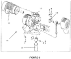
Figure 4 shows an exploded view of the pump drive. - A two (or more)
piston pump system 10 is shown generally inFigure 1 .System 10 is provided with twopumps 12 which arecrank 14 driven theirrespective cranks 14 being offset by about 84° in the preferred embodiment. Anelectric motor 16 drives agear reduction unit 18 which in turn drivescranks 14. Thesystem 10 does not have a mechanical camshaft, but a software algorithm, which acts like one. The algorithm will LEARN and create a unique speed profile, which will mimic the mechanical camshaft. For practical purposes the speed profile of output gear is called Cam profile with software acting as an imaginary camshaft. The algorithm utilizes Crank Angle Estimation, Learn Curve Generation, Smoothing and Advance Timing Calculation - A Smooth CAM speed profile is developed in three steps: (1) Theoretical Cam speed profile is derived; (2) a pump-unique profile is Learned; and (3) Practical Cam profile is developed.
- Theoretical CAM speed profile consists of 360 points (one point per degree). It is derived to deliver constant flow and pressure through the outlet of the system's manifold. The following parameters are used for calculations: degree of displacement of pistons, volume of the piston rod, which effects the real pump volume on the upstroke, change-over duration, at which time no liquid is pumped, and geometries of connecting rod and pump bore.
- A unique set of formulas is used to practically develop a perfect CAM profile for a given system, which insures constant pressure and flow from the pump. The LEARN algorithm also allows the pump to learn the pressure variations while operating.
- Once LEARNED CAM is developed, it is overlaid over the Theoretical CAM and Practical Cam is developed. Note that Theoretical CAM modeling is only approximation, as it is extremely difficult to model effects of check balls and general flexing of the gearbox and pump assemblies. LEARNED CAM takes into
account 100% of variables and therefore it is system specific. Timing of changeovers and ball checks of the Theoretical CAM are verified against LEARNED CAM. Accelerations and decelerations of the LEARNED CAM are also verified against theoretical values and are capped at ±30%. Small, sharp spikes in speed, which were caused by unexplained rapid changes in pressure, are eliminated. - The system does not have a mechanical camshaft, but a software algorithm, which acts like one. The algorithm will LEARN and create a unique speed profile, which will mimic the mechanical camshaft. For practical purposes the speed profile of output gear is called CAM profile with software acting as an imaginary camshaft. The algorithm utilizes the following unique features:
- Crank Angle Estimation
- Learn Curve Generation
- Smoothing
- Advance Timing Calculation
- LEARN CAM algorithm eliminates the need for an encoder by performing angle estimation. One Top Dead Center (TDC) sensor is installed in a gearbox. The sensor is looking at a mark on an output gear. This mark triggers the sensor once every revolution.
- As soon as sensor is triggered, the algorithm starts calculating degree of gear rotation as follows:
- 1. Number of Estimated Motor Revolutions per one 4ms time frame are found first.
- 2. Estimated Angle of output gear rotation is found based on the Number of Estimated Motor Revolutions.
- The software code is installed in a 4ms processor task, which executes every 4 ms. It means that code looks at motor frequency once every 4 ms. Note that actual execution time depends on the amount of code in the task; therefore we cannot assume that our time frame is exactly 4ms long. Software needs provisions to adjust for the error.
- The following formulas describe technique used to calculate angle of rotation:

- Convert to Revolutions per Second:

- Find revolutions per one 4ms time frame:

- Therefore:

- Gear Box Speed Ratio = 75, which means that every 75 revolutions of the motor we have one revolution of the camshaft:
- 1 CAM Revolution = 75
Motor Revolutions 
- This means that 1 motor revolution results in 4.8° of output gear revolution.
- Motor revolutions are tracked based on time (4ms Task Time), therefore camshaft angle can be found at any given number of motor revolutions:
- 360° of CAM = 75 Motor Revolutions
- X° of CAM = # of Estimated Motor Revolutions
- Therefore:


- The system uses speed array of 360 points. Each point represents an angle of crankshaft (output gear) rotation. At the start of the LEARN process, the array is empty with all of its cells filled with zeros. The LEARN process, once started, activates closed loop control system, input of which is pressure of a liquid being pumped, and output is a motor speed. In simplified terms, the system works to deliver constant pressure by adjusting speed of the motor, while recording speed values at every angle of rotation for future use when not in LEARN.
- For example, assume that current angle of rotation is 18°, and measured pressure (current pressure) at this angle is 180PSI. Assume that average pressure is 150PSI. The current pressure is 20% above average. That is the pressure fluctuation, which needs to be eliminated. The system then will adjust speed of the motor by approximately -20% for 18° point to eliminate pressure fluctuation and bring current pressure closer to the average pressure. The process lasts 13 camshaft revolutions, which essentially means that every point is adjusted 13 times. Each time the error will be narrowed to bring pressure at 18° angle closer to the average pressure.
- Key control system elements are:
- Current Pressure - Fluid pressure signal is updated every 10 ms
- Average Pressure - Average pressure is derived with the help of First Order filter function with time constant of 2.4 seconds. For practical purposes, the filtered function can be referred to as a simple averaging function
- Instantaneous Pressure Difference - Instantaneous Pressure Difference = Current Pressure - Average Pressure
- Delta Pressure - Delta pressure is a percent relationship of Instantaneous Pressure Difference to Average Pressure. Refer to
Figure 2 . - Smoothing - is a process of slow error elimination. From
Figure 2 it is seen that error at 18° is 20%. To prevent overcorrection and extra stress on the motor, the error is not corrected by simply increasing motor speed by 20%, which would cause motor to pump more fluid and therefore develop 20% more pressure to compensate for the error. Note that there is square root relationship between pressure and flow. 20% increase in motor speed would only increase pressure by square root of 20%. Instead, the error is eliminated gradually by small increments in speed during 13 LEARN revolutions. First four revolutions the smoothing factor is equaled to 5, next four revolutions the factor is 4, the next four the factor is 3, and the last revolution the factor is 2. The factor represents amount of added weight to the value of degree of revolution. - For example, if LEARN is on its third revolution, the smoothing factor is equaled to 5. The algorithm will take values of previous 5 angles (13°, 14°, 15°, 16°, and 17°) and values of the angles following the current angle (19°, 20°, 21°, 22°, and 23°). The current algorithm will then find average of all of these values, while adding
current angle 18° value twice, so it has more weight. The resulted speed value is assigned toangle 18°. - LEARN CAM Algorithm has provisions to adjust for the error associated with control system response delay and motor slippage. The algorithm will calculate the delay based on the motor frequency and a special constant, LEARN LEAD ANGLE. The constant is motor slippage dependant and is derived by test.


- Frequency Divider = 60;
Example: Assume that estimated angle (Current Angle) is 18°, and motor frequency corresponding to this angle is 20Hz. Assume Learn Lead to be -6.
- When LEARN is in process of calculating error, it attaches it to a Learn Angle and not the Current Angle. If output gear is at 18° and error is at +20%, the LEARN algorithm through its SMOOTHING will determine motor speed correction. Assume that correction was found to be -17.5%. Without ADVANCE TIMING, the LEARN algorithm would command motor speed to be -17.5% when output gear would reach 18° of rotation. This means that the motor speed would have to be adjusted instantly by -17.5%. In a real world it is impossible. Control system needs processing time and motor needs time to react to the command. ADVANCE TIIMING ensures that this command is sent to the motor in advance. In this example advance is -2°, so the algorithm would command - 17.5% change in speed when output gear reaches 16°, and not 18°, therefore giving system time to respond. Refer to
Figure 3 . - It is contemplated that various changes and modifications may be made to the pump control without departing from the spirit and scope of the invention as defined by the following claims.
-
- 1. A method of controlling a pump system having at least two crank driven reciprocating pumps, the cranks for said pumps being offset, said method comprising the steps of:
- developing a theoretical cam speed profile for said pumps taking into account at least some of the parameters of degree of displacement of pistons, volume of the piston rod, change-over duration, and geometries of connecting rod and pump bore.
- developing a pump-unique profile by operating said pump system to produce a learned cam; and
- overlaying said theoretical cam with said learned cam.
- 2. The method of claim 1 wherein said offset is approximately 84°.
- 3. A method of controlling a pump system having at least two crank driven reciprocating pumps, the cranks for said pumps being offset, said method comprising the steps of:
- operating said pump system at a constant speed and collecting output pressure at a selection of crank angle positions;
- forming a pressure profile from said output pressure collection;
- inverting said pressure profile to form a motor speed profile which will reduce pressure variation; and
- repeating the above steps at least once in an iterative process until pressure variation does not exceed a predetermined amount.
- 4. The method of claim 3 further comprising the steps of:
- monitoring pressure variation during operation; and
- adjusting said motor speed profile to reduce pressure variation in the event said predetermined amount is exceeded.
- 5. A method of controlling a pump system having at least two crank driven reciprocating pumps driven by an electric motor, the cranks for said pumps being offset, said method comprising the steps of:
- providing a sensor for at least one of said cranks to sense a particular position in the rotation of the crank and designating that point as a zero point;
- monitoring the frequency of said motor as said crank rotates past said zero point to predict the crankshaft position; and
- at the end of each crank rotation, detecting any difference between said zero point and the predicted zero point and adjusting the prediction.
Claims (2)
- A piston pump system comprising:at least two crank driven reciprocating pumps, the cranks for said pumps being offset; andan electric motor for driving the said at least two pumps, characterised by comprising:a controller for controlling the operation of said pumps by causing the electric motor to drive the pumps according to a motor speed profile that mimics a mechanical cam shaft, wherein the motor speed profile is based upon:a theoretical cam speed profile for said pumps that takes into account at least some of the parameters of degree of displacement of pistons, volume of the piston rod, change-over duration, and geometries of connecting rod and pump bore;a pump-unique profile learned by operating said pump system to produce a learned cam speed profile; anda practical cam speed profile produced by overlaying said theoretical cam speed profile with said learned cam speed profile.
- The piston pump system of claim 1 wherein said offset is approximately 84°.
Applications Claiming Priority (3)
| Application Number | Priority Date | Filing Date | Title |
|---|---|---|---|
| US82699706P | 2006-09-26 | 2006-09-26 | |
| EP07843157.4A EP2076673B1 (en) | 2006-09-26 | 2007-09-25 | Electronic camshaft motor control for piston pump |
| PCT/US2007/079436 WO2008039787A2 (en) | 2006-09-26 | 2007-09-25 | Electronic camshaft motor control for piston pump |
Related Parent Applications (2)
| Application Number | Title | Priority Date | Filing Date |
|---|---|---|---|
| EP07843157.4A Division-Into EP2076673B1 (en) | 2006-09-26 | 2007-09-25 | Electronic camshaft motor control for piston pump |
| EP07843157.4A Division EP2076673B1 (en) | 2006-09-26 | 2007-09-25 | Electronic camshaft motor control for piston pump |
Publications (2)
| Publication Number | Publication Date |
|---|---|
| EP3327285A1 true EP3327285A1 (en) | 2018-05-30 |
| EP3327285B1 EP3327285B1 (en) | 2019-07-03 |
Family
ID=39230920
Family Applications (2)
| Application Number | Title | Priority Date | Filing Date |
|---|---|---|---|
| EP07843157.4A Not-in-force EP2076673B1 (en) | 2006-09-26 | 2007-09-25 | Electronic camshaft motor control for piston pump |
| EP17208455.0A Not-in-force EP3327285B1 (en) | 2006-09-26 | 2007-09-25 | Electronic camshaft motor control for piston pump |
Family Applications Before (1)
| Application Number | Title | Priority Date | Filing Date |
|---|---|---|---|
| EP07843157.4A Not-in-force EP2076673B1 (en) | 2006-09-26 | 2007-09-25 | Electronic camshaft motor control for piston pump |
Country Status (10)
| Country | Link |
|---|---|
| US (1) | US8807958B2 (en) |
| EP (2) | EP2076673B1 (en) |
| JP (1) | JP5275995B2 (en) |
| KR (1) | KR101401849B1 (en) |
| CN (1) | CN101558240B (en) |
| BR (1) | BRPI0717330A2 (en) |
| ES (1) | ES2707812T3 (en) |
| RU (1) | RU2431764C2 (en) |
| TW (1) | TWI411728B (en) |
| WO (1) | WO2008039787A2 (en) |
Families Citing this family (6)
| Publication number | Priority date | Publication date | Assignee | Title |
|---|---|---|---|---|
| RU2526029C2 (en) * | 2012-12-17 | 2014-08-20 | Общество с ограниченной ответственностью научно-технический центр "АРГО" (ООО НТЦ "АРГО") | Control over cylindrical linear induction pump |
| CN103869030B (en) * | 2012-12-18 | 2016-12-28 | 北京普源精仪科技有限责任公司 | A kind of chromatograph of liquid with plunger pump in series and control method thereof |
| CN108171145B (en) * | 2017-12-26 | 2020-08-28 | 迈克医疗电子有限公司 | Flow control method and apparatus, analyzer, and computer-readable storage medium |
| EP4127474B1 (en) | 2020-03-31 | 2025-03-12 | Graco Minnesota Inc. | Pump drive system |
| CN115186415B (en) * | 2022-09-14 | 2022-12-23 | 楚大智能(武汉)技术研究院有限公司 | Cam optimization design method and device |
| CN117246562B (en) * | 2023-10-27 | 2026-04-14 | 西门子(中国)有限公司 | Filling quantity control method and system |
Citations (5)
| Publication number | Priority date | Publication date | Assignee | Title |
|---|---|---|---|---|
| US5145339A (en) | 1989-08-08 | 1992-09-08 | Graco Inc. | Pulseless piston pump |
| US5664937A (en) * | 1994-02-03 | 1997-09-09 | Hitachi, Ltd. | Precisely flow-controlling pump |
| US5725358A (en) | 1995-08-30 | 1998-03-10 | Binks Manufacturing Company | Pressure regulated electric pump |
| DE19849785C1 (en) * | 1998-10-28 | 2000-03-16 | Ott Kg Lewa | Method and device for adjusting feed in oscillating positive-displacement pumps driven by means of driving motor using a rotating shaft and a driving mechanism such as crank gearing, gives versatility in operation |
| WO2002046612A1 (en) | 2000-12-04 | 2002-06-13 | Exel Industries (Societe Anonyme) | Device for pumping thick or turbulence-sensitive products |
Family Cites Families (20)
| Publication number | Priority date | Publication date | Assignee | Title |
|---|---|---|---|---|
| JP2824575B2 (en) * | 1987-08-11 | 1998-11-11 | 株式会社日立製作所 | Low pulsating flow pump |
| JP2745526B2 (en) * | 1988-03-28 | 1998-04-28 | 株式会社島津製作所 | Reciprocating liquid pump |
| SU1671969A1 (en) * | 1989-07-24 | 1991-08-23 | Ворошиловградский машиностроительный институт | Device for automatic control of pumping unit |
| US5635070A (en) * | 1990-07-13 | 1997-06-03 | Isco, Inc. | Apparatus and method for supercritical fluid extraction |
| TW232759B (en) * | 1992-03-16 | 1994-10-21 | Wagner Spray Tech Corp | |
| CA2146177C (en) * | 1995-04-03 | 2000-09-05 | Adrian P. Wade | Intelligent flow analysis network |
| CN1204384A (en) * | 1995-11-14 | 1999-01-06 | 费卢瓦泵有限公司 | Equipment with at least two drive cylinders |
| US5737994A (en) * | 1996-11-27 | 1998-04-14 | Escobosa; Alfonso S. | Digital variable actuation system |
| US6024060A (en) * | 1998-06-05 | 2000-02-15 | Buehrle, Ii; Harry W. | Internal combustion engine valve operating mechanism |
| US6464464B2 (en) * | 1999-03-24 | 2002-10-15 | Itt Manufacturing Enterprises, Inc. | Apparatus and method for controlling a pump system |
| US6264431B1 (en) * | 1999-05-17 | 2001-07-24 | Franklin Electric Co., Inc. | Variable-speed motor drive controller for a pump-motor assembly |
| US6353303B1 (en) * | 1999-10-19 | 2002-03-05 | Fasco Industries, Inc. | Control algorithm for induction motor/blower system |
| NO316653B1 (en) * | 2000-09-15 | 2004-03-22 | Nat Oilwell Norway As | Device by piston machine and method of use in controlling the pistons |
| US6652239B2 (en) * | 2001-03-29 | 2003-11-25 | Kadant Inc. | Motor controller for a hydraulic pump with electrical regeneration |
| US6494685B2 (en) * | 2001-03-29 | 2002-12-17 | Kadant, Inc. | Pump and motor assembly with constant pressure output |
| US6997683B2 (en) * | 2003-01-10 | 2006-02-14 | Teledyne Isco, Inc. | High pressure reciprocating pump and control of the same |
| JP3917108B2 (en) * | 2003-06-03 | 2007-05-23 | ナブテスコ株式会社 | Fluid discharge pump |
| JP2005123220A (en) * | 2003-10-14 | 2005-05-12 | Nikon Corp | Stage control method, exposure method, stage control apparatus and exposure apparatus, and device manufacturing method |
| US8540493B2 (en) * | 2003-12-08 | 2013-09-24 | Sta-Rite Industries, Llc | Pump control system and method |
| RU41811U1 (en) * | 2004-07-06 | 2004-11-10 | Открытое акционерное общество "Татнефть" имени В.Д. Шашина | TWO CYLINDER PISTON PUMP |
-
2007
- 2007-09-25 US US12/442,782 patent/US8807958B2/en not_active Expired - Fee Related
- 2007-09-25 EP EP07843157.4A patent/EP2076673B1/en not_active Not-in-force
- 2007-09-25 EP EP17208455.0A patent/EP3327285B1/en not_active Not-in-force
- 2007-09-25 WO PCT/US2007/079436 patent/WO2008039787A2/en not_active Ceased
- 2007-09-25 JP JP2009530560A patent/JP5275995B2/en not_active Expired - Fee Related
- 2007-09-25 CN CN2007800356724A patent/CN101558240B/en not_active Expired - Fee Related
- 2007-09-25 KR KR1020097008446A patent/KR101401849B1/en not_active Expired - Fee Related
- 2007-09-25 ES ES07843157T patent/ES2707812T3/en active Active
- 2007-09-25 RU RU2009115665/07A patent/RU2431764C2/en not_active IP Right Cessation
- 2007-09-25 BR BRPI0717330-0A2A patent/BRPI0717330A2/en not_active IP Right Cessation
- 2007-09-26 TW TW096135742A patent/TWI411728B/en not_active IP Right Cessation
Patent Citations (5)
| Publication number | Priority date | Publication date | Assignee | Title |
|---|---|---|---|---|
| US5145339A (en) | 1989-08-08 | 1992-09-08 | Graco Inc. | Pulseless piston pump |
| US5664937A (en) * | 1994-02-03 | 1997-09-09 | Hitachi, Ltd. | Precisely flow-controlling pump |
| US5725358A (en) | 1995-08-30 | 1998-03-10 | Binks Manufacturing Company | Pressure regulated electric pump |
| DE19849785C1 (en) * | 1998-10-28 | 2000-03-16 | Ott Kg Lewa | Method and device for adjusting feed in oscillating positive-displacement pumps driven by means of driving motor using a rotating shaft and a driving mechanism such as crank gearing, gives versatility in operation |
| WO2002046612A1 (en) | 2000-12-04 | 2002-06-13 | Exel Industries (Societe Anonyme) | Device for pumping thick or turbulence-sensitive products |
Also Published As
| Publication number | Publication date |
|---|---|
| CN101558240A (en) | 2009-10-14 |
| TW200835856A (en) | 2008-09-01 |
| EP2076673B1 (en) | 2018-11-07 |
| WO2008039787A2 (en) | 2008-04-03 |
| CN101558240B (en) | 2013-03-20 |
| JP5275995B2 (en) | 2013-08-28 |
| WO2008039787A3 (en) | 2008-08-21 |
| KR101401849B1 (en) | 2014-05-29 |
| RU2009115665A (en) | 2010-11-10 |
| US20100034666A1 (en) | 2010-02-11 |
| TWI411728B (en) | 2013-10-11 |
| KR20090057325A (en) | 2009-06-04 |
| US8807958B2 (en) | 2014-08-19 |
| RU2431764C2 (en) | 2011-10-20 |
| EP3327285B1 (en) | 2019-07-03 |
| JP2010505065A (en) | 2010-02-18 |
| EP2076673A2 (en) | 2009-07-08 |
| BRPI0717330A2 (en) | 2013-10-29 |
| EP2076673A4 (en) | 2014-07-23 |
| ES2707812T3 (en) | 2019-04-05 |
Similar Documents
| Publication | Publication Date | Title |
|---|---|---|
| EP3327285B1 (en) | Electronic camshaft motor control for piston pump | |
| US6890156B2 (en) | Reciprocating pump control system | |
| RU2554703C2 (en) | Method, device and driving unit of reciprocating double-acting line pump | |
| US10690129B2 (en) | Method and control device for variable rotational speed control of a displacement pump unit and displacement pump arrangement | |
| US6577089B1 (en) | Pressure control system using input current sensing | |
| US20090220352A1 (en) | Method and Device for Monitoring and Controlling a Hydraulic Actuated Process | |
| CN111425383A (en) | Linear compressor driving method and device, linear compressor and refrigerator | |
| CA2435869A1 (en) | Nutating pump, control system and method of control thereof | |
| US20120076667A1 (en) | Electric motor pump control incorporating pump element position information | |
| CN114198291B (en) | Hydraulic fracturing pump control system | |
| EP3591226B1 (en) | Metering pump and method for controlling a metering pump | |
| US6494685B2 (en) | Pump and motor assembly with constant pressure output | |
| US12297828B2 (en) | Method for controlling a hydraulic drive and hydraulic drive | |
| RU2741267C1 (en) | Method for determination of centrifugal pump flow rate with asynchronous electric drive | |
| EP2249014B1 (en) | Device for controlling fuel injection amount in internal combustion engine | |
| EP4536968A1 (en) | Method for determining operational information of a metering pump | |
| JPH05288109A (en) | Fuel injection timing control apparatus |
Legal Events
| Date | Code | Title | Description |
|---|---|---|---|
| PUAI | Public reference made under article 153(3) epc to a published international application that has entered the european phase |
Free format text: ORIGINAL CODE: 0009012 |
|
| STAA | Information on the status of an ep patent application or granted ep patent |
Free format text: STATUS: THE APPLICATION HAS BEEN PUBLISHED |
|
| AC | Divisional application: reference to earlier application |
Ref document number: 2076673 Country of ref document: EP Kind code of ref document: P |
|
| AK | Designated contracting states |
Kind code of ref document: A1 Designated state(s): AT BE BG CH CY CZ DE DK EE ES FI FR GB GR HU IE IS IT LI LT LU LV MC MT NL PL PT RO SE SI SK TR |
|
| RIN1 | Information on inventor provided before grant (corrected) |
Inventor name: CAMPBELL, JAMES Inventor name: METZA, JOHN Inventor name: SIDLYAREVICH, TIMOTHY |
|
| STAA | Information on the status of an ep patent application or granted ep patent |
Free format text: STATUS: REQUEST FOR EXAMINATION WAS MADE |
|
| 17P | Request for examination filed |
Effective date: 20181130 |
|
| RBV | Designated contracting states (corrected) |
Designated state(s): AT BE BG CH CY CZ DE DK EE ES FI FR GB GR HU IE IS IT LI LT LU LV MC MT NL PL PT RO SE SI SK TR |
|
| GRAP | Despatch of communication of intention to grant a patent |
Free format text: ORIGINAL CODE: EPIDOSNIGR1 |
|
| STAA | Information on the status of an ep patent application or granted ep patent |
Free format text: STATUS: GRANT OF PATENT IS INTENDED |
|
| RIC1 | Information provided on ipc code assigned before grant |
Ipc: F04B 49/06 20060101ALI20190111BHEP Ipc: F04B 15/02 20060101ALI20190111BHEP Ipc: F04B 11/00 20060101AFI20190111BHEP Ipc: F04B 17/03 20060101ALI20190111BHEP |
|
| INTG | Intention to grant announced |
Effective date: 20190129 |
|
| GRAS | Grant fee paid |
Free format text: ORIGINAL CODE: EPIDOSNIGR3 |
|
| GRAA | (expected) grant |
Free format text: ORIGINAL CODE: 0009210 |
|
| STAA | Information on the status of an ep patent application or granted ep patent |
Free format text: STATUS: THE PATENT HAS BEEN GRANTED |
|
| AC | Divisional application: reference to earlier application |
Ref document number: 2076673 Country of ref document: EP Kind code of ref document: P |
|
| AK | Designated contracting states |
Kind code of ref document: B1 Designated state(s): AT BE BG CH CY CZ DE DK EE ES FI FR GB GR HU IE IS IT LI LT LU LV MC MT NL PL PT RO SE SI SK TR |
|
| REG | Reference to a national code |
Ref country code: GB Ref legal event code: FG4D |
|
| REG | Reference to a national code |
Ref country code: CH Ref legal event code: EP Ref country code: AT Ref legal event code: REF Ref document number: 1151327 Country of ref document: AT Kind code of ref document: T Effective date: 20190715 |
|
| REG | Reference to a national code |
Ref country code: IE Ref legal event code: FG4D |
|
| REG | Reference to a national code |
Ref country code: DE Ref legal event code: R096 Ref document number: 602007058779 Country of ref document: DE |
|
| REG | Reference to a national code |
Ref country code: NL Ref legal event code: MP Effective date: 20190703 |
|
| REG | Reference to a national code |
Ref country code: LT Ref legal event code: MG4D |
|
| REG | Reference to a national code |
Ref country code: AT Ref legal event code: MK05 Ref document number: 1151327 Country of ref document: AT Kind code of ref document: T Effective date: 20190703 |
|
| PG25 | Lapsed in a contracting state [announced via postgrant information from national office to epo] |
Ref country code: NL Free format text: LAPSE BECAUSE OF FAILURE TO SUBMIT A TRANSLATION OF THE DESCRIPTION OR TO PAY THE FEE WITHIN THE PRESCRIBED TIME-LIMIT Effective date: 20190703 Ref country code: CZ Free format text: LAPSE BECAUSE OF FAILURE TO SUBMIT A TRANSLATION OF THE DESCRIPTION OR TO PAY THE FEE WITHIN THE PRESCRIBED TIME-LIMIT Effective date: 20190703 Ref country code: PT Free format text: LAPSE BECAUSE OF FAILURE TO SUBMIT A TRANSLATION OF THE DESCRIPTION OR TO PAY THE FEE WITHIN THE PRESCRIBED TIME-LIMIT Effective date: 20191104 Ref country code: BG Free format text: LAPSE BECAUSE OF FAILURE TO SUBMIT A TRANSLATION OF THE DESCRIPTION OR TO PAY THE FEE WITHIN THE PRESCRIBED TIME-LIMIT Effective date: 20191003 Ref country code: LT Free format text: LAPSE BECAUSE OF FAILURE TO SUBMIT A TRANSLATION OF THE DESCRIPTION OR TO PAY THE FEE WITHIN THE PRESCRIBED TIME-LIMIT Effective date: 20190703 Ref country code: AT Free format text: LAPSE BECAUSE OF FAILURE TO SUBMIT A TRANSLATION OF THE DESCRIPTION OR TO PAY THE FEE WITHIN THE PRESCRIBED TIME-LIMIT Effective date: 20190703 Ref country code: FI Free format text: LAPSE BECAUSE OF FAILURE TO SUBMIT A TRANSLATION OF THE DESCRIPTION OR TO PAY THE FEE WITHIN THE PRESCRIBED TIME-LIMIT Effective date: 20190703 Ref country code: SE Free format text: LAPSE BECAUSE OF FAILURE TO SUBMIT A TRANSLATION OF THE DESCRIPTION OR TO PAY THE FEE WITHIN THE PRESCRIBED TIME-LIMIT Effective date: 20190703 |
|
| PG25 | Lapsed in a contracting state [announced via postgrant information from national office to epo] |
Ref country code: GR Free format text: LAPSE BECAUSE OF FAILURE TO SUBMIT A TRANSLATION OF THE DESCRIPTION OR TO PAY THE FEE WITHIN THE PRESCRIBED TIME-LIMIT Effective date: 20191004 Ref country code: IS Free format text: LAPSE BECAUSE OF FAILURE TO SUBMIT A TRANSLATION OF THE DESCRIPTION OR TO PAY THE FEE WITHIN THE PRESCRIBED TIME-LIMIT Effective date: 20191103 Ref country code: ES Free format text: LAPSE BECAUSE OF FAILURE TO SUBMIT A TRANSLATION OF THE DESCRIPTION OR TO PAY THE FEE WITHIN THE PRESCRIBED TIME-LIMIT Effective date: 20190703 Ref country code: LV Free format text: LAPSE BECAUSE OF FAILURE TO SUBMIT A TRANSLATION OF THE DESCRIPTION OR TO PAY THE FEE WITHIN THE PRESCRIBED TIME-LIMIT Effective date: 20190703 |
|
| PG25 | Lapsed in a contracting state [announced via postgrant information from national office to epo] |
Ref country code: TR Free format text: LAPSE BECAUSE OF FAILURE TO SUBMIT A TRANSLATION OF THE DESCRIPTION OR TO PAY THE FEE WITHIN THE PRESCRIBED TIME-LIMIT Effective date: 20190703 |
|
| REG | Reference to a national code |
Ref country code: DE Ref legal event code: R119 Ref document number: 602007058779 Country of ref document: DE |
|
| PG25 | Lapsed in a contracting state [announced via postgrant information from national office to epo] |
Ref country code: IT Free format text: LAPSE BECAUSE OF FAILURE TO SUBMIT A TRANSLATION OF THE DESCRIPTION OR TO PAY THE FEE WITHIN THE PRESCRIBED TIME-LIMIT Effective date: 20190703 Ref country code: RO Free format text: LAPSE BECAUSE OF FAILURE TO SUBMIT A TRANSLATION OF THE DESCRIPTION OR TO PAY THE FEE WITHIN THE PRESCRIBED TIME-LIMIT Effective date: 20190703 Ref country code: EE Free format text: LAPSE BECAUSE OF FAILURE TO SUBMIT A TRANSLATION OF THE DESCRIPTION OR TO PAY THE FEE WITHIN THE PRESCRIBED TIME-LIMIT Effective date: 20190703 Ref country code: DK Free format text: LAPSE BECAUSE OF FAILURE TO SUBMIT A TRANSLATION OF THE DESCRIPTION OR TO PAY THE FEE WITHIN THE PRESCRIBED TIME-LIMIT Effective date: 20190703 Ref country code: PL Free format text: LAPSE BECAUSE OF FAILURE TO SUBMIT A TRANSLATION OF THE DESCRIPTION OR TO PAY THE FEE WITHIN THE PRESCRIBED TIME-LIMIT Effective date: 20190703 |
|
| PG25 | Lapsed in a contracting state [announced via postgrant information from national office to epo] |
Ref country code: SK Free format text: LAPSE BECAUSE OF FAILURE TO SUBMIT A TRANSLATION OF THE DESCRIPTION OR TO PAY THE FEE WITHIN THE PRESCRIBED TIME-LIMIT Effective date: 20190703 Ref country code: MC Free format text: LAPSE BECAUSE OF FAILURE TO SUBMIT A TRANSLATION OF THE DESCRIPTION OR TO PAY THE FEE WITHIN THE PRESCRIBED TIME-LIMIT Effective date: 20190703 Ref country code: IS Free format text: LAPSE BECAUSE OF FAILURE TO SUBMIT A TRANSLATION OF THE DESCRIPTION OR TO PAY THE FEE WITHIN THE PRESCRIBED TIME-LIMIT Effective date: 20200224 |
|
| REG | Reference to a national code |
Ref country code: CH Ref legal event code: PL |
|
| PLBE | No opposition filed within time limit |
Free format text: ORIGINAL CODE: 0009261 |
|
| STAA | Information on the status of an ep patent application or granted ep patent |
Free format text: STATUS: NO OPPOSITION FILED WITHIN TIME LIMIT |
|
| PG2D | Information on lapse in contracting state deleted |
Ref country code: IS |
|
| PG25 | Lapsed in a contracting state [announced via postgrant information from national office to epo] |
Ref country code: IE Free format text: LAPSE BECAUSE OF NON-PAYMENT OF DUE FEES Effective date: 20190925 Ref country code: LU Free format text: LAPSE BECAUSE OF NON-PAYMENT OF DUE FEES Effective date: 20190925 Ref country code: CH Free format text: LAPSE BECAUSE OF NON-PAYMENT OF DUE FEES Effective date: 20190930 Ref country code: DE Free format text: LAPSE BECAUSE OF NON-PAYMENT OF DUE FEES Effective date: 20200401 Ref country code: LI Free format text: LAPSE BECAUSE OF NON-PAYMENT OF DUE FEES Effective date: 20190930 |
|
| REG | Reference to a national code |
Ref country code: BE Ref legal event code: MM Effective date: 20190930 |
|
| 26N | No opposition filed |
Effective date: 20200603 |
|
| PG25 | Lapsed in a contracting state [announced via postgrant information from national office to epo] |
Ref country code: BE Free format text: LAPSE BECAUSE OF NON-PAYMENT OF DUE FEES Effective date: 20190930 Ref country code: SI Free format text: LAPSE BECAUSE OF FAILURE TO SUBMIT A TRANSLATION OF THE DESCRIPTION OR TO PAY THE FEE WITHIN THE PRESCRIBED TIME-LIMIT Effective date: 20190703 |
|
| GBPC | Gb: european patent ceased through non-payment of renewal fee |
Effective date: 20191003 |
|
| PG25 | Lapsed in a contracting state [announced via postgrant information from national office to epo] |
Ref country code: GB Free format text: LAPSE BECAUSE OF NON-PAYMENT OF DUE FEES Effective date: 20191003 Ref country code: FR Free format text: LAPSE BECAUSE OF NON-PAYMENT OF DUE FEES Effective date: 20190930 |
|
| PG25 | Lapsed in a contracting state [announced via postgrant information from national office to epo] |
Ref country code: CY Free format text: LAPSE BECAUSE OF FAILURE TO SUBMIT A TRANSLATION OF THE DESCRIPTION OR TO PAY THE FEE WITHIN THE PRESCRIBED TIME-LIMIT Effective date: 20190703 |
|
| PG25 | Lapsed in a contracting state [announced via postgrant information from national office to epo] |
Ref country code: MT Free format text: LAPSE BECAUSE OF FAILURE TO SUBMIT A TRANSLATION OF THE DESCRIPTION OR TO PAY THE FEE WITHIN THE PRESCRIBED TIME-LIMIT Effective date: 20190703 Ref country code: HU Free format text: LAPSE BECAUSE OF FAILURE TO SUBMIT A TRANSLATION OF THE DESCRIPTION OR TO PAY THE FEE WITHIN THE PRESCRIBED TIME-LIMIT; INVALID AB INITIO Effective date: 20070925 |