EP3327245B1 - Drill rod magazine - Google Patents
Drill rod magazine Download PDFInfo
- Publication number
- EP3327245B1 EP3327245B1 EP17200726.2A EP17200726A EP3327245B1 EP 3327245 B1 EP3327245 B1 EP 3327245B1 EP 17200726 A EP17200726 A EP 17200726A EP 3327245 B1 EP3327245 B1 EP 3327245B1
- Authority
- EP
- European Patent Office
- Prior art keywords
- drill rod
- clamping
- elements
- magazine according
- retaining arms
- Prior art date
- Legal status (The legal status is an assumption and is not a legal conclusion. Google has not performed a legal analysis and makes no representation as to the accuracy of the status listed.)
- Not-in-force
Links
- 229910052751 metal Inorganic materials 0.000 claims description 4
- 239000002184 metal Substances 0.000 claims description 4
- 230000015572 biosynthetic process Effects 0.000 claims description 3
- 238000003780 insertion Methods 0.000 claims description 3
- 230000037431 insertion Effects 0.000 claims description 3
- 230000000717 retained effect Effects 0.000 claims description 3
- 239000000463 material Substances 0.000 description 3
- 239000000853 adhesive Substances 0.000 description 2
- 230000001070 adhesive effect Effects 0.000 description 2
- 238000010276 construction Methods 0.000 description 2
- 230000000694 effects Effects 0.000 description 2
- 229910000831 Steel Inorganic materials 0.000 description 1
- 229910052782 aluminium Inorganic materials 0.000 description 1
- XAGFODPZIPBFFR-UHFFFAOYSA-N aluminium Chemical compound [Al] XAGFODPZIPBFFR-UHFFFAOYSA-N 0.000 description 1
- 230000003190 augmentative effect Effects 0.000 description 1
- 230000001419 dependent effect Effects 0.000 description 1
- 239000013013 elastic material Substances 0.000 description 1
- 238000012423 maintenance Methods 0.000 description 1
- 230000007257 malfunction Effects 0.000 description 1
- 238000004519 manufacturing process Methods 0.000 description 1
- 239000007769 metal material Substances 0.000 description 1
- 239000004033 plastic Substances 0.000 description 1
- 239000010959 steel Substances 0.000 description 1
Images



Classifications
-
- E—FIXED CONSTRUCTIONS
- E21—EARTH OR ROCK DRILLING; MINING
- E21B—EARTH OR ROCK DRILLING; OBTAINING OIL, GAS, WATER, SOLUBLE OR MELTABLE MATERIALS OR A SLURRY OF MINERALS FROM WELLS
- E21B19/00—Handling rods, casings, tubes or the like outside the borehole, e.g. in the derrick; Apparatus for feeding the rods or cables
- E21B19/14—Racks, ramps, troughs or bins, for holding the lengths of rod singly or connected; Handling between storage place and borehole
Definitions
- the invention relates to a drill rod magazine for vertical storage of drill rod elements, having a base frame, on which at least one support means is arranged that has two substantially horizontally directed retaining arms which, by formation of a receiving area, are parallel to and spaced apart from each other, wherein the receiving area is designed for receiving several drill rod elements in a row next to each other and the drill rod elements are retained in a vertical position between the two retaining arms, according to the preamble of claim 1.
- a generic drill rod magazine is known from WO2007/143842 A1 .
- a tensioning element is provided at the retaining arms for each drill rod element .
- a further drill rod magazine can be taken from EP 2 947 258 B1 .
- Another drill rod magazine is known from US 1,718,395 .
- a fork-shaped support means with horizontal retaining arms a plurality of lateral arched tensioning elements is arranged which retain the bar-shaped drill rod elements in their position in their upper area.
- drill rod magazines with fork-shaped support means which are additionally provided with retaining means can be taken from US 2,507,040 , US 2011/0005162 A1 and US 2015/0048038 A1 .
- Another drill rod magazine can be taken from DE 1 812 304 , in which pivotable fixing elements are arranged on the retaining arms of a support means. Between the fixing elements the drill rod elements are arranged and fixed in their vertical storage position.
- the invention is based on the object to provide a drill rod magazine, which, whilst having a simple and robust construction, allows secure storage of drill rod elements.
- the object is solved by a drill rod magazine according to claim 1. Preferred embodiments are cited in the dependent claims.
- a drill rod magazine for vertical storage of drill rod elements having a base frame, on which at least one support means is arranged that has two substantially horizontally directed retaining arms which, by formation of a receiving area, are parallel to and spaced apart from each other, wherein the receiving area is designed for receiving several drill rod elements in a row next to each other and the drill rod elements are retained in a vertical position between the retaining arms, wherein along at least one retaining arm a clamping rod is supported in a movable manner which is in operative connection with a tensioning means that exerts a tensioning force onto the drill rod elements for retaining the drill rod elements in a clamping manner in the receiving area.
- a clamping rod is arranged along at least one retaining arm, the said clamping rod being preferably supported in a movable manner between a clamping position and a retracted position. In the clamping position the clamping rod rests with a clamping force against the external circumference of the drill rod elements so that these are pressed against the opposite retaining arm. As a result, a reliable force-locked fixing of the drill rod elements through a predetermined tensioning force of the clamping rod is attained.
- a clamping rod with a tensioning means is arranged in each case.
- a clamping rod is provided in each case.
- the clamping rods can be produced of any suitable material.
- the clamping rods are formed of a metal profile and, for the purpose of contacting the drill rod elements, have a contact side that is provided with an elastic element.
- the clamping rod has a metal base body consisting in particular of a profile, e.g. of steel or aluminum.
- an elastic element is arranged on a front contact side directed to the drill rod element.
- the clamping and frictional force between the clamping rod and the drill rod element is increased. Due to an elastic deformability of the element on the contact side a certain form-locked fixing of the drill rod element is also brought about.
- the elastic element adapts itself in an arched manner, the contact surface between the clamping rod and the drill rod element is augmented. This also increases the adhesive and frictional forces, which leads to an improved positional fixing.
- the elastic element can be formed of a suitable material, such as a plastic material. According to the invention it is particularly preferred that the elastic element is a rubber strip. This is both inexpensive and robust.
- a further improvement of the retaining effect can be achieved in the case of the drill rod magazine according to the invention in that the clamping rod has a contact side that contacts the drill rod element and is provided with a wave contour.
- the wave contour has wave troughs which are preferably formed to match an external circumference of the drill rod elements.
- the wave-shaped contact side can be formed of a metal material or an elastic material, hence also a rubber strip. The wave contour increases the adhesive and frictional forces.
- the invention is developed further in that several support means are provided, several retaining arms are arranged in a fork-like manner next to each other, by means of at least two pivot levers the clamping rod is supported in a pivotable manner with respect to the retaining arms and the pivot levers are acted upon by tension springs which press the clamping rods into a clamping position.
- tension springs which press the clamping rods into a clamping position.
- tension springs more particularly extension springs, are provided which preferably act upon pivot levers, on which the clamping rod is supported.
- the pivot levers are preferably supported in a pivotable manner in a horizontal plane and enable a good pressing of the clamping rod against vertically arranged drill rod elements.
- the at least one clamping rod has a lead-in slope at its front side.
- the lead-in slope tapers towards the internal side.
- the tensioning means according to the invention is sufficient to retain drill rod elements reliably in their storage position in the drill rod magazine.
- a preferred embodiment variant of the invention resides in the fact that on the retaining arms bar-shaped fixing elements are movably supported by being pivotable between a vertical release position and a horizontal fixing position.
- the fixing elements are arranged at a distance corresponding to the diameter of the drill rod elements so that in the fixing position the fixing elements engage laterally between the drill rod elements arranged next to each other.
- the fixing elements can be actuated individually by separate pivot drives, such as hydraulic or pneumatic positioning cylinders.
- a central drive mechanism with a single drive can be provided, in which case the drive mechanism actuates the fixing elements simultaneously.
- the actuating mechanism can in particular be a lever mechanism which is in operative connection with a central positioning cylinder.
- only one single fixing element can be provided on a retaining arm, in particular at the open end of the receiving space.
- a particularly good positional fixing is achieved in that in the fixing position a drill rod element is received and fixed between two adjacent fixing elements.
- the number of fixing elements preferably corresponds to the maximum number of drill rod elements to be received in the receiving space of a support means.
- the fixing elements are jointly or individually pivotable.
- a drill rod magazine 10 according to the invention is illustrated in an operating state.
- the drill rod magazine 10 has a box-like base frame 12 which has a plate-shaped bearing area 13. Similar to a framework, a first side wall 14, an opposite second side wall 15 and an intermediate wall 16 arranged in-between are mounted on a base plate of the bearing area 13.
- the first side wall 14, the second side wall 15 and the intermediate wall 16 extend vertically and parallel to each other up to an equal height.
- Between the vertically directed walls receiving shelves 20 that are arranged substantially horizontally are provided substantially at three height levels.
- the receiving shelves 20 each have a cross beam 22, on which a plurality of transversely directed retaining arms 24 are mounted which extend in a rake-like manner in the horizontal direction towards a front-side open access area 18 of the drill rod magazine 10.
- the drill rod magazine 10 is foldable by means of a folding mechanism, not explained in greater detail, as known from EP 2 947 258 B1 .
- the upper horizontal receiving shelf 20 is provided with several retaining arms 24 with support means 21 along the horizontal retaining arms 24.
- the support means 21 can also be provided on one or several other receiving shelves 20.
- the support means 21 are illustrated in greater detail in Fig. 2 .
- the horizontally directed retaining arms 24 each have a center beam 25 which is connected in an approximately rectangular manner to the cross beam 22 of the receiving shelf 20. Between two opposite, parallel extending retaining arms 24 a receiving area 26 is designed for receiving drill rod elements, not depicted, in vertical alignment.
- clamping rods 30 are supported in a horizontally movable manner along each longitudinal side of a retaining arm 24.
- the clamping rods 30 each have a lead-in slope 31 to facilitate horizontal insertion of a drill rod element from the front into the receiving area 26 between two clamping rods 30.
- a rubber strip is arranged as an elastic element 34 with a wave contour 36.
- a fixing means 50 with a plurality of parallel arranged bar-shaped fixing elements 52 is provided in each case.
- the fixing elements 52 are each designed horizontally with a distance to each other which is slightly larger than a diameter of the drill rod element to be received.
- the fixing elements 52 which are illustrated in an upward-pivoted idle position in Fig. 2 can be pivoted clockwise by means of the pivot axis 54 from the vertical position into an approximately horizontal operating or fixing position into the receiving area 26 between drill rod elements. In this operating position the fixing elements 52 constitute a form-locked positional securing of received drill rod elements.
- the support means 21 has two opposite base plates 37 which are each fastened on lateral areas of the center beams of the retaining arms.
- a clamping rod 30 is in each case pivotably linked via three double pivot levers 42 arranged offset to each other.
- the pivot levers are attached on the one hand to the clamping rod 30 and on the other hand to the base plate 37.
- a tension spring 44 engages which is fastened at its opposite end on the base plate 37.
- the tension spring 44 is designed as an extension spring, through which the clamping rods 30 are each tensioned relative to each other in an idle position, which is illustrated in Fig. 4 .
- a vertically arranged drill rod element 5 can be inserted e.g. by a crane means into the receiving area 26 between the clamping rods 30 directed towards each other, as illustrated in Fig. 5 .
- the clamping rods 30 are pressed apart contrary to the effect of the tension springs 44 of the tensioning means.
- a tensioning or clamping force is exerted by the opposite clamping rods 30 onto a drill rod element 5 in the receiving area 26. In this way, the position of a drill rod element 5 in the support means 21 is secured.
Landscapes
- Engineering & Computer Science (AREA)
- Life Sciences & Earth Sciences (AREA)
- Geology (AREA)
- Mining & Mineral Resources (AREA)
- Mechanical Engineering (AREA)
- Physics & Mathematics (AREA)
- Environmental & Geological Engineering (AREA)
- Fluid Mechanics (AREA)
- General Life Sciences & Earth Sciences (AREA)
- Geochemistry & Mineralogy (AREA)
- Earth Drilling (AREA)
Description
- The invention relates to a drill rod magazine for vertical storage of drill rod elements, having a base frame, on which at least one support means is arranged that has two substantially horizontally directed retaining arms which, by formation of a receiving area, are parallel to and spaced apart from each other, wherein the receiving area is designed for receiving several drill rod elements in a row next to each other and the drill rod elements are retained in a vertical position between the two retaining arms, according to the preamble of claim 1.
- A generic drill rod magazine is known from
WO2007/143842 A1 . At the retaining arms for each drill rod element a tensioning element is provided. - A further drill rod magazine can be taken from
EP 2 947 258 B1 . On a foldable frame of metal struts several support means with retaining arms are provided which extend horizontally in a fork-like manner. Between the retaining arms drill rod elements can be received and stored vertically. With this drill rod magazine a plurality of drill rod elements can be stored in a compact manner in vertical alignment. - Another drill rod magazine is known from
US 1,718,395 . On a fork-shaped support means with horizontal retaining arms a plurality of lateral arched tensioning elements is arranged which retain the bar-shaped drill rod elements in their position in their upper area. - Further drill rod magazines with fork-shaped support means which are additionally provided with retaining means can be taken from
US 2,507,040 ,US 2011/0005162 A1 andUS 2015/0048038 A1 . - Another drill rod magazine can be taken from
DE 1 812 304 , in which pivotable fixing elements are arranged on the retaining arms of a support means. Between the fixing elements the drill rod elements are arranged and fixed in their vertical storage position. - Although the arrangement of a plurality of fixing elements permits secure storage, retaining arms with a plurality of individually adjustable elements are elaborate in terms of construction, production and maintenance. Especially in rough operation there is the risk of damage or malfunction of the plurality of movable parts.
- The invention is based on the object to provide a drill rod magazine, which, whilst having a simple and robust construction, allows secure storage of drill rod elements. According to the invention the object is solved by a drill rod magazine according to claim 1. Preferred embodiments are cited in the dependent claims.
In accordance with the invention it is provided a drill rod magazine for vertical storage of drill rod elements, having a base frame, on which at least one support means is arranged that has two substantially horizontally directed retaining arms which, by formation of a receiving area, are parallel to and spaced apart from each other, wherein the receiving area is designed for receiving several drill rod elements in a row next to each other and the drill rod elements are retained in a vertical position between the retaining arms, wherein along at least one retaining arm a clamping rod is supported in a movable manner which is in operative connection with a tensioning means that exerts a tensioning force onto the drill rod elements for retaining the drill rod elements in a clamping manner in the receiving area. - According to a basic idea of the invention a clamping rod is arranged along at least one retaining arm, the said clamping rod being preferably supported in a movable manner between a clamping position and a retracted position. In the clamping position the clamping rod rests with a clamping force against the external circumference of the drill rod elements so that these are pressed against the opposite retaining arm. As a result, a reliable force-locked fixing of the drill rod elements through a predetermined tensioning force of the clamping rod is attained.
- According to a preferred further development of the invention provision is made in that in the two opposite retaining arms of a support means a clamping rod with a tensioning means is arranged in each case. Thus, in both retaining arms of a support means a clamping rod is provided in each case. These exert a clamping force against each other, whereby drill rod elements are particularly reliably fixed in a force-locked manner in the receiving space in the support means.
- Basically, the clamping rods can be produced of any suitable material. According to an embodiment variant of the invention it is especially preferred that the clamping rods are formed of a metal profile and, for the purpose of contacting the drill rod elements, have a contact side that is provided with an elastic element. Thus, the clamping rod has a metal base body consisting in particular of a profile, e.g. of steel or aluminum. On a front contact side directed to the drill rod element an elastic element is arranged. Through this, the clamping and frictional force between the clamping rod and the drill rod element is increased. Due to an elastic deformability of the element on the contact side a certain form-locked fixing of the drill rod element is also brought about. Moreover, since the elastic element adapts itself in an arched manner, the contact surface between the clamping rod and the drill rod element is augmented. This also increases the adhesive and frictional forces, which leads to an improved positional fixing.
- The elastic element can be formed of a suitable material, such as a plastic material. According to the invention it is particularly preferred that the elastic element is a rubber strip. This is both inexpensive and robust.
- A further improvement of the retaining effect can be achieved in the case of the drill rod magazine according to the invention in that the clamping rod has a contact side that contacts the drill rod element and is provided with a wave contour. The wave contour has wave troughs which are preferably formed to match an external circumference of the drill rod elements. The wave-shaped contact side can be formed of a metal material or an elastic material, hence also a rubber strip. The wave contour increases the adhesive and frictional forces.
- The invention is developed further in that several support means are provided, several retaining arms are arranged in a fork-like manner next to each other, by means of at least two pivot levers the clamping rod is supported in a pivotable manner with respect to the retaining arms and the pivot levers are acted upon by tension springs which press the clamping rods into a clamping position. To apply the tensioning force different elements can be provided, such as hydraulic or pneumatic tensioning cylinders or rubbery-elastic elements. By particular preference, tension springs, more particularly extension springs, are provided which preferably act upon pivot levers, on which the clamping rod is supported. The pivot levers are preferably supported in a pivotable manner in a horizontal plane and enable a good pressing of the clamping rod against vertically arranged drill rod elements.
- For horizontal insertion of the drill rod elements into the drill rod magazine it is advantageous in accordance with an embodiment variant of the invention that the at least one clamping rod has a lead-in slope at its front side. The lead-in slope tapers towards the internal side.
- Basically, the tensioning means according to the invention is sufficient to retain drill rod elements reliably in their storage position in the drill rod magazine. To further enhance the positional security a preferred embodiment variant of the invention resides in the fact that on the retaining arms bar-shaped fixing elements are movably supported by being pivotable between a vertical release position and a horizontal fixing position. The fixing elements are arranged at a distance corresponding to the diameter of the drill rod elements so that in the fixing position the fixing elements engage laterally between the drill rod elements arranged next to each other. The fixing elements can be actuated individually by separate pivot drives, such as hydraulic or pneumatic positioning cylinders. Advantageously, a central drive mechanism with a single drive can be provided, in which case the drive mechanism actuates the fixing elements simultaneously. The actuating mechanism can in particular be a lever mechanism which is in operative connection with a central positioning cylinder.
- Basically, only one single fixing element can be provided on a retaining arm, in particular at the open end of the receiving space. According to a further development of the invention a particularly good positional fixing is achieved in that in the fixing position a drill rod element is received and fixed between two adjacent fixing elements. Thus, the number of fixing elements preferably corresponds to the maximum number of drill rod elements to be received in the receiving space of a support means.
- Furthermore, it is advantageous for the fixing elements to be jointly or individually pivotable.
- In the following the invention is described further by way of preferred embodiments illustrated schematically in the drawings, wherein show:
- Fig. 1
- a perspective view of a drill rod magazine according to the invention;
- Fig. 2
- an enlarged detailed view of support means on the drill rod magazine of
Fig. 1 ; - Fig. 3
- a perspective view concerning the functioning of a support means;
- Fig. 4
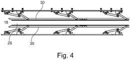
- a plan view of the mechanism of a support means in an idle state; and
- Fig. 5
- a plan view of the support means of
Fig. 4 when receiving a drill rod element. - In
Fig. 1 adrill rod magazine 10 according to the invention is illustrated in an operating state. Thedrill rod magazine 10 has a box-like base frame 12 which has a plate-shapedbearing area 13. Similar to a framework, afirst side wall 14, an oppositesecond side wall 15 and anintermediate wall 16 arranged in-between are mounted on a base plate of the bearingarea 13. Thefirst side wall 14, thesecond side wall 15 and theintermediate wall 16 extend vertically and parallel to each other up to an equal height. Between the vertically directedwalls receiving shelves 20 that are arranged substantially horizontally are provided substantially at three height levels. The receivingshelves 20 each have across beam 22, on which a plurality of transversely directed retainingarms 24 are mounted which extend in a rake-like manner in the horizontal direction towards a front-sideopen access area 18 of thedrill rod magazine 10. - Between the
individual retaining arms 24 slot-shaped free spaces are arranged which are designed as receivingareas 26 for inserting vertically directed drill rod elements. The drill rod elements rest on thebearing area 13 and extend up to one of the receivingshelves 20. - The
drill rod magazine 10 is foldable by means of a folding mechanism, not explained in greater detail, as known fromEP 2 947 258 B1 . - In this embodiment the upper
horizontal receiving shelf 20 is provided with several retainingarms 24 with support means 21 along the horizontal retainingarms 24. The support means 21 can also be provided on one or several other receivingshelves 20. The support means 21 are illustrated in greater detail inFig. 2 . - The horizontally directed retaining
arms 24 each have acenter beam 25 which is connected in an approximately rectangular manner to thecross beam 22 of the receivingshelf 20. Between two opposite, parallel extending retaining arms 24 a receivingarea 26 is designed for receiving drill rod elements, not depicted, in vertical alignment. - Via pivot levers 42
clamping rods 30 are supported in a horizontally movable manner along each longitudinal side of a retainingarm 24. In theaccess area 18 the clampingrods 30 each have a lead-inslope 31 to facilitate horizontal insertion of a drill rod element from the front into the receivingarea 26 between two clampingrods 30. On thecontact side 32 of each clampingrod 30 which is directed towards the drill rod element to be received a rubber strip is arranged as anelastic element 34 with awave contour 36. - Moreover, on an upper side of the retaining arms 24 a fixing means 50 with a plurality of parallel arranged bar-shaped
fixing elements 52 is provided in each case. The fixingelements 52 are each designed horizontally with a distance to each other which is slightly larger than a diameter of the drill rod element to be received. The fixingelements 52 which are illustrated in an upward-pivoted idle position inFig. 2 can be pivoted clockwise by means of thepivot axis 54 from the vertical position into an approximately horizontal operating or fixing position into the receivingarea 26 between drill rod elements. In this operating position the fixingelements 52 constitute a form-locked positional securing of received drill rod elements. - The functioning of a support means 21 for applying clamping forces onto received drill rod elements will be explained in greater detail hereinafter in conjunction with
Figures 3 to 5 . - The support means 21 has two
opposite base plates 37 which are each fastened on lateral areas of the center beams of the retaining arms. On the elongate base plates 37 a clampingrod 30 is in each case pivotably linked via three double pivot levers 42 arranged offset to each other. By way of a pivot joint with a vertical pivot axis the pivot levers are attached on the one hand to the clampingrod 30 and on the other hand to thebase plate 37. In a lower area of eachpivot lever 42 directed to the base plate 37 atension spring 44 engages which is fastened at its opposite end on thebase plate 37. Thetension spring 44 is designed as an extension spring, through which the clampingrods 30 are each tensioned relative to each other in an idle position, which is illustrated inFig. 4 . - From an access area 18 a vertically arranged
drill rod element 5 can be inserted e.g. by a crane means into the receivingarea 26 between the clampingrods 30 directed towards each other, as illustrated inFig. 5 . By inserting thedrill rod element 5 the clampingrods 30 are pressed apart contrary to the effect of the tension springs 44 of the tensioning means. As a result, a tensioning or clamping force is exerted by theopposite clamping rods 30 onto adrill rod element 5 in the receivingarea 26. In this way, the position of adrill rod element 5 in the support means 21 is secured.
Claims (10)
- Drill rod magazine for vertical storage of drill rod elements (5), having a base frame, (12) on which at least one support means (21) is arranged that has two substantially horizontally directed retaining arms (24) which, by formation of a receiving area (26), are parallel to and spaced apart from each other, wherein the receiving area (26) is designed for receiving several drill rod elements (5) in a row next to each other and the drill rod elements (5) are retained in a vertical position between the two retaining arms (24),
wherein along at least one retaining arm (24) a clamping means is supported, characterized in that
the clamping means is a clamping rod (30) being adaptable to rest against the external circumference of a plurality of drill rod elements (5), and
the clamping rod (30) is supported in a movable manner which is in operative connection with a tensioning means (40) for exerting a tensioning force onto the drill rod elements (5) for retaining the drill rod elements (5) in a clamping manner in the receiving area (26). - Drill rod magazine according to claim 1,
wherein in the two opposite retaining arms (24) of a support means (21) a clamping rod (30) with a tensioning means (40) is arranged in each case. - Drill rod magazine according to claim 1,
wherein the at least one clamping rod (30) is formed of a metal profile and, for the purpose of contacting the drill rod element (5), have a contact side (32) that is provided with an elastic element (34). - Drill rod magazine according to claim 3,
wherein the elastic element (34) is a rubber strip. - Drill rod magazine according to claim 1,
wherein the clamping rod (30) has a contact side (32) that contacts the drill rod element (5) and is provided with a wave contour (36). - Drill rod magazine according to claim 1,
wherein- several support means (21) are provided,- several retaining arms (24) are arranged in a fork-like manner next to each other,- by means of at least two pivot levers (42) the clamping rod (30) is supported in a pivotable manner with respect to the retaining arms (24), and- the pivot levers (42) are acted upon by tension (44) springs which press the clamping rods (30) into a clamping position. - Drill rod magazine according to claim 1,
wherein the at least one clamping rod (30) has a lead-in slope (31) at its front side for facilitating horizontal insertion of a drill rod element (5) into the receiving area (26). - Drill rod magazine according to claim 1,
wherein on the retaining arms (24) bar-shaped fixing elements (52) are movably supported by being pivotable between a vertical release position and a horizontal fixing position. - Drill rod magazine according to claim 8,
wherein in the fixing position a drill rod element (5) is received and fixed between two adjacent fixing elements (52). - Drill rod magazine according to claim 8,
wherein the fixing elements (52) are jointly or individually pivotable.
Applications Claiming Priority (1)
| Application Number | Priority Date | Filing Date | Title |
|---|---|---|---|
| US15/361,753 US10167687B2 (en) | 2016-11-28 | 2016-11-28 | Magazine for drilling rods |
Publications (2)
| Publication Number | Publication Date |
|---|---|
| EP3327245A1 EP3327245A1 (en) | 2018-05-30 |
| EP3327245B1 true EP3327245B1 (en) | 2019-06-05 |
Family
ID=60301815
Family Applications (1)
| Application Number | Title | Priority Date | Filing Date |
|---|---|---|---|
| EP17200726.2A Not-in-force EP3327245B1 (en) | 2016-11-28 | 2017-11-09 | Drill rod magazine |
Country Status (2)
| Country | Link |
|---|---|
| US (1) | US10167687B2 (en) |
| EP (1) | EP3327245B1 (en) |
Family Cites Families (10)
| Publication number | Priority date | Publication date | Assignee | Title |
|---|---|---|---|---|
| US1718395A (en) | 1928-05-01 | 1929-06-25 | Frank T Mccoy | Tube rack for derricks |
| US2507040A (en) | 1946-09-20 | 1950-05-09 | Dewey R Moore | Pipe rack |
| US3501017A (en) | 1967-12-04 | 1970-03-17 | Byron Jackson Inc | Finger board and packer apparatus and method |
| US3616941A (en) * | 1969-10-22 | 1971-11-02 | Byron Jackson Inc | Dual horizontal rack |
| MX2007003309A (en) * | 2004-09-22 | 2007-11-09 | Nat Oilwell Lp | Pipe racking system. |
| WO2007143842A1 (en) * | 2006-06-14 | 2007-12-21 | Roboweld Inc. | Systems and methods for autonomous tripping of oil well pipes |
| ATE509182T1 (en) | 2007-12-20 | 2011-05-15 | Itrec Bv | PIPE STORAGE DEVICE |
| US9016382B2 (en) * | 2011-08-05 | 2015-04-28 | Invensys Systems, Inc. | Offshore drilling rig fingerboard latch position indication |
| EP2828468B1 (en) * | 2012-03-20 | 2017-02-22 | Itrec B.V. | Tubulars storage device |
| EP2947258B1 (en) | 2014-05-21 | 2016-09-21 | BAUER Deep Drilling GmbH | Storage rack for drilling pipes |
-
2016
- 2016-11-28 US US15/361,753 patent/US10167687B2/en active Active
-
2017
- 2017-11-09 EP EP17200726.2A patent/EP3327245B1/en not_active Not-in-force
Non-Patent Citations (1)
| Title |
|---|
| None * |
Also Published As
| Publication number | Publication date |
|---|---|
| EP3327245A1 (en) | 2018-05-30 |
| US10167687B2 (en) | 2019-01-01 |
| US20180148987A1 (en) | 2018-05-31 |
Similar Documents
| Publication | Publication Date | Title |
|---|---|---|
| RU2421393C2 (en) | Device to grip, transfer and set package units | |
| US7131363B2 (en) | Paper-cutting apparatus and paper-holding device of the same | |
| RU2011137420A (en) | ADJUSTABLE STAND ASSEMBLY FOR BASKET OF THE DISHWASHING MACHINE | |
| TW200624895A (en) | Mems mirror with tip or piston motion for use in adaptive optics | |
| RU2011131826A (en) | CONVEYOR DEVICE USING A CONVEYOR MOBILE MOBILE ELEMENT | |
| US10167687B2 (en) | Magazine for drilling rods | |
| RU2527431C2 (en) | Device to drive stands and piles into ground | |
| CA2635999A1 (en) | Planar registration of multi-well plate from well side | |
| KR100791495B1 (en) | Angle arc bending device | |
| US20180105376A1 (en) | Device for feeding parts to a manufacturing system | |
| ATE516470T1 (en) | MOUNTING KIT FOR MOUNTING SOLAR MODULES | |
| EP2620246B1 (en) | Working plane for a cutting machine | |
| CN102990333A (en) | Mounting mechanism of fog nozzle and press nozzle of aerial fog valve | |
| JP6381299B2 (en) | Panel fixture | |
| JP3136656U (en) | Shoe storage shelf and shoe storage | |
| CN103950001B (en) | The clamping device of circlip for hole | |
| KR200461968Y1 (en) | Pipe bending device | |
| RU2010116892A (en) | DEVICE FOR CLEANING THE FRAME OF THE COXING CAMERA OF THE COX FURNACE | |
| EP2620245B1 (en) | Cutting machine | |
| CN107193076B (en) | Light guide plate plum blossom hits some head | |
| CN115194722A (en) | Fixing device is deposited to reinforcing bar for construction | |
| JP3146667U (en) | Clamp claw and clamping device | |
| CN101306528A (en) | Circlip tongs | |
| US7093353B2 (en) | Automatic unit for inserting hangers from a strip of attached staples | |
| KR102157737B1 (en) | Mold for manufacturing of BMPCB and manufacturing method using the same |
Legal Events
| Date | Code | Title | Description |
|---|---|---|---|
| PUAI | Public reference made under article 153(3) epc to a published international application that has entered the european phase |
Free format text: ORIGINAL CODE: 0009012 |
|
| STAA | Information on the status of an ep patent application or granted ep patent |
Free format text: STATUS: THE APPLICATION HAS BEEN PUBLISHED |
|
| AK | Designated contracting states |
Kind code of ref document: A1 Designated state(s): AL AT BE BG CH CY CZ DE DK EE ES FI FR GB GR HR HU IE IS IT LI LT LU LV MC MK MT NL NO PL PT RO RS SE SI SK SM TR |
|
| AX | Request for extension of the european patent |
Extension state: BA ME |
|
| STAA | Information on the status of an ep patent application or granted ep patent |
Free format text: STATUS: REQUEST FOR EXAMINATION WAS MADE |
|
| 17P | Request for examination filed |
Effective date: 20180524 |
|
| RBV | Designated contracting states (corrected) |
Designated state(s): AL AT BE BG CH CY CZ DE DK EE ES FI FR GB GR HR HU IE IS IT LI LT LU LV MC MK MT NL NO PL PT RO RS SE SI SK SM TR |
|
| GRAP | Despatch of communication of intention to grant a patent |
Free format text: ORIGINAL CODE: EPIDOSNIGR1 |
|
| STAA | Information on the status of an ep patent application or granted ep patent |
Free format text: STATUS: GRANT OF PATENT IS INTENDED |
|
| INTG | Intention to grant announced |
Effective date: 20190115 |
|
| GRAS | Grant fee paid |
Free format text: ORIGINAL CODE: EPIDOSNIGR3 |
|
| GRAA | (expected) grant |
Free format text: ORIGINAL CODE: 0009210 |
|
| STAA | Information on the status of an ep patent application or granted ep patent |
Free format text: STATUS: THE PATENT HAS BEEN GRANTED |
|
| AK | Designated contracting states |
Kind code of ref document: B1 Designated state(s): AL AT BE BG CH CY CZ DE DK EE ES FI FR GB GR HR HU IE IS IT LI LT LU LV MC MK MT NL NO PL PT RO RS SE SI SK SM TR |
|
| REG | Reference to a national code |
Ref country code: GB Ref legal event code: FG4D |
|
| REG | Reference to a national code |
Ref country code: CH Ref legal event code: EP |
|
| REG | Reference to a national code |
Ref country code: AT Ref legal event code: REF Ref document number: 1140147 Country of ref document: AT Kind code of ref document: T Effective date: 20190615 |
|
| REG | Reference to a national code |
Ref country code: DE Ref legal event code: R096 Ref document number: 602017004325 Country of ref document: DE |
|
| REG | Reference to a national code |
Ref country code: IE Ref legal event code: FG4D |
|
| REG | Reference to a national code |
Ref country code: NL Ref legal event code: FP |
|
| REG | Reference to a national code |
Ref country code: LT Ref legal event code: MG4D |
|
| PG25 | Lapsed in a contracting state [announced via postgrant information from national office to epo] |
Ref country code: ES Free format text: LAPSE BECAUSE OF FAILURE TO SUBMIT A TRANSLATION OF THE DESCRIPTION OR TO PAY THE FEE WITHIN THE PRESCRIBED TIME-LIMIT Effective date: 20190605 Ref country code: SE Free format text: LAPSE BECAUSE OF FAILURE TO SUBMIT A TRANSLATION OF THE DESCRIPTION OR TO PAY THE FEE WITHIN THE PRESCRIBED TIME-LIMIT Effective date: 20190605 Ref country code: AL Free format text: LAPSE BECAUSE OF FAILURE TO SUBMIT A TRANSLATION OF THE DESCRIPTION OR TO PAY THE FEE WITHIN THE PRESCRIBED TIME-LIMIT Effective date: 20190605 Ref country code: HR Free format text: LAPSE BECAUSE OF FAILURE TO SUBMIT A TRANSLATION OF THE DESCRIPTION OR TO PAY THE FEE WITHIN THE PRESCRIBED TIME-LIMIT Effective date: 20190605 Ref country code: LT Free format text: LAPSE BECAUSE OF FAILURE TO SUBMIT A TRANSLATION OF THE DESCRIPTION OR TO PAY THE FEE WITHIN THE PRESCRIBED TIME-LIMIT Effective date: 20190605 Ref country code: FI Free format text: LAPSE BECAUSE OF FAILURE TO SUBMIT A TRANSLATION OF THE DESCRIPTION OR TO PAY THE FEE WITHIN THE PRESCRIBED TIME-LIMIT Effective date: 20190605 |
|
| REG | Reference to a national code |
Ref country code: NO Ref legal event code: T2 Effective date: 20190605 |
|
| PG25 | Lapsed in a contracting state [announced via postgrant information from national office to epo] |
Ref country code: RS Free format text: LAPSE BECAUSE OF FAILURE TO SUBMIT A TRANSLATION OF THE DESCRIPTION OR TO PAY THE FEE WITHIN THE PRESCRIBED TIME-LIMIT Effective date: 20190605 Ref country code: GR Free format text: LAPSE BECAUSE OF FAILURE TO SUBMIT A TRANSLATION OF THE DESCRIPTION OR TO PAY THE FEE WITHIN THE PRESCRIBED TIME-LIMIT Effective date: 20190906 Ref country code: BG Free format text: LAPSE BECAUSE OF FAILURE TO SUBMIT A TRANSLATION OF THE DESCRIPTION OR TO PAY THE FEE WITHIN THE PRESCRIBED TIME-LIMIT Effective date: 20190905 Ref country code: LV Free format text: LAPSE BECAUSE OF FAILURE TO SUBMIT A TRANSLATION OF THE DESCRIPTION OR TO PAY THE FEE WITHIN THE PRESCRIBED TIME-LIMIT Effective date: 20190605 |
|
| REG | Reference to a national code |
Ref country code: AT Ref legal event code: MK05 Ref document number: 1140147 Country of ref document: AT Kind code of ref document: T Effective date: 20190605 |
|
| PG25 | Lapsed in a contracting state [announced via postgrant information from national office to epo] |
Ref country code: AT Free format text: LAPSE BECAUSE OF FAILURE TO SUBMIT A TRANSLATION OF THE DESCRIPTION OR TO PAY THE FEE WITHIN THE PRESCRIBED TIME-LIMIT Effective date: 20190605 Ref country code: PT Free format text: LAPSE BECAUSE OF FAILURE TO SUBMIT A TRANSLATION OF THE DESCRIPTION OR TO PAY THE FEE WITHIN THE PRESCRIBED TIME-LIMIT Effective date: 20191007 Ref country code: SK Free format text: LAPSE BECAUSE OF FAILURE TO SUBMIT A TRANSLATION OF THE DESCRIPTION OR TO PAY THE FEE WITHIN THE PRESCRIBED TIME-LIMIT Effective date: 20190605 Ref country code: RO Free format text: LAPSE BECAUSE OF FAILURE TO SUBMIT A TRANSLATION OF THE DESCRIPTION OR TO PAY THE FEE WITHIN THE PRESCRIBED TIME-LIMIT Effective date: 20190605 Ref country code: CZ Free format text: LAPSE BECAUSE OF FAILURE TO SUBMIT A TRANSLATION OF THE DESCRIPTION OR TO PAY THE FEE WITHIN THE PRESCRIBED TIME-LIMIT Effective date: 20190605 Ref country code: EE Free format text: LAPSE BECAUSE OF FAILURE TO SUBMIT A TRANSLATION OF THE DESCRIPTION OR TO PAY THE FEE WITHIN THE PRESCRIBED TIME-LIMIT Effective date: 20190605 |
|
| PG25 | Lapsed in a contracting state [announced via postgrant information from national office to epo] |
Ref country code: SM Free format text: LAPSE BECAUSE OF FAILURE TO SUBMIT A TRANSLATION OF THE DESCRIPTION OR TO PAY THE FEE WITHIN THE PRESCRIBED TIME-LIMIT Effective date: 20190605 Ref country code: IS Free format text: LAPSE BECAUSE OF FAILURE TO SUBMIT A TRANSLATION OF THE DESCRIPTION OR TO PAY THE FEE WITHIN THE PRESCRIBED TIME-LIMIT Effective date: 20191005 |
|
| REG | Reference to a national code |
Ref country code: DE Ref legal event code: R097 Ref document number: 602017004325 Country of ref document: DE |
|
| PG25 | Lapsed in a contracting state [announced via postgrant information from national office to epo] |
Ref country code: TR Free format text: LAPSE BECAUSE OF FAILURE TO SUBMIT A TRANSLATION OF THE DESCRIPTION OR TO PAY THE FEE WITHIN THE PRESCRIBED TIME-LIMIT Effective date: 20190605 |
|
| PLBE | No opposition filed within time limit |
Free format text: ORIGINAL CODE: 0009261 |
|
| STAA | Information on the status of an ep patent application or granted ep patent |
Free format text: STATUS: NO OPPOSITION FILED WITHIN TIME LIMIT |
|
| PG25 | Lapsed in a contracting state [announced via postgrant information from national office to epo] |
Ref country code: PL Free format text: LAPSE BECAUSE OF FAILURE TO SUBMIT A TRANSLATION OF THE DESCRIPTION OR TO PAY THE FEE WITHIN THE PRESCRIBED TIME-LIMIT Effective date: 20190605 Ref country code: DK Free format text: LAPSE BECAUSE OF FAILURE TO SUBMIT A TRANSLATION OF THE DESCRIPTION OR TO PAY THE FEE WITHIN THE PRESCRIBED TIME-LIMIT Effective date: 20190605 |
|
| 26N | No opposition filed |
Effective date: 20200306 |
|
| PG25 | Lapsed in a contracting state [announced via postgrant information from national office to epo] |
Ref country code: SI Free format text: LAPSE BECAUSE OF FAILURE TO SUBMIT A TRANSLATION OF THE DESCRIPTION OR TO PAY THE FEE WITHIN THE PRESCRIBED TIME-LIMIT Effective date: 20190605 |
|
| PG25 | Lapsed in a contracting state [announced via postgrant information from national office to epo] |
Ref country code: MC Free format text: LAPSE BECAUSE OF FAILURE TO SUBMIT A TRANSLATION OF THE DESCRIPTION OR TO PAY THE FEE WITHIN THE PRESCRIBED TIME-LIMIT Effective date: 20190605 Ref country code: LU Free format text: LAPSE BECAUSE OF NON-PAYMENT OF DUE FEES Effective date: 20191109 |
|
| REG | Reference to a national code |
Ref country code: BE Ref legal event code: MM Effective date: 20191130 |
|
| PG25 | Lapsed in a contracting state [announced via postgrant information from national office to epo] |
Ref country code: FR Free format text: LAPSE BECAUSE OF NON-PAYMENT OF DUE FEES Effective date: 20191130 Ref country code: IE Free format text: LAPSE BECAUSE OF NON-PAYMENT OF DUE FEES Effective date: 20191109 |
|
| REG | Reference to a national code |
Ref country code: DE Ref legal event code: R082 Ref document number: 602017004325 Country of ref document: DE Representative=s name: WUNDERLICH & HEIM PATENTANWAELTE PARTNERSCHAFT, DE Ref country code: DE Ref legal event code: R081 Ref document number: 602017004325 Country of ref document: DE Owner name: BAUER MASCHINEN GMBH, DE Free format text: FORMER OWNER: BAUER DEEP DRILLING GMBH, 86529 SCHROBENHAUSEN, DE |
|
| PG25 | Lapsed in a contracting state [announced via postgrant information from national office to epo] |
Ref country code: BE Free format text: LAPSE BECAUSE OF NON-PAYMENT OF DUE FEES Effective date: 20191130 |
|
| REG | Reference to a national code |
Ref country code: NL Ref legal event code: PD Owner name: BAUER MASCHINEN GMBH; DE Free format text: DETAILS ASSIGNMENT: CHANGE OF OWNER(S), ASSIGNMENT; FORMER OWNER NAME: BAUER DEEP DRILLING GMBH Effective date: 20210316 |
|
| REG | Reference to a national code |
Ref country code: NO Ref legal event code: CHAD Owner name: BAUER MASCHINEN GMBH, DE Ref country code: NO Ref legal event code: CREP Representative=s name: BRYN AARFLOT AS, STORTINGSGATA 8, 0161 OSLO, NORGE |
|
| PG25 | Lapsed in a contracting state [announced via postgrant information from national office to epo] |
Ref country code: CY Free format text: LAPSE BECAUSE OF FAILURE TO SUBMIT A TRANSLATION OF THE DESCRIPTION OR TO PAY THE FEE WITHIN THE PRESCRIBED TIME-LIMIT Effective date: 20190605 |
|
| REG | Reference to a national code |
Ref country code: CH Ref legal event code: PL |
|
| PG25 | Lapsed in a contracting state [announced via postgrant information from national office to epo] |
Ref country code: HU Free format text: LAPSE BECAUSE OF FAILURE TO SUBMIT A TRANSLATION OF THE DESCRIPTION OR TO PAY THE FEE WITHIN THE PRESCRIBED TIME-LIMIT; INVALID AB INITIO Effective date: 20171109 Ref country code: MT Free format text: LAPSE BECAUSE OF FAILURE TO SUBMIT A TRANSLATION OF THE DESCRIPTION OR TO PAY THE FEE WITHIN THE PRESCRIBED TIME-LIMIT Effective date: 20190605 |
|
| PG25 | Lapsed in a contracting state [announced via postgrant information from national office to epo] |
Ref country code: CH Free format text: LAPSE BECAUSE OF NON-PAYMENT OF DUE FEES Effective date: 20201130 Ref country code: LI Free format text: LAPSE BECAUSE OF NON-PAYMENT OF DUE FEES Effective date: 20201130 |
|
| PG25 | Lapsed in a contracting state [announced via postgrant information from national office to epo] |
Ref country code: MK Free format text: LAPSE BECAUSE OF FAILURE TO SUBMIT A TRANSLATION OF THE DESCRIPTION OR TO PAY THE FEE WITHIN THE PRESCRIBED TIME-LIMIT Effective date: 20190605 |
|
| GBPC | Gb: european patent ceased through non-payment of renewal fee |
Effective date: 20211109 |
|
| PG25 | Lapsed in a contracting state [announced via postgrant information from national office to epo] |
Ref country code: GB Free format text: LAPSE BECAUSE OF NON-PAYMENT OF DUE FEES Effective date: 20211109 |
|
| PGFP | Annual fee paid to national office [announced via postgrant information from national office to epo] |
Ref country code: NO Payment date: 20221109 Year of fee payment: 6 Ref country code: NL Payment date: 20221114 Year of fee payment: 6 Ref country code: IT Payment date: 20221114 Year of fee payment: 6 Ref country code: DE Payment date: 20221108 Year of fee payment: 6 |
|
| REG | Reference to a national code |
Ref country code: DE Ref legal event code: R119 Ref document number: 602017004325 Country of ref document: DE |
|
| REG | Reference to a national code |
Ref country code: NL Ref legal event code: MM Effective date: 20231201 |
|
| PG25 | Lapsed in a contracting state [announced via postgrant information from national office to epo] |
Ref country code: NO Free format text: LAPSE BECAUSE OF NON-PAYMENT OF DUE FEES Effective date: 20231130 |
|
| PG25 | Lapsed in a contracting state [announced via postgrant information from national office to epo] |
Ref country code: NL Free format text: LAPSE BECAUSE OF NON-PAYMENT OF DUE FEES Effective date: 20231201 |
|
| PG25 | Lapsed in a contracting state [announced via postgrant information from national office to epo] |
Ref country code: NL Free format text: LAPSE BECAUSE OF NON-PAYMENT OF DUE FEES Effective date: 20231201 |
|
| PG25 | Lapsed in a contracting state [announced via postgrant information from national office to epo] |
Ref country code: DE Free format text: LAPSE BECAUSE OF NON-PAYMENT OF DUE FEES Effective date: 20240601 |
|
| PG25 | Lapsed in a contracting state [announced via postgrant information from national office to epo] |
Ref country code: DE Free format text: LAPSE BECAUSE OF NON-PAYMENT OF DUE FEES Effective date: 20240601 |
|
| PG25 | Lapsed in a contracting state [announced via postgrant information from national office to epo] |
Ref country code: IT Free format text: LAPSE BECAUSE OF NON-PAYMENT OF DUE FEES Effective date: 20231109 |
|
| PG25 | Lapsed in a contracting state [announced via postgrant information from national office to epo] |
Ref country code: IT Free format text: LAPSE BECAUSE OF NON-PAYMENT OF DUE FEES Effective date: 20231109 |