EP3326856A1 - An electric multisystem for a rail vehicle - Google Patents
An electric multisystem for a rail vehicle Download PDFInfo
- Publication number
- EP3326856A1 EP3326856A1 EP16200213.3A EP16200213A EP3326856A1 EP 3326856 A1 EP3326856 A1 EP 3326856A1 EP 16200213 A EP16200213 A EP 16200213A EP 3326856 A1 EP3326856 A1 EP 3326856A1
- Authority
- EP
- European Patent Office
- Prior art keywords
- transformer
- secondary winding
- electric
- line
- voltage
- Prior art date
- Legal status (The legal status is an assumption and is not a legal conclusion. Google has not performed a legal analysis and makes no representation as to the accuracy of the status listed.)
- Granted
Links
Images


Classifications
-
- H—ELECTRICITY
- H02—GENERATION; CONVERSION OR DISTRIBUTION OF ELECTRIC POWER
- H02M—APPARATUS FOR CONVERSION BETWEEN AC AND AC, BETWEEN AC AND DC, OR BETWEEN DC AND DC, AND FOR USE WITH MAINS OR SIMILAR POWER SUPPLY SYSTEMS; CONVERSION OF DC OR AC INPUT POWER INTO SURGE OUTPUT POWER; CONTROL OR REGULATION THEREOF
- H02M3/00—Conversion of DC power input into DC power output
- H02M3/02—Conversion of DC power input into DC power output without intermediate conversion into AC
- H02M3/04—Conversion of DC power input into DC power output without intermediate conversion into AC by static converters
- H02M3/10—Conversion of DC power input into DC power output without intermediate conversion into AC by static converters using discharge tubes with control electrode or semiconductor devices with control electrode
- H02M3/145—Conversion of DC power input into DC power output without intermediate conversion into AC by static converters using discharge tubes with control electrode or semiconductor devices with control electrode using devices of a triode or transistor type requiring continuous application of a control signal
- H02M3/155—Conversion of DC power input into DC power output without intermediate conversion into AC by static converters using discharge tubes with control electrode or semiconductor devices with control electrode using devices of a triode or transistor type requiring continuous application of a control signal using semiconductor devices only
-
- B—PERFORMING OPERATIONS; TRANSPORTING
- B60—VEHICLES IN GENERAL
- B60L—PROPULSION OF ELECTRICALLY-PROPELLED VEHICLES; SUPPLYING ELECTRIC POWER FOR AUXILIARY EQUIPMENT OF ELECTRICALLY-PROPELLED VEHICLES; ELECTRODYNAMIC BRAKE SYSTEMS FOR VEHICLES IN GENERAL; MAGNETIC SUSPENSION OR LEVITATION FOR VEHICLES; MONITORING OPERATING VARIABLES OF ELECTRICALLY-PROPELLED VEHICLES; ELECTRIC SAFETY DEVICES FOR ELECTRICALLY-PROPELLED VEHICLES
- B60L9/00—Electric propulsion with power supply external to the vehicle
- B60L9/16—Electric propulsion with power supply external to the vehicle using AC induction motors
- B60L9/30—Electric propulsion with power supply external to the vehicle using AC induction motors fed from different kinds of power-supply lines
-
- H—ELECTRICITY
- H02—GENERATION; CONVERSION OR DISTRIBUTION OF ELECTRIC POWER
- H02M—APPARATUS FOR CONVERSION BETWEEN AC AND AC, BETWEEN AC AND DC, OR BETWEEN DC AND DC, AND FOR USE WITH MAINS OR SIMILAR POWER SUPPLY SYSTEMS; CONVERSION OF DC OR AC INPUT POWER INTO SURGE OUTPUT POWER; CONTROL OR REGULATION THEREOF
- H02M7/00—Conversion of AC power input into DC power output; Conversion of DC power input into AC power output
- H02M7/02—Conversion of AC power input into DC power output without possibility of reversal
- H02M7/04—Conversion of AC power input into DC power output without possibility of reversal by static converters
- H02M7/043—Conversion of AC power input into DC power output without possibility of reversal by static converters using transformers or inductors only
-
- H—ELECTRICITY
- H02—GENERATION; CONVERSION OR DISTRIBUTION OF ELECTRIC POWER
- H02M—APPARATUS FOR CONVERSION BETWEEN AC AND AC, BETWEEN AC AND DC, OR BETWEEN DC AND DC, AND FOR USE WITH MAINS OR SIMILAR POWER SUPPLY SYSTEMS; CONVERSION OF DC OR AC INPUT POWER INTO SURGE OUTPUT POWER; CONTROL OR REGULATION THEREOF
- H02M7/00—Conversion of AC power input into DC power output; Conversion of DC power input into AC power output
- H02M7/02—Conversion of AC power input into DC power output without possibility of reversal
- H02M7/04—Conversion of AC power input into DC power output without possibility of reversal by static converters
- H02M7/12—Conversion of AC power input into DC power output without possibility of reversal by static converters using discharge tubes with control electrode or semiconductor devices with control electrode
- H02M7/21—Conversion of AC power input into DC power output without possibility of reversal by static converters using discharge tubes with control electrode or semiconductor devices with control electrode using devices of a triode or transistor type requiring continuous application of a control signal
- H02M7/217—Conversion of AC power input into DC power output without possibility of reversal by static converters using discharge tubes with control electrode or semiconductor devices with control electrode using devices of a triode or transistor type requiring continuous application of a control signal using semiconductor devices only
- H02M7/219—Conversion of AC power input into DC power output without possibility of reversal by static converters using discharge tubes with control electrode or semiconductor devices with control electrode using devices of a triode or transistor type requiring continuous application of a control signal using semiconductor devices only in a bridge configuration
-
- B—PERFORMING OPERATIONS; TRANSPORTING
- B60—VEHICLES IN GENERAL
- B60L—PROPULSION OF ELECTRICALLY-PROPELLED VEHICLES; SUPPLYING ELECTRIC POWER FOR AUXILIARY EQUIPMENT OF ELECTRICALLY-PROPELLED VEHICLES; ELECTRODYNAMIC BRAKE SYSTEMS FOR VEHICLES IN GENERAL; MAGNETIC SUSPENSION OR LEVITATION FOR VEHICLES; MONITORING OPERATING VARIABLES OF ELECTRICALLY-PROPELLED VEHICLES; ELECTRIC SAFETY DEVICES FOR ELECTRICALLY-PROPELLED VEHICLES
- B60L2220/00—Electrical machine types; Structures or applications thereof
- B60L2220/50—Structural details of electrical machines
- B60L2220/54—Windings for different functions
-
- H—ELECTRICITY
- H02—GENERATION; CONVERSION OR DISTRIBUTION OF ELECTRIC POWER
- H02M—APPARATUS FOR CONVERSION BETWEEN AC AND AC, BETWEEN AC AND DC, OR BETWEEN DC AND DC, AND FOR USE WITH MAINS OR SIMILAR POWER SUPPLY SYSTEMS; CONVERSION OF DC OR AC INPUT POWER INTO SURGE OUTPUT POWER; CONTROL OR REGULATION THEREOF
- H02M1/00—Details of apparatus for conversion
- H02M1/0083—Converters characterised by their input or output configuration
- H02M1/009—Converters characterised by their input or output configuration having two or more independently controlled outputs
-
- H—ELECTRICITY
- H02—GENERATION; CONVERSION OR DISTRIBUTION OF ELECTRIC POWER
- H02M—APPARATUS FOR CONVERSION BETWEEN AC AND AC, BETWEEN AC AND DC, OR BETWEEN DC AND DC, AND FOR USE WITH MAINS OR SIMILAR POWER SUPPLY SYSTEMS; CONVERSION OF DC OR AC INPUT POWER INTO SURGE OUTPUT POWER; CONTROL OR REGULATION THEREOF
- H02M3/00—Conversion of DC power input into DC power output
- H02M3/02—Conversion of DC power input into DC power output without intermediate conversion into AC
- H02M3/04—Conversion of DC power input into DC power output without intermediate conversion into AC by static converters
- H02M3/10—Conversion of DC power input into DC power output without intermediate conversion into AC by static converters using discharge tubes with control electrode or semiconductor devices with control electrode
- H02M3/145—Conversion of DC power input into DC power output without intermediate conversion into AC by static converters using discharge tubes with control electrode or semiconductor devices with control electrode using devices of a triode or transistor type requiring continuous application of a control signal
- H02M3/155—Conversion of DC power input into DC power output without intermediate conversion into AC by static converters using discharge tubes with control electrode or semiconductor devices with control electrode using devices of a triode or transistor type requiring continuous application of a control signal using semiconductor devices only
- H02M3/1552—Boost converters exploiting the leakage inductance of a transformer or of an alternator as boost inductor
-
- Y—GENERAL TAGGING OF NEW TECHNOLOGICAL DEVELOPMENTS; GENERAL TAGGING OF CROSS-SECTIONAL TECHNOLOGIES SPANNING OVER SEVERAL SECTIONS OF THE IPC; TECHNICAL SUBJECTS COVERED BY FORMER USPC CROSS-REFERENCE ART COLLECTIONS [XRACs] AND DIGESTS
- Y02—TECHNOLOGIES OR APPLICATIONS FOR MITIGATION OR ADAPTATION AGAINST CLIMATE CHANGE
- Y02T—CLIMATE CHANGE MITIGATION TECHNOLOGIES RELATED TO TRANSPORTATION
- Y02T10/00—Road transport of goods or passengers
- Y02T10/60—Other road transportation technologies with climate change mitigation effect
- Y02T10/64—Electric machine technologies in electromobility
Definitions
- the present invention relates to an electric multisystem configured to be arranged on board a rail vehicle and comprising
- Such electric multisystems are of interest on board rail vehicles which may be driven both on rail sections energized by an AC-contact line and those energized by DC.
- said connector means When passing from one of these types of rail sections to the other type said connector means will take care of a change of the electric system to be fed with another type of electric power, AC or DC, than before while allowing electric motors for driving the vehicle and other electric equipment of the vehicle to operate as before.
- the invention is not restricted to such electric multisystems for any special type of rail vehicles, but the rail vehicle may be of any conceivable type.
- the invention is neither restricted to any particular levels of the voltage of the AC-contact line or the DC-contact line through which the system is fed.
- DC-contact line will in this disclosure refer to both the possibility of a third rail contact line (as in UK) and that of a DC overhead contact line, such as for instance for a "tram-train”.
- Fig. 1 illustrates schematically a possible design of an electric system of the type defined in the introduction without having a possible connection thereof to a DC-contact line shown, and the construction of this known system will now be described for facilitating the understanding of the present invention. It is shown how electric power is fed to a rail vehicle 1 from an AC-contact line 2 and used in the vehicle.
- the vehicle is configured to move along the AC-contact line 2, which may for example carry a single phase alternating voltage of 15 kV and 16 2/3 Hz (Sweden) or 25 kV and 50 Hz (Denmark).
- the vehicle has a transformer 3 for transforming the voltage from the contact line 2 to a suitable level.
- the transformer has here a primary winding 4 and two secondary windings 5, 6 one of which being connected to a line converter 7 for delivering a direct voltage of for example 1.5-3 kV, such as 1.65 kV, on the output thereof.
- This direct voltage of the DC intermediate link 18 is delivered to an auxiliary converter 8, which is controlled by a control unit 9 for generating a train of pulses according to a Pulse Width Modulation pattern for delivering a three-phase alternating voltage on the output thereof.
- the output of the auxiliary converter 8 is connected to a three-phase transformer 10 as well as harmonic filters 11 for smoothing out the alternating voltage delivered by a distribution network 12 to sockets arranged in the rail vehicle, such as for connection of computers, and to lightening, heating, and other appliances.
- the other secondary winding 5 of the transformer is connected to a line converter 13 configured to deliver direct voltage on the output thereof to a DC intermediate link 14 forming the input to a motor converter 15 controlled by a control unit 16 in a similar way as the control carried out by the control unit 9 for delivering a three-phase alternating voltage on the output of the motor converter to motors 17 in the form of electric machines, for driving the vehicle.
- the electric system shown in Fig.1 is an AC-system, and there are different options for modifying it to be a multisystem also allowing feeding of electric power thereto in the form of such power provided by a DC-contact line.
- One such option is to design a said connector means to connect a DC-contact line via a line filter inductor to the DC intermediate link 14 for feeding electric power to the electric motors driving the vehicle and make a corresponding connection of the DC-contact line to the DC intermediate link 18 connected to the auxiliary converter 8.
- the respective line converter 13, 7 will then be inactive.
- Another option is to feed the DC link 14, 18 via a dedicated DC to DC chopper using a dedicated chopper inductor when supplied from a DC contact line. This is known through EP 2 695 763 A2 , in which the secondary winding of the transformer is then used as a line filter inductor.
- a further option is disclosed in the pamphlet "High speed dual voltage locomotive" of Ingeteam Traction from 09/2008.
- a DC line voltage may be connected to one end of the secondary windings, with the other ends still connected to a phase of the line converter.
- the secondary windings then act as line filter inductors, with the line current reaching the DC intermediate link via the diode in the upper part of the line converter phase leg. If the line converter to which the secondary winding is connected is switched it may operate as a DC - DC chopper for obtaining a reduction of the range of possible levels of the voltage delivered to said DC intermediate link, but as there is no separate line filter capacitor and no separate chopper inductor, this will be at the expense of a chopper frequency line current harmonic.
- the DC-contact line is connected to one end of the secondary winding of the transformer only one of the phase-legs of each bridge in the line converter may be used, since control of the other phase-leg would result in a short circuit between the DC voltage and earth. This results in not only a low level of electric power transferrable through the line converter but also a high content of harmonics due to the low switching frequency possible.
- the object of the present invention is to provide an electric multisystem of the type discusses above being improved in at least some aspect with respect to such systems already known.
- the line converter may be controlled to, together with the inductance of each half of the secondary winding used as a step-up chopper inductor, act as a DC to DC-chopper for adjusting the level of the DC voltage delivered to the DC intermediate link.
- This design enables using both phase-legs of the line converter resulting in a transferrable electric power being twice the electric power transferrable would the DC voltage be connected to one end of the secondary winding, and the ripple frequency in the line current will then also be twice as high resulting in a lower content of harmonics.
- the voltage delivered on the DC intermediate link may be adjusted by appropriate control of the line converter, so that the design and dimensioning of the rest of the electric system may be optimized for a narrow DC link voltage range, despite that the DC line voltage supplied to the vehicle varies in a much wider range, e. g. 500 - 1000 V DC or 1000 V - 1950 V DC.
- a system for nominal line voltages of 750 V DC and 25 kV or 15 kV AC may for example in both AC and DC mode have the line converter regulating the DC intermediate link to a voltage above the maximum value achieved without switching the semiconductor switch of the DC to DC chopper, e. g. 1 800 V DC.
- a very similar system may also be used for the same AC line voltage, but for a DC line voltage with a range reaching above the regulated DC intermediate link value, e. g. when the regulated DC link voltage is 1 800 V DC it may be used for DC lines with a nominal line voltage of 1 500 V DC, i. e. with the range 1 000 - 1 950 V.
- the line converter operating as DC to DC chopper will be able to increase and regulate any line voltage below the desired DC link voltage level, e. g. 1 800 V, but when the line voltage exceeds this level this higher voltage will inevitably reach the DC link via the rectifying members of the upper valves in the phase legs and the DC link voltage is no longer regulated.
- the narrower DC link voltage range means that most components of the system can be shared with an electric system built only for AC line voltage supply, thereby reducing design, material and production cost. It is even possible to design a multisystem which can operate on two different DC line voltages and at least one AC line voltage, such as 750 V DC tram lines and 1500 V DC and 25 kV AC main lines in France or 1500 V DC and 25 kV AC lines in France and 3 kV DC and 25 kV AC lines in Italy, and for each of these contact line voltages will have a DC intermediate link voltage keeping within a narrow range, so that most part of the system may be optimized for this narrow DC link voltage range.
- the electric multisystem comprises means configured to determine the level of the voltage on the DC intermediate link when the second connector means connects the midpoint of the secondary winding of the transformer to the second connection point, and it comprises means configured to compare the level of this DC intermediate link voltage with a predetermined level, and the control unit is configured to control the line converter to deliver a DC voltage on the DC intermediate link of a level approaching said predetermined level.
- “Approaching” is here used for stating that it is not necessary that the line converter is controlled so that the level of the DC voltage delivered to the DC intermediate link is exactly the same as said predetermined level, but it may for different reasons be chosen to for instance increase the level from 500 - 1 000 V to 1 650 - 1800 V although the predetermined level is 1 800 V.
- control unit is configured to control the current valves of the at least two phase-legs of the line converter with the aim to cancel out harmonics.
- This aim will be addressed by interleaving the PWM patterns in all chopper phases. Interleaving means that the different pulses in different phases connected to the same supply are synchronised and distributed uniformly in time so that the total line (or load) current has a current ripple as if the switching frequency were higher than the actual frequency of each phases.
- said line converter has two said bridges connected in parallel to said DC intermediate link, and the transformer comprises two said secondary windings each divided into two halves and connected to a said bridge each of the line converter.
- the electric system comprises a motor converter connected to the DC intermediate link and controlled by a control unit for delivering a three-phase alternating voltage on the output thereof to one or several motors in the form of electric machines for driving the vehicle.
- the design of the electric multisystem according to the invention will ensure that the motor converter will always get a DC voltage suitable for providing the electric motors with a desired alternating voltage.
- the electric multisystem has two line converters connected to a said DC intermediate link each, and one of the DC intermediate links may then be connected to an auxiliary converter connected through a further transformer to sockets of a distribution network in the rail vehicle, such as for connection of computers, and to lightning, heating, and other appliances as shown in Fig. 1 .
- a distribution network in the rail vehicle such as for connection of computers, and to lightning, heating, and other appliances as shown in Fig. 1 .
- the invention also relates to a method for controlling an electric multisystem on board a rail vehicle according to the appended independent method claim.
- the advantages of such a method and the embodiment thereof defined in the dependent method claim appear clearly from the above discussion of the electric multisystem of the present invention.
- the invention also relates to a rail vehicle comprising an electric multisystem according to the present invention.
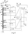
- the DC-contact line 20 has a line inductance 21. Depending on EMC requirements a separate inductor may be needed to be added to the line inductance, and a line filter inductor 100 considering this is here indicated. It is schematically illustrated how a first connector means 22 in the form of a system changeover switch is configured to, one at a time, connect either a first connection point a of the electric system to an AC-contact line or a second connection point b of the electric system to a DC-contact line, in which for these connections to AC and DC supply the same pantograph 23 is used for both types of contact lines.
- a charging circuit not shown is arranged to charge the capacitor 25 without tripping the feeding supply fuses also not shown.
- This capacitor 25 has its main function as a filter component.
- Each line converter 13, 7 has here two bridges 26 of the type shown in Fig. 3 connected in parallel to a respective DC intermediate link 14, 18.
- Each such bridge has two phase-legs 27, 28 connected in parallel between opposite poles 29, 30 of the DC intermediate link and each phase-leg has two current valves 31-34 connected in series.
- Each current valve has a semiconductor device 35-38 of turn off type, such as an IGBT, and a rectifying member 39-42, such as a rectifying diode, connected in anti-parallel therewith.
- Midpoints 43, 44 of the two phase legs are connected to different ends of a secondary winding 80 in common. It is schematically illustrated in Fig. 2 how the transformer 3 for each line converter has two secondary windings 80, 81 and 82, 83 to be connected to a bridge each of the respective line converter and that each such secondary winding is divided into two halves 51-54, 61-64.
- FIG. 3 It is shown in Fig. 3 how the DC voltage is connected to a midpoint 55 between the respective two secondary windings 51, 52. Second connector means for this are schematically illustrated in Fig. 2 at 70, 71.
- a control unit 19 configured to control the current valves shown in Fig. 3 of the line converter will do this by controlling the semiconductor devices 35-38 thereof, and this control unit is when the electric system is connected to a DC-contact line configured to control the line converter to together with the inductor of each secondary winding half 51, 52 used as a step-up chopper inductor act as a DC to DC-chopper for adjusting the level of the DC voltage delivered to the capacitor 72 of the DC intermediate link 14.
- control unit 19 may receive information about the actual level of the DC intermediate link voltage delivered to the electric system for considering this level when controlling the bridges of the line converter 13 as a DC to a DC-chopper for obtaining the voltage level desired on the DC intermediate link 14. This means that if the motor converter 15 and the motors 17 are designed for a rated voltage of 1 800 VDC and the DC-contact line delivers a DC voltage to the electric system of only 500 - 900 VDC the control unit 19 may control the line converter 13 to step up the voltage to 1 800 VDC or a level close thereto.
- the current valves of both phase legs 27, 28 may be controlled with interleaving to provide the DC intermediate link 14 with electric power and a ripple frequency being twice as high as would the DC voltage be connected to one side of the secondary winding and only one of the phase legs used as chopper, which results in a lower content of harmonics and also an electric power transferrable through the line converter being twice as high.
- the number of line converters of the electric system may be different than shown, such as 1 or 3.
- Each current valve may have a plurality of semiconductor devices connected in series to be controlled as one single switch. For just mention a couple of possible modifications.
- connection does not mean that a connection has to be made without any intermediate parts in the connection line between two parts connected to each other.
- Said second connector means will for instance in practice connect the midpoint of a secondary winding via one or more parts to the second connection point. But such parts have been omitted in the figures for the sake of simplicity. The same applies for example also to the connection of the charging circuit to the second connection point.
Landscapes
- Engineering & Computer Science (AREA)
- Power Engineering (AREA)
- Life Sciences & Earth Sciences (AREA)
- Sustainable Development (AREA)
- Sustainable Energy (AREA)
- Transportation (AREA)
- Mechanical Engineering (AREA)
- Electric Propulsion And Braking For Vehicles (AREA)
Abstract
Description
- The present invention relates to an electric multisystem configured to be arranged on board a rail vehicle and comprising
- a first connector means configured to one at a time connect either a first connection point of the electric system to an AC-contact line or a second connection point of the electric system to a DC-contact line,
- a transformer comprising a primary winding to which the first connection point is connected,
- a line converter to which a secondary winding of the transformer is connected and which has at least one bridge with two phase-legs connected in parallel between opposite poles of a DC intermediate link and having each at least two current valves connected in series, each said current valve comprising a semiconductor device of turn-off type and a rectifying member connected in anti-parallel therewith, a midpoint of each phase-leg dividing the phase-leg in two identical halves being connected to said secondary winding of the transformer, and
- a control unit configured to control the current valves of the line converter by controlling said semiconductor devices thereof.
- Such electric multisystems are of interest on board rail vehicles which may be driven both on rail sections energized by an AC-contact line and those energized by DC. When passing from one of these types of rail sections to the other type said connector means will take care of a change of the electric system to be fed with another type of electric power, AC or DC, than before while allowing electric motors for driving the vehicle and other electric equipment of the vehicle to operate as before.
- The invention is not restricted to such electric multisystems for any special type of rail vehicles, but the rail vehicle may be of any conceivable type. The invention is neither restricted to any particular levels of the voltage of the AC-contact line or the DC-contact line through which the system is fed. "DC-contact line" will in this disclosure refer to both the possibility of a third rail contact line (as in UK) and that of a DC overhead contact line, such as for instance for a "tram-train".
-
Fig. 1 illustrates schematically a possible design of an electric system of the type defined in the introduction without having a possible connection thereof to a DC-contact line shown, and the construction of this known system will now be described for facilitating the understanding of the present invention. It is shown how electric power is fed to arail vehicle 1 from an AC-contact line 2 and used in the vehicle. The vehicle is configured to move along the AC-contact line 2, which may for example carry a single phase alternating voltage of 15 kV and 16 2/3 Hz (Sweden) or 25 kV and 50 Hz (Denmark). The vehicle has a transformer 3 for transforming the voltage from thecontact line 2 to a suitable level. The transformer has here a primary winding 4 and twosecondary windings line converter 7 for delivering a direct voltage of for example 1.5-3 kV, such as 1.65 kV, on the output thereof. This direct voltage of the DCintermediate link 18 is delivered to anauxiliary converter 8, which is controlled by a control unit 9 for generating a train of pulses according to a Pulse Width Modulation pattern for delivering a three-phase alternating voltage on the output thereof. The output of theauxiliary converter 8 is connected to a three-phase transformer 10 as well asharmonic filters 11 for smoothing out the alternating voltage delivered by adistribution network 12 to sockets arranged in the rail vehicle, such as for connection of computers, and to lightening, heating, and other appliances. - The other
secondary winding 5 of the transformer is connected to aline converter 13 configured to deliver direct voltage on the output thereof to a DCintermediate link 14 forming the input to amotor converter 15 controlled by acontrol unit 16 in a similar way as the control carried out by the control unit 9 for delivering a three-phase alternating voltage on the output of the motor converter tomotors 17 in the form of electric machines, for driving the vehicle. - The electric system shown in
Fig.1 is an AC-system, and there are different options for modifying it to be a multisystem also allowing feeding of electric power thereto in the form of such power provided by a DC-contact line. One such option is to design a said connector means to connect a DC-contact line via a line filter inductor to the DCintermediate link 14 for feeding electric power to the electric motors driving the vehicle and make a corresponding connection of the DC-contact line to the DCintermediate link 18 connected to theauxiliary converter 8. Therespective line converter - Another option is to feed the
DC link EP 2 695 763 A2 - A further option is disclosed in the pamphlet "High speed dual voltage locomotive" of Ingeteam Traction from 09/2008. In this system a DC line voltage may be connected to one end of the secondary windings, with the other ends still connected to a phase of the line converter. The secondary windings then act as line filter inductors, with the line current reaching the DC intermediate link via the diode in the upper part of the line converter phase leg. If the line converter to which the secondary winding is connected is switched it may operate as a DC - DC chopper for obtaining a reduction of the range of possible levels of the voltage delivered to said DC intermediate link, but as there is no separate line filter capacitor and no separate chopper inductor, this will be at the expense of a chopper frequency line current harmonic. Also, as the DC-contact line is connected to one end of the secondary winding of the transformer only one of the phase-legs of each bridge in the line converter may be used, since control of the other phase-leg would result in a short circuit between the DC voltage and earth. This results in not only a low level of electric power transferrable through the line converter but also a high content of harmonics due to the low switching frequency possible.
- The object of the present invention is to provide an electric multisystem of the type discusses above being improved in at least some aspect with respect to such systems already known.
- This object is according to the invention obtained by providing such an electric multisystem with the features listed in the characterizing part of appended
patent claim 1. - By dividing the secondary winding of the transformer into two halves connected in series and designing the second connector means to connect the DC voltage to the secondary winding by connecting it to a midpoint of the secondary winding of the transformer between these two halves, the line converter may be controlled to, together with the inductance of each half of the secondary winding used as a step-up chopper inductor, act as a DC to DC-chopper for adjusting the level of the DC voltage delivered to the DC intermediate link. This design enables using both phase-legs of the line converter resulting in a transferrable electric power being twice the electric power transferrable would the DC voltage be connected to one end of the secondary winding, and the ripple frequency in the line current will then also be twice as high resulting in a lower content of harmonics. By the use of the line converter together with the secondary winding inductance as a DC to DC-chopper the voltage delivered on the DC intermediate link may be adjusted by appropriate control of the line converter, so that the design and dimensioning of the rest of the electric system may be optimized for a narrow DC link voltage range, despite that the DC line voltage supplied to the vehicle varies in a much wider range, e. g. 500 - 1000 V DC or 1000 V - 1950 V DC. A system for nominal line voltages of 750 V DC and 25 kV or 15 kV AC may for example in both AC and DC mode have the line converter regulating the DC intermediate link to a voltage above the maximum value achieved without switching the semiconductor switch of the DC to DC chopper, e. g. 1 800 V DC. A very similar system may also be used for the same AC line voltage, but for a DC line voltage with a range reaching above the regulated DC intermediate link value, e. g. when the regulated DC link voltage is 1 800 V DC it may be used for DC lines with a nominal line voltage of 1 500 V DC, i. e. with the
range 1 000 - 1 950 V. In this latter case the line converter operating as DC to DC chopper will be able to increase and regulate any line voltage below the desired DC link voltage level, e. g. 1 800 V, but when the line voltage exceeds this level this higher voltage will inevitably reach the DC link via the rectifying members of the upper valves in the phase legs and the DC link voltage is no longer regulated. In both cases, however, the narrower DC link voltage range means that most components of the system can be shared with an electric system built only for AC line voltage supply, thereby reducing design, material and production cost. It is even possible to design a multisystem which can operate on two different DC line voltages and at least one AC line voltage, such as 750 V DC tram lines and 1500 V DC and 25 kV AC main lines in France or 1500 V DC and 25 kV AC lines in France and 3 kV DC and 25 kV AC lines in Italy, and for each of these contact line voltages will have a DC intermediate link voltage keeping within a narrow range, so that most part of the system may be optimized for this narrow DC link voltage range. - According to an embodiment of the invention the electric multisystem comprises means configured to determine the level of the voltage on the DC intermediate link when the second connector means connects the midpoint of the secondary winding of the transformer to the second connection point, and it comprises means configured to compare the level of this DC intermediate link voltage with a predetermined level, and the control unit is configured to control the line converter to deliver a DC voltage on the DC intermediate link of a level approaching said predetermined level. "Approaching" is here used for stating that it is not necessary that the line converter is controlled so that the level of the DC voltage delivered to the DC intermediate link is exactly the same as said predetermined level, but it may for different reasons be chosen to for instance increase the level from 500 - 1 000 V to 1 650 - 1800 V although the predetermined level is 1 800 V.
- According to another embodiment of the invention the control unit is configured to control the current valves of the at least two phase-legs of the line converter with the aim to cancel out harmonics. This aim will be addressed by interleaving the PWM patterns in all chopper phases. Interleaving means that the different pulses in different phases connected to the same supply are synchronised and distributed uniformly in time so that the total line (or load) current has a current ripple as if the switching frequency were higher than the actual frequency of each phases.
- According to another embodiment of the invention said line converter has two said bridges connected in parallel to said DC intermediate link, and the transformer comprises two said secondary windings each divided into two halves and connected to a said bridge each of the line converter.
- According to another embodiment of the invention the electric system comprises a motor converter connected to the DC intermediate link and controlled by a control unit for delivering a three-phase alternating voltage on the output thereof to one or several motors in the form of electric machines for driving the vehicle. The design of the electric multisystem according to the invention will ensure that the motor converter will always get a DC voltage suitable for providing the electric motors with a desired alternating voltage.
- According to another embodiment of the invention the electric multisystem has two line converters connected to a said DC intermediate link each, and one of the DC intermediate links may then be connected to an auxiliary converter connected through a further transformer to sockets of a distribution network in the rail vehicle, such as for connection of computers, and to lightning, heating, and other appliances as shown in
Fig. 1 . However, it is also possible to have the two line converters connected in parallel to the same DC intermediate link. - The invention also relates to a method for controlling an electric multisystem on board a rail vehicle according to the appended independent method claim. The advantages of such a method and the embodiment thereof defined in the dependent method claim appear clearly from the above discussion of the electric multisystem of the present invention.
- The invention also relates to a rail vehicle comprising an electric multisystem according to the present invention.
- Further advantages as well as advantageous features of the invention will appear from the description following below.
- With reference to the appended drawings, below follows a specific description of embodiments of the invention cited as examples.
- In the drawings:
- Fig. 1
- is a very schematic view illustrating a known electric system shown for explaining the present invention,
- Fig. 2
- is a very schematic view of a circuit diagram of an electric multisystem according to an embodiment of the invention, and
- Fig. 3
- is a circuit diagram of a part of the electric system shown in
Fig. 2 . - The invention specific features of an electric multisystem to be arranged on board a rail vehicle according to an embodiment of the invention will now be described while making reference to
Figs. 2 and3 besidesFig. 1 . The members of the system shown inFig. 1 are inFigs. 2 and3 provided with the same reference numerals as inFig. 1 . Since the invention is mainly directed to the operation of the system when connected to a DC-contact line the description will hereinafter be focused on such operation of the system. - The DC-
contact line 20 has aline inductance 21. Depending on EMC requirements a separate inductor may be needed to be added to the line inductance, and aline filter inductor 100 considering this is here indicated. It is schematically illustrated how a first connector means 22 in the form of a system changeover switch is configured to, one at a time, connect either a first connection point a of the electric system to an AC-contact line or a second connection point b of the electric system to a DC-contact line, in which for these connections to AC and DC supply thesame pantograph 23 is used for both types of contact lines. It will in practice mostly be required to have two separate disconnect switches, one for AC and one for DC, for fulfilling the function here for simplicity summarised by said first connection means 22 because the voltages come from separate terminals. A charging circuit not shown is arranged to charge thecapacitor 25 without tripping the feeding supply fuses also not shown. Thiscapacitor 25 has its main function as a filter component. Eachline converter bridges 26 of the type shown inFig. 3 connected in parallel to a respective DCintermediate link legs opposite poles Midpoints Fig. 2 how the transformer 3 for each line converter has twosecondary windings - It is shown in
Fig. 3 how the DC voltage is connected to amidpoint 55 between the respective twosecondary windings Fig. 2 at 70, 71. Acontrol unit 19 configured to control the current valves shown inFig. 3 of the line converter will do this by controlling the semiconductor devices 35-38 thereof, and this control unit is when the electric system is connected to a DC-contact line configured to control the line converter to together with the inductor of each secondary windinghalf capacitor 72 of the DCintermediate link 14. It is indicated at 73 how thecontrol unit 19 may receive information about the actual level of the DC intermediate link voltage delivered to the electric system for considering this level when controlling the bridges of theline converter 13 as a DC to a DC-chopper for obtaining the voltage level desired on the DCintermediate link 14. This means that if themotor converter 15 and themotors 17 are designed for a rated voltage of 1 800 VDC and the DC-contact line delivers a DC voltage to the electric system of only 500 - 900 VDC thecontrol unit 19 may control theline converter 13 to step up the voltage to 1 800 VDC or a level close thereto. - By connecting the DC voltage to the
midpoint 55 of the secondary winding the current valves of bothphase legs intermediate link 14 with electric power and a ripple frequency being twice as high as would the DC voltage be connected to one side of the secondary winding and only one of the phase legs used as chopper, which results in a lower content of harmonics and also an electric power transferrable through the line converter being twice as high. - The invention is of course not in any way restricted to the embodiments described above, but many possibilities to modifications thereof would be apparent to a person with skill in the art without departing from the scope of the invention as defined in the appended claims.
- The number of line converters of the electric system may be different than shown, such as 1 or 3. Each current valve may have a plurality of semiconductor devices connected in series to be controlled as one single switch. For just mention a couple of possible modifications.
- It is pointed out that "connect" as used in this disclosure does not mean that a connection has to be made without any intermediate parts in the connection line between two parts connected to each other. Said second connector means will for instance in practice connect the midpoint of a secondary winding via one or more parts to the second connection point. But such parts have been omitted in the figures for the sake of simplicity. The same applies for example also to the connection of the charging circuit to the second connection point.
Claims (10)
- An electric multisystem configured to be arranged on board a rail vehicle (1) and comprising• a first connector means (22, 23) configured to one at a time connect either a first connection point (a) of the electric system to an AC-contact line (2) or a second connection point (b) of the electric system to a DC-contact line (20),• a transformer (3) comprising a primary winding (4), to which the first connection point (a) is connected,• a line converter (7, 13) to which a secondary winding (5, 6) of the transformer is connected and which has at least one bridge (26) with two phase-legs (27, 28) connected in parallel between opposite poles (29, 30) of a DC intermediate link (14, 18) and having each at least two current valves (31-34) connected in series, each said current valve comprising a semiconductor device (35-38) of turn-off type and a rectifying member (39-42) connected in anti-parallel therewith, a midpoint (43, 44) of each phase-leg dividing the phase-leg in two identical halves being connected to said secondary winding of the transformer, and• a control unit (19) configured to control the current valves of the line converter (7, 13) by controlling said semiconductor devices thereof,in which a second connector means (70, 71) is configured to connect said secondary winding (5, 6) of the transformer (3) to the second connection point (b)
characterized in that the secondary winding of the transformer is divided into two halves (51-54, 61-64) connected in series, that the second connector means is configured to connect said second connection point (b) to a midpoint (55) of the secondary winding of the transformer between said two halves (51, 52) thereof, and that the control unit (19) is, when the electric system is fed through a DC-contact line, configured to control the line converter (13, 7) to together with the inductor of each half of the secondary winding used as a step-up chopper inductor act as a DC to DC-chopper for adjusting the level of the DC voltage delivered to the DC intermediate link (14, 18). - An electric multisystem according to claim 1, characterized in that it comprises means (73) configured to determine the level of the voltage on the DC intermediate link when the second connector means connects the midpoint of the secondary winding of the transformer to the second connection point (b), that it comprises means (74) configured to compare the level of this DC intermediate link voltage with a predetermined level, and that the control unit (19) is configured to control the line converter to deliver a DC voltage on the DC intermediate link of a level approaching said predetermined level.
- An electric multisystem according to claim 1 or 2, characterized in that the control unit (19) is configured to control the current valves of the at least two phase-legs (27, 28) of the line converter with the aim to cancel out harmonics.
- An electric multisystem according to any of the preceding claims, characterized in that said line converter (7, 13) has two said bridges (26) connected in parallel to said DC intermediate link (14, 18), and that the transformer (3) comprises two said secondary windings (80-83) each divided into two halves and connected to a said bridge each of the line converter (7, 13).
- An electric multisystem according to any of the preceding claims, characterized in that it comprises a motor converter (15) connected to the DC intermediate link (14) and controlled by a control unit (16) for delivering a three-phase alternating voltage on the output thereof to one or several motors (17) in the form of electric machines for driving the vehicle.
- An electric multisystem according to any of the preceding claims, characterized in that it has two said line converters (7, 13) connected to a said DC intermediate link (14, 18) each.
- An electric multisystem according to claim 6, characterized in that one (18) of the DC intermediate links is connected to an auxiliary converter (8) connected through a further transformer (10) to sockets of a distribution network in the rail vehicle, such as for connection of computers, and to lightening, heating, and other appliances.
- A method for controlling an electric multisystem on board a rail vehicle (1), which system comprises:• a first connector means (22, 23) configured to one at a time connect either a first connection point (a) of the electric system to an AC-contact line (2) or a second connection point (b) of the electric system to a DC-contact line (20),• a transformer (3) comprising a primary winding (4), to which the first connection point (a) is connected, and• a line converter (7, 13) to which a secondary winding (5, 6) of the transformer is connected and which has at least one bridge (26) with two phase-legs (27, 28) connected in parallel between opposite poles (29, 30) of a DC intermediate link (14, 18) and having each at least two current valves (31-34) connected in series, each said current valve comprising a semiconductor device (35-38) of turn-off type and a rectifying member (39-42) connected in anti-parallel therewith, a midpoint (43,44) of each phase-leg dividing the phase-leg in two identical halves being connected to said secondary winding of the transformer,in which the method comprises the stepa) connecting a DC-contact line (20) for rail vehicles to the electric systems by connecting said secondary winding (5, 6) of the transformer to said second connection point (b),characterized in that it is a said electric system having the secondary winding divided into two halves (51-54, 61-64) connected in series that is controlled, that in step a) said second connection point (b) is connected to a midpoint (55) of the secondary winding of the transformer between said two halves (51, 52) thereof, and that it comprises a further step b) carried out after step a) of controlling the line converter (7, 13) to together with the inductor of each half (51, 52) of the secondary winding used as a step-up chopper inductor act as a DC to DC-chopper for adjusting the level of the DC voltage delivered to the DC intermediate link (14, 18).
- A method according to claim 8, characterized in that it comprises a step c), carried out before step b), of determining the level of the voltage on the DC intermediate link and a step d), carried out after step c) but before step b), of comparing the level of this DC voltage determined with a predetermined level, and that in step b) the line converter (7, 13) is controlled to deliver a DC voltage to the DC intermediate link (14, 18) of a level approaching said predetermined level, said steps c), d) and b) being cyclically repeated.
- A rail vehicle comprising an electric multisystem according to any of claims 1-7.
Priority Applications (6)
| Application Number | Priority Date | Filing Date | Title |
|---|---|---|---|
| EP16200213.3A EP3326856B8 (en) | 2016-11-23 | 2016-11-23 | An electric multisystem for a rail vehicle |
| ES16200213T ES2725717T3 (en) | 2016-11-23 | 2016-11-23 | Electric multi-system for a rail vehicle |
| PL16200213T PL3326856T3 (en) | 2016-11-23 | 2016-11-23 | An electric multisystem for a rail vehicle |
| RU2017134264A RU2741675C2 (en) | 2016-11-23 | 2017-10-03 | Electric multisystem for rail vehicle |
| ZA2017/06861A ZA201706861B (en) | 2016-11-23 | 2017-10-11 | An electric multisystem for a rail vehicle |
| CN201710960795.4A CN108092505B (en) | 2016-11-23 | 2017-10-17 | Electric multi-system for railway vehicle |
Applications Claiming Priority (1)
| Application Number | Priority Date | Filing Date | Title |
|---|---|---|---|
| EP16200213.3A EP3326856B8 (en) | 2016-11-23 | 2016-11-23 | An electric multisystem for a rail vehicle |
Publications (3)
| Publication Number | Publication Date |
|---|---|
| EP3326856A1 true EP3326856A1 (en) | 2018-05-30 |
| EP3326856B1 EP3326856B1 (en) | 2019-03-20 |
| EP3326856B8 EP3326856B8 (en) | 2019-05-29 |
Family
ID=57396287
Family Applications (1)
| Application Number | Title | Priority Date | Filing Date |
|---|---|---|---|
| EP16200213.3A Active EP3326856B8 (en) | 2016-11-23 | 2016-11-23 | An electric multisystem for a rail vehicle |
Country Status (6)
| Country | Link |
|---|---|
| EP (1) | EP3326856B8 (en) |
| CN (1) | CN108092505B (en) |
| ES (1) | ES2725717T3 (en) |
| PL (1) | PL3326856T3 (en) |
| RU (1) | RU2741675C2 (en) |
| ZA (1) | ZA201706861B (en) |
Families Citing this family (2)
| Publication number | Priority date | Publication date | Assignee | Title |
|---|---|---|---|---|
| EP3696007B1 (en) * | 2019-02-18 | 2021-10-06 | Bombardier Transportation GmbH | An arrangement for earthing a dc intermediate link |
| CN111572414B (en) * | 2020-05-29 | 2021-06-15 | 中车青岛四方车辆研究所有限公司 | Multi-power-supply-system power supply system and power supply method |
Citations (5)
| Publication number | Priority date | Publication date | Assignee | Title |
|---|---|---|---|---|
| DE4321988A1 (en) * | 1992-07-08 | 1994-01-13 | Elin Energieanwendung | Circuit for two-point inverter switching pole - has power capacitor coupled to junction points between relief diodes and capacitors of two semiconductor series connections |
| WO1997047492A1 (en) * | 1996-06-13 | 1997-12-18 | Elin Antriebstechnik Gmbh | Frequency converter whose line power converter can be connected to either direct current, or single-phase alternating current |
| DE102004004579A1 (en) * | 2004-01-29 | 2005-08-25 | Siemens Ag | Traction static power converter for a multi-system rail vehicle has four-quadrant actuators, current inverters, intermediate circuit capacitors and a traction transformer |
| DE102008014571A1 (en) * | 2008-03-13 | 2009-09-17 | Siemens Aktiengesellschaft | Motor drive circuit for a rail vehicle and method for its operation |
| EP2695763A2 (en) | 2012-08-10 | 2014-02-12 | Hitachi, Ltd. | Traction power converter for multisystem rail vehicle |
Family Cites Families (10)
| Publication number | Priority date | Publication date | Assignee | Title |
|---|---|---|---|---|
| JPH07231651A (en) * | 1994-02-18 | 1995-08-29 | Aisin Seiki Co Ltd | Electric vehicle power supply |
| FR2749230B1 (en) * | 1996-06-04 | 2003-01-31 | Gec Alsthom Transport Sa | MULTI-CURRENT DRIVE CHAIN |
| RU2248892C1 (en) * | 2004-02-06 | 2005-03-27 | Московский государственный университет путей сообщения (МИИТ) | Traction electric drive of multisystem electric train |
| US8274804B2 (en) * | 2008-03-04 | 2012-09-25 | Mitsubishi Electric Corporation | Voltage transforming apparatus |
| US9762078B2 (en) * | 2012-01-25 | 2017-09-12 | Ford Global Technologies, Llc | Electric vehicle charging system adaptor |
| EP2629413A1 (en) * | 2012-02-14 | 2013-08-21 | Bombardier Transportation GmbH | Supply of electric power within in a track-bound electric vehicle by means of modular multilevel converters |
| GB2503693A (en) * | 2012-07-03 | 2014-01-08 | Bombardier Transp Gmbh | Using impedance to control energy transfer in an inductively powered vehicle |
| GB2505719A (en) * | 2012-09-11 | 2014-03-12 | Bombardier Transp Gmbh | Inductive power transfer circuit for electric vehicle |
| EP2762347A1 (en) * | 2013-01-31 | 2014-08-06 | Siemens Aktiengesellschaft | Modular high frequency converter and method for operating the same |
| US9627979B2 (en) * | 2014-10-03 | 2017-04-18 | Bombardier Transportation Gmbh | Dual mode DC-DC converter |
-
2016
- 2016-11-23 PL PL16200213T patent/PL3326856T3/en unknown
- 2016-11-23 ES ES16200213T patent/ES2725717T3/en active Active
- 2016-11-23 EP EP16200213.3A patent/EP3326856B8/en active Active
-
2017
- 2017-10-03 RU RU2017134264A patent/RU2741675C2/en active
- 2017-10-11 ZA ZA2017/06861A patent/ZA201706861B/en unknown
- 2017-10-17 CN CN201710960795.4A patent/CN108092505B/en active Active
Patent Citations (5)
| Publication number | Priority date | Publication date | Assignee | Title |
|---|---|---|---|---|
| DE4321988A1 (en) * | 1992-07-08 | 1994-01-13 | Elin Energieanwendung | Circuit for two-point inverter switching pole - has power capacitor coupled to junction points between relief diodes and capacitors of two semiconductor series connections |
| WO1997047492A1 (en) * | 1996-06-13 | 1997-12-18 | Elin Antriebstechnik Gmbh | Frequency converter whose line power converter can be connected to either direct current, or single-phase alternating current |
| DE102004004579A1 (en) * | 2004-01-29 | 2005-08-25 | Siemens Ag | Traction static power converter for a multi-system rail vehicle has four-quadrant actuators, current inverters, intermediate circuit capacitors and a traction transformer |
| DE102008014571A1 (en) * | 2008-03-13 | 2009-09-17 | Siemens Aktiengesellschaft | Motor drive circuit for a rail vehicle and method for its operation |
| EP2695763A2 (en) | 2012-08-10 | 2014-02-12 | Hitachi, Ltd. | Traction power converter for multisystem rail vehicle |
Also Published As
| Publication number | Publication date |
|---|---|
| RU2017134264A3 (en) | 2020-12-01 |
| CN108092505A (en) | 2018-05-29 |
| RU2017134264A (en) | 2019-04-03 |
| RU2741675C2 (en) | 2021-01-28 |
| ZA201706861B (en) | 2018-05-30 |
| PL3326856T3 (en) | 2019-09-30 |
| ES2725717T3 (en) | 2019-09-26 |
| EP3326856B1 (en) | 2019-03-20 |
| EP3326856B8 (en) | 2019-05-29 |
| CN108092505B (en) | 2021-04-13 |
Similar Documents
| Publication | Publication Date | Title |
|---|---|---|
| US10434882B2 (en) | Track-bound vehicle converter | |
| CN101959709B (en) | Motor activation circuit for a rail vehicle and method for the operation thereof | |
| US8289736B2 (en) | Conversion of AC lines to HVDC lines | |
| US11731523B2 (en) | Vehicle-side charging device | |
| KR20120051608A (en) | Rapid reversible charging device for an electric vehicle | |
| CN104718104B (en) | EMS for rail vehicle | |
| US20140203559A1 (en) | Connection for improved current balancing between parallel bridge circuits | |
| CN104955672B (en) | Modular high frequency inverter and method of operation thereof | |
| CN101682266B (en) | Power control of a transport system | |
| EP3326856B1 (en) | An electric multisystem for a rail vehicle | |
| CN105024537B (en) | Start the method and regen of regen | |
| EP2629413A1 (en) | Supply of electric power within in a track-bound electric vehicle by means of modular multilevel converters | |
| CN211151844U (en) | Voltage source converter and track-bound vehicle | |
| CZ290973B6 (en) | Current supply method of electric appliance and circuit arrangement for making the same | |
| CA2815182A1 (en) | Current supply arrangement with a first and a second current supply device, wherein the second current supply device is connected to the first current supply device | |
| CN108076679B (en) | Method for controlling a line switch on a rail vehicle | |
| KR102966894B1 (en) | Solid-state transformer and method for contolling initial start thereof | |
| EP3832874A1 (en) | Converter assembly | |
| WO2001063736A1 (en) | A device for generating a one-phase alternating voltage |
Legal Events
| Date | Code | Title | Description |
|---|---|---|---|
| PUAI | Public reference made under article 153(3) epc to a published international application that has entered the european phase |
Free format text: ORIGINAL CODE: 0009012 |
|
| STAA | Information on the status of an ep patent application or granted ep patent |
Free format text: STATUS: THE APPLICATION HAS BEEN PUBLISHED |
|
| AK | Designated contracting states |
Kind code of ref document: A1 Designated state(s): AL AT BE BG CH CY CZ DE DK EE ES FI FR GB GR HR HU IE IS IT LI LT LU LV MC MK MT NL NO PL PT RO RS SE SI SK SM TR |
|
| AX | Request for extension of the european patent |
Extension state: BA ME |
|
| STAA | Information on the status of an ep patent application or granted ep patent |
Free format text: STATUS: REQUEST FOR EXAMINATION WAS MADE |
|
| 17P | Request for examination filed |
Effective date: 20180601 |
|
| RBV | Designated contracting states (corrected) |
Designated state(s): AL AT BE BG CH CY CZ DE DK EE ES FI FR GB GR HR HU IE IS IT LI LT LU LV MC MK MT NL NO PL PT RO RS SE SI SK SM TR |
|
| GRAP | Despatch of communication of intention to grant a patent |
Free format text: ORIGINAL CODE: EPIDOSNIGR1 |
|
| STAA | Information on the status of an ep patent application or granted ep patent |
Free format text: STATUS: GRANT OF PATENT IS INTENDED |
|
| INTG | Intention to grant announced |
Effective date: 20181005 |
|
| GRAS | Grant fee paid |
Free format text: ORIGINAL CODE: EPIDOSNIGR3 |
|
| GRAA | (expected) grant |
Free format text: ORIGINAL CODE: 0009210 |
|
| STAA | Information on the status of an ep patent application or granted ep patent |
Free format text: STATUS: THE PATENT HAS BEEN GRANTED |
|
| AK | Designated contracting states |
Kind code of ref document: B1 Designated state(s): AL AT BE BG CH CY CZ DE DK EE ES FI FR GB GR HR HU IE IS IT LI LT LU LV MC MK MT NL NO PL PT RO RS SE SI SK SM TR |
|
| REG | Reference to a national code |
Ref country code: GB Ref legal event code: FG4D |
|
| REG | Reference to a national code |
Ref country code: CH Ref legal event code: EP |
|
| REG | Reference to a national code |
Ref country code: DE Ref legal event code: R096 Ref document number: 602016011246 Country of ref document: DE |
|
| REG | Reference to a national code |
Ref country code: AT Ref legal event code: REF Ref document number: 1110180 Country of ref document: AT Kind code of ref document: T Effective date: 20190415 |
|
| RAP2 | Party data changed (patent owner data changed or rights of a patent transferred) |
Owner name: BOMBARDIER TRANSPORTATION GMBH |
|
| REG | Reference to a national code |
Ref country code: IE Ref legal event code: FG4D |
|
| REG | Reference to a national code |
Ref country code: CH Ref legal event code: NV Representative=s name: P&TS SA, CH Ref country code: CH Ref legal event code: PK Free format text: BERICHTIGUNG B8 |
|
| REG | Reference to a national code |
Ref country code: NL Ref legal event code: MP Effective date: 20190320 |
|
| PG25 | Lapsed in a contracting state [announced via postgrant information from national office to epo] |
Ref country code: FI Free format text: LAPSE BECAUSE OF FAILURE TO SUBMIT A TRANSLATION OF THE DESCRIPTION OR TO PAY THE FEE WITHIN THE PRESCRIBED TIME-LIMIT Effective date: 20190320 Ref country code: NO Free format text: LAPSE BECAUSE OF FAILURE TO SUBMIT A TRANSLATION OF THE DESCRIPTION OR TO PAY THE FEE WITHIN THE PRESCRIBED TIME-LIMIT Effective date: 20190620 Ref country code: SE Free format text: LAPSE BECAUSE OF FAILURE TO SUBMIT A TRANSLATION OF THE DESCRIPTION OR TO PAY THE FEE WITHIN THE PRESCRIBED TIME-LIMIT Effective date: 20190320 Ref country code: LT Free format text: LAPSE BECAUSE OF FAILURE TO SUBMIT A TRANSLATION OF THE DESCRIPTION OR TO PAY THE FEE WITHIN THE PRESCRIBED TIME-LIMIT Effective date: 20190320 |
|
| REG | Reference to a national code |
Ref country code: LT Ref legal event code: MG4D |
|
| PG25 | Lapsed in a contracting state [announced via postgrant information from national office to epo] |
Ref country code: HR Free format text: LAPSE BECAUSE OF FAILURE TO SUBMIT A TRANSLATION OF THE DESCRIPTION OR TO PAY THE FEE WITHIN THE PRESCRIBED TIME-LIMIT Effective date: 20190320 Ref country code: NL Free format text: LAPSE BECAUSE OF FAILURE TO SUBMIT A TRANSLATION OF THE DESCRIPTION OR TO PAY THE FEE WITHIN THE PRESCRIBED TIME-LIMIT Effective date: 20190320 Ref country code: RS Free format text: LAPSE BECAUSE OF FAILURE TO SUBMIT A TRANSLATION OF THE DESCRIPTION OR TO PAY THE FEE WITHIN THE PRESCRIBED TIME-LIMIT Effective date: 20190320 Ref country code: BG Free format text: LAPSE BECAUSE OF FAILURE TO SUBMIT A TRANSLATION OF THE DESCRIPTION OR TO PAY THE FEE WITHIN THE PRESCRIBED TIME-LIMIT Effective date: 20190620 Ref country code: LV Free format text: LAPSE BECAUSE OF FAILURE TO SUBMIT A TRANSLATION OF THE DESCRIPTION OR TO PAY THE FEE WITHIN THE PRESCRIBED TIME-LIMIT Effective date: 20190320 Ref country code: GR Free format text: LAPSE BECAUSE OF FAILURE TO SUBMIT A TRANSLATION OF THE DESCRIPTION OR TO PAY THE FEE WITHIN THE PRESCRIBED TIME-LIMIT Effective date: 20190621 |
|
| REG | Reference to a national code |
Ref country code: ES Ref legal event code: FG2A Ref document number: 2725717 Country of ref document: ES Kind code of ref document: T3 Effective date: 20190926 |
|
| PG25 | Lapsed in a contracting state [announced via postgrant information from national office to epo] |
Ref country code: EE Free format text: LAPSE BECAUSE OF FAILURE TO SUBMIT A TRANSLATION OF THE DESCRIPTION OR TO PAY THE FEE WITHIN THE PRESCRIBED TIME-LIMIT Effective date: 20190320 Ref country code: IT Free format text: LAPSE BECAUSE OF FAILURE TO SUBMIT A TRANSLATION OF THE DESCRIPTION OR TO PAY THE FEE WITHIN THE PRESCRIBED TIME-LIMIT Effective date: 20190320 Ref country code: SK Free format text: LAPSE BECAUSE OF FAILURE TO SUBMIT A TRANSLATION OF THE DESCRIPTION OR TO PAY THE FEE WITHIN THE PRESCRIBED TIME-LIMIT Effective date: 20190320 Ref country code: AL Free format text: LAPSE BECAUSE OF FAILURE TO SUBMIT A TRANSLATION OF THE DESCRIPTION OR TO PAY THE FEE WITHIN THE PRESCRIBED TIME-LIMIT Effective date: 20190320 Ref country code: PT Free format text: LAPSE BECAUSE OF FAILURE TO SUBMIT A TRANSLATION OF THE DESCRIPTION OR TO PAY THE FEE WITHIN THE PRESCRIBED TIME-LIMIT Effective date: 20190720 Ref country code: RO Free format text: LAPSE BECAUSE OF FAILURE TO SUBMIT A TRANSLATION OF THE DESCRIPTION OR TO PAY THE FEE WITHIN THE PRESCRIBED TIME-LIMIT Effective date: 20190320 Ref country code: CZ Free format text: LAPSE BECAUSE OF FAILURE TO SUBMIT A TRANSLATION OF THE DESCRIPTION OR TO PAY THE FEE WITHIN THE PRESCRIBED TIME-LIMIT Effective date: 20190320 |
|
| PG25 | Lapsed in a contracting state [announced via postgrant information from national office to epo] |
Ref country code: SM Free format text: LAPSE BECAUSE OF FAILURE TO SUBMIT A TRANSLATION OF THE DESCRIPTION OR TO PAY THE FEE WITHIN THE PRESCRIBED TIME-LIMIT Effective date: 20190320 |
|
| PG25 | Lapsed in a contracting state [announced via postgrant information from national office to epo] |
Ref country code: IS Free format text: LAPSE BECAUSE OF FAILURE TO SUBMIT A TRANSLATION OF THE DESCRIPTION OR TO PAY THE FEE WITHIN THE PRESCRIBED TIME-LIMIT Effective date: 20190720 |
|
| REG | Reference to a national code |
Ref country code: DE Ref legal event code: R097 Ref document number: 602016011246 Country of ref document: DE |
|
| PLBE | No opposition filed within time limit |
Free format text: ORIGINAL CODE: 0009261 |
|
| STAA | Information on the status of an ep patent application or granted ep patent |
Free format text: STATUS: NO OPPOSITION FILED WITHIN TIME LIMIT |
|
| PG25 | Lapsed in a contracting state [announced via postgrant information from national office to epo] |
Ref country code: DK Free format text: LAPSE BECAUSE OF FAILURE TO SUBMIT A TRANSLATION OF THE DESCRIPTION OR TO PAY THE FEE WITHIN THE PRESCRIBED TIME-LIMIT Effective date: 20190320 |
|
| 26N | No opposition filed |
Effective date: 20200102 |
|
| PG25 | Lapsed in a contracting state [announced via postgrant information from national office to epo] |
Ref country code: TR Free format text: LAPSE BECAUSE OF FAILURE TO SUBMIT A TRANSLATION OF THE DESCRIPTION OR TO PAY THE FEE WITHIN THE PRESCRIBED TIME-LIMIT Effective date: 20190320 |
|
| PG25 | Lapsed in a contracting state [announced via postgrant information from national office to epo] |
Ref country code: MC Free format text: LAPSE BECAUSE OF FAILURE TO SUBMIT A TRANSLATION OF THE DESCRIPTION OR TO PAY THE FEE WITHIN THE PRESCRIBED TIME-LIMIT Effective date: 20190320 Ref country code: LU Free format text: LAPSE BECAUSE OF NON-PAYMENT OF DUE FEES Effective date: 20191123 |
|
| REG | Reference to a national code |
Ref country code: BE Ref legal event code: MM Effective date: 20191130 |
|
| PG25 | Lapsed in a contracting state [announced via postgrant information from national office to epo] |
Ref country code: IE Free format text: LAPSE BECAUSE OF NON-PAYMENT OF DUE FEES Effective date: 20191123 |
|
| PG25 | Lapsed in a contracting state [announced via postgrant information from national office to epo] |
Ref country code: BE Free format text: LAPSE BECAUSE OF NON-PAYMENT OF DUE FEES Effective date: 20191130 |
|
| PG25 | Lapsed in a contracting state [announced via postgrant information from national office to epo] |
Ref country code: CY Free format text: LAPSE BECAUSE OF FAILURE TO SUBMIT A TRANSLATION OF THE DESCRIPTION OR TO PAY THE FEE WITHIN THE PRESCRIBED TIME-LIMIT Effective date: 20190320 |
|
| PG25 | Lapsed in a contracting state [announced via postgrant information from national office to epo] |
Ref country code: HU Free format text: LAPSE BECAUSE OF FAILURE TO SUBMIT A TRANSLATION OF THE DESCRIPTION OR TO PAY THE FEE WITHIN THE PRESCRIBED TIME-LIMIT; INVALID AB INITIO Effective date: 20161123 Ref country code: MT Free format text: LAPSE BECAUSE OF FAILURE TO SUBMIT A TRANSLATION OF THE DESCRIPTION OR TO PAY THE FEE WITHIN THE PRESCRIBED TIME-LIMIT Effective date: 20190320 |
|
| PG25 | Lapsed in a contracting state [announced via postgrant information from national office to epo] |
Ref country code: SI Free format text: LAPSE BECAUSE OF FAILURE TO SUBMIT A TRANSLATION OF THE DESCRIPTION OR TO PAY THE FEE WITHIN THE PRESCRIBED TIME-LIMIT Effective date: 20190320 |
|
| REG | Reference to a national code |
Ref country code: AT Ref legal event code: UEP Ref document number: 1110180 Country of ref document: AT Kind code of ref document: T Effective date: 20190320 |
|
| PG25 | Lapsed in a contracting state [announced via postgrant information from national office to epo] |
Ref country code: MK Free format text: LAPSE BECAUSE OF FAILURE TO SUBMIT A TRANSLATION OF THE DESCRIPTION OR TO PAY THE FEE WITHIN THE PRESCRIBED TIME-LIMIT Effective date: 20190320 |
|
| P01 | Opt-out of the competence of the unified patent court (upc) registered |
Effective date: 20230822 |
|
| REG | Reference to a national code |
Ref country code: CH Ref legal event code: U11 Free format text: ST27 STATUS EVENT CODE: U-0-0-U10-U11 (AS PROVIDED BY THE NATIONAL OFFICE) Effective date: 20251201 |
|
| PGFP | Annual fee paid to national office [announced via postgrant information from national office to epo] |
Ref country code: DE Payment date: 20251119 Year of fee payment: 10 |
|
| PGFP | Annual fee paid to national office [announced via postgrant information from national office to epo] |
Ref country code: GB Payment date: 20251121 Year of fee payment: 10 |
|
| PGFP | Annual fee paid to national office [announced via postgrant information from national office to epo] |
Ref country code: AT Payment date: 20251120 Year of fee payment: 10 |
|
| PGFP | Annual fee paid to national office [announced via postgrant information from national office to epo] |
Ref country code: FR Payment date: 20251126 Year of fee payment: 10 |
|
| PGFP | Annual fee paid to national office [announced via postgrant information from national office to epo] |
Ref country code: CH Payment date: 20251201 Year of fee payment: 10 |
|
| PGFP | Annual fee paid to national office [announced via postgrant information from national office to epo] |
Ref country code: PL Payment date: 20251029 Year of fee payment: 10 |
|
| PGFP | Annual fee paid to national office [announced via postgrant information from national office to epo] |
Ref country code: ES Payment date: 20251229 Year of fee payment: 10 |