EP2762347A1 - Modular high frequency converter and method for operating the same - Google Patents
Modular high frequency converter and method for operating the same Download PDFInfo
- Publication number
- EP2762347A1 EP2762347A1 EP20130153502 EP13153502A EP2762347A1 EP 2762347 A1 EP2762347 A1 EP 2762347A1 EP 20130153502 EP20130153502 EP 20130153502 EP 13153502 A EP13153502 A EP 13153502A EP 2762347 A1 EP2762347 A1 EP 2762347A1
- Authority
- EP
- European Patent Office
- Prior art keywords
- voltage
- submodule
- submodules
- bridge
- current
- Prior art date
- Legal status (The legal status is an assumption and is not a legal conclusion. Google has not performed a legal analysis and makes no representation as to the accuracy of the status listed.)
- Withdrawn
Links
Images


Classifications
-
- H—ELECTRICITY
- H02—GENERATION; CONVERSION OR DISTRIBUTION OF ELECTRIC POWER
- H02M—APPARATUS FOR CONVERSION BETWEEN AC AND AC, BETWEEN AC AND DC, OR BETWEEN DC AND DC, AND FOR USE WITH MAINS OR SIMILAR POWER SUPPLY SYSTEMS; CONVERSION OF DC OR AC INPUT POWER INTO SURGE OUTPUT POWER; CONTROL OR REGULATION THEREOF
- H02M7/00—Conversion of ac power input into dc power output; Conversion of dc power input into ac power output
- H02M7/66—Conversion of ac power input into dc power output; Conversion of dc power input into ac power output with possibility of reversal
- H02M7/68—Conversion of ac power input into dc power output; Conversion of dc power input into ac power output with possibility of reversal by static converters
- H02M7/72—Conversion of ac power input into dc power output; Conversion of dc power input into ac power output with possibility of reversal by static converters using discharge tubes with control electrode or semiconductor devices with control electrode
- H02M7/79—Conversion of ac power input into dc power output; Conversion of dc power input into ac power output with possibility of reversal by static converters using discharge tubes with control electrode or semiconductor devices with control electrode using devices of a triode or transistor type requiring continuous application of a control signal
- H02M7/797—Conversion of ac power input into dc power output; Conversion of dc power input into ac power output with possibility of reversal by static converters using discharge tubes with control electrode or semiconductor devices with control electrode using devices of a triode or transistor type requiring continuous application of a control signal using semiconductor devices only
-
- H—ELECTRICITY
- H02—GENERATION; CONVERSION OR DISTRIBUTION OF ELECTRIC POWER
- H02M—APPARATUS FOR CONVERSION BETWEEN AC AND AC, BETWEEN AC AND DC, OR BETWEEN DC AND DC, AND FOR USE WITH MAINS OR SIMILAR POWER SUPPLY SYSTEMS; CONVERSION OF DC OR AC INPUT POWER INTO SURGE OUTPUT POWER; CONTROL OR REGULATION THEREOF
- H02M7/00—Conversion of ac power input into dc power output; Conversion of dc power input into ac power output
- H02M7/42—Conversion of dc power input into ac power output without possibility of reversal
- H02M7/44—Conversion of dc power input into ac power output without possibility of reversal by static converters
- H02M7/48—Conversion of dc power input into ac power output without possibility of reversal by static converters using discharge tubes with control electrode or semiconductor devices with control electrode
-
- B—PERFORMING OPERATIONS; TRANSPORTING
- B60—VEHICLES IN GENERAL
- B60L—PROPULSION OF ELECTRICALLY-PROPELLED VEHICLES; SUPPLYING ELECTRIC POWER FOR AUXILIARY EQUIPMENT OF ELECTRICALLY-PROPELLED VEHICLES; ELECTRODYNAMIC BRAKE SYSTEMS FOR VEHICLES IN GENERAL; MAGNETIC SUSPENSION OR LEVITATION FOR VEHICLES; MONITORING OPERATING VARIABLES OF ELECTRICALLY-PROPELLED VEHICLES; ELECTRIC SAFETY DEVICES FOR ELECTRICALLY-PROPELLED VEHICLES
- B60L2210/00—Converter types
- B60L2210/40—DC to AC converters
- B60L2210/42—Voltage source inverters
-
- H—ELECTRICITY
- H02—GENERATION; CONVERSION OR DISTRIBUTION OF ELECTRIC POWER
- H02M—APPARATUS FOR CONVERSION BETWEEN AC AND AC, BETWEEN AC AND DC, OR BETWEEN DC AND DC, AND FOR USE WITH MAINS OR SIMILAR POWER SUPPLY SYSTEMS; CONVERSION OF DC OR AC INPUT POWER INTO SURGE OUTPUT POWER; CONTROL OR REGULATION THEREOF
- H02M1/00—Details of apparatus for conversion
- H02M1/0067—Converter structures employing plural converter units, other than for parallel operation of the units on a single load
- H02M1/0074—Plural converter units whose inputs are connected in series
-
- H—ELECTRICITY
- H02—GENERATION; CONVERSION OR DISTRIBUTION OF ELECTRIC POWER
- H02M—APPARATUS FOR CONVERSION BETWEEN AC AND AC, BETWEEN AC AND DC, OR BETWEEN DC AND DC, AND FOR USE WITH MAINS OR SIMILAR POWER SUPPLY SYSTEMS; CONVERSION OF DC OR AC INPUT POWER INTO SURGE OUTPUT POWER; CONTROL OR REGULATION THEREOF
- H02M7/00—Conversion of ac power input into dc power output; Conversion of dc power input into ac power output
- H02M7/42—Conversion of dc power input into ac power output without possibility of reversal
- H02M7/44—Conversion of dc power input into ac power output without possibility of reversal by static converters
- H02M7/48—Conversion of dc power input into ac power output without possibility of reversal by static converters using discharge tubes with control electrode or semiconductor devices with control electrode
- H02M7/483—Converters with outputs that each can have more than two voltages levels
- H02M7/4835—Converters with outputs that each can have more than two voltages levels comprising two or more cells, each including a switchable capacitor, the capacitors having a nominal charge voltage which corresponds to a given fraction of the input voltage, and the capacitors being selectively connected in series to determine the instantaneous output voltage
-
- Y—GENERAL TAGGING OF NEW TECHNOLOGICAL DEVELOPMENTS; GENERAL TAGGING OF CROSS-SECTIONAL TECHNOLOGIES SPANNING OVER SEVERAL SECTIONS OF THE IPC; TECHNICAL SUBJECTS COVERED BY FORMER USPC CROSS-REFERENCE ART COLLECTIONS [XRACs] AND DIGESTS
- Y02—TECHNOLOGIES OR APPLICATIONS FOR MITIGATION OR ADAPTATION AGAINST CLIMATE CHANGE
- Y02T—CLIMATE CHANGE MITIGATION TECHNOLOGIES RELATED TO TRANSPORTATION
- Y02T10/00—Road transport of goods or passengers
- Y02T10/60—Other road transportation technologies with climate change mitigation effect
- Y02T10/72—Electric energy management in electromobility
-
- Y—GENERAL TAGGING OF NEW TECHNOLOGICAL DEVELOPMENTS; GENERAL TAGGING OF CROSS-SECTIONAL TECHNOLOGIES SPANNING OVER SEVERAL SECTIONS OF THE IPC; TECHNICAL SUBJECTS COVERED BY FORMER USPC CROSS-REFERENCE ART COLLECTIONS [XRACs] AND DIGESTS
- Y02—TECHNOLOGIES OR APPLICATIONS FOR MITIGATION OR ADAPTATION AGAINST CLIMATE CHANGE
- Y02T—CLIMATE CHANGE MITIGATION TECHNOLOGIES RELATED TO TRANSPORTATION
- Y02T90/00—Enabling technologies or technologies with a potential or indirect contribution to GHG emissions mitigation
- Y02T90/10—Technologies relating to charging of electric vehicles
- Y02T90/16—Information or communication technologies improving the operation of electric vehicles
Definitions
- the invention relates to a modular high-frequency converter.
- the invention further relates to a method of operating such.
- the well-known modular high-frequency inverter (MHF inverter for short) is provided for converting a DC voltage from a traction battery of the vehicle into a plurality of AC voltages.
- the individual AC voltages are generated by a plurality of sub-modules, which are connected in series in the supply circuit of the traction battery.
- Each submodule is connected on the input side via a single-phase half-bridge to the supply circuit.
- To generate the alternating voltage each submodule has on the output side a single-phase full bridge (H bridge), which is connected via a load circuit to a phase winding of the drive motor of the vehicle.
- H bridge single-phase full bridge
- Submoduletern the input side half-bridge and the full bridge are connected in parallel with a DC link capacitance in a (DC) DC link.
- the input half bridges of the submodules are operated as a step-up converter in cooperation with an inductance arranged in the supply circuit.
- the submodules are switched to the supply circuit in a regularly alternating change.
- the input half bridges are usually controlled for this purpose with periodic carrier signals, which are offset by the same phase angle. As a result of this control, the DC link capacitance of each submodule is switched for the duration of a Aufschaltpulses in the supply circuit.
- the input half bridges of the submodules can be operated in a regenerative mode in which electrical power is fed back from the load circuit via the associated submodule into the supply circuit.
- the input half bridges of the submodules are operated for this purpose as a buck converter.
- the DC link voltages of the submodules are controlled individually for each submodule by varying the duration of the respective switch-on pulse.
- the invention has for its object to improve a MHF inverter and a method for its operation.
- the invention is based on a MHF converter comprising a plurality of submodules.
- the submodules are purposefully connected on the input side in series via an inductance into a supply circuit fed from a DC voltage source.
- Each submodule has on the input side a half bridge (hereinafter input bridge) with which the submodule is connected in the supply circuit.
- Each submodule has an at least single-phase full bridge (hereinafter output bridge) to which the submodule is connected via a load circuit to a load to be controlled.
- Each submodule also has a (DC) DC link, in which the input bridge and the output bridge are connected in parallel.
- a DC link capacitance is connected in the DC link in parallel with the input bridge and the output bridge.
- the MHF converter is provided in particular for use in the vehicle drive of an electric vehicle.
- the traction battery (high-voltage battery) of the vehicle is provided in this application.
- the load to be connected to the output side of the submodule is, in particular, an electric motor or a phase winding of such.
- each phase winding of the electric motor is assigned its own submodule.
- a plurality of phase windings of a multi-phase electric motor can be connected to a common submodule within the scope of the invention.
- the output bridge is formed in this case by a corresponding multi-phase full bridge.
- a plurality of electric motors - which serve, for example, for respectively selectively driving different wheels of the vehicle - can be controlled in parallel to each other by various submodules of the MHF converter.
- the DC link capacitance of each submodule is in each case formed in particular by one or more capacitors.
- connection of the respective submodule referred to the supply circuit.
- switching submodule The or each submodule, its DC link capacity is switched into the supply circuit. As a rule, several submodules are always connected to the supply circuit at the same time.
- the DC link voltage dropping across the respective DC link capacitance of each submodule is measured.
- the or each réellede submodule is selected according to the invention in accordance with the voltage deviation of the associated DC link voltage from a predetermined voltage setpoint.
- the voltage deviation is evaluated as positive if the measured intermediate circuit voltage exceeds the voltage setpoint.
- the voltage deviation is evaluated as negative if the measured intermediate circuit voltage falls below the voltage setpoint.
- the method makes it possible to specify the voltage setpoint for each submodule individually.
- the submodules can be controlled in the context of the invention optionally to the same or different DC link voltages.
- the voltage deviation is preferably for each Submodule calculated by comparing the measured DC link voltage with the associated voltage setpoint explicitly. If, however, the voltage setpoint is uniform (and therefore the same) for all submodules, the voltage deviation is preferably not explicitly calculated. Rather, in this case, the DC link voltages are compared directly with each other, since the difference of the voltage deviations at the same voltage setpoints is known to be expressed directly in the difference between the measured DC link voltages.
- the current direction of the current flowing in the supply circuit current is determined and taken into account in the selection of the réelleegaden submodule.
- the current direction of the current flowing in the supply circuit current is determined and taken into account in the selection of the réelleegaden submodule.
- the minimum (in particular largest negative) voltage deviation is applied to the supply circuit when the current direction is positive.
- the negative current direction however, always at least that submodule with the maximum (in particular largest positive) voltage deviation is switched to the supply circuit.
- the adaptation of the DC link voltages is thus carried out in the process variant described above depending on the direction of both active charge of partially depleted DC link capacitances and by active discharge of overloaded DC link capacitances, and is thereby particularly effective.
- the input bridge of the connected submodule is clocked by means of an input control signal.
- the input control signal is expediently formed by a pulse signal which has one pulse and one pulse pause with adjustable modulation rate (also referred to as pulse-pause ratio or duty cycle) in each clock cycle of predetermined cycle duration.
- Aus capitagrades allows this in the course of the process according to the invention, not only the individual DC link voltages, but independently also to regulate the current flowing through the supply circuit (supply current) as needed.
- the sum voltage is preferably determined, which is given by the sum of the measured intermediate circuit voltages of all submodules. From the deviation of this sum voltage from the sum of the voltage setpoints, a current setpoint for the supply current is derived. This current setpoint is in turn used as input for a downstream current control.
- the supply current is regulated by switching on and off submodules, and thus by varying the voltage drop across the submodules in the supply current circuit (effective voltage).
- the or each submodule to be switched on is selected anew according to the voltage deviations for each clock cycle of the input control signals.
- the or each submodule to be switched on is selected anew according to the voltage deviations for each clock cycle of the input control signals.
- the change between the submodules to be switched on is made as a function of the effective voltage introduced above, ie in Dependence of voltage, which drops in total across the input circuits of the series-connected submodules.
- Submodules are only switched on or off when this effective voltage - to which only the connected submodules supply a nonzero contribution - deviates from a predetermined setpoint by more than a predetermined switching value.
- This switching value is variably selected in an expedient embodiment of the method, so that it corresponds to half (half the amount) of the intermediate circuit voltage of the submodule to be switched on or off.
- the setpoint is expediently derived from the control variable output by the current control described above.
- the MHF converter carries out the method according to the invention automatically.
- it comprises a control device which is set up in circuit and / or program technology for carrying out the method, in particular in one of the embodiment variants described above.
- the control device in particular comprises a microcontroller in which a control program (firmware) automatically executing the method during operation of the converter is implemented in an executable manner.
- the control device in the invention may also comprise at least one non-programmable hardware circuit (for example an ASIC) in which the function for automatically carrying out the method or a part thereof is implemented by means of circuitry.
- control device can be formed by a single (central) control unit which controls all converter modules in common, for example by a single microcontroller.
- control device can also be completely or partially decentrally structured in the context of the invention in that each drive module is (at least) also assigned its own control unit.
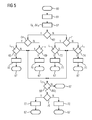
- FIG. 1 a vehicle drive 1 for a (not shown in detail) electric vehicle is shown.
- the vehicle drive 1 comprises as an electrical load by way of example a three-phase electric (drive) motor 2 of the vehicle.
- the vehicle drive 1 further comprises a (MHF) converter 3, which supplies the motor 2 with electrical power from an electrical DC voltage source.
- the DC voltage source in the illustrated example is the (traction) battery 4 (also: high-voltage battery) of the vehicle.
- the converter 3 comprises in the example according to FIG. 1 three submodules 5a, 5b and 5c.
- the converter 3 also includes as a control device a central control unit 6 and also an inductance 7.
- Battery circuit 8 a supply circuit
- Each submodule 5a-5c is in this case connected to two input terminals 9 and 10 in the battery circuit 8.
- each of the submodules 5a-5c is connected in each case via two output terminals 11 and 12 and a load circuit 13 to a respective associated phase winding 14 of the motor 2.
- each submodule 5a-5c has on the input side a half bridge, hereinafter referred to as input bridge 20, and on the load side a single-phase full bridge (H bridge), referred to below as output bridge 21.
- Each submodule 5a-5c furthermore comprises a DC link capacitor 22 in the form of a capacitor, across which a capacitor voltage U Z1 , U Z2 or U Z3 drops.
- the input bridge 20, the output bridge 21 and the DC link capacitance 22 are in this case connected in parallel to one another between a plus rail 23 and a minus rail 24 of a (DC) DC link 25.
- the input bridge 20 has two branches 27 and 28 separated by a center tap 26, from which the branch 27 extends between the center tap 26 and the plus rail 23, and the branch 28 extends between the center tap 26 and the minus rail 24.
- each of the branches 27, 28 is a (semiconductor) switches 29 and 30 each arranged, each of which is formed by a MOSFET.
- the input terminals 9 and 10 of each sub-module 5a-5c are on both sides of the switch 29th connected to the plus rail 23 and the center tap 26.
- the output bridge 21 is formed from two half-bridges 31 and 32, which are connected in parallel to one another between the positive rail 23 and the minus rail 24 of the intermediate circuit 25.
- two semiconductor switches 33 and 34 or 35 and 36 are arranged in each of the two half-bridges 31, 32.
- the switches 33-36 are again preferably formed by MOSFETs.
- a center tap 37 between the semiconductor switches 33 and 34 of the half-bridge 31 is connected to the output terminal 11.
- a center tap 38 between the semiconductor switches 35 and 36 of the half-bridge 32 is connected in accordance with the output terminal 12.
- a battery voltage U B is applied to the converter 3 by the battery 4 via the battery circuit 8.
- a supply current battery current
- I B battery current intensity
- the submodules 5a-5c are switched to supply the phase windings 14 of the motor 2 with electrical energy from the battery 4 alternately to the battery circuit 8.
- the semiconductor switch 29 is opened in the input bridge 20 of the respective submodule 5a-5c to be switched on, so that the intermediate circuit capacitance 22 of this submodule 5a-5c is connected to the battery circuit 8 via the input terminals 9 and 10 and the semiconductor switch 30.
- a time-varying number of submodules 5a-5c are switched on in this way.
- the or each remaining submodule 5a-5c is switched off from the battery circuit 4 by the input terminals 9 and 10 of these submodules 5a-5c being short-circuited by the respectively associated semiconductor switch 29.
- the intermediate circuit capacitance 22 of the respectively connected submodule 5a-5c is charged from the battery circuit 8, so that the intermediate circuit voltage U Z1 -U Z3 dropping across the intermediate circuit capacitance 22 increases.
- the input bridge 20 of each submodule 5a-5c is operated in cooperation with the inductance 7 as a boost converter.
- the semiconductor switch 29 is clocked, switched on and off in temporal change, in particular with a predetermined modulation rate (pulse-pause ratio).
- the second semiconductor switch 30 of the input bridge 20 is preferably always connected in opposition to the semiconductor switch 29.
- the converter 3 can alternatively also be used to regenerate electrical energy into the battery circuit 8.
- the input bridges 20 of the submodules 5a-5c are hereby operated as step-down converters, in that the semiconductor switch 30 of the respective submodule 5a-5c is switched on and off alternately, in particular clocked in turn.
- the semiconductor switch 29 is preferably always driven in opposition to the semiconductor switch 30.
- the gate terminals of these semiconductor switches 29 and 30 are each occupied by the control unit 6 with an input control signal E 1 -E 3 .
- the input control signals E 1 -E 3 are in each case a pulse signal which fluctuates between the values "0" and "1", the respective submodule 5 a - 5 c being switched off by activation with the value "0" (semiconductor switch 29 closed , Semiconductor switch 30 open), and by driving with the value "1" switched (semiconductor switch 29 is opened, semiconductor switch 30 shot) is.
- the Control unit 6 receives in return from the submodules 5a-5c as an input variable in each case a measured value of the intermediate circuit voltage U Z1 -U Z3 .
- the intermediate circuit voltage U Z1 -U Z3 is in each sub-module 5a-5c respectively by means of a transducer 39 ( FIG. 1 ), which supplies the control unit 6 with a proportional to the respective intermediate circuit voltage U Z1 -U Z3 voltage signal.
- control unit 6 receives a measured value of the battery current intensity I B which is generated by a measuring transducer 40 (FIG. FIG. 1 ) tapped in the battery circuit 8 and the control unit 6 is supplied for example in the form of a current-proportional voltage signal.
- the intermediate circuit voltages U Z1 -U Z3 of the submodules 5a-5c are regulated to a respectively assigned voltage setpoint U Z10 , U Z20 and U Z30 .
- the voltage setpoints U Z10 -U Z30 are given in the general application of the inverter 3 according to the invention specifically for each sub-module 5a-5c and can be defined accordingly with different amounts.
- the control unit 6 also regulates the battery current intensity I B.
- control unit 6 a voltage regulation module 41, a downstream of this power control module 42 and the power control module 42 in turn downstream modulator 43rd
- the voltage regulation module 41 is in turn subdivided into a voltage regulator 44, a differential element 45 connected upstream therefrom, and two summation elements 46 and 47 connected in turn.
- the summation element 46 is supplied with the measured values of the intermediate circuit voltages U Z1 -U Z3 in the submodules 5a-5c as input variables.
- the sum voltage deviation .DELTA.U S is supplied as a reference variable to the - suitably designed as a proportional-integral controller (PI controller) - voltage regulator 44.
- PI controller proportional-integral controller
- the voltage regulator 44 determines a current setpoint I B0 and supplies this to the current regulation module 42 as an input variable.
- the current control module 42 is subdivided into a current regulator 48 and an upstream differential element 49.
- the current controller 48 calculates a manipulated variable S, which is supplied to the modulator 43 as an input variable.
- the manipulated variable S corresponds to that voltage, which in total over the Input bridges 20 of the series-connected submodules 5a-5c should drop.
- the current control module 42 has a much lower response time compared to the voltage regulation module 41.
- the current control module 42 can thus effectively regulate fast current fluctuations, while the voltage regulation module 41 is used to adjust the average battery current intensity I B to the changing power requirement of the motor 2.
- the measured values of the intermediate circuit voltages U Z1 -U Z3 and the associated voltage setpoints U Z10 -U Z30 as well as the measured value of the battery current intensity I B are supplied to the modulator 43 as further input variables.
- the modulator 43 generates the respective input control signal E 1 -E 3 for the input bridges 20 of the submodules 5 a - 5 c according to a in FIG. 4 detailed method.
- the modulator 43 separately calculates the voltage deviation of the respective intermediate circuit voltage U Z1 -U Z3 from the assigned voltage setpoint U Z10 -U Z30 for each submodule 5a-5c.
- the modulator 43 sorts the submodules 5a-5c according to the size of the respectively assigned voltage deviation.
- the modulator 43 checks whether the battery current intensity I B and thus the current flow direction in the battery circuit 8 are positive (I B > 0).
- the modulator 43 selects, in a step 54 the one submodule 5a-5c with the minimum voltage deviation (min ⁇ U Z1 -U Z10; U Z2 -U Z20; U Z3 U Z30; ⁇ ), and optionally one or more sub-modules 5a -5c with next larger voltage deviation and determines for each selected submodule 5a-5c an assigned Aus Kunststoffgrad for the clocked control of the input bridge 20, so that the sum of the desired voltages U Z01 -U Z03 of the selected submodules 5a-5c in the time average of the manipulated variable S corresponds.
- the modulator 43 assigns to the submodule 5a-5c with the minimum voltage deviation a greater degree of modulation than optionally further selected submodules 5a-5c with greater voltage deviation.
- the modulator 43 assigns to the submodule 5a-5c with the minimum voltage deviation a Aus confusegrad between 0 and 1, when the manipulated variable S corresponds to a voltage between 0 and the voltage setpoint U Z01 -U Z03 this submodule 5a-5c, while the other submodules assigns the Aus confusegrad 0.
- the modulator 43 assigns to the submodule 5a-5c with the minimum voltage deviation the Aus confusegrad 1 and the submodule 5a-5c with the next larger voltage deviation a Aus confusegrad between 0 and 1.
- the remaining submodule 5a-5c is driven with the modulation level 0.
- the modulator 43 assigns the minimum voltage deviation submodule 5a-5c and the submodule 5a-5c with the next larger voltage deviation in each case the Aus confusegrad 1 and the submodule 5a-5c with the largest voltage deviation a Aus confusegrad between 0 and 1 to.
- the modulator 43 selects in a step 55 the sub-module 5a-5c with the maximum voltage deviation (max ⁇ U Z1 -U Z10 ; U Z2 -U Z20 ; U Z3 U Z30 ; ⁇ ) and possibly one or more sub-modules 5a-5c with the next smallest voltage deviation and determines for each selected sub-module 5a-5c an assigned level of modulation for the control of the input bridge 20, see FIG the sum of the setpoint voltages U Z01 -U Z03 of the selected submodules 5a-5c corresponds to the time average of the manipulated variable S.
- the modulator 43 vice versa analogous to the method step 54 - the submodule 5a-5c with the maximum voltage deviation to a larger Aus confusegrad than optionally further selected submodules 5a-5c with a smaller voltage deviation.
- the modulator 43 In a step 56, the modulator 43 generates in the following clock cycle of the input control signals E 1 -E 3 each a control pulse and a subsequent pulse pause with the determined in step 54 or 55 Aus confusegrad.
- the modulator 43 sets the output levels of the submodules 5a-5c so firmly that 1.6 submodules are switched in the time average in each clock cycle.
- the modulator 43 jumps back to the process start 50 from the process end 57 following the step 56 after every clock cycle, so that the steps 51 to 56 are repeated cyclically.
- the submodules 5a-5c to be switched on are selected again by the modulator 43 for each clock cycle of the input control signals E 1 -E 3 .
- At least one submodule 5a-5c is always connected to the battery circuit 8 by the modulator 43 in the event of a negative current flow in the battery circuit 8, whose intermediate circuit capacitance 22 has the highest state of charge, at least relatively, so that this intermediate circuit capacitance is preferably discharged into the battery circuit 8 ,
- the battery power level I B is adjusted as needed by the control unit 6 by adjusting the Aus Kunststoffgrades the input control signals E 1 -E 3, while compensating for rapid power fluctuations.
- the explicit determination of the voltage deviations according to step 51 can optionally be omitted.
- the submodules 5a-5c are sorted immediately after the amount of the intermediate circuit voltages U Z1 -U Z3 , step 52.
- step 54 is always at least the submodule 5a-5c with the smallest intermediate circuit voltage U Z1 -U Z3 is selected (min ⁇ U Z1 ; U Z2 ; U Z3 ⁇ ), while in step 55 at least the submodule 5a-5c with the largest intermediate circuit voltage U Z1 -U Z3 is always selected becomes (max ⁇ U Z1 ; U Z2 ; U Z3 ⁇ ).
- the submodules 5a-5c to be connected to the battery circuit 8 are not periodically re-determined by the modulator 43, but only when a corresponding requirement is established.
- the modulator 43 orders according to FIG. 5 in a first step 61, the submodules 5a-5c in turn according to the size of the respectively assigned intermediate circuit voltage U Z1 -U Z3 .
- the modulator 43 calculates the voltage that actually drops across the series-connected input bridges 20 of the sub-modules 5a-5c.
- the modulator 43 checks whether the Voltage deviation .DELTA.U E is positive (.DELTA.U E > 0), that is, whether the effective voltage U E the setpoint below S (U E ⁇ S).
- the modulator 43 checks in step 64 whether the battery current intensity I B and thus the current flow direction in the battery circuit 8 are positive (I B > 0).
- the modulator 43 selects in a step 65 from the switched-off submodules 5a-5c that submodule 5a-5c with the smallest intermediate circuit voltage U Z1 -U Z3 . Furthermore, the modulator 43 checks whether the absolute value of the voltage deviation ⁇ U E exceeds a first switching value L 1 (
- the modulator 43 in a step 66 switches on this selected submodule 5a-5c and jumps to the process end 67. Otherwise (N), the modulator 43 jumps to a step 68.
- the modulator 43 in step 66 in other words, the (previously switched off) submodule 5a-5c with the smallest intermediate circuit voltage U Z1 -U Z3 , when the Absolute amount of the voltage deviation .DELTA.U E exceeds half the DC link voltage U Z1 -U Z3 this sub-module 5a-5c.
- the modulator 43 selects in a step 69 from the switched-off sub-modules 5a-5c that submodule 5a-5c with the largest intermediate circuit voltage U Z1 -U Z3 . Again, the modulator 43 checks whether the absolute value of the voltage deviation .DELTA.U E exceeds the switching value L 1 (
- the modulator 43 in a step 70 switches on this selected submodule 5a-5c and jumps to the process end 67. Otherwise (N) the modulator 43 jumps to the step 68.
- the modulator 43 in step 70 in other words, the (previously switched off) submodule 5a-5c with the largest intermediate circuit voltage U Z1 -U Z3 , when the Absolute amount of the voltage deviation .DELTA.U E exceeds half the DC link voltage U Z1 -U Z3 this sub-module 5a-5c.
- step 63 test N
- the modulator 43 checks in a step 71 again, if the battery current I B, and thus the direction of current flow in the battery circuit 8 are positive (I B > 0).
- the modulator 43 selects in a step 72 from the connected submodules 5a-5c that submodule 5a-5c having the largest intermediate circuit voltage U Z1 -U Z3 . Furthermore, the modulator 43 checks whether the absolute value of the voltage deviation ⁇ U E exceeds the switching value L 1 (
- the modulator 43 switches off in a step 73 this selected sub-module 5a-5c and jumps to the process end 67. Otherwise (N) the modulator 43 jumps to a step 68.
- the modulator 43 switches in step 73 in other words the (previously switched on) submodule 5a-5c with the largest DC link voltage U Z1 -U Z3 , if the absolute value of the voltage deviation ⁇ U E exceeds half the intermediate circuit voltage U Z1 -U Z3 of this sub-module 5a-5c.
- the modulator 43 selects in a step 74 from the connected sub-modules 5a-5c that submodule 5a-5c with the smallest intermediate circuit voltage U Z1 -U Z3 .
- the modulator 43 again checks whether the absolute value of the voltage deviation ⁇ U E exceeds the switching value L 1 (
- the modulator 43 shuts off this selected submodule 5a-5c in a step 75 and jumps to the end of the method 67. Otherwise (N), the modulator 43 jumps to step 68.
- the modulator 43 switches off in step 75, in other words, the (previously switched on) submodule 5a-5c with the smallest intermediate circuit voltage U Z1 -U Z3 , if the Absolute amount of the voltage deviation .DELTA.U E exceeds half the DC link voltage U Z1 -U Z3 this sub-module 5a-5c.
- the modulator 43 jumps to the end of the process 67.
- the modulator exchanges one of the connected submodules 5a-5c with one of the switched-off submodules 5a-5c.
- the modulator 43 first checks in a step 76 again whether the battery current intensity I B and thus the current flow direction in the battery current circuit 8 are positive (I B > 0).
- the modulator 43 switches off the (previously switched on) submodule 5a-5c with the largest intermediate circuit voltage U Z1 -U Z3 in a step 77 and the (previously switched off) submodule 5a-5c with the smallest intermediate circuit voltage U Z1 -U Z3 and jumps to the end of the process 67.
- the modulator 43 switches in a step 78 the (previously switched on) submodule 5a-5c with the smallest intermediate circuit voltage U Z1 -U Z3 and the (previously switched off) submodule 5a-5c with the largest intermediate circuit voltage U Z1 -U Z3 and also jumps to the end of the process 67.
- the method according to FIG. 5 is repeated continuously by the modulator 43.
- the modulator 43 In the course of the case distinction made in steps 63 to 75, the modulator 43 always switches submodules 5a-5b on or off, if this makes it possible to bring the effective voltage U E into better agreement with the manipulated variable S, whereby submodule 5a-5c to be switched off such that the intermediate circuit voltages U Z1 -U Z3 are matched to one another in the best possible way.
- the modulator 43 alternates between the submodules 5a-5c in such a way that the DC link voltages U Z1 -U Z3 are matched to one another in the best possible way.
- the modulator 43 alternates between the submodules 5a-5c in such a way that the DC link voltages U Z1 -U Z3 are matched to one another in the best possible way.
- the modulator 43 switches in accordance with the method FIG. 5 the submodules 5a-5c not in a periodic clock cycle up or down, but only when needed - hence, if in one of the steps 65, 69, 72, 74 or 68, the exceeding of the respective switching value L 1 or L 2 is detected.
- the control unit 6 is formed in a preferred embodiment by a microcontroller, in which the functionality for performing the above with reference to the 3 to 5 described control method is implemented by software.
- the voltage regulation module 41, the current regulation module 42 and the modulator 43 are formed by software components that use the hardware of the microcontroller to generate the input control signals E 1 -E 3 .
- the inverter 3 may include more (or less) than the three sub-modules 5a-5c.
- the inverter 3 can be used in particular for supplying a plurality of independent loads.
- the converter 3 drives four electric motors, one of which is assigned to one wheel of the vehicle.
- the converter 3 comprises, for example, a submodule for each phase winding of each electric motor.
Abstract
Description
Die Erfindung bezieht sich auf einen Modularen Hochfrequenz-Umrichter. Die Erfindung bezieht sich des Weiteren auf ein Verfahren zum Betrieb eines solchen.The invention relates to a modular high-frequency converter. The invention further relates to a method of operating such.
Eine Umrichterschaltung der vorstehend genannten Art ist in der Veröffentlichung
Der bekannte Modulare Hochfrequenz-Umrichter (kurz MHF-Umrichter) ist zum Umwandeln einer Gleichspannung aus einer Traktionsbatterie des Fahrzeugs in mehrere Wechselspannungen vorgesehen. Die einzelnen Wechselspannungen werden dabei durch mehrere Submodule erzeugt, die in Reihe in den Versorgungsstromkreis der Traktionsbatterie geschaltet sind. Jedes Submodul ist dabei eingangsseitig über eine einphasige Halbbrücke mit dem Versorgungsstromkreis verbunden. Zur Erzeugung der Wechselspannung weist jedes Submodul ausgangsseitig eine einphasige Vollbrücke (H-Brücke) auf, die über einen Laststromkreis mit einer Phasenwicklung des Antriebsmotors des Fahrzeugs verschaltet ist. Submodulintern sind die eingangsseitige Halbbrücke und die Vollbrücke zusammen mit einer Zwischenkreiskapazität in einem (Gleichspannungs-)Zwischenkreis parallelgeschaltet.The well-known modular high-frequency inverter (MHF inverter for short) is provided for converting a DC voltage from a traction battery of the vehicle into a plurality of AC voltages. The individual AC voltages are generated by a plurality of sub-modules, which are connected in series in the supply circuit of the traction battery. Each submodule is connected on the input side via a single-phase half-bridge to the supply circuit. To generate the alternating voltage, each submodule has on the output side a single-phase full bridge (H bridge), which is connected via a load circuit to a phase winding of the drive motor of the vehicle. Submoduletern the input side half-bridge and the full bridge are connected in parallel with a DC link capacitance in a (DC) DC link.
Im Normalbetrieb (Antriebsmodus) des MHF-Umrichters, in dem über die Submodule des Umrichters elektrische Leistung aus dem Versorgungsstromkreis in den jeweiligen Laststromkreis transportiert wird, werden die Eingangshalbbrücken der Submodule in Zusammenwirkung mit einer im Versorgungsstromkreis angeordneten Induktivität als Hochsetzsteller betrieben. Hierzu werden üblicherweise die Submodule in regelmäßig alternierendem Wechsel auf den Versorgungsstromkreis aufgeschaltet. Die eingangsseitigen Halbbrücken werden zu diesem Zweck üblicherweise mit periodischen Trägersignalen angesteuert, die um gleiche Phasenwinkel versetzt sind. Infolge dieser Ansteuerung wird die Zwischenkreiskapazität des jeweils aufgeschalteten Submoduls für die Dauer eines Aufschaltpulses in den Versorgungsstromkreis geschaltet.During normal operation (drive mode) of the MHF converter, in which electrical power is transported from the supply circuit into the respective load circuit via the submodules of the converter, the input half bridges of the submodules are operated as a step-up converter in cooperation with an inductance arranged in the supply circuit. For this purpose, usually the submodules are switched to the supply circuit in a regularly alternating change. The input half bridges are usually controlled for this purpose with periodic carrier signals, which are offset by the same phase angle. As a result of this control, the DC link capacitance of each submodule is switched for the duration of a Aufschaltpulses in the supply circuit.
Zusätzlich zu dem Antriebsmodus können die eingangsseitigen Halbbrücken der Submodule in einem Rückspeisemodus betrieben werden, in dem elektrische Leistung aus dem Laststromkreis über das jeweils zugehörige Submodul in den Versorgungsstromkreis zurückgespeist wird. Die eingangsseitigen Halbbrücken der Submodule werden hierzu als Tiefsetzsteller betrieben.In addition to the drive mode, the input half bridges of the submodules can be operated in a regenerative mode in which electrical power is fed back from the load circuit via the associated submodule into the supply circuit. The input half bridges of the submodules are operated for this purpose as a buck converter.
Die Zwischenkreisspannungen der Submodule werden für jedes Submodul individuell durch Variation der Dauer des jeweiligen Aufschaltpulses geregelt.The DC link voltages of the submodules are controlled individually for each submodule by varying the duration of the respective switch-on pulse.
Der Erfindung liegt die Aufgabe zugrunde, einen MHF-Umrichter und ein Verfahren zu dessen Betrieb zu verbessern.The invention has for its object to improve a MHF inverter and a method for its operation.
Bezüglich des Verfahrens wird diese Aufgabe erfindungsgemäß gelöst durch die Merkmale des Anspruchs 1. Bezüglich des MHF-Umrichters wird die Aufgabe erfindungsgemäß gelöst durch die Merkmale des Anspruchs 9. Vorteilhafte und teils für sich gesehen erfinderische Ausgestaltungsformen und Weiterentwicklungen der Erfindung sind in den Unteransprüchen und der nachfolgenden Beschreibung dargelegt.With regard to the method, this object is achieved according to the invention by the features of claim 1. With respect to the MHF inverter, the object is achieved by the features of
Die Erfindung geht aus von einem MHF-Umrichter, der mehrere Submodule umfasst. Die Submodule werden hierbei bestimmungsgemäß eingangsseitig in Reihe über eine Induktivität in einen aus einer Gleichspannungsquelle gespeisten Versorgungsstromkreis geschaltet. Jedes Submodul weist eingangsseitig eine Halbbrücke (nachfolgend Eingangsbrücke) auf, mit der das Submodul in den Versorgungsstromkreis geschaltet ist. Ausgangsseitig weist jedes Submodul eine mindestens einphasige Vollbrücke (nachfolgend Ausgangsbrücke) auf, mit der das Submodul über einen Laststromkreis mit einer anzusteuernden Last verbunden ist. Jedes Submodul weist des Weiteren einen (Gleichspannungs-)Zwischenkreis auf, in welchem die Eingangsbrücke und die Ausgangsbrücke parallelgeschaltet sind. In den Zwischenkreis ist zudem - in Parallelschaltung zu der Eingangsbrücke und der Ausgangsbrücke - eine Zwischenkreiskapazität geschaltet.The invention is based on a MHF converter comprising a plurality of submodules. In this case, the submodules are purposefully connected on the input side in series via an inductance into a supply circuit fed from a DC voltage source. Each submodule has on the input side a half bridge (hereinafter input bridge) with which the submodule is connected in the supply circuit. On the output side Each submodule has an at least single-phase full bridge (hereinafter output bridge) to which the submodule is connected via a load circuit to a load to be controlled. Each submodule also has a (DC) DC link, in which the input bridge and the output bridge are connected in parallel. In addition, a DC link capacitance is connected in the DC link in parallel with the input bridge and the output bridge.
Der MHF-Umrichter ist insbesondere zum Einsatz in dem Fahrzeugantrieb eines Elektrofahrzeugs vorgesehen. Als Gleichstromquelle für den Versorgungsstromkreis ist in diesem Anwendungsfall die Traktionsbatterie (Hochvoltbatterie) des Fahrzeugs vorgesehen. Bei der an das Submodul ausgangsseitig anzuschließenden Last handelt es sich hier insbesondere um einen Elektromotor oder um eine Phasenwicklung eines solchen. Vorzugsweise ist dabei jeder Phasenwicklung des Elektromotors ein eigenes Submodul zugeordnet. Alternativ hierzu können im Rahmen der Erfindung allerdings mehrere Phasenwicklungen eines mehrphasigen Elektromotors an ein gemeinsames Submodul angeschlossen werden. Die Ausgangsbrücke ist in diesem Fall durch eine entsprechend mehrphasige Vollbrücke gebildet. In einem speziellen Anwendungsfall der Erfindung können mehrere Elektromotoren - die beispielsweise zum jeweils selektiven Antrieb verschiedener Räder des Fahrzeugs dienen - parallel zueinander durch verschiedene Submodule des MHF-Umrichters angesteuert werden. Die Zwischenkreiskapazität eines jeden Submoduls ist jeweils insbesondere durch einen oder mehrere Kondensatoren gebildet.The MHF converter is provided in particular for use in the vehicle drive of an electric vehicle. As a DC power source for the supply circuit, the traction battery (high-voltage battery) of the vehicle is provided in this application. The load to be connected to the output side of the submodule is, in particular, an electric motor or a phase winding of such. Preferably, each phase winding of the electric motor is assigned its own submodule. Alternatively, however, a plurality of phase windings of a multi-phase electric motor can be connected to a common submodule within the scope of the invention. The output bridge is formed in this case by a corresponding multi-phase full bridge. In a specific application of the invention, a plurality of electric motors - which serve, for example, for respectively selectively driving different wheels of the vehicle - can be controlled in parallel to each other by various submodules of the MHF converter. The DC link capacitance of each submodule is in each case formed in particular by one or more capacitors.
Im Zuge des Verfahrens werden die Zwischenkreiskapazitäten der Submodule im Wechsel mittels der jeweils zugeordneten Eingangsbrücke in den Versorgungsstromkreis geschaltet. Die Schaltung der Zwischenkreiskapazität eines Submoduls in den Versorgungsstromkreis ist nachfolgend abkürzend als "Aufschaltung" des jeweiligen Submoduls auf den Versorgungsstromkreis bezeichnet. Das oder jedes Submodul, dessen Zwischenkreiskapazität in den Versorgungsstromkreis geschaltet wird, ist nachfolgend als "aufgeschaltetes Submodul" bezeichnet. In der Regel sind zu jedem Zeitpunkt stets mehrere Submodule gleichzeitig auf den Versorgungsstromkreis aufgeschaltet.In the course of the process, the DC link capacitances of the submodules are alternately switched to the supply circuit by means of the respectively assigned input bridge. The circuit of the DC link capacitance of a submodule in the supply circuit is abbreviated below as "connection" of the respective submodule referred to the supply circuit. The or each submodule, its DC link capacity is switched into the supply circuit is hereinafter referred to as "switched submodule". As a rule, several submodules are always connected to the supply circuit at the same time.
Verfahrensgemäß wird nun die über der jeweiligen Zwischenkreiskapazität eines jeden Submoduls abfallende Zwischenkreisspannung gemessen. Das oder jedes aufzuschaltende Submodul wird dabei erfindungsgemäß nach Maßgabe der Spannungsabweichung der zugehörigen Zwischenkreisspannung von einem vorgegebenen Spannungssollwert ausgewählt. Insbesondere werden in bevorzugter Ausführung des Verfahrens stets zumindest dasjenige Submodul mit der maximalen Spannungsabweichung (insbesondere mit der größten positiven Spannungsabweichung) oder zumindest dasjenige Submodul mit der minimalen Spannungsabweichung (insbesondere mit der größten negativen Spannungsabweichung) auf den Versorgungsstromkreis aufgeschaltet. Die Spannungsabweichung wird dabei als positiv gewertet, wenn die gemessene Zwischenkreisspannung den Spannungssollwert überschreitet. Die Spannungsabweichung wird entsprechend als negativ gewertet, wenn die gemessene Zwischenkreisspannung den Spannungssollwert unterschreitet.According to the method, the DC link voltage dropping across the respective DC link capacitance of each submodule is measured. The or each aufzuschaltende submodule is selected according to the invention in accordance with the voltage deviation of the associated DC link voltage from a predetermined voltage setpoint. In particular, in a preferred embodiment of the method always at least that submodule with the maximum voltage deviation (in particular with the largest positive voltage deviation) or at least that submodule with the minimum voltage deviation (in particular with the largest negative voltage deviation) is applied to the supply circuit. The voltage deviation is evaluated as positive if the measured intermediate circuit voltage exceeds the voltage setpoint. The voltage deviation is evaluated as negative if the measured intermediate circuit voltage falls below the voltage setpoint.
Durch die Auswahl der aufzuschaltenden Submodule nach Maßgabe der Spannungsabweichung der jeweiligen Zwischenkreisspannung kann auf besonders einfache, aber effektive Weise eine Vergleichmäßigung des Leistungsflusses in dem Versorgungskreis erzielt werden. Zudem kann die Anzahl der Schaltprozesse der Eingangsbrücken reduziert werden. Die Belastung der Umrichterkomponenten, insbesondere der Halbleiterschalter der Eingangsbrücken kann somit reduziert werden.By selecting the aufzuschaltenden submodule in accordance with the voltage deviation of the respective DC link voltage can be achieved in a particularly simple, but effective way equalization of the power flow in the supply circuit. In addition, the number of switching processes of the input bridges can be reduced. The load on the converter components, in particular the semiconductor switches of the input bridges can thus be reduced.
Das Verfahren ermöglicht dabei insbesondere, den Spannungssollwert für jedes Submodul individuell vorzugeben. Somit können die Submodule im Rahmen der Erfindung wahlweise auf gleiche oder unterschiedliche Zwischenkreisspannungen geregelt werden. Insbesondere für den letzteren Fall wird im Zuge des Verfahrens vorzugsweise die Spannungsabweichung für jedes Submodul durch Vergleich der jeweils gemessenen Zwischenkreisspannung mit dem zugehörigen Spannungssollwert explizit berechnet. Sofern allerdings für alle Submodule der Spannungssollwert einheitlich (und somit gleich) vorgegeben ist, wird die Spannungsabweichung vorzugsweise nicht explizit berechnet. Vielmehr werden in diesem Fall die Zwischenkreisspannungen unmittelbar miteinander verglichen, da sich der Unterschied der Spannungsabweichungen bei gleichen Spannungssollwerten erkanntermaßen direkt im Unterschied der gemessenen Zwischenkreisspannungen äußert.In particular, the method makes it possible to specify the voltage setpoint for each submodule individually. Thus, the submodules can be controlled in the context of the invention optionally to the same or different DC link voltages. Especially in the latter case, in the course of the method, the voltage deviation is preferably for each Submodule calculated by comparing the measured DC link voltage with the associated voltage setpoint explicitly. If, however, the voltage setpoint is uniform (and therefore the same) for all submodules, the voltage deviation is preferably not explicitly calculated. Rather, in this case, the DC link voltages are compared directly with each other, since the difference of the voltage deviations at the same voltage setpoints is known to be expressed directly in the difference between the measured DC link voltages.
In einer verfeinerten Verfahrensvariante wird zusätzlich zu den Zwischenkreisspannungen die Stromrichtung des in dem Versorgungsstromkreis fließenden Stroms bestimmt und bei der Auswahl des aufzuschaltenden Submoduls berücksichtigt. Dabei wird vorzugsweise stets zumindest dasjenige Submodul mit der minimalen (insbesondere größten negativen) Spannungsabweichung auf den Versorgungsstromkreis aufgeschaltet, wenn die Stromrichtung positiv ist. Bei negativer Stromrichtung wird dagegen stets zumindest dasjenige Submodul mit der maximalen (insbesondere größten positiven) Spannungsabweichung auf den Versorgungsstromkreis aufgeschaltet.In a refined method variant, in addition to the intermediate circuit voltages, the current direction of the current flowing in the supply circuit current is determined and taken into account in the selection of the aufzuschaltenden submodule. In this case, preferably always at least that submodule with the minimum (in particular largest negative) voltage deviation is applied to the supply circuit when the current direction is positive. In the negative current direction, however, always at least that submodule with the maximum (in particular largest positive) voltage deviation is switched to the supply circuit.
Als Stromfluss mit "positiver Stromrichtung" wird hierbei im Sinne der technischen Stromrichtungsdefinition ein von dem Plus-Pol auf den Minus-Pol der Gleichspannungsquelle gerichteter Stromfluss gewertet. Als "negativ" wird umgekehrt ein von dem Minus-Pol auf den Plus-Pol der Gleichspannungsquelle gerichteter Stromfluss gewertet.As a current flow with "positive current direction", a current flow directed from the plus pole to the minus pole of the direct voltage source is evaluated here in the sense of the technical current direction definition. Conversely, as negative, a current flow directed by the negative pole to the positive pole of the DC voltage source is evaluated.
Die Anpassung der Zwischenkreisspannungen wird somit bei der vorstehend beschriebenen Verfahrensvariante stromrichtungsabhängig sowohl durch aktive Ladung von teilentleerten Zwischenkreiskapazitäten als auch durch aktive Entladung von überladenen Zwischenkreiskapazitäten vorgenommen, und ist hierdurch besonders effektiv.The adaptation of the DC link voltages is thus carried out in the process variant described above depending on the direction of both active charge of partially depleted DC link capacitances and by active discharge of overloaded DC link capacitances, and is thereby particularly effective.
In zweckmäßiger Ausführung des Verfahrens wird die Eingangsbrücke des aufgeschalteten Submoduls mittels eines Eingangssteuersignals getaktet angesteuert. Das Eingangssteuersignal ist zweckmäßigerweise durch ein Pulssignal gebildet, das in jedem Taktzyklus vorgegebener Taktdauer jeweils einen Puls und eine Pulspause mit einstellbarem Aussteuergrad (auch als Puls-Pausen-Verhältnis oder Duty-Cycle bezeichnet) aufweist.In an expedient embodiment of the method, the input bridge of the connected submodule is clocked by means of an input control signal. The input control signal is expediently formed by a pulse signal which has one pulse and one pulse pause with adjustable modulation rate (also referred to as pulse-pause ratio or duty cycle) in each clock cycle of predetermined cycle duration.
Die Variation des Aussteuergrades ermöglicht hierbei im Zuge des erfindungsgemäßen Verfahrens, nicht nur die einzelnen Zwischenkreisspannungen, sondern unabhängig hiervon auch den durch den Versorgungsstromkreis fließenden Strom (Versorgungsstrom) bedarfsgerecht zu regeln. Für die Spannungsregelung wird vorzugsweise die Summenspannung ermittelt, die durch die Summe der gemessenen Zwischenkreisspannungen aller Submodule gegeben ist. Aus der Abweichung dieser Summenspannung von der Summe der Spannungssollwerte wird dabei ein Stromsollwert für den Versorgungsstrom abgeleitet. Dieser Stromsollwert wird wiederum als Eingangsgröße für eine nachgeschaltete Stromregelung herangezogen. Im Zuge dieser Stromregelung wird der Versorgungsstrom durch Auf- und Abschalten von Submodulen, und somit durch Variation der über den Submodulen im Versorgungsstromstromkreis in Summe abfallenden Spannung (Effektivspannung) geregelt.The variation of Aussteuergrades allows this in the course of the process according to the invention, not only the individual DC link voltages, but independently also to regulate the current flowing through the supply circuit (supply current) as needed. For the voltage regulation, the sum voltage is preferably determined, which is given by the sum of the measured intermediate circuit voltages of all submodules. From the deviation of this sum voltage from the sum of the voltage setpoints, a current setpoint for the supply current is derived. This current setpoint is in turn used as input for a downstream current control. In the course of this current regulation, the supply current is regulated by switching on and off submodules, and thus by varying the voltage drop across the submodules in the supply current circuit (effective voltage).
In einer einfach realisierbaren Verfahrensvariante wird für jeden Taktzyklus der Eingangssteuersignale das oder jedes aufzuschaltende Submodul nach Maßgabe der Spannungsabweichungen neu ausgewählt. Es wird also insbesondere für jeden Taktzyklus erneut - nach einer der vorstehend beschriebenen Ausgestaltungsformen des Verfahrens - zumindest dasjenige Submodul mit der maximalen (insbesondere größten positiven) oder minimalen (insbesondere größten negativen) Spannungsabweichung ermittelt auf den Versorgungsstromkreis aufgeschaltet.In an easily implementable method variant, the or each submodule to be switched on is selected anew according to the voltage deviations for each clock cycle of the input control signals. Thus, in particular for each clock cycle, once again, according to one of the embodiments of the method described above, at least that submodule with the maximum (in particular the largest positive) or minimum (in particular largest negative) voltage deviation determined is applied to the supply circuit.
In einer alternativen Verfahrensvariante wird der Wechsel zwischen den aufzuschaltenden Submodulen in Abhängigkeit der vorstehend eingeführten Effektivspannung vorgenommen, also in Abhängigkeit der Spannung, die in Summe über den Eingangskreisen der in Reihe geschalteten Submodule abfällt. Submodule werden dabei nur dann auf- oder abgeschaltet, wenn diese Effektivspannung - zu der nur die aufgeschalteten Submodule einen von Null verschiedenen Beitrag liefern - von einem vorgegebenen Sollwert um mehr als einen vorgegebenen Schaltwert abweicht. Dieser Schaltwert wird dabei in zweckmäßiger Ausgestaltung des Verfahrens variabel gewählt, so dass er der Hälfte (dem halben Betrag) der Zwischenkreisspannung des auf-oder abzuschaltenden Submoduls entspricht. Der Sollwert wird zweckmäßigerweise aus der von der vorstehend beschriebenen Stromregelung ausgegebenen Stellgröße abgeleitet.In an alternative variant of the method, the change between the submodules to be switched on is made as a function of the effective voltage introduced above, ie in Dependence of voltage, which drops in total across the input circuits of the series-connected submodules. Submodules are only switched on or off when this effective voltage - to which only the connected submodules supply a nonzero contribution - deviates from a predetermined setpoint by more than a predetermined switching value. This switching value is variably selected in an expedient embodiment of the method, so that it corresponds to half (half the amount) of the intermediate circuit voltage of the submodule to be switched on or off. The setpoint is expediently derived from the control variable output by the current control described above.
In zweckmäßiger Ausgestaltung der Erfindung führt der MHF-Umrichter das erfindungsgemäße Verfahren automatisch durch. Er umfasst hierzu eine Steuereinrichtung, die schaltungs-und/oder programmtechnisch zur Durchführung des Verfahrens, insbesondere in einer der vorstehend beschriebenen Ausführungsvarianten eingerichtet ist. Die Steuereinrichtung umfasst dabei insbesondere einen Mikrocontroller, in dem ein das Verfahren in Betrieb des Umrichters automatisch durchführendes Steuerprogramm (Firmware) lauffähig implementiert ist. Alternativ oder zusätzlich kann die Steuereinrichtung im Rahmen der Erfindung allerdings auch mindestens einen nichtprogrammierbaren Hardware-Schaltkreis (z.B. einen ASIC) umfassen, in dem die Funktion zur automatischen Durchführung des Verfahrens oder eines Teils davon mit schaltungstechnischen Mitteln implementiert ist.In an expedient embodiment of the invention, the MHF converter carries out the method according to the invention automatically. For this purpose, it comprises a control device which is set up in circuit and / or program technology for carrying out the method, in particular in one of the embodiment variants described above. In this case, the control device in particular comprises a microcontroller in which a control program (firmware) automatically executing the method during operation of the converter is implemented in an executable manner. Alternatively or additionally, however, the control device in the invention may also comprise at least one non-programmable hardware circuit (for example an ASIC) in which the function for automatically carrying out the method or a part thereof is implemented by means of circuitry.
Die Steuereinrichtung kann im Rahmen der Erfindung durch eine einzige, alle Umrichtermodule gemeinsam ansteuernde (Zentral-) Steuereinheit gebildet sein, beispielsweise also durch einen einzigen Mikrocontroller. Alternativ oder zusätzlich hierzu kann die Steuereinrichtung im Rahmen der Erfindung aber auch ganz oder teilweise dezentral strukturiert sein, indem jedem Umrichtermodul (zumindest auch) eine eigene Steuereinheit zugeordnet ist.In the context of the invention, the control device can be formed by a single (central) control unit which controls all converter modules in common, for example by a single microcontroller. As an alternative or in addition to this, however, the control device can also be completely or partially decentrally structured in the context of the invention in that each drive module is (at least) also assigned its own control unit.
Nachfolgend wird ein Ausführungsbeispiel der Erfindung anhand einer Zeichnung näher erläutert. Darin zeigen:
- FIG 1
- in einem schematisch vereinfachten elektronischen Schaltbild einen MHF-Umrichter mit drei in Reihe geschalteten Submodulen, wobei jedes der Submodule eine eingangsseitige Halbbrücke (Eingangsbrücke), eine ausgangsseitige einphasige Vollbrücke (Ausgangsbrücke) und einen (Gleichspannungs-)Zwischenkreis mit einer Zwischenkreiskapazität umfasst, sowie mit einer Steuereinheit zur Ansteuerung der Submodule,
- FIG 2
- in vergrößerter Darstellung eines der Submodule gemäß
FIG 1 , - FIG 3
- in einem schematischen Blockschaltbild die Steuereinheit gemäß
FIG 1 , - FIG 4
- in einem Flussdiagramm ein von einem Modulator der Steuereinheit zur Ansteuerung der Eingangsbrücken der Submodule durchgeführtes Verfahren, und
- FIG 5
- in Darstellung gemäß
FIG 4 eine alternative Ausführungsform des Verfahrens.
- FIG. 1
- in a schematically simplified electronic circuit diagram, a MHF inverter with three submodules connected in series, each of the submodules an input side half-bridge (input bridge), an output side single-phase full bridge (output bridge) and a (DC) DC link with a DC link capacity includes, and with a Control unit for controlling the submodules,
- FIG. 2
- in an enlarged view of one of the submodules according to
FIG. 1 . - FIG. 3
- in a schematic block diagram, the control unit according to
FIG. 1 . - FIG. 4
- in a flowchart, a method performed by a modulator of the control unit for controlling the input bridges of the submodules, and
- FIG. 5
- in illustration according to
FIG. 4 an alternative embodiment of the method.
Einander entsprechende Teile und Größen sind in allen Figuren stets mit gleichen Bezugszeichen versehen.Corresponding parts and sizes are always provided with the same reference numerals in all figures.
In
Der Fahrzeugantrieb 1 umfasst des Weiteren einen (MHF-) Umrichter 3, der den Motor 2 mit elektrischer Leistung aus einer elektrischen Gleichspannungsquelle versorgt. Bei der Gleichspannungsquelle handelt es sich in dem dargestellten Beispiel um die (Traktions-)Batterie 4 (auch: Hochvoltbatterie) des Fahrzeugs.The vehicle drive 1 further comprises a (MHF) converter 3, which supplies the motor 2 with electrical power from an electrical DC voltage source. The DC voltage source in the illustrated example is the (traction) battery 4 (also: high-voltage battery) of the vehicle.
Der Umrichter 3 umfasst im Beispiel gemäß
Die Induktivität 7, die schaltungstechnisch insbesondere durch eine Spule realisiert ist, und die drei Submodule 5a-5c sind in Reihenschaltung über einen Versorgungsstromkreis (nachfolgend als Batteriestromkreis 8 bezeichnet) mit der Batterie 4 verbunden. Jedes Submodul 5a-5c ist hierbei mit zwei Eingangsklemmen 9 und 10 in den Batteriestromkreis 8 geschaltet.The inductance 7, which is realized in terms of circuitry in particular by a coil, and the three submodules 5 a - 5 c are connected in series via a supply circuit (hereinafter referred to as battery circuit 8) to the battery 4. Each submodule 5a-5c is in this case connected to two
Lastseitig ist jedes der Submodule 5a-5c jeweils über zwei Ausgangsklemmen 11 und 12 und einen Lastromkreis 13 an eine jeweils zugeordnete Phasenwicklung 14 des Motors 2 angeschlossen.On the load side, each of the submodules 5a-5c is connected in each case via two
Eines der identisch aufgebauten Submodule 5a-5c ist in
Die Eingangsbrücke 20 weist zwei durch einen Mittelabgriff 26 getrennte Zweige 27 und 28 auf, von denen sich der Zweig 27 zwischen dem Mittelabgriff 26 und der Plus-Schiene 23, und der Zweig 28 zwischen dem Mittelabgriff 26 und der Minus-Schiene 24 erstreckt. In jedem der Zweige 27, 28 ist je ein (Halbleiter-)Schalter 29 bzw. 30 angeordnet, der jeweils durch einen MOSFET gebildet ist. Die Eingangsklemmen 9 und 10 eines jeden Submoduls 5a-5c sind beidseitig des Schalters 29 mit der Plus-Schiene 23 bzw. mit dem Mittelabgriff 26 verschaltet.The
Die Ausgangsbrücke 21 ist gebildet aus zwei Halbbrücken 31 und 32, die parallel zueinander zwischen die Plus-Schiene 23 und die Minus-Schiene 24 des Zwischenkreises 25 geschaltet sind. In jeder der beiden Halbbrücken 31, 32 sind wiederum zwei Halbleiterschalter 33 und 34 bzw. 35 und 36 angeordnet. Die Schalter 33-36 sind wiederum vorzugsweise durch MOSFETs gebildet.The
Ein Mittelabgriff 37 zwischen den Halbleiterschaltern 33 und 34 der Halbbrücke 31 ist mit der Ausgangsklemme 11 verschaltet. Ein Mittelabgriff 38 zwischen den Halbleiterschaltern 35 und 36 der Halbbrücke 32 ist entsprechend mit der Ausgangsklemme 12 verschaltet.A
Im Betrieb des Umrichters 3 wird durch die Batterie 4 über den Batteriestromkreis 8 eine Batteriespannung UB an den Umrichter 3 angelegt. Unter Wirkung der Batteriespannung UB fließt in dem Batteriestromkreis 8 ein Versorgungsstrom (Batteriestrom) mit einer Batteriestromstärke IB.During operation of the converter 3, a battery voltage U B is applied to the converter 3 by the battery 4 via the battery circuit 8. Under the action of the battery voltage U B , a supply current (battery current) flows in the battery circuit 8 with a battery current intensity I B.
In einem Antriebsmodus des Umrichters 3 werden die Submodule 5a-5c zur Speisung der Phasenwicklungen 14 des Motors 2 mit elektrischer Energie aus der Batterie 4 im Wechsel auf den Batteriestromkreis 8 aufgeschaltet. Hierzu wird der Halbleiterschalter 29 in der Eingangsbrücke 20 des jeweils aufzuschaltenden Submoduls 5a-5c geöffnet, so dass die Zwischenkreiskapazität 22 dieses Submoduls 5a-5c über die Eingangsklemmen 9 und 10 und den Halbleiterschalter 30 in den Batteriestromkreis 8 geschaltet ist. Im Regelfall werden auf diese Weise eine zeitlich wechselnde Anzahl von Submodulen 5a-5c aufgeschaltet. Das oder jedes übrige Submodul 5a-5c ist dagegen von dem Batteriestromkreis 4 abgeschaltet, indem die Eingangsklemmen 9 und 10 dieser Submodule 5a-5c durch den jeweils zugehörigen Halbleiterschalter 29 kurzgeschlossen sind. Bei positiver Stromflussrichtung des in dem Batteriestromkreis 8 fließenden Batteriestroms wird die Zwischenkreiskapazität 22 des jeweils aufgeschalteten Submoduls 5a-5c aus dem Batteriestromkreis 8 geladen, so dass die über der Zwischenkreiskapazität 22 abfallende Zwischenkreisspannung UZ1-UZ3 ansteigt.In a drive mode of the inverter 3, the submodules 5a-5c are switched to supply the
Die Eingangsbrücke 20 des jeweils aufgeschalteten Submoduls 5a-5c wird dabei in Zusammenwirkung mit der Induktivität 7 als Hochsetzsteller betrieben. Der Halbleiterschalter 29 wird hierzu in zeitlichem Wechsel, insbesondere mit einem vorgegebenen Aussteuergrad (Puls-Pausen-Verhältnis) getaktet, auf-und zugesteuert. Der zweite Halbleiterschalter 30 der Eingangsbrücke 20 wird vorzugsweise stets gegensätzlich zu dem Halbleiterschalter 29 geschaltet.The
In einem Rückspeisemodus kann der Umrichter 3 alternativ auch zur Rückspeisung von elektrischer Energie in den Batteriestromkreis 8 herangezogen werden. Unter Erzeugung einer negativen Stromflussrichtung im Batteriestromkreis 8 werden die Eingangsbrücken 20 der Submodule 5a-5c hierbei als Tiefsetzsteller betrieben, indem der Halbleiterschalter 30 des jeweiligen Submoduls 5a-5c abwechselnd, insbesondere wiederum getaktet auf- und zugesteuert wird. Auch im Rückspeisemodus wird der Halbleiterschalter 29 dabei vorzugsweise stets gegensätzlich zu dem Halbleiterschalter 30 angesteuert.In a regenerative mode, the converter 3 can alternatively also be used to regenerate electrical energy into the battery circuit 8. By generating a negative current flow direction in the battery circuit 8, the input bridges 20 of the submodules 5a-5c are hereby operated as step-down converters, in that the
Zur Ansteuerung der Halbleiterschalter 29 und 30 eines jeden Submoduls 5a-5c werden die Gate-Anschlüsse dieser Halbleiterschalter 29 und 30 von der Steuereinheit 6 jeweils mit einem Eingangssteuersignal E1-E3 belegt. In exemplarischer Definition handelt es sich bei den Eingangssteuersignalen E1-E3 jeweils um ein zwischen den Werten "0" und "1" schwankendes Pulssignal, wobei das jeweilige Submodul 5a-5c durch Ansteuerung mit dem Wert "0" abgeschaltet (Halbleiterschalter 29 geschlossen, Halbleiterschalter 30 geöffnet), und durch Ansteuerung mit dem Wert "1" aufgeschaltet (Halbleiterschalter 29 geöffnet, Halbleiterschalter 30 geschossen) wird. Die Steuereinheit 6 erhält im Gegenzug von den Submodulen 5a-5c als Eingangsgröße jeweils einen Messwert der Zwischenkreisspannung UZ1-UZ3. Die Zwischenkreisspannung UZ1-UZ3 wird hierzu in jedem Submodul 5a-5c jeweils mittels eines Messwandlers 39 (
Als weitere Eingangsgröße erhält die Steuereinheit 6 einen Messwert der Batteriestromstärke IB, der von einem Messwandler 40 (
Durch die Steuereinheit 6 werden die Zwischenkreisspannungen UZ1-UZ3 der Submodule 5a-5c auf einen jeweils zugeordneten Spannungssollwert UZ10, UZ20 bzw. UZ30 geregelt. Die Spannungssollwerte UZ10-UZ30 sind dabei im allgemeinen Anwendungsfall des erfindungsgemäßen Umrichters 3 spezifisch für jedes Submodul 5a-5c vorgegeben und können entsprechend auch mit unterschiedlichem Betrag festgelegt sein. In dem einfachen Anwendungsfall gemäß
Zur Durchführung dieses Regelverfahrens umfasst die Steuereinheit 6 gemäß
Das Spannungsregelmodul 41 ist wiederum gegliedert in einen Spannungsregler 44, ein diesem vorgeschaltetes Differenzglied 45 sowie zwei wiederum vorgeschaltete Summenglieder 46 und 47.The
Dem Summenglied 46 sind hierbei die in den Submodulen 5a-5c erhobenen Messwerte der Zwischenkreisspannungen UZ1-UZ3 als Eingangsgrößen zugeführt. Das Summenglied 46 berechnet hieraus eine Summenspannung US (mit US = UZ1 + UZ2 + UZ3). In entsprechender Weise berechnet das Summenglied 47 aus den zugeführten Spannungssollwerten UZ10-UZ30 einen Summenspannungssollwert Uso (mit Uso = UZ10 + UZ20 + UZ30). Sofern eine Änderung der Spannungssollwerte UZ10-UZ30 im Betrieb des Umrichters 3 nicht vorgesehen ist, kann das Summenglied 47 optional entfallen. Stattdessen ist in diesem Fall der Summenspannungssollwert US0 bevorzugt direkt als Konstante in der Steuereinheit 6 hinterlegt.The
Das Differenzglied 45 berechnet durch Vergleich der Summenspannung US mit dem Summenspannungssollwert US0 eine Summenspannungsabweichung ΔUS (mit ΔUS = Uso - US).The
Die Summenspannungsabweichung ΔUS wird als Führungsgröße dem - zweckmäßigerweise als Proportional-Integral-Regler (PI-Regler) ausgebildeten - Spannungsregler 44 zugeführt. In Abhängigkeit des Absolutwerts und zeitlichen Verlaufs der Summenspannungsabweichung ΔUS bestimmt der Spannungsregler 44 einen Stromsollwert IB0 und führt diesen als Eingangsgröße dem Stromregelmodul 42 zu.The sum voltage deviation .DELTA.U S is supplied as a reference variable to the - suitably designed as a proportional-integral controller (PI controller) - voltage regulator 44. In dependence on the absolute value and time profile of the sum voltage deviation .DELTA.U S , the voltage regulator 44 determines a current setpoint I B0 and supplies this to the
Das Stromregelmodul 42 ist gegliedert in einen Stromregler 48 sowie ein vorgeschaltetes Differenzglied 49.The
Das Differenzglied 49 ermittelt hierbei durch Vergleich des Messwertes der Batteriestromstärke IB mit dem Stromsollwert IB0 eine Stromabweichung ΔI (mit ΔI = IB0 - IB) , die dem - wiederum zweckmäßigerweise als PI-Regler ausgebildeten - Stromregler 48 als Führungsgröße zugeführt ist. Nach Maßgabe des Absolutwerts und zeitlichen Verlaufs der Stromabweichung ΔI berechnet der Stromregler 48 eine Stellgröße S, die dem Modulator 43 als Eingangsgröße zugeführt wird. Die Stellgröße S entspricht dabei derjenigen Spannung, die in Summe über den Eingangsbrücken 20 der in Reihe geschalteten Submodule 5a-5c abfallen soll.By comparing the measured value of the battery current intensity I B with the current setpoint I B0, the
Das Stromregelmodul 42 hat im Vergleich zu dem Spannungsregelmodul 41 eine wesentlich geringere Ansprechzeit. Das Stromregelmodul 42 kann somit schnelle Stromschwankungen effektiv ausregeln, während das Spannungsregelmodul 41 zur Anpassung der durchschnittlichen Batteriestromstärke IB an den sich ändernden Leistungsbedarf des Motors 2 dient.The
Zusätzlich zu der Stellgröße S sind dem Modulator 43 als weitere Eingangsgrößen die Messwerte der Zwischenkreisspannungen UZ1-UZ3 und die zugehörigen Spannungssollwerte UZ10-UZ30 sowie der Messwert der Batteriestromstärke IB zugeführt.In addition to the manipulated variable S, the measured values of the intermediate circuit voltages U Z1 -U Z3 and the associated voltage setpoints U Z10 -U Z30 as well as the measured value of the battery current intensity I B are supplied to the
Nach Maßgabe dieser Eingangsgrößen erzeugt der Modulator 43 das jeweilige Eingangssteuersignal E1-E3 für die Eingangsbrücken 20 der Submodule 5a-5c gemäß einem in
Danach berechnet der Modulator 43 in einem auf den Verfahrensstart 50 folgenden ersten Schritt 51 für jedes Submodul 5a-5c jeweils separat die Spannungsabweichung der jeweiligen Zwischenkreisspannung UZ1-UZ3 von dem zugeordneten Spannungssollwert UZ10-UZ30.Thereafter, in a
In einem folgenden Schritt 52 sortiert der Modulator 43 die Submodule 5a-5c nach der Größe der jeweils zugeordneten Spannungsabweichung.In a following
In einem weiteren Schritt 53 prüft der Modulator 43, ob die Batteriestromstärke IB und somit die Stromflussrichtung im Batteriestromkreis 8 positiv sind (IB > 0).In a
Gegebenenfalls (Y) wählt der Modulator 43 in einem Schritt 54 dasjenige Submodul 5a-5c mit der minimalen Spannungsabweichung (min{UZ1-UZ10;UZ2-UZ20;UZ3UZ30;}) sowie gegebenenfalls eines oder mehrere Submodule 5a-5c mit nächstgrößerer Spannungsabweichung aus und bestimmt für jedes ausgewählte Submodul 5a-5c einen zugeordneten Aussteuergrad für die getaktete Ansteuerung der Eingangsbrücke 20, so dass die Summe der Sollspannungen UZ01-UZ03 der ausgewählten Submodule 5a-5c im zeitlichen Mittelwert der Stellgröße S entspricht. Dabei ordnet der Modulator 43 dem Submodul 5a-5c mit der minimalen Spannungsabweichung einen größeren Aussteuergrad zu als gegebenenfalls weiteren ausgewählten Submodulen 5a-5c mit größerer Spannungsabweichung.If necessary (Y), the
So ordnet der Modulator 43 dem Submodul 5a-5c mit der minimalen Spannungsabweichung einen Aussteuergrad zwischen 0 und 1 zu, wenn die Stellgröße S einer Spannung zwischen 0 und dem Spannungssollwert UZ01-UZ03 dieses Submodul 5a-5c entspricht, während es den übrigen Submodulen den Aussteuergrad 0 zuweist.Thus, the
Wenn die Stellgröße S dagegen einer Spannung entspricht, die zwischen dem Spannungssollwert UZ01-UZ03 des Submoduls 5a-5c mit der minimalen Spannungsabweichung und der Summe der Spannungssollwerte UZ01-UZ03 dieses Submodul 5a-5c und des Submoduls mit der nächstgrößeren Spannungsabweichung liegt, ordnet der Modulator 43 dem Submodul 5a-5c mit der minimalen Spannungsabweichung den Aussteuergrad 1 und dem Submodul 5a-5c mit der nächstgrößeren Spannungsabweichung einen Aussteuergrad zwischen 0 und 1 zu. Das übrige Submodul 5a-5c wird dagegen mit dem Aussteuergrad 0 angesteuert.If, however, the manipulated variable S corresponds to a voltage which lies between the voltage setpoint U Z01 -U Z03 of the submodule 5a-5c with the minimum voltage deviation and the sum of the voltage setpoint values U Z01 -U Z03 of this submodule 5a-5c and of the submodule with the next larger voltage deviation , the
Wenn die Stellgröße S schließlich einer Spannung entspricht, die zwischen der Summe der Spannungssollwerte UZ01-UZ03 des Submoduls 5a-5c mit minimaler Spannungsabweichung und dem Summenspannungssollwert US0 liegt, ordnet der Modulator 43 dem Submodul 5a-5c mit minimaler Spannungsabweichung und dem Submodul 5a-5c mit der nächstgrößeren Spannungsabweichung jeweils den Aussteuergrad 1 und dem Submodul 5a-5c mit der größten Spannungsabweichung einen Aussteuergrad zwischen 0 und 1 zu.Finally, when the manipulated variable S corresponds to a voltage between the sum of the voltage command values U Z01 -U Z03 of the minimum voltage deviation submodule 5a-5c and the sum voltage command value U S0 , the
Sofern die in Schritt 53 geprüfte Bedingung negativ ausfällt (N) und somit eine negative Stromflussrichtung im Batteriestromkreis 8 vorherrscht (IB < 0), wählt der Modulator 43 in einem Schritt 55 dasjenige Submodul 5a-5c mit der maximalen Spannungsabweichung (max{UZ1-UZ10; UZ2-UZ20; UZ3UZ30;}) sowie gegebenenfalls eines oder mehrere Submodule 5a-5c mit nächstkleinerer Spannungsabweichung aus und bestimmt für jedes ausgewählte Submodul 5a-5c einen zugordneten Aussteuergrad für die Ansteuerung der Eingangsbrücke 20, so dass die Summe der Sollspannungen UZ01-UZ03 der ausgewählten Submodule 5a-5c im zeitlichen Mittelwert der Stellgröße S entspricht. Dabei ordnet der Modulator 43 - umgekehrt analog zu dem Verfahrensschritt 54 - dem Submodul 5a-5c mit der maximalen Spannungsabweichung einen größeren Aussteuergrad zu als gegebenenfalls weiteren ausgewählten Submodulen 5a-5c mit kleinerer Spannungsabweichung.If the condition tested in
In einem Schritt 56 erzeugt der Modulator 43 in dem folgenden Taktzyklus der Eingangssteuersignale E1-E3 jeweils einen Steuerpuls und eine darauffolgende Pulspause mit dem in Schritt 54 bzw. 55 bestimmten Aussteuergrad.In a
In einem exemplarischen Fall, in dem allen Submodulen 5a-5c der gemeinsame Spannungssollwert UZ10 = UZ20 = UZ30 = 100V vorgegeben ist, und die Stellgröße S einer Spannung von 160 V entspricht, legt der Modulator 43 die Aussteuergrade der Submodule 5a-5c derart fest, dass im zeitlichen Mittel in jedem Taktzyklus 1,6 Submodule aufgeschaltet werden. Es sei angenommen, dass die Zwischenkreisspannungen UZ1, UZ2 und UZ3 die Werte 93V, 88V bzw. 104V aufweisen, so dass das Submodul 5b die minimale Spannungsabweichung von UZ2 - UZ20 = -12V, das Submodul 5a die nächstgrößere Spannungsabweichung von UZ1 - UZ10 = -7V und das Submodul 5c die größte Spannungsabweichung von UZ1 - UZ10 = +4V aufweisen. In diesem Fall steuert der Modulator 43 bei positiver Stromrichtung (IB > 0) gemäß Schritt 54 das Submodul 5b mit dem Aussteuergrad 1, das Submodul 5a mit dem Aussteuergrad 0,6 und das Submodul 5c mit dem Aussteuergrad 0 an. Bei negativer Stromrichtung (IB < 0) würde der Modulator 43 dagegen gemäß Schritt 55 das Submodul 5c mit dem Aussteuergrad 1, das Submodul 5a mit dem Aussteuergrad 0,6 und das Submodul 5b mit dem Aussteuergrad 0 ansteuern.In an exemplary case in which the common voltage setpoint U Z10 = U Z20 = U Z30 = 100V is given to all submodules 5a-5c, and the manipulated variable S corresponds to a voltage of 160 V, the
Der Modulator 43 springt von dem auf Schritt 56 folgenden Verfahrensende 57 nach jedem Taktzyklus zurück auf den Verfahrensstart 50, so dass die Schritte 51 bis 56 zyklisch wiederholt werden. Somit werden durch den Modulator 43 für jeden Taktzyklus der Eingangssteuersignale E1-E3 die jeweils aufzuschaltenden Submodule 5a-5c erneut ausgewählt.The
Durch das vorstehend beschriebene Verfahren wird erreicht, dass bei positiver Stromflussrichtung im Batteriestromkreis 8 stets zumindest dasjenige Submodul 5a-5c auf dem Batteriestromkreis 8 aufgeschaltet wird, dessen Zwischenkreiskapazität 22 den - zumindest relativ gesehen - niedrigsten Ladezustand aufweist, so dass diese Zwischenkreiskapazität 22 bevorzugt aus dem Batteriestromkreis 8 aufgeladen wird.By the method described above is achieved that at positive current flow direction in the battery circuit 8 always at least that submodule 5a-5c is switched on the battery circuit 8 whose
Umgekehrt wird durch den Modulator 43 bei einem negativen Stromfluss im Batteriestromkreis 8 stets zumindest dasjenige Submodul 5a-5c auf den Batteriestromkreis 8 aufgeschaltet, dessen Zwischenkreiskapazität 22 den - zumindest relativ gesehen - höchsten Ladezustand aufweist, so dass diese Zwischenkreiskapazität bevorzugt in den Batteriestromkreis 8 entladen wird.Conversely, at least one submodule 5a-5c is always connected to the battery circuit 8 by the
Gleichzeitig wird von der Steuereinheit 6 durch die Einstellung des Aussteuergrades der Eingangssteuersignale E1-E3 die Batteriestromstärke IB unter Ausgleich von schnellen Stromschwankungen bedarfsgerecht angepasst.At the same time the battery power level I B is adjusted as needed by the control unit 6 by adjusting the Aussteuergrades the input control signals E 1 -E 3, while compensating for rapid power fluctuations.
Sofern der Spannungssollwert UZ10-UZ30 für alle Submodule 5a-5c gleich gewählt ist (UZ10 = UZ20 = UZ30), kann die explizite Bestimmung der Spannungsabweichungen gemäß Schritt 51 optional entfallen. In diesem Fall werden Schritt 52 die Submodule 5a-5c unmittelbar nach dem Betrag der Zwischenkreisspannungen UZ1-UZ3 sortiert. In Schritt 54 wird dabei stets zumindest dasjenige Submodul 5a-5c mit der kleinsten Zwischenkreisspannung UZ1-UZ3 ausgewählt (min{UZ1;UZ2;UZ3}), während in Schritt 55 stets zumindest das Submodul 5a-5c mit der größten Zwischenkreisspannung UZ1-UZ3 ausgewählt wird (max{UZ1;UZ2; UZ3}).If the voltage setpoint U Z10 -U Z30 is the same for all submodules 5a-5c ( UZ10 = UZ20 = UZ30 ), the explicit determination of the voltage deviations according to step 51 can optionally be omitted. In this case, the submodules 5a-5c are sorted immediately after the amount of the intermediate circuit voltages U Z1 -U Z3 ,
In einer alternativen Verfahrensvariante werden die auf den Batteriekreis 8 aufzuschaltenden Submodule 5a-5c durch den Modulator 43 nicht periodisch neu bestimmt, sondern nur dann, wenn ein entsprechender Bedarf festgestellt wird. Für die nähere Beschreibung dieser Verfahrensvariante, deren Ablauf in
Nach dem Verfahrensstart 60 ordnet der Modulator 43 gemäß
In einem folgenden Schritt 62 berechnet der Modulator 43 die Spannung, die über den in Reihe geschalteten Eingangsbrücken 20 der Submodule 5a-5c in Summe tatsächlich abfällt. Diese - nachfolgend als Effektivspannung UE (
Außerdem berechnet der Modulator 43 die Abweichung der Effektivspannung UE von der Stellgröße S, die den zugehörigen Sollwert darstellt. Diese Abweichung ist nachfolgend als (Effektiv-)Spannungsabweichung ΔUE (mit ΔUE = S - UE) bezeichnet.In addition, the
In einem weiteren Schritt 63 prüft der Modulator 43, ob die Spannungsabweichung ΔUE positiv ist (ΔUE > 0), ob also die Effektivspannung UE den Stellwert S unterschreitet (UE < S).In a
Gegebenenfalls (Y) prüft der Modulator 43 in einem Schritt 64, ob die Batteriestromstärke IB und somit die Stromflussrichtung im Batteriestromkreis 8 positiv sind (IB > 0).If appropriate (Y), the
Gegebenenfalls (Y) wählt der Modulator 43 in einem Schritt 65 aus den abgeschalteten Submodulen 5a-5c dasjenige Submodul 5a-5c mit der kleinsten Zwischenkreisspannung UZ1-UZ3 aus. Weiterhin prüft der Modulator 43, ob der Absolutbetrag der Spannungsabweichung ΔUE einen ersten Schaltwert L1 überschreitet (|AUE| > L1), der hier mit dem halben Betrag der Zwischenkreisspannung UZ1-UZ3 dieses ausgewählten Submoduls 5a-5c gleichgesetzt wird (L1 = min{ UZj mit j ∈ 1,2,3 und Ej = 0}/2).If appropriate (Y), the
Sofern diese Bedingung erfüllt ist (Y), schaltet der Modulator 43 in einem Schritt 66 dieses ausgewählte Submodul 5a-5c auf und springt zu dem Verfahrensende 67. Andernfalls (N) springt der Modulator 43 zu einem Schritt 68.If this condition is satisfied (Y), the
Unter den Bedingungen ΔUE > 0 (UE < S) und IB > 0 schaltet der Modulator 43 in Schritt 66 mit anderen Worten das (bisher abgeschaltete) Submodul 5a-5c mit der kleinsten Zwischenkreisspannung UZ1-UZ3 auf, wenn der Absolutbetrag der Spannungsabweichung ΔUE die halbe Zwischenkreisspannung UZ1-UZ3 dieses Submoduls 5a-5c übersteigt.Under the conditions ΔU E > 0 (U E <S) and I B > 0, the
Sofern die Batteriestromstärke IB und somit die Stromflussrichtung im Batteriestromkreis 8 negativ sind (IB < 0), und die in Schritt 64 vorgenommene Prüfung somit negativ ausfällt (N), wählt der Modulator 43 in einem Schritt 69 aus den abgeschalteten Submodulen 5a-5c dasjenige Submodul 5a-5c mit der größten Zwischenkreisspannung UZ1-UZ3 aus. Wiederum prüft der Modulator 43, ob der Absolutbetrag der Spannungsabweichung ΔUE den Schaltwert L1 überschreitet (|ΔUE| > L1), der wiederum mit dem halben Betrag der Zwischenkreisspannung UZ1-UZ3 dieses ausgewählten Submoduls 5a-5c gleichgesetzt wird (L1 = max{ UZj mit j ∈ 1, 2, 3 und Ej = 0}/2).If the battery current intensity I B and thus the current flow direction in the battery circuit 8 are negative (I B <0), and the test made in
Sofern diese Bedingung erfüllt ist (Y), schaltet der Modulator 43 in einem Schritt 70 dieses ausgewählte Submodul 5a-5c auf und springt zu dem Verfahrensende 67. Andernfalls (N) springt der Modulator 43 zu dem Schritt 68.If this condition is met (Y), the
Unter den Bedingungen ΔUE > 0 (UE < S) und IB < 0 schaltet der Modulator 43 in Schritt 70 mit anderen Worten das (bisher abgeschaltete) Submodul 5a-5c mit der größten Zwischenkreisspannung UZ1-UZ3 auf, wenn der Absolutbetrag der Spannungsabweichung ΔUE die halbe Zwischenkreisspannung UZ1-UZ3 dieses Submoduls 5a-5c übersteigt.Under the conditions ΔU E > 0 (U E <S) and I B <0, the
Sofern die Spannungsabweichung ΔUE negativ ist (ΔUE < 0) und somit bereits die in Schritt 63 vorgenommene Prüfung negativ ausfällt (N), prüft der Modulator 43 in einem Schritt 71 wiederum, ob die Batteriestromstärke IB und somit die Stromflussrichtung im Batteriestromkreis 8 positiv sind (IB > 0).Provided that the voltage deviation .DELTA.U E is negative (.DELTA.U E <0) is negative and thus already made in
Gegebenenfalls (Y) wählt der Modulator 43 in einem Schritt 72 aus den aufgeschalteten Submodulen 5a-5c dasjenige Submodul 5a-5c mit der größten Zwischenkreisspannung UZ1-UZ3 aus. Weiterhin prüft der Modulator 43, ob der Absolutbetrag der Spannungsabweichung ΔUE den Schaltwert L1 überschreitet (|ΔUE| > L1), der wiederum mit dem halben Betrag der Zwischenkreisspannung UZ1-UZ3 dieses ausgewählten Submoduls 5a-5c gleichgesetzt wird (L1 = max{ UZj mit j ∈ 1,2,3 und Ej = 1}/2).If appropriate (Y), the
Sofern diese Bedingung erfüllt ist (Y), schaltet der Modulator 43 in einem Schritt 73 dieses ausgewählte Submodul 5a-5c ab und springt zu dem Verfahrensende 67. Andernfalls (N) springt der Modulator 43 zu einem Schritt 68.If this condition is satisfied (Y), the
Unter den Bedingungen ΔUE < 0 (UE > S) und IB > 0 schaltet der Modulator 43 in Schritt 73 mit anderen Worten das (bisher aufgeschaltete) Submodul 5a-5c mit der größten Zwischenkreisspannung UZ1-UZ3 ab, wenn der Absolutbetrag der Spannungsabweichung ΔUE die halbe Zwischenkreisspannung UZ1-UZ3 dieses Submoduls 5a-5c übersteigt.Under the conditions ΔU E <0 (U E > S) and I B > 0, the
Sofern die Batteriestromstärke IB und somit die Stromflussrichtung im Batteriestromkreis 8 negativ sind (IB < 0), und die in Schritt 71 vorgenommene Prüfung somit negativ ausfällt (N), wählt der Modulator 43 in einem Schritt 74 aus den aufgeschalteten Submodulen 5a-5c dasjenige Submodul 5a-5c mit der kleinsten Zwischenkreisspannung UZ1-UZ3 aus. Wiederum prüft der Modulator 43, ob der Absolutbetrag der Spannungsabweichung ΔUE den Schaltwert L1 überschreitet (|ΔUE| > L1), der wiederum mit dem halben Betrag der Zwischenkreisspannung UZ1-UZ3 dieses ausgewählten Submoduls 5a-5c gleichgesetzt wird (L1 = min { UZj mit j ∈ 1, 2, 3 und Ej = 1}/2).If the battery current intensity I B and thus the current flow direction in the battery circuit 8 are negative (I B <0), and the test made in
Sofern diese Bedingung erfüllt ist (Y), schaltet der Modulator 43 in einem Schritt 75 dieses ausgewählte Submodul 5a-5c ab und springt zum Verfahrensende 67. Andernfalls (N) springt der Modulator 43 zu dem Schritt 68.If this condition is satisfied (Y), the
Unter den Bedingungen ΔUE < 0 (UE > S) und IB < 0 schaltet der Modulator 43 in Schritt 75 mit anderen Worten das (bisher aufgeschaltete) Submodul 5a-5c mit der kleinsten Zwischenkreisspannung UZ1-UZ3 ab, wenn der Absolutbetrag der Spannungsabweichung ΔUE die halbe Zwischenkreisspannung UZ1-UZ3 dieses Submoduls 5a-5c übersteigt.Under the conditions ΔU E <0 (U E > S) and I B <0, the
Sofern andernfalls in einem der Schritte 65, 69, 72 oder 74 festgestellt wird, dass der erste Schaltwert L1 nicht überschritten ist (N), so bestimmt der Modulator 43 in dem Schritt 68 die Abweichung ΔUz der Zwischenkreisspannungen UZ1-UZ3 aller Submodule 5a-5c (ΔUZ = max {UZ1; UZ2; UZ3} - min {UZ1; UZ2; UZ3}) und prüft, ob diese Abweichung ΔUZ einen vorgegebenen zweiten Schaltwert L2 überschreitet (ΔUZ > L2).If it is otherwise determined in one of the
Sofern diese Bedingung nicht erfüllt ist (N), springt der Modulator 43 zum Verfahrensende 67.If this condition is not met (N), the
Andernfalls (Y) tauscht der Modulator eines der aufgeschalteten Submodulen 5a-5c gegen eines der abgeschalteten Submodulen 5a-5c aus. Hierzu prüft der Modulator 43 in einem Schritt 76 zunächst erneut, ob die Batteriestromstärke IB und somit die Stromflussrichtung im Batteriestromkreis 8 positiv sind (IB > 0).Otherwise (Y), the modulator exchanges one of the connected submodules 5a-5c with one of the switched-off submodules 5a-5c. For this purpose, the
Gegebenenfalls (Y) schaltet der Modulator 43 in einem Schritt 77 das (bisher aufgeschaltete) Submodul 5a-5c mit der größten Zwischenkreisspannung UZ1-UZ3 ab und das (bisher abgeschaltete) Submodul 5a-5c mit der kleinsten Zwischenkreisspannung UZ1-UZ3 auf und springt zum Verfahrensende 67.If appropriate (Y), the
Andernfalls (N) schaltet der Modulator 43 in einem Schritt 78 das (bisher aufgeschaltete) Submodul 5a-5c mit der kleinsten Zwischenkreisspannung UZ1-UZ3 ab und das (bisher abgeschaltete) Submodul 5a-5c mit der größten Zwischenkreisspannung UZ1-UZ3 auf und springt ebenfalls zum Verfahrensende 67.Otherwise (N) the
Das Verfahren gemäß
Die Steuereinheit 6 ist in bevorzugter Ausbildung durch einen Mikrocontroller gebildet, in dem die Funktionalität zur Durchführung des vorstehend anhand der
Obwohl die Erfindung anhand der vorstehend beschriebenen Ausführungsbeispiele besonders deutlich wird, ist sie auf diese nicht beschränkt. Vielmehr können weitere Ausführungsformen der Erfindung aus der vorliegenden Beschreibung abgeleitet werden.Although the invention will be particularly apparent from the embodiments described above, it is not limited to these. Rather, other embodiments of the invention may be derived from the present description.
Insbesondere kann der Umrichter 3 mehr (oder weniger) als die drei Submodule 5a-5c umfassen. So kann der Umrichter 3 insbesondere zur Versorgung mehrerer unabhängiger Lasten eingesetzt werden. Beispielsweise treibt der Umrichter 3 vier Elektromotoren, von denen jeweils einer einem Rad des Fahrzeugs zugeordnet ist. In diesem Fall umfasst der Umrichter 3 beispielsweise für jede Phasenwicklung eines jeden Elektromotors jeweils ein Submodul.In particular, the inverter 3 may include more (or less) than the three sub-modules 5a-5c. Thus, the inverter 3 can be used in particular for supplying a plurality of independent loads. For example, the converter 3 drives four electric motors, one of which is assigned to one wheel of the vehicle. In this case, the converter 3 comprises, for example, a submodule for each phase winding of each electric motor.
Claims (9)
wobei verfahrensgemäß die Submodule (5a-5c) im Wechsel auf den Versorgungsstromkreis (8) aufgeschaltet werden, indem die Zwischenkreiskapazität (22) des jeweils aufgeschalteten Submoduls (5a-5c) mittels der eingangsseitigen Halbbrücke (20) in den Versorgungsstromkreis (8) geschaltet wird, dadurch gekennzeichnet,
wherein according to the method, the submodules (5a-5c) are alternately switched to the supply circuit (8) by the DC link capacitance (22) of each submodule (5a-5c) is switched by means of the input side half-bridge (20) in the supply circuit (8) , characterized
dass die eingangsseitige Halbbrücke (20) des oder jedes aufgeschalteten Submoduls (5a-5c) mittels eines Eingangssteuersignals (E1-E3) getaktet angesteuert wird.Method according to one of claims 1 to 3, characterized
is driven that the input-side half-bridge (20) of the or each bridged submodule (5a-5c) by means of an input control signal clocked (E 1 -E 3).
Priority Applications (5)
| Application Number | Priority Date | Filing Date | Title |
|---|---|---|---|
| EP20130153502 EP2762347A1 (en) | 2013-01-31 | 2013-01-31 | Modular high frequency converter and method for operating the same |
| DE112014000631.9T DE112014000631A5 (en) | 2013-01-31 | 2014-01-16 | Modular high frequency inverter and method of operating the same |
| PCT/EP2014/050783 WO2014118008A1 (en) | 2013-01-31 | 2014-01-16 | Modular high-frequency converter, and method for operating same |
| US14/765,012 US9698704B2 (en) | 2013-01-31 | 2014-01-16 | Modular high-frequency converter, and method for operating same |
| CN201480006856.8A CN104955672B (en) | 2013-01-31 | 2014-01-16 | Modular high-frequency inverter and operation method thereof |
Applications Claiming Priority (1)
| Application Number | Priority Date | Filing Date | Title |
|---|---|---|---|
| EP20130153502 EP2762347A1 (en) | 2013-01-31 | 2013-01-31 | Modular high frequency converter and method for operating the same |
Publications (1)
| Publication Number | Publication Date |
|---|---|
| EP2762347A1 true EP2762347A1 (en) | 2014-08-06 |
Family
ID=47779835
Family Applications (1)
| Application Number | Title | Priority Date | Filing Date |
|---|---|---|---|
| EP20130153502 Withdrawn EP2762347A1 (en) | 2013-01-31 | 2013-01-31 | Modular high frequency converter and method for operating the same |
Country Status (5)
| Country | Link |
|---|---|
| US (1) | US9698704B2 (en) |
| EP (1) | EP2762347A1 (en) |
| CN (1) | CN104955672B (en) |
| DE (1) | DE112014000631A5 (en) |
| WO (1) | WO2014118008A1 (en) |
Cited By (2)
| Publication number | Priority date | Publication date | Assignee | Title |
|---|---|---|---|---|
| CN107466443A (en) * | 2015-04-02 | 2017-12-12 | 雷纳·马夸特 | The more level translators of low spoilage moduleization |
| DE102020120118A1 (en) | 2020-07-30 | 2022-02-03 | Schaeffler Technologies AG & Co. KG | Modularization of the e-machine and power electronics with the highest fill factor, e.g. copper fill factor |
Families Citing this family (8)
| Publication number | Priority date | Publication date | Assignee | Title |
|---|---|---|---|---|
| JP6357976B2 (en) * | 2014-08-26 | 2018-07-18 | 富士電機株式会社 | DC power supply |
| DE102016106359A1 (en) | 2016-04-07 | 2017-10-12 | Dr. Ing. H.C. F. Porsche Aktiengesellschaft | Module for a multilevel converter |
| PL3326856T3 (en) * | 2016-11-23 | 2019-09-30 | Bombardier Transportation Gmbh | An electric multisystem for a rail vehicle |
| CN110275082B (en) * | 2018-03-16 | 2021-08-17 | 中车株洲电力机车研究所有限公司 | Grounding diagnosis method, system and device for main circuit of converter |
| EP3713073A1 (en) * | 2019-03-19 | 2020-09-23 | Siemens Aktiengesellschaft | Converter and method for controlling same |
| DE102019208122A1 (en) * | 2019-06-04 | 2020-12-10 | Audi Ag | Method for operating an electrical circuit, electrical circuit and motor vehicle |
| DE102022109825B3 (en) | 2022-04-25 | 2023-03-09 | Dr. Ing. H.C. F. Porsche Aktiengesellschaft | Generalized switched-capacitor multilevel converter circuit topology |
| FR3136323A1 (en) * | 2022-06-01 | 2023-12-08 | Supergrid Institute | Electrical system comprising three electrical converters |
Citations (1)
| Publication number | Priority date | Publication date | Assignee | Title |
|---|---|---|---|---|
| DE10237553A1 (en) * | 2002-08-16 | 2004-03-04 | Siemens Ag | Regulating intermediate circuit voltage in intermediate circuit voltage inverter involves regulating all sub-inverters with common regulator, feeding back intermediate circuit voltage or mean value |
Family Cites Families (26)
| Publication number | Priority date | Publication date | Assignee | Title |
|---|---|---|---|---|
| DE20122923U1 (en) | 2001-01-24 | 2010-02-25 | Siemens Aktiengesellschaft | Converter circuits with distributed energy storage |
| DE102005040543A1 (en) | 2005-08-26 | 2007-03-01 | Siemens Ag | Converter circuit with distributed energy storage |
| DE102005041087A1 (en) | 2005-08-30 | 2007-03-01 | Siemens Ag | Static inverter circuit has interconnect points formed between semiconductor switches for connection terminals of two-pole subsystem and connection to reference potential connection of electronics |
| DE102005045090B4 (en) | 2005-09-21 | 2007-08-30 | Siemens Ag | Method for controlling a multiphase power converter with distributed energy storage |
| DE102005045091B4 (en) | 2005-09-21 | 2007-08-30 | Siemens Ag | Control method for redundancy use in case of failure of a multiphase power converter with distributed energy storage |
| US8390259B2 (en) | 2007-01-17 | 2013-03-05 | Siemens Aktiengesellschaft | Driving of a phase module branch of a multilevel converter |
| DE102008014898B4 (en) | 2008-03-19 | 2018-09-27 | Siemens Aktiengesellschaft | Method for controlling a multiphase power converter with distributed energy stores at low output frequencies |
| DE102008022617A1 (en) | 2008-05-07 | 2009-11-19 | Siemens Aktiengesellschaft | Wind energy park with a variety of wind turbines |
| DE102008022618A1 (en) | 2008-05-07 | 2009-12-31 | Siemens Aktiengesellschaft | Power supply means |
| DE102008036811B4 (en) | 2008-08-07 | 2019-10-10 | Siemens Aktiengesellschaft | Redundancy control method of a multi-phase power converter with distributed energy storage |
| US8049362B2 (en) * | 2008-08-29 | 2011-11-01 | Lear Corporation | Vehicle inverter |
| KR101028291B1 (en) * | 2008-09-01 | 2011-04-11 | 주식회사 엘지화학 | Apparatus and Method for switch control between battery pack and load, and Battery pack and Battery management system including the same |
| US8188720B2 (en) * | 2008-11-14 | 2012-05-29 | Ford Global Technologies, Llc | Multi-phase DC-DC converter control |
| DE102009021238A1 (en) | 2009-05-14 | 2010-11-18 | Siemens Aktiengesellschaft | Method for identifying contamination and / or condensation of components of a voltage source converter |
| JP5094797B2 (en) * | 2009-08-07 | 2012-12-12 | 日立オートモティブシステムズ株式会社 | DC power supply smoothing capacitor discharge circuit |
| DE102010008978B4 (en) * | 2010-02-24 | 2012-10-04 | Rainer Marquardt | Circuit arrangement for modular drive converter |
| DE102010030078A1 (en) | 2010-06-15 | 2011-12-15 | Siemens Aktiengesellschaft | Method for blocking a power converter with distributed energy stores |
| CN102130619B (en) * | 2011-03-21 | 2014-07-02 | 中国电力科学研究院 | Voltage balancing control method for multi-level modular converter |
| DE102011006987A1 (en) | 2011-04-07 | 2012-10-11 | Siemens Aktiengesellschaft | Modular power converter cabinet system |
| DE102011075576A1 (en) * | 2011-05-10 | 2012-11-15 | Siemens Aktiengesellschaft | Converter arrangement |
| DE102011079545A1 (en) | 2011-07-21 | 2013-01-24 | Siemens Aktiengesellschaft | Circuit arrangement with a semiconductor switch and an associated drive circuit |
| DE102011108920B4 (en) * | 2011-07-29 | 2013-04-11 | Technische Universität München | Electric drive system |
| WO2013077250A1 (en) * | 2011-11-25 | 2013-05-30 | 国立大学法人東京工業大学 | Single-phase power converter, three-phase two-phase power converter, and three-phase power converter |
| EP2703208A1 (en) * | 2012-09-04 | 2014-03-05 | ABB Technology AG | Controlling a modular converter |
| DE102014212930B3 (en) * | 2014-07-03 | 2015-06-25 | Siemens Aktiengesellschaft | Device for providing an electrical voltage and drive arrangement and method |
| US9755537B2 (en) * | 2015-03-04 | 2017-09-05 | Infineon Technologies Austria Ag | Multi-cell power conversion method with failure detection and multi-cell power converter |
-
2013
- 2013-01-31 EP EP20130153502 patent/EP2762347A1/en not_active Withdrawn
-
2014
- 2014-01-16 DE DE112014000631.9T patent/DE112014000631A5/en not_active Withdrawn
- 2014-01-16 WO PCT/EP2014/050783 patent/WO2014118008A1/en active Application Filing
- 2014-01-16 US US14/765,012 patent/US9698704B2/en not_active Expired - Fee Related
- 2014-01-16 CN CN201480006856.8A patent/CN104955672B/en not_active Expired - Fee Related
Patent Citations (1)
| Publication number | Priority date | Publication date | Assignee | Title |
|---|---|---|---|---|
| DE10237553A1 (en) * | 2002-08-16 | 2004-03-04 | Siemens Ag | Regulating intermediate circuit voltage in intermediate circuit voltage inverter involves regulating all sub-inverters with common regulator, feeding back intermediate circuit voltage or mean value |
Non-Patent Citations (3)
| Title |
|---|
| DANIEL SIEMASZKO ET AL: "Evaluation of control and modulation methods for modular multilevel converters", THE 2010 INTERNATIONAL POWER ELECTRONICS CONFERENCE, ECCE ASIA -, 1 June 2010 (2010-06-01), pages 746 - 753, XP055066778, ISBN: 978-1-42-445394-8, DOI: 10.1109/IPEC.2010.5544609 * |
| LAMBERTZ L ET AL: "Modular converter systems for vehicle applications", EMOBILITY - ELECTRICAL POWER TRAIN, 2010, IEEE, PISCATAWAY, NJ, USA, 8 November 2010 (2010-11-08), pages 1 - 6, XP031835669, ISBN: 978-1-4244-8410-2 * |
| LUKAS LAMBERTZ ET AL.: "Modularer Hochfrequenz Umrichter für Fahrzeugantriebe", EMA 2010, 8 September 2010 (2010-09-08) |
Cited By (4)
| Publication number | Priority date | Publication date | Assignee | Title |
|---|---|---|---|---|
| CN107466443A (en) * | 2015-04-02 | 2017-12-12 | 雷纳·马夸特 | The more level translators of low spoilage moduleization |
| CN107466443B (en) * | 2015-04-02 | 2020-12-22 | 雷纳·马夸特 | Low-loss modular multilevel converter |
| DE102020120118A1 (en) | 2020-07-30 | 2022-02-03 | Schaeffler Technologies AG & Co. KG | Modularization of the e-machine and power electronics with the highest fill factor, e.g. copper fill factor |
| WO2022022769A1 (en) * | 2020-07-30 | 2022-02-03 | Schaeffler Technologies AG & Co. KG | Modularisation of e-machine and power electronics system with the highest fill factor, e.g. slot fill factor |
Also Published As
| Publication number | Publication date |
|---|---|
| WO2014118008A1 (en) | 2014-08-07 |
| CN104955672A (en) | 2015-09-30 |
| US20150372611A1 (en) | 2015-12-24 |
| CN104955672B (en) | 2016-12-14 |
| DE112014000631A5 (en) | 2015-11-05 |
| US9698704B2 (en) | 2017-07-04 |
Similar Documents
| Publication | Publication Date | Title |
|---|---|---|
| EP2762347A1 (en) | Modular high frequency converter and method for operating the same | |
| EP2996235B1 (en) | Dc/dc-converter | |
| EP2795783B1 (en) | System and method for controlling an energy storage device | |
| DE102008058737A1 (en) | Electrosurgical generator | |
| EP2391522A2 (en) | Dc/dc converter and ac/dc converter | |
| EP3815230A1 (en) | Control device and method for discharging a link capacitor, power converter and vehicle | |
| EP3840980B1 (en) | Charging apparatus with controllable intermediate circuit neutral point voltage and drive system with such charging apparatus | |
| WO2013143805A2 (en) | Battery system, motor vehicle having a battery system, and method for starting up a battery system | |
| DE102019115885A1 (en) | HEV-E drives with HV step-up ratio and wide DC distribution voltage range | |
| DE102013008829B4 (en) | motor vehicle | |
| DE112017005404T5 (en) | DC-DC converter | |
| WO2019043136A1 (en) | Energy accumulator emulator and method for emulation of an energy accumulator | |
| DE102015225574A1 (en) | Method and device for charging a battery | |
| DE102013203706B3 (en) | Method of operating modular high frequency converter mounted in e.g. electric vehicle, involves replacing switching position model parameters that represent influence of switch positions of input-side half-bridge by related duty cycle | |
| WO2020064432A1 (en) | Charging circuit for a vehicle-side stored electrical energy source | |
| WO2017016747A1 (en) | Method and device for operating an electric system | |
| DE102010052808A1 (en) | Method for operating vehicle e.g. hybrid vehicle, involves setting switch of one bridge branch of quasi-Z-source inverter such that outputs are shorted together in one time period and not short-circuited in another time period | |
| DE102013007056A1 (en) | DC converter | |
| EP3668745B1 (en) | Energy storage arrangement and method for operating such energy storage arrangement | |
| WO2012146421A1 (en) | Method for operating an induction machine | |
| DE102019131085A1 (en) | Method for operating an electrical circuit, electrical circuit and motor vehicle | |
| EP2528217B1 (en) | Two-quadrant chopper | |
| EP1609236B1 (en) | Method and control unit for controlling fan motors | |
| EP3217522A1 (en) | Bidirectional rectifier device | |
| DE102019205418A1 (en) | Converter to supply a load |
Legal Events
| Date | Code | Title | Description |
|---|---|---|---|
| PUAI | Public reference made under article 153(3) epc to a published international application that has entered the european phase |
Free format text: ORIGINAL CODE: 0009012 |
|
| 17P | Request for examination filed |
Effective date: 20130131 |
|
| AK | Designated contracting states |
Kind code of ref document: A1 Designated state(s): AL AT BE BG CH CY CZ DE DK EE ES FI FR GB GR HR HU IE IS IT LI LT LU LV MC MK MT NL NO PL PT RO RS SE SI SK SM TR |
|
| AX | Request for extension of the european patent |
Extension state: BA ME |
|
| STAA | Information on the status of an ep patent application or granted ep patent |
Free format text: STATUS: THE APPLICATION IS DEEMED TO BE WITHDRAWN |
|
| 18D | Application deemed to be withdrawn |
Effective date: 20150207 |