EP3326523B1 - Analyseur de la combustion des graisses - Google Patents
Analyseur de la combustion des graisses Download PDFInfo
- Publication number
- EP3326523B1 EP3326523B1 EP17204314.3A EP17204314A EP3326523B1 EP 3326523 B1 EP3326523 B1 EP 3326523B1 EP 17204314 A EP17204314 A EP 17204314A EP 3326523 B1 EP3326523 B1 EP 3326523B1
- Authority
- EP
- European Patent Office
- Prior art keywords
- sampling
- breath sample
- sensor
- breath
- fat burning
- Prior art date
- Legal status (The legal status is an assumption and is not a legal conclusion. Google has not performed a legal analysis and makes no representation as to the accuracy of the status listed.)
- Active
Links
- CSCPPACGZOOCGX-UHFFFAOYSA-N Acetone Chemical compound CC(C)=O CSCPPACGZOOCGX-UHFFFAOYSA-N 0.000 claims description 252
- 238000005070 sampling Methods 0.000 claims description 232
- 238000001514 detection method Methods 0.000 claims description 76
- 238000004458 analytical method Methods 0.000 claims description 45
- 238000012545 processing Methods 0.000 claims description 32
- 230000000875 corresponding effect Effects 0.000 claims description 17
- 238000012544 monitoring process Methods 0.000 claims description 16
- 230000002596 correlated effect Effects 0.000 claims description 12
- 238000000034 method Methods 0.000 claims description 12
- 235000005911 diet Nutrition 0.000 claims description 9
- 230000037213 diet Effects 0.000 claims description 9
- 230000003139 buffering effect Effects 0.000 claims description 8
- 230000004060 metabolic process Effects 0.000 claims description 7
- 239000004809 Teflon Substances 0.000 claims description 6
- 229920006362 Teflon® Polymers 0.000 claims description 6
- 230000001960 triggered effect Effects 0.000 claims description 5
- 238000003745 diagnosis Methods 0.000 claims description 3
- 206010012601 diabetes mellitus Diseases 0.000 claims description 2
- CURLTUGMZLYLDI-UHFFFAOYSA-N Carbon dioxide Chemical compound O=C=O CURLTUGMZLYLDI-UHFFFAOYSA-N 0.000 description 51
- 230000004044 response Effects 0.000 description 29
- 229910002092 carbon dioxide Inorganic materials 0.000 description 26
- 239000003570 air Substances 0.000 description 20
- 238000005259 measurement Methods 0.000 description 15
- 230000029058 respiratory gaseous exchange Effects 0.000 description 9
- 230000008859 change Effects 0.000 description 8
- 238000001179 sorption measurement Methods 0.000 description 7
- 238000012360 testing method Methods 0.000 description 7
- 238000011156 evaluation Methods 0.000 description 6
- 239000007789 gas Substances 0.000 description 6
- 230000002035 prolonged effect Effects 0.000 description 6
- 239000012491 analyte Substances 0.000 description 5
- 230000000284 resting effect Effects 0.000 description 5
- LFQSCWFLJHTTHZ-UHFFFAOYSA-N Ethanol Chemical compound CCO LFQSCWFLJHTTHZ-UHFFFAOYSA-N 0.000 description 4
- RRHGJUQNOFWUDK-UHFFFAOYSA-N Isoprene Chemical compound CC(=C)C=C RRHGJUQNOFWUDK-UHFFFAOYSA-N 0.000 description 4
- 238000010438 heat treatment Methods 0.000 description 4
- 239000012080 ambient air Substances 0.000 description 3
- 230000008901 benefit Effects 0.000 description 3
- 230000001276 controlling effect Effects 0.000 description 3
- 230000000694 effects Effects 0.000 description 3
- 229910044991 metal oxide Inorganic materials 0.000 description 3
- 150000004706 metal oxides Chemical class 0.000 description 3
- 230000003647 oxidation Effects 0.000 description 3
- 238000007254 oxidation reaction Methods 0.000 description 3
- 238000012549 training Methods 0.000 description 3
- XLYOFNOQVPJJNP-UHFFFAOYSA-N water Substances O XLYOFNOQVPJJNP-UHFFFAOYSA-N 0.000 description 3
- 210000000577 adipose tissue Anatomy 0.000 description 2
- 239000008280 blood Substances 0.000 description 2
- 210000004369 blood Anatomy 0.000 description 2
- 239000006227 byproduct Substances 0.000 description 2
- 238000012512 characterization method Methods 0.000 description 2
- 238000009833 condensation Methods 0.000 description 2
- 230000005494 condensation Effects 0.000 description 2
- 230000001351 cycling effect Effects 0.000 description 2
- 238000013461 design Methods 0.000 description 2
- 238000010790 dilution Methods 0.000 description 2
- 239000012895 dilution Substances 0.000 description 2
- 238000002474 experimental method Methods 0.000 description 2
- 230000003993 interaction Effects 0.000 description 2
- 239000012528 membrane Substances 0.000 description 2
- 230000037081 physical activity Effects 0.000 description 2
- 238000011084 recovery Methods 0.000 description 2
- 230000005236 sound signal Effects 0.000 description 2
- 230000006641 stabilisation Effects 0.000 description 2
- 238000011105 stabilization Methods 0.000 description 2
- XOLBLPGZBRYERU-UHFFFAOYSA-N tin dioxide Chemical compound O=[Sn]=O XOLBLPGZBRYERU-UHFFFAOYSA-N 0.000 description 2
- 238000010200 validation analysis Methods 0.000 description 2
- WQZGKKKJIJFFOK-GASJEMHNSA-N Glucose Natural products OC[C@H]1OC(O)[C@H](O)[C@@H](O)[C@@H]1O WQZGKKKJIJFFOK-GASJEMHNSA-N 0.000 description 1
- 239000006091 Macor Substances 0.000 description 1
- 208000008589 Obesity Diseases 0.000 description 1
- 230000006399 behavior Effects 0.000 description 1
- 238000004364 calculation method Methods 0.000 description 1
- 235000019577 caloric intake Nutrition 0.000 description 1
- 229910052799 carbon Inorganic materials 0.000 description 1
- 239000001569 carbon dioxide Substances 0.000 description 1
- 239000012159 carrier gas Substances 0.000 description 1
- 238000010835 comparative analysis Methods 0.000 description 1
- 238000012937 correction Methods 0.000 description 1
- 238000012864 cross contamination Methods 0.000 description 1
- 238000002790 cross-validation Methods 0.000 description 1
- 230000003247 decreasing effect Effects 0.000 description 1
- 230000001419 dependent effect Effects 0.000 description 1
- 238000011161 development Methods 0.000 description 1
- 235000001916 dieting Nutrition 0.000 description 1
- 230000037228 dieting effect Effects 0.000 description 1
- 230000029142 excretion Effects 0.000 description 1
- 238000011010 flushing procedure Methods 0.000 description 1
- 230000006870 function Effects 0.000 description 1
- 239000008103 glucose Substances 0.000 description 1
- 230000036541 health Effects 0.000 description 1
- 238000009532 heart rate measurement Methods 0.000 description 1
- 230000002401 inhibitory effect Effects 0.000 description 1
- 150000002576 ketones Chemical class 0.000 description 1
- 230000004130 lipolysis Effects 0.000 description 1
- 210000004072 lung Anatomy 0.000 description 1
- 230000014759 maintenance of location Effects 0.000 description 1
- 238000004519 manufacturing process Methods 0.000 description 1
- 238000004949 mass spectrometry Methods 0.000 description 1
- 239000000463 material Substances 0.000 description 1
- 230000007246 mechanism Effects 0.000 description 1
- 238000002156 mixing Methods 0.000 description 1
- 239000000203 mixture Substances 0.000 description 1
- 235000020824 obesity Nutrition 0.000 description 1
- 230000003287 optical effect Effects 0.000 description 1
- 229920002620 polyvinyl fluoride Polymers 0.000 description 1
- 238000003825 pressing Methods 0.000 description 1
- 230000008569 process Effects 0.000 description 1
- ZLIBICFPKPWGIZ-UHFFFAOYSA-N pyrimethanil Chemical compound CC1=CC(C)=NC(NC=2C=CC=CC=2)=N1 ZLIBICFPKPWGIZ-UHFFFAOYSA-N 0.000 description 1
- 238000011160 research Methods 0.000 description 1
- 230000000241 respiratory effect Effects 0.000 description 1
- 239000004065 semiconductor Substances 0.000 description 1
- 230000035945 sensitivity Effects 0.000 description 1
- 238000000926 separation method Methods 0.000 description 1
- 230000000638 stimulation Effects 0.000 description 1
- 238000003860 storage Methods 0.000 description 1
- 239000000126 substance Substances 0.000 description 1
- 230000007704 transition Effects 0.000 description 1
- 230000000007 visual effect Effects 0.000 description 1
- 230000004580 weight loss Effects 0.000 description 1
Images


Classifications
-
- A—HUMAN NECESSITIES
- A61—MEDICAL OR VETERINARY SCIENCE; HYGIENE
- A61B—DIAGNOSIS; SURGERY; IDENTIFICATION
- A61B5/00—Measuring for diagnostic purposes; Identification of persons
- A61B5/08—Detecting, measuring or recording devices for evaluating the respiratory organs
- A61B5/083—Measuring rate of metabolism by using breath test, e.g. measuring rate of oxygen consumption
- A61B5/0836—Measuring rate of CO2 production
-
- A—HUMAN NECESSITIES
- A61—MEDICAL OR VETERINARY SCIENCE; HYGIENE
- A61B—DIAGNOSIS; SURGERY; IDENTIFICATION
- A61B5/00—Measuring for diagnostic purposes; Identification of persons
- A61B5/08—Detecting, measuring or recording devices for evaluating the respiratory organs
- A61B5/083—Measuring rate of metabolism by using breath test, e.g. measuring rate of oxygen consumption
- A61B5/0833—Measuring rate of oxygen consumption
-
- A—HUMAN NECESSITIES
- A61—MEDICAL OR VETERINARY SCIENCE; HYGIENE
- A61B—DIAGNOSIS; SURGERY; IDENTIFICATION
- A61B5/00—Measuring for diagnostic purposes; Identification of persons
- A61B5/08—Detecting, measuring or recording devices for evaluating the respiratory organs
- A61B5/097—Devices for facilitating collection of breath or for directing breath into or through measuring devices
-
- G—PHYSICS
- G01—MEASURING; TESTING
- G01N—INVESTIGATING OR ANALYSING MATERIALS BY DETERMINING THEIR CHEMICAL OR PHYSICAL PROPERTIES
- G01N33/00—Investigating or analysing materials by specific methods not covered by groups G01N1/00 - G01N31/00
- G01N33/48—Biological material, e.g. blood, urine; Haemocytometers
- G01N33/483—Physical analysis of biological material
- G01N33/497—Physical analysis of biological material of gaseous biological material, e.g. breath
-
- A—HUMAN NECESSITIES
- A61—MEDICAL OR VETERINARY SCIENCE; HYGIENE
- A61B—DIAGNOSIS; SURGERY; IDENTIFICATION
- A61B5/00—Measuring for diagnostic purposes; Identification of persons
- A61B5/08—Detecting, measuring or recording devices for evaluating the respiratory organs
- A61B5/082—Evaluation by breath analysis, e.g. determination of the chemical composition of exhaled breath
-
- A—HUMAN NECESSITIES
- A61—MEDICAL OR VETERINARY SCIENCE; HYGIENE
- A61B—DIAGNOSIS; SURGERY; IDENTIFICATION
- A61B5/00—Measuring for diagnostic purposes; Identification of persons
- A61B5/08—Detecting, measuring or recording devices for evaluating the respiratory organs
- A61B5/087—Measuring breath flow
- A61B5/0873—Measuring breath flow using optical means
-
- A—HUMAN NECESSITIES
- A61—MEDICAL OR VETERINARY SCIENCE; HYGIENE
- A61B—DIAGNOSIS; SURGERY; IDENTIFICATION
- A61B5/00—Measuring for diagnostic purposes; Identification of persons
- A61B5/08—Detecting, measuring or recording devices for evaluating the respiratory organs
- A61B5/087—Measuring breath flow
- A61B5/0878—Measuring breath flow using temperature sensing means
Definitions
- the invention relates to a breath analyser. It relates to a portable fat burning analyser as described in the independent claims.
- Breath acetone detection has the potential to provide such a non-invasive method to monitor the fat metabolism process, as the ketone body acetone is a by-product of the lipolysis.
- Breath analysis by chemo-resistive metal-oxide gas sensors is a very promising method due to low fabrication costs, simple applicability and easy integrability into portable devices because of their small sizes.
- an acetone selective sensor capable to detect acetone.
- Breath acetone was measured by an array of two semiconductor based, chemo-resistive metal-oxide gas sensors, made of Pt-doped WO3 (high sensitivity to acetone) and of SnO2 (equally sensitive towards acetone and interference gases), respectively.
- a significant increase of breath acetone concentration (average concentration from 1.3 to 2.1 parts per million (ppm)) was in agreement to a loss of body fat (measured by a bath scale) when exercise and controlled caloric intake were combined.
- EP 2762882 discloses a compensator for compensating for the effect of variations in the amount of the exhaled breath passing the portable device. Such a compensation reduces the influence of the dilution of the exhaled breath with surrounding air.
- a further apparatus for measuring body fat burning amount is known from JP 2001349888 where the use breathes onto the apparatus and indicates the breathing by pressing a button.
- a respiratory breath keton analyser is known from WO 01/93743 , where the exhaled air is preconditioned, e.g. dried.
- the fat burning analyser can be portable, meaning that the fat burning analyser is light enough to be transported by an adult.
- the fat burning analyser is equipped for monitoring of the fat burning intensity of a user from the users breath, wherein the monitoring can be performed online, meaning essentially instantaneously.
- the fat burning intensity can be performed in a non-invasive manner. Additionally, the monitoring can be performed when the user is exercising, dieting and/or resting.
- the analyser comprises at least a sampling part, an analysis unit and a processing unit.
- the sampling part is equipped for collecting a breath sample from the user (during exercise, diet or resting). Furthermore, the sampling part is equipped for collecting information on the conditions of the breath sample collection. Additionally, the sampling part is equipped to provide a sampling signal correlated to the collection condition of the breath sample.
- the sampling conditions in the sampling part can be monitored and the corresponding sampling signal (comprising information on sampling) is provided by the sampling part.
- the collection of the breath sample may also mean recognition of the breath sample.
- the sampling part can be equipped for recognising and/or collecting a breath sample. Hence the collection condition can be monitored respectively controlled.
- the sampling part and the analysis unit are spatially separated.
- the analysis unit can be configured to receive the end-tidal breath portion due to triggered guidance upon indication of the beginning of the end-tidal portion of the breath sample by the sampling signal.
- the sampling signal can be capable of indicating respectively can be equipped to indicate the beginning of the end-tidal portion of the breath sample. This allows to analyse specifically the end-tidal portion of the breath sample, which comprises relevant information on the fat burning intensity of the user.
- the indication of the end-tidal portion of the breath sample can be an estimation, for example because the lung volume of the each user can vary.
- the indication of the end-tidal portion of the breath sample can also be a rather precise/accurate determination, for example by measuring the CO2- concentration of the breath sample.
- the indication of the end-tidal breath sample can enable a control of the collection conditions, in particular the collection conditions of the end-tidal portion of the breath sample.
- the fat burning intensity of the user can be provided reproducibly based on the information of the collection condition provided by the sampling signal.
- the sampling signal Due to the sampling signal the collection of the end-tidal portion of the breath sample can be indicated. Accordingly, the detection signal can be focused on the relevant end-tidal portion of the breath sample. Inaccuracy of the detection signal due to none controlled sample collection can be minimised, leading to the reproducibility of the fat burning intensity based on the information of the collection condition provided by the sampling signal.
- the analysis unit is equipped to provide a detection signal corresponding to an acetone presence in the collected breath sample.
- the detection signal corresponds to the acetone presence in the breath sample the analysis unit can provide information on the breath acetone of the user (during exercise, diet or resting).
- the detection signal can correspond to a quantitative and/or qualitative information of the acetone presence, meaning that the quantified concentration and/or the qualitative presence of acetone can be encoded in the detection signal.
- the detection signal comprises encoded information, for example in form of a signal, in particular a resistance value, of a sensor respectively a detector. Said detection signal respectively encoded information can be processes in the processing unit.
- the detection signal can depend on the acetone presence, in particular on the acetone concentration.
- the processing unit is equipped to receive the sampling signal and/or detection signal. Furthermore, the processing unit is equipped to evaluate the sampling signal and/or the detection signal. The evaluation provides information correlated to the fat burning intensity of the user. These information can be provided as an output signal by the processing unit. Accordingly, the processing unit is equipped to provide an output signal correlated to the fat burning intensity of the user.
- the analysis unit can provide a detection signal that comprises information on the acetone presence and the processing unit is equipped to evaluate the correlation of the detection signal, in particular by taking into account further information, for example obtained from the sampling signal.
- the fat burning intensity can either correspond to a binary status information like fat burning: yes/no, or it can correspond to the degree of the fat burning.
- the analysis unit can be equipped to collect and/or provide the detection signal corresponding to an acetone presence in the collected breath sample.
- the sampling part can comprise a sampling chamber for collecting the breath sample.
- the sampling chamber can be a cavity respectively a compartment into which the user can breathe. Therefore, the breath sample can be collected in the sampling chamber respectively in the sampling part.
- the sampling chamber can be designed as sampler tube, providing a tube shaped compartment for collecting the breath sample.
- the sampling chamber can comprise Teflon ® , in particular at an inner surface of the sampling chamber can comprise and/or consist of Teflon ® , and/or a material inhibiting the adsorption of the analyte, in particular acetone.
- the sampling signal is essentially not influenced by the adsorption of acetone or an analyte essential for determining the sampling conditions, e.g. CO2.
- an influence on the detection signal might by minimized, as the adsorption of the analyte, in particular acetone, is inhibited and accordingly the information on the acetone presence is essentially not influenced.
- the sampling part in particular the sampling chamber, in particular the sampler tube can be designed as a calibrated buffering tube.
- a calibrated buffering tube can be adapted for measurement of mouth pressure. The measurement of the mouth pressure of the user can provide further information on the sampling condition.
- the sampling part in particular the sampling chamber, in particular the sampler tube can be equipped for buffering the breath sample. Buffering in this context means that the breath sample is hold, kept respectively stored in the sampling part, in particular in the sampling chamber, in particular in the sampler tube, for a time proceeding the time of the breath pulse originating from the user breathing into the fat burning analyser. With such a buffering the detection time of the breath sample can be prolonged which might lead to in an increase of reproducibility of the determination of the fat burning intensity.
- the sampling part, in particular the sampling chamber, in particular the sampler tube can be at least 30 cm long. Such a long sampling part enables to keep the end-tidal fraction of the breath pulse inside the sampling part.
- the sampling part in particular the sampling chamber, in particular the sampler tube, can also be shorter than 30 cm to reduce size of the sampling part and the fat burning analyser.
- the sampling part can comprise an inlet and/or an outlet, in particular the sampling chamber can comprise the inlet and/or outlet.
- the user can breathe through the inlet into the sampling part for collecting the breath sample.
- the breath flowing through the sampling part meaning breathed into the sampling part, is guided from the inlet to the outlet.
- the outlet allows air to be pushed out of the sampling part. This allows mixed end-tidal portion of the breath sample to remain in the sampling part.
- the positioning of the outlet of the sampling part can be different from the positioning of an inlet of the analysis unit.
- the inlet can correspond to the outlet.
- the sampling part can be a through flow part and/or a deadend part.
- the end-tidal portion and/or mixed end-tidal portion of a breath respectively of an exhalation comprises an elevated acetone concentration, also called endogenous acetone, compared to the surrounding air. Endogenous means generated in the body of the user. The endogenous acetone gets into the breath sample through interaction of the air with blood in alveolar membrane.
- the end-tidal potion of the breath sample has a carbon dioxide (CO 2 respectively CO2) concentration higher 3% of the total volume of the breath sample.
- the sampling part can comprise at least one sensor equipped for providing information on the condition of the breath sample collection, as described above.
- the type of information naturally depends on the type of sensor in the sampling part.
- the sensor can be, respectively can be designed as, a pressure sensor, a humidity sensor, a flow sensor, a temperature sensor and/or a CO2-sensor.
- the sensor can provide information on the pressure, humidity, flow, temperature and/or the CO2 concentration of collection of the breath sample.
- the sensor can be arranged between the inlet and the outlet to provide valuable sampling information about the condition of the sample collection.
- the sensor can be arranged close to the inlet and/or outlet, allow for precise information at the entrance or exit of the breath sample in the sampling part of the fat burning analyser.
- the sensor can be arranged directly in the buffering volume.
- the buffering volume can correlate with the volume of the sampling chamber.
- the sensor can be commercially available.
- the functional operation of the fat burning analyser can be improved by the operating principle of the described fat burning analyser.
- the sensor can be equipped to provide sampling signal.
- the sampling signal can comprise information on the pressure, humidity and/or the CO2 concentration during breath sample collection. This can enable the recognition respectively the indication of the breath sample pulse.
- the sampling part can be equipped for enabling the user to reach and/or maintain a target value and/or target duration for collection of a breath sample of the user.
- the user can be enabled to reach and/or maintain a target value and/or target duration for collection of a breath sample by notifying the information of collection condition and/or the target value and/or duration for the breath sample collection.
- the information can already be processed in order to simplify the reaching and/or maintaining of a target value and/or target duration for the user.
- the sampling signal can comprise information on at least one of the following quantities: pressure, time/duration of the breath sample, temperature, volume of the breath sample and flow of the breath sample, in particular information on a CO2-concentration and/or humidity of the breath sample. From at least one of these quantities the beginning of the end-tidal portion of the breath sample can be indicated respectively determined/estimate.
- the sampling signal can trigger the detection signal.
- the triggering of the detection signal can be correlated with the indication of the end-tidal portion of the breath sample.
- the triggering of the detection respectively the detection signal can be linked to the collection of the breath sample, in particular to the end-tidal portion of the breath sample.
- the sampling signal can be capable of indicating a breath sample, in particular the end-tidal portion of the breath sample. Accordingly, the breath sample can be detected after being indicated. This enable a reliable detection of the breath sample and a corresponding output of the fast burning intensity of the user.
- the sampling signal can also be utilised for controlling and/or correction of the detection signal.
- the processing unit can be equipped to recognise the breath sample due to the sampling signal and its comparison with corresponding target values. This enables a comparative evaluation of the breath sample.
- the target value is defined as a sampling value respectively a collection value.
- the target value can be defined as at least one of the following conditions: a certain pressure or pressure difference in the sampling part measured by the pressure sensor, a certain humidity measured by the humidity sensor indicating the beginning of the breath pulse, a certain CO2-level respectively CO2 concentration indicating the end-tidal breath portion, a certain flow measured by the flow sensor indicating the volume of the breath pulse, a certain temperature measured by the temperature sensor indicating the temperature of the breath pulse.
- a certain pressure or pressure difference in the sampling part measured by the pressure sensor a certain humidity measured by the humidity sensor indicating the beginning of the breath pulse
- a certain CO2-level respectively CO2 concentration indicating the end-tidal breath portion
- a certain flow measured by the flow sensor indicating the volume of the breath pulse
- a certain temperature measured by the temperature sensor indicating the temperature of the breath pulse Obviously, also further parameter indication either the beginning of the breath pulse and/or the end-tidal breath portion can be measured respectively monitored respectively
- the target value for the pressure can be a pressure drop of 980 Pa.
- the target value for the humidity can be 70 % relative humidity RH or more.
- the target value for the CO2 level can be 3% or higher.
- the target duration of the breath pulse corresponding to the breath sampling time can be 30 seconds or longer. Such a target duration can be keep easily by the user with an airway pressure of 980 Pa.
- the breath sampling time can also be shorter than 30 seconds.
- Information can be notified on a monitor, by an audio signal and/or by vibration.
- the target value and the real time information of the breath sampling condition is displayed simultaneously, enabling the user to reach and/or maintain the target value.
- the simultaneous display could be realized by a colour coded display, indication the reaching of the target value.
- the sampling signal can enable the user to reach and/or maintain the target value and/or the duration for collection of the breath sample.
- the sampling part can provide the sampling signal that can be displayed indicating the reaching and/or maintaining the target value respectively duration.
- the sampling signal can notified on a monitor, by an audio signal, a visual signal and/or by vibration.
- the sampling signal can comprise information on an exhaling intensity of the user, on the portion of the breath sample to be analysed and/or on the sampling condition of the breath sample.
- the information can be obtained from a sensor as descriped.
- the exhaling intensity can be determined by the pressure sensor
- the portion of the breath sample for example the end-tidal portion and/or the mixed end-tidal portion
- the sampling condition of the breath sample can be determined by the humidity sensor.
- the sensor can be designed as a pressure sensor, wherein the pressure sensor can be arranged in the sampling part and is capable of providing information on the exhalation intensity respectively exhalation volume of the user. This information can be obtained for the pressure respectively pressure change in the sampling part while the user is breathing into the fat burning analyser. This breathing into the fat burning analyser generates a breath pulse. The volume of the breath sample can be determined from the pressure and the duration time of the breath sample.
- the sensor can be designed as a humidity sensor, wherein the humidity sensor can be arranged in the sampling part and is capable of providing information on the basis condition of the breath sample.
- These basis conditions can be compared to reference values and might enable the fat burning analyser to correct respectively correlate the sampling signal, detection signal and/or output signal to obtain realistic information on the fat burning intensity of the user.
- the basis conditions can be the pressure, the humidity, the temperature, the CO2- concentration of the surrounding air and/or breath sample, for example before and/or after the breath pulse.
- the sensor can be designed as a CO2-sensor, wherein the CO2-sensor can be arranged in the sampling part and is capable of providing information on the portion of the breath sample to be analysed. This allows to analyse specifically the end-tidal portion of the breath sample, which comprises relevant information on the fat burning intensity of the user.
- the humidity sensor can also determine information in the relative humidity (RH) of the air before and/or after the breath pulse.
- RH relative humidity
- Such an information can be used to evaluate the detection signal in a more precise manner.
- the detection signal can be influenced by the relative humidity of the surrounding air. Therefore, a determination of the relative humidity before and/or after the breath pulse can enable the processing unit to correct respectively to evaluate the precise acetone presence (in particular acetone concentration) from the detection signal.
- the flow sensor can also determine/provide information on the flow of the breath pulse. Such an information can be used to evaluate the volume of the breath sample, when taking into account the duration of the breath pulse. This can enable for an indication of the end-tidal portion of the breath sample.
- the temperature sensor can determine information on the temperature of the breath sample. Such an information can be used to correct measured values and can improve the reliability of the fat burning intensity.
- the sensor can be designed as pressure sensor and the pressure sensor can be arranged close to an orifice.
- the orifice can be arranged at an inlet of the sampling chamber.
- the orifice influences the flow of the breath pulse into the fat burning analyser.
- the inlet can be capable to let the exhaled breath sample flow into the sampling chamber.
- the orifice can influences the flow of the breath pulse. Behind the orifice the pressure drops.
- Such a changing of the pressure in the sampling part can be detected by the pressure sensor and the according information can be provided as a sampling signal.
- the target value for the change of the pressure, in particular the drop of the pressure, at the sampling part can, for example, be approximately 980 Pa.
- the pressure sensor can be equipped to provide a trigger signal based on/related to the end-tidal breath sample collection. For example from the pressure determined by the pressure sensor the volume of the collected breath sample can be determined. Once a certain volume corresponding to the end-tidal breath sample is reached the trigger signal can be provided.
- the pressure sensor signal can be used to correct the detection signal.
- the detection signal can be influenced by the flow. Therefore, a determination of the pressure during the breath pulse can enable the processing unit to correct respectively to evaluate the precise acetone presence (in particular acetone concentration) from the detection signal, namely to correct the flow dependence of the detection signal.
- the sensor can be designed as a humidity sensor, wherein the humidity sensor can provide a sampling signal on the collection of the breath sample.
- Said sampling signal can be used as a kind of trigger signal indicating the beginning of the breath sample collection. Such a signal may be triggered if the relative humidity of the breath sample is greater than 70%.
- Said trigger signal can be utilised to recognise the collection of the breath sample.
- RH relative humidity
- the humidity sensor can be equipped to provide a trigger signal on the breath sample collection if relative humidity of the breath sample is greater than 70%.
- the trigger signal can be provided by a combined sampling signal of the humidity sensor and the pressure sensor.
- the humidity sensor can also provide information on the relative humidity before and/or after the breath pulse respectively the breath sample collecting. This can enable the processing unit to correct the detection signal depending on the sampling signal provided before and/or after the collection of the breath sample. Meaning, that the humidity sensor can be equipped to essentially continuously providing information on the relative humidity of the air in the fat burning analyser. Thereby, a relative humidity of more than 70 % is a good threshold for indicating the recognition of the breath sample collection.
- the relative humidity RH is a reliable indicator of the starting of the breath pulse. It is possible to provide a sampling signal respectively trigger signal when the humidity target value of at least 70 % is reached, otherwise no trigger signal is generated by the sampling part. It is possible that also further signals of the sampling part (for example from the pressure sensor) are provided once the humidity target value is reached and/or maintained. Also a rapid change of the humidity can indicate a breath sample.
- the sensor can be designed as CO2-sensor, wherein the CO2-sensor can be capable of indicating the portion of the breath sample to be detected.
- the CO2-sensor 23 can be capable of triggering the duration and/or starting point of the detection of the breath sample.
- the CO2-sensor can provide the sampling signal respectively a trigger signal if the CO2 concentration of the breath sample is greater than 3 %, correlating with the desired CO2 level of the end-tidal breath portion and/or mixed end-tidal breath portion.
- the triggering and recognition of the breath sample can be performed similar as with the humidity sensor, where constantly information on the CO2 level can be provided by the CO2-sensor, in particular also before and/or after the breath pulse.
- the CO2-sensor can be equipped to provide a trigger signal on the breath sample collection if the CO2 concentration of the breath sample is greater than 3%
- the fat burning analyser can be equipped to guide the breath sample from the sampling part to the analysis unit. This guidance can be supported by a pump, a fan and/or a valve. Thereby it is possible that the valve only opens (to let the breath sample to the analysis unit) respectively the pump starts when the sampling signal indicates that the end-tidal breath portion can be detected respectively is arranged in the sampling part. Such a detection initiated by the sampling signal can also be called triggering.
- the guidance of the breath sample can be realized by letting the breath sample diffuse form the sampling part to the analysis unit.
- the sampling part and the analysis unit are spatially separated. It might also be possible that the sampling part and the analysis unit are joint in a single chamber.
- the spatial separation has the advantage that the fat burning analyser can be configured to only receive the end-tidal breath portion due to triggered guidance upon evaluation of the sampling signal.
- the analysis unit is connectable to the sampling part allowing the guidance of the breath sample from the sampling part to the analysis unit.
- the joint arrangement of the sampling part and analysis unit in a single chamber comprises the advantage that the guiding of the breath sample is drastically simplified and an immediate detection and delivery of the detection signal can be improved.
- the analysis unit can comprise an acetone sensor, wherein the acetone sensor is capable of detecting the acetone presence in the breath sample. This can enable the evaluation of the fat burning intensity of the user as the acetone concentration in the breath sample can be correlated to the fat burning intensity.
- the acetone sensor can be capable of detecting the acetone concentration, in particular the acetone concentration in a ppb-range enabling a detailed evaluation of the fat burning intensity of the user.
- the acetone sensor can be capable of providing the detection signal upon exposure to acetone in the breath sample, in particular in the end-tidal portion of the breath sample.
- the detection signal can be a measure of the sensor output and/or sensor response.
- the sensor output respectively sensor response can be a sensor resistance, sensor current, sensor voltage, an optical signal and/or any other kind of output signal.
- the detection signal comprises processed information of the analysis unit in form of a sensor response, which can be measured as the sensor resistance, sensor current, sensor voltage, and/or any other kind of sensor output, changing upon exposure to acetone.
- the detection signal can be correlated with the acetone presence in the breath sample that can be derived from the sensor response.
- the sensor response can be measured as the sensor resistance, sensor current, sensor voltage, and/or any other kind of sensor output changing upon exposure to acetone.
- the detection signal can be correlated with the acetone concentration in the breath sample. This correlation may be influenced by the sampling signal.
- the detection signal can be a resistance signal of the acetone sensor which can be processed in the processing unit.
- the detection signal can be a processed signal in form of a sensor response.
- acetone sensors are known to the expert and can be commercially available.
- the acetone sensor can be a chemical sensor, in particular a chemo-resistive sensor, in particular a metal-oxide based sensor, in particular WO 3 sensor, in particular a epsilon-phase WO3, in particular a Si-doped WO3-sensor, in particular a Cr-doped WO3-sensor, in particular a Si-doped and/or Cr-doped epsilon-phase WO3 sensor.
- a chemical sensor in particular a chemo-resistive sensor, in particular a metal-oxide based sensor, in particular WO 3 sensor, in particular a epsilon-phase WO3, in particular a Si-doped WO3-sensor, in particular a Cr-doped WO3-sensor, in particular a Si-doped and/or Cr-doped epsilon-phase WO3 sensor.
- the fat burning analyser can comprise an outlet that can be equipped to guide the breath sample collected by the fat burning analyser out of the fat burning analyser. Accordingly, the collected breath sample can be removed from the fat burning analyser and a new breath sample can be collected in the sampling part of the fat burning analyser, for example by breathing into the fat burning analyser via the inlet.
- the fat burning analyser can comprise a mouthpiece that can be connected to the sampling part.
- the mouthpiece can enable the use to collect the breath sample with the fat burning analyser. This is possible by breathing via the mouthpiece into the sampling part.
- the mouthpiece can be designed such that breath is exhaled through the mouthpiece into the sampling part respectively into the sampling chamber.
- the mouthpiece can be exchangeable and/or disposable.
- the processing unit can be equipped to receive the sampling signal and/or the detection signal.
- Said signals can comprise information on the flow, the relative humidity, the pressure, the time/duration, temperature, CO2- concentration and/or acetone concentration of the breath sample as indicated above.
- the flow can be correlate with the pressure drop measured by the pressure sensor. As explained above the pressure drop can appear upon impact of the breath pulse exhaled by the user.
- the processing unit can comprise a memory. Furthermore, the processing unit can be equipped to recognise the breath sample due to the sampling signal and a comparison with corresponding target values, for example of a relative humidity greater than 70 % and/or a pressure drop greater than approximately 100 Pa.
- the processing unit can be capable of evaluating a signal of the acetone sensor upon exposure to acetone in the breath sample, namely the detection signal.
- the signal can be correlated to a resistance change of the acetone sensor, as the resistance change of the acetone sensor can be correlated with the acetone concentration.
- the evaluation might not only by based on the direct response of the acetone sensor to the breath sample but might also take into account the sampling conditions encoded in the sampling signal.
- the processing unit can further comprise a memory unit.
- the processing unit can be capable of comparing the detection signal to a reference signal stored in the memory.
- the compare detection signal and/or corrected detection signal can be corrected by information provided from the sampling signal, for example the relative humidity.
- An evaluated detection signal can correspond to detection signal compared to the reference signal. In other words: the detection signal is evaluated by taking into account information of the sampling signal. This enables to eliminate possible interference of other gases that do not change during the measurement and/or to provide a better comparability of the data between different users and/or for the same user on different training day.
- the processing unit can be equipped to calculate the output signal from the detection signal and the reference signal.
- the reference signal might differ from user to user and/or might even depend on the initial conditions for each individual user.
- Said initial conditions can be at least one of the following: the sampling condition; the conditions before and/or after the sample collection; constitution of the user (being on diet, eating before sample collection, .
- the processing unit can be designed to calculate respectively correct the detection signal, wherein the sampling signal comprising information on the sampling conditions can be taken into account by evaluating the detection signal with respect to the sampling signal and/or reference signal. Thereby the reference signal can be calibrated to different detections conditions comparable to the sampling conditions of the breath sample.
- the output signal can be displayed on a monitor indicating the fat burning intensity. Therefore the user is provided with an online respectively essentially immediate monitoring of its fat burning intensity.
- the fat burning intensity can correspond to a rather simple status information like fat burning: yes/no, or it can correspond to the degree of the fat burning.
- the fat burning analyser can be equipped to enable the user to control the conditions of the breath sample exhalation by monitoring respectively evaluating respectively displaying the sampling signal and by providing a feedback loop enabling the user to reach and/or maintain a target value for the sampling.
- the feedback loop is capable of comparing the sampling signal to the target value respectively target values and providing the user with the corresponding information. For example the target value and the corresponding sampling signal can be displayed simultaneously on a display, wherein the user can be encouraged to maintain or change his breathing.
- At least part of the sampling part and/or the analysis unit can heated.
- the fat burning analyser can at least partially heated above room temperature.
- the fat burning analyser can be at least partially heated to at least 50°C, in particular at least 60°C.
- the heating of at least parts of the fat burning analyser respectively parts of the sampling part and/or the analysis unit reduce the possibility that components especially acetone is adsorbed to an inner surface of the fat burning analyser respectively to the inner surface of the sampling part and/or analysis unit.
- the fat burning analyser can be designed respectively equipped for real-time triggering of the collection of the desired end-tidal fraction of breath sample.
- the senor in particular the sensor of the sampling part, can be equipped for recognising that a user is breathing through the analyser.
- the sampling part can comprise a valve equipped for controlling the air flow originating from breath exhaled into the breath analyser.
- a flow control can simplify the evaluation of the sampling signal and/or the detection signal as well as the corresponding output signal.
- the breath pulse can be exhaled respectively let in the sampling part at a controlled flow, in particular at a flow of 50 mL/s. This can allow for a continuous respectively reliable flushing of the sampling part with the breath sample. Furthermore, such a controlled flow rate allows the user to keep the exhaling for a desired duration (target duration) as the user does not try to exhale a big amount at the beginning of the breath pulse.
- the fat burning analyser can be used for monitoring a fat burning rate of the user during exercise or during rest, for tailoring a diet based on monitored fat burning rate of the user, for monitoring fat burning metabolism of the user, supporting user on a diet based on the fat burning rate of the user for providing information of diagnoses related to the breath sample collected in the fat burning analyser, in particular for the diagnosis of diabetes.
- a mouth piece can be compatible with the above described fat burning analyser. This enables the guidance of the breath sample directly into the analyser. Accordingly, a dilution respectively distortion/corruption of the breath sample can be minimized. This enables a reliable output of the fat burning intensity of the user.
- the method can further comprise a step of helping the user to deliver a breath sample using a feedback loop and/or letting the breath sample out of the fat burning analyser to be prepared for a next measurement.
- the calculation of the fat burning intensity can be based on the response ratio of the analysis unit and/or the processing unit.
- the response ratio can depend on the current measurement and a reference signal.
- the reference signal does not have to depend on the condition before a breath pulse, but can be a breath pulse, e.g. at the beginning of a training.
- the detection signal might correspond to an acetone presence and/or a detection signal might be the raw data of an acetone sensor, as for example a measured resistance (which is might be processed to an acetone presence, in particular the acetone concentration, in the processing unit).
- Fig. 1 shows a fat burning analyser 1 comprising a sampling part 4, an analysis unit 5. Additionally, the fat burning analyser 1 comprises a processing unit 6 (not shown).
- the sampling part 4 comprises a pressure sensor 21, a CO2-sensor 23. Furthermore, the sampling part 4 comprises a sampling chamber 43 as well as a connection to a reference PTR-TOF-MS (specific mass spectrometer).
- the sampling part 4 and the analysis unit 5 are connected to each other.
- Fig. 2 presents the cross-section of the sampling chamber 43 with an orifice for controllable flow and counter pressure.
- FIG. 1 and 2 show the fat burning analyser with its individual components.
- the newly developed fat burning analyser 1 can be split up into three parts. On one hand, there is a sampling part 4 and on the other hand there is an analysis unit 5 which is connected to the sampling part 4, and an additional processing unit 6 (not shown).
- the fat burning analyser 1 is designed in such a way that single parts can be easily exchanged and optimized, making it flexible.
- Breath is exhaled by the user, through a mouthpiece 42 (EnviTeC-Wismar GmbH, Germany) via an inlet 45 into the sampling chamber 43.
- the disposable mouthpieces 42 are exchanged after every breath test to avoid cross-contamination.
- the sampling chamber 43 made of Teflon ® to inhibit analyte adsorption, has a diameter of 25 mm and a total length of 375 mm, giving a volume of 185 mL.
- the sampling chamber 43 On the other end (essentially opposite to the mouthpiece 42), the sampling chamber 43 is open to allow ambient air to be pushed out and most importantly, after a breath pulse end-tidal air (CO2 level > 3 %) to remain in the sampling chamber 43.
- the endogenous acetone (through interaction of air with blood in alveolar membrane) appears in highest concentrations in this end-tidal fraction of the breath sample 7. Thanks to the tube shaped design of the sampling chamber 43, the end-tidal sampling time can be prolonged. A prolongation of the end-tidal breath fraction results in better reproducibility.
- Breath pulses are exhaled by the user at a controlled flow of 50 mL/s. This is achieved by maintaining a pressure drop of 980 Pa, measured by a pressure sensor 21. Most users manage to keep this value comfortably for at least 30 s.
- a counter pressure resulting from the orifice 44 with an iteratively optimized diameter of 1.4 mm enables the user to exhale at a constant flow.
- the orifice 44 is tightly fixed inside the sampling part 4 close to the inlet 45 by a screwing mechanism.
- the transition from the orifice into the sampling chamber 43 is rounded and smooth to eliminate possible stagnation zones as well as analyte adsorption (adsorption of acetone).
- a differential pressure sensor 21 (SDP, Sensirion, Switzerland) after the inlet 45 allows to display the flow over the orifice 44 with direct feedback of the exhaled pressure drop. Thereby the pressure sensor 21 can provide the corresponding sampling signal 41.
- Monitoring and controlling the flow is essential for reproducible sampling respectively collection of the breath sample 7. Avoiding any breath condensation inside the sampling part 4, in particular inside the sampling chamber 43, is achieved by heating at least parts of the sampling part 4 with an insulated heating wire (TNI Medical, Germany) to 60°C.
- a pump SP 135 FZ, Schwarzer Precision, Germany
- SP 135 FZ Schwarzer Precision, Germany
- the connection element can also be heated to 60°C by an insulated heating wire (TNI Medical, Germany) to avoid any water condensation as well as adsorption of analytes, in particular acetone.
- a CO2 sensor 23 (Cozir WR, CO2 Meter, USA) is used to differentiate breath portions and especially indicate the end-tidal fraction (>3 % CO2) of the breath.
- breath flow can be directed through the connection element into a small T-shaped sensor chamber described in detail elsewhere, where the acetone sensor 52, in particular a Si:WO3 sensor, is fixed with a holder, in particular a Macor holder.
- the sensor acetone sensor 52 can be vertically aligned with respect to the flow direction.
- a power supply Rohde & Schwarz HMC8042, HAMEG Instruments GmbH, Germany
- the response of the acetone sensor 52, in particular the film resistance of the Si:WO3 sensor can be measured by a multimeter (Keithley 2700, Keithley Instruments Inc., USA).
- the information of interest was the change of the sensor 52 response over time for both the exercise test as well as the normal, resting control test.
- the sensor 52 response ratio and breath acetone ratio with regard to the initially obtained value were analysed.
- the acetone sensor 52 can be calibrated before and after actual breath sample 7 tests. Calibration can be done with three breath relevant acetone concentrations of 420, 770 and 1360 ppb.
- Simulated breath pulses were given by admixing acetone (10 ppm in N2, Pan Gas 99.999 %) to a carrier gas, consisting of synthetic air (Pan Gas, 99.999 %) at 90 % RH.
- the desired humidity level was obtained by mixing dry synthetic air with moist synthetic air obtained from a water bubbler.
- Mass flow controllers (Bronkhorst, Netherlands) were connected to the disposable mouthpiece 42 via a Teflon connector, through which the gas mixture was supplied at a flow rate of 1 L/min.
- the sensor 52 stabilized in ambient air with a constant flow of 130 mL/min.
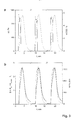
- Figure 3 shows the sampling conditions ( fig.3a ) and detection signal 51 ( fig.3b ) for three breath pulses.
- the pressure sensor 21 is arranged in the sampling part 4 close to the orifice 44.
- the pressure drop ( ⁇ p) over the orifice 44 is plotted over time (t) for three exhalation pulses for three breath sample 7 collections.
- a digital readout meaning the sampling signal 41, gives direct feedback of the achieved value while exhaling on breath sample 7 collection. It can be seen from the graph that exhaling for 30 s is possible and the pressure sensor 21 shows fast ( ⁇ 2 s) recovery times.
- the duration of the breath sample 7 collection is represented as striped area for the first breath pulse.
- the desired pressure drop values can be maintained by the user within ⁇ 100 Pa. Typically, the pressure drop of the first breath pulse is slightly too high at about 1100 Pa.
- the required target value of the pressure drop of 980 Pa corresponds to a controlled exhalation flow of 50 mL/s which is indicated by the horizontal dashed line in fig.4a .
- Figure 3a shows CO2 concentration (c(CO2)) peaks for the same breath pulses as a function of time, depicted as dashed line.
- CO2 concentration c(CO2)
- the three pulses show good reproducibility with respect to the peak value as well as the length. Concentration peaks are located between 5 to 6 %. The similar values are reported in literature.
- the CO2 sensor enables determination of the end-tidal fraction of the breath (CO2 > 3 % - represented as horizontal dashed line), where acetone appears in highest concentrations. By looking at the graph, it can be seen that for an exhalation time of 30 s, breath of the end-tidal fraction can be sampled for more than 60 s.
- the sampling time and exposure time of the Si:WO3 sensor with the breath sample 7 can be significantly prolonged. A delay time of 3 seconds with respect to the pressure sensor is measured. This can be explained by the fact that the breath sample 7 first needs to travel the connection element of a length of 600 mm to reach the CO2 sensor.
- acetone sensor 52 response S; left axis
- acetone concentration c(ac); right axis
- the solid line represents the acetone sensor 52 response while the dashed line stands for the acetone calibrated concentration determined by mass spectrometer measurements of the same breath sample 7.
- Sensor 52 responses show good reproducibility, although the sensor 52 does not seem to perfectly stabilize and reach steady-state.
- the acetone sensor 52 integrated into the sampling part 4 of the fat burning analyser 1 showed larger response times of 27 s compared to a value of 12 s in literature.
- the fat burning analyser 1 is applied to monitor breath acetone of 20 volunteers/user. Each user was tested twice: one time with initial exercise to stimulate fat burn, and thus increase acetone excretion, and another time remaining at rest throughout the experiment (control).
- the sensor detects an onset of increasing acetone levels after 60 min (in average) and indicates a steady increase until the end of the experiment.
- the fat burning analyser 1 has been disclosed and characterized. It has been shown that reproducible and controllable sampling/sample collection with respect to CO2 concentration and/or flow is enabled. Especially, triggered and prolonged sampling of the end-tidal fraction of human breath can be achieved by utilising the sampling signal 41 of the sampling part.
- the portable sampling part 4 in combination with an analysis unit 5, in particular a acetone sensor 52, in particular a Si-doped WO3 flame-made sensor, can be successfully applied to display breath acetone dynamics not only during physical activity on a bicycle ergometer, but also in post exercise and normal control measurements providing information of the fat burning intensity as descriped above. An average 2.5-fold breath acetone increase after 90 min exercising followed by 3 h post exercise fasting has been found.
Landscapes
- Health & Medical Sciences (AREA)
- Life Sciences & Earth Sciences (AREA)
- Engineering & Computer Science (AREA)
- Molecular Biology (AREA)
- Biomedical Technology (AREA)
- Physics & Mathematics (AREA)
- General Health & Medical Sciences (AREA)
- Biophysics (AREA)
- Pathology (AREA)
- Surgery (AREA)
- Pulmonology (AREA)
- Heart & Thoracic Surgery (AREA)
- Medical Informatics (AREA)
- Physiology (AREA)
- Animal Behavior & Ethology (AREA)
- Public Health (AREA)
- Veterinary Medicine (AREA)
- Obesity (AREA)
- Emergency Medicine (AREA)
- Chemical & Material Sciences (AREA)
- Urology & Nephrology (AREA)
- Hematology (AREA)
- Food Science & Technology (AREA)
- Medicinal Chemistry (AREA)
- Analytical Chemistry (AREA)
- Biochemistry (AREA)
- General Physics & Mathematics (AREA)
- Immunology (AREA)
- Investigating Or Analysing Biological Materials (AREA)
- Sampling And Sample Adjustment (AREA)
Claims (15)
- Analyseur de combustion de graisses portable (1) pour surveiller l'intensité de combustion des graisses d'un utilisateur à partir de l'haleine de l'utilisateur, l'analyseur (1) comprenant :une partie d'échantillonnage (4), une unité d'analyse (5) et une unité de traitement (6) ;la partie d'échantillonnage (4) étant équipée pour recueillir un échantillon d'haleine (7) de l'utilisateur,la partie d'échantillonnage (4) étant équipée pour collecter des informations sur les conditions de collecte de l'échantillon d'haleine (7),la partie d'échantillonnage (4) étant équipée pour fournir un signal d'échantillonnage (41) corrélé à la condition de collecte ;le signal d'échantillonnage étant capable d'indiquer le début de la partie de fin d'expiration de l'échantillon d'haleine ;l'unité d'analyse (5) étant équipée pour fournir un signal de détection (51) correspondant à une présence d'acétone dans l'échantillon d'haleine collecté (7) de la partie de fin d'expiration de l'échantillon d'haleine ;l'unité de traitement (6) étant équipéepour recevoir le signal d'échantillonnage (41) et/ou le signal de détection (51) etpour évaluer le signal d'échantillonnage (41) et/ou le signal de détection (51) etpour fournir un signal de sortie (61) corrélé à l'intensité de combustion des graisses de l'utilisateur ;caractérisé en ce que
la partie d'échantillonnage et l'unité d'analyse sont séparées dans l'espace ; etl'unité d'analyse étant configurée pour recevoir la partie d'haleine de fin d'expiration en raison d'un guidage déclenché lors de l'indication du début de la partie de fin d'expiration de l'échantillon d'haleine par le signal d'échantillonnage. - Analyseur de combustion de graisses (1) selon la revendication 1, l'intensité de combustion des graisses de l'utilisateur étant fournie de manière reproductible sur la base des informations de la condition de collecte fournie par le signal d'échantillonnage.
- Analyseur de combustion de graisses (1) selon l'une des revendications 1 et 2, le signal d'échantillonnage étant capable de déclencher le signal de détection.
- Analyseur de combustion de graisses (1) selon l'une des revendications 1 à 3, le signal d'échantillonnage étant capable d'indiquer un échantillon d'haleine, en particulier le début de la partie de fin d'expiration de l'échantillon d'haleine,
en particulier le signal d'échantillonnage comprenant des informations sur au moins l'une des grandeurs suivantes : pression, temps/durée de l'échantillon d'haleine, volume de l'échantillon d'haleine, débit de l'échantillon d'haleine, température, concentration en CO2 et/ou humidité de l'échantillon d'haleine. - Analyseur de combustion de graisses (1) selon l'une des revendications 1 à 4, l'unité de traitement étant équipée pour reconnaître l'échantillon d'haleine en raison du signal d'échantillonnage et de sa comparaison avec des valeurs cibles correspondantes.
- Analyseur de combustion de graisses (1) selon l'une des revendications 1 à 5, la partie d'échantillonnage (4) étant équipée pour permettre à l'utilisateur d'atteindre et/ou de maintenir une valeur cible et/ou une durée cible pour la collecte d'un échantillon d'haleine (7) de l'utilisateur,
en particulier, l'utilisateur pouvant atteindre et/ou maintenir une valeur cible et/ou une durée cible pour le prélèvement d'un échantillon d'haleine en affichant les informations relatives à la condition du prélèvement de l'échantillon d'haleine (7) et/ou la valeur cible et/ou la durée du prélèvement de l'échantillon d'haleine (7). - Analyseur de combustion de graisses (1) selon l'une des revendications 1 à 6, la partie d'échantillonnage (4) comprenant une chambre d'échantillonnage (43) pour recueillir l'échantillon d'haleine (7), en particulier la chambre d'échantillonnage (43) étant conçue comme un tube d'échantillonnage, en particulier la chambre d'échantillonnage (43) comprenant du Téflon®,en particulier, la chambre d'échantillonnage étant équipée pour tamponner l'échantillon d'haleine (7), en particulier la chambre d'échantillonnage (43) étant conçue comme un tube d'échantillonnage,en particulier, la partie d'échantillonnage (4) comprenant une entrée (45) et/ou une sortie (53),l'utilisateur respirant à travers l'entrée (45) dans la partie d'échantillonnage (4) et l'haleine s'écoulant à travers la partie d'échantillonnage (4) étant guidé vers la sortie (53) et permettant à l'air d'être poussé hors de la partie d'échantillonnage (4) et permettant à la partie de fin d'expiration mixte de l'échantillon d'haleine (7) de rester dans la partie d'échantillonnage (4).
- Analyseur de combustion de graisses (1) selon l'une des revendications 1 à 7, la partie d'échantillonnage (4) comprenant un capteur (2) équipé pour fournir des informations sur l'état de la collecte de l'échantillon d'haleine (7),en particulier, le capteur (2) étant conçu comme au moins l'un de :- un capteur de pression (21) étant agencé dans la partie d'échantillonnage (4) et capable de fournir des informations sur l'intensité de l'expiration et/ou le volume de l'expiration de l'utilisateur,en particulier le capteur de pression (21) étant agencé à proximité d'un orifice (44), l'orifice (44) étant agencé à une entrée (45) de la chambre d'échantillonnage (43),en particulier, le capteur de pression (21) étant équipé pour fournir un signal de déclenchement basé sur la collecte de l'échantillon d'haleine de fin d'expiration (7) ;- un capteur d'humidité (22) étant agencé dans la partie d'échantillonnage (4) et capable de fournir des informations sur la condition d'échantillonnage de l'échantillon d'haleine (7), en particulier le capteur d'humidité (22) fournissant un signal d'échantillonnage (41) sur la collecte de l'échantillon d'haleine (7),en particulier, le capteur d'humidité (22) étant équipé pour fournir un signal de déclenchement lors du prélèvement de l'échantillon d'haleine (7) si l'humidité relative de l'échantillon d'haleine (7) est supérieure à 70 % ;en particulier, le signal de déclenchement étant fourni par un signal d'échantillonnage combiné (41) du capteur d'humidité (22) et du capteur de pression (21) ; et- un capteur de CO2 (23) étant agencé dans la partie d'échantillonnage (4) et capable de fournir des informations sur la partie de l'échantillon d'haleine (7) à analyser ; en particulier, le capteur de CO2 (23) étant capable d'indiquer la partie de l'échantillon d'haleine (7) à détecter ;- un capteur de débit étant agencé dans la partie d'échantillonnage (4) et capable de fournir des informations sur le débit de l'échantillon d'haleine,- un capteur de température étant agencé dans la partie d'échantillonnage (4) et capable de fournir des informations sur la température de l'échantillon d'haleine ;en particulier le capteur (2) étant agencé entre une entrée (45) et une sortie (53), en particulier à proximité de l'entrée (45) et/ou de la sortie (53) ;en particulier le capteur (2), en particulier le capteur de CO2 (23), étant capable de déclencher la durée et/ou le point de départ de la détection de l'échantillon d'haleine (7), en particulier le capteur de CO2 (23) étant équipé pour fournir un signal de déclenchement sur la collecte de l'échantillon d'haleine (7) si la concentration de CO2 de l'échantillon d'haleine (7) est supérieure à 3 %.
- Analyseur de combustion de graisses (1) selon l'une des revendications 1 à 8, l'unité d'analyse (5) comprenant un capteur d'acétone (52), le capteur d'acétone (52) étant capable de détecter la présence d'acétone dans l'échantillon d'haleine (7), en particulier le capteur d'acétone (52) étant capable de détecter la concentration d'acétone,
le capteur d'acétone (52) étant capable de fournir le signal de détection (51) lors de l'exposition à l'acétone présente dans l'échantillon d'haleine (7). - Analyseur de combustion de graisses (1) selon l'une des revendications 1 à 9, l'unité de traitement (6) étant équipée pour recevoir le signal d'échantillonnage (41) et/ou le signal de détection (51), lesdits signaux comprenant des informations sur le débit, l'humidité relative, la pression, le temps/la durée, la température, la concentration en CO2 et/ou la concentration en acétone de l'échantillon d'haleine (7).
- Analyseur de combustion de graisses (1) selon l'une des revendications 1 à 10, l'unité de traitement (6) comprenant une unité de mémoire, l'unité de traitement (6) étant capable de comparer le signal de détection (51) à un signal de référence stocké dans la mémoire, en particulier l'unité de traitement (6) étant équipée pour calculer le signal de sortie (61) à partir du signal de détection (51) et du signal de référence, en particulier le signal d'échantillonnage (41) étant pris en compte en comparant le signal de détection (51) au signal de référence et/ou au signal d'échantillonnage (41).
- Analyseur de combustion de graisses (1) selon l'une des revendications 1 à 11, l'analyseur de combustion de graisses (1) étant équipé pour permettre à l'utilisateur de commander les conditions d'expiration de l'échantillon d'haleine (7) en surveillant le signal d'échantillonnage (41) et en fournissant une boucle de rétroaction permettant à l'utilisateur d'atteindre et/ou de maintenir une valeur cible pour l'échantillonnage.
- Analyseur de combustion de graisses (1) selon l'une des revendications 1 à 12, au moins une partie de la partie d'échantillonnage (4) et de l'unité d'analyse (5) étant chauffée, en particulier l'analyseur de combustion de graisses (1) étant au moins partiellement chauffé au-dessus de la température ambiante, en particulier l'analyseur de combustion de graisses (1) étant au moins partiellement chauffé à au moins 50 °C.
- Utilisation d'un analyseur de combustion de graisses (1) selon l'une des revendications 1 à 13pour surveiller le taux de combustion des graisses de l'utilisateur pendant l'exercice ou pendant le repos,pour surveiller le métabolisme de combustion des graisses de l'utilisateur,pour adapter un régime alimentaire sur la base d'un taux de combustion des graisses surveillé de l'utilisateur,pour aider l'utilisateur à suivre un régime alimentaire basé sur le taux de combustion des graisses de l'utilisateur, et/oupour fournir des informations de diagnostic liées à l'échantillon d'haleine (7) collecté dans l'analyseur de combustion de graisses (1), en particulier pour le diagnostic du diabète.
- Procédé de surveillance de la combustion des graisses avec un analyseur d'haleine portable (1) selon l'une quelconque des revendications précédentes 1 à 13, le procédé comprenant les étapes suivantes :- fournir un analyseur d'haleine (1) selon l'une quelconque des revendications 1 à 13 ;- laisser l'utilisateur expirer dans l'analyseur de combustion de graisses (1), en particulier dans la partie d'échantillonnage (4) ;- recueillir un échantillon d'haleine (7) ;- fournir le signal d'échantillonnage (41) à partir de la partie d'échantillonnage (4) ;- guider l'échantillon d'haleine (7) de la partie d'échantillonnage (4) vers l'unité d'analyse (5) ;- détecter la présence d'acétone dans l'échantillon d'haleine (7) avec un capteur d'acétone (52) dans l'unité d'analyse (5),- fournir un signal de détection (51) à partir de l'unité d'analyse (5),- calculer l'intensité de combustion des graisses à partir du signal d'échantillonnage (41) et/ou du signal de détection (51) ;- générer un signal de sortie (61) correspondant à l'intensité de combustion des graisses ;afficher le signal de sortie (61) comme une mesure de l'intensité de combustion des graisses.
Applications Claiming Priority (1)
| Application Number | Priority Date | Filing Date | Title |
|---|---|---|---|
| CH15672016 | 2016-11-29 |
Publications (2)
| Publication Number | Publication Date |
|---|---|
| EP3326523A1 EP3326523A1 (fr) | 2018-05-30 |
| EP3326523B1 true EP3326523B1 (fr) | 2021-10-06 |
Family
ID=57583006
Family Applications (1)
| Application Number | Title | Priority Date | Filing Date |
|---|---|---|---|
| EP17204314.3A Active EP3326523B1 (fr) | 2016-11-29 | 2017-11-29 | Analyseur de la combustion des graisses |
Country Status (3)
| Country | Link |
|---|---|
| US (1) | US10667722B2 (fr) |
| EP (1) | EP3326523B1 (fr) |
| ES (1) | ES2901887T3 (fr) |
Families Citing this family (4)
| Publication number | Priority date | Publication date | Assignee | Title |
|---|---|---|---|---|
| US11375920B2 (en) | 2018-07-10 | 2022-07-05 | Readout, Inc. | Multi-sensor breath analyte detection device |
| JP2021531930A (ja) * | 2018-07-10 | 2021-11-25 | リードアウト インコーポレイテッド | 呼気アナライト検出装置 |
| WO2021119395A1 (fr) * | 2019-12-12 | 2021-06-17 | Avisa Pharma, Inc. | Systèmes et procédés de détection d'infections |
| US11068803B1 (en) * | 2020-10-09 | 2021-07-20 | Metre, Inc. | Systems and methods for predicting analyte concentrations via machine learning techniques |
Citations (1)
| Publication number | Priority date | Publication date | Assignee | Title |
|---|---|---|---|---|
| WO2013003429A1 (fr) * | 2011-06-28 | 2013-01-03 | Ikaria, Inc. | Appareil de surveillance des gaz en fin d'expiration |
Family Cites Families (8)
| Publication number | Priority date | Publication date | Assignee | Title |
|---|---|---|---|---|
| JP2762882B2 (ja) | 1992-12-28 | 1998-06-04 | 鹿島建設株式会社 | 地下止水壁の構築法 |
| AU2001275290A1 (en) | 2000-06-07 | 2001-12-17 | Healthetech, Inc. | Breath ketone analyzer |
| JP2001349888A (ja) * | 2000-06-08 | 2001-12-21 | Matsushita Electric Ind Co Ltd | 体脂肪燃焼量測定装置および有酸素運動器具 |
| US10401318B2 (en) * | 2011-03-14 | 2019-09-03 | Anastasia Rigas | Breath analyzer and breath test methods |
| EP3871599A1 (fr) * | 2011-12-22 | 2021-09-01 | Circassia Ab | Dispositif d'échantillonnage |
| EP2762882B1 (fr) * | 2013-01-31 | 2020-11-25 | Sensirion AG | Dispositif électronique portable avec capteur de cétone |
| US20170074857A1 (en) * | 2014-03-04 | 2017-03-16 | University Of Florida Research Foundation, Inc. | Medication adherence monitoring device |
| US9897590B2 (en) * | 2015-05-20 | 2018-02-20 | Gm Nameplate, Inc. | Breath capture and sampling system |
-
2017
- 2017-11-29 ES ES17204314T patent/ES2901887T3/es active Active
- 2017-11-29 EP EP17204314.3A patent/EP3326523B1/fr active Active
- 2017-11-29 US US15/825,671 patent/US10667722B2/en active Active
Patent Citations (1)
| Publication number | Priority date | Publication date | Assignee | Title |
|---|---|---|---|---|
| WO2013003429A1 (fr) * | 2011-06-28 | 2013-01-03 | Ikaria, Inc. | Appareil de surveillance des gaz en fin d'expiration |
Also Published As
| Publication number | Publication date |
|---|---|
| US20180146888A1 (en) | 2018-05-31 |
| US10667722B2 (en) | 2020-06-02 |
| ES2901887T3 (es) | 2022-03-24 |
| EP3326523A1 (fr) | 2018-05-30 |
Similar Documents
| Publication | Publication Date | Title |
|---|---|---|
| EP3326523B1 (fr) | Analyseur de la combustion des graisses | |
| US20190120821A1 (en) | Breath analysis device | |
| EP3448254B1 (fr) | Procédé de collecte d'une partie sélective de l'haleine d'un sujet | |
| US3830630A (en) | Apparatus and method for alcoholic breath and other gas analysis | |
| CN102469954B (zh) | 确定呼出一氧化氮的方法和设备 | |
| KR20160047565A (ko) | 범용 호흡 분석 샘플링 장치 | |
| US20150013429A1 (en) | Method and Device for Express Analysis of Acetone Traces in Gases | |
| JP2005519272A (ja) | 呼気収集システム | |
| CN110226931B (zh) | 一种呼气分析装置及使用方法 | |
| CN110290747B (zh) | 用于呼吸分析的方法和装置 | |
| Jones | Quantitative measurements of the alcohol concentration and the temperature of breath during a prolonged exhalation | |
| Dummer et al. | Accurate, reproducible measurement of acetone concentration in breath using selected ion flow tube-mass spectrometry | |
| JP2014507632A (ja) | 呼吸アルコール濃度を測定するための方法及び装置 | |
| WO2019074922A1 (fr) | Dispositif d'analyse de la respiration | |
| KR20150013358A (ko) | 호흡 알코올 농도 측정 장치 및 측정 방법 | |
| EP2984484B1 (fr) | Appareil et procédé d'analyse de gaz respiratoires pour la détection de l'halitose | |
| WO2017189546A1 (fr) | Dispositif d'analyse respiratoire | |
| CN205228892U (zh) | 一种呼气末采样装置 | |
| EP3187104A1 (fr) | Dispositif de d'analyse et de prélèvement de l'haleine | |
| de Lacy Costello et al. | A sensor system for monitoring the simple gases hydrogen, carbon monoxide, hydrogen sulfide, ammonia and ethanol in exhaled breath | |
| WO2014132077A1 (fr) | Appareil et procédé d'analyse de composé organique volatil d'air expiré et procédé d'étalonnage | |
| US20230263425A1 (en) | Temporal sampling in a wearable breath analyser | |
| KR20200077639A (ko) | 가스 농도 측정장치 및 이를 이용한 가스 농도 측정방법 | |
| JP2016218065A (ja) | ガスセンサモジュール | |
| JP2014018622A (ja) | 呼気ガス分析装置の遅れ時間の校正 |
Legal Events
| Date | Code | Title | Description |
|---|---|---|---|
| PUAI | Public reference made under article 153(3) epc to a published international application that has entered the european phase |
Free format text: ORIGINAL CODE: 0009012 |
|
| STAA | Information on the status of an ep patent application or granted ep patent |
Free format text: STATUS: THE APPLICATION HAS BEEN PUBLISHED |
|
| AK | Designated contracting states |
Kind code of ref document: A1 Designated state(s): AL AT BE BG CH CY CZ DE DK EE ES FI FR GB GR HR HU IE IS IT LI LT LU LV MC MK MT NL NO PL PT RO RS SE SI SK SM TR |
|
| AX | Request for extension of the european patent |
Extension state: BA ME |
|
| STAA | Information on the status of an ep patent application or granted ep patent |
Free format text: STATUS: REQUEST FOR EXAMINATION WAS MADE |
|
| 17P | Request for examination filed |
Effective date: 20181129 |
|
| RBV | Designated contracting states (corrected) |
Designated state(s): AL AT BE BG CH CY CZ DE DK EE ES FI FR GB GR HR HU IE IS IT LI LT LU LV MC MK MT NL NO PL PT RO RS SE SI SK SM TR |
|
| STAA | Information on the status of an ep patent application or granted ep patent |
Free format text: STATUS: EXAMINATION IS IN PROGRESS |
|
| 17Q | First examination report despatched |
Effective date: 20190730 |
|
| STAA | Information on the status of an ep patent application or granted ep patent |
Free format text: STATUS: EXAMINATION IS IN PROGRESS |
|
| GRAP | Despatch of communication of intention to grant a patent |
Free format text: ORIGINAL CODE: EPIDOSNIGR1 |
|
| STAA | Information on the status of an ep patent application or granted ep patent |
Free format text: STATUS: GRANT OF PATENT IS INTENDED |
|
| INTG | Intention to grant announced |
Effective date: 20210510 |
|
| GRAS | Grant fee paid |
Free format text: ORIGINAL CODE: EPIDOSNIGR3 |
|
| GRAA | (expected) grant |
Free format text: ORIGINAL CODE: 0009210 |
|
| STAA | Information on the status of an ep patent application or granted ep patent |
Free format text: STATUS: THE PATENT HAS BEEN GRANTED |
|
| AK | Designated contracting states |
Kind code of ref document: B1 Designated state(s): AL AT BE BG CH CY CZ DE DK EE ES FI FR GB GR HR HU IE IS IT LI LT LU LV MC MK MT NL NO PL PT RO RS SE SI SK SM TR |
|
| REG | Reference to a national code |
Ref country code: GB Ref legal event code: FG4D |
|
| REG | Reference to a national code |
Ref country code: CH Ref legal event code: EP Ref country code: AT Ref legal event code: REF Ref document number: 1435524 Country of ref document: AT Kind code of ref document: T Effective date: 20211015 |
|
| REG | Reference to a national code |
Ref country code: IE Ref legal event code: FG4D |
|
| REG | Reference to a national code |
Ref country code: DE Ref legal event code: R096 Ref document number: 602017047081 Country of ref document: DE |
|
| REG | Reference to a national code |
Ref country code: SE Ref legal event code: TRGR |
|
| REG | Reference to a national code |
Ref country code: LT Ref legal event code: MG9D |
|
| REG | Reference to a national code |
Ref country code: NL Ref legal event code: MP Effective date: 20211006 |
|
| REG | Reference to a national code |
Ref country code: AT Ref legal event code: MK05 Ref document number: 1435524 Country of ref document: AT Kind code of ref document: T Effective date: 20211006 |
|
| REG | Reference to a national code |
Ref country code: ES Ref legal event code: FG2A Ref document number: 2901887 Country of ref document: ES Kind code of ref document: T3 Effective date: 20220324 |
|
| PG25 | Lapsed in a contracting state [announced via postgrant information from national office to epo] |
Ref country code: RS Free format text: LAPSE BECAUSE OF FAILURE TO SUBMIT A TRANSLATION OF THE DESCRIPTION OR TO PAY THE FEE WITHIN THE PRESCRIBED TIME-LIMIT Effective date: 20211006 Ref country code: LT Free format text: LAPSE BECAUSE OF FAILURE TO SUBMIT A TRANSLATION OF THE DESCRIPTION OR TO PAY THE FEE WITHIN THE PRESCRIBED TIME-LIMIT Effective date: 20211006 Ref country code: FI Free format text: LAPSE BECAUSE OF FAILURE TO SUBMIT A TRANSLATION OF THE DESCRIPTION OR TO PAY THE FEE WITHIN THE PRESCRIBED TIME-LIMIT Effective date: 20211006 Ref country code: BG Free format text: LAPSE BECAUSE OF FAILURE TO SUBMIT A TRANSLATION OF THE DESCRIPTION OR TO PAY THE FEE WITHIN THE PRESCRIBED TIME-LIMIT Effective date: 20220106 Ref country code: AT Free format text: LAPSE BECAUSE OF FAILURE TO SUBMIT A TRANSLATION OF THE DESCRIPTION OR TO PAY THE FEE WITHIN THE PRESCRIBED TIME-LIMIT Effective date: 20211006 |
|
| PG25 | Lapsed in a contracting state [announced via postgrant information from national office to epo] |
Ref country code: IS Free format text: LAPSE BECAUSE OF FAILURE TO SUBMIT A TRANSLATION OF THE DESCRIPTION OR TO PAY THE FEE WITHIN THE PRESCRIBED TIME-LIMIT Effective date: 20220206 Ref country code: PT Free format text: LAPSE BECAUSE OF FAILURE TO SUBMIT A TRANSLATION OF THE DESCRIPTION OR TO PAY THE FEE WITHIN THE PRESCRIBED TIME-LIMIT Effective date: 20220207 Ref country code: PL Free format text: LAPSE BECAUSE OF FAILURE TO SUBMIT A TRANSLATION OF THE DESCRIPTION OR TO PAY THE FEE WITHIN THE PRESCRIBED TIME-LIMIT Effective date: 20211006 Ref country code: NO Free format text: LAPSE BECAUSE OF FAILURE TO SUBMIT A TRANSLATION OF THE DESCRIPTION OR TO PAY THE FEE WITHIN THE PRESCRIBED TIME-LIMIT Effective date: 20220106 Ref country code: NL Free format text: LAPSE BECAUSE OF FAILURE TO SUBMIT A TRANSLATION OF THE DESCRIPTION OR TO PAY THE FEE WITHIN THE PRESCRIBED TIME-LIMIT Effective date: 20211006 Ref country code: LV Free format text: LAPSE BECAUSE OF FAILURE TO SUBMIT A TRANSLATION OF THE DESCRIPTION OR TO PAY THE FEE WITHIN THE PRESCRIBED TIME-LIMIT Effective date: 20211006 Ref country code: HR Free format text: LAPSE BECAUSE OF FAILURE TO SUBMIT A TRANSLATION OF THE DESCRIPTION OR TO PAY THE FEE WITHIN THE PRESCRIBED TIME-LIMIT Effective date: 20211006 Ref country code: GR Free format text: LAPSE BECAUSE OF FAILURE TO SUBMIT A TRANSLATION OF THE DESCRIPTION OR TO PAY THE FEE WITHIN THE PRESCRIBED TIME-LIMIT Effective date: 20220107 |
|
| REG | Reference to a national code |
Ref country code: DE Ref legal event code: R097 Ref document number: 602017047081 Country of ref document: DE |
|
| PG25 | Lapsed in a contracting state [announced via postgrant information from national office to epo] |
Ref country code: SM Free format text: LAPSE BECAUSE OF FAILURE TO SUBMIT A TRANSLATION OF THE DESCRIPTION OR TO PAY THE FEE WITHIN THE PRESCRIBED TIME-LIMIT Effective date: 20211006 Ref country code: SK Free format text: LAPSE BECAUSE OF FAILURE TO SUBMIT A TRANSLATION OF THE DESCRIPTION OR TO PAY THE FEE WITHIN THE PRESCRIBED TIME-LIMIT Effective date: 20211006 Ref country code: RO Free format text: LAPSE BECAUSE OF FAILURE TO SUBMIT A TRANSLATION OF THE DESCRIPTION OR TO PAY THE FEE WITHIN THE PRESCRIBED TIME-LIMIT Effective date: 20211006 Ref country code: MC Free format text: LAPSE BECAUSE OF FAILURE TO SUBMIT A TRANSLATION OF THE DESCRIPTION OR TO PAY THE FEE WITHIN THE PRESCRIBED TIME-LIMIT Effective date: 20211006 Ref country code: LU Free format text: LAPSE BECAUSE OF NON-PAYMENT OF DUE FEES Effective date: 20211129 Ref country code: EE Free format text: LAPSE BECAUSE OF FAILURE TO SUBMIT A TRANSLATION OF THE DESCRIPTION OR TO PAY THE FEE WITHIN THE PRESCRIBED TIME-LIMIT Effective date: 20211006 Ref country code: DK Free format text: LAPSE BECAUSE OF FAILURE TO SUBMIT A TRANSLATION OF THE DESCRIPTION OR TO PAY THE FEE WITHIN THE PRESCRIBED TIME-LIMIT Effective date: 20211006 Ref country code: CZ Free format text: LAPSE BECAUSE OF FAILURE TO SUBMIT A TRANSLATION OF THE DESCRIPTION OR TO PAY THE FEE WITHIN THE PRESCRIBED TIME-LIMIT Effective date: 20211006 Ref country code: BE Free format text: LAPSE BECAUSE OF NON-PAYMENT OF DUE FEES Effective date: 20211130 |
|
| REG | Reference to a national code |
Ref country code: BE Ref legal event code: MM Effective date: 20211130 |
|
| PLBE | No opposition filed within time limit |
Free format text: ORIGINAL CODE: 0009261 |
|
| STAA | Information on the status of an ep patent application or granted ep patent |
Free format text: STATUS: NO OPPOSITION FILED WITHIN TIME LIMIT |
|
| 26N | No opposition filed |
Effective date: 20220707 |
|
| PG25 | Lapsed in a contracting state [announced via postgrant information from national office to epo] |
Ref country code: IE Free format text: LAPSE BECAUSE OF NON-PAYMENT OF DUE FEES Effective date: 20211129 Ref country code: AL Free format text: LAPSE BECAUSE OF FAILURE TO SUBMIT A TRANSLATION OF THE DESCRIPTION OR TO PAY THE FEE WITHIN THE PRESCRIBED TIME-LIMIT Effective date: 20211006 |
|
| PG25 | Lapsed in a contracting state [announced via postgrant information from national office to epo] |
Ref country code: SI Free format text: LAPSE BECAUSE OF FAILURE TO SUBMIT A TRANSLATION OF THE DESCRIPTION OR TO PAY THE FEE WITHIN THE PRESCRIBED TIME-LIMIT Effective date: 20211006 |
|
| PG25 | Lapsed in a contracting state [announced via postgrant information from national office to epo] |
Ref country code: HU Free format text: LAPSE BECAUSE OF FAILURE TO SUBMIT A TRANSLATION OF THE DESCRIPTION OR TO PAY THE FEE WITHIN THE PRESCRIBED TIME-LIMIT; INVALID AB INITIO Effective date: 20171129 |
|
| PG25 | Lapsed in a contracting state [announced via postgrant information from national office to epo] |
Ref country code: CY Free format text: LAPSE BECAUSE OF FAILURE TO SUBMIT A TRANSLATION OF THE DESCRIPTION OR TO PAY THE FEE WITHIN THE PRESCRIBED TIME-LIMIT Effective date: 20211006 |
|
| PGFP | Annual fee paid to national office [announced via postgrant information from national office to epo] |
Ref country code: GB Payment date: 20231123 Year of fee payment: 7 |
|
| PGFP | Annual fee paid to national office [announced via postgrant information from national office to epo] |
Ref country code: SE Payment date: 20231120 Year of fee payment: 7 Ref country code: IT Payment date: 20231124 Year of fee payment: 7 Ref country code: FR Payment date: 20231120 Year of fee payment: 7 Ref country code: DE Payment date: 20231121 Year of fee payment: 7 Ref country code: CH Payment date: 20231202 Year of fee payment: 7 |
|
| PGFP | Annual fee paid to national office [announced via postgrant information from national office to epo] |
Ref country code: ES Payment date: 20240129 Year of fee payment: 7 |
|
| PG25 | Lapsed in a contracting state [announced via postgrant information from national office to epo] |
Ref country code: MK Free format text: LAPSE BECAUSE OF FAILURE TO SUBMIT A TRANSLATION OF THE DESCRIPTION OR TO PAY THE FEE WITHIN THE PRESCRIBED TIME-LIMIT Effective date: 20211006 |
|
| PG25 | Lapsed in a contracting state [announced via postgrant information from national office to epo] |
Ref country code: TR Free format text: LAPSE BECAUSE OF FAILURE TO SUBMIT A TRANSLATION OF THE DESCRIPTION OR TO PAY THE FEE WITHIN THE PRESCRIBED TIME-LIMIT Effective date: 20211006 |