EP3326506A1 - Dust container for a vacuum cleaner - Google Patents
Dust container for a vacuum cleaner Download PDFInfo
- Publication number
- EP3326506A1 EP3326506A1 EP16200150.7A EP16200150A EP3326506A1 EP 3326506 A1 EP3326506 A1 EP 3326506A1 EP 16200150 A EP16200150 A EP 16200150A EP 3326506 A1 EP3326506 A1 EP 3326506A1
- Authority
- EP
- European Patent Office
- Prior art keywords
- dust container
- vacuum cleaner
- opening
- connector plate
- holder
- Prior art date
- Legal status (The legal status is an assumption and is not a legal conclusion. Google has not performed a legal analysis and makes no representation as to the accuracy of the status listed.)
- Granted
Links
Images

Classifications
-
- A—HUMAN NECESSITIES
- A47—FURNITURE; DOMESTIC ARTICLES OR APPLIANCES; COFFEE MILLS; SPICE MILLS; SUCTION CLEANERS IN GENERAL
- A47L—DOMESTIC WASHING OR CLEANING; SUCTION CLEANERS IN GENERAL
- A47L9/00—Details or accessories of suction cleaners, e.g. mechanical means for controlling the suction or for effecting pulsating action; Storing devices specially adapted to suction cleaners or parts thereof; Carrying-vehicles specially adapted for suction cleaners
- A47L9/10—Filters; Dust separators; Dust removal; Automatic exchange of filters
- A47L9/14—Bags or the like; Rigid filtering receptacles; Attachment of, or closures for, bags or receptacles
- A47L9/1418—Impermeable dust collecting bags
-
- A—HUMAN NECESSITIES
- A47—FURNITURE; DOMESTIC ARTICLES OR APPLIANCES; COFFEE MILLS; SPICE MILLS; SUCTION CLEANERS IN GENERAL
- A47L—DOMESTIC WASHING OR CLEANING; SUCTION CLEANERS IN GENERAL
- A47L9/00—Details or accessories of suction cleaners, e.g. mechanical means for controlling the suction or for effecting pulsating action; Storing devices specially adapted to suction cleaners or parts thereof; Carrying-vehicles specially adapted for suction cleaners
- A47L9/10—Filters; Dust separators; Dust removal; Automatic exchange of filters
- A47L9/14—Bags or the like; Rigid filtering receptacles; Attachment of, or closures for, bags or receptacles
- A47L9/1427—Means for mounting or attaching bags or filtering receptacles in suction cleaners; Adapters
-
- A—HUMAN NECESSITIES
- A47—FURNITURE; DOMESTIC ARTICLES OR APPLIANCES; COFFEE MILLS; SPICE MILLS; SUCTION CLEANERS IN GENERAL
- A47L—DOMESTIC WASHING OR CLEANING; SUCTION CLEANERS IN GENERAL
- A47L9/00—Details or accessories of suction cleaners, e.g. mechanical means for controlling the suction or for effecting pulsating action; Storing devices specially adapted to suction cleaners or parts thereof; Carrying-vehicles specially adapted for suction cleaners
- A47L9/10—Filters; Dust separators; Dust removal; Automatic exchange of filters
- A47L9/14—Bags or the like; Rigid filtering receptacles; Attachment of, or closures for, bags or receptacles
- A47L9/1427—Means for mounting or attaching bags or filtering receptacles in suction cleaners; Adapters
- A47L9/1436—Connecting plates, e.g. collars, end closures
Definitions
- the present disclosure relates to a dust container for a vacuum cleaner, the dust container comprising a dust bag, made of an air permeable material, and a connector plate, surrounding an inlet in the dust bag, such that the connector plate can correctly position the inlet within a vacuum cleaner by the connector plate being inserted in a holder of the vacuum cleaner.
- the connector plate Thanks to the connector plate, the inlet of the dust bag can be reliably positioned and oriented to receive a flow of dust laden air from the vacuum cleaner inlet. Further, the connector plate may have means for securing the dust bag during use and also securing parts of the connector plate, such as a shutter arrangement, to the vacuum cleaner during removal of the dust bag to have an automatic closure of the dust bag during removal.
- the connector plate can trigger a feedback switch in the holder of the vacuum cleaner to verify that a dust container has been correctly installed in the holder, thus enabling the vacuum cleaner to prevent use in case of an absent or incorrectly installed dust container. Such use could otherwise damage the vacuum cleaner by injecting heavily dust laden air into a fan/motor arrangement.
- One problem associated with dust containers of this type is how to improve the securing of the dust bag to the vacuum cleaner during use and removal of the dust bag, and/or to have a more versatile way of sensing an absent or incorrectly installed dust container.
- An object of the present invention is to solve, or at least mitigate, this problem in the art. This object is achieved by means of a dust container as defined in claim 1 and preceding claims.
- a vacuum cleaner comprising the dust container is further envisaged.
- a dust container for a vacuum cleaner comprises a dust bag, made of an air permeable material, and a connector plate.
- the connector plate is surrounding an inlet in the dust bag.
- the connector plate is configured to correctly position the inlet within a vacuum cleaner by the connector plate being slid into a holder of the vacuum cleaner.
- the connector plate is comprising a front surface having an opening for an airflow.
- a first side adapted to be inserted into the holder of a vacuum cleaner, and an opposite second side.
- a third side is connecting the first and second sides, and a forth side is connecting the first and second sides.
- the first side is also connecting the third side and fourth side.
- the connector plate also comprises two control apertures.
- the third side is arranged at a first distance/radius from the center of the opening and the forth side is arranged at a second distance/radius from the center of the opening.
- At least one of the control apertures is/are arranged substantially at the first distance/radius from the center of the opening.
- At least one of the control apertures is/are arranged substantially at the second distance/radius from the center of the opening.
- the third side and the forth side are arranged at the same distance/radius from the center of the opening.
- the two control apertures i.e. both first and second control apertures, are arranged at substantially the same distance/radius from the center of the opening.
- both of the control apertures are arranged in the area between the opening and the first side.
- the first control aperture is arranged in an area between the opening and the third side.
- the second control aperture is arranged in an area between the opening and the forth side.
- the first and second control apertures comprises a hole through the connector plate.
- the first side comprises a rigid part connecting the third side and the fourth side.
- the second side is arranged closer to the opening than the first side.
- the connector plate comprises a flexible zone arranged between the opening and the first side.
- the flexible zone is flexible about an axis parallel to the first side.
- a handle is arranged on the second side.
- a tab is arranged on the second side, said tab is extending sideways outside the third and/or fourth sides.
- the third and fourth sides both being adapted to slide into a holder of a vacuum cleaner.
- a vacuum cleaner comprises a holder for a dust container.
- the vacuum cleaner also comprises a holding element, such as a hook or pin, adapted to secure the dust container during use.
- the holding element is securing the dust container through the connector plate, by engagement with at least one, preferably both, of the control apertures.
- a Vacuum cleaner comprises a holder for a dust container.
- the vacuum cleaner comprises also a sensor element, such as a light sensor, or mechanical sensor, adapted to secure that the dust container is correctly installed in the holder.
- the sensor element engaged with or through at least one, preferably both, of the control apertures.
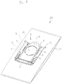
- FIG. 1 shows a dust container (20) for a vacuum cleaner.
- the dust container comprising a dust bag (21), made of an air permeable material, and a connector plate (10).
- the connector plate (10) surround an inlet (9) in the dust bag (21).
- the connector plate (10) is configured to correctly position the inlet (9) within a vacuum cleaner by the connector plate (10) being slid into a holder of the vacuum cleaner.
- the connector plate (10) comprising a front surface (5) having an opening (6) for an airflow.
- the opening (6) is positioned at the inlet (9) to the dust bag (21).
- the connector plate (10) also comprises a first side (1) adapted to be inserted into holder of a vacuum cleaner, and an opposite second side (2).
- the first side (1) is connecting the third (3) and fourth (4) sides.
- the connector plate also comprises two control apertures (7,8).
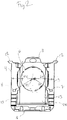
- the third side (3) and the forth side (4) are arranged at the same distance/radius (R1, R2) from the center of the opening (6), and two control apertures (7,8) are arranged at substantially the same distance/radius (R1, R2) from the center of the opening (6).
- the third side (3) is arranged at a first distances/radius (R1) from the center of the opening (6) and the forth side (4) is arranged at a second distance/radius (R2) from the center of the opening (6).
- At least a first of the control apertures (7) is arranged substantially at a first distance/radius (R1) from the center of the opening (6) and/or at least a second of the control apertures (8) is arranged substantially at a second distance (R2) from the center of the opening (6).
- Figure 1 and 2 shows a connector plate (10) with both control apertures (7,8) arranged in the area between the opening (6) and the first side (1).
- both control apertures (7,8) are arranged in the area between the opening (6) and the first side (1).
- Figure 1 and 2 shows a connector plate (10) comprising a first control apertures (7) arranged in the area between the opening (6) and the third side (3), and a second control aperture (8) arranged in the area between the opening (6) and the forth side (4).
- Figure 1 shows that the control apertures (7,8) comprises a hole through the connector plate (10).
- the first side (1) comprises a rigid part connecting the third (3) and fourth sides (4).
- the first side (1) also defines the part of the connector plate (10) furthest away from the opening (6).
- Figures 1 and 2 shows that the second side surface (2) is arranged closer to the opening (6) than the first side surface (1).
- the connector plate (10) comprises a flexible zone (13) arranged between the opening (6) and the first surface (1), the flexible zone (13) is flexible about an axis parallel to the first side surface (1).
- the flexible zone (13) a part of the connector plate may be bent into a curved shape.
- the flexible zone (13) is arranged so that the area around the opening (6) may remain flat when bending the flexible zone (13). This facilitates the connection to the inlet hose of the vacuum cleaner.
- the flexible zone (13) may be configured to be more easily bent backwards, towards the dust bag, as this is how the connector plate would best fit inside a vacuum cleaner.
- the flexibility can be accomplished by for example living hinges or perforation.
- Figure 1 and 2 shows a handle (11) arranged on the second side (2).
- a tab (12) is also arranged on the second side (2), the tab (12) is extending sideways outside the third (3) and/or forth side (4).
- the shutter (14) can be used to close the opening (6), and thereby the inlet (9), once the dust container (20) is full and is to be replaced. As the shutter (14) substantially seals the opening (6), it can be prevented to a great extent that collected dust leaks out of the dust bag when handled to be disposed.
- the shutter (14) can be slid upwards in fig 2 , away from the first side (1), such that the shutter moves over the dust bag inlet (9), thereby effectively closing this inlet.
- the connector plate may be made of for example polypropylene or paper.
- Figure 3 and 3a shows a vacuum cleaner (22).
- the connector plate (10) may be slide into a holder (23) in the vacuum cleaner (22).
- the third side (3) and fourth side (4) both being adapted to slide in a holder (23) of a vacuum cleaner.
- the first side (1) of the connector plate is first inserted into the holder (23).
- the holder (23) of a vacuum cleaner may be fixed inside the vacuum cleaner or may be removable.
- the holder (23) may comprise a holding element (24), such as a hook or pin (24), adapted to secure the dust container during use.
- the holding element (24) engage with at least one, preferably both, of the control apertures (7,8). This can be done by inserting the holding element (24) into one or both of the control aperture (7,8). Preferably holding elements (24) are engaging with both control aperture to get a reliable connection.
- the holding element disengage with the control apertures (7,8) at a certain force, for example by spring loaded holding elements, or snap function. Or the holding elements are automatically or manually disconnected from the control apertures (7,8).
- a holder (23) for a dust container comprises a sensor element, such as a light sensor, or mechanical sensor.
- the sensor element (24) could be a mechanical sensor such as a hook or pin (24), which snap into one or both of the control apertures (7,8) when the connector plate (10) is inserted into the holder. Such sensor could then inform the vacuum cleaner that a correct dust container is installed.
- the sensor element is a light sensor comprising a light emitter arranged on one side or the connector plate and a sensor on the other side. When the connection plate is correctly installed in the holder the light sensor can send a signal that the dust container is correctly installed in the holder.
- Light sensors can be arranged close to at least one, preferably both, of the control apertures (7,8).
Landscapes
- Engineering & Computer Science (AREA)
- Mechanical Engineering (AREA)
- Filters For Electric Vacuum Cleaners (AREA)
- Cleaning Implements For Floors, Carpets, Furniture, Walls, And The Like (AREA)
Abstract
Description
- The present disclosure relates to a dust container for a vacuum cleaner, the dust container comprising a dust bag, made of an air permeable material, and a connector plate, surrounding an inlet in the dust bag, such that the connector plate can correctly position the inlet within a vacuum cleaner by the connector plate being inserted in a holder of the vacuum cleaner.
- An example of such a container is disclosed for instance in
WO-02/24046-A1 - Further, the connector plate can trigger a feedback switch in the holder of the vacuum cleaner to verify that a dust container has been correctly installed in the holder, thus enabling the vacuum cleaner to prevent use in case of an absent or incorrectly installed dust container. Such use could otherwise damage the vacuum cleaner by injecting heavily dust laden air into a fan/motor arrangement.
- One problem associated with dust containers of this type is how to improve the securing of the dust bag to the vacuum cleaner during use and removal of the dust bag, and/or to have a more versatile way of sensing an absent or incorrectly installed dust container.
- An object of the present invention is to solve, or at least mitigate, this problem in the art. This object is achieved by means of a dust container as defined in
claim 1 and preceding claims. - A vacuum cleaner comprising the dust container is further envisaged.
- In an embodiment a dust container for a vacuum cleaner comprises a dust bag, made of an air permeable material, and a connector plate. The connector plate is surrounding an inlet in the dust bag. The connector plate is configured to correctly position the inlet within a vacuum cleaner by the connector plate being slid into a holder of the vacuum cleaner. The connector plate is comprising a front surface having an opening for an airflow. A first side adapted to be inserted into the holder of a vacuum cleaner, and an opposite second side. A third side is connecting the first and second sides, and a forth side is connecting the first and second sides. The first side is also connecting the third side and fourth side. The connector plate also comprises two control apertures.
- In an embodiment the third side is arranged at a first distance/radius from the center of the opening and the forth side is arranged at a second distance/radius from the center of the opening. At least one of the control apertures is/are arranged substantially at the first distance/radius from the center of the opening.
- In an embodiment at least one of the control apertures is/are arranged substantially at the second distance/radius from the center of the opening.
- In an embodiment the third side and the forth side are arranged at the same distance/radius from the center of the opening. The two control apertures, i.e. both first and second control apertures, are arranged at substantially the same distance/radius from the center of the opening.
- In an embodiment at least a part of both of the control apertures are arranged in the area between the opening and the first side.
- In an embodiment the first control aperture is arranged in an area between the opening and the third side. The second control aperture is arranged in an area between the opening and the forth side.
- In an embodiment the first and second control apertures comprises a hole through the connector plate.
- In an embodiment the first side comprises a rigid part connecting the third side and the fourth side.
- In an embodiment the second side is arranged closer to the opening than the first side.
- In an embodiment the connector plate comprises a flexible zone arranged between the opening and the first side. The flexible zone is flexible about an axis parallel to the first side.
- In an embodiment a handle is arranged on the second side.
- In an embodiment a tab is arranged on the second side, said tab is extending sideways outside the third and/or fourth sides.
- In an embodiment the third and fourth sides both being adapted to slide into a holder of a vacuum cleaner.
- In yet an embodiment a vacuum cleaner comprises a holder for a dust container. The vacuum cleaner also comprises a holding element, such as a hook or pin, adapted to secure the dust container during use. The holding element is securing the dust container through the connector plate, by engagement with at least one, preferably both, of the control apertures.
- In yet an embodiment a Vacuum cleaner comprises a holder for a dust container. The vacuum cleaner comprises also a sensor element, such as a light sensor, or mechanical sensor, adapted to secure that the dust container is correctly installed in the holder. The sensor element engaged with or through at least one, preferably both, of the control apertures.
-
- Fig 1
- shows a dust container for a vacuum cleaner.
- Fig 2
- shows a connector plate for a dust container.
- Fig 3
- shows a vacuum cleaner
- Fig 3a
- shows an enlargement of a portion of
Fig. 3 - The invention will now be described more fully hereinafter with reference to the accompanying drawings, in which certain embodiments of the invention are shown. This invention may, however, be embodied in many different forms and should not be construed as limited to the embodiments set forth herein; rather, these embodiments are provided by way of example so that this disclosure will be thorough and complete, and will fully convey the scope of the invention to those skilled in the art. Like numbers refer to like elements throughout the description.
-
Figure 1 shows a dust container (20) for a vacuum cleaner. The dust container comprising a dust bag (21), made of an air permeable material, and a connector plate (10). The connector plate (10) surround an inlet (9) in the dust bag (21). The connector plate (10) is configured to correctly position the inlet (9) within a vacuum cleaner by the connector plate (10) being slid into a holder of the vacuum cleaner. The connector plate (10) comprising a front surface (5) having an opening (6) for an airflow. The opening (6) is positioned at the inlet (9) to the dust bag (21). The connector plate (10) also comprises a first side (1) adapted to be inserted into holder of a vacuum cleaner, and an opposite second side (2). A third side (3) connecting the first and second sides, and a forth side (4) connecting the first and second sides. The first side (1) is connecting the third (3) and fourth (4) sides. The connector plate also comprises two control apertures (7,8). - In the
Figure 1 and2 the third side (3) and the forth side (4) are arranged at the same distance/radius (R1, R2) from the center of the opening (6), and two control apertures (7,8) are arranged at substantially the same distance/radius (R1, R2) from the center of the opening (6). - Alternatively, the third side (3) is arranged at a first distances/radius (R1) from the center of the opening (6) and the forth side (4) is arranged at a second distance/radius (R2) from the center of the opening (6). At least a first of the control apertures (7) is arranged substantially at a first distance/radius (R1) from the center of the opening (6) and/or at least a second of the control apertures (8) is arranged substantially at a second distance (R2) from the center of the opening (6).
-
Figure 1 and2 shows a connector plate (10) with both control apertures (7,8) arranged in the area between the opening (6) and the first side (1). Alternatively at least a part of both of the control apertures (7,8) are arranged in the area between the opening (6) and the first side (1). -
Figure 1 and2 shows a connector plate (10) comprising a first control apertures (7) arranged in the area between the opening (6) and the third side (3), and a second control aperture (8) arranged in the area between the opening (6) and the forth side (4). -
Figure 1 shows that the control apertures (7,8) comprises a hole through the connector plate (10). The first side (1) comprises a rigid part connecting the third (3) and fourth sides (4). The first side (1) also defines the part of the connector plate (10) furthest away from the opening (6). -
Figures 1 and2 shows that the second side surface (2) is arranged closer to the opening (6) than the first side surface (1). The connector plate (10) comprises a flexible zone (13) arranged between the opening (6) and the first surface (1), the flexible zone (13) is flexible about an axis parallel to the first side surface (1). - With the flexible zone (13) a part of the connector plate may be bent into a curved shape. The flexible zone (13) is arranged so that the area around the opening (6) may remain flat when bending the flexible zone (13). This facilitates the connection to the inlet hose of the vacuum cleaner.
- Typically, the flexible zone (13) may be configured to be more easily bent backwards, towards the dust bag, as this is how the connector plate would best fit inside a vacuum cleaner. The flexibility can be accomplished by for example living hinges or perforation.
-
Figure 1 and2 shows a handle (11) arranged on the second side (2). A tab (12) is also arranged on the second side (2), the tab (12) is extending sideways outside the third (3) and/or forth side (4). There may be a shutter (14) on the connector plate. Generally, the shutter (14) can be used to close the opening (6), and thereby the inlet (9), once the dust container (20) is full and is to be replaced. As the shutter (14) substantially seals the opening (6), it can be prevented to a great extent that collected dust leaks out of the dust bag when handled to be disposed. - The shutter (14) can be slid upwards in
fig 2 , away from the first side (1), such that the shutter moves over the dust bag inlet (9), thereby effectively closing this inlet. - The connector plate may be made of for example polypropylene or paper.
-
Figure 3 and 3a shows a vacuum cleaner (22). The connector plate (10) may be slide into a holder (23) in the vacuum cleaner (22). The third side (3) and fourth side (4) both being adapted to slide in a holder (23) of a vacuum cleaner. The first side (1) of the connector plate is first inserted into the holder (23). - The holder (23) of a vacuum cleaner may be fixed inside the vacuum cleaner or may be removable. The holder (23) may comprise a holding element (24), such as a hook or pin (24), adapted to secure the dust container during use. The holding element (24) engage with at least one, preferably both, of the control apertures (7,8). This can be done by inserting the holding element (24) into one or both of the control aperture (7,8). Preferably holding elements (24) are engaging with both control aperture to get a reliable connection.
- When the dust container is removed the holding element disengage with the control apertures (7,8) at a certain force, for example by spring loaded holding elements, or snap function. Or the holding elements are automatically or manually disconnected from the control apertures (7,8).
- Alternatively a holder (23) for a dust container comprises a sensor element, such as a light sensor, or mechanical sensor. The sensor element (24) could be a mechanical sensor such as a hook or pin (24), which snap into one or both of the control apertures (7,8) when the connector plate (10) is inserted into the holder. Such sensor could then inform the vacuum cleaner that a correct dust container is installed. In another embodiment the sensor element is a light sensor comprising a light emitter arranged on one side or the connector plate and a sensor on the other side. When the connection plate is correctly installed in the holder the light sensor can send a signal that the dust container is correctly installed in the holder. Light sensors can be arranged close to at least one, preferably both, of the control apertures (7,8).
- The present disclosure is not limited to the examples described above, and may be varied and altered in different ways within the scope of the appended claims.
-
- 1.
- First side
- 2.
- Second side
- 3.
- Third side
- 4.
- Fourth side
- 5.
- Front surface
- 6.
- Opening
- 7.
- First control aperture
- 8.
- Second control aperture
- 9.
- Inlet
- 10.
- Connector plate
- 11.
- Handle
- 12.
- Tab
- 13.
- Flexible zone
- 14.
- Shutter
- 20.
- Dust container
- 21.
- Bag
- 22.
- Vacuum cleaner
- 23.
- Holder
- 24.
- Pin
Claims (15)
- Dust container (20) for a vacuum cleaner, the dust container comprising a dust bag (21), made of an air permeable material, and a connector plate (10), surrounding an inlet (9) in the dust bag (21), whereby the connector plate (10) is configured to correctly position the inlet (9) within a vacuum cleaner by the connector plate (10) being slid into a holder of the vacuum cleaner, said connector plate (10) comprising a front surface (5) having an opening (6) for an airflow, a first side (1) adapted to be inserted into the holder of a vacuum cleaner, an opposite second side (2), a third side (3) connecting the first and second sides, and a forth side (4) connecting the first and second sides, the first side (1) is connecting the third (3) side and fourth side (4), characterized by that the connector plate (10) comprises two control apertures (7,8).
- Dust container (20) according to claim 1, wherein the third side (3) is arranged at a first distance/radius (R1) from the center of the opening (6) and the forth side (4) is arranged at a second distance/radius (R2) from the center of the opening (6), and at least one of the control apertures (7,8) is arranged substantially at the first distance/radius (R1) from the center of the opening (6).
- Dust container (20) according to claim 2, wherein at least one of the control apertures (7.8) is arranged substantially at the second distance/radius (R2) from the center of the opening (6).
- Dust container (20) according to claim 1, wherein the third side (3) and the forth side (4) are arranged at the same distance/radius (R1,R2) from the center of the opening (6), and the two control apertures (7,8) are arranged at substantially the same distance/radius (R1, R2) from the center of the opening (6).
- Dust container (20) according to any of the claims 1-4, wherein at least a part of both of the control apertures (7,8) are arranged in the area between the opening (6) and the first side (1).
- Dust container (20) according to any of the claims 1-5, wherein the first of the control apertures (7) is arranged in an area between the opening (6) and the third side (3), and the second control aperture (8) is arranged in an area between the opening (6) and the forth side (4).
- Dust container (20) according to any of the claims 1-6, wherein the control apertures (7,8) comprises a hole through the connector plate (10).
- Dust container (20) according to any of the claims 1-7, wherein the first side (1) comprises a rigid part connecting the third side (3) and the fourth side (4).
- Dust container (20) according to any of the claims 1-8, wherein the second side (2) is arranged closer to the opening (6) than the first side (1).
- Dust container (20) according to any of the claims 1-9, wherein the connector plate (10) comprises a flexible zone (13) arranged between the opening (6) and the first side (1), said flexible zone (13) is flexible about an axis parallel to the first side (1).
- Dust container (20) according to any of the claims 1-10, wherein a handle (11) is arranged on the second side (2).
- Dust container (20) according to any of the claims 1-11, wherein a tab (12) is arranged on the second side (2), said tab (12) is extending sideways outside the third or fourth sides.
- Dust container (20) according to any of the claims 1-12, wherein the third and fourth sides both being adapted to slide into a holder of a vacuum cleaner.
- Vacuum cleaner (22) comprising a holder (23) for a dust container (20) according to any of the claims 1-13, wherein the vacuum cleaner comprises a holding element (24), such as a hook or pin (24), adapted to secure the dust container (20) during use, by engagement with at least one, preferably both, of the control apertures (7,8).
- Vacuum cleaner (22) comprising a holder (23) for a dust container according to any of the claims 1-13, wherein the vacuum cleaner comprises a sensor element, such as a light sensor, or mechanical sensor, adapted to secure that the dust container is correctly installed in the holder, by use of at least one, preferably both, of the control apertures (7,8).
Priority Applications (7)
| Application Number | Priority Date | Filing Date | Title |
|---|---|---|---|
| HUE16200150A HUE063929T2 (en) | 2016-11-23 | 2016-11-23 | Dust container for a vacuum cleaner |
| EP16200150.7A EP3326506B1 (en) | 2016-11-23 | 2016-11-23 | Dust container for a vacuum cleaner |
| DK16200150.7T DK3326506T3 (en) | 2016-11-23 | 2016-11-23 | DUST CONTAINER FOR VACUUM CLEANERS |
| FIEP16200150.7T FI3326506T3 (en) | 2016-11-23 | 2016-11-23 | Dust container for a vacuum cleaner |
| PL16200150.7T PL3326506T3 (en) | 2016-11-23 | 2016-11-23 | Dust container for a vacuum cleaner |
| CN201711164115.4A CN108078492A (en) | 2016-11-23 | 2017-11-21 | For the dust receptacle of vacuum cleaner |
| RU2017140528A RU2763228C2 (en) | 2016-11-23 | 2017-11-22 | Dust collector for vacuum cleaner |
Applications Claiming Priority (1)
| Application Number | Priority Date | Filing Date | Title |
|---|---|---|---|
| EP16200150.7A EP3326506B1 (en) | 2016-11-23 | 2016-11-23 | Dust container for a vacuum cleaner |
Publications (2)
| Publication Number | Publication Date |
|---|---|
| EP3326506A1 true EP3326506A1 (en) | 2018-05-30 |
| EP3326506B1 EP3326506B1 (en) | 2023-08-16 |
Family
ID=57391851
Family Applications (1)
| Application Number | Title | Priority Date | Filing Date |
|---|---|---|---|
| EP16200150.7A Active EP3326506B1 (en) | 2016-11-23 | 2016-11-23 | Dust container for a vacuum cleaner |
Country Status (7)
| Country | Link |
|---|---|
| EP (1) | EP3326506B1 (en) |
| CN (1) | CN108078492A (en) |
| DK (1) | DK3326506T3 (en) |
| FI (1) | FI3326506T3 (en) |
| HU (1) | HUE063929T2 (en) |
| PL (1) | PL3326506T3 (en) |
| RU (1) | RU2763228C2 (en) |
Cited By (4)
| Publication number | Priority date | Publication date | Assignee | Title |
|---|---|---|---|---|
| USD975391S1 (en) * | 2022-04-28 | 2023-01-10 | Shenzhen Kuajingjianbing E-Commerce Co., Ltd | Vacuum bag cover |
| USD989429S1 (en) * | 2023-02-21 | 2023-06-13 | Dongguan Huaying Zhizao Co., Ltd. | Dust bag |
| USD996752S1 (en) * | 2022-01-29 | 2023-08-22 | Beijing Roborock Technology Co., Ltd. | Dust bag clamp for cleaning appliance |
| WO2025195589A1 (en) * | 2024-03-20 | 2025-09-25 | Miele & Cie. Kg | Device for holding a vacuum cleaner filter bag in a vacuum cleaner, and holding plate for a vacuum cleaner filter bag |
Families Citing this family (1)
| Publication number | Priority date | Publication date | Assignee | Title |
|---|---|---|---|---|
| CN111067418A (en) * | 2018-10-19 | 2020-04-28 | 德国福维克控股公司 | Dust filtering bag |
Citations (4)
| Publication number | Priority date | Publication date | Assignee | Title |
|---|---|---|---|---|
| EP0790030A1 (en) * | 1996-02-16 | 1997-08-20 | Branofilter Gmbh | Detection device for filter bag in suction cleaner |
| WO2002024046A1 (en) | 2000-09-22 | 2002-03-28 | Aktiebolaget Electrolux | Dust container for a vacuum cleaner |
| DE102005041811A1 (en) * | 2005-09-02 | 2007-03-08 | BSH Bosch und Siemens Hausgeräte GmbH | Vacuum cleaner bag with plastic flange |
| US20090089966A1 (en) * | 2007-10-08 | 2009-04-09 | Ian Emil Sohn | Vacuum Cleaner Bag Mounting Structure |
Family Cites Families (4)
| Publication number | Priority date | Publication date | Assignee | Title |
|---|---|---|---|---|
| DE3833799C2 (en) * | 1988-10-05 | 1994-10-06 | Licentia Gmbh | Vacuum cleaner with a filter |
| WO2002024047A1 (en) * | 2000-09-22 | 2002-03-28 | Aktiebolaget Electrolux | Dust container for a vacuum cleaner |
| DE202006016789U1 (en) * | 2006-11-03 | 2006-12-28 | Branofilter Gmbh | Connecting piece for vacuum cleaner dust filter bag has closure part with protruding region curved to side of bag in open position, shaped to produce essentially flat profile when moved to closing position by interaction with guide |
| US9074622B2 (en) * | 2011-11-03 | 2015-07-07 | Techtronic Floor Care Technology Limited | Disposable bag and a disposable bag mount bracket for an upright vacuum cleaner |
-
2016
- 2016-11-23 FI FIEP16200150.7T patent/FI3326506T3/en active
- 2016-11-23 DK DK16200150.7T patent/DK3326506T3/en active
- 2016-11-23 PL PL16200150.7T patent/PL3326506T3/en unknown
- 2016-11-23 EP EP16200150.7A patent/EP3326506B1/en active Active
- 2016-11-23 HU HUE16200150A patent/HUE063929T2/en unknown
-
2017
- 2017-11-21 CN CN201711164115.4A patent/CN108078492A/en active Pending
- 2017-11-22 RU RU2017140528A patent/RU2763228C2/en active
Patent Citations (4)
| Publication number | Priority date | Publication date | Assignee | Title |
|---|---|---|---|---|
| EP0790030A1 (en) * | 1996-02-16 | 1997-08-20 | Branofilter Gmbh | Detection device for filter bag in suction cleaner |
| WO2002024046A1 (en) | 2000-09-22 | 2002-03-28 | Aktiebolaget Electrolux | Dust container for a vacuum cleaner |
| DE102005041811A1 (en) * | 2005-09-02 | 2007-03-08 | BSH Bosch und Siemens Hausgeräte GmbH | Vacuum cleaner bag with plastic flange |
| US20090089966A1 (en) * | 2007-10-08 | 2009-04-09 | Ian Emil Sohn | Vacuum Cleaner Bag Mounting Structure |
Cited By (4)
| Publication number | Priority date | Publication date | Assignee | Title |
|---|---|---|---|---|
| USD996752S1 (en) * | 2022-01-29 | 2023-08-22 | Beijing Roborock Technology Co., Ltd. | Dust bag clamp for cleaning appliance |
| USD975391S1 (en) * | 2022-04-28 | 2023-01-10 | Shenzhen Kuajingjianbing E-Commerce Co., Ltd | Vacuum bag cover |
| USD989429S1 (en) * | 2023-02-21 | 2023-06-13 | Dongguan Huaying Zhizao Co., Ltd. | Dust bag |
| WO2025195589A1 (en) * | 2024-03-20 | 2025-09-25 | Miele & Cie. Kg | Device for holding a vacuum cleaner filter bag in a vacuum cleaner, and holding plate for a vacuum cleaner filter bag |
Also Published As
| Publication number | Publication date |
|---|---|
| CN108078492A (en) | 2018-05-29 |
| RU2763228C2 (en) | 2021-12-28 |
| FI3326506T3 (en) | 2023-11-08 |
| RU2017140528A3 (en) | 2021-02-17 |
| EP3326506B1 (en) | 2023-08-16 |
| DK3326506T3 (en) | 2023-11-13 |
| RU2017140528A (en) | 2019-05-22 |
| HUE063929T2 (en) | 2024-02-28 |
| PL3326506T3 (en) | 2024-02-19 |
Similar Documents
| Publication | Publication Date | Title |
|---|---|---|
| EP3326506B1 (en) | Dust container for a vacuum cleaner | |
| US10952581B2 (en) | Connector plate for a vacuum cleaner dust container and a dust container | |
| EP3884833B1 (en) | Dust container for a vacuum cleaner | |
| EP4074234B1 (en) | Devices of a vacuum cleaner dust container | |
| CN113974486B (en) | Connection plate for dust container of vacuum cleaner | |
| EP3454711B1 (en) | Dust container for a vacuum cleaner | |
| EP3544478B1 (en) | Holder for vacuum cleaner dust container | |
| EP3454713B1 (en) | Method for producing a dust container, and a connector plate thereof | |
| EP3791766B1 (en) | Versatile dust container for a vacuum cleaner | |
| NZ752487B2 (en) | Holder for vacuum cleaner dust container | |
| NZ746830B2 (en) | Connector plate for a vacuum cleaner dust container and a dust container |
Legal Events
| Date | Code | Title | Description |
|---|---|---|---|
| PUAI | Public reference made under article 153(3) epc to a published international application that has entered the european phase |
Free format text: ORIGINAL CODE: 0009012 |
|
| STAA | Information on the status of an ep patent application or granted ep patent |
Free format text: STATUS: THE APPLICATION HAS BEEN PUBLISHED |
|
| AK | Designated contracting states |
Kind code of ref document: A1 Designated state(s): AL AT BE BG CH CY CZ DE DK EE ES FI FR GB GR HR HU IE IS IT LI LT LU LV MC MK MT NL NO PL PT RO RS SE SI SK SM TR |
|
| AX | Request for extension of the european patent |
Extension state: BA ME |
|
| STAA | Information on the status of an ep patent application or granted ep patent |
Free format text: STATUS: REQUEST FOR EXAMINATION WAS MADE |
|
| 17P | Request for examination filed |
Effective date: 20181130 |
|
| RBV | Designated contracting states (corrected) |
Designated state(s): AL AT BE BG CH CY CZ DE DK EE ES FI FR GB GR HR HU IE IS IT LI LT LU LV MC MK MT NL NO PL PT RO RS SE SI SK SM TR |
|
| TPAC | Observations filed by third parties |
Free format text: ORIGINAL CODE: EPIDOSNTIPA |
|
| STAA | Information on the status of an ep patent application or granted ep patent |
Free format text: STATUS: EXAMINATION IS IN PROGRESS |
|
| 17Q | First examination report despatched |
Effective date: 20200703 |
|
| GRAP | Despatch of communication of intention to grant a patent |
Free format text: ORIGINAL CODE: EPIDOSNIGR1 |
|
| STAA | Information on the status of an ep patent application or granted ep patent |
Free format text: STATUS: GRANT OF PATENT IS INTENDED |
|
| INTG | Intention to grant announced |
Effective date: 20230405 |
|
| GRAS | Grant fee paid |
Free format text: ORIGINAL CODE: EPIDOSNIGR3 |
|
| GRAA | (expected) grant |
Free format text: ORIGINAL CODE: 0009210 |
|
| STAA | Information on the status of an ep patent application or granted ep patent |
Free format text: STATUS: THE PATENT HAS BEEN GRANTED |
|
| P01 | Opt-out of the competence of the unified patent court (upc) registered |
Effective date: 20230616 |
|
| AK | Designated contracting states |
Kind code of ref document: B1 Designated state(s): AL AT BE BG CH CY CZ DE DK EE ES FI FR GB GR HR HU IE IS IT LI LT LU LV MC MK MT NL NO PL PT RO RS SE SI SK SM TR |
|
| REG | Reference to a national code |
Ref country code: GB Ref legal event code: FG4D |
|
| REG | Reference to a national code |
Ref country code: CH Ref legal event code: EP |
|
| REG | Reference to a national code |
Ref country code: DE Ref legal event code: R096 Ref document number: 602016081929 Country of ref document: DE |
|
| REG | Reference to a national code |
Ref country code: IE Ref legal event code: FG4D |
|
| REG | Reference to a national code |
Ref country code: FI Ref legal event code: FGE |
|
| REG | Reference to a national code |
Ref country code: DK Ref legal event code: T3 Effective date: 20231110 |
|
| REG | Reference to a national code |
Ref country code: NL Ref legal event code: FP |
|
| REG | Reference to a national code |
Ref country code: SE Ref legal event code: TRGR |
|
| REG | Reference to a national code |
Ref country code: LT Ref legal event code: MG9D |
|
| REG | Reference to a national code |
Ref country code: AT Ref legal event code: MK05 Ref document number: 1599179 Country of ref document: AT Kind code of ref document: T Effective date: 20230816 |
|
| PG25 | Lapsed in a contracting state [announced via postgrant information from national office to epo] |
Ref country code: GR Free format text: LAPSE BECAUSE OF FAILURE TO SUBMIT A TRANSLATION OF THE DESCRIPTION OR TO PAY THE FEE WITHIN THE PRESCRIBED TIME-LIMIT Effective date: 20231117 |
|
| PG25 | Lapsed in a contracting state [announced via postgrant information from national office to epo] |
Ref country code: IS Free format text: LAPSE BECAUSE OF FAILURE TO SUBMIT A TRANSLATION OF THE DESCRIPTION OR TO PAY THE FEE WITHIN THE PRESCRIBED TIME-LIMIT Effective date: 20231216 |
|
| PG25 | Lapsed in a contracting state [announced via postgrant information from national office to epo] |
Ref country code: RS Free format text: LAPSE BECAUSE OF FAILURE TO SUBMIT A TRANSLATION OF THE DESCRIPTION OR TO PAY THE FEE WITHIN THE PRESCRIBED TIME-LIMIT Effective date: 20230816 Ref country code: PT Free format text: LAPSE BECAUSE OF FAILURE TO SUBMIT A TRANSLATION OF THE DESCRIPTION OR TO PAY THE FEE WITHIN THE PRESCRIBED TIME-LIMIT Effective date: 20231218 Ref country code: NO Free format text: LAPSE BECAUSE OF FAILURE TO SUBMIT A TRANSLATION OF THE DESCRIPTION OR TO PAY THE FEE WITHIN THE PRESCRIBED TIME-LIMIT Effective date: 20231116 Ref country code: LV Free format text: LAPSE BECAUSE OF FAILURE TO SUBMIT A TRANSLATION OF THE DESCRIPTION OR TO PAY THE FEE WITHIN THE PRESCRIBED TIME-LIMIT Effective date: 20230816 Ref country code: LT Free format text: LAPSE BECAUSE OF FAILURE TO SUBMIT A TRANSLATION OF THE DESCRIPTION OR TO PAY THE FEE WITHIN THE PRESCRIBED TIME-LIMIT Effective date: 20230816 Ref country code: IS Free format text: LAPSE BECAUSE OF FAILURE TO SUBMIT A TRANSLATION OF THE DESCRIPTION OR TO PAY THE FEE WITHIN THE PRESCRIBED TIME-LIMIT Effective date: 20231216 Ref country code: HR Free format text: LAPSE BECAUSE OF FAILURE TO SUBMIT A TRANSLATION OF THE DESCRIPTION OR TO PAY THE FEE WITHIN THE PRESCRIBED TIME-LIMIT Effective date: 20230816 Ref country code: GR Free format text: LAPSE BECAUSE OF FAILURE TO SUBMIT A TRANSLATION OF THE DESCRIPTION OR TO PAY THE FEE WITHIN THE PRESCRIBED TIME-LIMIT Effective date: 20231117 Ref country code: AT Free format text: LAPSE BECAUSE OF FAILURE TO SUBMIT A TRANSLATION OF THE DESCRIPTION OR TO PAY THE FEE WITHIN THE PRESCRIBED TIME-LIMIT Effective date: 20230816 |
|
| REG | Reference to a national code |
Ref country code: HU Ref legal event code: AG4A Ref document number: E063929 Country of ref document: HU |
|
| PG25 | Lapsed in a contracting state [announced via postgrant information from national office to epo] |
Ref country code: ES Free format text: LAPSE BECAUSE OF FAILURE TO SUBMIT A TRANSLATION OF THE DESCRIPTION OR TO PAY THE FEE WITHIN THE PRESCRIBED TIME-LIMIT Effective date: 20230816 |
|
| PG25 | Lapsed in a contracting state [announced via postgrant information from national office to epo] |
Ref country code: SM Free format text: LAPSE BECAUSE OF FAILURE TO SUBMIT A TRANSLATION OF THE DESCRIPTION OR TO PAY THE FEE WITHIN THE PRESCRIBED TIME-LIMIT Effective date: 20230816 Ref country code: RO Free format text: LAPSE BECAUSE OF FAILURE TO SUBMIT A TRANSLATION OF THE DESCRIPTION OR TO PAY THE FEE WITHIN THE PRESCRIBED TIME-LIMIT Effective date: 20230816 Ref country code: ES Free format text: LAPSE BECAUSE OF FAILURE TO SUBMIT A TRANSLATION OF THE DESCRIPTION OR TO PAY THE FEE WITHIN THE PRESCRIBED TIME-LIMIT Effective date: 20230816 Ref country code: EE Free format text: LAPSE BECAUSE OF FAILURE TO SUBMIT A TRANSLATION OF THE DESCRIPTION OR TO PAY THE FEE WITHIN THE PRESCRIBED TIME-LIMIT Effective date: 20230816 Ref country code: CZ Free format text: LAPSE BECAUSE OF FAILURE TO SUBMIT A TRANSLATION OF THE DESCRIPTION OR TO PAY THE FEE WITHIN THE PRESCRIBED TIME-LIMIT Effective date: 20230816 Ref country code: SK Free format text: LAPSE BECAUSE OF FAILURE TO SUBMIT A TRANSLATION OF THE DESCRIPTION OR TO PAY THE FEE WITHIN THE PRESCRIBED TIME-LIMIT Effective date: 20230816 |
|
| REG | Reference to a national code |
Ref country code: DE Ref legal event code: R097 Ref document number: 602016081929 Country of ref document: DE |
|
| PLBE | No opposition filed within time limit |
Free format text: ORIGINAL CODE: 0009261 |
|
| STAA | Information on the status of an ep patent application or granted ep patent |
Free format text: STATUS: NO OPPOSITION FILED WITHIN TIME LIMIT |
|
| PG25 | Lapsed in a contracting state [announced via postgrant information from national office to epo] |
Ref country code: MC Free format text: LAPSE BECAUSE OF FAILURE TO SUBMIT A TRANSLATION OF THE DESCRIPTION OR TO PAY THE FEE WITHIN THE PRESCRIBED TIME-LIMIT Effective date: 20230816 |
|
| PG25 | Lapsed in a contracting state [announced via postgrant information from national office to epo] |
Ref country code: LU Free format text: LAPSE BECAUSE OF NON-PAYMENT OF DUE FEES Effective date: 20231123 |
|
| 26N | No opposition filed |
Effective date: 20240517 |
|
| GBPC | Gb: european patent ceased through non-payment of renewal fee |
Effective date: 20231123 |
|
| PG25 | Lapsed in a contracting state [announced via postgrant information from national office to epo] |
Ref country code: MC Free format text: LAPSE BECAUSE OF FAILURE TO SUBMIT A TRANSLATION OF THE DESCRIPTION OR TO PAY THE FEE WITHIN THE PRESCRIBED TIME-LIMIT Effective date: 20230816 Ref country code: LU Free format text: LAPSE BECAUSE OF NON-PAYMENT OF DUE FEES Effective date: 20231123 Ref country code: IT Free format text: LAPSE BECAUSE OF FAILURE TO SUBMIT A TRANSLATION OF THE DESCRIPTION OR TO PAY THE FEE WITHIN THE PRESCRIBED TIME-LIMIT Effective date: 20230816 Ref country code: SI Free format text: LAPSE BECAUSE OF FAILURE TO SUBMIT A TRANSLATION OF THE DESCRIPTION OR TO PAY THE FEE WITHIN THE PRESCRIBED TIME-LIMIT Effective date: 20230816 |
|
| REG | Reference to a national code |
Ref country code: IE Ref legal event code: MM4A |
|
| PG25 | Lapsed in a contracting state [announced via postgrant information from national office to epo] |
Ref country code: IE Free format text: LAPSE BECAUSE OF NON-PAYMENT OF DUE FEES Effective date: 20231123 |
|
| PG25 | Lapsed in a contracting state [announced via postgrant information from national office to epo] |
Ref country code: GB Free format text: LAPSE BECAUSE OF NON-PAYMENT OF DUE FEES Effective date: 20231123 |
|
| PG25 | Lapsed in a contracting state [announced via postgrant information from national office to epo] |
Ref country code: IE Free format text: LAPSE BECAUSE OF NON-PAYMENT OF DUE FEES Effective date: 20231123 Ref country code: GB Free format text: LAPSE BECAUSE OF NON-PAYMENT OF DUE FEES Effective date: 20231123 |
|
| PG25 | Lapsed in a contracting state [announced via postgrant information from national office to epo] |
Ref country code: BG Free format text: LAPSE BECAUSE OF FAILURE TO SUBMIT A TRANSLATION OF THE DESCRIPTION OR TO PAY THE FEE WITHIN THE PRESCRIBED TIME-LIMIT Effective date: 20230816 |
|
| PG25 | Lapsed in a contracting state [announced via postgrant information from national office to epo] |
Ref country code: BG Free format text: LAPSE BECAUSE OF FAILURE TO SUBMIT A TRANSLATION OF THE DESCRIPTION OR TO PAY THE FEE WITHIN THE PRESCRIBED TIME-LIMIT Effective date: 20230816 |
|
| PG25 | Lapsed in a contracting state [announced via postgrant information from national office to epo] |
Ref country code: CY Free format text: LAPSE BECAUSE OF FAILURE TO SUBMIT A TRANSLATION OF THE DESCRIPTION OR TO PAY THE FEE WITHIN THE PRESCRIBED TIME-LIMIT; INVALID AB INITIO Effective date: 20161123 |
|
| REG | Reference to a national code |
Ref country code: CH Ref legal event code: U11 Free format text: ST27 STATUS EVENT CODE: U-0-0-U10-U11 (AS PROVIDED BY THE NATIONAL OFFICE) Effective date: 20251201 |
|
| PG25 | Lapsed in a contracting state [announced via postgrant information from national office to epo] |
Ref country code: TR Free format text: LAPSE BECAUSE OF FAILURE TO SUBMIT A TRANSLATION OF THE DESCRIPTION OR TO PAY THE FEE WITHIN THE PRESCRIBED TIME-LIMIT Effective date: 20230816 |
|
| PGFP | Annual fee paid to national office [announced via postgrant information from national office to epo] |
Ref country code: HU Payment date: 20251121 Year of fee payment: 10 |
|
| PGFP | Annual fee paid to national office [announced via postgrant information from national office to epo] |
Ref country code: NL Payment date: 20251124 Year of fee payment: 10 |
|
| PGFP | Annual fee paid to national office [announced via postgrant information from national office to epo] |
Ref country code: DE Payment date: 20251126 Year of fee payment: 10 |
|
| PGFP | Annual fee paid to national office [announced via postgrant information from national office to epo] |
Ref country code: FI Payment date: 20251124 Year of fee payment: 10 Ref country code: DK Payment date: 20251124 Year of fee payment: 10 |
|
| PGFP | Annual fee paid to national office [announced via postgrant information from national office to epo] |
Ref country code: FR Payment date: 20251124 Year of fee payment: 10 |
|
| PGFP | Annual fee paid to national office [announced via postgrant information from national office to epo] |
Ref country code: BE Payment date: 20251124 Year of fee payment: 10 |
|
| PGFP | Annual fee paid to national office [announced via postgrant information from national office to epo] |
Ref country code: CH Payment date: 20251201 Year of fee payment: 10 Ref country code: SE Payment date: 20251124 Year of fee payment: 10 |
|
| PGFP | Annual fee paid to national office [announced via postgrant information from national office to epo] |
Ref country code: PL Payment date: 20251114 Year of fee payment: 10 |