EP3326408B1 - Couche de convergence pour systèmes de communication 5g - Google Patents
Couche de convergence pour systèmes de communication 5g Download PDFInfo
- Publication number
- EP3326408B1 EP3326408B1 EP15823476.5A EP15823476A EP3326408B1 EP 3326408 B1 EP3326408 B1 EP 3326408B1 EP 15823476 A EP15823476 A EP 15823476A EP 3326408 B1 EP3326408 B1 EP 3326408B1
- Authority
- EP
- European Patent Office
- Prior art keywords
- ncp
- layer
- sdu
- pdu
- uplink
- Prior art date
- Legal status (The legal status is an assumption and is not a legal conclusion. Google has not performed a legal analysis and makes no representation as to the accuracy of the status listed.)
- Active
Links
- 238000004891 communication Methods 0.000 title claims description 70
- 238000000034 method Methods 0.000 claims description 80
- 230000008569 process Effects 0.000 claims description 38
- 230000004044 response Effects 0.000 claims description 35
- 238000012545 processing Methods 0.000 claims description 22
- 238000005516 engineering process Methods 0.000 claims description 18
- 230000005540 biological transmission Effects 0.000 description 21
- 239000002609 medium Substances 0.000 description 21
- 238000003860 storage Methods 0.000 description 21
- 230000006870 function Effects 0.000 description 17
- 241000700159 Rattus Species 0.000 description 13
- 230000001413 cellular effect Effects 0.000 description 7
- 238000003379 elimination reaction Methods 0.000 description 7
- 230000011664 signaling Effects 0.000 description 7
- 238000013507 mapping Methods 0.000 description 6
- 230000009977 dual effect Effects 0.000 description 5
- 230000008030 elimination Effects 0.000 description 5
- 239000000872 buffer Substances 0.000 description 4
- 238000004590 computer program Methods 0.000 description 4
- 238000010586 diagram Methods 0.000 description 4
- 230000007774 longterm Effects 0.000 description 4
- 238000005259 measurement Methods 0.000 description 4
- 238000001228 spectrum Methods 0.000 description 4
- 230000001360 synchronised effect Effects 0.000 description 4
- 238000012546 transfer Methods 0.000 description 4
- 230000001960 triggered effect Effects 0.000 description 4
- 230000009471 action Effects 0.000 description 3
- 230000003287 optical effect Effects 0.000 description 3
- 230000002776 aggregation Effects 0.000 description 2
- 238000004220 aggregation Methods 0.000 description 2
- 230000008859 change Effects 0.000 description 2
- 230000006835 compression Effects 0.000 description 2
- 238000007906 compression Methods 0.000 description 2
- 230000006837 decompression Effects 0.000 description 2
- 239000000835 fiber Substances 0.000 description 2
- 238000007726 management method Methods 0.000 description 2
- 238000004519 manufacturing process Methods 0.000 description 2
- 238000010295 mobile communication Methods 0.000 description 2
- 238000012986 modification Methods 0.000 description 2
- 230000004048 modification Effects 0.000 description 2
- 230000008520 organization Effects 0.000 description 2
- 101000741965 Homo sapiens Inactive tyrosine-protein kinase PRAG1 Proteins 0.000 description 1
- 102100038659 Inactive tyrosine-protein kinase PRAG1 Human genes 0.000 description 1
- 238000007792 addition Methods 0.000 description 1
- 238000013459 approach Methods 0.000 description 1
- 230000000712 assembly Effects 0.000 description 1
- 238000000429 assembly Methods 0.000 description 1
- 230000008901 benefit Effects 0.000 description 1
- 230000003139 buffering effect Effects 0.000 description 1
- 230000010267 cellular communication Effects 0.000 description 1
- 239000000470 constituent Substances 0.000 description 1
- 238000013479 data entry Methods 0.000 description 1
- 238000013500 data storage Methods 0.000 description 1
- 230000007812 deficiency Effects 0.000 description 1
- 238000011161 development Methods 0.000 description 1
- 230000005670 electromagnetic radiation Effects 0.000 description 1
- 238000005538 encapsulation Methods 0.000 description 1
- 238000013467 fragmentation Methods 0.000 description 1
- 238000006062 fragmentation reaction Methods 0.000 description 1
- 230000003116 impacting effect Effects 0.000 description 1
- 230000010354 integration Effects 0.000 description 1
- 230000003993 interaction Effects 0.000 description 1
- 239000004973 liquid crystal related substance Substances 0.000 description 1
- 229940052961 longrange Drugs 0.000 description 1
- 238000012423 maintenance Methods 0.000 description 1
- 230000007246 mechanism Effects 0.000 description 1
- 230000005055 memory storage Effects 0.000 description 1
- 238000012544 monitoring process Methods 0.000 description 1
- 230000000737 periodic effect Effects 0.000 description 1
- 230000010363 phase shift Effects 0.000 description 1
- 239000002096 quantum dot Substances 0.000 description 1
- 238000005070 sampling Methods 0.000 description 1
- 239000007787 solid Substances 0.000 description 1
- 230000007480 spreading Effects 0.000 description 1
- 238000003892 spreading Methods 0.000 description 1
- 238000011272 standard treatment Methods 0.000 description 1
- 230000002194 synthesizing effect Effects 0.000 description 1
- 239000010409 thin film Substances 0.000 description 1
- 230000009466 transformation Effects 0.000 description 1
- 238000000844 transformation Methods 0.000 description 1
- 230000007723 transport mechanism Effects 0.000 description 1
- 239000006163 transport media Substances 0.000 description 1
- 230000036642 wellbeing Effects 0.000 description 1
Images


Classifications
-
- H—ELECTRICITY
- H04—ELECTRIC COMMUNICATION TECHNIQUE
- H04L—TRANSMISSION OF DIGITAL INFORMATION, e.g. TELEGRAPHIC COMMUNICATION
- H04L45/00—Routing or path finding of packets in data switching networks
- H04L45/22—Alternate routing
-
- H—ELECTRICITY
- H04—ELECTRIC COMMUNICATION TECHNIQUE
- H04L—TRANSMISSION OF DIGITAL INFORMATION, e.g. TELEGRAPHIC COMMUNICATION
- H04L47/00—Traffic control in data switching networks
- H04L47/10—Flow control; Congestion control
- H04L47/34—Flow control; Congestion control ensuring sequence integrity, e.g. using sequence numbers
-
- H—ELECTRICITY
- H04—ELECTRIC COMMUNICATION TECHNIQUE
- H04W—WIRELESS COMMUNICATION NETWORKS
- H04W28/00—Network traffic management; Network resource management
- H04W28/02—Traffic management, e.g. flow control or congestion control
- H04W28/0273—Traffic management, e.g. flow control or congestion control adapting protocols for flow control or congestion control to wireless environment, e.g. adapting transmission control protocol [TCP]
-
- H—ELECTRICITY
- H04—ELECTRIC COMMUNICATION TECHNIQUE
- H04W—WIRELESS COMMUNICATION NETWORKS
- H04W28/00—Network traffic management; Network resource management
- H04W28/02—Traffic management, e.g. flow control or congestion control
- H04W28/08—Load balancing or load distribution
- H04W28/082—Load balancing or load distribution among bearers or channels
-
- H—ELECTRICITY
- H04—ELECTRIC COMMUNICATION TECHNIQUE
- H04W—WIRELESS COMMUNICATION NETWORKS
- H04W80/00—Wireless network protocols or protocol adaptations to wireless operation
- H04W80/02—Data link layer protocols
-
- H—ELECTRICITY
- H04—ELECTRIC COMMUNICATION TECHNIQUE
- H04W—WIRELESS COMMUNICATION NETWORKS
- H04W36/00—Hand-off or reselection arrangements
- H04W36/0005—Control or signalling for completing the hand-off
- H04W36/0055—Transmission or use of information for re-establishing the radio link
- H04W36/0066—Transmission or use of information for re-establishing the radio link of control information between different types of networks in order to establish a new radio link in the target network
-
- H—ELECTRICITY
- H04—ELECTRIC COMMUNICATION TECHNIQUE
- H04W—WIRELESS COMMUNICATION NETWORKS
- H04W36/00—Hand-off or reselection arrangements
- H04W36/0005—Control or signalling for completing the hand-off
- H04W36/0055—Transmission or use of information for re-establishing the radio link
- H04W36/0069—Transmission or use of information for re-establishing the radio link in case of dual connectivity, e.g. decoupled uplink/downlink
- H04W36/00698—Transmission or use of information for re-establishing the radio link in case of dual connectivity, e.g. decoupled uplink/downlink using different RATs
-
- H—ELECTRICITY
- H04—ELECTRIC COMMUNICATION TECHNIQUE
- H04W—WIRELESS COMMUNICATION NETWORKS
- H04W88/00—Devices specially adapted for wireless communication networks, e.g. terminals, base stations or access point devices
- H04W88/02—Terminal devices
- H04W88/06—Terminal devices adapted for operation in multiple networks or having at least two operational modes, e.g. multi-mode terminals
Definitions
- the present disclosure relates to wireless communications, and more specifically, to a convergence protocol layer for wireless communications.
- the fifth generation of mobile technology is positioned to address the demands and business contexts of 2020 and beyond. It has potential to enable a fully mobile and connected society and to empower socio-economic transformations in a countless number of ways, many of which are unimagined, including those for productivity, sustainability and well-being.
- the new radio access technology (RAT) to be introduced for 5G can be deployed in a high frequency band, e.g. millimeter wave (mmW), ranging from about 30GHz to about 300 GHz.
- a wireless device e.g., a user equipment (UE)
- UE user equipment
- One is channel condition or environment changes within a short time interval, which may last for tens of milliseconds.
- human blockage can be another with a duration that can last several hundreds of milliseconds, for example, or more or less.
- TCP transmission control protocol
- QoE quality of experience
- the node can be a combination of Evolved Universal Terrestrial Radio Access Network (EUTRAN) Node Bs (also commonly denoted as evolved Node Bs, enhanced Node Bs, eNodeBs, or eNBs) and Radio Network Controllers (RNCs), which communicates with the UE.
- EUTRAN Evolved Universal Terrestrial Radio Access Network
- Node Bs also commonly denoted as evolved Node Bs, enhanced Node Bs, eNodeBs, or eNBs
- RNCs Radio Network Controllers
- the downlink (DL) transmission can be a communication from the node (e.g., eNB) to the UE
- the uplink (UL) transmission can be a communication from the wireless device to the node.
- data can be transmitted from the eNodeB to the UE via a physical downlink shared channel (PDSCH).
- PDSCH physical downlink shared channel
- a physical uplink control channel can be used to acknowledge that data was received.
- Downlink and uplink channels can use time-division duplexing (TDD) or frequency-division duplexing (FDD).
- TDD time-division duplexing
- FDD frequency-division duplexing
- US 22015/006295 relates to user equipment relocation between nodes in a wireless communication system.
- a component can be a processor, a process running on a processor, a controller, a circuit or a circuit element, an object, an executable, a program, a storage device, a computer, a tablet PC and/or a mobile phone with a processing device.
- an application running on a server and the server can also be a component.
- One or more components can reside within a process, and a component can be localized on one computer and/or distributed between two or more computers.
- a set of elements or a set of other components can be described herein, in which the term “set” can be interpreted as "one or more.”
- these components can execute from various computer readable storage media having various data structures stored thereon such as with a module, for example.
- the components can communicate via local and/or remote processes such as in accordance with a signal having one or more data packets (e.g., data from one component interacting with another component in a local system, distributed system, and/or across a network, such as, the Internet, a local area network, a wide area network, or similar network with other systems via the signal).
- a signal having one or more data packets (e.g., data from one component interacting with another component in a local system, distributed system, and/or across a network, such as, the Internet, a local area network, a wide area network, or similar network with other systems via the signal).
- a component can be an apparatus with specific functionality provided by mechanical parts operated by electric or electronic circuitry, in which the electric or electronic circuitry can be operated by a software application or a firmware application executed by one or more processors.
- the one or more processors can be internal or external to the apparatus and can execute at least a part of the software or firmware application.
- a component can be an apparatus that provides specific functionality through electronic components or elements without mechanical parts; the electronic components can include one or more processors therein to execute software and/or firmware that confer(s), at least in part, the functionality of the electronic components.
- various process and network devices are discloses to facilitate packet communications with a network convergence protocol (NCP) layer without having to utilizing bearer switching as a result of a fallback operation or other change from one serving access node (access point or network device (ND)) serving a UE.
- NCP network convergence protocol
- such fallback operation can include changing the serving node from one radio access technology (RAT) (e.g., an LTE or 5GPP millimeter wave (mmW) to another (e.g., 5G mmW or other RAT) in response to various network conditions (e.g., blockage) that make the fallback target cell more optimal for the UE.
- RAT radio access technology
- mmW millimeter wave
- 5G mmW 5G mmW or other RAT
- HetNet heterogeneous networks
- HetNets anchor-booster based heterogeneous networks
- a network device e.g., an eNB, management entity, UE or any device communicatively coupled to a network
- the multi-radio HetNet can comprise various multi-radio connections of various RATs, such as 3GPP, LTE, 5G, mmW, legacy 3GPP RATs via one or more NDs.
- the network device can comprise a NCP layer that operates to reduce interruption time from blockage events by controlling retransmissions, reordering processes, and duplicate elimination / discarding operations in response to fallback operations or processes.
- the network device can include a memory with computer-executable components or instructions, and processing circuitry, communicatively coupled to the memory, which facilitates execution of the computer-executable components.
- the computer-executable components can include a receive logic component that receives, from a first layer (e.g., an upper or lower protocol layer), a first data unit or packet (e.g., a NCP protocol data unit (PDU) or a NCP service data unit (SDU)) that is associated with the NCP layer.
- PDU NCP protocol data unit
- SDU NCP service data unit
- the NCP layer can further control data unit / packet flow without bearer switching in response to fallback operations from a network device (e.g., an LTE or 5G anchor node or eNB) of the multi-radio heterogeneous network of the RAN.
- a network device e.g., an LTE or 5G anchor node or eNB
- a control logic component can generate a second data unit associated with the NCP layer based on the first data unit.
- a transmit logic component can transmit the second data unit to a second layer (e.g., a lower or upper protocol layer) that is different from and opposite in protocol level than the first layer.
- a second layer e.g., a lower or upper protocol layer
- the upper layer can be an internet protocol (IP) layer and the lower layer a packet data convergence protocol PDCP. Additional aspects and details of the disclosure are further described below with reference to figures.
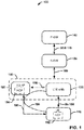
- FIG. 1 illustrates a 3GPP RAN anchor-booster 5G network architectures 100 for LTE-5G aggregation in accordance with various aspects or embodiments being described.
- the network architecture 100 can comprise an end-to-end network for cellular communications, including a UE 110, an eNB 120, and the following two gateway entities of an evolved packet core (EPC), or other network core, which are examples of network entities and can be extended to other network entities such as for 5G and beyond : a serving gateway (S-GW) 130 and a packet data network (PDN) gateway (PDN GW, or P-GW) 140, as well as other network entities or components, for example.
- EPC evolved packet core
- S-GW serving gateway
- PDN gateway packet data network gateway
- P-GW packet data network gateway
- an EPC can include other network entities and interfaces not further detailed such as for 5G networks or otherwise.
- the UE 110 can communicate with the eNB 120 through an air interface Uu 150 (also referred to as a cellular link), which can comprise a wireless radio communication channel defined in 3GPP standards for long term evolution (LTE) wireless networks.
- the UE 110 can also operate as a dual connected device or dual radio UE 110 by being communicatively coupled to a 5G interface 196 or one or more other communication links / interfaces on the network concurrently or at the same time.
- the S-GW 130 in communication with the eNB 120 through an interface 160 (e.g., an S1 or other interface), provides a point of interconnect between the wireless radio side and the EPC side of the network architecture 100, as a co-located or a non-collated eNB 120, in which "collocated” refers to the LTE AP (e.g., the eNB 120) being located in the same network device 199 or component as the 5G ND or AP 180.
- the interface 160 can also be connected separately and independently to both the LTE eNB 120 and the 5G AP 180.
- Network devices herein can be a gateway support node device, a cellular management entity device, a packet data gateway device, an eNB, for example, as well as other network devices functionally serving network communications for UEs and combinations of these devices communicatively coupled to one another.
- the S-GW 130 can comprise the anchor point for the intra-LTE mobility, i.e., in case of a handover between eNBs and between LTE and other 3GPP accesses.
- the S-GW 130 is logically connected to the other gateway, the P-GW 140, through an S5/8 interface 170.
- 3GPP standards specify separately the S-GW 130 and the P-GW 140, but in practice, these gateways can be combined as a common network component provided by a network equipment vendor.
- the P-GW 140 further provides a point of interconnect between the EPC and an external internet protocol (IP) network (not shown).
- IP internet protocol
- An external IP network is also called a packet data network (PDN).
- the P-GW 140 can route IP packets to and from PDNs.
- FIG. 1 further illustrates that the UE 110 can communicate with the eNB 120 through a 5G AP 180 via an interface 190, and can be connected to both the 5G AP 180 and the eNB 120 concurrently or simultaneously via interfaces 196 and 150, respectively.
- the interface 190 represents the operative network connection and protocols between the UE 110 and its associated LTE cellular base station (BS), the eNB 120.
- the interface 190 can be a logical interface that can be realized by a mmW point-to-point communication link between the UE 110 and the eNB 120 for routing the UE 110's cellular traffic (e.g., voice or data) via the 5G AP 180.
- BS LTE cellular base station
- the 5G AP 180 network device can comprise network convergence protocol (NCP) layer 194 while the UE device 110 can comprise an NCP layer 192.
- NCP network convergence protocol
- the NCP layers 194 or 192 can enable packet communications involving packet retransmission, reordering for out-of-sequence occurrences, or duplication removal/discard/elimination processes without having to utilize a different bearer as a result of a fallback operation from the LTE eNB 120 to the 5G AP 180, or vice versa.
- a bearer represents a class of traffic having a set of network parameters that establish a specific standard treatment for the traffic or data being communicated on the particular class of traffic (e.g., voice or the like) for one or more UEs or network devices (e.g., eNBs or the like). Bearers can be used to carry user plane traffic (i.e., user data) on an air interface, for example.
- the NCP layers 194 or 192 can decrease the amount of interruption experienced by providing a specialized protocol layer in the communication processing that detects such blockages based on one or more criteria including any network condition or measurement related to the frequency band, network device operating (communicating) on the frequency band, or channel conditions, such as a signal strength, a channel quality, a load condition of the ND, or other parameter such as a reference signal received power (RSRP), a reference signal received quality (RSRQ), channel state information (CSI), one or more channel quality indicators (CQIs) or the like.
- RSRP reference signal received power
- RSRQ reference signal received quality
- CSI channel state information
- CQIs channel quality indicators
- a fallback operation can occur where the NCP layer 192, 194 operates at a receiving side and a transmitting side, either at different NDs (e.g., the UE 110, the 5G AP 180, the LTE eNB 120, or other ND), or within the receive and transmit side circuitry components of each ND.
- LTE eNB 120 and 5G AP 180 new RAT can co-exist.
- the 3GPP interface can be used as the control and mobility anchor for the 5G link (e.g., 190 or 196), which can serve as an additional "carrier" within the 3GPP network and used for data offload.
- the interface link 198 can be a user plane or control plane protocol.
- the LTE eNB 120 can be configured for coverage (i.e. mobility), while the 5G AP 180 RAT can be used for data offloading (as known as anchor-booster architecture).
- anchor-booster architecture can be used for data offloading
- anchor-booster architecture can be used for data offloading
- both anchor and booster node can be one or more 5G access nodes.
- the bearer can be mapped to either the LTE eNB 120 or the 5G AP 180, where fallback to the LTE eNB would utilize explicit radio resource control (RRC) signaling to switch the bearer type, which could incur a long interruption time without the NCP layer 192 or 194 in operation.
- RRC radio resource control
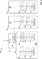
- an example network device 200 e.g., a UE, a eNB of either 5G or LTE, or other ND
- a network convergence protocol layer for 5G communication system integration in accordance with various aspects.
- Embodiments herein relate to the NCP layer 204 to enable blockage issues that can occur in high frequency bands of 5G wireless systems.
- the NCP layer 204 can control packet retransmission / reordering / duplicate removal processes that result from the fallback between a 5G ND and an LTE ND, for example.
- the TCP/IP layer 202 comprises a Transmission Control Protocol/Internet Protocol layers that is the basic communication language or protocol of the Internet, and can be used as a communications protocol in a private network (either an intranet or an extranet).
- the TCP/IP layer 202 facilitates communications protocols used to connect network devices on the Internet.
- the NCP layer 204 can be utilized to meet demand for faster data rates and prevent the incurrence of long interruption times by blockages occurring over one or more 5G ND 180.
- the 5G ND 180 can be used for data offloading in order to alleviate or enable efficient load balancing on the network.
- the NCP layer 204 can operate on the DL or UL to facilitate traffic operations such as retransmissions, reordering, or duplicate discarding/elimination processes without bearer switching. This can enable fallback to other nodes, such as from the 5G ND 180 to another 5G AP coupled thereat or the LTE ND 120, for example.
- the NCP layer 204 can be added can be added on top of or above one or more packet data convergence protocol (PDCP) layers 206, 206' (lower layer(s)) to perform IP packet retransmissions in either LTE eNB or another 5G node in case of blockage in one 5G node.
- PDCP packet data convergence protocol
- the NCP layer 204 could also have other names, such as a Hyper Convergence Protocol (HCP), a Node Convergence Protocol (NCP), a Multi-Node Convergence Protocol (MNCP), a Multi-Node Flow Control (MNFC), and is not limited to any one particular name for converging a 5G ND communications with an LTE ND 120 or UE 110.
- HCP Hyper Convergence Protocol
- NCP Node Convergence Protocol
- MNCP Multi-Node Convergence Protocol
- MNFC Multi-Node Flow Control
- the Packet Data Convergence Protocol (PDCP) layer(s) 206, 206' residing below or lower than the NCP layer 204 can be one of the layers of the Radio Traffic Stack in LTE, UMTS and can perform IP header compression and decompression, transfer of user data and maintenance of sequence numbers for Radio Bearers.
- PDCP Packet Data Convergence Protocol
- the radio link control (RLC) layer(s) 208, 208' below or lower than the PDCP layer(s) 206, 206' can handle an automatic repeat request fragmentation protocol used over a wireless air interface.
- the RLC can detect packet losses and perform various other retransmissions aside from fall back conditions from a 5G node controlled by the NCP layer 204 to bring packet loss down to a low percentage rate, which is suitable for TCP/IP applications.
- the physical (PHY) and MAC layers 210 and 214 can operate to provide an electrical, mechanical, and procedural interface to the transmission medium.
- the physical layer translates logical communications requests from the data link layer into hardware-specific operations to affect transmission or reception of electronic signals.
- the MAC sublayer provides addressing and channel access control mechanisms that make it possible for several terminals or network nodes to communicate within a multiple access network that incorporates a shared medium.
- FIG. 3 illustrates an example of a network 300 having various network devices (e.g., a UE, eNB of one or more of LTE/5G RATs).
- the network device 302 can be a serving node operating as a 5G mmW RAT node for downlinking data to a UE, for example.
- the network system 300 can utilize the NCP layer 204 for controlling fallback communications without bearer switching from a 5G mmW ND / node toward another 5G ND or LTE ND in response to a blockage being detected.
- the corresponding receiving side operation is further illustrated in FIG. 4 .
- Embodiments relate to how the bearer/packet flow handled by 5G node 302 can be enabled to fallback to other nodes (e.g., the in case there is blockage experienced in the 5G ND 302.
- the fallback operation can be performed in various directions such as towards the LTE or 5G ND 200, which can operate as the anchor node of the network 300.
- the fallback could also be performed towards another 5G node/ND 304.
- typically the 5G ND 304 can also be deployed in high frequency bands, and thus can provide similar throughput as 5G ND 302.
- the fallback operation could also be performed towards at least one of the LTE or 5G anchor node 200 and another 5G node (e.g., 5G ND 304).
- the NCP layer 204 could comprise a transmit logic component 306 for transmitting one or more packet or data units to lower layers of the protocol stack.
- the transmit logic component 306 as well as the NCP layer 204 could reside as part of logic within the protocol stack as well as integrated in the logic circuitry (transceiver, transmitter or receiver circuitry) of a respective network device (e.g., UE, LTE eNB, 5G eNB, or otherwise).
- the transmit logic component 402 in response to a reception of a NCP service data unit (SDU) from upper layers, process the NCP SDU and submit a resulting NCP layer PDU to a lower layer.
- SDU NCP service data unit
- FIG. 4 illustrates the NCP layer 204 comprising the transmit logic component 306 along with a receive logic component 402 for receiving and passing along packet or data units to upper or lower layers of the protocol stack.
- the receive logic component 402 can reside or operate at a receiving side, and in response to a reception of the NCP PDU from one or more lower layers, process the NCP PDU and deliver the resulting NCP layer SDU to an upper layer; in which as illustrated in FIG. 2 above, the upper layer 202 can be an Internet Protocol (IP) layer 202, and the lower layer can be PDCP layer 206 as a layer that resides immediately below the NCP layer 204.
- IP Internet Protocol
- the network environment 500 comprises an NCP layer component 504 that receives data from various different network devices as data traffic 502 from UEs 520-528, data traffic via interfaces 530-540 from one or more APs, eNBs, or other network devices or components of one or more different RATs.
- the NCP layer component 504 can include the TX logic component 306, and the RX logic component 204 as part of the NCP layer 204 across one or more NDs (e.g., eNBs, UEs or network entities).
- the NCP layer component 504 can be a part of the NCP layer 204 or vice versa.
- the NCP layer component 504 can enable the network environment 500 to be delay aware by detecting blockage at a 5G mmW node (e.g., ND 512) and operating retransmission processes / reordering processes / duplication removal process and the like among network devices 512-516 and the UEs 520-528 as the result of a fallback from a detected blockage.
- the UE e.g., 524 or otherwise
- the eNB 514 in connected mode or DL operations with the UE 524 can detect the blockage via a channel quality, SNR, a status report or other measurement or indication.
- a status report can be sent to the eNB 514 via the UE 524 at regular scheduled intervals, based on an event trigger (e.g., low channel quality, SNR, low power, etc.) or be sent based on upon request from the eNB 514.
- an event trigger e.g., low channel quality, SNR, low power, etc.
- the network devices 512-516 can comprise one or more WLAN network devices, eNBs, small cell network devices, routers or other network devices of different RATs configured to communicate with the various UEs 520-528 within one or more network zones for communication and managing operations.
- the network device 512 for example, can comprise a 5G mmW ND 512 with a base station queue 506 for buffering traffic thereat.
- the network device 514 for example, can comprise another 5G mmW ND with a buffer / queue 508.
- another network device 516 can comprise an LTE eNB or hybrid LTE/ 5G eNB anchor node with a base station queue 510.
- one or more additional or alternative base station RATs can also be coupled to or comprise the NCP convergence layer 204 with traffic buffers or queues thereat for offloading and downlinking data for traffic flow.
- Each UE 520-528 can be single or dual connected devices that are communicatively coupled to one or more communication links (e.g., license or unlicensed links) via one or more network devices or nodes (e.g., 5G 512 and eNB 516, or any other RAT network device) and can also be coupled to or comprise the NCP layer 204, for example.
- the network system 500 can include any number of base stations/access points/ RATs across which the traffic can be converged for each UE 520-528 for fallback operations involving a switch between a 5G ND, an LTE/5G node 516 ND and another ND or node.
- NCP layer component 504 can be located or reside at the eNB (e.g., 516) and other devices (e.g., NDs 512-514, and UEs 520-528) in cellular networks.
- the UEs 520-528 maintain the necessary parts related to the bearer (or IP data flow). For example, when fallback is performed towards the LTE / 5G anchor node 512 from the 5G node 514 or other 5G ND 512 as a result of a blockage condition, the UE 520-528 can maintain or store layer 2 protocols (e.g. PDCP/RLC/MAC) corresponding to the LTE / 5G anchor node, as well as layer 2 protocols corresponding to 5G ND 514.
- layer 2 protocols e.g. PDCP/RLC/MAC
- dynamic fallback without bearer mapping or switching can also be facilitated when fallback is performed towards another 5G node 512 from the 5G node 514 or other node.
- the 5G node 512 can also be deployed in high frequency bands, and thus, can provide similar throughput as 5G node 514 on which data was originally being offloaded, for example.
- the UE e.g., 520-528
- the UE can thus also keep, maintain or store the layer 2 protocols (e.g. PDCP/RLC/MAC) corresponding to 5G node 514, as well as layer 2 protocols corresponding to 5G node 512 to which fallback is toward.
- layer 2 protocols e.g. PDCP/RLC/MAC
- the LTE / 5G eNB 516 being switched to in fallback can perform retransmission / new transmissions in the LTE part of eNB 516 (or from another 5G RAT node) directly without bearer switching or mapping of a different bearer via the NCP layer 204.
- a UE also can perform retransmission / new transmissions in the LTE part within the same ND 516 (if a hybrid LTE/ 5G, or to another 5G RAT node) directly without bearer switching.
- the switching or fallback operations can also be either downlinked between 5G and LTE, or downlinked between different 5G nodes (e.g., 512 and 512).
- Cross bound/linked on the transmitter side can also be the receive side (receive logic component 402), where all the received packets for retransmission/new transmissions in fallback mode or after fallback can go through the NCP layer 204.
- a network system 600 for converging communications across different network device RATs. (e.g., LTE/5G mmW) for retransmissions, reordering and duplication operations during or after a fallback due to blockage conditions.
- the NCP layer 204 can handle duplication operations or duplicate elimination/discarding operations also, as well as reordering operations where packets are received out of sequence or out of order, for example.
- the NCP layer 204 or NCP layer component 504 can further include an interface component 608, a reordering component 610, a duplication component and a status report component 614.
- the NCP layer component 504 can generate packet data based on different RATs, including a 5G millimeter wave RAT.
- the NCP layer component 504 can further generate a NCP layer PDU in response to receiving a NCP layer service data unit SDU, and in response to receiving the NCP layer PDU generate the NCP layer SDU.
- the transmit side logic component 306 (residing at the UE, eNB or other ND) can provide the NCP layer PDU to a lower protocol layer (e.g., PDCP/RLC/MAC) in response to obtaining the NCP layer SDU from an upper protocol layer (e.g., TCP/IP layer).
- the receive side logic component 402 (residing at the UE, eNB or other ND) can be configured to provide the NCP layer SDU to the upper protocol layer (e.g., TCP/IP layer) in response to obtaining the NCP layer PDU from the lower protocol layer (e.g., PDCP/RLC/MAC).
- the NCP layer component 504 is further configured to reduce an interruption time during a fallback operation without a bearer switching process from a first network device to a second network device, and communicate with the first network device and the second network device via different radio access technologies (RAT) in the multi-radio heterogeneous network of the RAN.
- RAT radio access technologies
- the status report component 608 can operate to generate or process a status report 602 via the NCP layer 204 as a NCP packet.
- the status report can be generated as a report on a PDU 602, for example, which can communicate one or more criteria including any network condition or measurement related to the UE frequency band, network device operating (communicating) on the frequency band, or channel conditions, such as a signal strength, a channel quality, a load condition of the ND, or other parameter such as a reference signal received power (RSRP), a reference signal received quality (RSRQ), channel state information (CSI), one or more channel quality indicators (CQIs) or the like.
- RSRP reference signal received power
- RSRQ reference signal received quality
- CSI channel state information
- CQIs channel quality indicators
- the NCP layer component 504 or the status report component 614 as communicatively coupled to the NCP layer component can utilize the status report 602 to determine whether a fallback operation has in fact occurred on the network from a mmW node for offloading data operations between the network (e.g., 516) and the UE (e.g., 524).
- the network devices can utilize a fallback operation.
- the UE device 524 could no longer operating in a connected mode (or actively downlinking data or other communication) via the 5G mmW ND 514, as illustrated in FIG.
- the status report 602 can be explicitly transmitted via link 604 in the NCP layer 204 from receiving side to transmitting side (e.g., from the UE to the ND, via the transmit logic component 306 and the receive logic component 402).
- the status report 602 can be implicitly inferred by the NCP layer component 504 from the status report of lower layers (e.g., PDCP/RLC/MAC).
- receiving side e.g., receiving logic component 402
- transmitting side e.g., transfer logic component 306
- the transmitting side or the NCP layer component 504 can infer the missing NCP packets and perform retransmission accordingly.
- the status report transmissions can be controlled in different ways.
- the status report 602 could be communicated by the UE 524 at regular scheduled intervals, by an event trigger (e.g., low channel quality, SNR, low power, etc.) or be sent based on upon request from the eNB 514.
- an event trigger e.g., low channel quality, SNR, low power, etc.
- the period of status report transmission can be either fixed (e.g. status report is transmitted every 20 milliseconds), or the period can be configured / predetermined by higher layers, e.g. via RRC signaling.
- a dynamic configuration via the higher layers or the NCP layer component 504 can generate a large number, but if the number or data rate is very small (below a threshold), the receiver can send many status reports compared to the large data rate.
- the status report 602 can be requested from the receiving side receiving logic component 402 at the UE 524 to provide the status report 602.
- Such request can be contained in the header of the NCP layer 204, or can be contained in RRC signaling, for example.
- the status report 602 can be triggered by certain events. For example, when the receiving side has received at certain number of N PDUs, it can then send the status report 602.
- the number N can be either fixed (e.g. to 100), or N can be configured by higher layers, such as via RRC signaling.
- the receiving side e.g., the UE 534 or receive logic component 402 within the NCP layer 204 has received M bytes
- the status report measurement / communication can be configured.
- the number M can be either fixed (e.g. to 10,000,000, or otherwise) or it can be configured by higher layers, (e.g., via RRC signaling) as well.
- the status report 602 can be triggered by a combination of above criteria.
- the status report 602 can be triggered and sent by the receiving side if N PDUs are received or 100ms has elapsed since the last report, whichever happens first.
- the status report 602 can be triggered by events related to fallback. As an example, if a link blockage is detected, (e.g., by means of continuous monitoring of DL pilot signals or by the receipt of PDU via a different radio), the receiving side can send the status report 602 as a result.
- the status report 602 can include a NCP sequence number of a first missing NCP layer SDU (FMS) of a plurality of NCP layer SDUs, a bitmap indicating whether SDUs following the FMS of the plurality of NCP layer SDUs are successfully received, or a field of a NCP layer header indicating whether the NCP packet is a control NCP layer PDU or a data NCP layer PDU.
- a control NCP for example can include control information such as address information, encapsulation or instructional data.
- the data PDU can include user/UE related data, for example.
- the interface component 608 can operate to infer a sequence number from the lower protocol layer, or wherein the NCP layer component is further configured to transmit the sequence number in a NCP layer with the NCP layer SDU or the NCP layer PDU.
- the interface component can thus operate together with other components (e.g., the status report component 614, the reordering component 610, etc.) to facilitate inference data (e.g., sequence numbers of PDUs / SDUs) for the inference of missing PDUs / SDUs.
- Sequence numbers can be explicitly transmitted in the NCP layer 201, or it can be implicitly inferred from lower layers via the inference component 608, for example.
- the sequence number can be done, for example, by associating a one-to-one relationship between the NCP layer SDU with the corresponding PDCP layer SDU. Because there can be one sequence number (SN) for each PDCP SDU, the SN can be also used to denote the NCP layer SDU.
- the interface facilitated by the interface component 608 between the PDCP layer (e.g., PDCP layer 206 of FIG. 2 ) and the NCP layer 204 can provide the PDCP SN to NCP layer 204.
- the reordering component 610 can generate a reordering process with NCP packets at the NCP layer 204 in response to one or more of the NCP packets being out-of-sequence or missing before a delivery of the NCP layer SDU to an upper protocol layer (e.g., TCP/IP layer).
- the missing packets can be determined or ascertained via the status report 602, for example.
- the sequence number (SN) for example, can be in a particular packet pattern, for example, which can be added to and identify a particular packet in a sequence of packets being communicated. It can also have other purposes, such as with retransmission.
- the UE device 524 can communicate with the transmitter (e.g., transmit logic component 306) that a particular packet or sequence(s) of packets are lost by just providing an SN, either in the status report 602 or as a separate PDU communication.
- the transmitter 306 can then retransmit just this packet with this particular SN.
- NCP layer 204 in order to avoid packet loss during switching between different nodes, retransmits NCP SDUs which have not been delivered successfully.
- the NCP layer 204 can figure out the undelivered NCP SDUs based on indication from PDCP/RLC of a concerned node or based on NCP layer status reports.
- the duplication component 612 can operate to discard a duplicate NCP packet at the NCP layer 204 before the delivery of the NCP layer SDU to the upper protocol layer.
- the SN can be used to detect a duplication (e.g., a duplicate packet or transmission) via the duplication component 612. If a number or some particular SN is transmitted twice, then the duplication component 612 can operate to determine the duplication and discard the duplicate packet from the buffers or queues, for example, or allow for a release of the data from any queue or buffer.
- receiving side e.g., receive logic component 402
- receiving side does not perform reordering or duplicate elimination/discard functions. This means that once the NCP layer 204 receives a packet from lower layers, it can pass to upper layer (e.g. IP layer) directly without any delay.
- upper layer e.g. IP layer
- receiving side of NCP layer can perform reordering and duplicate elimination/discard functions or operations via the duplication component 612 or the reordering component 610, for example.
- the received packet is out of order or out of sequence, it would not be delivered to upper layer until missing packets are received or some timer expires.
- a window can be maintained as one of ordinary skill in the art can appreciate.
- the window size can be a size that is half of the sequence number space.
- the reordering window size can be 16384.
- RLC UM reordering processes for example, a pull based model can be used where a new packet pulls the upper edge of the window forward.
- a push based model can be used where an in-order packet pushes the lower edge of the window forward.
- the reordering component 610 can using RLC UM like processes for NCP layer 204 reordering by provide some changes (as compared with 3GPP TS 36.322 section 5.1.2.2 for RLC UM). For example, currently, the maximum SN size for RLC UM is 10 bit, and the window size is determined accordingly. Because the NCP layer 204 comprises a larger SN (e.g. 15 bit) that can be used, the reordering functionality can be modified to accommodate this change.
- the reordering component 610 or duplication component 612 can further specify such transmitter window control.
- the RLC AM window control (3GPP TS 36.322 section 5.1.3.1) for the NCP layer 204 can rely on the principle that the transmitter (e.g., transmit logic component 306) not bring more than half of the sequence space on the flight or communication processing (i.e. without the acknowledgement of successful reception).
- the transmission window size can be 16384. The transmitting side of the NCP layer 204 thus will not deliver to lower layer any NCP layer data PDU whose SN falls outside of the transmitting window.
- FIG. 7 illustrates a PDU 702 with one example PDU format 700 that can be implemented via the NCP layer 204.
- This format can be a user plant data NCP PDU format for communication between the UE and other network devices at receiver and transmitter sides, or transmit and receive interfaces within the NCP layer, for example.
- FIG. 8 illustrates a PDU 802 with another example PDU format 800 that can be implemented via the NCP layer 204.
- the SN can be explicitly included in the user plant NCP PDU format 800 of the PDU 802.
- the status report could be excluded and not explicitly transmitted in the NCP layer 204 in this example.
- the user plane "data" PDU can be transmitted with the SN.
- the PDU format 802, for example can be a 15 bit sequence number or some other bit length such as 12 bits, for example.
- the field "R" can be a reserved bit, in which there can be one or more reserve bits in the PDU 800.
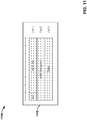
- FIG. 9 illustrates a PDU 902 with another example PDU format 900 that can be implemented via the NCP layer 204.
- the status report can be explicitly transmitted in the NCP layer 204, and the SN could not be explicitly included in the user plane NCP layer PDU 902.
- the PDU 902 is also illustrated in FIG. 6 as status report 602 in a status report control PDU format, which can be with a bit sequence number (e.g., 15 bits or otherwise).
- the format of PDU 902 can comprise a D/C indicator that indicates whether the PDU is a control PDU or a data PDU.
- the control PDU could be indicated as zero, while the data PDU as one, or vice versa.
- the PDU type field can indicate the type of PDU, and can be defined for future extensibility. In this example it can be 000 as fixed.
- the "R" field can be the reserve bits.
- the first missing SN (FMS) can be the NCP layer SN of the first missing NCP SDU.
- the bitmaps can be designated as the most significant bit (MSB) of the first octet (Oct) of the type "Bitmap", which indicates whether or not the NCP SDU with the SN (FMS + 1) modulo (Maximum_NCP_SN +1) has been received correctly.
- the least significant bit (LSB) of the first octet of the type "Bitmap” can indicate whether or not the NCP SDU with the SN (FMS +8) modulo (Maximum_NCP_SN +1) has been received.
- Maximum_NCP_SN 2 N - 1, while N is the sequence number length. For example, a 15 bit sequence number, the Maximum_NCP_SN can be 32,767.
- a status report can also be provided in other methods. For example, an explicit list of NCP SN(s) successfully received by the receiver side or logic component could also be provided.
- FIG. 10 illustrates a PDU 1002 with another example PDU format 1000 that can be implemented via the NCP layer 204.
- a user plane Data PDU can be transmitted without the SN.
- the PDU format is shown with 15 bit sequence number.
- the D/C field indicates whether the PDU is control PDU or data PDU.
- the control PDU can be indicated as 0, while data PDU as 1, or vice versa.
- Field "R" means the reserved bit. It is also possible to define PDU formats with other lengths (e.g. 12 bits) for sequence number and another number of reserved bits.
- FIG. 11 illustrates a PDU 1102 with another example PDU format 1100 that can be implemented via the NCP layer 204.
- NCP SN 15 bit sequence number
- the Data PDU format 1100 can also have a 15 bit sequence number, for example, (as field NCP SN), in which the format can also be similar as the PDU format 800 in FIG. 8 also, except for the field D/C which indicates whether the PDU is a control PDU or a data PDU.
- control PDU can be indicated as 0, while data PDU as 1.
- PDU formats with other lengths (e.g. 12 bits) for sequence number and/or other number of reserved bits.
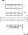
- FIG. 12 illustrates a method 1200 for facilitating network operations in response to a fallback from a block in a heterogeneous network between LTE and 5G nodes.
- the method 1200 for example, and various aspects/embodiments discloses can be implemented on a computer-readable media or medium.
- the media or medium can comprise executable instructions that, in response to execution, cause a network device comprising one or more processors to perform operations in a multi-radio heterogeneous network of a radio access network (RAN), such as with an LTE node or 5G mmW node.
- RAN radio access network
- the method initiates with receiving, by a receive logic component of the network device from a first layer, a first data unit associated with a network convergence protocol (NCP) layer.
- NCP network convergence protocol
- the method can include generating, by the one or more processors, a second data unit associated with the NCP layer based on the first data unit.
- the method can include controlling packet communication, via the NCP layer by the one or more processors, without mapping a bearer in response to a fallback operation from another network device that is communicatively coupled to the NCP layer on the multi-radio heterogeneous network of the RAN.
- the method can include transmitting, by the network device to a second layer, the second data unit associated with the NCP layer.
- the first layer can comprise an upper protocol layer
- the first data unit can comprise a NCP service data unit (SDU)
- the second layer can comprise a lower protocol layer
- the second data unit can comprise a NCP protocol data unit (PDU).
- the first layer can comprise the lower protocol layer
- the first data unit can comprise the NCP PDU
- the second layer can comprise the upper protocol layer
- the second data unit can comprise the NCP SDU.
- the upper protocol layer can be an internet protocol (IP) layer, while the lower protocol layer can be a packet data convergence protocol (PDCP) layer.
- IP internet protocol
- PDCP packet data convergence protocol
- the generating, by the network device, the second data unit can be based on a reordering process, for example.
- the method can include performing a duplicate discard prior to a delivery of the NCP SDU to the upper protocol layer.
- the method can further include transmitting, by the network device in the NCP layer, one or more of a sequence number or a status report, wherein the status report comprises a NCP sequence number of a first missing NCP SDU (FMS) and a bitmap indicating whether SDUs following the FMS have been successfully received.
- FMS first missing NCP SDU
- FIG. 13 illustrates, for one embodiment, example components of a User Equipment (UE) device 1300.
- the UE device 1300 may include application circuitry 1302, baseband circuitry 1304, Radio Frequency (RF) circuitry 1306, front-end module (FEM) circuitry 1308 and one or more antennas 1310, coupled together at least as shown.
- RF Radio Frequency
- FEM front-end module
- the application circuitry 1302 may include one or more application processors.
- the application circuitry 1302 may include circuitry such as, but not limited to, one or more single-core or multi-core processors.
- the processor(s) may include any combination of general-purpose processors and dedicated processors (e.g., graphics processors, application processors, etc.).
- the processors may be coupled with and/or may include memory/storage and may be configured to execute instructions stored in the memory/storage to enable various applications and/or operating systems to run on the system.
- the baseband circuitry 1304 may include circuitry such as, but not limited to, one or more single-core or multi-core processors.
- the baseband circuitry 1304 may include one or more baseband processors and/or control logic to process baseband signals received from a receive signal path of the RF circuitry 1306 and to generate baseband signals for a transmit signal path of the RF circuitry 1306.
- Baseband processing circuity 1304 may interface with the application circuitry 1302 for generation and processing of the baseband signals and for controlling operations of the RF circuitry 1306.
- the baseband circuitry 1304 may include a second generation (2G) baseband processor 1304a, third generation (3G) baseband processor 1304b, fourth generation (4G) baseband processor 1304c, and/or other baseband processor(s) 1304d for other existing generations, generations in development or to be developed in the future (e.g., fifth generation (5G), 6G, etc.).
- the baseband circuitry 1304 e.g., one or more of baseband processors 1304a-d
- the radio control functions may include, but are not limited to, signal modulation/demodulation, encoding/decoding, radio frequency shifting, etc.
- modulation/demodulation circuitry of the baseband circuitry 1304 may include Fast-Fourier Transform (FFT), precoding, and/or constellation mapping/demapping functionality.
- FFT Fast-Fourier Transform
- encoding/decoding circuitry of the baseband circuitry 1304 may include convolution, tail-biting convolution, turbo, Viterbi, and/or Low Density Parity Check (LDPC) encoder/decoder functionality.
- LDPC Low Density Parity Check
- the baseband circuitry 1304 may include elements of a protocol stack such as, for example, elements of an evolved universal terrestrial radio access network (EUTRAN) protocol including, for example, physical (PHY), media access control (MAC), radio link control (RLC), packet data convergence protocol (PDCP), and/or radio resource control (RRC) elements.
- EUTRAN evolved universal terrestrial radio access network
- a central processing unit (CPU) 1304e of the baseband circuitry 1304 may be configured to run elements of the protocol stack for signaling of the PHY, MAC, RLC, PDCP and/or RRC layers.
- the baseband circuitry may include one or more audio digital signal processor(s) (DSP) 1304f.
- DSP audio digital signal processor
- the audio DSP(s) 1304f may be include elements for compression/decompression and echo cancellation and may include other suitable processing elements in other embodiments.
- Components of the baseband circuitry may be suitably combined in a single chip, a single chipset, or disposed on a same circuit board in some embodiments.
- some or all of the constituent components of the baseband circuitry 1304 and the application circuitry 1302 may be implemented together such as, for example, on a system on a chip (SOC).
- SOC system on a chip
- the baseband circuitry 1304 may provide for communication compatible with one or more radio technologies.
- the baseband circuitry 1304 may support communication with an evolved universal terrestrial radio access network (EUTRAN) and/or other wireless metropolitan area networks (WMAN), a wireless local area network (WLAN), a wireless personal area network (WPAN).
- EUTRAN evolved universal terrestrial radio access network
- WMAN wireless metropolitan area networks
- WLAN wireless local area network
- WPAN wireless personal area network
- multi-mode baseband circuitry Embodiments in which the baseband circuitry 1304 is configured to support radio communications of more than one wireless protocol.
- RF circuitry 1306 may enable communication with wireless networks using modulated electromagnetic radiation through a non-solid medium.
- the RF circuitry 1306 may include switches, filters, amplifiers, etc. to facilitate the communication with the wireless network.
- RF circuitry 1306 may include a receive signal path which may include circuitry to down-convert RF signals received from the FEM circuitry 1308 and provide baseband signals to the baseband circuitry 1304.
- RF circuitry 1306 may also include a transmit signal path which may include circuitry to up-convert baseband signals provided by the baseband circuitry 1304 and provide RF output signals to the FEM circuitry 1308 for transmission.
- the RF circuitry 1306 may include a receive signal path and a transmit signal path.
- the receive signal path of the RF circuitry 1306 may include mixer circuitry 1306a, amplifier circuitry 1306b and filter circuitry 1306c.
- the transmit signal path of the RF circuitry 1306 may include filter circuitry 1306c and mixer circuitry 1306a.
- RF circuitry 1306 may also include synthesizer circuitry 1306d for synthesizing a frequency for use by the mixer circuitry 1306a of the receive signal path and the transmit signal path.
- the mixer circuitry 1306a of the receive signal path may be configured to down-convert RF signals received from the FEM circuitry 1308 based on the synthesized frequency provided by synthesizer circuitry 1306d.
- the amplifier circuitry 1306b may be configured to amplify the down-converted signals and the filter circuitry 1306c may be a low-pass filter (LPF) or bandpass filter (BPF) configured to remove unwanted signals from the down-converted signals to generate output baseband signals.
- LPF low-pass filter
- BPF bandpass filter
- Output baseband signals may be provided to the baseband circuitry 1304 for further processing.
- the output baseband signals may be zero-frequency baseband signals, although this is not a requirement.
- mixer circuitry 1306a of the receive signal path may comprise passive mixers, although the scope of the embodiments is not limited in this respect.
- the mixer circuitry 1306a of the transmit signal path may be configured to up-convert input baseband signals based on the synthesized frequency provided by the synthesizer circuitry 1306d to generate RF output signals for the FEM circuitry 1308.
- the baseband signals may be provided by the baseband circuitry 1304 and may be filtered by filter circuitry 1306c.
- the filter circuitry 1306c may include a low-pass filter (LPF), although the scope of the embodiments is not limited in this respect.
- LPF low-pass filter
- the mixer circuitry 1306a of the receive signal path and the mixer circuitry 1306a of the transmit signal path may include two or more mixers and may be arranged for quadrature downconversion and/or upconversion respectively.
- the mixer circuitry 1306a of the receive signal path and the mixer circuitry 1306a of the transmit signal path may include two or more mixers and may be arranged for image rejection (e.g., Hartley image rejection).
- the mixer circuitry 1306a of the receive signal path and the mixer circuitry 1306a may be arranged for direct downconversion and/or direct upconversion, respectively.
- the mixer circuitry 1306a of the receive signal path and the mixer circuitry 1306a of the transmit signal path may be configured for superheterodyne operation.
- the output baseband signals and the input baseband signals may be analog baseband signals, although the scope of the embodiments is not limited in this respect.
- the output baseband signals and the input baseband signals may be digital baseband signals.
- the RF circuitry 1306 may include analog-to-digital converter (ADC) and digital-to-analog converter (DAC) circuitry and the baseband circuitry 1304 may include a digital baseband interface to communicate with the RF circuitry 1306.
- ADC analog-to-digital converter
- DAC digital-to-analog converter
- a separate radio IC circuitry may be provided for processing signals for each spectrum, although the scope of the embodiments is not limited in this respect.
- the synthesizer circuitry 1306d may be a fractional-N synthesizer or a fractional N/N+1 synthesizer, although the scope of the embodiments is not limited in this respect as other types of frequency synthesizers may be suitable.
- synthesizer circuitry 1306d may be a delta-sigma synthesizer, a frequency multiplier, or a synthesizer comprising a phase-locked loop with a frequency divider.
- the synthesizer circuitry 1306d may be configured to synthesize an output frequency for use by the mixer circuitry 1306a of the RF circuitry 1306 based on a frequency input and a divider control input. In some embodiments, the synthesizer circuitry 1306d may be a fractional N/N+1 synthesizer.
- frequency input may be provided by a voltage controlled oscillator (VCO), although that is not a requirement.
- VCO voltage controlled oscillator
- Divider control input may be provided by either the baseband circuitry 1304 or the applications processor 1302 depending on the desired output frequency.
- a divider control input (e.g., N) may be determined from a look-up table based on a channel indicated by the applications processor 1302.
- Synthesizer circuitry 1306d of the RF circuitry 1306 may include a divider, a delay-locked loop (DLL), a multiplexer and a phase accumulator.
- the divider may be a dual modulus divider (DMD) and the phase accumulator may be a digital phase accumulator (DPA).
- the DMD may be configured to divide the input signal by either N or N+1 (e.g., based on a carry out) to provide a fractional division ratio.
- the DLL may include a set of cascaded, tunable, delay elements, a phase detector, a charge pump and a D-type flip-flop.
- the delay elements may be configured to break a VCO period up into Nd equal packets of phase, where Nd is the number of delay elements in the delay line.
- Nd is the number of delay elements in the delay line.
- synthesizer circuitry 1306d may be configured to generate a carrier frequency as the output frequency, while in other embodiments, the output frequency may be a multiple of the carrier frequency (e.g., twice the carrier frequency, four times the carrier frequency) and used in conjunction with quadrature generator and divider circuitry to generate multiple signals at the carrier frequency with multiple different phases with respect to each other.
- the output frequency may be a LO frequency (f LO ).
- the RF circuitry 1306 may include an IQ/polar converter.
- FEM circuitry 1308 may include a receive signal path which may include circuitry configured to operate on RF signals received from one or more antennas 1310, amplify the received signals and provide the amplified versions of the received signals to the RF circuitry 1306 for further processing.
- FEM circuitry 1308 may also include a transmit signal path which may include circuitry configured to amplify signals for transmission provided by the RF circuitry 1306 for transmission by one or more of the one or more antennas 1310.
- the FEM circuitry 1308 may include a TX/RX switch to switch between transmit mode and receive mode operation.
- the FEM circuitry may include a receive signal path and a transmit signal path.
- the receive signal path of the FEM circuitry may include a low-noise amplifier (LNA) to amplify received RF signals and provide the amplified received RF signals as an output (e.g., to the RF circuitry 1306).
- the transmit signal path of the FEM circuitry 1308 may include a power amplifier (PA) to amplify input RF signals (e.g., provided by RF circuitry 1306), and one or more filters to generate RF signals for subsequent transmission (e.g., by one or more of the one or more antennas 1310.
- PA power amplifier
- the UE device 1300 may include additional elements such as, for example, memory/storage, display, camera, sensor, and/or input/output (I/O) interface.
- additional elements such as, for example, memory/storage, display, camera, sensor, and/or input/output (I/O) interface.
- FIG. 14 illustrates a block diagram of an embodiment of access (or user) equipment related to access of a network (e.g., network device, base station, wireless access point, femtocell access point, and so forth) that can enable and/or exploit features or aspects disclosed herein.
- a network e.g., network device, base station, wireless access point, femtocell access point, and so forth
- Access equipment e.g., eNB, network entity, or the like
- UE or software related to access of a network can receive and transmit signal(s) from and to wireless devices, wireless ports, wireless routers, etc. through segments 1402 1 -1402 B (B is a positive integer).
- Segments 1402 1 -1402 B can be internal and/or external to access equipment and/or software related to access of a network, and can be controlled by a monitor component 1404 and an antenna component 1406.
- Monitor component 1404 and antenna component 1406 can couple to communication platform 1408, which can include electronic components and associated circuitry that provide for processing and manipulation of received signal(s) and other signal(s) to be transmitted.
- communication platform 1408 includes a receiver/transmitter 1410 that can convert analog signals to digital signals upon reception of the analog signals, and can convert digital signals to analog signals upon transmission.
- receiver/transmitter 1410 can divide a single data stream into multiple, parallel data streams, or perform the reciprocal operation.
- Coupled to receiver/transmitter 1410 can be a multiplexer/demultiplexer 1412 that can facilitate manipulation of signals in time and frequency space.
- Multiplexer/demultiplexer 1412 can multiplex information (data/traffic and control/signaling) according to various multiplexing schemes such as time division multiplexing, frequency division multiplexing, orthogonal frequency division multiplexing, code division multiplexing, space division multiplexing.
- multiplexer/demultiplexer component 1412 can scramble and spread information (e.g., codes, according to substantially any code known in the art, such as Hadamard-Walsh codes, Baker codes, Kasami codes, polyphase codes, and so forth).
- codes e.g., codes, according to substantially any code known in the art, such as Hadamard-Walsh codes, Baker codes, Kasami codes, polyphase codes, and so forth.
- a modulator/demodulator 1414 is also a part of communication platform 1408, and can modulate information according to multiple modulation techniques, such as frequency modulation, amplitude modulation (e.g., M-ary quadrature amplitude modulation, with M a positive integer); phase-shift keying; and so forth).
- modulation techniques such as frequency modulation, amplitude modulation (e.g., M-ary quadrature amplitude modulation, with M a positive integer); phase-shift keying; and so forth).
- Access equipment and/or software related to access of a network also includes a processor 1416 configured to confer, at least in part, functionality to substantially any electronic component in access equipment and/or software.
- processor 1416 can facilitate configuration of access equipment and/or software through, for example, monitor component 1404, antenna component 1406, and one or more components therein.
- access equipment and/or software can include display interface 1418, which can display functions that control functionality of access equipment and/or software or reveal operation conditions thereof.
- display interface 1418 can include a screen to convey information to an end user.
- display interface 1418 can be a liquid crystal display, a plasma panel, a monolithic thin-film based electrochromic display, and so on.
- display interface 1418 can include a component (e.g., speaker) that facilitates communication of aural indicia, which can also be employed in connection with messages that convey operational instructions to an end user.
- Display interface 1418 can also facilitate data entry (e.g., through a linked keypad or through touch gestures), which can cause access equipment and/or software to receive external commands (e.g., restart operation).
- Broadband network interface 1420 facilitates connection of access equipment and/or software to a service provider network (not shown) that can include one or more cellular technologies (e.g., third generation partnership project universal mobile telecommunication system, global system for mobile communication, and so on) through backhaul link(s) (not shown), which enable incoming and outgoing data flow.
- Broadband network interface 1420 can be internal or external to access equipment and/or software and can utilize display interface 1418 for end-user interaction and status information delivery.
- Processor 1416 can be functionally connected to communication platform 1408 and can facilitate operations on data (e.g., symbols, bits, or chips) for multiplexing/demultiplexing, such as effecting direct and inverse fast Fourier transforms, selection of modulation rates, selection of data packet formats, inter-packet times, and so on. Moreover, processor 1416 can be functionally connected, through data, system, or an address bus 1422, to display interface 1418 and broadband network interface 1420, to confer, at least in part, functionality to each of such components.
- data e.g., symbols, bits, or chips
- processor 1416 can be functionally connected, through data, system, or an address bus 1422, to display interface 1418 and broadband network interface 1420, to confer, at least in part, functionality to each of such components.
- memory 1424 can retain location and/or coverage area (e.g., macro sector, identifier(s)) access list(s) that authorize access to wireless coverage through access equipment and/or software sector intelligence that can include ranking of coverage areas in the wireless environment of access equipment and/or software, radio link quality and strength associated therewith, or the like.
- Memory 1424 also can store data structures, code instructions and program modules, system or device information, code sequences for scrambling, spreading and pilot transmission, access point configuration, and so on.
- Processor 1416 can be coupled (e.g., through a memory bus), to memory 1424 in order to store and retrieve information used to operate and/or confer functionality to the components, platform, and interface that reside within access equipment and/or software.
- FIG. 14 illustrates an electronic device (e.g., access equipment or UE) that can be, or can be incorporated into or otherwise part of, an eNB, a UE, or some other type of electronic device in accordance with various embodiments.
- the electronic device can be logic and/or circuitry that can be at least partially implemented in one or more of hardware, software, and/or firmware.
- the electronic device logic can include radio transmit logic and receive logic (e.g., 1410) coupled to control logic (e.g., 1416).
- the transmit and/or receive logic can be elements or modules of transceiver logic, as shown.
- the electronic device and/or the components of the electronic device can be configured to perform operations similar to those described elsewhere in this disclosure.
- the receive logic can be to receive, from a first layer, a first data unit associated with a Network Convergence Protocol (NCP) layer.
- the control logic can be to process the first data unit to generate a second data unit associated with the NCP layer.
- the transmit logic can be to transmit the second data unit to a second layer.
- NCP Network Convergence Protocol
- the electronic device can be configured to perform one or more processes or methods as described herein.
- the process can include receiving, by an electronic device from a first layer, a first data unit associated with a Network Convergence Protocol (NCP) layer.
- the process can further include transmitting, by the electronic device to a second layer, a second data unit associated with the NCP layer, wherein the second data unit is based on the first data unit
- NCP Network Convergence Protocol
- processor can refer to substantially any computing processing unit or device including, but not limited to including, single-core processors; single-processors with software multithread execution capability; multi-core processors; multi-core processors with software multithread execution capability; multi-core processors with hardware multithread technology; parallel platforms; and parallel platforms with distributed shared memory.
- a processor can refer to an integrated circuit, an application specific integrated circuit, a digital signal processor, a field programmable gate array, a programmable logic controller, a complex programmable logic device, a discrete gate or transistor logic, discrete hardware components, or any combination thereof designed to perform the functions and/or processes described herein.
- processors can exploit nano-scale architectures such as, but not limited to, molecular and quantum-dot based transistors, switches and gates, in order to optimize space usage or enhance performance of mobile devices.
- a processor may also be implemented as a combination of computing processing units.
- nonvolatile memory for example, can be included in a memory, non-volatile memory (see below), disk storage (see below), and memory storage (see below). Further, nonvolatile memory can be included in read only memory, programmable read only memory, electrically programmable read only memory, electrically erasable programmable read only memory, or flash memory. Volatile memory can include random access memory, which acts as external cache memory. By way of illustration and not limitation, random access memory is available in many forms such as synchronous random access memory, dynamic random access memory, synchronous dynamic random access memory, double data rate synchronous dynamic random access memory, enhanced synchronous dynamic random access memory, Synchlink dynamic random access memory, and direct Rambus random access memory. Additionally, the disclosed memory components of systems or methods herein are intended to include, without being limited to including, these and any other suitable types of memory.
- Examples can include subject matter such as a method, means for performing acts or blocks of the method, at least one machine-readable medium including instructions that, when performed by a machine cause the machine to perform acts of the method or of an apparatus or system for concurrent communication using multiple communication technologies according to embodiments and examples described herein.
- Computer-readable media includes both computer storage media and communication media including any medium that facilitates transfer of a computer program from one place to another.
- a storage media or a computer readable storage device can be any available media that can be accessed by a general purpose or special purpose computer.
- such computer-readable media can comprise RAM, ROM, EEPROM, CD-ROM or other optical disk storage, magnetic disk storage or other magnetic storage devices, or other tangible and/or non-transitory medium, that can be used to carry or store desired information or executable instructions.
- any connection is properly termed a computer-readable medium.
- a computer-readable medium includes compact disc (CD), laser disc, optical disc, digital versatile disc (DVD), floppy disk and blu-ray disc where disks usually reproduce data magnetically, while discs reproduce data optically with lasers. Combinations of the above should also be included within the scope of computer-readable media.
- DSP digital signal processor
- ASIC application specific integrated circuit
- FPGA field programmable gate array
- a general-purpose processor can be a microprocessor, but, in the alternative, processor can be any conventional processor, controller, microcontroller, or state machine.
- a processor can also be implemented as a combination of computing devices, for example, a combination of a DSP and a microprocessor, a plurality of microprocessors, one or more microprocessors in conjunction with a DSP core, or any other such configuration. Additionally, at least one processor can comprise one or more modules operable to perform one or more of the s and/or actions described herein.
- modules e.g., procedures, functions, and so on
- Software codes can be stored in memory units and executed by processors.
- Memory unit can be implemented within processor or external to processor, in which case memory unit can be communicatively coupled to processor through various means as is known in the art.
- at least one processor can include one or more modules operable to perform functions described herein.
- a CDMA system can implement a radio technology such as Universal Terrestrial Radio Access (UTRA), CDMA1800, etc.
- UTRA includes Wideband-CDMA (W-CDMA) and other variants of CDMA.
- W-CDMA Wideband-CDMA
- CDMA1800 covers IS-1800, IS-95 and IS-856 standards.
- a TDMA system can implement a radio technology such as Global System for Mobile Communications (GSM).
- GSM Global System for Mobile Communications
- An OFDMA system can implement a radio technology such as Evolved UTRA (E-UTRA), Ultra Mobile Broadband (UMB), IEEE 802.11 (Wi-Fi), IEEE 802.16 (WiMAX), IEEE 802.18, Flash-OFDML, etc.
- E-UTRA Evolved UTRA
- UMB Ultra Mobile Broadband
- IEEE 802.11 Wi-Fi
- WiMAX IEEE 802.16
- IEEE 802.18, Flash-OFDML etc.
- UTRA and E-UTRA are part of Universal Mobile Telecommunication System (UMTS).
- UMTS Universal Mobile Telecommunication System
- 3GPP Long Term Evolution (LTE) is a release of UMTS that uses E-UTRA, which employs OFDMA on downlink and SC-FDMA on uplink.
- UTRA, E-UTRA, UMTS, LTE and GSM are described in documents from an organization named "3rd Generation Partnership Project" (3GPP).
- CDMA1800 and UMB are described in documents from an organization named "3rd Generation Partnership Project 2" (3GPP2).
- 3GPP2 3rd Generation Partnership Project 2
- such wireless communication systems can additionally include peer-to-peer (e.g., mobile-to-mobile) ad hoc network systems often using unpaired unlicensed spectrums, 802.xx wireless LAN, BLUETOOTH and any other short- or long- range, wireless communication techniques.
- SC-FDMA Single carrier frequency division multiple access
- SC-FDMA Single carrier frequency division multiple access
- SC-FDMA has similar performance and essentially a similar overall complexity as those of OFDMA system.
- SC-FDMA signal has lower peak-to-average power ratio (PAPR) because of its inherent single carrier structure.
- PAPR peak-to-average power ratio
- SC-FDMA can be utilized in uplink communications where lower PAPR can benefit a mobile terminal in terms of transmit power efficiency.
- various aspects or features described herein can be implemented as a method, apparatus, or article of manufacture using standard programming and/or engineering techniques.
- article of manufacture as used herein is intended to encompass a computer program accessible from any computer-readable device, carrier, or media.
- computer-readable media can include but are not limited to magnetic storage devices (e.g., hard disk, floppy disk, magnetic strips, etc. ), optical disks (e.g., compact disk (CD), digital versatile disk (DVD), etc. ), smart cards, and flash memory devices (e.g., EPROM, card, stick, key drive, etc. ).
- various storage media described herein can represent one or more devices and/or other machine-readable media for storing information.
- machine-readable medium can include, without being limited to, wireless channels and various other media capable of storing, containing, and/or carrying instruction(s) and/or data.
- a computer program product can include a computer readable medium having one or more instructions or codes operable to cause a computer to perform functions described herein.
- Communications media embody computer-readable instructions, data structures, program modules or other structured or unstructured data in a data signal such as a modulated data signal, e.g., a carrier wave or other transport mechanism, and includes any information delivery or transport media.
- modulated data signal or signals refers to a signal that has one or more of its characteristics set or changed in such a manner as to encode information in one or more signals.
- communication media include wired media, such as a wired network or direct-wired connection, and wireless media such as acoustic, RF, infrared and other wireless media.
- a software module can reside in RAM memory, flash memory, ROM memory, EPROM memory, EEPROM memory, registers, a hard disk, a removable disk, a CD-ROM, or any other form of storage medium known in the art.
- An exemplary storage medium can be coupled to processor, such that processor can read information from, and write information to, storage medium.
- storage medium can be integral to processor.
- processor and storage medium can reside in an ASIC.
- ASIC can reside in a user terminal.
- processor and storage medium can reside as discrete components in a user terminal.
- the s and/or actions of a method or algorithm can reside as one or any combination or set of codes and/or instructions on a machine-readable medium and/or computer readable medium, which can be incorporated into a computer program product.
Landscapes
- Engineering & Computer Science (AREA)
- Computer Networks & Wireless Communication (AREA)
- Signal Processing (AREA)
- Computer Security & Cryptography (AREA)
- Mobile Radio Communication Systems (AREA)
Claims (14)
- Procédé, réalisé par un appareil au sein d'un équipement utilisateur, noté UE, destiné à permettre audit UE de communiquer avec un réseau d'accès radio, noté RAN, ledit appareil mettant en œuvre une couche en protocole de convergence réseau, noté NCP, qui est couplée en communication à deux piles de protocoles radio de l'UE, lesdites piles de protocoles radio comprenant une première pile de protocoles radio pour la communication entre ledit UE et un premier nœud du RAN au moyen d'une première technologie d'accès radio, notée RAT, et une deuxième pile de protocoles radio pour la communication entre ledit UE et un deuxième nœud du RAN au moyen d'une deuxième RAT, chacune desdites première et deuxième piles de protocoles radio comprenant une couche en PDCP, ladite première RAT consistant en une RAT sur ondes millimétriques 5G, ladite deuxième RAT consistant soit en ladite RAT sur ondes millimétriques 5G, soit en une RAT de type LTE, ledit procédé comprenant la réalisation des étapes suivantes :la réception, en provenance d'une couche en IP au-dessus de la couche en NCP, d'une SDU en NCP sur voie montante pour sa livraison au RAN ; etla génération d'une PDU en NCP sur voie montante à la suite du traitement de ladite SDU en NCP sur voie montante ; etla fourniture de la PDU en NCP sur voie montante à la couche en PDCP de la première pile de protocoles radio pour sa livraison au RAN par le biais de la première pile de protocoles radio ; etla détermination, en réponse à cela, si la SDU en NCP sur voie montante a été livrée avec succès ou non au RAN ; etsi la SDU en NCP sur voie montante n'a pas été livrée avec succès au RAN, la retransmission de ladite SDU en NCP sur voie montante par fourniture de ladite PDU en NCP sur voie montante à la couche en PDCP de la deuxième pile de protocoles radio pour sa livraison au RAN par le biais de la deuxième pile de protocoles radio.
- Procédé selon la revendication 1, comprenant en outre, en réponse à la détermination que l'UE a réalisé une opération de repli du premier nœud du RAN vers le deuxième nœud de RAN, les étapes suivantes :la réception d'une PDU en NCP sur voie descendante en provenance de la couche en PDCP de la deuxième pile de protocoles radio ; etla génération d'une SDU en NCP sur voie descendante à la suite du traitement de ladite PDU en NCP sur voie descendante ; etsi ladite SDU en NCP sur voie descendante est hors séquence, la réalisation d'un processus de remise en ordre avant une livraison de la SDU en NCP sur voie descendante à la couche en IP ; etsi ladite SDU en NCP sur voie descendante est en doublon, le rejet de ladite SDU en NCP sur voie descendante doublon avant la livraison de la SDU de couche en NCP sur voie descendante à la couche en IP.
- Procédé selon la revendication 2, comprenant en outre :
la génération d'un rapport d'état sous forme d'une PDU en NCP sur voie montante, le rapport d'état comprenant au moins un numéro de séquence en NCP d'une première SDU manquante, notée FMS, d'une pluralité de SDU en NCP sur voie descendante. - Procédé selon la revendication 3, dans lequel le rapport d'état comporte également un bitmap indiquant si des SDU en NCP sur voie descendante qui suivent les FMS sont reçues avec succès ou non.
- Procédé selon l'une quelconque des revendications 1 à 4, dans lequel chaque PDU en NCP comprend un champ d'un en-tête en NCP indiquant si la PDU en NCP est une PDU en NCP de commande ou une PDU en NCP de données.
- Procédé selon l'une quelconque des revendications 1 à 5, dans lequel l'étape de détermination que l'UE a réalisé une opération de repli du premier nœud du RAN vers le deuxième nœud du RAN comprend la détection d'une situation d'obstruction entre le premier nœud du RAN et l'UE.
- Procédé, réalisé par un appareil au sein d'un nœud d'un réseau d'accès radio, noté RAN, destiné à permettre audit RAN de communiquer avec un équipement utilisateur, ledit appareil mettant en œuvre une couche en protocole de convergence réseau, noté NCP, qui est couplée en communication à deux piles de protocoles radio, lesdites piles de protocoles radio comprenant une première pile de protocoles radio au sein d'un premier nœud du RAN et une deuxième pile de protocoles radio avec un deuxième nœud du RAN, la première pile de protocoles permettant la communication entre ledit UE et ledit premier nœud du RAN au moyen d'une première technologie d'accès radio, notée RAT, et la deuxième pile de protocoles radio permettant la communication entre ledit UE et ledit deuxième nœud du RAN au moyen d'une deuxième RAT, chacune des première et deuxième piles de protocoles radio comprenant une couche en PDCP, ladite première RAT consistant en une RAT sur ondes millimétriques 5G, ladite deuxième RAT consistant soit en ladite RAT sur ondes millimétriques 5G, soit en une RAT de type LTE, ledit procédé comprenant :la réception, en provenance d'une couche en IP au-dessus de la couche en NCP, d'une SDU en NCP sur voie descendante pour sa livraison à l'UE ; etla génération d'une PDU en NCP sur voie descendante à la suite du traitement de ladite SDU en NCP sur voie descendante ; etla transmission de la PDU en NCP sur voie descendante à la couche en PDCP de la première pile de protocoles radio pour sa livraison à l'UE par le biais de la première pile de protocoles radio ; etla détermination que l'UE a réalisé un repli du premier nœud du RAN vers le deuxième nœud du RAN ;la détermination, en réponse à cela, si la SDU en NCP sur voie descendante a été livrée avec succès ou non à l'UE ; etsi la SDU en NCP sur voie descendante n'a pas été livrée avec succès à l'UE, la retransmission de ladite SDU en NCP sur voie descendante par fourniture de ladite PDU en NCP sur voie descendante à la couche en PDCP de la deuxième pile de protocoles radio pour sa livraison à l'UE par le biais de la deuxième pile de protocoles radio.
- Procédé selon la revendication 7, comprenant en outre, en réponse à la détermination que l'UE a réalisé une opération de repli du premier nœud du RAN vers le deuxième nœud du RAN, les étapes suivantes :la réception d'une PDU en NCP sur voie montante en provenance de la couche en PDCP de la deuxième pile de protocoles radio ; etla génération d'une SDU en NCP sur voie montante à la suite du traitement de ladite PDU en NCP sur voie montante ; etsi ladite SDU en NCP sur voie montante est hors séquence, la réalisation d'un processus de remise en ordre avant une livraison de la SDU en NCP sur voie montante à la couche en IP ; etsi ladite SDU en NCP sur voie montante est en doublon, le rejet de ladite SDU en NCP sur voie montante doublon avant la livraison de la SDU de couche en NCP sur voie montante à la couche en IP.
- Procédé selon l'une quelconque des revendications 7 à 8, dans lequel l'étape de détermination que l'UE a réalisé une opération de repli du premier nœud du RAN vers le deuxième nœud du RAN comprend la détection d'une situation d'obstruction entre le premier RAN et l'UE.
- Procédé selon l'une quelconque des revendications 7 à 9, comprenant en outre la transmission d'un numéro de séquence et d'un rapport d'état indiquant une ou plusieurs SDU en NCP sur voie montante qui ont été reçues avec succès parmi une pluralité de SDU en NCP.
- Appareil au sein d'un équipement utilisateur, noté UE, ledit appareil comprenant :une mémoire adaptée à enregistrer des composants exécutables par ordinateur ; etune circuiterie de traitement, couplée en communication à la mémoire, adaptée à exécuter les composants exécutables par ordinateur, les composants exécutables par ordinateur étant adaptés à réaliser le procédé selon l'une quelconque des revendications 1 à 6.
- Appareil au sein d'un nœud d'un réseau d'accès radio, ledit appareil comprenant :une mémoire adaptée à enregistrer des composants exécutables par ordinateur ; etune circuiterie de traitement, couplée en communication à la mémoire, adaptée à exécuter les composants exécutables par ordinateur, les composants exécutables par ordinateur étant adaptés à réaliser le procédé selon l'une quelconque des revendications 7 à 10.
- Support lisible par ordinateur comprenant des instructions exécutables qui, en réponse à leur exécution par un appareil au sein d'un équipement utilisateur, noté UE, amènent ledit appareil à réaliser le procédé selon l'une quelconque des revendications 1 à 6.
- Support lisible par ordinateur comprenant des instructions exécutables qui, en réponse à leur exécution par un appareil au sein d'un nœud d'un réseau d'accès radio, amènent ledit appareil à réaliser le procédé selon l'une quelconque des revendications 7 à 10.
Applications Claiming Priority (2)
| Application Number | Priority Date | Filing Date | Title |
|---|---|---|---|
| US201562195620P | 2015-07-22 | 2015-07-22 | |
| PCT/US2015/067077 WO2017014802A1 (fr) | 2015-07-22 | 2015-12-21 | Couche de convergence pour systèmes de communication 5g |
Publications (2)
| Publication Number | Publication Date |
|---|---|
| EP3326408A1 EP3326408A1 (fr) | 2018-05-30 |
| EP3326408B1 true EP3326408B1 (fr) | 2020-04-01 |
Family
ID=55085941
Family Applications (1)
| Application Number | Title | Priority Date | Filing Date |
|---|---|---|---|
| EP15823476.5A Active EP3326408B1 (fr) | 2015-07-22 | 2015-12-21 | Couche de convergence pour systèmes de communication 5g |
Country Status (3)
| Country | Link |
|---|---|
| US (1) | US11233725B2 (fr) |
| EP (1) | EP3326408B1 (fr) |
| WO (1) | WO2017014802A1 (fr) |
Families Citing this family (29)
| Publication number | Priority date | Publication date | Assignee | Title |
|---|---|---|---|---|
| WO2016122589A1 (fr) * | 2015-01-30 | 2016-08-04 | Nokia Solutions And Networks Oy | Amélioration de transferts entre différents réseaux d'accès |
| US11265956B2 (en) * | 2016-05-12 | 2022-03-01 | Ntt Docomo, Inc. | Radio communication system and user device |
| CN108307537B (zh) * | 2016-09-28 | 2020-07-14 | 华为技术有限公司 | 一种报文交互方法及相关设备 |
| US10880871B2 (en) * | 2016-11-01 | 2020-12-29 | Sharp Kabushiki Kaisha | Method and apparatus for asymmetrical up-link/down-link protocol stack and frame structure in a 5G NR communication system |
| EP3535877A1 (fr) * | 2016-11-04 | 2019-09-11 | Telefonaktiebolaget LM Ericsson (publ) | Activation de traitement efficace de copies de paquets redondantes dans un système de communication sans fil |
| WO2018084760A1 (fr) | 2016-11-04 | 2018-05-11 | Telefonaktiebolaget Lm Ericsson (Publ) | Activation et désactivation de transmission de duplication |
| US10749639B2 (en) * | 2017-01-24 | 2020-08-18 | Mediatek Inc. | Bearer switching in reduced radio link quality conditions |
| US10716094B2 (en) * | 2017-03-23 | 2020-07-14 | Ofinno, Llc | Packet duplication in a wireless device and wireless network |
| TWI702881B (zh) * | 2017-06-16 | 2020-08-21 | 新加坡商聯發科技(新加坡)私人有限公司 | 行動通信中處理資料重複之方法和裝置 |
| US11483891B2 (en) | 2017-08-11 | 2022-10-25 | Samsung Electronics Co., Ltd. | Method for performing bearer type change of a plurality of bearers configured for user equipment |
| WO2019031947A1 (fr) | 2017-08-11 | 2019-02-14 | Samsung Electronics Co., Ltd. | Procédé et système pour réaliser un transfert dans un réseau de communication sans fil |
| US20190075438A1 (en) * | 2017-09-01 | 2019-03-07 | Idac Holdings, Inc. | Methods and apparatuses for enabling physical layer sharing among multiple wireless communication entities |
| CN117979466A (zh) | 2017-09-29 | 2024-05-03 | 三星电子株式会社 | 在无线通信系统中以双连接处理用户平面的方法和用户设备 |
| US11196517B2 (en) | 2017-10-07 | 2021-12-07 | Lg Electronics Inc. | Method and apparatus for controlling packet duplication |
| KR102381036B1 (ko) | 2017-11-09 | 2022-03-31 | 삼성전자주식회사 | 무선 통신 시스템에서 데이터 패킷을 처리하기 위한 장치 및 방법 |
| MX2020007460A (es) * | 2018-01-11 | 2020-09-14 | Guangdong Oppo Mobile Telecommunications Corp Ltd | Metodo de procesamiento basado en servicio, dispositivo terminal y dispositivo de red. |
| CN111602444B (zh) | 2018-01-12 | 2024-02-02 | 瑞典爱立信有限公司 | 调度请求资源配置 |
| US11201827B2 (en) * | 2018-03-30 | 2021-12-14 | Lg Electronics Inc. | Method and apparatus for performing retransmission after discarding procedure in wireless communication system |
| US11438821B2 (en) * | 2018-10-26 | 2022-09-06 | Samsung Electronics Co., Ltd | Method and system for handling beam blockage in wireless communication system |
| US11082892B2 (en) * | 2018-10-30 | 2021-08-03 | Apple Inc. | Methods for transmitting and receiving data in 5G NR device based on data/service tagging from application processor |
| US11864171B2 (en) * | 2019-03-20 | 2024-01-02 | Ipcom Gmbh & Co. Kg | Coordination of logical channel priorities |
| CN112118192B (zh) * | 2019-06-20 | 2022-11-18 | 华为技术有限公司 | 一种数据量整形方法、网络设备以及计算机程序产品 |
| US11570679B2 (en) * | 2019-07-03 | 2023-01-31 | Mediatek Inc. | Modem and application interaction for voice calls |
| US10841844B1 (en) * | 2019-08-14 | 2020-11-17 | Dish Wireless L.L.C. | Anchor point movement in a compound cellular network |
| US11330665B2 (en) | 2020-01-09 | 2022-05-10 | Qualcomm Incorporated | Increasing throughput efficiency in a PDCP channel with ROHC TCP profile |
| US11451671B2 (en) * | 2020-04-29 | 2022-09-20 | EXFO Solutions SAS | Identification of 5G Non-Standalone Architecture traffic on the S1 interface |
| US11589264B2 (en) * | 2020-07-31 | 2023-02-21 | Charter Communications Operating, Llc | System and method for leveraging access customer premise equipment (CPE) gateway resources to provide 5G edge computing services |
| US11564063B2 (en) | 2020-11-11 | 2023-01-24 | International Business Machines Corporation | Intelligent dynamic communication handoff for mobile applications |
| WO2023003543A1 (fr) * | 2021-07-20 | 2023-01-26 | Zeku, Inc. | Appareil et procédé de traitement de couche 2 hybride parallèle/en pipeline à puissance optimisée pour des paquets de différents types de débit |
Family Cites Families (37)
| Publication number | Priority date | Publication date | Assignee | Title |
|---|---|---|---|---|
| AU776277B2 (en) * | 2000-01-27 | 2004-09-02 | Thomson Licensing S.A. | Method for isochronous resource management in a network based on Hiperlan 2 technology |
| JP2003522507A (ja) * | 2000-02-14 | 2003-07-22 | トムソン ライセンシング ソシエテ アノニム | 幾つかのパケットに分割されるメッセージの送信方法 |
| ES2246325T3 (es) * | 2000-05-15 | 2006-02-16 | Thomson Licensing | Metodo para reservar recursos isocronos en una red inalambrica. |
| JP4751561B2 (ja) * | 2000-05-15 | 2011-08-17 | トムソン ライセンシング | 無線ネットワークを通した等時性データの伝送方法 |
| ATE349840T1 (de) * | 2004-01-30 | 2007-01-15 | Mitsubishi Electric Corp | Verfahren und vorrichtung zur dynamischen ressourcenzuweisung in einem drahtlosen netz |
| EP1909521A1 (fr) * | 2006-10-02 | 2008-04-09 | Matsushita Electric Industrial Co., Ltd. | Méthode de support de qualité de service pendant la durée d'une connexion |
| US8400982B2 (en) * | 2007-09-20 | 2013-03-19 | Lg Electronics Inc. | Method for handling correctly received but header compression failed packets |
| ES2463095T3 (es) * | 2008-02-04 | 2014-05-27 | Lg Electronics Inc. | Método de comunicación inalámbrica para transmitir una secuencia de unidades de datos entre un dispositivo inalámbrico y una red |
| US8553721B2 (en) * | 2008-08-22 | 2013-10-08 | Lantiq Deutschland Gmbh | Channel bonding and packet fragment retransmission method and apparatus |
| WO2010078255A1 (fr) * | 2008-12-29 | 2010-07-08 | Interdigital Patent Holdings, Inc. | Procédé et appareil pour une procédure de mise à jour de zone de suivi et représentation de contextes de porteuses eps |
| WO2010123227A2 (fr) * | 2009-04-21 | 2010-10-28 | Lg Electronics Inc. | Procédé pour faciliter le transfert d'un équipement utilisateur dans un système de communication de paquets de données |
| CN101610587B (zh) * | 2009-07-13 | 2011-12-07 | 中兴通讯股份有限公司 | 一种基于tdd制式的数据传输方法和装置 |
| KR101800289B1 (ko) * | 2010-06-22 | 2017-11-23 | 삼성전자주식회사 | 이동 통신 시스템에서 mdt 측정 정보 보고 방법 및 장치 |
| CN103636257B (zh) * | 2011-07-01 | 2018-07-31 | 交互数字专利控股公司 | 用于支持本地ip接入lipa移动性的方法和装置 |
| KR102362590B1 (ko) * | 2011-07-12 | 2022-02-15 | 인터디지탈 패튼 홀딩스, 인크 | 다중 rat 액세스 모드 동작을 위한 방법 및 장치 |
| US9014247B2 (en) * | 2011-10-14 | 2015-04-21 | Texas Instruments Incorporated | Communication on a pilot wire |
| CN104641682B (zh) * | 2011-10-28 | 2019-01-15 | 黑莓有限公司 | 在电路交换回退操作期间处理承载的方法和装置 |
| JP6001886B2 (ja) * | 2012-03-13 | 2016-10-05 | 株式会社Nttドコモ | 移動局及び無線基地局 |
| WO2013151334A1 (fr) * | 2012-04-03 | 2013-10-10 | 엘지전자 주식회사 | Procédé et dispositif de transfert de service à commutation de paquets dans un système de communication sans fil |
| US10560882B2 (en) * | 2012-06-08 | 2020-02-11 | Blackberry Limited | Method and apparatus for multi-rat transmission |
| DE112013003044T5 (de) * | 2012-08-06 | 2015-03-05 | Lg Electronics Inc. | Ein Verfahren zum Übertragen eines Statusberichts und eine Kommunikationsvorrichtung damit in einem drahtlosen Kommunikationssystem |
| US9072027B2 (en) | 2012-12-07 | 2015-06-30 | Alcatel Lucent | Methods and apparatuses for facilitating D2D bearer switching |
| US9059876B2 (en) * | 2013-01-16 | 2015-06-16 | Broadcom Corporation | Communication system having cross polarization interference cancellation (XPIC) |
| US9973986B2 (en) * | 2013-01-17 | 2018-05-15 | Intel IP Corporation | Systems and methods for mobility optimization in a heterogeneous network |
| US9622134B2 (en) * | 2013-05-06 | 2017-04-11 | Qualcomm Incorporated | Coordinating handover events across RATs |
| US9648514B2 (en) * | 2013-08-09 | 2017-05-09 | Blackberry Limited | Method and system for protocol layer enhancements in data offload over small cells |
| EP2835925B1 (fr) | 2013-08-09 | 2018-08-08 | Panasonic Intellectual Property Corporation of America | Rapport d'état efficace pour des UE dans une connectivité double en mode mobile |
| US20150043492A1 (en) | 2013-08-12 | 2015-02-12 | Electronics And Telecommunications Research Institute | Method for providing dual connectivity in wireless communication system |
| WO2015030845A1 (fr) * | 2013-08-30 | 2015-03-05 | Intel IP Corporation | Déclencheurs de mesure d'assistance à la clientèle dans un réseau sans fil |
| US20150109997A1 (en) * | 2013-10-21 | 2015-04-23 | Alexander Sirotkin | Apparatus, system and method of interfacing between a cellular manager and a wlan access device |
| US9661657B2 (en) * | 2013-11-27 | 2017-05-23 | Intel Corporation | TCP traffic adaptation in wireless systems |
| WO2015115854A1 (fr) * | 2014-01-29 | 2015-08-06 | Samsung Electronics Co., Ltd. | Procédé et appareil de transmission/réception de données au moyen d'une pluralité de porteuses dans un système de communications mobiles |
| KR102235637B1 (ko) * | 2014-01-29 | 2021-04-05 | 삼성전자주식회사 | 무선 통신 시스템에서 D2D(Device to Device) 통신의 자원 할당을 통한 송신/수신 단말의 동작 방법 및 장치 |
| KR102190444B1 (ko) * | 2014-02-21 | 2020-12-11 | 삼성전자주식회사 | 무선 통신 시스템에서 데이터 처리 시스템 및 방법 |
| EP3130117B1 (fr) * | 2014-04-10 | 2019-08-21 | Honeywell International Inc. | Systèmes et procédés de gestion de la couche de protocole de transport dynamique pour système avionique |
| WO2016126238A1 (fr) * | 2015-02-03 | 2016-08-11 | Nokia Solutions And Networks Oy | Améliorations de la connectivité double pour différents réseaux d'accès |
| US10708920B2 (en) * | 2015-03-03 | 2020-07-07 | Qualcomm Incorporated | Method and apparatus for dynamic device capability signaling in wireless communications |
-
2015
- 2015-12-21 EP EP15823476.5A patent/EP3326408B1/fr active Active
- 2015-12-21 WO PCT/US2015/067077 patent/WO2017014802A1/fr active Application Filing
- 2015-12-21 US US15/745,890 patent/US11233725B2/en active Active
Non-Patent Citations (1)
| Title |
|---|
| None * |
Also Published As
| Publication number | Publication date |
|---|---|
| US20180227219A1 (en) | 2018-08-09 |
| EP3326408A1 (fr) | 2018-05-30 |
| US11233725B2 (en) | 2022-01-25 |
| WO2017014802A1 (fr) | 2017-01-26 |
Similar Documents
| Publication | Publication Date | Title |
|---|---|---|
| EP3326408B1 (fr) | Couche de convergence pour systèmes de communication 5g | |
| US10257753B2 (en) | WLAN mobility for LTE/WLAN aggregation | |
| EP3298820B1 (fr) | Indication d'un état pdcp pour déchargement multi-rat | |
| US11758615B2 (en) | User equipment (UE), evolved node-B (ENB) and methods for a packet convergence and link control (PCLC) layer | |
| US11019500B2 (en) | Apparatus for determining an estimated number of bytes to send over a link | |
| US20190037448A1 (en) | Solution for vehicle-to-everything (v2x) communication authorization in 5g system | |
| US20180206282A1 (en) | Bearer splitting | |
| CN111183674A (zh) | 用于流控制触发和反馈的设备和方法 | |
| EP3577941B1 (fr) | Protocole de service de données fiable pour dispositifs ciot | |
| US11122643B2 (en) | LWIP enhancements for reliable DRB switching | |
| WO2018063435A2 (fr) | Protocole pdcp, traitement de commande de liaison radio dans un support réparti à double connectivité | |
| WO2017189034A1 (fr) | Systèmes, procédés et dispositifs pour l'amélioration d'informations de commande de liaison montante | |
| EP3453131B1 (fr) | Équipement d'utilisateur (ue) et procédés de réception de paquets sur un support radio divisé | |
| EP3338387B1 (fr) | Protocole de convergence de données en paquets pour agrégation de réseau local cellulaire/sans fil | |
| WO2017171904A1 (fr) | Dispositif et procédé pour une gestion de cycle de vie de nfv à l'aide de fonctions de gestion de configuration | |
| WO2018102098A1 (fr) | Systèmes, procédés et dispositifs de gestion d'état de tampon de harq | |
| WO2018026393A1 (fr) | Équipement utilisateur (ue), nœud b évolué (enb) et procédés de communication voix sur lte (volte) selon une compression robuste des en-têtes (rohc) | |
| WO2017135986A1 (fr) | Transmission de support multiple dans la liaison montante pour une intégration d'évolution à long terme et wifi | |
| EP3459310B1 (fr) | Stratégies de planification optimisées pour double connectivité et groupement de liaison |
Legal Events
| Date | Code | Title | Description |
|---|---|---|---|
| STAA | Information on the status of an ep patent application or granted ep patent |
Free format text: STATUS: THE INTERNATIONAL PUBLICATION HAS BEEN MADE |
|
| PUAI | Public reference made under article 153(3) epc to a published international application that has entered the european phase |
Free format text: ORIGINAL CODE: 0009012 |
|
| STAA | Information on the status of an ep patent application or granted ep patent |
Free format text: STATUS: REQUEST FOR EXAMINATION WAS MADE |
|
| 17P | Request for examination filed |
Effective date: 20180102 |
|
| AK | Designated contracting states |
Kind code of ref document: A1 Designated state(s): AL AT BE BG CH CY CZ DE DK EE ES FI FR GB GR HR HU IE IS IT LI LT LU LV MC MK MT NL NO PL PT RO RS SE SI SK SM TR |
|
| AX | Request for extension of the european patent |
Extension state: BA ME |
|
| RIN1 | Information on inventor provided before grant (corrected) |
Inventor name: PHUYAL, UMESH Inventor name: FONG, MO-HAN Inventor name: ZHANG, YUJIAN Inventor name: GUY, WEY-YI W. Inventor name: HEO, YOUN HYOUNG Inventor name: YIU, CANDY |
|
| DAV | Request for validation of the european patent (deleted) | ||
| DAX | Request for extension of the european patent (deleted) | ||
| STAA | Information on the status of an ep patent application or granted ep patent |
Free format text: STATUS: EXAMINATION IS IN PROGRESS |
|
| 17Q | First examination report despatched |
Effective date: 20190614 |
|
| REG | Reference to a national code |
Ref country code: DE Ref legal event code: R079 Ref document number: 602015049989 Country of ref document: DE Free format text: PREVIOUS MAIN CLASS: H04W0028020000 Ipc: H04W0028080000 |
|
| GRAP | Despatch of communication of intention to grant a patent |
Free format text: ORIGINAL CODE: EPIDOSNIGR1 |
|
| STAA | Information on the status of an ep patent application or granted ep patent |
Free format text: STATUS: GRANT OF PATENT IS INTENDED |
|
| RIC1 | Information provided on ipc code assigned before grant |
Ipc: H04W 28/02 20090101ALI20190912BHEP Ipc: H04L 12/801 20130101ALI20190912BHEP Ipc: H04L 12/707 20130101ALI20190912BHEP Ipc: H04W 80/02 20090101ALI20190912BHEP Ipc: H04W 36/00 20090101ALN20190912BHEP Ipc: H04W 88/06 20090101ALI20190912BHEP Ipc: H04W 28/08 20090101AFI20190912BHEP |
|
| INTG | Intention to grant announced |
Effective date: 20191010 |
|
| RIN1 | Information on inventor provided before grant (corrected) |
Inventor name: GUY, WEY-YI W. Inventor name: FONG, MO-HAN Inventor name: PHUYAL, UMESH Inventor name: HEO, YOUN HYOUNG Inventor name: ZHANG, YUJIAN Inventor name: YIU, CANDY |
|
| GRAS | Grant fee paid |
Free format text: ORIGINAL CODE: EPIDOSNIGR3 |
|
| GRAA | (expected) grant |
Free format text: ORIGINAL CODE: 0009210 |
|
| STAA | Information on the status of an ep patent application or granted ep patent |
Free format text: STATUS: THE PATENT HAS BEEN GRANTED |
|
| AK | Designated contracting states |
Kind code of ref document: B1 Designated state(s): AL AT BE BG CH CY CZ DE DK EE ES FI FR GB GR HR HU IE IS IT LI LT LU LV MC MK MT NL NO PL PT RO RS SE SI SK SM TR |
|
| REG | Reference to a national code |
Ref country code: GB Ref legal event code: FG4D |
|
| REG | Reference to a national code |
Ref country code: AT Ref legal event code: REF Ref document number: 1252972 Country of ref document: AT Kind code of ref document: T Effective date: 20200415 Ref country code: CH Ref legal event code: EP |
|
| REG | Reference to a national code |
Ref country code: DE Ref legal event code: R096 Ref document number: 602015049989 Country of ref document: DE |
|
| REG | Reference to a national code |
Ref country code: IE Ref legal event code: FG4D |
|
| REG | Reference to a national code |
Ref country code: FI Ref legal event code: FGE |
|
| REG | Reference to a national code |
Ref country code: SE Ref legal event code: TRGR |
|
| REG | Reference to a national code |
Ref country code: DE Ref legal event code: R082 Ref document number: 602015049989 Country of ref document: DE Representative=s name: BARDEHLE PAGENBERG PARTNERSCHAFT MBB PATENTANW, DE Ref country code: DE Ref legal event code: R081 Ref document number: 602015049989 Country of ref document: DE Owner name: APPLE INC., CUPERTINO, US Free format text: FORMER OWNER: INTEL IP CORPORATION, SANTA CLARA, CA, US Ref country code: DE Ref legal event code: R081 Ref document number: 602015049989 Country of ref document: DE Owner name: APPLE INC., CUPERTINO, US Free format text: FORMER OWNER: INTEL IP CORPORATION, SANTA CLARA, CALIF., US |
|
| PG25 | Lapsed in a contracting state [announced via postgrant information from national office to epo] |
Ref country code: BG Free format text: LAPSE BECAUSE OF FAILURE TO SUBMIT A TRANSLATION OF THE DESCRIPTION OR TO PAY THE FEE WITHIN THE PRESCRIBED TIME-LIMIT Effective date: 20200701 |
|
| REG | Reference to a national code |
Ref country code: NL Ref legal event code: MP Effective date: 20200401 |
|
| REG | Reference to a national code |
Ref country code: LT Ref legal event code: MG4D |
|
| PG25 | Lapsed in a contracting state [announced via postgrant information from national office to epo] |
Ref country code: IS Free format text: LAPSE BECAUSE OF FAILURE TO SUBMIT A TRANSLATION OF THE DESCRIPTION OR TO PAY THE FEE WITHIN THE PRESCRIBED TIME-LIMIT Effective date: 20200801 Ref country code: NO Free format text: LAPSE BECAUSE OF FAILURE TO SUBMIT A TRANSLATION OF THE DESCRIPTION OR TO PAY THE FEE WITHIN THE PRESCRIBED TIME-LIMIT Effective date: 20200701 Ref country code: PT Free format text: LAPSE BECAUSE OF FAILURE TO SUBMIT A TRANSLATION OF THE DESCRIPTION OR TO PAY THE FEE WITHIN THE PRESCRIBED TIME-LIMIT Effective date: 20200817 Ref country code: GR Free format text: LAPSE BECAUSE OF FAILURE TO SUBMIT A TRANSLATION OF THE DESCRIPTION OR TO PAY THE FEE WITHIN THE PRESCRIBED TIME-LIMIT Effective date: 20200702 Ref country code: LT Free format text: LAPSE BECAUSE OF FAILURE TO SUBMIT A TRANSLATION OF THE DESCRIPTION OR TO PAY THE FEE WITHIN THE PRESCRIBED TIME-LIMIT Effective date: 20200401 Ref country code: CZ Free format text: LAPSE BECAUSE OF FAILURE TO SUBMIT A TRANSLATION OF THE DESCRIPTION OR TO PAY THE FEE WITHIN THE PRESCRIBED TIME-LIMIT Effective date: 20200401 Ref country code: NL Free format text: LAPSE BECAUSE OF FAILURE TO SUBMIT A TRANSLATION OF THE DESCRIPTION OR TO PAY THE FEE WITHIN THE PRESCRIBED TIME-LIMIT Effective date: 20200401 |
|
| REG | Reference to a national code |
Ref country code: AT Ref legal event code: MK05 Ref document number: 1252972 Country of ref document: AT Kind code of ref document: T Effective date: 20200401 |
|
| PG25 | Lapsed in a contracting state [announced via postgrant information from national office to epo] |
Ref country code: RS Free format text: LAPSE BECAUSE OF FAILURE TO SUBMIT A TRANSLATION OF THE DESCRIPTION OR TO PAY THE FEE WITHIN THE PRESCRIBED TIME-LIMIT Effective date: 20200401 Ref country code: LV Free format text: LAPSE BECAUSE OF FAILURE TO SUBMIT A TRANSLATION OF THE DESCRIPTION OR TO PAY THE FEE WITHIN THE PRESCRIBED TIME-LIMIT Effective date: 20200401 Ref country code: HR Free format text: LAPSE BECAUSE OF FAILURE TO SUBMIT A TRANSLATION OF THE DESCRIPTION OR TO PAY THE FEE WITHIN THE PRESCRIBED TIME-LIMIT Effective date: 20200401 |
|
| PG25 | Lapsed in a contracting state [announced via postgrant information from national office to epo] |
Ref country code: AL Free format text: LAPSE BECAUSE OF FAILURE TO SUBMIT A TRANSLATION OF THE DESCRIPTION OR TO PAY THE FEE WITHIN THE PRESCRIBED TIME-LIMIT Effective date: 20200401 |
|
| REG | Reference to a national code |
Ref country code: DE Ref legal event code: R097 Ref document number: 602015049989 Country of ref document: DE |
|
| PG25 | Lapsed in a contracting state [announced via postgrant information from national office to epo] |
Ref country code: IT Free format text: LAPSE BECAUSE OF FAILURE TO SUBMIT A TRANSLATION OF THE DESCRIPTION OR TO PAY THE FEE WITHIN THE PRESCRIBED TIME-LIMIT Effective date: 20200401 Ref country code: SM Free format text: LAPSE BECAUSE OF FAILURE TO SUBMIT A TRANSLATION OF THE DESCRIPTION OR TO PAY THE FEE WITHIN THE PRESCRIBED TIME-LIMIT Effective date: 20200401 Ref country code: EE Free format text: LAPSE BECAUSE OF FAILURE TO SUBMIT A TRANSLATION OF THE DESCRIPTION OR TO PAY THE FEE WITHIN THE PRESCRIBED TIME-LIMIT Effective date: 20200401 Ref country code: AT Free format text: LAPSE BECAUSE OF FAILURE TO SUBMIT A TRANSLATION OF THE DESCRIPTION OR TO PAY THE FEE WITHIN THE PRESCRIBED TIME-LIMIT Effective date: 20200401 Ref country code: DK Free format text: LAPSE BECAUSE OF FAILURE TO SUBMIT A TRANSLATION OF THE DESCRIPTION OR TO PAY THE FEE WITHIN THE PRESCRIBED TIME-LIMIT Effective date: 20200401 Ref country code: ES Free format text: LAPSE BECAUSE OF FAILURE TO SUBMIT A TRANSLATION OF THE DESCRIPTION OR TO PAY THE FEE WITHIN THE PRESCRIBED TIME-LIMIT Effective date: 20200401 Ref country code: RO Free format text: LAPSE BECAUSE OF FAILURE TO SUBMIT A TRANSLATION OF THE DESCRIPTION OR TO PAY THE FEE WITHIN THE PRESCRIBED TIME-LIMIT Effective date: 20200401 |
|
| PLBE | No opposition filed within time limit |
Free format text: ORIGINAL CODE: 0009261 |
|
| STAA | Information on the status of an ep patent application or granted ep patent |
Free format text: STATUS: NO OPPOSITION FILED WITHIN TIME LIMIT |
|
| PG25 | Lapsed in a contracting state [announced via postgrant information from national office to epo] |
Ref country code: SK Free format text: LAPSE BECAUSE OF FAILURE TO SUBMIT A TRANSLATION OF THE DESCRIPTION OR TO PAY THE FEE WITHIN THE PRESCRIBED TIME-LIMIT Effective date: 20200401 Ref country code: PL Free format text: LAPSE BECAUSE OF FAILURE TO SUBMIT A TRANSLATION OF THE DESCRIPTION OR TO PAY THE FEE WITHIN THE PRESCRIBED TIME-LIMIT Effective date: 20200401 |
|
| 26N | No opposition filed |
Effective date: 20210112 |
|
| REG | Reference to a national code |
Ref country code: FI Ref legal event code: PCE Owner name: APPLE INC. |
|
| PG25 | Lapsed in a contracting state [announced via postgrant information from national office to epo] |
Ref country code: SI Free format text: LAPSE BECAUSE OF FAILURE TO SUBMIT A TRANSLATION OF THE DESCRIPTION OR TO PAY THE FEE WITHIN THE PRESCRIBED TIME-LIMIT Effective date: 20200401 |
|
| REG | Reference to a national code |
Ref country code: CH Ref legal event code: PL |
|
| PG25 | Lapsed in a contracting state [announced via postgrant information from national office to epo] |
Ref country code: MC Free format text: LAPSE BECAUSE OF FAILURE TO SUBMIT A TRANSLATION OF THE DESCRIPTION OR TO PAY THE FEE WITHIN THE PRESCRIBED TIME-LIMIT Effective date: 20200401 |
|
| REG | Reference to a national code |
Ref country code: BE Ref legal event code: MM Effective date: 20201231 |
|
| PG25 | Lapsed in a contracting state [announced via postgrant information from national office to epo] |
Ref country code: IE Free format text: LAPSE BECAUSE OF NON-PAYMENT OF DUE FEES Effective date: 20201221 Ref country code: LU Free format text: LAPSE BECAUSE OF NON-PAYMENT OF DUE FEES Effective date: 20201221 |
|
| PG25 | Lapsed in a contracting state [announced via postgrant information from national office to epo] |
Ref country code: CH Free format text: LAPSE BECAUSE OF NON-PAYMENT OF DUE FEES Effective date: 20201231 Ref country code: LI Free format text: LAPSE BECAUSE OF NON-PAYMENT OF DUE FEES Effective date: 20201231 |
|
| PG25 | Lapsed in a contracting state [announced via postgrant information from national office to epo] |
Ref country code: TR Free format text: LAPSE BECAUSE OF FAILURE TO SUBMIT A TRANSLATION OF THE DESCRIPTION OR TO PAY THE FEE WITHIN THE PRESCRIBED TIME-LIMIT Effective date: 20200401 Ref country code: MT Free format text: LAPSE BECAUSE OF FAILURE TO SUBMIT A TRANSLATION OF THE DESCRIPTION OR TO PAY THE FEE WITHIN THE PRESCRIBED TIME-LIMIT Effective date: 20200401 Ref country code: CY Free format text: LAPSE BECAUSE OF FAILURE TO SUBMIT A TRANSLATION OF THE DESCRIPTION OR TO PAY THE FEE WITHIN THE PRESCRIBED TIME-LIMIT Effective date: 20200401 |
|
| PG25 | Lapsed in a contracting state [announced via postgrant information from national office to epo] |
Ref country code: MK Free format text: LAPSE BECAUSE OF FAILURE TO SUBMIT A TRANSLATION OF THE DESCRIPTION OR TO PAY THE FEE WITHIN THE PRESCRIBED TIME-LIMIT Effective date: 20200401 |
|
| PG25 | Lapsed in a contracting state [announced via postgrant information from national office to epo] |
Ref country code: BE Free format text: LAPSE BECAUSE OF NON-PAYMENT OF DUE FEES Effective date: 20201231 |
|
| PGFP | Annual fee paid to national office [announced via postgrant information from national office to epo] |
Ref country code: GB Payment date: 20231102 Year of fee payment: 9 |
|
| PGFP | Annual fee paid to national office [announced via postgrant information from national office to epo] |
Ref country code: SE Payment date: 20231110 Year of fee payment: 9 Ref country code: FR Payment date: 20231108 Year of fee payment: 9 Ref country code: FI Payment date: 20231219 Year of fee payment: 9 Ref country code: DE Payment date: 20231024 Year of fee payment: 9 |