EP3326320B1 - Method and apparatus for supporting v2x function in wireless communication system - Google Patents
Method and apparatus for supporting v2x function in wireless communication system Download PDFInfo
- Publication number
- EP3326320B1 EP3326320B1 EP16828096.4A EP16828096A EP3326320B1 EP 3326320 B1 EP3326320 B1 EP 3326320B1 EP 16828096 A EP16828096 A EP 16828096A EP 3326320 B1 EP3326320 B1 EP 3326320B1
- Authority
- EP
- European Patent Office
- Prior art keywords
- information
- function
- network
- vehicle
- enb
- Prior art date
- Legal status (The legal status is an assumption and is not a legal conclusion. Google has not performed a legal analysis and makes no representation as to the accuracy of the status listed.)
- Active
Links
- 238000004891 communication Methods 0.000 title claims description 48
- 238000000034 method Methods 0.000 title claims description 25
- 230000004044 response Effects 0.000 claims description 9
- 230000006870 function Effects 0.000 description 40
- 238000010586 diagram Methods 0.000 description 9
- 230000015654 memory Effects 0.000 description 9
- 238000012546 transfer Methods 0.000 description 8
- 230000011664 signaling Effects 0.000 description 7
- 238000005516 engineering process Methods 0.000 description 6
- 238000007726 management method Methods 0.000 description 6
- 230000005540 biological transmission Effects 0.000 description 5
- 230000006978 adaptation Effects 0.000 description 3
- 230000008859 change Effects 0.000 description 3
- 238000005259 measurement Methods 0.000 description 3
- 238000013475 authorization Methods 0.000 description 2
- 230000001413 cellular effect Effects 0.000 description 2
- 230000006835 compression Effects 0.000 description 2
- 238000007906 compression Methods 0.000 description 2
- 230000001419 dependent effect Effects 0.000 description 2
- 230000007774 longterm Effects 0.000 description 2
- 230000008569 process Effects 0.000 description 2
- 101150114331 MME1 gene Proteins 0.000 description 1
- 230000009471 action Effects 0.000 description 1
- 230000004913 activation Effects 0.000 description 1
- 230000010267 cellular communication Effects 0.000 description 1
- 230000000694 effects Effects 0.000 description 1
- 238000011156 evaluation Methods 0.000 description 1
- 238000001914 filtration Methods 0.000 description 1
- 238000007689 inspection Methods 0.000 description 1
- 238000010295 mobile communication Methods 0.000 description 1
- 238000012545 processing Methods 0.000 description 1
- 238000011160 research Methods 0.000 description 1
- 238000013468 resource allocation Methods 0.000 description 1
- 238000012360 testing method Methods 0.000 description 1
- 239000002699 waste material Substances 0.000 description 1
Images


Classifications
-
- H—ELECTRICITY
- H04—ELECTRIC COMMUNICATION TECHNIQUE
- H04W—WIRELESS COMMUNICATION NETWORKS
- H04W4/00—Services specially adapted for wireless communication networks; Facilities therefor
- H04W4/30—Services specially adapted for particular environments, situations or purposes
- H04W4/40—Services specially adapted for particular environments, situations or purposes for vehicles, e.g. vehicle-to-pedestrians [V2P]
-
- G—PHYSICS
- G08—SIGNALLING
- G08G—TRAFFIC CONTROL SYSTEMS
- G08G1/00—Traffic control systems for road vehicles
- G08G1/20—Monitoring the location of vehicles belonging to a group, e.g. fleet of vehicles, countable or determined number of vehicles
- G08G1/205—Indicating the location of the monitored vehicles as destination, e.g. accidents, stolen, rental
-
- G—PHYSICS
- G08—SIGNALLING
- G08G—TRAFFIC CONTROL SYSTEMS
- G08G1/00—Traffic control systems for road vehicles
- G08G1/16—Anti-collision systems
- G08G1/161—Decentralised systems, e.g. inter-vehicle communication
- G08G1/163—Decentralised systems, e.g. inter-vehicle communication involving continuous checking
-
- G—PHYSICS
- G08—SIGNALLING
- G08G—TRAFFIC CONTROL SYSTEMS
- G08G1/00—Traffic control systems for road vehicles
- G08G1/16—Anti-collision systems
- G08G1/164—Centralised systems, e.g. external to vehicles
-
- H—ELECTRICITY
- H04—ELECTRIC COMMUNICATION TECHNIQUE
- H04L—TRANSMISSION OF DIGITAL INFORMATION, e.g. TELEGRAPHIC COMMUNICATION
- H04L1/00—Arrangements for detecting or preventing errors in the information received
-
- H—ELECTRICITY
- H04—ELECTRIC COMMUNICATION TECHNIQUE
- H04L—TRANSMISSION OF DIGITAL INFORMATION, e.g. TELEGRAPHIC COMMUNICATION
- H04L1/00—Arrangements for detecting or preventing errors in the information received
- H04L1/12—Arrangements for detecting or preventing errors in the information received by using return channel
- H04L1/16—Arrangements for detecting or preventing errors in the information received by using return channel in which the return channel carries supervisory signals, e.g. repetition request signals
- H04L1/18—Automatic repetition systems, e.g. Van Duuren systems
-
- H—ELECTRICITY
- H04—ELECTRIC COMMUNICATION TECHNIQUE
- H04W—WIRELESS COMMUNICATION NETWORKS
- H04W24/00—Supervisory, monitoring or testing arrangements
- H04W24/02—Arrangements for optimising operational condition
-
- H—ELECTRICITY
- H04—ELECTRIC COMMUNICATION TECHNIQUE
- H04W—WIRELESS COMMUNICATION NETWORKS
- H04W4/00—Services specially adapted for wireless communication networks; Facilities therefor
- H04W4/30—Services specially adapted for particular environments, situations or purposes
- H04W4/40—Services specially adapted for particular environments, situations or purposes for vehicles, e.g. vehicle-to-pedestrians [V2P]
- H04W4/42—Services specially adapted for particular environments, situations or purposes for vehicles, e.g. vehicle-to-pedestrians [V2P] for mass transport vehicles, e.g. buses, trains or aircraft
-
- H—ELECTRICITY
- H04—ELECTRIC COMMUNICATION TECHNIQUE
- H04W—WIRELESS COMMUNICATION NETWORKS
- H04W76/00—Connection management
- H04W76/10—Connection setup
- H04W76/14—Direct-mode setup
-
- H—ELECTRICITY
- H04—ELECTRIC COMMUNICATION TECHNIQUE
- H04W—WIRELESS COMMUNICATION NETWORKS
- H04W8/00—Network data management
- H04W8/22—Processing or transfer of terminal data, e.g. status or physical capabilities
- H04W8/24—Transfer of terminal data
-
- G—PHYSICS
- G08—SIGNALLING
- G08G—TRAFFIC CONTROL SYSTEMS
- G08G1/00—Traffic control systems for road vehicles
- G08G1/09—Arrangements for giving variable traffic instructions
- G08G1/0962—Arrangements for giving variable traffic instructions having an indicator mounted inside the vehicle, e.g. giving voice messages
- G08G1/0967—Systems involving transmission of highway information, e.g. weather, speed limits
- G08G1/096766—Systems involving transmission of highway information, e.g. weather, speed limits where the system is characterised by the origin of the information transmission
- G08G1/096775—Systems involving transmission of highway information, e.g. weather, speed limits where the system is characterised by the origin of the information transmission where the origin of the information is a central station
-
- G—PHYSICS
- G08—SIGNALLING
- G08G—TRAFFIC CONTROL SYSTEMS
- G08G1/00—Traffic control systems for road vehicles
- G08G1/09—Arrangements for giving variable traffic instructions
- G08G1/0962—Arrangements for giving variable traffic instructions having an indicator mounted inside the vehicle, e.g. giving voice messages
- G08G1/0967—Systems involving transmission of highway information, e.g. weather, speed limits
- G08G1/096766—Systems involving transmission of highway information, e.g. weather, speed limits where the system is characterised by the origin of the information transmission
- G08G1/096783—Systems involving transmission of highway information, e.g. weather, speed limits where the system is characterised by the origin of the information transmission where the origin of the information is a roadside individual element
-
- G—PHYSICS
- G08—SIGNALLING
- G08G—TRAFFIC CONTROL SYSTEMS
- G08G1/00—Traffic control systems for road vehicles
- G08G1/09—Arrangements for giving variable traffic instructions
- G08G1/0962—Arrangements for giving variable traffic instructions having an indicator mounted inside the vehicle, e.g. giving voice messages
- G08G1/0967—Systems involving transmission of highway information, e.g. weather, speed limits
- G08G1/096766—Systems involving transmission of highway information, e.g. weather, speed limits where the system is characterised by the origin of the information transmission
- G08G1/096791—Systems involving transmission of highway information, e.g. weather, speed limits where the system is characterised by the origin of the information transmission where the origin of the information is another vehicle
-
- H—ELECTRICITY
- H04—ELECTRIC COMMUNICATION TECHNIQUE
- H04L—TRANSMISSION OF DIGITAL INFORMATION, e.g. TELEGRAPHIC COMMUNICATION
- H04L5/00—Arrangements affording multiple use of the transmission path
- H04L5/0001—Arrangements for dividing the transmission path
- H04L5/0003—Two-dimensional division
- H04L5/0005—Time-frequency
- H04L5/0007—Time-frequency the frequencies being orthogonal, e.g. OFDM(A), DMT
-
- H—ELECTRICITY
- H04—ELECTRIC COMMUNICATION TECHNIQUE
- H04L—TRANSMISSION OF DIGITAL INFORMATION, e.g. TELEGRAPHIC COMMUNICATION
- H04L5/00—Arrangements affording multiple use of the transmission path
- H04L5/003—Arrangements for allocating sub-channels of the transmission path
- H04L5/0032—Distributed allocation, i.e. involving a plurality of allocating devices, each making partial allocation
-
- H—ELECTRICITY
- H04—ELECTRIC COMMUNICATION TECHNIQUE
- H04W—WIRELESS COMMUNICATION NETWORKS
- H04W92/00—Interfaces specially adapted for wireless communication networks
- H04W92/16—Interfaces between hierarchically similar devices
- H04W92/20—Interfaces between hierarchically similar devices between access points
Definitions
- LTE-based network provides the opportunity for the vehicle industry to realize the concept of 'connected cars'.
- a vehicle can be connected to the Internet and other vehicles so that a broad range of existing or new services can be envisaged.
- Vehicle manufacturers and cellular network operators show strong interests in vehicle wireless communications for proximity safety services as well as commercial applications.
- LTE-based vehicle-to-everything (V2X) study is urgently desired from market requirement, and the market for vehicle-to-vehicle (V2V) communication in particular is time sensitive.
- V2X vehicle-to-everything
- V2X includes a vehicle-to-vehicle (V2V), covering LTE-based communication between vehicles, vehicle-to-pedestrian (V2P), covering LTE-based communication between a vehicle and a device carried by an individual (e.g. handheld terminal carried by a pedestrian, cyclist, driver or passenger), and vehicle-to-infrastructure/network (V2I), covering LTE-based communication between a vehicle and a roadside unit (RSU)/network.
- a RSU is a transportation infrastructure entity (e.g. an entity transmitting speed notifications) implemented in an eNodeB (eNB) or a stationary UE.
- EP 2815618 A1 discloses an Intelligent Transport System enabled cellular mobile network, comprising an infrastructure including a number of base stations, and a number of vehicles being equipped with both vehicle-to-vehicle and vehicle-to-infrastructure communication facilities, wherein particular events function as trigger for said vehicles to send event specific warning messages to their serving base station within said infrastructure, is characterized in that said base stations comprise an evaluation module being configured to analyze and categorize warning messages received from any of said vehicles according to predefinable criteria, and to estimate the number of vehicles that may be affected by the event related to a warning message, and a control module for performing uplink radio resource adaptation dependent on said warning message's category and said estimated number of affected vehicles.
- US 2014/051346 A1 discloses a communications system in which communications devices of users and communications devices of vehicular systems communicate safety messages through a cellular communications band or the DSRC (Dedicated short-range communications) vehicular communications band.
- DSRC Dedicated short-range communications
- the present invention provides a method for supporting vehicle-to-everything (V2X) function in a wireless communication system.
- V2X vehicle-to-everything
- CDMA code division multiple access
- FDMA frequency division multiple access
- TDMA time division multiple access
- OFDMA orthogonal frequency division multiple access
- SC-FDMA single carrier frequency division multiple access
- the CDMA can be implemented with a radio technology such as universal terrestrial radio access (UTRA) or CDMA-2000.
- UTRA universal terrestrial radio access
- the TDMA can be implemented with a radio technology such as global system for mobile communications (GSM)/general packet ratio service (GPRS)/enhanced data rate for GSM evolution (EDGE).
- GSM global system for mobile communications
- GPRS general packet ratio service
- EDGE enhanced data rate for GSM evolution
- the OFDMA can be implemented with a radio technology such as institute of electrical and electronics engineers (IEEE) 802.11 (Wi-Fi), IEEE 802.16 (WiMAX), IEEE 802-20, evolved UTRA (E-UTRA), etc.
- IEEE 802.16m is an evolution of IEEE 802.16e, and provides backward compatibility with an IEEE 802.16-based system.
- the UTRA is a part of a universal mobile telecommunication system (UMTS).
- 3rd generation partnership project (3GPP) long term evolution (LTE) is a part of an evolved UMTS (E-UMTS) using the E-UTRA.
- 3GPP LTE uses the OFDMA in downlink and uses the SC-FDMA in uplink.
- LTE-advance (LTE-A) is an evolution of the 3GPP LTE.
- FIG. 1 shows LTE system architecture.
- the communication network is widely deployed to provide a variety of communication services such as voice over internet protocol (VoIP) through IMS and packet data.
- VoIP voice over internet protocol
- the LTE system architecture includes one or more user equipment (UE; 10), an evolved-UMTS terrestrial radio access network (E-UTRAN) and an evolved packet core (EPC).
- the UE 10 refers to a communication equipment carried by a user.
- the UE 10 may be fixed or mobile, and may be referred to as another terminology, such as a mobile station (MS), a user terminal (UT), a subscriber station (SS), a wireless device, etc.
- MS mobile station
- UT user terminal
- SS subscriber station
- wireless device etc.
- the E-UTRAN includes one or more evolved node-B (eNB) 20, and a plurality of UEs may be located in one cell.
- the eNB 20 provides an end point of a control plane and a user plane to the UE 10.
- the eNB 20 is generally a fixed station that communicates with the UE 10 and may be referred to as another terminology, such as a base station (BS), an access point, etc.
- BS base station
- One eNB 20 may be deployed per cell.
- a downlink (DL) denotes communication from the eNB 20 to the UE
- an uplink (UL) denotes communication from the UE 10 to the eNB 20.
- a transmitter may be a part of the eNB 20, and a receiver may be a part of the UE 10.
- the transmitter may be a part of the UE 10, and the receiver may be a part of the eNB 20.
- the EPC includes a mobility management entity (MME) and a serving gateway (S-GW).
- MME/S-GW 30 may be positioned at the end of the network.
- MME/S-GW 30 will be referred to herein simply as a "gateway,” but it is understood that this entity includes both the MME and S-GW.
- a packet data network (PDN) gateway (P-GW) may be connected to an external network.
- PDN packet data network gateway
- the MME provides various functions including non-access stratum (NAS) signaling to eNBs 20, NAS signaling security, access stratum (AS) security control, inter core network (CN) node signaling for mobility between 3GPP access networks, idle mode UE reachability (including control and execution of paging retransmission), tracking area list management (for UE in idle and active mode), packet data network (PDN) gateway (P-GW) and S-GW selection, MME selection for handovers with MME change, serving GPRS support node (SGSN) selection for handovers to 2G or 3G 3GPP access networks, roaming, authentication, bearer management functions including dedicated bearer establishment, support for public warning system (PWS) (which includes earthquake and tsunami warning system (ETWS) and commercial mobile alert system (CMAS)) message transmission.
- PWS public warning system
- ETWS earthquake and tsunami warning system
- CMAS commercial mobile alert system
- the S-GW host provides assorted functions including per-user based packet filtering (by e.g., deep packet inspection), lawful interception, UE Internet protocol (IP) address allocation, transport level packet marking in the DL, UL and DL service level charging, gating and rate enforcement, DL rate enforcement based on access point name aggregate maximum bit rate (APN-AMBR).
- per-user based packet filtering by e.g., deep packet inspection
- IP Internet protocol
- transport level packet marking in the DL transport level packet marking in the DL
- UL and DL service level charging e.g., gating and rate enforcement
- DL rate enforcement based on access point name aggregate maximum bit rate (APN-AMBR).
- APN-AMBR access point name aggregate maximum bit rate
- FIG. 2 shows a block diagram of architecture of a typical E-UTRAN and a typical EPC.
- the eNB 20 may perform functions of selection for gateway 30, routing toward the gateway 30 during a radio resource control (RRC) activation, scheduling and transmitting of paging messages, scheduling and transmitting of broadcast channel (BCH) information, dynamic allocation of resources to the UEs 10 in both UL and DL, configuration and provisioning of eNB measurements, radio bearer control, radio admission control (RAC), and connection mobility control in LTE_ACTIVE state.
- gateway 30 may perform functions of paging origination, LTE_IDLE state management, ciphering of the user plane, SAE bearer control, and ciphering and integrity protection of NAS signaling.
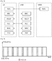
- FIG. 3 shows a block diagram of a user plane protocol stack of an LTE system.
- FIG. 4 shows a block diagram of a control plane protocol stack of an LTE system.
- Layers of a radio interface protocol between the UE and the E-UTRAN may be classified into a first layer (L1), a second layer (L2), and a third layer (L3) based on the lower three layers of the open system interconnection (OSI) model that is well-known in the communication system.
- OSI open system interconnection
- a physical (PHY) layer belongs to the L1.
- the PHY layer provides a higher layer with an information transfer service through a physical channel.
- the PHY layer is connected to a medium access control (MAC) layer, which is a higher layer of the PHY layer, through a transport channel.
- MAC medium access control
- a physical channel is mapped to the transport channel. Data between the MAC layer and the PHY layer is transferred through the transport channel.
- PHY physical
- a MAC layer, a radio link control (RLC) layer, and a packet data convergence protocol (PDCP) layer belong to the L2.
- the MAC layer provides services to the RLC layer, which is a higher layer of the MAC layer, via a logical channel.
- the MAC layer provides data transfer services on logical channels.
- the RLC layer supports the transmission of data with reliability. Meanwhile, a function of the RLC layer may be implemented with a functional block inside the MAC layer. In this case, the RLC layer may not exist.
- the PDCP layer provides a function of header compression function that reduces unnecessary control information such that data being transmitted by employing IP packets, such as IPv4 or IPv6, can be efficiently transmitted over a radio interface that has a relatively small bandwidth.
- the RLC and MAC layers may perform functions such as scheduling, automatic repeat request (ARQ), and hybrid ARQ (HARQ).
- the PDCP layer may perform the user plane functions such as header compression, integrity protection, and ciphering.
- the RLC and MAC layers may perform the same functions for the control plane.
- the RRC layer (terminated in the eNB on the network side) may perform functions such as broadcasting, paging, RRC connection management, RB control, mobility functions, and UE measurement reporting and controlling.
- the NAS control protocol (terminated in the MME of gateway on the network side) may perform functions such as a SAE bearer management, authentication, LTE_IDLE mobility handling, paging origination in LTE_IDLE, and security control for the signaling between the gateway and UE.
- FIG. 5 shows an example of a physical channel structure.
- a physical channel transfers signaling and data between PHY layer of the UE and eNB with a radio resource.
- a physical channel consists of a plurality of subframes in time domain and a plurality of subcarriers in frequency domain.
- One subframe which is 1 ms, consists of a plurality of symbols in the time domain.
- Specific symbol(s) of the subframe such as the first symbol of the subframe, may be used for a physical downlink control channel (PDCCH).
- the PDCCH carries dynamic allocated resources, such as a physical resource block (PRB) and modulation and coding scheme (MCS).
- PRB physical resource block
- MCS modulation and coding scheme
- a DL transport channel includes a broadcast channel (BCH) used for transmitting system information, a paging channel (PCH) used for paging a UE, a downlink shared channel (DL-SCH) used for transmitting user traffic or control signals, a multicast channel (MCH) used for multicast or broadcast service transmission.
- BCH broadcast channel
- PCH paging channel
- DL-SCH downlink shared channel
- MCH multicast channel
- the DL-SCH supports HARQ, dynamic link adaptation by varying the modulation, coding and transmit power, and both dynamic and semi-static resource allocation.
- the DL-SCH also may enable broadcast in the entire cell and the use of beamforming.
- a UL transport channel includes a random access channel (RACH) normally used for initial access to a cell, an uplink shared channel (UL-SCH) for transmitting user traffic or control signals, etc.
- RACH random access channel
- UL-SCH uplink shared channel
- the UL-SCH supports HARQ and dynamic link adaptation by varying the transmit power and potentially modulation and coding.
- the UL-SCH also may enable the use of beamforming.
- the logical channels are classified into control channels for transferring control plane information and traffic channels for transferring user plane information, according to a type of transmitted information. That is, a set of logical channel types is defined for different data transfer services offered by the MAC layer.
- the control channels are used for transfer of control plane information only.
- the control channels provided by the MAC layer include a broadcast control channel (BCCH), a paging control channel (PCCH), a common control channel (CCCH), a multicast control channel (MCCH) and a dedicated control channel (DCCH).
- the BCCH is a downlink channel for broadcasting system control information.
- the PCCH is a downlink channel that transfers paging information and is used when the network does not know the location cell of a UE.
- the CCCH is used by UEs having no RRC connection with the network.
- the MCCH is a point-to-multipoint downlink channel used for transmitting multimedia broadcast multicast services (MBMS) control information from the network to a UE.
- the DCCH is a point-to-point bi-directional channel used by UEs having an RRC connection that transmits dedicated control information between a UE and the network.
- Traffic channels are used for the transfer of user plane information only.
- the traffic channels provided by the MAC layer include a dedicated traffic channel (DTCH) and a multicast traffic channel (MTCH).
- DTCH dedicated traffic channel
- MTCH multicast traffic channel
- the DTCH is a point-to-point channel, dedicated to one UE for the transfer of user information and can exist in both uplink and downlink.
- the MTCH is a point-to-multipoint downlink channel for transmitting traffic data from the network to the UE.
- Uplink connections between logical channels and transport channels include the DCCH that can be mapped to the UL-SCH, the DTCH that can be mapped to the UL-SCH and the CCCH that can be mapped to the UL-SCH.
- Downlink connections between logical channels and transport channels include the BCCH that can be mapped to the BCH or DL-SCH, the PCCH that can be mapped to the PCH, the DCCH that can be mapped to the DL-SCH, and the DTCH that can be mapped to the DL-SCH, the MCCH that can be mapped to the MCH, and the MTCH that can be mapped to the MCH.
- An RRC state indicates whether an RRC layer of the UE is logically connected to an RRC layer of the E-UTRAN.
- the RRC state may be divided into two different states such as an RRC idle state (RRC_IDLE) and an RRC connected state (RRC_CONNECTED).
- RRC_IDLE the UE may receive broadcasts of system information and paging information while the UE specifies a discontinuous reception (DRX) configured by NAS, and the UE has been allocated an identification (ID) which uniquely identifies the UE in a tracking area and may perform public land mobile network (PLMN) selection and cell re-selection.
- ID identification
- PLMN public land mobile network
- the UE In RRC_CONNECTED, the UE has an E-UTRAN RRC connection and a context in the E-UTRAN, such that transmitting and/or receiving data to/from the eNB becomes possible. Also, the UE can report channel quality information and feedback information to the eNB.
- the E-UTRAN knows the cell to which the UE belongs. Therefore, the network can transmit and/or receive data to/from UE, the network can control mobility (handover and inter-radio access technologies (RAT) cell change order to GSM EDGE radio access network (GERAN) with network assisted cell change (NACC)) of the UE, and the network can perform cell measurements for a neighboring cell.
- RAT inter-radio access technologies
- GERAN GSM EDGE radio access network
- NACC network assisted cell change
- the UE specifies the paging DRX cycle. Specifically, the UE monitors a paging signal at a specific paging occasion of every UE specific paging DRX cycle.
- the paging occasion is a time interval during which a paging signal is transmitted.
- the UE has its own paging occasion.
- a paging message is transmitted over all cells belonging to the same tracking area. If the UE moves from one tracking area (TA) to another TA, the UE will send a tracking area update (TAU) message to the network to update its location.
- TAU tracking area update
- V2P service is a type of V2X service, where both parties of the communication are UEs using V2P application.
- V2N service is a type of V2X Service, where one party is a UE and the other party is a serving entity, both using V2N applications and communicating with each other via LTE network entities.
- E-UTRAN allows such UEs that are in proximity of each other to exchange V2V-related information using E-UTRA(N) when permission, authorization and proximity criteria are fulfilled.
- the proximity criteria can be configured by the mobile network operator (MNO).
- MNO mobile network operator
- UEs supporting V2V service can exchange such information when served by or not served by E-UTRAN which supports V2X Service.
- the UE supporting V2V applications transmits application layer information (e.g. about its location, dynamics, and attributes as part of the V2V service).
- the V2V payload must be flexible in order to accommodate different information contents, and the information can be transmitted periodically according to a configuration provided by the MNO.
- V2V is predominantly broadcast-based.
- V2V includes the exchange of V2V-related application information between distinct UEs directly and/or, due to the limited direct communication range of V2V, the exchange of V2V-related application information between distinct UEs via infrastructure supporting V2X service, e.g., RSU, application server, etc.
- infrastructure supporting V2X service e.g., RSU, application server, etc.
- E-UTRAN allows such UEs that are in proximity of each other to exchange V2P-related information using E-UTRAN when permission, authorization and proximity criteria are fulfilled.
- the proximity criteria can be configured by the MNO.
- UEs supporting V2P service can exchange such information even when not served by E-UTRAN which supports V2X Service.
- the UE supporting V2P applications transmits application layer information. Such information can be broadcast by a vehicle with UE supporting V2X service (e.g., warning to pedestrian), and/or by a pedestrian with UE supporting V2X service (e.g., warning to vehicle).
- V2P includes the exchange of V2P-related application information between distinct UEs (one for vehicle and the other for pedestrian) directly and/or, due to the limited direct communication range of V2P, the exchange of V2P-related application information between distinct UEs via infrastructure supporting V2X service, e.g., RSU, application server, etc.
- infrastructure supporting V2X service e.g., RSU, application server, etc.
- FIG. 6 shows an example of an architecture for V2X communication.
- the existing node i.e. eNB/MME
- new nodes may be deployed for supporting V2X communication.
- the interface between nodes may be S1/X2 interface or new interface. That is, the interface between eNB 1 and eNB2 may be X2 interface or new interface.
- the interface between eNB1/eNB2 and MME1/MME2 may be S1 interface or new interface.
- vehicle UE there may be two types of UE for V2X communication, one of which is a vehicle UE and the other is the RSU UE.
- the vehicle UE may be like the generic UE.
- the RSU UE is a RSU which is implemented in the UE, and can relay or multicast or broadcast the traffic or safety information or other vehicle UEs.
- vehicle UEs may be communicated with each other directly via PC5 interface.
- vehicle UEs may be communicated with each other indirectly via the network node.
- the network node may be one of an eNB, a new entity for V2X communication, a new gateway for V2X communication, a RSU, etc.
- the network node may not be the MME or S-GW.
- a vehicle UE may broadcast data, and the RSU UE may receive the broadcast data.
- the RSU and another vehicle UEs may be communicated with each other indirectly via the network node.
- the network node may be one of an eNB, a new entity for V2X communication, a new gateway for V2X communication, a RSU, etc. In this case, the network node may not be the MME or S-GW.
- RSU or V2X function may be deployed in some radio access network (RAN) nodes.
- RSU eNB which is a RSU implemented in the eNB
- the existing eNB may have V2X function. That is, some RAN nodes may support V2X function, and the other RAN nodes may not support V2X function.
- V2X information e.g. safety information
- the RAN nodes may not know where to forward the V2X information to, since the RAN nodes does not know which RAN nodes support V2X function. Referring to FIG.
- eNB1 when eNB1, which supports V2X function, receives V2X information from V-UE and/or RSU UE, eNB1 may forward the V2X information to neighbor eNBs, i.e. eNB2 and/or eNB3.
- neighbor eNBs i.e. eNB2 and/or eNB3.
- eNB1 since eNB1 cannot know which eNB supports V2X function or not, eNB1 may have to forward the V2X information to all neighbor eNBs regardless of whether receiving eNB supports V2X function or not. Therefore, signaling waste may happen.
- the present invention is proposed in order to solve the problem described above.
- FIG. 7 shows a method for indicating V2X function support according to an embodiment that is not claimed.
- the pre-configuration for V2X support is performed before receiving V2X information from V-UE and/or RSU-UE.
- a first RAN node (e.g. eNB1) transmits an X2 setup request message to a second RAN node (e.g. eNB2).
- the X2 setup request message may include an indication indicating that the first RAN node supports RSU/V2X function.
- the indication may be a new information element (IE) in the X2 setup request message.
- the second RAN node transmits an X2 setup response message to the first RAN nod, as a response to the X2 setup request message.
- the X2 setup response message may include an indication indicating that the second RAN node supports RSU/V2X function. The indication may be a new IE in the X2 setup response message.
- the first/second RAN node may perform action based on received parameters if V2X information is received from V-UE and/or RSU-UE.
- the V2X information may include at least one of safety information, traffic information, accident information, alarming, etc.
- the V2X information is not limited thereto, and the V2X information may include other various pieces of information in SA1 requirement.
- the indication is realized by an IE in the X2 setup/ response message during X2 setup procedure in the embodiment of FIG. 7 .
- the present invention is not limited thereto, i.e. the indication may be realized by a new message, or IE in a new message or an IE in the other existing message.
- the indication may be realized by an IE in the eNB configuration update message during the eNB configuration update procedure.
- FIG. 8 shows a method for indicating V2X function support according to an example for understanding the invention.
- the pre-configuration for V2X support is not performed before receiving V2X information from V-UE and/or RSU-UE.
- a first RAN node e.g. eNB1 transmits a message including V2X information to a second RAN node (e.g. eNB2).
- the V2X information may include at least one of safety information, traffic information, accident information, alarming, etc.
- the V2X information is not limited thereto, and the V2X information may include other various pieces of information in SA1 requirement.
- step S210 the second RAN node transmits a response message including a cause value to the first RAN node.
- the cause value may indicate that the second RAN node does not support RSU/V2X function.
- the first RAN node may not transmit the V2X information to the second RAN node again.
- FIG. 9 shows a communication system to implement an embodiment of the present invention.
- a second RAN node 900 may include a processor 910, a memory 920 and a transceiver 930.
- the processor 910 may be configured to implement proposed functions, procedures and/or methods described in this description. Layers of the radio interface protocol may be implemented in the processor 910.
- the memory 920 is operatively coupled with the processor 910 and stores a variety of information to operate the processor 910.
- the transceiver 930 is operatively coupled with the processor 910, and transmits and/or receives a radio signal.
- the processors 810, 910 may include application-specific integrated circuit (ASIC), other chipset, logic circuit and/or data processing device.
- the memories 820, 920 may include read-only memory (ROM), random access memory (RAM), flash memory, memory card, storage medium and/or other storage device.
- the transceivers 830, 930 may include baseband circuitry to process radio frequency signals.
- the techniques described herein can be implemented with modules (e.g., procedures, functions, and so on) that perform the functions described herein.
- the modules can be stored in memories 820, 920 and executed by processors 810, 910.
- the memories 820, 920 can be implemented within the processors 810, 910 or external to the processors 810, 910 in which case those can be communicatively coupled to the processors 810, 910 via various means as is known in the art.
Description
- The present invention relates to wireless communications, and more particularly, to a method and apparatus for supporting vehicle-to-everything (V2X) function for X2 procedure in a wireless communication system.
- 3rd generation partnership project (3GPP) long-term evolution (LTE) is a technology for enabling high-speed packet communications. Many schemes have been proposed for the LTE objective including those that aim to reduce user and provider costs, improve service quality, and expand and improve coverage and system capacity. The 3GPP LTE requires reduced cost per bit, increased service availability, flexible use of a frequency band, a simple structure, an open interface, and adequate power consumption of a terminal as an upper-level requirement.
- The pace of LTE network deployment is accelerating all over the world, which enables more and more advanced services and Internet applications making use of the inherent benefits of LTE, such as higher data rate, lower latency and enhanced coverage. Widely deployed LTE-based network provides the opportunity for the vehicle industry to realize the concept of 'connected cars'. By providing a vehicle with an access to the LTE network, a vehicle can be connected to the Internet and other vehicles so that a broad range of existing or new services can be envisaged. Vehicle manufacturers and cellular network operators show strong interests in vehicle wireless communications for proximity safety services as well as commercial applications. LTE-based vehicle-to-everything (V2X) study is urgently desired from market requirement, and the market for vehicle-to-vehicle (V2V) communication in particular is time sensitive. There are many research projects and field tests of connected vehicles in some countries or regions, such as US/Europe/Japan/Korea.
- V2X includes a vehicle-to-vehicle (V2V), covering LTE-based communication between vehicles, vehicle-to-pedestrian (V2P), covering LTE-based communication between a vehicle and a device carried by an individual (e.g. handheld terminal carried by a pedestrian, cyclist, driver or passenger), and vehicle-to-infrastructure/network (V2I), covering LTE-based communication between a vehicle and a roadside unit (RSU)/network. A RSU is a transportation infrastructure entity (e.g. an entity transmitting speed notifications) implemented in an eNodeB (eNB) or a stationary UE. By the introduction of V2X communication, a method for indicating whether to support V2X communication or not may be required.
-
EP 2815618 A1 discloses an Intelligent Transport System enabled cellular mobile network, comprising an infrastructure including a number of base stations, and a number of vehicles being equipped with both vehicle-to-vehicle and vehicle-to-infrastructure communication facilities, wherein particular events function as trigger for said vehicles to send event specific warning messages to their serving base station within said infrastructure, is characterized in that said base stations comprise an evaluation module being configured to analyze and categorize warning messages received from any of said vehicles according to predefinable criteria, and to estimate the number of vehicles that may be affected by the event related to a warning message, and a control module for performing uplink radio resource adaptation dependent on said warning message's category and said estimated number of affected vehicles. -
US 2014/051346 A1 discloses a communications system in which communications devices of users and communications devices of vehicular systems communicate safety messages through a cellular communications band or the DSRC (Dedicated short-range communications) vehicular communications band. - Huawei: "V2V terminology update on V2X enabled, vehicular UE, device on vehicle" , 3GPP S1-151061, proposes to use only the "UE" , "eNB", and "RSU" terminology for a 3GPP related specification, and to clarify the V2V or V2I terminology for each use case.
- The present invention provides a method for supporting vehicle-to-everything (V2X) function in a wireless communication system.
- The present invention is defined by the independent claim. Specific embodiments are defined by the dependent claims.
- Whether to support V2X function or not can be informed efficiently
-
-
FIG. 1 shows LTE system architecture. -
FIG. 2 shows a block diagram of architecture of a typical E-UTRAN and a typical EPC. -
FIG. 3 shows a block diagram of a user plane protocol stack of an LTE system. -
FIG. 4 shows a block diagram of a control plane protocol stack of an LTE system. -
FIG. 5 shows an example of a physical channel structure. -
FIG. 6 shows an example of an architecture for V2X communication. -
FIG. 7 shows a method for indicating V2X function support according to an embodiment of the present invention. -
FIG. 8 shows a method for indicating V2X function support according to an example for understanding the invention. -
FIG. 9 shows a communication system to implement an embodiment of the present invention. - The technology described below can be used in various wireless communication systems such as code division multiple access (CDMA), frequency division multiple access (FDMA), time division multiple access (TDMA), orthogonal frequency division multiple access (OFDMA), single carrier frequency division multiple access (SC-FDMA), etc. The CDMA can be implemented with a radio technology such as universal terrestrial radio access (UTRA) or CDMA-2000. The TDMA can be implemented with a radio technology such as global system for mobile communications (GSM)/general packet ratio service (GPRS)/enhanced data rate for GSM evolution (EDGE). The OFDMA can be implemented with a radio technology such as institute of electrical and electronics engineers (IEEE) 802.11 (Wi-Fi), IEEE 802.16 (WiMAX), IEEE 802-20, evolved UTRA (E-UTRA), etc. IEEE 802.16m is an evolution of IEEE 802.16e, and provides backward compatibility with an IEEE 802.16-based system. The UTRA is a part of a universal mobile telecommunication system (UMTS). 3rd generation partnership project (3GPP) long term evolution (LTE) is a part of an evolved UMTS (E-UMTS) using the E-UTRA. The 3GPP LTE uses the OFDMA in downlink and uses the SC-FDMA in uplink. LTE-advance (LTE-A) is an evolution of the 3GPP LTE.
- For clarity, the following description will focus on the LTE-A. However, technical features of the present invention are not limited thereto.
-
FIG. 1 shows LTE system architecture. The communication network is widely deployed to provide a variety of communication services such as voice over internet protocol (VoIP) through IMS and packet data. - Referring to
FIG. 1 , the LTE system architecture includes one or more user equipment (UE; 10), an evolved-UMTS terrestrial radio access network (E-UTRAN) and an evolved packet core (EPC). The UE 10 refers to a communication equipment carried by a user. The UE 10 may be fixed or mobile, and may be referred to as another terminology, such as a mobile station (MS), a user terminal (UT), a subscriber station (SS), a wireless device, etc. - The E-UTRAN includes one or more evolved node-B (eNB) 20, and a plurality of UEs may be located in one cell. The eNB 20 provides an end point of a control plane and a user plane to the UE 10. The eNB 20 is generally a fixed station that communicates with the UE 10 and may be referred to as another terminology, such as a base station (BS), an access point, etc. One eNB 20 may be deployed per cell.
- Hereinafter, a downlink (DL) denotes communication from the eNB 20 to the UE 10, and an uplink (UL) denotes communication from the UE 10 to the eNB 20. In the DL, a transmitter may be a part of the eNB 20, and a receiver may be a part of the UE 10. In the UL, the transmitter may be a part of the UE 10, and the receiver may be a part of the eNB 20.
- The EPC includes a mobility management entity (MME) and a serving gateway (S-GW). The MME/S-
GW 30 may be positioned at the end of the network. For clarity, MME/S-GW 30 will be referred to herein simply as a "gateway," but it is understood that this entity includes both the MME and S-GW. A packet data network (PDN) gateway (P-GW) may be connected to an external network. - The MME provides various functions including non-access stratum (NAS) signaling to eNBs 20, NAS signaling security, access stratum (AS) security control, inter core network (CN) node signaling for mobility between 3GPP access networks, idle mode UE reachability (including control and execution of paging retransmission), tracking area list management (for UE in idle and active mode), packet data network (PDN) gateway (P-GW) and S-GW selection, MME selection for handovers with MME change, serving GPRS support node (SGSN) selection for handovers to 2G or 3G 3GPP access networks, roaming, authentication, bearer management functions including dedicated bearer establishment, support for public warning system (PWS) (which includes earthquake and tsunami warning system (ETWS) and commercial mobile alert system (CMAS)) message transmission. The S-GW host provides assorted functions including per-user based packet filtering (by e.g., deep packet inspection), lawful interception, UE Internet protocol (IP) address allocation, transport level packet marking in the DL, UL and DL service level charging, gating and rate enforcement, DL rate enforcement based on access point name aggregate maximum bit rate (APN-AMBR).
- Interfaces for transmitting user traffic or control traffic may be used. The
UE 10 is connected to theeNB 20 via a Uu interface. TheeNBs 20 are connected to each other via an X2 interface. Neighboring eNBs may have a meshed network structure that has the X2 interface. A plurality of nodes may be connected between theeNB 20 and thegateway 30 via an S1 interface. -
FIG. 2 shows a block diagram of architecture of a typical E-UTRAN and a typical EPC. Referring toFIG. 2 , theeNB 20 may perform functions of selection forgateway 30, routing toward thegateway 30 during a radio resource control (RRC) activation, scheduling and transmitting of paging messages, scheduling and transmitting of broadcast channel (BCH) information, dynamic allocation of resources to theUEs 10 in both UL and DL, configuration and provisioning of eNB measurements, radio bearer control, radio admission control (RAC), and connection mobility control in LTE_ACTIVE state. In the EPC, and as noted above,gateway 30 may perform functions of paging origination, LTE_IDLE state management, ciphering of the user plane, SAE bearer control, and ciphering and integrity protection of NAS signaling. -
FIG. 3 shows a block diagram of a user plane protocol stack of an LTE system.FIG. 4 shows a block diagram of a control plane protocol stack of an LTE system. Layers of a radio interface protocol between the UE and the E-UTRAN may be classified into a first layer (L1), a second layer (L2), and a third layer (L3) based on the lower three layers of the open system interconnection (OSI) model that is well-known in the communication system. - A physical (PHY) layer belongs to the L1. The PHY layer provides a higher layer with an information transfer service through a physical channel. The PHY layer is connected to a medium access control (MAC) layer, which is a higher layer of the PHY layer, through a transport channel. A physical channel is mapped to the transport channel. Data between the MAC layer and the PHY layer is transferred through the transport channel. Between different PHY layers, i.e., between a PHY layer of a transmission side and a PHY layer of a reception side, data is transferred via the physical channel.
- A MAC layer, a radio link control (RLC) layer, and a packet data convergence protocol (PDCP) layer belong to the L2. The MAC layer provides services to the RLC layer, which is a higher layer of the MAC layer, via a logical channel. The MAC layer provides data transfer services on logical channels. The RLC layer supports the transmission of data with reliability. Meanwhile, a function of the RLC layer may be implemented with a functional block inside the MAC layer. In this case, the RLC layer may not exist. The PDCP layer provides a function of header compression function that reduces unnecessary control information such that data being transmitted by employing IP packets, such as IPv4 or IPv6, can be efficiently transmitted over a radio interface that has a relatively small bandwidth.
- A radio resource control (RRC) layer belongs to the L3. The RLC layer is located at the lowest portion of the L3, and is only defined in the control plane. The RRC layer controls logical channels, transport channels, and physical channels in relation to the configuration, reconfiguration, and release of radio bearers (RBs). The RB signifies a service provided the L2 for data transmission between the UE and E-UTRAN.
- Referring to
FIG. 3 , the RLC and MAC layers (terminated in the eNB on the network side) may perform functions such as scheduling, automatic repeat request (ARQ), and hybrid ARQ (HARQ). The PDCP layer (terminated in the eNB on the network side) may perform the user plane functions such as header compression, integrity protection, and ciphering. - Referring to
FIG. 4 , the RLC and MAC layers (terminated in the eNB on the network side) may perform the same functions for the control plane. The RRC layer (terminated in the eNB on the network side) may perform functions such as broadcasting, paging, RRC connection management, RB control, mobility functions, and UE measurement reporting and controlling. The NAS control protocol (terminated in the MME of gateway on the network side) may perform functions such as a SAE bearer management, authentication, LTE_IDLE mobility handling, paging origination in LTE_IDLE, and security control for the signaling between the gateway and UE. -
FIG. 5 shows an example of a physical channel structure. A physical channel transfers signaling and data between PHY layer of the UE and eNB with a radio resource. A physical channel consists of a plurality of subframes in time domain and a plurality of subcarriers in frequency domain. One subframe, which is 1 ms, consists of a plurality of symbols in the time domain. Specific symbol(s) of the subframe, such as the first symbol of the subframe, may be used for a physical downlink control channel (PDCCH). The PDCCH carries dynamic allocated resources, such as a physical resource block (PRB) and modulation and coding scheme (MCS). - A DL transport channel includes a broadcast channel (BCH) used for transmitting system information, a paging channel (PCH) used for paging a UE, a downlink shared channel (DL-SCH) used for transmitting user traffic or control signals, a multicast channel (MCH) used for multicast or broadcast service transmission. The DL-SCH supports HARQ, dynamic link adaptation by varying the modulation, coding and transmit power, and both dynamic and semi-static resource allocation. The DL-SCH also may enable broadcast in the entire cell and the use of beamforming.
- A UL transport channel includes a random access channel (RACH) normally used for initial access to a cell, an uplink shared channel (UL-SCH) for transmitting user traffic or control signals, etc. The UL-SCH supports HARQ and dynamic link adaptation by varying the transmit power and potentially modulation and coding. The UL-SCH also may enable the use of beamforming.
- The logical channels are classified into control channels for transferring control plane information and traffic channels for transferring user plane information, according to a type of transmitted information. That is, a set of logical channel types is defined for different data transfer services offered by the MAC layer.
- The control channels are used for transfer of control plane information only. The control channels provided by the MAC layer include a broadcast control channel (BCCH), a paging control channel (PCCH), a common control channel (CCCH), a multicast control channel (MCCH) and a dedicated control channel (DCCH). The BCCH is a downlink channel for broadcasting system control information. The PCCH is a downlink channel that transfers paging information and is used when the network does not know the location cell of a UE. The CCCH is used by UEs having no RRC connection with the network. The MCCH is a point-to-multipoint downlink channel used for transmitting multimedia broadcast multicast services (MBMS) control information from the network to a UE. The DCCH is a point-to-point bi-directional channel used by UEs having an RRC connection that transmits dedicated control information between a UE and the network.
- Traffic channels are used for the transfer of user plane information only. The traffic channels provided by the MAC layer include a dedicated traffic channel (DTCH) and a multicast traffic channel (MTCH). The DTCH is a point-to-point channel, dedicated to one UE for the transfer of user information and can exist in both uplink and downlink. The MTCH is a point-to-multipoint downlink channel for transmitting traffic data from the network to the UE.
- Uplink connections between logical channels and transport channels include the DCCH that can be mapped to the UL-SCH, the DTCH that can be mapped to the UL-SCH and the CCCH that can be mapped to the UL-SCH. Downlink connections between logical channels and transport channels include the BCCH that can be mapped to the BCH or DL-SCH, the PCCH that can be mapped to the PCH, the DCCH that can be mapped to the DL-SCH, and the DTCH that can be mapped to the DL-SCH, the MCCH that can be mapped to the MCH, and the MTCH that can be mapped to the MCH.
- An RRC state indicates whether an RRC layer of the UE is logically connected to an RRC layer of the E-UTRAN. The RRC state may be divided into two different states such as an RRC idle state (RRC_IDLE) and an RRC connected state (RRC_CONNECTED). In RRC_IDLE, the UE may receive broadcasts of system information and paging information while the UE specifies a discontinuous reception (DRX) configured by NAS, and the UE has been allocated an identification (ID) which uniquely identifies the UE in a tracking area and may perform public land mobile network (PLMN) selection and cell re-selection. Also, in RRC_IDLE, no RRC context is stored in the eNB.
- In RRC_CONNECTED, the UE has an E-UTRAN RRC connection and a context in the E-UTRAN, such that transmitting and/or receiving data to/from the eNB becomes possible. Also, the UE can report channel quality information and feedback information to the eNB. In RRC_CONNECTED, the E-UTRAN knows the cell to which the UE belongs. Therefore, the network can transmit and/or receive data to/from UE, the network can control mobility (handover and inter-radio access technologies (RAT) cell change order to GSM EDGE radio access network (GERAN) with network assisted cell change (NACC)) of the UE, and the network can perform cell measurements for a neighboring cell.
- In RRC_IDLE, the UE specifies the paging DRX cycle. Specifically, the UE monitors a paging signal at a specific paging occasion of every UE specific paging DRX cycle. The paging occasion is a time interval during which a paging signal is transmitted. The UE has its own paging occasion. A paging message is transmitted over all cells belonging to the same tracking area. If the UE moves from one tracking area (TA) to another TA, the UE will send a tracking area update (TAU) message to the network to update its location.
- Vehicle-to-everything (V2X) communication is described. V2X communication contains three different types, which are vehicle-to-vehicle (V2V) communications, vehicle-to-infrastructure (V2I) communications, and vehicle-to-pedestrian (V2P) communications. These three types of V2X can use "co-operative awareness" to provide more intelligent services for end-users. This means that transport entities, such as vehicles, roadside infrastructure, and pedestrians, can collect knowledge of their local environment (e.g. information received from other vehicles or sensor equipment in proximity) to process and share that knowledge in order to provide more intelligent services, such as cooperative collision warning or autonomous driving.
- V2X service is a type of communication service that involves a transmitting or receiving UE using V2V application via 3GPP transport. Based on the other party involved in the communication, it can be further divided into V2V service, V2I service, V2P service, and vehicle-to-network (V2N) service. V2V service is a type of V2X service, where both parties of the communication are UEs using V2V application. V2I service is a type of V2X Service, where one party is a UE and the other party is a road side unit (RSU) both using V2I application. The RSU is an entity supporting V2I service that can transmit to, and receive from a UE using V2I application. RSU is implemented in an eNB or a stationary UE. V2P service is a type of V2X service, where both parties of the communication are UEs using V2P application. V2N service is a type of V2X Service, where one party is a UE and the other party is a serving entity, both using V2N applications and communicating with each other via LTE network entities.
- For V2V, E-UTRAN allows such UEs that are in proximity of each other to exchange V2V-related information using E-UTRA(N) when permission, authorization and proximity criteria are fulfilled. The proximity criteria can be configured by the mobile network operator (MNO). However, UEs supporting V2V service can exchange such information when served by or not served by E-UTRAN which supports V2X Service. The UE supporting V2V applications transmits application layer information (e.g. about its location, dynamics, and attributes as part of the V2V service). The V2V payload must be flexible in order to accommodate different information contents, and the information can be transmitted periodically according to a configuration provided by the MNO. V2V is predominantly broadcast-based. V2V includes the exchange of V2V-related application information between distinct UEs directly and/or, due to the limited direct communication range of V2V, the exchange of V2V-related application information between distinct UEs via infrastructure supporting V2X service, e.g., RSU, application server, etc.
- For V2I, the UE supporting V2I applications sends application layer information to RSU. RSU sends application layer information to a group of UEs or a UE supporting V2I applications. V2N is also introduced where one party is a UE and the other party is a serving entity, both supporting V2N applications and communicating with each other via LTE network.
- For V2P, E-UTRAN allows such UEs that are in proximity of each other to exchange V2P-related information using E-UTRAN when permission, authorization and proximity criteria are fulfilled. The proximity criteria can be configured by the MNO. However, UEs supporting V2P service can exchange such information even when not served by E-UTRAN which supports V2X Service. The UE supporting V2P applications transmits application layer information. Such information can be broadcast by a vehicle with UE supporting V2X service (e.g., warning to pedestrian), and/or by a pedestrian with UE supporting V2X service (e.g., warning to vehicle). V2P includes the exchange of V2P-related application information between distinct UEs (one for vehicle and the other for pedestrian) directly and/or, due to the limited direct communication range of V2P, the exchange of V2P-related application information between distinct UEs via infrastructure supporting V2X service, e.g., RSU, application server, etc.
-
FIG. 6 shows an example of an architecture for V2X communication. Referring toFIG. 6 , the existing node (i.e. eNB/MME) or new nodes may be deployed for supporting V2X communication. The interface between nodes may be S1/X2 interface or new interface. That is, the interface betweeneNB 1 and eNB2 may be X2 interface or new interface. The interface between eNB1/eNB2 and MME1/MME2 may be S1 interface or new interface. - Further, there may be two types of UE for V2X communication, one of which is a vehicle UE and the other is the RSU UE. The vehicle UE may be like the generic UE. The RSU UE is a RSU which is implemented in the UE, and can relay or multicast or broadcast the traffic or safety information or other vehicle UEs. For V2X communication, vehicle UEs may be communicated with each other directly via PC5 interface. Alternatively, vehicle UEs may be communicated with each other indirectly via the network node. The network node may be one of an eNB, a new entity for V2X communication, a new gateway for V2X communication, a RSU, etc. The network node may not be the MME or S-GW. Alternatively, a vehicle UE may broadcast data, and the RSU UE may receive the broadcast data. The RSU and another vehicle UEs may be communicated with each other indirectly via the network node. The network node may be one of an eNB, a new entity for V2X communication, a new gateway for V2X communication, a RSU, etc. In this case, the network node may not be the MME or S-GW.
- Meanwhile, RSU or V2X function may be deployed in some radio access network (RAN) nodes. For example, RSU eNB, which is a RSU implemented in the eNB, may be deployed along with roadside. Or, the existing eNB may have V2X function. That is, some RAN nodes may support V2X function, and the other RAN nodes may not support V2X function. In this case, if a RAN nodes receives V2X information (e.g. safety information), the RAN nodes may not know where to forward the V2X information to, since the RAN nodes does not know which RAN nodes support V2X function. Referring to
FIG. 6 , when eNB1, which supports V2X function, receives V2X information from V-UE and/or RSU UE, eNB1 may forward the V2X information to neighbor eNBs, i.e. eNB2 and/or eNB3. However, since eNB1 cannot know which eNB supports V2X function or not, eNB1 may have to forward the V2X information to all neighbor eNBs regardless of whether receiving eNB supports V2X function or not. Therefore, signaling waste may happen. The present invention is proposed in order to solve the problem described above. -
FIG. 7 shows a method for indicating V2X function support according to an embodiment that is not claimed. In this embodiment, the pre-configuration for V2X support is performed before receiving V2X information from V-UE and/or RSU-UE. - In step S100, a first RAN node (e.g. eNB1) transmits an X2 setup request message to a second RAN node (e.g. eNB2). If the first RAN node supports RSU/V2X function, the X2 setup request message may include an indication indicating that the first RAN node supports RSU/V2X function. The indication may be a new information element (IE) in the X2 setup request message.
- In step S110, the second RAN node transmits an X2 setup response message to the first RAN nod, as a response to the X2 setup request message. If the second RAN node supports RSU/V2X function, the X2 setup response message may include an indication indicating that the second RAN node supports RSU/V2X function. The indication may be a new IE in the X2 setup response message.
- Upon receiving the indication included in the X2 setup request/response message, the first/second RAN node may perform action based on received parameters if V2X information is received from V-UE and/or RSU-UE. The V2X information may include at least one of safety information, traffic information, accident information, alarming, etc. However, the V2X information is not limited thereto, and the V2X information may include other various pieces of information in SA1 requirement.
- Further, it is described that the indication is realized by an IE in the X2 setup/ response message during X2 setup procedure in the embodiment of
FIG. 7 . However, the present invention is not limited thereto, i.e. the indication may be realized by a new message, or IE in a new message or an IE in the other existing message. For example, the indication may be realized by an IE in the eNB configuration update message during the eNB configuration update procedure. -
FIG. 8 shows a method for indicating V2X function support according to an example for understanding the invention. In this example, the pre-configuration for V2X support is not performed before receiving V2X information from V-UE and/or RSU-UE. - In step S200, a first RAN node (e.g. eNB1) transmits a message including V2X information to a second RAN node (e.g. eNB2). The V2X information may include at least one of safety information, traffic information, accident information, alarming, etc. However, the V2X information is not limited thereto, and the V2X information may include other various pieces of information in SA1 requirement.
- If the second RAN node does not support RSU/V2X function, in step S210, the second RAN node transmits a response message including a cause value to the first RAN node. The cause value may indicate that the second RAN node does not support RSU/V2X function.
- Upon receiving the response message including the cause value, the first RAN node may not transmit the V2X information to the second RAN node again.
-
FIG. 9 shows a communication system to implement an embodiment of the present invention. - A
first RAN node 800 may include aprocessor 810, amemory 820 and atransceiver 830. Theprocessor 810 may be configured to implement proposed functions, procedures and/or methods described in this description. Layers of the radio interface protocol may be implemented in theprocessor 810. Thememory 820 is operatively coupled with theprocessor 810 and stores a variety of information to operate theprocessor 810. Thetransceiver 830 is operatively coupled with theprocessor 810, and transmits and/or receives a radio signal. - A
second RAN node 900 may include aprocessor 910, amemory 920 and atransceiver 930. Theprocessor 910 may be configured to implement proposed functions, procedures and/or methods described in this description. Layers of the radio interface protocol may be implemented in theprocessor 910. Thememory 920 is operatively coupled with theprocessor 910 and stores a variety of information to operate theprocessor 910. Thetransceiver 930 is operatively coupled with theprocessor 910, and transmits and/or receives a radio signal. - The
processors memories transceivers memories processors memories processors processors processors - In view of the exemplary systems described herein, methodologies that may be implemented in accordance with the disclosed subject matter have been described with reference to several flow diagrams. While for purposed of simplicity, the methodologies are shown and described as a series of steps or blocks, it is to be understood and appreciated that the claimed subject matter is not limited by the order of the steps or blocks, as some steps may occur in different orders or concurrently with other steps from what is depicted and described herein. Moreover, one skilled in the art would understand that the steps illustrated in the flow diagram are not exclusive and other steps may be included or one or more of the steps in the example flow diagram may be deleted without affecting the scope of the present disclosure, which is defined by the appended claims.
Claims (3)
- A method performed by a first radio access network, RAN, node, eNB1, which is part of a wireless communication system, the method comprising:receiving vehicle-to-everything, V2X, information from a vehicle user equipment, UE; transmitting (S100) a first indication indicating support of V2X function of eNB1 to a second RAN node, eNB2; andreceiving (S110) a second indication from eNB2 indicating that eNB2 supports V2X function when eNB2 supports the V2X function; andforwarding the V2X information to eNB2 based on the second indication,wherein the V2X information includes at least one of traffic information, accident information and alarming related to V2X service.
- The method of claim 1, wherein the first indication corresponds to a new information element, IE, in an X2 setup request message.
- The method of claim 1, wherein the second indication corresponds to a new IE in an X2 setup response message.
Applications Claiming Priority (2)
| Application Number | Priority Date | Filing Date | Title |
|---|---|---|---|
| US201562195800P | 2015-07-23 | 2015-07-23 | |
| PCT/KR2016/008008 WO2017014592A1 (en) | 2015-07-23 | 2016-07-22 | Method and apparatus for supporting v2x function for x2 procedure in wireless communication system |
Publications (3)
| Publication Number | Publication Date |
|---|---|
| EP3326320A1 EP3326320A1 (en) | 2018-05-30 |
| EP3326320A4 EP3326320A4 (en) | 2019-03-06 |
| EP3326320B1 true EP3326320B1 (en) | 2020-09-16 |
Family
ID=57834226
Family Applications (1)
| Application Number | Title | Priority Date | Filing Date |
|---|---|---|---|
| EP16828096.4A Active EP3326320B1 (en) | 2015-07-23 | 2016-07-22 | Method and apparatus for supporting v2x function in wireless communication system |
Country Status (3)
| Country | Link |
|---|---|
| US (1) | US10764728B2 (en) |
| EP (1) | EP3326320B1 (en) |
| WO (1) | WO2017014592A1 (en) |
Families Citing this family (12)
| Publication number | Priority date | Publication date | Assignee | Title |
|---|---|---|---|---|
| EP3326320B1 (en) * | 2015-07-23 | 2020-09-16 | LG Electronics Inc. | Method and apparatus for supporting v2x function in wireless communication system |
| KR102279556B1 (en) * | 2015-09-18 | 2021-07-19 | 닛본 덴끼 가부시끼가이샤 | Base station, wireless terminal and method therefor |
| CN106658352B (en) * | 2015-11-02 | 2019-03-22 | 中兴通讯股份有限公司 | The retransmission method and device of car networking V2X business |
| JP6790371B2 (en) * | 2016-02-04 | 2020-11-25 | ソニー株式会社 | Communication device, communication method, transmitter and receiver |
| US11223932B2 (en) | 2017-01-31 | 2022-01-11 | Qualcomm Incorporated | Vehicle-to-everything feedback channel design |
| CN110710233B (en) * | 2017-05-30 | 2022-02-25 | 华为技术有限公司 | Apparatus and method for communication in a wireless communication network |
| US10880812B2 (en) * | 2018-07-23 | 2020-12-29 | Blackberry Limited | Vehicle-to-everything (V2X) service access |
| CN111585723B (en) * | 2019-02-15 | 2022-05-13 | 华为技术有限公司 | Auxiliary information and method and device for transmitting auxiliary information |
| CN110322729A (en) * | 2019-08-01 | 2019-10-11 | 公安部交通管理科学研究所 | Based on V2X traffic safety multidate information real-time release method and system |
| CN111540237B (en) * | 2020-05-19 | 2021-09-28 | 河北德冠隆电子科技有限公司 | Method for automatically generating vehicle safety driving guarantee scheme based on multi-data fusion |
| CN111932942A (en) * | 2020-08-28 | 2020-11-13 | 英华达(南京)科技有限公司 | Vehicle collision early warning method and device, terminal device and computer readable storage medium |
| CN113129643B (en) * | 2021-04-21 | 2022-12-27 | 亿咖通(湖北)技术有限公司 | Early warning method, system, device and storage medium |
Family Cites Families (11)
| Publication number | Priority date | Publication date | Assignee | Title |
|---|---|---|---|---|
| US8314718B2 (en) | 2009-10-02 | 2012-11-20 | GM Global Technology Operations LLC | Reducing the computational load on processors by selectively discarding data in vehicular networks |
| US20120038489A1 (en) | 2010-08-12 | 2012-02-16 | Goldshmidt Ehud | System and method for spontaneous p2p communication between identified vehicles |
| US9705991B2 (en) | 2012-07-04 | 2017-07-11 | Nec Corporation | Adaptation of radio resources allocation in an intelligent transport system enabled cellular mobile network and method for operating such network |
| US10077060B2 (en) * | 2012-07-11 | 2018-09-18 | Carnegie Mellon University | Railroad interlocking system with distributed control |
| US9048960B2 (en) * | 2012-08-17 | 2015-06-02 | Qualcomm Incorporated | Methods and apparatus for communicating safety message information |
| US9420410B2 (en) | 2013-09-10 | 2016-08-16 | General Motors Llc | Managing wireless voice and data communications |
| KR101502512B1 (en) * | 2013-11-26 | 2015-03-13 | 현대모비스 주식회사 | Automatic speed controlling system and method for vehicle |
| KR102441168B1 (en) * | 2015-05-08 | 2022-09-07 | 삼성전자주식회사 | Resource allocation apparatus and method for vehicle sevices |
| US10681501B2 (en) * | 2015-06-11 | 2020-06-09 | Lg Electronics Inc. | Method and apparatus for transmitting V2X message |
| CN107851378A (en) * | 2015-07-14 | 2018-03-27 | 三星电子株式会社 | Apparatus and method for providing service into all things on earth communication system in vehicle |
| EP3326320B1 (en) * | 2015-07-23 | 2020-09-16 | LG Electronics Inc. | Method and apparatus for supporting v2x function in wireless communication system |
-
2016
- 2016-07-22 EP EP16828096.4A patent/EP3326320B1/en active Active
- 2016-07-22 WO PCT/KR2016/008008 patent/WO2017014592A1/en active Application Filing
- 2016-07-22 US US15/746,394 patent/US10764728B2/en active Active
Non-Patent Citations (1)
| Title |
|---|
| None * |
Also Published As
| Publication number | Publication date |
|---|---|
| WO2017014592A1 (en) | 2017-01-26 |
| EP3326320A4 (en) | 2019-03-06 |
| EP3326320A1 (en) | 2018-05-30 |
| US20180199173A1 (en) | 2018-07-12 |
| US10764728B2 (en) | 2020-09-01 |
Similar Documents
| Publication | Publication Date | Title |
|---|---|---|
| EP3348101B1 (en) | Method and apparatus for allocating mbms based resources for v2x message transmission in wireless communication system | |
| EP3412087B1 (en) | Method and apparatus for allocating resources for v2x message transmission in wireless communication system | |
| EP3326320B1 (en) | Method and apparatus for supporting v2x function in wireless communication system | |
| US20200344756A1 (en) | Method and apparatus for performing user equipment triggered semi-persistent scheduling activation in wireless communication system | |
| US10091760B2 (en) | Method and apparatus for transmitting paging for V2X communication in wireless communication system | |
| US10524099B2 (en) | Method and apparatus for supporting bearer type for V2X communication in wireless communication system | |
| JP6615979B2 (en) | Method and apparatus for authenticating vehicle UE and RSU UE in a wireless communication system | |
| US20180332606A1 (en) | Method and apparatus for allocating common sps resource across multiple cells in wireless communication system | |
| US11889539B2 (en) | Method and apparatus for performing semi persistent scheduling transmission with scheduling request in wireless communication system | |
| US10142844B2 (en) | Method and apparatus for authorizing pedestrian user equipment in wireless communication system | |
| EP3500033A1 (en) | Method and apparatus for transmitting sps help information in wireless communication system |
Legal Events
| Date | Code | Title | Description |
|---|---|---|---|
| STAA | Information on the status of an ep patent application or granted ep patent |
Free format text: STATUS: THE INTERNATIONAL PUBLICATION HAS BEEN MADE |
|
| PUAI | Public reference made under article 153(3) epc to a published international application that has entered the european phase |
Free format text: ORIGINAL CODE: 0009012 |
|
| STAA | Information on the status of an ep patent application or granted ep patent |
Free format text: STATUS: REQUEST FOR EXAMINATION WAS MADE |
|
| 17P | Request for examination filed |
Effective date: 20180112 |
|
| AK | Designated contracting states |
Kind code of ref document: A1 Designated state(s): AL AT BE BG CH CY CZ DE DK EE ES FI FR GB GR HR HU IE IS IT LI LT LU LV MC MK MT NL NO PL PT RO RS SE SI SK SM TR |
|
| AX | Request for extension of the european patent |
Extension state: BA ME |
|
| DAV | Request for validation of the european patent (deleted) | ||
| DAX | Request for extension of the european patent (deleted) | ||
| RIC1 | Information provided on ipc code assigned before grant |
Ipc: H04L 5/00 20060101ALN20181026BHEP Ipc: H04W 24/02 20090101AFI20181026BHEP Ipc: H04W 92/20 20090101ALN20181026BHEP Ipc: H04W 76/14 20180101ALI20181026BHEP |
|
| A4 | Supplementary search report drawn up and despatched |
Effective date: 20190205 |
|
| RIC1 | Information provided on ipc code assigned before grant |
Ipc: H04W 24/02 20090101AFI20190130BHEP Ipc: H04L 5/00 20060101ALN20190130BHEP Ipc: H04W 76/14 20180101ALI20190130BHEP Ipc: H04W 92/20 20090101ALN20190130BHEP |
|
| REG | Reference to a national code |
Ref country code: DE Ref legal event code: R079 Ref document number: 602016044247 Country of ref document: DE Free format text: PREVIOUS MAIN CLASS: H04L0005000000 Ipc: H04W0092200000 |
|
| RIC1 | Information provided on ipc code assigned before grant |
Ipc: H04L 5/00 20060101ALN20200220BHEP Ipc: G08G 1/16 20060101ALN20200220BHEP Ipc: H04W 24/02 20090101ALN20200220BHEP Ipc: H04W 76/14 20180101ALN20200220BHEP Ipc: H04W 92/20 20090101AFI20200220BHEP |
|
| RIC1 | Information provided on ipc code assigned before grant |
Ipc: H04L 5/00 20060101ALN20200221BHEP Ipc: H04W 92/20 20090101AFI20200221BHEP Ipc: G08G 1/16 20060101ALN20200221BHEP Ipc: H04W 24/02 20090101ALN20200221BHEP Ipc: H04W 4/02 20180101ALN20200221BHEP Ipc: H04W 76/14 20180101ALN20200221BHEP |
|
| RIN1 | Information on inventor provided before grant (corrected) |
Inventor name: XU, JIAN Inventor name: BYUN, DAEWOOK |
|
| GRAP | Despatch of communication of intention to grant a patent |
Free format text: ORIGINAL CODE: EPIDOSNIGR1 |
|
| STAA | Information on the status of an ep patent application or granted ep patent |
Free format text: STATUS: GRANT OF PATENT IS INTENDED |
|
| INTG | Intention to grant announced |
Effective date: 20200423 |
|
| GRAS | Grant fee paid |
Free format text: ORIGINAL CODE: EPIDOSNIGR3 |
|
| GRAA | (expected) grant |
Free format text: ORIGINAL CODE: 0009210 |
|
| STAA | Information on the status of an ep patent application or granted ep patent |
Free format text: STATUS: THE PATENT HAS BEEN GRANTED |
|
| AK | Designated contracting states |
Kind code of ref document: B1 Designated state(s): AL AT BE BG CH CY CZ DE DK EE ES FI FR GB GR HR HU IE IS IT LI LT LU LV MC MK MT NL NO PL PT RO RS SE SI SK SM TR |
|
| REG | Reference to a national code |
Ref country code: GB Ref legal event code: FG4D |
|
| REG | Reference to a national code |
Ref country code: CH Ref legal event code: EP |
|
| REG | Reference to a national code |
Ref country code: DE Ref legal event code: R096 Ref document number: 602016044247 Country of ref document: DE |
|
| REG | Reference to a national code |
Ref country code: IE Ref legal event code: FG4D |
|
| REG | Reference to a national code |
Ref country code: AT Ref legal event code: REF Ref document number: 1315375 Country of ref document: AT Kind code of ref document: T Effective date: 20201015 |
|
| PG25 | Lapsed in a contracting state [announced via postgrant information from national office to epo] |
Ref country code: BG Free format text: LAPSE BECAUSE OF FAILURE TO SUBMIT A TRANSLATION OF THE DESCRIPTION OR TO PAY THE FEE WITHIN THE PRESCRIBED TIME-LIMIT Effective date: 20201216 Ref country code: HR Free format text: LAPSE BECAUSE OF FAILURE TO SUBMIT A TRANSLATION OF THE DESCRIPTION OR TO PAY THE FEE WITHIN THE PRESCRIBED TIME-LIMIT Effective date: 20200916 Ref country code: GR Free format text: LAPSE BECAUSE OF FAILURE TO SUBMIT A TRANSLATION OF THE DESCRIPTION OR TO PAY THE FEE WITHIN THE PRESCRIBED TIME-LIMIT Effective date: 20201217 Ref country code: NO Free format text: LAPSE BECAUSE OF FAILURE TO SUBMIT A TRANSLATION OF THE DESCRIPTION OR TO PAY THE FEE WITHIN THE PRESCRIBED TIME-LIMIT Effective date: 20201216 Ref country code: FI Free format text: LAPSE BECAUSE OF FAILURE TO SUBMIT A TRANSLATION OF THE DESCRIPTION OR TO PAY THE FEE WITHIN THE PRESCRIBED TIME-LIMIT Effective date: 20200916 Ref country code: SE Free format text: LAPSE BECAUSE OF FAILURE TO SUBMIT A TRANSLATION OF THE DESCRIPTION OR TO PAY THE FEE WITHIN THE PRESCRIBED TIME-LIMIT Effective date: 20200916 |
|
| REG | Reference to a national code |
Ref country code: AT Ref legal event code: MK05 Ref document number: 1315375 Country of ref document: AT Kind code of ref document: T Effective date: 20200916 |
|
| REG | Reference to a national code |
Ref country code: NL Ref legal event code: MP Effective date: 20200916 |
|
| PG25 | Lapsed in a contracting state [announced via postgrant information from national office to epo] |
Ref country code: RS Free format text: LAPSE BECAUSE OF FAILURE TO SUBMIT A TRANSLATION OF THE DESCRIPTION OR TO PAY THE FEE WITHIN THE PRESCRIBED TIME-LIMIT Effective date: 20200916 Ref country code: LV Free format text: LAPSE BECAUSE OF FAILURE TO SUBMIT A TRANSLATION OF THE DESCRIPTION OR TO PAY THE FEE WITHIN THE PRESCRIBED TIME-LIMIT Effective date: 20200916 |
|
| REG | Reference to a national code |
Ref country code: LT Ref legal event code: MG4D |
|
| PG25 | Lapsed in a contracting state [announced via postgrant information from national office to epo] |
Ref country code: CZ Free format text: LAPSE BECAUSE OF FAILURE TO SUBMIT A TRANSLATION OF THE DESCRIPTION OR TO PAY THE FEE WITHIN THE PRESCRIBED TIME-LIMIT Effective date: 20200916 Ref country code: RO Free format text: LAPSE BECAUSE OF FAILURE TO SUBMIT A TRANSLATION OF THE DESCRIPTION OR TO PAY THE FEE WITHIN THE PRESCRIBED TIME-LIMIT Effective date: 20200916 Ref country code: PT Free format text: LAPSE BECAUSE OF FAILURE TO SUBMIT A TRANSLATION OF THE DESCRIPTION OR TO PAY THE FEE WITHIN THE PRESCRIBED TIME-LIMIT Effective date: 20210118 Ref country code: LT Free format text: LAPSE BECAUSE OF FAILURE TO SUBMIT A TRANSLATION OF THE DESCRIPTION OR TO PAY THE FEE WITHIN THE PRESCRIBED TIME-LIMIT Effective date: 20200916 Ref country code: EE Free format text: LAPSE BECAUSE OF FAILURE TO SUBMIT A TRANSLATION OF THE DESCRIPTION OR TO PAY THE FEE WITHIN THE PRESCRIBED TIME-LIMIT Effective date: 20200916 Ref country code: SM Free format text: LAPSE BECAUSE OF FAILURE TO SUBMIT A TRANSLATION OF THE DESCRIPTION OR TO PAY THE FEE WITHIN THE PRESCRIBED TIME-LIMIT Effective date: 20200916 |
|
| PG25 | Lapsed in a contracting state [announced via postgrant information from national office to epo] |
Ref country code: AT Free format text: LAPSE BECAUSE OF FAILURE TO SUBMIT A TRANSLATION OF THE DESCRIPTION OR TO PAY THE FEE WITHIN THE PRESCRIBED TIME-LIMIT Effective date: 20200916 Ref country code: AL Free format text: LAPSE BECAUSE OF FAILURE TO SUBMIT A TRANSLATION OF THE DESCRIPTION OR TO PAY THE FEE WITHIN THE PRESCRIBED TIME-LIMIT Effective date: 20200916 Ref country code: ES Free format text: LAPSE BECAUSE OF FAILURE TO SUBMIT A TRANSLATION OF THE DESCRIPTION OR TO PAY THE FEE WITHIN THE PRESCRIBED TIME-LIMIT Effective date: 20200916 Ref country code: IS Free format text: LAPSE BECAUSE OF FAILURE TO SUBMIT A TRANSLATION OF THE DESCRIPTION OR TO PAY THE FEE WITHIN THE PRESCRIBED TIME-LIMIT Effective date: 20210116 Ref country code: PL Free format text: LAPSE BECAUSE OF FAILURE TO SUBMIT A TRANSLATION OF THE DESCRIPTION OR TO PAY THE FEE WITHIN THE PRESCRIBED TIME-LIMIT Effective date: 20200916 |
|
| REG | Reference to a national code |
Ref country code: DE Ref legal event code: R097 Ref document number: 602016044247 Country of ref document: DE |
|
| PG25 | Lapsed in a contracting state [announced via postgrant information from national office to epo] |
Ref country code: SK Free format text: LAPSE BECAUSE OF FAILURE TO SUBMIT A TRANSLATION OF THE DESCRIPTION OR TO PAY THE FEE WITHIN THE PRESCRIBED TIME-LIMIT Effective date: 20200916 |
|
| PLBE | No opposition filed within time limit |
Free format text: ORIGINAL CODE: 0009261 |
|
| STAA | Information on the status of an ep patent application or granted ep patent |
Free format text: STATUS: NO OPPOSITION FILED WITHIN TIME LIMIT |
|
| 26N | No opposition filed |
Effective date: 20210617 |
|
| PG25 | Lapsed in a contracting state [announced via postgrant information from national office to epo] |
Ref country code: SI Free format text: LAPSE BECAUSE OF FAILURE TO SUBMIT A TRANSLATION OF THE DESCRIPTION OR TO PAY THE FEE WITHIN THE PRESCRIBED TIME-LIMIT Effective date: 20200916 Ref country code: DK Free format text: LAPSE BECAUSE OF FAILURE TO SUBMIT A TRANSLATION OF THE DESCRIPTION OR TO PAY THE FEE WITHIN THE PRESCRIBED TIME-LIMIT Effective date: 20200916 |
|
| PG25 | Lapsed in a contracting state [announced via postgrant information from national office to epo] |
Ref country code: IT Free format text: LAPSE BECAUSE OF FAILURE TO SUBMIT A TRANSLATION OF THE DESCRIPTION OR TO PAY THE FEE WITHIN THE PRESCRIBED TIME-LIMIT Effective date: 20200916 |
|
| REG | Reference to a national code |
Ref country code: CH Ref legal event code: PL |
|
| GBPC | Gb: european patent ceased through non-payment of renewal fee |
Effective date: 20210722 |
|
| PG25 | Lapsed in a contracting state [announced via postgrant information from national office to epo] |
Ref country code: MC Free format text: LAPSE BECAUSE OF FAILURE TO SUBMIT A TRANSLATION OF THE DESCRIPTION OR TO PAY THE FEE WITHIN THE PRESCRIBED TIME-LIMIT Effective date: 20200916 |
|
| REG | Reference to a national code |
Ref country code: BE Ref legal event code: MM Effective date: 20210731 |
|
| PG25 | Lapsed in a contracting state [announced via postgrant information from national office to epo] |
Ref country code: LI Free format text: LAPSE BECAUSE OF NON-PAYMENT OF DUE FEES Effective date: 20210731 Ref country code: GB Free format text: LAPSE BECAUSE OF NON-PAYMENT OF DUE FEES Effective date: 20210722 Ref country code: CH Free format text: LAPSE BECAUSE OF NON-PAYMENT OF DUE FEES Effective date: 20210731 |
|
| PG25 | Lapsed in a contracting state [announced via postgrant information from national office to epo] |
Ref country code: LU Free format text: LAPSE BECAUSE OF NON-PAYMENT OF DUE FEES Effective date: 20210722 Ref country code: FR Free format text: LAPSE BECAUSE OF NON-PAYMENT OF DUE FEES Effective date: 20210731 |
|
| PG25 | Lapsed in a contracting state [announced via postgrant information from national office to epo] |
Ref country code: IE Free format text: LAPSE BECAUSE OF NON-PAYMENT OF DUE FEES Effective date: 20210722 Ref country code: BE Free format text: LAPSE BECAUSE OF NON-PAYMENT OF DUE FEES Effective date: 20210731 |
|
| PG25 | Lapsed in a contracting state [announced via postgrant information from national office to epo] |
Ref country code: HU Free format text: LAPSE BECAUSE OF FAILURE TO SUBMIT A TRANSLATION OF THE DESCRIPTION OR TO PAY THE FEE WITHIN THE PRESCRIBED TIME-LIMIT; INVALID AB INITIO Effective date: 20160722 |
|
| PG25 | Lapsed in a contracting state [announced via postgrant information from national office to epo] |
Ref country code: NL Free format text: LAPSE BECAUSE OF NON-PAYMENT OF DUE FEES Effective date: 20200923 Ref country code: CY Free format text: LAPSE BECAUSE OF FAILURE TO SUBMIT A TRANSLATION OF THE DESCRIPTION OR TO PAY THE FEE WITHIN THE PRESCRIBED TIME-LIMIT Effective date: 20200916 |
|
| PGFP | Annual fee paid to national office [announced via postgrant information from national office to epo] |
Ref country code: DE Payment date: 20230607 Year of fee payment: 8 |