EP3325213B1 - Sharpening apparatus for scissors - Google Patents
Sharpening apparatus for scissors Download PDFInfo
- Publication number
- EP3325213B1 EP3325213B1 EP16828256.4A EP16828256A EP3325213B1 EP 3325213 B1 EP3325213 B1 EP 3325213B1 EP 16828256 A EP16828256 A EP 16828256A EP 3325213 B1 EP3325213 B1 EP 3325213B1
- Authority
- EP
- European Patent Office
- Prior art keywords
- scissors
- sharpening
- steel
- pivotable
- sharpening steel
- Prior art date
- Legal status (The legal status is an assumption and is not a legal conclusion. Google has not performed a legal analysis and makes no representation as to the accuracy of the status listed.)
- Active
Links
- 229910000831 Steel Inorganic materials 0.000 claims description 228
- 239000010959 steel Substances 0.000 claims description 228
- 229910003460 diamond Inorganic materials 0.000 claims description 8
- 239000010432 diamond Substances 0.000 claims description 8
- 239000010935 stainless steel Substances 0.000 claims description 8
- 229910001220 stainless steel Inorganic materials 0.000 claims description 8
- 239000000758 substrate Substances 0.000 claims description 6
- 229910010293 ceramic material Inorganic materials 0.000 claims description 5
- 229910000760 Hardened steel Inorganic materials 0.000 claims description 4
- 229910001339 C alloy Inorganic materials 0.000 claims 2
- 239000000463 material Substances 0.000 description 20
- 229910052751 metal Inorganic materials 0.000 description 13
- 239000002184 metal Substances 0.000 description 13
- 239000000123 paper Substances 0.000 description 12
- 238000000034 method Methods 0.000 description 10
- 210000004209 hair Anatomy 0.000 description 8
- 235000013372 meat Nutrition 0.000 description 7
- 210000003811 finger Anatomy 0.000 description 6
- 235000013305 food Nutrition 0.000 description 4
- 239000004033 plastic Substances 0.000 description 4
- 238000010008 shearing Methods 0.000 description 4
- 210000003813 thumb Anatomy 0.000 description 4
- 238000009966 trimming Methods 0.000 description 4
- 239000000919 ceramic Substances 0.000 description 3
- 239000004744 fabric Substances 0.000 description 3
- 239000011888 foil Substances 0.000 description 3
- 230000005484 gravity Effects 0.000 description 3
- 239000002023 wood Substances 0.000 description 3
- OKTJSMMVPCPJKN-UHFFFAOYSA-N Carbon Chemical compound [C] OKTJSMMVPCPJKN-UHFFFAOYSA-N 0.000 description 2
- 241000196324 Embryophyta Species 0.000 description 2
- 241000357293 Leptobrama muelleri Species 0.000 description 2
- 241001465754 Metazoa Species 0.000 description 2
- 244000137852 Petrea volubilis Species 0.000 description 2
- 241000220317 Rosa Species 0.000 description 2
- 229910045601 alloy Inorganic materials 0.000 description 2
- 239000000956 alloy Substances 0.000 description 2
- 238000013459 approach Methods 0.000 description 2
- 229910052799 carbon Inorganic materials 0.000 description 2
- 239000011111 cardboard Substances 0.000 description 2
- 235000019506 cigar Nutrition 0.000 description 2
- 239000011521 glass Substances 0.000 description 2
- 238000012856 packing Methods 0.000 description 2
- 239000002245 particle Substances 0.000 description 2
- 238000005498 polishing Methods 0.000 description 2
- 235000013594 poultry meat Nutrition 0.000 description 2
- 238000012545 processing Methods 0.000 description 2
- 239000004753 textile Substances 0.000 description 2
- CDBYLPFSWZWCQE-UHFFFAOYSA-L Sodium Carbonate Chemical compound [Na+].[Na+].[O-]C([O-])=O CDBYLPFSWZWCQE-UHFFFAOYSA-L 0.000 description 1
- 229910000639 Spring steel Inorganic materials 0.000 description 1
- ATJFFYVFTNAWJD-UHFFFAOYSA-N Tin Chemical compound [Sn] ATJFFYVFTNAWJD-UHFFFAOYSA-N 0.000 description 1
- 206010044625 Trichorrhexis Diseases 0.000 description 1
- 239000003082 abrasive agent Substances 0.000 description 1
- 239000000853 adhesive Substances 0.000 description 1
- 230000001070 adhesive effect Effects 0.000 description 1
- 229910052782 aluminium Inorganic materials 0.000 description 1
- XAGFODPZIPBFFR-UHFFFAOYSA-N aluminium Chemical compound [Al] XAGFODPZIPBFFR-UHFFFAOYSA-N 0.000 description 1
- 239000010868 animal carcass Substances 0.000 description 1
- 238000010411 cooking Methods 0.000 description 1
- 201000010099 disease Diseases 0.000 description 1
- 208000037265 diseases, disorders, signs and symptoms Diseases 0.000 description 1
- 230000035622 drinking Effects 0.000 description 1
- 230000006870 function Effects 0.000 description 1
- -1 hair Substances 0.000 description 1
- 208000014674 injury Diseases 0.000 description 1
- 239000007769 metal material Substances 0.000 description 1
- 230000002093 peripheral effect Effects 0.000 description 1
- 244000144977 poultry Species 0.000 description 1
- 238000002360 preparation method Methods 0.000 description 1
- 238000013138 pruning Methods 0.000 description 1
- 238000009958 sewing Methods 0.000 description 1
- 229910001256 stainless steel alloy Inorganic materials 0.000 description 1
- 238000001356 surgical procedure Methods 0.000 description 1
- 230000003813 thin hair Effects 0.000 description 1
- 238000012549 training Methods 0.000 description 1
- 230000008733 trauma Effects 0.000 description 1
- 238000003466 welding Methods 0.000 description 1
- 210000002268 wool Anatomy 0.000 description 1
Images


Classifications
-
- B—PERFORMING OPERATIONS; TRANSPORTING
- B24—GRINDING; POLISHING
- B24D—TOOLS FOR GRINDING, BUFFING OR SHARPENING
- B24D15/00—Hand tools or other devices for non-rotary grinding, polishing, or stropping
- B24D15/06—Hand tools or other devices for non-rotary grinding, polishing, or stropping specially designed for sharpening cutting edges
- B24D15/063—Hand tools or other devices for non-rotary grinding, polishing, or stropping specially designed for sharpening cutting edges for grinding shears, scissors
-
- B—PERFORMING OPERATIONS; TRANSPORTING
- B24—GRINDING; POLISHING
- B24B—MACHINES, DEVICES, OR PROCESSES FOR GRINDING OR POLISHING; DRESSING OR CONDITIONING OF ABRADING SURFACES; FEEDING OF GRINDING, POLISHING, OR LAPPING AGENTS
- B24B3/00—Sharpening cutting edges, e.g. of tools; Accessories therefor, e.g. for holding the tools
- B24B3/36—Sharpening cutting edges, e.g. of tools; Accessories therefor, e.g. for holding the tools of cutting blades
- B24B3/52—Sharpening cutting edges, e.g. of tools; Accessories therefor, e.g. for holding the tools of cutting blades of shear blades or scissors
-
- B—PERFORMING OPERATIONS; TRANSPORTING
- B24—GRINDING; POLISHING
- B24D—TOOLS FOR GRINDING, BUFFING OR SHARPENING
- B24D15/00—Hand tools or other devices for non-rotary grinding, polishing, or stropping
- B24D15/02—Hand tools or other devices for non-rotary grinding, polishing, or stropping rigid; with rigidly-supported operative surface
-
- B—PERFORMING OPERATIONS; TRANSPORTING
- B24—GRINDING; POLISHING
- B24D—TOOLS FOR GRINDING, BUFFING OR SHARPENING
- B24D15/00—Hand tools or other devices for non-rotary grinding, polishing, or stropping
- B24D15/06—Hand tools or other devices for non-rotary grinding, polishing, or stropping specially designed for sharpening cutting edges
- B24D15/08—Hand tools or other devices for non-rotary grinding, polishing, or stropping specially designed for sharpening cutting edges of knives; of razors
- B24D15/081—Hand tools or other devices for non-rotary grinding, polishing, or stropping specially designed for sharpening cutting edges of knives; of razors with sharpening elements in interengaging or in mutual contact
Definitions
- This invention relates to an apparatus for sharpening the cutting edge of a scissors blade, and more specifically to such an apparatus that is hand-held and portable for simultaneously sharpening and polishing the interior and exterior surfaces of the cutting blades of the scissors without the need for a sharpening or honing wheel or a skilled scissors sharpener.
- Scissors represent a hand-operated shearing tool used for cutting various thin materials like paper, metal, foil, plastic, or rope. They also are employed by barbers, beauticians, and pet groomers to cut hair.
- Scissors consist of a pair of metal blades pivoted so that their sharpening edges slide against each other when the respective handles opposite to the pivot point are closed by the user's hand.
- the two blades having sharpened edges that cooperate when the scissor blades are closed to produce a precise cut along a material that needs to be cut.
- U.S. Patent No. 3,942,394 issued to Juranitch is directed to a finishing sharpener device specially designed for sharpening a knife blade. It includes a handle having a pair of wings extending therefrom. Each of the wings constitutes a flat bar defining a sharpening edge that is arcuate in cross section and smooth. By drawing a dulled knife blade cutting edge across the sharpening edge of one of the wings at the proper angle, the knife blade cutting edge may be restored to its sharpened configuration.
- the handle of the finishing sharpener serves as a guide for properly drawing the knife blade along the wing's sharpening edge.
- Razor Edge Systems of Ely, Minnesota has commercialized a SCISSORSAVER device useful for sharpening, steeling, or maintaining the cutting edges of scissors blades. particularly for use in the meat processing industry. It constitutes a sharpening steel that is engaged by the dulled blades of a scissors closed against the sharpening steel. It also has a vertical post for aligning the scissors blades and providing some sharpening functionality to the interior edge of the blades. The sharpening steel is positioned above the vertical post. so that when the sharpened scissors is removed from the SCISSORSAVER device, the upper sharpening steel falls by means of gravity to return to its standby position against the vertical post.
- this SCISSORSAVER device represents a relatively large, stationary-mounted apparatus that can be positioned in front of or next to a meat processing or factory assembly line worker. It is not particularly useful for barbers, beauticians, pet groomers, crafters, florists, or home users of scissors who would benefit from a small. portable sharpening device. Furthermore, this device must be carefully installed in such a position as to ensure that the upper sharpening steel will, in fact, fall back upon the lower vertical post when the scissors is removed from the device. Otherwise, the upper sharpening steel will not be available to sharpen again a pair of scissors
- a sharpening apparatus that may be used by a relatively unskilled person to simultaneously sharpen the interior and exterior surfaces of the cutting edge of both blades of a scissors by hand and with minimal effort and training.
- Such an apparatus should be small and portable so that the person may take it out to sharpen the cutting edge of the scissors blades when needed, as opposed to mounting the sharpening apparatus in a stationary location.
- the device should enable the sharpening of the blades of the scissors due to a simple closing of the scissors blades around the sharpening steels of the apparatus.
- the sharpening apparatus should automatically return itself from its sharpening position to its standby position without regard to the orientation of the device in three-dimensional space.
- Such a sharpening apparatus can be used to maintain an extremely sharp scissor edge for precise cutting of a material like hair without crushing or other damage with significantly reduced physical force and strain upon the user.
- the scissors sharpener comprises a main body having a top surface; a stationary sharpening steel having opposed surfaces that is securely attached to the main body; a bracket secured to the main body having a pivotably mounting assembly; a pivotable sharpening steel having a mounting plate connected to the pivotable mounting assembly; and a U-shaped return spring positioned between the bracket and the mounting plate of the pivotable sharpening steel.
- the stationary sharpening steel extends vertically above the top surface of the main body.
- the pivotable sharpening steel rotates with respect to the main body.
- the pivotable sharpening steel extends at an upwardly inclined angle in a vertical plane from the pivotable mounting assembly attached to the main body in order to reduce choking of the scissors blades as the pivotable sharpening steel travels along their cutting edges during the sharpening operation.
- the bracket mounted to the main body can also pivot with respect to the main body so that the pivotable sharpening steel rotates in a vertical plane while it is also pivoting in the horizontal plane during the scissors sharpening operation. This will further reduce potential chocking of the pivotable sharpening steel along the scissors blades during the sharpening operation.
- the pivotable sharpening steel preferably comprises a straight segment and two curved segments where the straight segment approaches a longitudinal axis at an angle, the first curved segment is bowed away from the longitudinal axis, and the second curved segment is bowed back towards the longitudinal axis. It has been found that this curved configuration of the pivotable sharpening steel produces a sharper cutting edge along the scissors blade. In another embodiment of the invention, the first curved segment can be bowed towards the longitudinal axis, while the second curved segment bows away from the longitudinal axis. It has been found that this cured curved configuration of the pivotable sharpening steel produces a stronger finish to the sharpened cutting edge of the blade. Two sharpening apparati having these different curved configurations for the pivotable sharpening steel may be used sequentially to sharpen the cutting edges of the scissors blades, and then strengthen their finish.
- a horizontal niche is formed within the top surface of the main body with the stationary sharpening steel being omitted.
- the horizontal niche is used to provide stable alignment of the scissors blades within the main body and with respect to the pivotable sharpening steel during the sharpening operation.
- the scissors blade cutting edges are sharpened by the pivotable sharpening steel as described above without the need to manipulate the scissors blades along a vertical stationary sharpening steel. This enables quicker engagement by the scissors blades with the sharpening apparatus to shorten the time required to sharpen their cutting edges.
- the scissors sharpening apparatus of the present invention is smaller and more portable than known prior art devices. Therefore, it may be conveniently accessed and used not only by a person using a scissors on a meat packing or factory assembly line, but also by users of scissors in less industrial settings like a barber, beautician, pet groomer, florist, or crafter. Moreover, the scissors sharpener apparatus may be used quickly and conveniently without reference to its position in three-dimensional space, because unlike prior art devices, gravity is not required to return the sharpening steel to its standby position after the pair of scissors is disengaged from the device.
- the scissors sharpener comprises a main body having a top surface; a stationary sharpening steel having opposed surfaces that is securely attached to the main body; a bracket secured to the main body having a pivotably mounting assembly; a pivotable sharpening steel having a mounting plate connected to the pivotable mounting assembly: and a U-shaped return spring positioned between the bracket and the mounting plate of the pivotable sharpening steel. While the stationary sharpening steel extends vertically above the top surface of the main body, the pivotable sharpening steel rotates with respect to the main body.
- the pivotable sharpening steel extends at an upwardly inclined angle in a vertical plane from the pivotable mounting assembly attached to the main body in order to reduce choking of the scissors blades as the pivotable sharpening steel travels along their cutting edges during the sharpening operation.
- the bracket mounted to the main body can also pivot with respect to the main body so that the pivotable sharpening steel rotates in a vertical plane while it is also pivoting in the horizontal plane during the scissors sharpening operation to further reduce potential chocking of the pivotable sharpening steel along the scissors blades during the sharpening operation.
- the pivotable sharpening steel preferably comprises a straight segment and two curved segments. If the first curved segment is bowed away from a longitudinal axis, while the second curved segment is bowed back towards the longitudinal axis. the pivotable sharpening steel produces a sharper cutting edge along the scissors blade. If the first curved segment is bowed towards the longitudinal axis, while the second curved segment bows away from the longitudinal axis, the pivotable sharpening steel produces a stronger finish to the sharpened cutting edge of the blade. Two sharpening apparati having these different curved configurations for the pivotable sharpening steel may be used sequentially to sharpen the cutting edges of the scissors blades, and then strengthen their finish.
- a horizontal niche may be formed within the top surface of the main body with the stationary sharpening steel being omitted.
- the horizontal niche is used to provide stable alignment of the scissors blades within the main body and with respect to the pivotable sharpening steel during the sharpening operation.
- the scissors blade cutting edges are sharpened by the pivotable sharpening steel as described above without the need to manipulate the scissors blades along a vertical stationary sharpening steel. This enables quicker engagement by the scissors blades with the sharpening apparatus to shorten the time required to sharpen their cutting edges.
- the scissors sharpening apparatus may be conveniently accessed and used by a person using a scissors on a meat packing or factory assembly line, as well as less industrial settings like a barber, beautician, pet groomer, florist, or crafter. Moreover, the scissors sharpener apparatus may be used quickly and conveniently without reference to its position in three-dimensional space, because unlike prior art devices, gravity is not required to return the sharpening steel to its standby position after the pair of scissors is disengaged from the device.
- cut substrate means a material such as hair, paper, cardboard, metal foil, thin plastic, textiles, cloth, silk, rope, twine, wire, wood veneers, wood, flowers, tree or plant part, or foods like meats that is capable of being cut or trimmed by a pair of scissors.
- “scissors” means a hand-operated shearing tool having a pair of metal blades pivoted between an opened and closed position with the blades sliding against each other by means of handles opposite to the pivot point. It includes, without limitation, conventional scissors, hair-cutting scissors for trimming hair, thinning scissors for thinning hair, blade shears for cutting animal's fleece to make wool, pet groomer's shears, hobby scissors for cutting or trimming cloth, paper, plastic, wood or other materials used in sewing or hobbies, hedge trimmers, gross shears, averruncators for trimming high branches from trees, pruning shears or secateurs for trimming small branches, loppers for cutting through large branches, metal or tin snips.
- scissors for separating meat from an animal carcass kitchen scissors or shears for food preparation, poultry shears for cutting cooked poultry meat, cigar cutters for cutting the tip off a cigar, nail scissors, trauma shears for emergency medical responders to cut clothing off a victim, surgical scissors for cutting human or animal flesh during surgery, and bandage scissors for cutting bandages.
- Figure 1 shows a pair of scissors 10 cutting a cut substrate in the form of a sheet of paper 12 along an intended cut line 14.
- the produced cut line 16 is shown behind the travel path of the scissors.
- the pair of scissors 10 is a hand-operated shearing tool that is shown more clearly in Fig. 2 . It consists of two metal blades 20 and 22 that are pivoted with respect to each other around a pivot point. A fastener 24 like a nut and bolt or rivet is used to secure the two blades together at this pivot point. Between this pivot point and the pointed tip 26 of blade 20 lies cutting edge 28 along its bottom blade surface. Likewise, cutting edge 30 lies along the top surface of blade 22 between the pivot point and its pointed tip 32. Attached to the opposite end of blades 20 and 22 are a pair of handles 34 and 36. For a right-handed person, the thumb is inserted through opening 38 in handle 36, while several fingers are inserted through opening 40 in handle 34.
- blades 20 and 22 When the person moves his thumb apart from the fingers to move handles 34 and 36 away from each other, blades 20 and 22 will likewise move apart from each other to move the scissors to its opened position. When the person moves his thumb and fingers together to close handles 34 and 36 against each other, then blades 20 and 22 will likewise come together and slide against each other so that sharpened edges 28 and 30 cut paper substrate 12.
- Figure 3 represents a cross-sectional view of scissors 10 with blade 20 and blade 22.
- Blade 20 has a flat inside surface 44, outside surface 46, beveled edge 48 in between and along the bottom surface of the blade, and cutting edge 28 defined by the point where beveled edge 48 meets inside surface 44.
- blade 22 has flat inside surface 50. outside surface 52, beveled edge 54 in between and along its top surface, and cutting edge 30 defined by the point where beveled edge 54 meets inside surface 50.
- blades 20 and 22 pivot so that inside surfaces 44 and 50. respectively, slide against each other with cutting edges 28 and 30 piercing paper 12 along the length of the portions of the blades that engage the paper.
- Beveled edges 48 and 54 of blades 20 and 22 act to push the cut edges 56 and 58 of the paper along cut line 16 away from each other to assist the cutting action of the scissors blades as they progress through paper substrate 12.
- cutting edge 28 and 30 on the blades 20 and 22 that need to be maintained in a sharpened state.
- cutting edge 30 along scissors blade 22 should be maintained in a state with a continuous, straight edge along the length of the blade. But through usage, especially if the scissors 10 are employed to shear a tough or abrasive cutting material 12, portions of the cutting edge may become deformed. Such deformation in the blade cutting edge 30 may create an inwardly deflected region 60 deviating towards vertical line A-A shown in Fig. 3 . Alternatively, such deformations in the blade cutting edge may create an outwardly deflected region 62 deviating away from vertical line A-A.
- Such deformations cause a "dulled edge" along the scissors blade that yields a poor cut by the scissors. Even more critically, a deformed region along the scissors blade may become worse in its deflection over time to the point that its metal separates from the scissors blade to form a burr 64 along the blade.
- Such inwardly deflected deformations 60 and burrs 64 can impede the scissors blades 20 and 22 from smoothly gliding past each other along their interior faces 44 and 50 to prevent the scissors from being opened and closed.
- the inwardly deflected deformations 60, outwardly deflected deformations 62, and burrs 64 along the scissors blade will crush the cut material 12 adjacent to cut line 16 as the scissors cut, instead of slicing or shearing the material with a neat and uniform cut line.
- the deformations and burrs may pull or crush the hair to produce pain and split ends in the person whose hair is being cut.
- these deformations and burrs can crush the cut edge of the stem to make the rose susceptible to disease and shorten the life of the flower.
- the scissors sharpener 70 of the present invention is shown in Fig. 5 . It comprises a main body 72 having a first end 71 and a second end 73. and end body portion 74 that combine to provide a body assembly 76 that is held by the user's hand 78.
- the blades 20 and 22 of scissors 10 are moved by the user's other hand (not shown) along vertical sharpening steel 80 and pivoting sharpening steel 82 to sharpen them.
- end body portion 74 may be connected to the distal end 73 of main body portion 72 by means of a plurality of connectors such as dowel pins 86 that are inserted into apertures 88 and 90 formed within the end body portion 74 and corresponding apertures (not shown) formed within main body portion 72.
- Other means such as screws or bolts and corresponding threaded holes, or adhesives or welding may be used instead to connect the two body portions together.
- a single, unitary body may also be employed.
- the end body portion 74 e.g., may be manufactured from a different material than the material used for the main body portion 72. or a different color than the color imparted to the main body portion to enhance the decorative appearance of the scissor sharpener 70.
- main body 72 Formed within the bottom surface 91 of main body 72 is indented, contoured surface 92 that may be grasped by the user's thumb 77. Meanwhile, semi-circular surfaces 94 and 96 formed within main body 72 and end body 74 portions, respectively, cooperate to form aperture 98 through which the user may insert her middle finger 70. Finally, the opposite end surface of end body portion 74 is contoured for being grasped by other fingers 81 of the user. A curved trigger 102 may also extend downwardly from end body portion 74 for being grasped by the user's ring finger 83. In this manner, the user can firmly and securely grasp the body assembly 76 of scissors sharpener 70 by her hand 78 to hold it in a stationary position while sliding the scissors blades 20 and 22 along the sharpening steels 80 and 82.
- main body 72 provides attachment surfaces for the stationery sharpening steel 80 and pivotable, curved sharpening steel 82. As shown more clearly in Figs. 7-8 , main body 72 contains a recessed niche 100 defined by side walls 102 and 104. back wall 106 (not shown), and bottom wall 108.
- Stationary sharpening steel 80 represents a honing steel, sometimes referred to as a “sharpening steel”, “sharpening rod”, “sharpening stick”, or (in the food or cooking industry) a “butcher's steel” or “chef's steel.” It comprises a rod made from hardened steel, stainless steel or stainless steel alloy, diamond-coated steel, or ceramic. In the case of stationery sharpening steel 80, it bears a flat cross-section characterized by two opposed faces 110 and two opposed edge surfaces 112. When made from a carbon-containing stainless steel material like 440C alloys (sourced, e.g., from Discount Steel of Minneapolis, Minnesota) or ceramic, it bears a smoothly, highly polished surface.
- 440C alloys sourced, e.g., from Discount Steel of Minneapolis, Minnesota
- the steel material When made from diamond-coated steels, the steel material is embedded with abrasive diamond particles. Suitable diamond-coated steel or ceramic materials may be sourced from Saint-Gobain Corporation of Courbevoie, France. But, the material from which the stationary sharpening steel 80 is fabricated must have a higher tensile strength than the metal from which the blades 20 and 22 of scissors 10 are made, or else be treated to a surface hardening process. In this manner, the functional performance of the stationary sharpening steel 80 is to realign a deformed edge 62 or 64 of the scissors blade when its length is moved along the sharpening steel 80. rather than to remove metal from the scissors blade edge.
- the stationary sharpening steel does not function like a grinding wheel, whetstone, or hone that is commonly used to remove metal burrs from a blade before it can be sharpened.
- Stationary sharpening steel 80 is fitted inside niche 100 formed within main body 72.
- a bolt or other fastener 116 is inserted through a hole (not shown) formed through the main body 72 secured at its other end by a nut (not shown).
- the width of opposed faces 110 of stationary sharpening steel 80 should substantially match the width of back wall 106 of niche 100 formed within main body 72 of the scissors sharpener 70.
- the width of edge surfaces 112 should be substantially less than the width of side walls 102 and 104 of the niche.
- stationary sharpening rod 80 fits in vertical orientation inside niche 100, so that its movement is arrested by side walls 102 and 104 as scissors blades are moved along the opposite faces 110 of the sharpening steel.
- sharpening steel 80 remains substantially stationary during use of the scissors sharpener 70.
- the pivotable, curved sharpening steel assembly 119 attached to the left side 136 of the main body 72 of the scissors sharpener 70 is the pivotable, curved sharpening steel assembly 119. It includes an L-shaped anchor bracket 120 that is connected to the lower right-side region 138 of main body 72. This anchor bracket has vertically disposed panels 122 and 124 which are joined to each other at a roughly perpendicular angle. Panel 122 has a hole 126 (not shown) formed therein for accommodating a bolt or other fastener 128 (see Fig. 7 ) which is inserted through hole 126 in panel 122, a corresponding round channel 130 (not shown) formed within main body 72, and secured by a nut 131 (not shown) along the left-hand side 136 of the main body.
- panel 122 of anchor bracket 120 is secured to the right-hand side of main body 72 with panel 124 extending in roughly parallel relationship across the front side surface 132 of the main body.
- Hole 134 is formed within panel 124 in a position that extends beyond the left-hand side 136 of the main body.
- Pivot base plate 140 constitutes an L-shaped bracket having panels 142 and 144 that are joined together in roughly perpendicular relation to each other.
- Panel 142 is vertically disposed and contains aperture 146.
- Panel 144 contains aperture 148 near its center and aperture 150 at a peripheral location on the panel (see Fig. 6 ).
- Bolt or other fastener 152 passes through aperture 134 in anchor bracket 120 and aperture 146 in pivot base plate 140 in conjunction with washer 154 and washer 156 and is secured at its other end by nut 158 (not shown) to connect the pivot base plate to the anchor bracket and in turn main body 72 of the scissors sharpener.
- Decorative cap 160 may be used to conceal bolt head 152.
- panel 144 of pivot base plate When attached, panel 144 of pivot base plate is positioned at an upwardly inclined angle with respect to the vertical side panel 136 of the main body 72. Moreover, this panel 44 may pivot up and down as the pivot base plate 140 rotates around the pivot axis provided by bolt fastener 152.
- Pivotable sharpening steel 82 comprises a curved sharpening steel arm 170 that is connected to pivot arm plate 172.
- This curved sharpening steel arm 170 and pivot arm plate 172 may be separate parts, or they may be one unitary part.
- Pivot arm plate 172 represents a flat, semi-circular piece having aperture 174 formed therein, and a cylindrical boss 176 extending downwardly from the plate.
- Sharpening steel arm 170 comprises a rod of steel or stainless steel, ceramic, or diamond-coated steel that is round or oval in cross-section.
- the length of the scissors blade determines the necessary length of the curved sharpening steel arm 170.
- scissors with 152,4 mm (six-inch) long blades will require a curved sharpening steel arm that is approximately 82,55 mm (3 1/4 inches) long.
- a longer curved sharpening steel arm is required for scissor blades longer than 152,4 mm (six inches).
- the curved regions on the sharpening steel arm 170 enable the sharpening steel arm to project a shorter lateral distance from pivot arm plate 170, while still providing necessary exterior surface area along which the scissors blades can travel during the sharpening process, than would be the case if the sharpening steel 170 was entirely straight.
- curved sharpening steel over 170 can be made from a hardened steel, stainless steel or stainless steel allow, diamond-coated steel, or ceramic material. It is preferably made from a carbon-containing stainless steel material like 440C alloy (sourced, e.g. from Discount Steel of Minneapolis, Minnesota) with a super smooth finish. It optionally may include a series of longitudinal ridges around its exterior surface.
- the curved sharpening steel arm 170 of pivotable sharpening steel 82 is roughly co-planar with the pivot arm plate 172.
- pivotable sharpening steel 82 is attached to pivot base plate 140, the upwardly inclined angle of pivot base plate 140 will cause sharpening steel arm 170 to extend at an upward incline in a vertical plane from the left side of the scissors sharpener 70 past the right side, forming an angle ⁇ of approximately 20-50 degrees, preferably 30-45 degrees, formed between the lower surface of the sharpening steel arm 170 and a line parallel to the bottom surface 91 of main body 72.
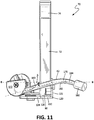
- Figure 11 presents a top plan view of scissors sharpener 70 showing the curved sharpening steel arm 170 in a horizontal plane. Longitudinal axis B-B roughly parallel to the front surface 132 of main body 72 of scissors sharpener 70 is also depicted.
- the sharpening steel arm 170 comprises three segments. First, a relatively straight segment 180 extends from pivot arm plate 172 at an angle ⁇ with respect to longitudinal B-B. Straight segment 180 passes over the top of the main body 72 of the scissors sharpener when the pivotable sharpening steel 82 is in its standby position shown in Fig. 11 . This relatively straight segment 180 turns into an outwardly bowed segment 182 with respect to the longitudinal axis B-B.
- this outwardly bowed segment 182 of the sharpening steel arm 170 turns into a bowed-back region 184 that turns in an arc back towards the front end 132 of the main body 172 and away from longitudinal axis B-B.
- An end cap 186 is attached to the end of this bowed-back region 184 of the sharpening steel arm 170 to provide an end-point for travel of the scissors blades 20 and 22 along the sharpening steel arm 170 during the sharpening operation.
- pivot sleeve 190 has an annular upper housing 192 and annular lower housing 194 with a collar 196 between the two housings.
- the collar has a larger diameter than that of the two housings.
- the interior surface 198 of annular upper housing is threaded.
- the interior surface 200 of annular lower housing is also threaded (not shown).
- Spring anchor plate 210 is shown in Figs. 6 and 13-14 . It comprises a semi-circular, flat panel 21 having a straight edge 212 and a circular edge 214. Aperture 216 is formed in panel 211 near straight edge 212. Extending downwardly from the bottom surface of panel 211 is cylindrical boss 218.
- Return spring 220 is shown in Fig. 6 and 15 . It comprises a U-shaped, curved strip 222 of metal material having the required combination of rigidity and elasticity to act like a spring. Central segment 224 is partially circular. First ear segment 226 comprising a nearly closed circle is connected to one end of the U-shaped central section 224. Second ear segment 228 also comprising a nearly closed circle is attached to the other end of the central section of the spring 220.
- Such a return spring is made from "spring steel" material which may be sourced from W.W. Grainger, Inc. of Lake Forest, Illinois, or McMaster-Carr Supply Company of Elmhurst, Illinois.
- pivotable sharpening steel assembly 119 In the assembled state of the pivotable sharpening steel assembly 119 (see Fig. 6 ).
- curved pivot arm plate 172 of pivotable sharpening steel 82 is positioned above pivot sleeve 190, which in turn is positioned above spring anchor plate 210.
- Return spring 220 is positioned between spring anchor plate 210 and upwardly inclined panel 144 of pivot base plate 140 which is connected to the main body 72 of scissors sharpener 70 by means of anchor bracket 120.
- Upper annular housing 192 of pivot sleeve 190 is inserted through aperture 174 in pivot arm plate 172 with bolt 230 screwed through aperture 174 from the top face of the pivot arm plate into engagement with internal threaded surface 198 of the pivot sleeve (see Fig. 12 ).
- lower annular housing 194 of pivot sleeve 190 is inserted through aperture 216 in spring anchor plate 210 (see Figs. 13-14 ), through the circular region 238 of return spring 220 defined by central segment 224, and through aperture 148 in upwardly inclined panel 144 of pivot base plate 140 (see Fig. 6 ).
- Bolt 232 is screwed through aperture 148 from the bottom face of panel 144 into engagement with interior threaded surface 200 (not shown) of the lower annular housing 194 of the pivot sleeve 190.
- Boss 218 which extends downwardly from the bottom face 211 of spring anchor plate 210 (see Fig. 14 ) passes through the open region 234 formed by first ear segment 226 of return spring 220, and then through aperture 150 (see Fig. 6 ) in upwardly inclined panel 144 of pivot base plate 140. In this manner, boss 218 provides an anchor point for the first ear segment end of the return spring 220.
- boss 176 which extends downwardly from the bottom face of pivot arm plate 172 bypasses spring anchor plate 210. extending past straight edge 212 of the spring anchor plate 210, and then passes through region 236 formed by second ear segment 228 of the return spring 220. The distal end 240 of boss 176 abuts the top surface of panel 144 of pivot base plate 140 without being secured to it.
- FIG. 20A the pivotable sharpening steel 82 is shown in its standby position with its curved sharpening steel arm 170 abutting or closely adjacent to stationary sharpening steel 80.
- the upwardly inclined angle ⁇ of the curved sharpening steel 170 is approximately 20-50 degrees in the vertical plane, preferably 30-45 degrees.
- a pair of scissors 10 is inserted with the interior faces 44 and 50 of blades 20 and 22 abutting exterior flat surfaces 110 of vertical stationary sharpening steel 80 with blade 20 above curved sharpening steel arm 170 and blade 22 below the curved sharpening steel arm (see Fig. 20A ).
- the curved sharpening steel arm 170 of pivotable sharpening steel 82 has the three segments: straight segment 180, outwardly bowed segment 182, and bowed-back segment 184.
- the straight segment 180 commences the travel of the sharpening steel arm 170 along the scissors blades 20 and 22 as the blades are closed against it by the user.
- this straight segment 180 should be about 25,4 - 88,9 mm (1-3 1/2 inches) long, preferably about 50,8 mm (2 inches) long.
- the back quarter of the scissors blades closest to the scissors pivot point will travel along this straight segment.
- the sharpening steel arm 170 will travel along the length of the scissors blades until end cap 186 reaches the scissors blades to terminate the travel of the arm 170.
- the outwardly bowed segment 182 of the sharpening steel arm 170 reaches the scissors blades
- the round profile of the sharpening steel starts to realign the outwardly displaced deformations 62 in scissors blades 20 and 22 (see Fig. 4 ) to sharpen the blades.
- the bowed-back segment 184 completes the task.
- Bowed-out segment 182 and bowed-back segment 184 provide the necessary gradual sweep of their exterior surfaces needed to accommodate the remaining three-quarters of the scissors blade length until the tip of the scissors blades contact the end cap 186 in order to sharpen the blades. If bowed-back segment 184 was straight instead of being bowed-back toward longitudinal axis B-B, the scissors blades would be choked off during the sharpening operation, which would destroy the blade edge.
- the bowed-out segment 182 of the curved sharpening steel 170 should be about 12,7 - 25,4 mm (1/2 - 1 inches) inches in length, preferably 19,05 mm (3/4 inch).
- the bowed-back segment 184 should be about 6,35 - 19,05 mm (1/4 - 3/4 inches) in length preferable 12,7 mm (1/2 inch).
- the flat outside surfaces 110 of vertical stationary sharpening steel 80 act to ensure that the inside edges of the scissors blades are properly aligned to avoid any further damage to the scissors blades, and to realign the inwardly displaced deformations 60 along the scissors blades.
- the outwardly bowed profile of this segment 182 of the pivotable sharpening steel arm 170 enhances this sharpening action, and causes the sharpening arm to move further along the scissors blades 20 and 22.
- the more sharply sloped angle of the bowed-back segment 184 of the sharpening steel arm 170 reduces choking of the scissors blades around the pivotable sharpening steel arm 170.
- the upwardly sloped angle ⁇ of the pivotable sharpening steel arm 170 in the vertical plane also reduces this choking phenomenon.
- return spring 220 is stretched with its first ear segment 226 anchored in place to panel 144 of pivot base plate 140 by boss 176, while its second ear segment 228 travels along the rotational path of pivot arm plate 172 which is attached to the pivotable sharpening steel arm 170.
- the memory incorporated into return spring 220 draws back second ear segment 228 to rotate pivot arm plate 172 via boss 176 back around the pivot axis defined by pivot sleeve 190 and to thereby draw the curved sharpening steel arm 170 of pivotable sharpening steel 82 back to its standby position adjacent to stationary sharpening steel 80 shown in Fig. 20A .
- the scissors sharpener is now ready to receive a scissor blade to further sharpen the same pair of scissors or to sharpen another pair of scissors.
- the structure of the scissors sharpener of the present invention therefore provides improved sharpening of both the interior and exterior surfaces of the scissors blades as the vertical sharpening steel 80 works in combination with the curved sharpening steel arm 170 which can pivot in three dimensional space both in a backwards and upwards direction.
- the return spring 220 enables the pivotable sharpening steel arm 170 to be automatically returned to its standby position upon disengagement of the scissors blades from the scissors sharpener without having to rely upon gravitational force, as many prior art bench top scissors sharpener devices do the scissors sharpener 70 can actually be used upside down.
- the scissors sharpener of the present invention to constitute a portable, hand-held model that can conveniently be used by a person in a work place without having to maintain the necessary spatial orientation of the curved sharpening steel to enable it to return to its standby position by gravitational force. There is also no need for the user to take the time to travel within the work place to an available bench top scissors sharpener.
- FIG. 21-22 Another embodiment of the scissors sharpener 240 of the present invention is shown in Figs. 21-22 . Its structure is similar to the scissors sharpener 70 embodiment described above, and like numbers are used for the similar elements of the scissors sharpener 240. The primary difference is the configuration of pivotable curved sharpening steel arm 242. Longitudinal axis C-C is depicted in Fig. 22 . When viewed in the horizontal plane shown in Fig. 22 , straight segment 244 is similar to straight segment 180 of the pivotable sharpening arm 170 of scissors sharpener 70, shown in Fig. 11 , and approaches longitudinal axis C-C at angle ⁇ . However, segment 246 shown in Fig.
- segment 22 is bowed inwardly towards the front edge 132 of the scissors sharpener main body 72 and away from longitudinal axis C-C, instead of being outwardly bowed like segment 182 shown in Fig. 11 .
- Segment 248 is also bowed away from longitudinal axis C ⁇ C, instead of being bowed back towards the front as in segment 184 shown in Fig. 11 .
- the length of straight segment 244 should be about 25.4-60.325 mm (1-2 3/8 inches), preferably about 38.1-44.45 mm (1 1/2-1 3/4 inches).
- the length ofbowed-in segment 246 should be about 12.7-31.75 mm (1/2-1 1/4 inches), preferably about 12.7 mm (1/2 inch).
- bowed-away segment 248 should be about 6.35-25.4 mm (1/4-1 inch), preferably about 12.7 mm (1/2 inch).
- This alternative curved profile for the pivotable curved sharpening steel arm 242 has been found to provide a stronger edge along the scissors blades 20 and 22.
- the first scissors sharpener embodiment 70 can be used to produce a sharp edge to the scissors blades.
- the same scissors can then be treated by the second scissors sharpener embodiment 240 to strengthen these sharpened blade edges so they last longer in use before becoming dull again.
- Still another embodiment 260 of the present invention is shown in Figs. 23 ⁇ 25B. Its structure is similar to the scissors sharpener 70 embodiment described above, and like numbers are used for the similar elements of the scissors sharpener 260. However, there is no stationary vertical sharpening steel 80 in the scissors sharpener 260 or vertical niche 100 for receiving such a vertical sharpening steel see Fig. 7 ). Instead, as shown in Fig. 23 . there is a horizontal niche 262 formed within the top surface 264 of the main body 72 of the scissors sharpener 260. This horizontal niche 262 has a first bottom surface 266. second bottom surface 268, and side wall 270. The first bottom surface is flat. Second bottom surface is also flat, but it is upwardly inclined with respect to the first bottom surface at an angle ⁇ with respect to the top surface 264. Angle ⁇ is about 10-20 degrees, preferably about 15 degrees.
- side wall 270 is inclined with respect to top surface 264 of main body 72 at angle ⁇ .
- Angle ⁇ is about 65-85 degrees, preferable 75 degrees.
- first bottom surface 266 is also upwardly inclined with respect to top surface 264.
- First bottom surface 266 meets side wall 270 at approximately a 90-degree angle.
- FIG. 25A the pivotable sharpening steel 82 is shown in its standby position with its curved sharpening steel area 170 forward towards the front of the scissors sharpener 260.
- a pair of scissors 10 is inserted with the blade 22 set into horizontal niche 262.
- the bottom of blade 22 rests on top of first bottom surface 266 and upwardly inclined second bottom surface 268. while exterior face 52 of blade 22 rests against inclined side wall 270.
- the portion of blade 22 closer to the tip is positioned below curved sharpening steel arm 170, while the portion of blade 20 is positioned above the curved sharpening steel arm 170.
- the curved sharpening steel arm 170 of pivotable sharpening steel 82 has the three segments: straight segment 180, outwardly bowed segment 182. and bowed-back segment 184.
- the straight segment 180 commences the travel of the sharpening steel arm 170 along the scissors blades 20 and 22 as the blades are closed against it by the user.
- this straight segment 180 should be about 25,4 - 88,9 mm (1 - 3 1/2 inches) long, preferably about 50,8 mm (2 inches) long.
- the back quarter of the scissors blades closest to the scissors pivot point will travel along this straight segment.
- the sharpening steel arm 170 will travel along the length of the scissors blades until end cap 186 reaches the scissors blades to terminate the travel of the arm 170.
- the outwardly bowed segment 182 of the sharpening steel arm 170 reaches the scissors blades
- the round profile of the sharpening steel starts to realign the outwardly displaced deformations 62 in scissors blades 20 and 22 (see Fig. 4 ) to sharpen the blades
- the bowed-back segment 184 completes the task.
- Bowed-out segment 182 and bowed-back segment 184 provide the necessary gradual sweep of their exterior surfaces needed to accommodate the remaining three-quarters of the scissors blade length until the tip of the scissors blades contact the end cap 186 in order to sharpen the blades. If bowed-back segment 184 was straight instead of being bowed-back toward longitudinal axis B-B, the scissors blades would be choked off during the sharpening operation, which would destroy the blade edge.
- the bowed-out segment 182 of the curved sharpening steel 170 should be about 12,7 - 25,4 mm (1/2 - 1 inches) in length, preferably 19,05 mm (3/4 inch).
- the bowed-back segment 184 should be about 6,35 - 19,05 mm (1/4 - 3/4 inches) in length preferable 12,7 mm (1/2 inch).
- the vertically-inclined side wall 270 and inclined first bottom surface 266 and second bottom surface 268 of horizontal niche 262 in main body 72 of scissors sharpener 260 provides stable orientation of scissors 10 to avoid any further damage to the scissors blades 20 and 22 while the blades engage the curved sharpening steel 170 to realign the inwardly displaced deformations 60 along the scissors blades.
- the scissors cutting edges get sharpened and polished, they in turn will act themselves to sharpen the inside edges of the blades. In this manner the stationary sharpening steel 80 of the first and second embodiments is unnecessary.
- This lack of the stationary sharpening steel 80 enables faster sharpening of a pair of scissors by the user, because the user does not need to engage the scissors blades with the stationary sharpening steel before engaging them with the curved sharpening steel 270.
- the outwardly bowed profile of this segment 182 of the pivotable sharpening steel arm 170 enhances this sharpening action, and causes the sharpening arm to move further along the scissors blades 20 and 22.
- the more sharply sloped angle of the bowed-back segment 184 of the sharpening steel arm 170 reduces choking of the scissors blades around the pivotable sharpening steel arm 170.
- the upwardly sloped angle ⁇ of the pivotable sharpening steel arm 170 in the vertical plane also reduces this choking phenomenon.
- return spring 220 is stretched with its first ear segment 226 anchored in place to panel 144 of pivot base plate 140 by boss 176, while its second ear segment 228 travels along the rotational path of pivot arm plate 172 which is attached to the pivotable sharpening steel arm 170.
- the memory incorporated into return spring 220 draws back second ear segment 228 to rotate pivot arm plate 172 via boss 176 back around the pivot axis defined by pivot sleeve 190 and to thereby draw the curved sharpening steel arm 170 of pivotable sharpening steel 82 back to its standby position adjacent to stationary sharpening steel 80 shown in Fig. 20A .
- the scissors sharpener is now ready to receive a scissor blade to further sharpen the same pair of scissors or to sharpen another pair of scissors.
- the structure of the scissors sharpener of this third embodiment therefore provides improved sharpening of both the interior and exterior surfaces of the scissors blades as the horizontal niche 260 works in combination with the curved sharpening steel arm 170 which can pivot in three dimensional space both in a backwards and upwards direction.
- the return spring 220 enables the pivotable sharpening steel arm 170 to be automatically returned to its standby position upon disengagement of the scissors blades from the scissors sharpener without having to rely upon gravitational force, as many prior art bench top scissors sharpener devices do the scissors sharpener 70 can actually be used upside down.
- the scissors sharpener of the present invention to constitute a portable, hand-held model that can conveniently be used by a person in a work place without having to maintain the necessary spatial orientation of the curved sharpening steel to enable it to return to its standby position by gravitational force. There is also no need for the user to take the time to travel within the work place to an available bench top scissors sharpener.
- the curved sharpening steel 242 of the second embodiment can be substituted for the curved sharpening steel 170 in this third embodiment in order to strengthen the cutting edges of the scissors blades 20 and 22 after they have been sharpened.
Description
- This invention relates to an apparatus for sharpening the cutting edge of a scissors blade, and more specifically to such an apparatus that is hand-held and portable for simultaneously sharpening and polishing the interior and exterior surfaces of the cutting blades of the scissors without the need for a sharpening or honing wheel or a skilled scissors sharpener.
- Scissors represent a hand-operated shearing tool used for cutting various thin materials like paper, metal, foil, plastic, or rope. They also are employed by barbers, beauticians, and pet groomers to cut hair.
- Scissors consist of a pair of metal blades pivoted so that their sharpening edges slide against each other when the respective handles opposite to the pivot point are closed by the user's hand. The two blades having sharpened edges that cooperate when the scissor blades are closed to produce a precise cut along a material that needs to be cut.
- But, over time, these sharpened edges of the scissors blades will become dull. Moreover, tougher or abrasive materials will cause the blades to become dull more quickly. Dull blades do not cut as easily or precisely, and can create a danger to the end user by requiring greater hand force to make a cut. Moreover, dulled blades can include rolled edges, burrs, or ragged edges with regions along the cutting surface that are out of alignment with each other. Such misaligned blades can damage the material being cut.
- Therefore, such dulled scissors blades must be periodically sharpened. Typically. grinding wheels or whetstones have been used to restore the cutting edges along the blades of scissors. But, this constitutes a precise operation in which the angle of the cutting edge of the blade must match the angle of the whetstone or grinding wheel surface. It is easy to damage the cutting edge of the scissors blade further if the sharpening exercise is performed poorly. Thus. most scissors users need to send out their dulled scissors to a professional sharpening service, or to replace the scissors with a new pair of scissors. This can be time-consuming and expensive.
- Other scissors users have been known to employ more humble methods for sharpening dulled scissors blades. For example, taking a pair of scissors and cutting three strips of sand paper allegedly will restore some degree of sharpness to the cutting edges due to the movement of the cutting edges against the abrasive particles on the sand paper. Other "home-grown" methods for sharpening scissors blades include cutting a pin while sliding it forward along the scissors blades, cutting a couple of strips of aluminum foil that are folded multiple times to produce a thick stack, or pushing the scissors blades against the exterior surface of a glass cylinder like a drinking glass or soda bottle while closing the scissors. However, while these methods do not require expensive equipment or technical skill, they are believed to do a better job of polishing an already-sharpened scissors blade than sharpening the blade itself.
-
U.S. Patent No. 3,942,394 issued to Juranitch is directed to a finishing sharpener device specially designed for sharpening a knife blade. It includes a handle having a pair of wings extending therefrom. Each of the wings constitutes a flat bar defining a sharpening edge that is arcuate in cross section and smooth. By drawing a dulled knife blade cutting edge across the sharpening edge of one of the wings at the proper angle, the knife blade cutting edge may be restored to its sharpened configuration. The handle of the finishing sharpener serves as a guide for properly drawing the knife blade along the wing's sharpening edge. But, this process still requires some skill by the person sharpening the knife blade to ensure a proper match of the knife blade cutting edge angle with the angled surface of the sharpening edge of the wing. Moreover, the arcuate cross-section surface of relatively small radial extent having a highly smooth configuration is insufficient for removing material from the cutting edge of the knife blade. This finishing sharpener may only be used after the knife blade is sharpened first on a hone or grinding wheel. - Razor Edge Systems of Ely, Minnesota has commercialized a SCISSORSAVER device useful for sharpening, steeling, or maintaining the cutting edges of scissors blades. particularly for use in the meat processing industry. It constitutes a sharpening steel that is engaged by the dulled blades of a scissors closed against the sharpening steel. It also has a vertical post for aligning the scissors blades and providing some sharpening functionality to the interior edge of the blades. The sharpening steel is positioned above the vertical post. so that when the sharpened scissors is removed from the SCISSORSAVER device, the upper sharpening steel falls by means of gravity to return to its standby position against the vertical post. But, this SCISSORSAVER device represents a relatively large, stationary-mounted apparatus that can be positioned in front of or next to a meat processing or factory assembly line worker. It is not particularly useful for barbers, beauticians, pet groomers, crafters, florists, or home users of scissors who would benefit from a small. portable sharpening device. Furthermore, this device must be carefully installed in such a position as to ensure that the upper sharpening steel will, in fact, fall back upon the lower vertical post when the scissors is removed from the device. Otherwise, the upper sharpening steel will not be available to sharpen again a pair of scissors
- The above described scissors sharpener is disclosed in document
US D 686 895 S - Therefore, it would be very advantageous to provide a sharpening apparatus that may be used by a relatively unskilled person to simultaneously sharpen the interior and exterior surfaces of the cutting edge of both blades of a scissors by hand and with minimal effort and training. Such an apparatus should be small and portable so that the person may take it out to sharpen the cutting edge of the scissors blades when needed, as opposed to mounting the sharpening apparatus in a stationary location. Moreover. the device should enable the sharpening of the blades of the scissors due to a simple closing of the scissors blades around the sharpening steels of the apparatus. Furthermore, the sharpening apparatus should automatically return itself from its sharpening position to its standby position without regard to the orientation of the device in three-dimensional space. Such a sharpening apparatus can be used to maintain an extremely sharp scissor edge for precise cutting of a material like hair without crushing or other damage with significantly reduced physical force and strain upon the user.
- An apparatus for sharpening the blades of a pair of scissors is provided according to claim 1. The scissors sharpener comprises a main body having a top surface; a stationary sharpening steel having opposed surfaces that is securely attached to the main body; a bracket secured to the main body having a pivotably mounting assembly; a pivotable sharpening steel having a mounting plate connected to the pivotable mounting assembly; and a U-shaped return spring positioned between the bracket and the mounting plate of the pivotable sharpening steel. The stationary sharpening steel extends vertically above the top surface of the main body. The pivotable sharpening steel rotates with respect to the main body. When a user inserts a pair of scissors so that the inside surfaces of the two blades abut the opposed surfaces of the stationary sharpening steel, and the blades extend beyond the vertical sharpening steel positioned above and below the pivotable sharpening steel, the blades are closed against the pivotable sharpening steel to rotate the pivotable sharpening steel in a horizontal plane with respect to the main body to travel from its standby position along the blade cutting edges, while the vertical sharpening steel provides stable alignment of the scissors with respect to the scissors sharpening apparatus and sharpens the interior of the cutting edges. When the scissors blades are disengaged from the scissors sharpening apparatus, the return spring will bias the pivotable sharpening steel back to its standby position to be ready for sharpening the next pair of scissors.
- The pivotable sharpening steel extends at an upwardly inclined angle in a vertical plane from the pivotable mounting assembly attached to the main body in order to reduce choking of the scissors blades as the pivotable sharpening steel travels along their cutting edges during the sharpening operation. The bracket mounted to the main body can also pivot with respect to the main body so that the pivotable sharpening steel rotates in a vertical plane while it is also pivoting in the horizontal plane during the scissors sharpening operation. This will further reduce potential chocking of the pivotable sharpening steel along the scissors blades during the sharpening operation.
- The pivotable sharpening steel preferably comprises a straight segment and two curved segments where the straight segment approaches a longitudinal axis at an angle, the first curved segment is bowed away from the longitudinal axis, and the second curved segment is bowed back towards the longitudinal axis. It has been found that this curved configuration of the pivotable sharpening steel produces a sharper cutting edge along the scissors blade. In another embodiment of the invention, the first curved segment can be bowed towards the longitudinal axis, while the second curved segment bows away from the longitudinal axis. It has been found that this cured curved configuration of the pivotable sharpening steel produces a stronger finish to the sharpened cutting edge of the blade. Two sharpening apparati having these different curved configurations for the pivotable sharpening steel may be used sequentially to sharpen the cutting edges of the scissors blades, and then strengthen their finish.
- In still another embodiment of an alternative scissors sharpening apparatus according to claim 2, a horizontal niche is formed within the top surface of the main body with the stationary sharpening steel being omitted. The horizontal niche is used to provide stable alignment of the scissors blades within the main body and with respect to the pivotable sharpening steel during the sharpening operation. The scissors blade cutting edges are sharpened by the pivotable sharpening steel as described above without the need to manipulate the scissors blades along a vertical stationary sharpening steel. This enables quicker engagement by the scissors blades with the sharpening apparatus to shorten the time required to sharpen their cutting edges.
- The scissors sharpening apparatus of the present invention is smaller and more portable than known prior art devices. Therefore, it may be conveniently accessed and used not only by a person using a scissors on a meat packing or factory assembly line, but also by users of scissors in less industrial settings like a barber, beautician, pet groomer, florist, or crafter. Moreover, the scissors sharpener apparatus may be used quickly and conveniently without reference to its position in three-dimensional space, because unlike prior art devices, gravity is not required to return the sharpening steel to its standby position after the pair of scissors is disengaged from the device.
- In the accompanying drawings:
-
Figure 1 is a perspective view of a pair of scissors cutting a flat material like a piece of paper; -
Figure 2 is a perspective view of a pair of scissors in an opened position; -
Figure 3 is a cross-sectional view of the two blades of a pair of scissors in a partially closed position cutting the piece of paper; -
Figure 4 is a perspective view of a pair of scissors in an opened position with deformed edges and burrs along the blade; -
Figure 5 is a perspective view of the scissors sharpening device of the present invention with the user's hand and scissors blades shown in phantom lines; -
Figure 6 is an exploded view of the scissors sharpener ofFigure 5 ; -
Figure 7 is a perspective view of the scissors sharpener ofFigure 5 from the opposite point of view; -
Figure 8 is a left side elevational view of the scissors sharpener ofFigure 5 ; -
Figure 9 is a front elevational view of the scissors sharpener ofFigure 5 ; -
Figure 10 is a back elevational view of the scissors sharpener ofFigure 5 ; -
Figure 11 is a top plan view of the scissors sharpener ofFigure 5 ; -
Figure 12 is a perspective view of the pivot sleeve for the scissors sharpener; -
Figure 13 is a perspective view of the top surface of the spring anchor plate for the scissors sharpener; -
Figure 14 is a perspective view of the bottom surface of the spring anchor plate ofFigure 13 ; -
Figure 15 is a perspective view of the return spring of the scissors sharpener; -
Figure 16 is a perspective view of the curved sharpening steel assembly, stationary sharpening steel, and anchor bracket portions of the scissors sharpener ofFigure 5 ; -
Figure 17 is a perspective view of the curved sharpening steel assembly ofFigure 16 with the spring anchor plate shown in phantom lines; -
Figure 18 is a perspective view of the curved sharpening steel assembly ofFigure 16 with the anchor bracket shown in phantom lines; -
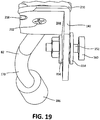
Figure 19 is a perspective view of the anchor bracket assembly with the spring anchor plate attached to it; -
Figure 20A is a partial perspective view of the scissors sharpener ofFigure 5 with the scissor blades starting the sharpening process; -
Figure 20B is a partial perspective view of the scissors sharpener ofFigure 20A with the scissors blades further progressed through the sharpening process; -
Figure 21 is a perspective view of a second embodiment of the scissors sharpener device of the present invention; -
Figure 22 is a top plan view of the scissors sharpener ofFigure 21 ; -
Figure 23 is a perspective view of a third embodiment of the scissors sharpener of the present invention with a longitudinal niche in lieu of the vertical stationery sharpening steel; -
Figure 24 is a front elevational view of the scissors sharpener ofFigure 23 ; -
Figure 25A is a partial perspective view of the scissors sharpener ofFigure 23 with the scissors blades starting the sharpening process; and -
Figure 25B is a partial perspective view of the scissors sharpener ofFigure 25A with the scissors blades further progressed through the sharpening process. - A small and portable apparatus for the sharpening the blades of a pair of scissors is provided according to the invention. The scissors sharpener comprises a main body having a top surface; a stationary sharpening steel having opposed surfaces that is securely attached to the main body; a bracket secured to the main body having a pivotably mounting assembly; a pivotable sharpening steel having a mounting plate connected to the pivotable mounting assembly: and a U-shaped return spring positioned between the bracket and the mounting plate of the pivotable sharpening steel. While the stationary sharpening steel extends vertically above the top surface of the main body, the pivotable sharpening steel rotates with respect to the main body. When a user inserts a pair of scissors so that the inside surfaces of the two blades abut the opposed surfaces of the stationary sharpening steel, and the blades extend beyond the vertical sharpening steel positioned above and below the pivotable sharpening steel, the blades are closed against the pivotable sharpening steel to rotate the pivotable sharpening steel in a horizontal plane with respect to the main body to travel from its standby position along the blade cutting edges. The vertical sharpening steel provides stable alignment of the scissors with respect to the scissors sharpening apparatus and sharpens the interior of the cutting edges. When the scissors blades are disengaged from the scissors sharpening apparatus, the return spring will bias the pivotable sharpening steel back to its standby position to be ready for sharpening the next pair of scissors.
- The pivotable sharpening steel extends at an upwardly inclined angle in a vertical plane from the pivotable mounting assembly attached to the main body in order to reduce choking of the scissors blades as the pivotable sharpening steel travels along their cutting edges during the sharpening operation. The bracket mounted to the main body can also pivot with respect to the main body so that the pivotable sharpening steel rotates in a vertical plane while it is also pivoting in the horizontal plane during the scissors sharpening operation to further reduce potential chocking of the pivotable sharpening steel along the scissors blades during the sharpening operation.
- The pivotable sharpening steel preferably comprises a straight segment and two curved segments. If the first curved segment is bowed away from a longitudinal axis, while the second curved segment is bowed back towards the longitudinal axis. the pivotable sharpening steel produces a sharper cutting edge along the scissors blade. If the first curved segment is bowed towards the longitudinal axis, while the second curved segment bows away from the longitudinal axis, the pivotable sharpening steel produces a stronger finish to the sharpened cutting edge of the blade. Two sharpening apparati having these different curved configurations for the pivotable sharpening steel may be used sequentially to sharpen the cutting edges of the scissors blades, and then strengthen their finish.
- In still another embodiment of the scissors sharpening apparatus, a horizontal niche may be formed within the top surface of the main body with the stationary sharpening steel being omitted. The horizontal niche is used to provide stable alignment of the scissors blades within the main body and with respect to the pivotable sharpening steel during the sharpening operation. The scissors blade cutting edges are sharpened by the pivotable sharpening steel as described above without the need to manipulate the scissors blades along a vertical stationary sharpening steel. This enables quicker engagement by the scissors blades with the sharpening apparatus to shorten the time required to sharpen their cutting edges.
- The scissors sharpening apparatus may be conveniently accessed and used by a person using a scissors on a meat packing or factory assembly line, as well as less industrial settings like a barber, beautician, pet groomer, florist, or crafter. Moreover, the scissors sharpener apparatus may be used quickly and conveniently without reference to its position in three-dimensional space, because unlike prior art devices, gravity is not required to return the sharpening steel to its standby position after the pair of scissors is disengaged from the device.
- For purposes of the present invention, "cut substrate" means a material such as hair, paper, cardboard, metal foil, thin plastic, textiles, cloth, silk, rope, twine, wire, wood veneers, wood, flowers, tree or plant part, or foods like meats that is capable of being cut or trimmed by a pair of scissors.
- As used within this Application, "scissors" means a hand-operated shearing tool having a pair of metal blades pivoted between an opened and closed position with the blades sliding against each other by means of handles opposite to the pivot point. It includes, without limitation, conventional scissors, hair-cutting scissors for trimming hair, thinning scissors for thinning hair, blade shears for cutting animal's fleece to make wool, pet groomer's shears, hobby scissors for cutting or trimming cloth, paper, plastic, wood or other materials used in sewing or hobbies, hedge trimmers, gross shears, averruncators for trimming high branches from trees, pruning shears or secateurs for trimming small branches, loppers for cutting through large branches, metal or tin snips. scissors for separating meat from an animal carcass, kitchen scissors or shears for food preparation, poultry shears for cutting cooked poultry meat, cigar cutters for cutting the tip off a cigar, nail scissors, trauma shears for emergency medical responders to cut clothing off a victim, surgical scissors for cutting human or animal flesh during surgery, and bandage scissors for cutting bandages.
-
Figure 1 shows a pair ofscissors 10 cutting a cut substrate in the form of a sheet ofpaper 12 along an intendedcut line 14. The producedcut line 16 is shown behind the travel path of the scissors. - The pair of
scissors 10 is a hand-operated shearing tool that is shown more clearly inFig. 2 . It consists of twometal blades fastener 24 like a nut and bolt or rivet is used to secure the two blades together at this pivot point. Between this pivot point and the pointedtip 26 ofblade 20lies cutting edge 28 along its bottom blade surface. Likewise, cuttingedge 30 lies along the top surface ofblade 22 between the pivot point and itspointed tip 32. Attached to the opposite end ofblades handles handle 36, while several fingers are inserted through opening 40 inhandle 34. When the person moves his thumb apart from the fingers to movehandles blades handles blades edges paper substrate 12. -
Figure 3 represents a cross-sectional view ofscissors 10 withblade 20 andblade 22.Blade 20 has a flatinside surface 44, outsidesurface 46, bevelededge 48 in between and along the bottom surface of the blade, and cuttingedge 28 defined by the point wherebeveled edge 48 meets insidesurface 44. Similarly,blade 22 has flatinside surface 50. outsidesurface 52, bevelededge 54 in between and along its top surface, and cuttingedge 30 defined by the point wherebeveled edge 54 meets insidesurface 50. When thescissors 10 is moved by the user to its closed position,blades edges paper 12 along the length of the portions of the blades that engage the paper. Beveled edges 48 and 54 ofblades cut line 16 away from each other to assist the cutting action of the scissors blades as they progress throughpaper substrate 12. - Thus, it is cutting
edge blades Fig. 4 , cuttingedge 30 alongscissors blade 22 should be maintained in a state with a continuous, straight edge along the length of the blade. But through usage, especially if thescissors 10 are employed to shear a tough orabrasive cutting material 12, portions of the cutting edge may become deformed. Such deformation in theblade cutting edge 30 may create an inwardly deflectedregion 60 deviating towards vertical line A-A shown inFig. 3 . Alternatively, such deformations in the blade cutting edge may create an outwardly deflectedregion 62 deviating away from vertical line A-A. Such deformations cause a "dulled edge" along the scissors blade that yields a poor cut by the scissors. Even more critically, a deformed region along the scissors blade may become worse in its deflection over time to the point that its metal separates from the scissors blade to form aburr 64 along the blade. Such inwardly deflecteddeformations 60 andburrs 64 can impede thescissors blades deformations 60, outwardly deflecteddeformations 62, andburrs 64 along the scissors blade will crush thecut material 12 adjacent to cutline 16 as the scissors cut, instead of slicing or shearing the material with a neat and uniform cut line. Furthermore, if thescissors 10 is used to cut hair, the deformations and burrs may pull or crush the hair to produce pain and split ends in the person whose hair is being cut. Likewise, if the scissors are used to cut the stem of, e.g., a rose, these deformations and burrs can crush the cut edge of the stem to make the rose susceptible to disease and shorten the life of the flower. - While a piece of
paper 12 has been shown as the piece of cut material sheared by the scissors for the sake of illustration, a number of other types of cut material like hair, flowers, cardboard, metal fork, plastic, textiles, cloth, silk, rope, twine, wire, wood veneers, tree or plant parts, or meat or other foods are commonly sheared by scissors, and should be understood as being fully covered by the scope of this invention. - The scissors sharpener 70 of the present invention is shown in
Fig. 5 . It comprises amain body 72 having afirst end 71 and asecond end 73. and endbody portion 74 that combine to provide abody assembly 76 that is held by the user'shand 78. Theblades scissors 10 are moved by the user's other hand (not shown) along vertical sharpeningsteel 80 and pivoting sharpeningsteel 82 to sharpen them. - As shown more clearly in
Fig. 6 ,end body portion 74 may be connected to thedistal end 73 ofmain body portion 72 by means of a plurality of connectors such as dowel pins 86 that are inserted intoapertures end body portion 74 and corresponding apertures (not shown) formed withinmain body portion 72. Other means such as screws or bolts and corresponding threaded holes, or adhesives or welding may be used instead to connect the two body portions together. A single, unitary body may also be employed. By using two separate body portions, however, theend body portion 74, e.g., may be manufactured from a different material than the material used for themain body portion 72. or a different color than the color imparted to the main body portion to enhance the decorative appearance of thescissor sharpener 70. - Formed within the
bottom surface 91 ofmain body 72 is indented, contouredsurface 92 that may be grasped by the user'sthumb 77. Meanwhile,semi-circular surfaces main body 72 andend body 74 portions, respectively, cooperate to formaperture 98 through which the user may insert hermiddle finger 70. Finally, the opposite end surface ofend body portion 74 is contoured for being grasped byother fingers 81 of the user. Acurved trigger 102 may also extend downwardly fromend body portion 74 for being grasped by the user's ring finger 83. In this manner, the user can firmly and securely grasp thebody assembly 76 of scissors sharpener 70 by herhand 78 to hold it in a stationary position while sliding thescissors blades steels - The
first end 71 ofmain body 72 provides attachment surfaces for thestationery sharpening steel 80 and pivotable, curved sharpeningsteel 82. As shown more clearly inFigs. 7-8 ,main body 72 contains a recessedniche 100 defined byside walls bottom wall 108. - Stationary sharpening
steel 80 represents a honing steel, sometimes referred to as a "sharpening steel", "sharpening rod", "sharpening stick", or (in the food or cooking industry) a "butcher's steel" or "chef's steel." It comprises a rod made from hardened steel, stainless steel or stainless steel alloy, diamond-coated steel, or ceramic. In the case ofstationery sharpening steel 80, it bears a flat cross-section characterized by twoopposed faces 110 and two opposed edge surfaces 112. When made from a carbon-containing stainless steel material like 440C alloys (sourced, e.g., from Discount Steel of Minneapolis, Minnesota) or ceramic, it bears a smoothly, highly polished surface. Optionally, it may include a plurality of longitudinal ridges. When made from diamond-coated steels, the steel material is embedded with abrasive diamond particles. Suitable diamond-coated steel or ceramic materials may be sourced from Saint-Gobain Corporation of Courbevoie, France. But, the material from which the stationary sharpeningsteel 80 is fabricated must have a higher tensile strength than the metal from which theblades scissors 10 are made, or else be treated to a surface hardening process. In this manner, the functional performance of the stationary sharpeningsteel 80 is to realign adeformed edge steel 80. rather than to remove metal from the scissors blade edge. When pressure is applied on the scissors blade against the hard sharpening steel, it will cause the blade's metal to yield to the harder sharpening steel metal or ceramic material to become realigned and sharpened. Yet, the steel surface must be super smooth in order to avoid further damage and deformation caused by the sharpening steel for the scissors blade that could create unwanted burrs along the blade edge. Thus, the stationary sharpening steel does not function like a grinding wheel, whetstone, or hone that is commonly used to remove metal burrs from a blade before it can be sharpened. - Stationary sharpening
steel 80 is fitted insideniche 100 formed withinmain body 72. A bolt orother fastener 116 is inserted through a hole (not shown) formed through themain body 72 secured at its other end by a nut (not shown). The width of opposed faces 110 of stationary sharpeningsteel 80 should substantially match the width of back wall 106 ofniche 100 formed withinmain body 72 of thescissors sharpener 70. At the same time, the width of edge surfaces 112 should be substantially less than the width ofside walls rod 80 fits in vertical orientation insideniche 100, so that its movement is arrested byside walls steel 80 remains substantially stationary during use of thescissors sharpener 70. - Returning to
Fig. 6 , attached to theleft side 136 of themain body 72 of thescissors sharpener 70 is the pivotable, curved sharpeningsteel assembly 119. It includes an L-shapedanchor bracket 120 that is connected to the lower right-side region 138 ofmain body 72. This anchor bracket has vertically disposedpanels Panel 122 has a hole 126 (not shown) formed therein for accommodating a bolt or other fastener 128 (seeFig. 7 ) which is inserted through hole 126 inpanel 122, a corresponding round channel 130 (not shown) formed withinmain body 72, and secured by a nut 131 (not shown) along the left-hand side 136 of the main body. In this manner,panel 122 ofanchor bracket 120 is secured to the right-hand side ofmain body 72 withpanel 124 extending in roughly parallel relationship across thefront side surface 132 of the main body. Hole 134 (seeFig. 6 ) is formed withinpanel 124 in a position that extends beyond the left-hand side 136 of the main body. - Pivot
base plate 140 constitutes an L-shapedbracket having panels Panel 142 is vertically disposed and containsaperture 146.Panel 144 containsaperture 148 near its center andaperture 150 at a peripheral location on the panel (seeFig. 6 ). Bolt orother fastener 152 passes throughaperture 134 inanchor bracket 120 andaperture 146 inpivot base plate 140 in conjunction withwasher 154 andwasher 156 and is secured at its other end by nut 158 (not shown) to connect the pivot base plate to the anchor bracket and in turnmain body 72 of the scissors sharpener.Decorative cap 160 may be used to concealbolt head 152. When attached,panel 144 of pivot base plate is positioned at an upwardly inclined angle with respect to thevertical side panel 136 of themain body 72. Moreover, thispanel 44 may pivot up and down as thepivot base plate 140 rotates around the pivot axis provided bybolt fastener 152. -
Pivotable sharpening steel 82 comprises a curved sharpeningsteel arm 170 that is connected to pivotarm plate 172. This curved sharpeningsteel arm 170 and pivotarm plate 172 may be separate parts, or they may be one unitary part.Pivot arm plate 172 represents a flat, semi-circular piece having aperture 174 formed therein, and acylindrical boss 176 extending downwardly from the plate. - Sharpening
steel arm 170 comprises a rod of steel or stainless steel, ceramic, or diamond-coated steel that is round or oval in cross-section. The length of the scissors blade determines the necessary length of the curved sharpeningsteel arm 170. For example, scissors with 152,4 mm (six-inch) long blades will require a curved sharpening steel arm that is approximately 82,55 mm (3 1/4 inches) long. A longer curved sharpening steel arm is required for scissor blades longer than 152,4 mm (six inches). At the same time, the curved regions on the sharpeningsteel arm 170 enable the sharpening steel arm to project a shorter lateral distance frompivot arm plate 170, while still providing necessary exterior surface area along which the scissors blades can travel during the sharpening process, than would be the case if the sharpeningsteel 170 was entirely straight. - Like stationary sharpening
steel 80, curved sharpening steel over 170 can be made from a hardened steel, stainless steel or stainless steel allow, diamond-coated steel, or ceramic material. It is preferably made from a carbon-containing stainless steel material like 440C alloy (sourced, e.g. from Discount Steel of Minneapolis, Minnesota) with a super smooth finish. It optionally may include a series of longitudinal ridges around its exterior surface. - As shown more clearly in
Figs. 9-10 , the curved sharpeningsteel arm 170 ofpivotable sharpening steel 82 is roughly co-planar with thepivot arm plate 172. Whenpivotable sharpening steel 82 is attached to pivotbase plate 140, the upwardly inclined angle ofpivot base plate 140 will cause sharpeningsteel arm 170 to extend at an upward incline in a vertical plane from the left side of the scissors sharpener 70 past the right side, forming an angle α of approximately 20-50 degrees, preferably 30-45 degrees, formed between the lower surface of the sharpeningsteel arm 170 and a line parallel to thebottom surface 91 ofmain body 72. -
Figure 11 presents a top plan view of scissors sharpener 70 showing the curved sharpeningsteel arm 170 in a horizontal plane. Longitudinal axis B-B roughly parallel to thefront surface 132 ofmain body 72 of scissors sharpener 70 is also depicted. The sharpeningsteel arm 170 comprises three segments. First, a relativelystraight segment 180 extends frompivot arm plate 172 at an angle β with respect to longitudinal B-B.Straight segment 180 passes over the top of themain body 72 of the scissors sharpener when thepivotable sharpening steel 82 is in its standby position shown inFig. 11 . This relativelystraight segment 180 turns into an outwardly bowedsegment 182 with respect to the longitudinal axis B-B. Finally, this outwardly bowedsegment 182 of the sharpeningsteel arm 170 turns into a bowed-back region 184 that turns in an arc back towards thefront end 132 of themain body 172 and away from longitudinal axis B-B. Anend cap 186 is attached to the end of this bowed-back region 184 of the sharpeningsteel arm 170 to provide an end-point for travel of thescissors blades steel arm 170 during the sharpening operation. - Turning to
Figs. 6 and12 ,pivot sleeve 190 has an annularupper housing 192 and annularlower housing 194 with acollar 196 between the two housings. The collar has a larger diameter than that of the two housings. Theinterior surface 198 of annular upper housing is threaded. The interior surface 200 of annular lower housing is also threaded (not shown). -
Spring anchor plate 210 is shown inFigs. 6 and13-14 . It comprises a semi-circular, flat panel 21 having astraight edge 212 and acircular edge 214.Aperture 216 is formed inpanel 211 nearstraight edge 212. Extending downwardly from the bottom surface ofpanel 211 iscylindrical boss 218. -
Return spring 220 is shown inFig. 6 and15 . It comprises a U-shaped,curved strip 222 of metal material having the required combination of rigidity and elasticity to act like a spring.Central segment 224 is partially circular.First ear segment 226 comprising a nearly closed circle is connected to one end of the U-shapedcentral section 224.Second ear segment 228 also comprising a nearly closed circle is attached to the other end of the central section of thespring 220. Such a return spring is made from "spring steel" material which may be sourced from W.W. Grainger, Inc. of Lake Forest, Illinois, or McMaster-Carr Supply Company of Elmhurst, Illinois. - In the assembled state of the pivotable sharpening steel assembly 119 (see
Fig. 6 ). curvedpivot arm plate 172 ofpivotable sharpening steel 82 is positioned abovepivot sleeve 190, which in turn is positioned abovespring anchor plate 210.Return spring 220 is positioned betweenspring anchor plate 210 and upwardlyinclined panel 144 ofpivot base plate 140 which is connected to themain body 72 of scissors sharpener 70 by means ofanchor bracket 120. Upperannular housing 192 ofpivot sleeve 190 is inserted through aperture 174 inpivot arm plate 172 withbolt 230 screwed through aperture 174 from the top face of the pivot arm plate into engagement with internal threadedsurface 198 of the pivot sleeve (seeFig. 12 ). - Meanwhile, lower
annular housing 194 ofpivot sleeve 190 is inserted throughaperture 216 in spring anchor plate 210 (seeFigs. 13-14 ), through thecircular region 238 ofreturn spring 220 defined bycentral segment 224, and throughaperture 148 in upwardlyinclined panel 144 of pivot base plate 140 (seeFig. 6 ).Bolt 232 is screwed throughaperture 148 from the bottom face ofpanel 144 into engagement with interior threaded surface 200 (not shown) of the lowerannular housing 194 of thepivot sleeve 190. -
Boss 218 which extends downwardly from thebottom face 211 of spring anchor plate 210 (seeFig. 14 ) passes through theopen region 234 formed byfirst ear segment 226 ofreturn spring 220, and then through aperture 150 (seeFig. 6 ) in upwardlyinclined panel 144 ofpivot base plate 140. In this manner,boss 218 provides an anchor point for the first ear segment end of thereturn spring 220. - Meanwhile,
boss 176 which extends downwardly from the bottom face ofpivot arm plate 172 bypassesspring anchor plate 210. extending paststraight edge 212 of thespring anchor plate 210, and then passes throughregion 236 formed bysecond ear segment 228 of thereturn spring 220. Thedistal end 240 ofboss 176 abuts the top surface ofpanel 144 ofpivot base plate 140 without being secured to it. - Turning to
Fig. 20A , thepivotable sharpening steel 82 is shown in its standby position with its curved sharpeningsteel arm 170 abutting or closely adjacent to stationary sharpeningsteel 80. As seen inFig. 9 . the upwardly inclined angle α of the curved sharpeningsteel 170 is approximately 20-50 degrees in the vertical plane, preferably 30-45 degrees. A pair ofscissors 10 is inserted with the interior faces 44 and 50 ofblades flat surfaces 110 of vertical stationary sharpeningsteel 80 withblade 20 above curved sharpeningsteel arm 170 andblade 22 below the curved sharpening steel arm (seeFig. 20A ). - When the user closes the scissors blades against this curved sharpening
steel arm 170. the applied force will cause the curved sharpeningsteel arm 170 to pivot in a backwards direction A away from stationary sharpeningsteel 80 and along theblades Fig. 20B ). At the same time, the pivotable connection ofpivot base plate 140 to anchorbracket 120 allows the curved sharpeningsteel arm 170 to move in an upwards direction B. This combination of backward and upwards pivoting by curved sharpeningsteel arm 170 provides improved sharpening ofscissors blades steel 170 and stationary sharpeningsteel 80 ofscissors blades - Turning to
Fig. 11 , the curved sharpeningsteel arm 170 ofpivotable sharpening steel 82 has the three segments:straight segment 180, outwardly bowedsegment 182, and bowed-back segment 184. Thestraight segment 180 commences the travel of the sharpeningsteel arm 170 along thescissors blades straight segment 180 should be about 25,4 - 88,9 mm (1-3 1/2 inches) long, preferably about 50,8 mm (2 inches) long. The back quarter of the scissors blades closest to the scissors pivot point will travel along this straight segment. - The sharpening
steel arm 170 will travel along the length of the scissors blades untilend cap 186 reaches the scissors blades to terminate the travel of thearm 170. When the outwardly bowedsegment 182 of the sharpeningsteel arm 170 reaches the scissors blades, the round profile of the sharpening steel starts to realign the outwardly displaceddeformations 62 inscissors blades 20 and 22 (seeFig. 4 ) to sharpen the blades. and the bowed-back segment 184 completes the task. Bowed-out segment 182 and bowed-back segment 184 provide the necessary gradual sweep of their exterior surfaces needed to accommodate the remaining three-quarters of the scissors blade length until the tip of the scissors blades contact theend cap 186 in order to sharpen the blades. If bowed-back segment 184 was straight instead of being bowed-back toward longitudinal axis B-B, the scissors blades would be choked off during the sharpening operation, which would destroy the blade edge. - The bowed-out
segment 182 of the curved sharpeningsteel 170 should be about 12,7 - 25,4 mm (1/2 - 1 inches) inches in length, preferably 19,05 mm (3/4 inch). The bowed-back segment 184 should be about 6,35 - 19,05 mm (1/4 - 3/4 inches) in length preferable 12,7 mm (1/2 inch). - At the same time, the flat
outside surfaces 110 of vertical stationary sharpeningsteel 80 act to ensure that the inside edges of the scissors blades are properly aligned to avoid any further damage to the scissors blades, and to realign the inwardly displaceddeformations 60 along the scissors blades. The outwardly bowed profile of thissegment 182 of the pivotable sharpeningsteel arm 170 enhances this sharpening action, and causes the sharpening arm to move further along thescissors blades back segment 184 of the sharpeningsteel arm 170 reduces choking of the scissors blades around the pivotable sharpeningsteel arm 170. The upwardly sloped angle α of the pivotable sharpeningsteel arm 170 in the vertical plane also reduces this choking phenomenon. - As the sharpening
steel arm 170 pivots in backwards A and upwards B directions to travel along the blades of the scissors to sharpen them,return spring 220 is stretched with itsfirst ear segment 226 anchored in place topanel 144 ofpivot base plate 140 byboss 176, while itssecond ear segment 228 travels along the rotational path ofpivot arm plate 172 which is attached to the pivotable sharpeningsteel arm 170. When the user removes thescissors blades pivotable sharpening steel 82 and stationary sharpeningsteel 80, the memory incorporated intoreturn spring 220 draws backsecond ear segment 228 to rotatepivot arm plate 172 viaboss 176 back around the pivot axis defined bypivot sleeve 190 and to thereby draw the curved sharpeningsteel arm 170 ofpivotable sharpening steel 82 back to its standby position adjacent to stationary sharpeningsteel 80 shown inFig. 20A . The scissors sharpener is now ready to receive a scissor blade to further sharpen the same pair of scissors or to sharpen another pair of scissors. - The structure of the scissors sharpener of the present invention therefore provides improved sharpening of both the interior and exterior surfaces of the scissors blades as the vertical sharpening
steel 80 works in combination with the curved sharpeningsteel arm 170 which can pivot in three dimensional space both in a backwards and upwards direction. At the same time, thereturn spring 220 enables the pivotable sharpeningsteel arm 170 to be automatically returned to its standby position upon disengagement of the scissors blades from the scissors sharpener without having to rely upon gravitational force, as many prior art bench top scissors sharpener devices do the scissors sharpener 70 can actually be used upside down. This allows the scissors sharpener of the present invention to constitute a portable, hand-held model that can conveniently be used by a person in a work place without having to maintain the necessary spatial orientation of the curved sharpening steel to enable it to return to its standby position by gravitational force. There is also no need for the user to take the time to travel within the work place to an available bench top scissors sharpener. - Another embodiment of the scissors sharpener 240 of the present invention is shown in
Figs. 21-22 . Its structure is similar to the scissors sharpener 70 embodiment described above, and like numbers are used for the similar elements of thescissors sharpener 240. The primary difference is the configuration of pivotable curved sharpeningsteel arm 242. Longitudinal axis C-C is depicted inFig. 22 . When viewed in the horizontal plane shown inFig. 22 ,straight segment 244 is similar tostraight segment 180 of thepivotable sharpening arm 170 ofscissors sharpener 70, shown inFig. 11 , and approaches longitudinal axis C-C at angle γ. However,segment 246 shown inFig. 22 is bowed inwardly towards thefront edge 132 of the scissors sharpenermain body 72 and away from longitudinal axis C-C, instead of being outwardly bowed likesegment 182 shown inFig. 11 .Segment 248 is also bowed away from longitudinal axis C·C, instead of being bowed back towards the front as insegment 184 shown inFig. 11 . - For a 152.4 mm (six-inch) scissors blades, the length of
straight segment 244 should be about 25.4-60.325 mm (1-2 3/8 inches), preferably about 38.1-44.45 mm (1 1/2-1 3/4 inches). Similarly, the length ofbowed-insegment 246 should be about 12.7-31.75 mm (1/2-1 1/4 inches), preferably about 12.7 mm (1/2 inch). Finally, bowed-away segment 248 should be about 6.35-25.4 mm (1/4-1 inch), preferably about 12.7 mm (1/2 inch). - This alternative curved profile for the pivotable curved sharpening
steel arm 242 has been found to provide a stronger edge along thescissors blades - Thus, the first
scissors sharpener embodiment 70 can be used to produce a sharp edge to the scissors blades. The same scissors can then be treated by the secondscissors sharpener embodiment 240 to strengthen these sharpened blade edges so they last longer in use before becoming dull again. - Still another
embodiment 260 of the present invention is shown inFigs. 23 ·25B. Its structure is similar to the scissors sharpener 70 embodiment described above, and like numbers are used for the similar elements of thescissors sharpener 260. However, there is no stationary vertical sharpeningsteel 80 in the scissors sharpener 260 orvertical niche 100 for receiving such a vertical sharpening steel seeFig. 7 ). Instead, as shown inFig. 23 . there is ahorizontal niche 262 formed within thetop surface 264 of themain body 72 of thescissors sharpener 260. Thishorizontal niche 262 has a firstbottom surface 266. secondbottom surface 268, andside wall 270. The first bottom surface is flat. Second bottom surface is also flat, but it is upwardly inclined with respect to the first bottom surface at an angle Δ with respect to thetop surface 264. Angle Δ is about 10-20 degrees, preferably about 15 degrees. - As shown in
Fig. 24 .side wall 270 is inclined with respect totop surface 264 ofmain body 72 at angle ε. Angle ε is about 65-85 degrees, preferable 75 degrees. Meanwhile, firstbottom surface 266 is also upwardly inclined with respect totop surface 264. Firstbottom surface 266 meetsside wall 270 at approximately a 90-degree angle. - Turning to
Fig. 25A , thepivotable sharpening steel 82 is shown in its standby position with its curved sharpeningsteel area 170 forward towards the front of thescissors sharpener 260. A pair ofscissors 10 is inserted with theblade 22 set intohorizontal niche 262. The bottom ofblade 22 rests on top of firstbottom surface 266 and upwardly inclined secondbottom surface 268. whileexterior face 52 ofblade 22 rests againstinclined side wall 270. The portion ofblade 22 closer to the tip is positioned below curved sharpeningsteel arm 170, while the portion ofblade 20 is positioned above the curved sharpeningsteel arm 170. - When the user closes the scissors blades against this curved sharpening
steel arm 170, the applied force will cause the curved sharpeningsteel arm 170 to pivot in a backwards direction A away from stationary sharpeningsteel 80 and along theblades Fig. 25B ). At the same time, the pivotable connection ofpivot base plate 140 to anchorbracket 120 allows the curved sharpeningsteel arm 170 to move in an upwards direction B. This combination of backward and upwards pivoting by curved sharpeningsteel arm 170 provides improved sharpening ofscissors blades steel 170. - Turning to
Fig. 11 , the curved sharpeningsteel arm 170 ofpivotable sharpening steel 82 has the three segments:straight segment 180, outwardly bowedsegment 182. and bowed-back segment 184. Thestraight segment 180 commences the travel of the sharpeningsteel arm 170 along thescissors blades straight segment 180 should be about 25,4 - 88,9 mm (1 - 3 1/2 inches) long, preferably about 50,8 mm (2 inches) long. The back quarter of the scissors blades closest to the scissors pivot point will travel along this straight segment. - The sharpening
steel arm 170 will travel along the length of the scissors blades untilend cap 186 reaches the scissors blades to terminate the travel of thearm 170. When the outwardly bowedsegment 182 of the sharpeningsteel arm 170 reaches the scissors blades, the round profile of the sharpening steel starts to realign the outwardly displaceddeformations 62 inscissors blades 20 and 22 (seeFig. 4 ) to sharpen the blades, and the bowed-back segment 184 completes the task. Bowed-out segment 182 and bowed-back segment 184 provide the necessary gradual sweep of their exterior surfaces needed to accommodate the remaining three-quarters of the scissors blade length until the tip of the scissors blades contact theend cap 186 in order to sharpen the blades. If bowed-back segment 184 was straight instead of being bowed-back toward longitudinal axis B-B, the scissors blades would be choked off during the sharpening operation, which would destroy the blade edge. - The bowed-out
segment 182 of the curved sharpeningsteel 170 should be about 12,7 - 25,4 mm (1/2 - 1 inches) in length, preferably 19,05 mm (3/4 inch). The bowed-back segment 184 should be about 6,35 - 19,05 mm (1/4 - 3/4 inches) in length preferable 12,7 mm (1/2 inch). - At the same time, the vertically-
inclined side wall 270 and inclined firstbottom surface 266 and secondbottom surface 268 ofhorizontal niche 262 inmain body 72 of scissors sharpener 260 provides stable orientation ofscissors 10 to avoid any further damage to thescissors blades steel 170 to realign the inwardly displaceddeformations 60 along the scissors blades. As the scissors cutting edges get sharpened and polished, they in turn will act themselves to sharpen the inside edges of the blades. In this manner the stationary sharpeningsteel 80 of the first and second embodiments is unnecessary. This lack of the stationary sharpeningsteel 80 enables faster sharpening of a pair of scissors by the user, because the user does not need to engage the scissors blades with the stationary sharpening steel before engaging them with the curved sharpeningsteel 270. The outwardly bowed profile of thissegment 182 of the pivotable sharpeningsteel arm 170 enhances this sharpening action, and causes the sharpening arm to move further along thescissors blades back segment 184 of the sharpeningsteel arm 170 reduces choking of the scissors blades around the pivotable sharpeningsteel arm 170. The upwardly sloped angle α of the pivotable sharpeningsteel arm 170 in the vertical plane also reduces this choking phenomenon. - As the sharpening
steel arm 170 pivots in backwards A and upwards B directions to travel along the blades of the scissors to sharpen them,return spring 220 is stretched with itsfirst ear segment 226 anchored in place topanel 144 ofpivot base plate 140 byboss 176, while itssecond ear segment 228 travels along the rotational path ofpivot arm plate 172 which is attached to the pivotable sharpeningsteel arm 170. When the user removes thescissors blades pivotable sharpening steel 82 and stationary sharpeningsteel 80, the memory incorporated intoreturn spring 220 draws backsecond ear segment 228 to rotatepivot arm plate 172 viaboss 176 back around the pivot axis defined bypivot sleeve 190 and to thereby draw the curved sharpeningsteel arm 170 ofpivotable sharpening steel 82 back to its standby position adjacent to stationary sharpeningsteel 80 shown inFig. 20A . The scissors sharpener is now ready to receive a scissor blade to further sharpen the same pair of scissors or to sharpen another pair of scissors. - The structure of the scissors sharpener of this third embodiment therefore provides improved sharpening of both the interior and exterior surfaces of the scissors blades as the
horizontal niche 260 works in combination with the curved sharpeningsteel arm 170 which can pivot in three dimensional space both in a backwards and upwards direction. At the same time, thereturn spring 220 enables the pivotable sharpeningsteel arm 170 to be automatically returned to its standby position upon disengagement of the scissors blades from the scissors sharpener without having to rely upon gravitational force, as many prior art bench top scissors sharpener devices do the scissors sharpener 70 can actually be used upside down. This allows the scissors sharpener of the present invention to constitute a portable, hand-held model that can conveniently be used by a person in a work place without having to maintain the necessary spatial orientation of the curved sharpening steel to enable it to return to its standby position by gravitational force. There is also no need for the user to take the time to travel within the work place to an available bench top scissors sharpener. - The curved sharpening
steel 242 of the second embodiment can be substituted for the curved sharpeningsteel 170 in this third embodiment in order to strengthen the cutting edges of thescissors blades - The above specification and associated drawings provide a complete description of the structure and operation of the scissors sharpener of the present invention. Many alternative embodiments of the invention can be made without departing from the scope of the invention, as defined by the claims herein appended.
Claims (13)
- A scissors sharpener for sharpening the pivotable blades of a pair of scissors (10) used to shear a cut substrate, said scissors having a first blade (20) having a first inside surface (44) and a first cutting edge (28), and a second blade (22) having a second inside surface (50) and a second cutting edge (30), said scissors sharpener comprising:(a) a main body (72) having a top surface;(b) a stationary sharpening steel (80) having opposed surfaces (110) that is securely attached to the main body and extends vertically above the top surface of the main body;(c) a bracket (120) secured to the main body having a pivotable mounting assembly (210);(d) a pivotable sharpening steel (82) having a first end with a mounting plate (172) and a second end, the mounting plate of the pivotable sharpening steel operably connected to the mounting assembly of the bracket so that the pivotable sharpening steel rotates with respect to the main body; and(e) a U-shaped return spring (220) having a first end (226) and a second end (228), said return spring being positioned between the bracket and the mounting plate of the pivotable sharpening steel with its first end attached to the bracket and its second end attached to the mounting plate of the pivotable sharpening steel, andwherein the scissors sharpener is configured to engage the scissors blades with the first inside blade surface and second inside blade surface abutting the opposed surfaces of the stationary sharpening steel, and the first blade is positioned above the pivotable sharpening steel and the second blade is positioned below the pivotable sharpening steel, and wherein the pivotable sharpening steel is configured to pivot with respect to the main body from a standby position along the first cutting edge and the second cutting edge to sharpen the cutting edges when the scissors sharpener is engaged with the scissors blades and the first blade is closed with respect to the second blade; and
wherein the return spring is configured to bias the pivotable sharpening steel to its standby position. - A scissors sharpener for sharpening the pivotable blades of a pair of scissors (10) used to shear a cut substrate, said scissors having a first blade (20) having a first inside surface (44) and a first cutting edge (28), and a second blade (22) having a second inside surface (50) and a second cutting edge (30), said scissors sharpener comprising:(a) a main body (72) having a top surface;(b) a horizontal niche (262) formed within the top surface of the main body, said horizontal niche having a bottom surface (266, 268) and a side wall (270);(c) a bracket (120) secured to the main body having a pivotable mounting assembly (210);(d) a pivotable sharpening steel (82) having a first end with a mounting plate (172) and a second end, the mounting plate of the pivotable sharpening steel operably connected to the mounting assembly of the bracket so that the pivotable sharpening steel rotates with respect to the main body; and(e) a U-shaped return spring (220) having a first end (226) and a second end (228), said return spring being positioned between the bracket and the mounting plate of the pivotable sharpening steel with its first end attached to the bracket and its second end attached to the mounting plate of the pivotable sharpening steel, andwherein the scissors sharpener is configured to engage the scissors blades with the second blade abutting the bottom surface and side wall of the horizontal niche, and the first blade is positioned above the pivotable sharpening steel and the second blade is positioned below the pivotable sharpening steel, and wherein the pivotable sharpening steel is configured to pivot with respect to the main body from a standby position along the first cutting edge and the second cutting edge to sharpen the cutting edges when the scissors sharpener is engaged with the scissors blades and the first blade is closed with respect to the second blade; and
wherein the return spring is configured to bias the pivotable sharpening steel to its standby position. - The scissors sharpener of claim 1 or claim 2, wherein the pivotable sharpening steel is made from hardened steel, stainless steel, stainless steel-carbon alloy, diamond-coated steel, or ceramic material.
- The scissors sharpener of claim 1, wherein the stationary sharpening steel is made from hardened steel, stainless steel, stainless steel-carbon alloy, diamond-coated steel, or ceramic material.
- The scissors sharpener of claim 1 or claim 2, wherein the pivotable sharpening steel extends in a vertical plane from the pivotable mounting assembly at an upwardly inclined angle with respect to the top surface of the main body in order to reduce choking of the scissors blades as the pivotable sharpening steel travels along their cutting edges.
- The scissors sharpener of claim 1 or claim 2, wherein the pivotable sharpening steel comprises a curved sharpening steel arm (170) extending from the mounting plate.
- The scissors sharpener of claim 6, wherein the curved sharpening steel arm comprises in a horizontal plane a straight segment (180) at an angle with respect to a longitudinal axis, a first curved segment (182) bowed away from the longitudinal axis, and a second curved segment (184) bowed towards the longitudinal axis.
- The scissors sharpener of claim 6, wherein the curved sharpening steel arm comprises in a horizontal plane a straight segment (224) at an angle with respect to a longitudinal axis, a first curved segment (246) bowed towards the longitudinal axis, and a second curved segment (248) bowed away from the longitudinal axis.
- The scissors sharpener of claim 1 or claim 2 further comprising a continued surface (92) formed within a surface of the main body for enabling a user's hand to grasp the scissors sharpener more securely during a scissors sharpening operation.
- The scissors sharpener of claim 1 or claim 2 further comprising a handle (74) attached to the main body for enabling a user's hand to grasp the scissors sharpener more securely during a scissors sharpening operation.
- The scissors sharpener of claim 1 or claim 2, wherein the bracket is pivotably connected to the main body so that the pivotable sharpening steel can additionally rotate in an upwards and downwards direction as it travels along the cutting edges of the first blade and the second blade during the sharpening operation.
- The scissors sharpener of claim 2, wherein the side wall of the horizontal niche is inclined with respect to the top surface of the main body at an angle of about 65-85 degrees.
- The scissors sharpener of claim 2, wherein the bottom surface of the horizontal niche is joined to the side wall at an angle of about 90 degrees.
Applications Claiming Priority (2)
| Application Number | Priority Date | Filing Date | Title |
|---|---|---|---|
| US14/802,757 US9902047B1 (en) | 2015-07-17 | 2015-07-17 | Sharpening apparatus for scissors |
| PCT/US2016/042082 WO2017015025A1 (en) | 2015-07-17 | 2016-07-13 | Sharpening apparatus for scissors |
Publications (3)
| Publication Number | Publication Date |
|---|---|
| EP3325213A1 EP3325213A1 (en) | 2018-05-30 |
| EP3325213A4 EP3325213A4 (en) | 2019-03-13 |
| EP3325213B1 true EP3325213B1 (en) | 2020-12-09 |
Family
ID=57834517
Family Applications (1)
| Application Number | Title | Priority Date | Filing Date |
|---|---|---|---|
| EP16828256.4A Active EP3325213B1 (en) | 2015-07-17 | 2016-07-13 | Sharpening apparatus for scissors |
Country Status (10)
| Country | Link |
|---|---|
| US (1) | US9902047B1 (en) |
| EP (1) | EP3325213B1 (en) |
| JP (1) | JP6896723B2 (en) |
| KR (1) | KR102509336B1 (en) |
| CN (1) | CN108025414B (en) |
| CA (1) | CA2992729C (en) |
| ES (1) | ES2854749T3 (en) |
| HK (1) | HK1255225A1 (en) |
| PT (1) | PT3325213T (en) |
| WO (1) | WO2017015025A1 (en) |
Families Citing this family (1)
| Publication number | Priority date | Publication date | Assignee | Title |
|---|---|---|---|---|
| CN109531368B (en) * | 2018-11-28 | 2020-11-13 | 山东博源精密机械有限公司 | Material surface treatment tool |
Family Cites Families (22)
| Publication number | Priority date | Publication date | Assignee | Title |
|---|---|---|---|---|
| US1897662A (en) * | 1931-07-21 | 1933-02-14 | Walter C B Farrar | Combined shear sharpening and corrugating device |
| US1964627A (en) * | 1933-07-24 | 1934-06-26 | Lewis H Gaw | Scissors sharpener |
| US2061842A (en) * | 1935-04-05 | 1936-11-24 | Thomas H Louden | Shear sharpener |
| GB517242A (en) * | 1938-08-20 | 1940-01-24 | James Chantry | Improvements in knife sharpeners |
| US2304420A (en) * | 1941-01-21 | 1942-12-08 | Howell J Rains | Scissors sharpener |
| US2397256A (en) * | 1944-02-21 | 1946-03-26 | Robert J Foster | Sharpening device for cutlery |
| US2528943A (en) * | 1946-04-22 | 1950-11-07 | Tindaro A Calabrese | Sharpening device for scissors |
| JPS5027490U (en) * | 1973-07-04 | 1975-03-29 | ||
| US3885352A (en) | 1974-07-19 | 1975-05-27 | John R Juranitch | Sharpening machine |
| US3942394A (en) | 1975-01-20 | 1976-03-09 | Juranitch John R | Finishing sharpener and method for using same |
| US4216627A (en) * | 1978-11-02 | 1980-08-12 | Westrom Stanley J | Shear sharpener |
| US4450653A (en) * | 1981-07-21 | 1984-05-29 | Fletcher Engineering, Inc. | Knife sharpener |
| US4624079A (en) * | 1985-04-29 | 1986-11-25 | Bonapace Mario J | Knife sharpener |
| JPS6288552U (en) * | 1985-11-25 | 1987-06-06 | ||
| US4852305A (en) | 1986-12-17 | 1989-08-01 | Juranitch John C | Fishhook sharpener |
| JPH11347895A (en) * | 1998-06-02 | 1999-12-21 | Katsuo Maehara | Cutter grinding device |
| SE524407C2 (en) * | 2002-10-23 | 2004-08-03 | Thomas Loefvenmark | Device for browning |
| CN200974935Y (en) * | 2006-11-28 | 2007-11-14 | 李德锵 | Manual grinder for numerical control fabric cutting machine |
| WO2009082508A1 (en) * | 2007-12-21 | 2009-07-02 | Professional Tool Manufacturing, Llc | Cutting tool sharpener |
| USD686895S1 (en) | 2012-01-09 | 2013-07-30 | Razor Edge Systems, Inc. | Scissors sharpener |
| US8951098B2 (en) * | 2012-11-30 | 2015-02-10 | Spyderco, Inc. | Rotatable hand-held blade-sharpening apparatus |
| CN204997461U (en) * | 2014-11-04 | 2016-01-27 | 赵云红 | Mill scissors machine |
-
2015
- 2015-07-17 US US14/802,757 patent/US9902047B1/en active Active
-
2016
- 2016-07-13 KR KR1020187004657A patent/KR102509336B1/en active IP Right Grant
- 2016-07-13 ES ES16828256T patent/ES2854749T3/en active Active
- 2016-07-13 JP JP2018521477A patent/JP6896723B2/en active Active
- 2016-07-13 CA CA2992729A patent/CA2992729C/en active Active
- 2016-07-13 EP EP16828256.4A patent/EP3325213B1/en active Active
- 2016-07-13 WO PCT/US2016/042082 patent/WO2017015025A1/en active Application Filing
- 2016-07-13 CN CN201680052784.XA patent/CN108025414B/en active Active
- 2016-07-13 PT PT168282564T patent/PT3325213T/en unknown
-
2018
- 2018-11-09 HK HK18114354.1A patent/HK1255225A1/en unknown
Non-Patent Citations (1)
| Title |
|---|
| None * |
Also Published As
| Publication number | Publication date |
|---|---|
| EP3325213A4 (en) | 2019-03-13 |
| KR20180030884A (en) | 2018-03-26 |
| PT3325213T (en) | 2021-02-09 |
| KR102509336B1 (en) | 2023-03-10 |
| JP2018520902A (en) | 2018-08-02 |
| CA2992729C (en) | 2021-08-17 |
| ES2854749T3 (en) | 2021-09-22 |
| JP6896723B2 (en) | 2021-06-30 |
| US9902047B1 (en) | 2018-02-27 |
| WO2017015025A1 (en) | 2017-01-26 |
| CN108025414A (en) | 2018-05-11 |
| CA2992729A1 (en) | 2017-01-26 |
| EP3325213A1 (en) | 2018-05-30 |
| CN108025414B (en) | 2021-01-26 |
| HK1255225A1 (en) | 2019-08-09 |
Similar Documents
| Publication | Publication Date | Title |
|---|---|---|
| US7621011B2 (en) | Pet nail trimmer including a nail clipper and a grinder | |
| US7568451B2 (en) | Rotary nail filing apparatus for animals | |
| US2906021A (en) | Skinning knife | |
| US9545703B1 (en) | Miniature knife sharpening apparatus | |
| US8074361B2 (en) | Rose pruning and stripping device | |
| EP3325213B1 (en) | Sharpening apparatus for scissors | |
| US20170274543A1 (en) | Razor | |
| US20160039107A1 (en) | Multi-Bladed Universal Cutting Station | |
| US20180001443A1 (en) | Cigar clipper and cigar clipper sharpener | |
| US9004986B2 (en) | Sharpening tool | |
| US20060218801A1 (en) | Angled knife | |
| WO1995015078A2 (en) | A cutting tool | |
| CN210452392U (en) | Multifunctional arrow grinder | |
| US20020138989A1 (en) | Rotary cutter | |
| US20060111030A1 (en) | Quad rod jr knife sharpener | |
| US10399208B1 (en) | Protected blade edge knife sharpening apparatus | |
| TWM537958U (en) | Handheld knife sharpener | |
| CN202572450U (en) | Self-help hair trimmer | |
| US20060254059A1 (en) | Knife apparatus | |
| DE20300250U1 (en) | Beekeeper's knife, in particular to be used as uncapping knife, comprising blade fixed to handle diagonally and provided with angular cutting edges | |
| Marriott | Selection and care of knives | |
| AU2006201571A1 (en) | A knife assembly | |
| EP3148758A1 (en) | Hand tool |
Legal Events
| Date | Code | Title | Description |
|---|---|---|---|
| STAA | Information on the status of an ep patent application or granted ep patent |
Free format text: STATUS: THE INTERNATIONAL PUBLICATION HAS BEEN MADE |
|
| PUAI | Public reference made under article 153(3) epc to a published international application that has entered the european phase |
Free format text: ORIGINAL CODE: 0009012 |
|
| STAA | Information on the status of an ep patent application or granted ep patent |
Free format text: STATUS: REQUEST FOR EXAMINATION WAS MADE |
|
| 17P | Request for examination filed |
Effective date: 20180216 |
|
| AK | Designated contracting states |
Kind code of ref document: A1 Designated state(s): AL AT BE BG CH CY CZ DE DK EE ES FI FR GB GR HR HU IE IS IT LI LT LU LV MC MK MT NL NO PL PT RO RS SE SI SK SM TR |
|
| AX | Request for extension of the european patent |
Extension state: BA ME |
|
| DAV | Request for validation of the european patent (deleted) | ||
| DAX | Request for extension of the european patent (deleted) | ||
| REG | Reference to a national code |
Ref country code: DE Ref legal event code: R079 Ref document number: 602016049568 Country of ref document: DE Free format text: PREVIOUS MAIN CLASS: B24B0003520000 Ipc: B23D0067000000 |
|
| A4 | Supplementary search report drawn up and despatched |
Effective date: 20190211 |
|
| RIC1 | Information provided on ipc code assigned before grant |
Ipc: B24D 15/06 20060101ALI20190205BHEP Ipc: B23D 67/00 20060101AFI20190205BHEP Ipc: B24D 15/00 20060101ALI20190205BHEP |
|
| GRAP | Despatch of communication of intention to grant a patent |
Free format text: ORIGINAL CODE: EPIDOSNIGR1 |
|
| STAA | Information on the status of an ep patent application or granted ep patent |
Free format text: STATUS: GRANT OF PATENT IS INTENDED |
|
| INTG | Intention to grant announced |
Effective date: 20200507 |
|
| GRAJ | Information related to disapproval of communication of intention to grant by the applicant or resumption of examination proceedings by the epo deleted |
Free format text: ORIGINAL CODE: EPIDOSDIGR1 |
|
| STAA | Information on the status of an ep patent application or granted ep patent |
Free format text: STATUS: REQUEST FOR EXAMINATION WAS MADE |
|
| INTC | Intention to grant announced (deleted) | ||
| GRAR | Information related to intention to grant a patent recorded |
Free format text: ORIGINAL CODE: EPIDOSNIGR71 |
|
| GRAS | Grant fee paid |
Free format text: ORIGINAL CODE: EPIDOSNIGR3 |
|
| STAA | Information on the status of an ep patent application or granted ep patent |
Free format text: STATUS: GRANT OF PATENT IS INTENDED |
|
| GRAA | (expected) grant |
Free format text: ORIGINAL CODE: 0009210 |
|
| STAA | Information on the status of an ep patent application or granted ep patent |
Free format text: STATUS: THE PATENT HAS BEEN GRANTED |
|
| INTG | Intention to grant announced |
Effective date: 20201028 |
|
| AK | Designated contracting states |
Kind code of ref document: B1 Designated state(s): AL AT BE BG CH CY CZ DE DK EE ES FI FR GB GR HR HU IE IS IT LI LT LU LV MC MK MT NL NO PL PT RO RS SE SI SK SM TR |
|
| REG | Reference to a national code |
Ref country code: GB Ref legal event code: FG4D |
|
| REG | Reference to a national code |
Ref country code: AT Ref legal event code: REF Ref document number: 1342903 Country of ref document: AT Kind code of ref document: T Effective date: 20201215 Ref country code: CH Ref legal event code: EP |
|
| REG | Reference to a national code |
Ref country code: DE Ref legal event code: R096 Ref document number: 602016049568 Country of ref document: DE |
|
| REG | Reference to a national code |
Ref country code: IE Ref legal event code: FG4D |
|
| REG | Reference to a national code |
Ref country code: CH Ref legal event code: NV Representative=s name: E. BLUM AND CO. AG PATENT- UND MARKENANWAELTE , CH |
|
| REG | Reference to a national code |
Ref country code: PT Ref legal event code: SC4A Ref document number: 3325213 Country of ref document: PT Date of ref document: 20210209 Kind code of ref document: T Free format text: AVAILABILITY OF NATIONAL TRANSLATION Effective date: 20210203 |
|
| REG | Reference to a national code |
Ref country code: FI Ref legal event code: FGE |
|
| REG | Reference to a national code |
Ref country code: SE Ref legal event code: TRGR |
|
| PG25 | Lapsed in a contracting state [announced via postgrant information from national office to epo] |
Ref country code: RS Free format text: LAPSE BECAUSE OF FAILURE TO SUBMIT A TRANSLATION OF THE DESCRIPTION OR TO PAY THE FEE WITHIN THE PRESCRIBED TIME-LIMIT Effective date: 20201209 Ref country code: NO Free format text: LAPSE BECAUSE OF FAILURE TO SUBMIT A TRANSLATION OF THE DESCRIPTION OR TO PAY THE FEE WITHIN THE PRESCRIBED TIME-LIMIT Effective date: 20210309 Ref country code: GR Free format text: LAPSE BECAUSE OF FAILURE TO SUBMIT A TRANSLATION OF THE DESCRIPTION OR TO PAY THE FEE WITHIN THE PRESCRIBED TIME-LIMIT Effective date: 20210310 |
|
| PG25 | Lapsed in a contracting state [announced via postgrant information from national office to epo] |
Ref country code: BG Free format text: LAPSE BECAUSE OF FAILURE TO SUBMIT A TRANSLATION OF THE DESCRIPTION OR TO PAY THE FEE WITHIN THE PRESCRIBED TIME-LIMIT Effective date: 20210309 Ref country code: LV Free format text: LAPSE BECAUSE OF FAILURE TO SUBMIT A TRANSLATION OF THE DESCRIPTION OR TO PAY THE FEE WITHIN THE PRESCRIBED TIME-LIMIT Effective date: 20201209 |
|
| REG | Reference to a national code |
Ref country code: NL Ref legal event code: MP Effective date: 20201209 |
|
| PG25 | Lapsed in a contracting state [announced via postgrant information from national office to epo] |
Ref country code: HR Free format text: LAPSE BECAUSE OF FAILURE TO SUBMIT A TRANSLATION OF THE DESCRIPTION OR TO PAY THE FEE WITHIN THE PRESCRIBED TIME-LIMIT Effective date: 20201209 Ref country code: NL Free format text: LAPSE BECAUSE OF FAILURE TO SUBMIT A TRANSLATION OF THE DESCRIPTION OR TO PAY THE FEE WITHIN THE PRESCRIBED TIME-LIMIT Effective date: 20201209 |
|
| REG | Reference to a national code |
Ref country code: LT Ref legal event code: MG9D |
|
| PG25 | Lapsed in a contracting state [announced via postgrant information from national office to epo] |
Ref country code: SK Free format text: LAPSE BECAUSE OF FAILURE TO SUBMIT A TRANSLATION OF THE DESCRIPTION OR TO PAY THE FEE WITHIN THE PRESCRIBED TIME-LIMIT Effective date: 20201209 Ref country code: RO Free format text: LAPSE BECAUSE OF FAILURE TO SUBMIT A TRANSLATION OF THE DESCRIPTION OR TO PAY THE FEE WITHIN THE PRESCRIBED TIME-LIMIT Effective date: 20201209 Ref country code: EE Free format text: LAPSE BECAUSE OF FAILURE TO SUBMIT A TRANSLATION OF THE DESCRIPTION OR TO PAY THE FEE WITHIN THE PRESCRIBED TIME-LIMIT Effective date: 20201209 Ref country code: CZ Free format text: LAPSE BECAUSE OF FAILURE TO SUBMIT A TRANSLATION OF THE DESCRIPTION OR TO PAY THE FEE WITHIN THE PRESCRIBED TIME-LIMIT Effective date: 20201209 Ref country code: SM Free format text: LAPSE BECAUSE OF FAILURE TO SUBMIT A TRANSLATION OF THE DESCRIPTION OR TO PAY THE FEE WITHIN THE PRESCRIBED TIME-LIMIT Effective date: 20201209 Ref country code: LT Free format text: LAPSE BECAUSE OF FAILURE TO SUBMIT A TRANSLATION OF THE DESCRIPTION OR TO PAY THE FEE WITHIN THE PRESCRIBED TIME-LIMIT Effective date: 20201209 |
|
| PG25 | Lapsed in a contracting state [announced via postgrant information from national office to epo] |
Ref country code: PL Free format text: LAPSE BECAUSE OF FAILURE TO SUBMIT A TRANSLATION OF THE DESCRIPTION OR TO PAY THE FEE WITHIN THE PRESCRIBED TIME-LIMIT Effective date: 20201209 |
|
| REG | Reference to a national code |
Ref country code: DE Ref legal event code: R097 Ref document number: 602016049568 Country of ref document: DE |
|
| REG | Reference to a national code |
Ref country code: ES Ref legal event code: FG2A Ref document number: 2854749 Country of ref document: ES Kind code of ref document: T3 Effective date: 20210922 |
|
| PG25 | Lapsed in a contracting state [announced via postgrant information from national office to epo] |
Ref country code: IS Free format text: LAPSE BECAUSE OF FAILURE TO SUBMIT A TRANSLATION OF THE DESCRIPTION OR TO PAY THE FEE WITHIN THE PRESCRIBED TIME-LIMIT Effective date: 20210409 |
|
| PLBE | No opposition filed within time limit |
Free format text: ORIGINAL CODE: 0009261 |
|
| REG | Reference to a national code |
Ref country code: AT Ref legal event code: UEP Ref document number: 1342903 Country of ref document: AT Kind code of ref document: T Effective date: 20201209 |
|
| STAA | Information on the status of an ep patent application or granted ep patent |
Free format text: STATUS: NO OPPOSITION FILED WITHIN TIME LIMIT |
|
| PG25 | Lapsed in a contracting state [announced via postgrant information from national office to epo] |
Ref country code: AL Free format text: LAPSE BECAUSE OF FAILURE TO SUBMIT A TRANSLATION OF THE DESCRIPTION OR TO PAY THE FEE WITHIN THE PRESCRIBED TIME-LIMIT Effective date: 20201209 |
|
| 26N | No opposition filed |
Effective date: 20210910 |
|
| PG25 | Lapsed in a contracting state [announced via postgrant information from national office to epo] |
Ref country code: DK Free format text: LAPSE BECAUSE OF FAILURE TO SUBMIT A TRANSLATION OF THE DESCRIPTION OR TO PAY THE FEE WITHIN THE PRESCRIBED TIME-LIMIT Effective date: 20201209 Ref country code: SI Free format text: LAPSE BECAUSE OF FAILURE TO SUBMIT A TRANSLATION OF THE DESCRIPTION OR TO PAY THE FEE WITHIN THE PRESCRIBED TIME-LIMIT Effective date: 20201209 |
|
| PG25 | Lapsed in a contracting state [announced via postgrant information from national office to epo] |
Ref country code: MC Free format text: LAPSE BECAUSE OF FAILURE TO SUBMIT A TRANSLATION OF THE DESCRIPTION OR TO PAY THE FEE WITHIN THE PRESCRIBED TIME-LIMIT Effective date: 20201209 |
|
| REG | Reference to a national code |
Ref country code: BE Ref legal event code: MM Effective date: 20210731 |
|
| PG25 | Lapsed in a contracting state [announced via postgrant information from national office to epo] |
Ref country code: IS Free format text: LAPSE BECAUSE OF FAILURE TO SUBMIT A TRANSLATION OF THE DESCRIPTION OR TO PAY THE FEE WITHIN THE PRESCRIBED TIME-LIMIT Effective date: 20210409 Ref country code: LU Free format text: LAPSE BECAUSE OF NON-PAYMENT OF DUE FEES Effective date: 20210713 |
|
| PG25 | Lapsed in a contracting state [announced via postgrant information from national office to epo] |
Ref country code: IE Free format text: LAPSE BECAUSE OF NON-PAYMENT OF DUE FEES Effective date: 20210713 Ref country code: BE Free format text: LAPSE BECAUSE OF NON-PAYMENT OF DUE FEES Effective date: 20210731 |
|
| PGFP | Annual fee paid to national office [announced via postgrant information from national office to epo] |
Ref country code: GB Payment date: 20220727 Year of fee payment: 7 |
|
| PGFP | Annual fee paid to national office [announced via postgrant information from national office to epo] |
Ref country code: FR Payment date: 20220708 Year of fee payment: 7 |
|
| PGFP | Annual fee paid to national office [announced via postgrant information from national office to epo] |
Ref country code: CH Payment date: 20220803 Year of fee payment: 7 |
|
| PG25 | Lapsed in a contracting state [announced via postgrant information from national office to epo] |
Ref country code: HU Free format text: LAPSE BECAUSE OF FAILURE TO SUBMIT A TRANSLATION OF THE DESCRIPTION OR TO PAY THE FEE WITHIN THE PRESCRIBED TIME-LIMIT; INVALID AB INITIO Effective date: 20160713 |
|
| PG25 | Lapsed in a contracting state [announced via postgrant information from national office to epo] |
Ref country code: CY Free format text: LAPSE BECAUSE OF FAILURE TO SUBMIT A TRANSLATION OF THE DESCRIPTION OR TO PAY THE FEE WITHIN THE PRESCRIBED TIME-LIMIT Effective date: 20201209 |
|
| PGFP | Annual fee paid to national office [announced via postgrant information from national office to epo] |
Ref country code: PT Payment date: 20230629 Year of fee payment: 8 |
|
| PGFP | Annual fee paid to national office [announced via postgrant information from national office to epo] |
Ref country code: IT Payment date: 20230717 Year of fee payment: 8 Ref country code: FI Payment date: 20230705 Year of fee payment: 8 Ref country code: ES Payment date: 20230807 Year of fee payment: 8 Ref country code: AT Payment date: 20230705 Year of fee payment: 8 |
|
| PGFP | Annual fee paid to national office [announced via postgrant information from national office to epo] |
Ref country code: SE Payment date: 20230713 Year of fee payment: 8 Ref country code: DE Payment date: 20230710 Year of fee payment: 8 |
|
| REG | Reference to a national code |
Ref country code: CH Ref legal event code: PL |
|
| GBPC | Gb: european patent ceased through non-payment of renewal fee |
Effective date: 20230713 |