EP3325041B1 - Cell washing using acoustic waves - Google Patents
Cell washing using acoustic waves Download PDFInfo
- Publication number
- EP3325041B1 EP3325041B1 EP16748213.2A EP16748213A EP3325041B1 EP 3325041 B1 EP3325041 B1 EP 3325041B1 EP 16748213 A EP16748213 A EP 16748213A EP 3325041 B1 EP3325041 B1 EP 3325041B1
- Authority
- EP
- European Patent Office
- Prior art keywords
- channel
- wave
- component
- cells
- acoustic wave
- Prior art date
- Legal status (The legal status is an assumption and is not a legal conclusion. Google has not performed a legal analysis and makes no representation as to the accuracy of the status listed.)
- Active
Links
- 238000005406 washing Methods 0.000 title description 17
- 239000000463 material Substances 0.000 claims description 134
- 239000000203 mixture Substances 0.000 claims description 78
- 239000012530 fluid Substances 0.000 claims description 56
- 230000001902 propagating effect Effects 0.000 claims description 28
- 230000001413 cellular effect Effects 0.000 claims description 7
- 210000004027 cell Anatomy 0.000 description 64
- 210000003743 erythrocyte Anatomy 0.000 description 59
- 238000000926 separation method Methods 0.000 description 56
- 238000005516 engineering process Methods 0.000 description 41
- 238000000034 method Methods 0.000 description 39
- 210000004369 blood Anatomy 0.000 description 21
- 239000008280 blood Substances 0.000 description 21
- 239000000243 solution Substances 0.000 description 21
- 230000008569 process Effects 0.000 description 18
- 239000007788 liquid Substances 0.000 description 15
- 238000004891 communication Methods 0.000 description 14
- 239000000758 substrate Substances 0.000 description 11
- 229920003229 poly(methyl methacrylate) Polymers 0.000 description 10
- 230000003716 rejuvenation Effects 0.000 description 10
- XLYOFNOQVPJJNP-UHFFFAOYSA-N water Substances O XLYOFNOQVPJJNP-UHFFFAOYSA-N 0.000 description 10
- -1 polyethylene terephthalate Polymers 0.000 description 9
- 238000003860 storage Methods 0.000 description 7
- FAPWRFPIFSIZLT-UHFFFAOYSA-M Sodium chloride Chemical compound [Na+].[Cl-] FAPWRFPIFSIZLT-UHFFFAOYSA-M 0.000 description 6
- 239000011521 glass Substances 0.000 description 6
- 239000002245 particle Substances 0.000 description 6
- 229920000139 polyethylene terephthalate Polymers 0.000 description 6
- 239000005020 polyethylene terephthalate Substances 0.000 description 6
- 239000004926 polymethyl methacrylate Substances 0.000 description 6
- 239000011780 sodium chloride Substances 0.000 description 6
- 239000000725 suspension Substances 0.000 description 6
- WQZGKKKJIJFFOK-GASJEMHNSA-N Glucose Natural products OC[C@H]1OC(O)[C@H](O)[C@@H](O)[C@@H]1O WQZGKKKJIJFFOK-GASJEMHNSA-N 0.000 description 5
- WQZGKKKJIJFFOK-VFUOTHLCSA-N beta-D-glucose Chemical compound OC[C@H]1O[C@@H](O)[C@H](O)[C@@H](O)[C@@H]1O WQZGKKKJIJFFOK-VFUOTHLCSA-N 0.000 description 5
- 239000008121 dextrose Substances 0.000 description 5
- 229920003023 plastic Polymers 0.000 description 5
- 239000004033 plastic Substances 0.000 description 5
- 229920002799 BoPET Polymers 0.000 description 4
- CZMRCDWAGMRECN-UGDNZRGBSA-N Sucrose Chemical compound O[C@H]1[C@H](O)[C@@H](CO)O[C@@]1(CO)O[C@@H]1[C@H](O)[C@@H](O)[C@H](O)[C@@H](CO)O1 CZMRCDWAGMRECN-UGDNZRGBSA-N 0.000 description 4
- 229930006000 Sucrose Natural products 0.000 description 4
- 229920006397 acrylic thermoplastic Polymers 0.000 description 4
- 238000000748 compression moulding Methods 0.000 description 4
- 230000008878 coupling Effects 0.000 description 4
- 238000010168 coupling process Methods 0.000 description 4
- 238000005859 coupling reaction Methods 0.000 description 4
- 238000001746 injection moulding Methods 0.000 description 4
- 229920000642 polymer Polymers 0.000 description 4
- 238000007639 printing Methods 0.000 description 4
- 230000000644 propagated effect Effects 0.000 description 4
- 239000005720 sucrose Substances 0.000 description 4
- ISXSCDLOGDJUNJ-UHFFFAOYSA-N tert-butyl prop-2-enoate Chemical compound CC(C)(C)OC(=O)C=C ISXSCDLOGDJUNJ-UHFFFAOYSA-N 0.000 description 4
- 239000000853 adhesive Substances 0.000 description 3
- 230000001070 adhesive effect Effects 0.000 description 3
- 239000000919 ceramic Substances 0.000 description 3
- 230000000694 effects Effects 0.000 description 3
- 230000005484 gravity Effects 0.000 description 3
- 230000002452 interceptive effect Effects 0.000 description 3
- 239000012528 membrane Substances 0.000 description 3
- 230000002572 peristaltic effect Effects 0.000 description 3
- 239000007787 solid Substances 0.000 description 3
- 238000010146 3D printing Methods 0.000 description 2
- 241001465754 Metazoa Species 0.000 description 2
- 239000002033 PVDF binder Substances 0.000 description 2
- 229910002113 barium titanate Inorganic materials 0.000 description 2
- 230000008901 benefit Effects 0.000 description 2
- 229910002115 bismuth titanate Inorganic materials 0.000 description 2
- 210000000601 blood cell Anatomy 0.000 description 2
- 230000006378 damage Effects 0.000 description 2
- 230000001419 dependent effect Effects 0.000 description 2
- LOKCTEFSRHRXRJ-UHFFFAOYSA-I dipotassium trisodium dihydrogen phosphate hydrogen phosphate dichloride Chemical compound P(=O)(O)(O)[O-].[K+].P(=O)(O)([O-])[O-].[Na+].[Na+].[Cl-].[K+].[Cl-].[Na+] LOKCTEFSRHRXRJ-UHFFFAOYSA-I 0.000 description 2
- 238000005534 hematocrit Methods 0.000 description 2
- 238000002955 isolation Methods 0.000 description 2
- 229910052451 lead zirconate titanate Inorganic materials 0.000 description 2
- 230000010363 phase shift Effects 0.000 description 2
- 239000002953 phosphate buffered saline Substances 0.000 description 2
- 229920002981 polyvinylidene fluoride Polymers 0.000 description 2
- 238000012545 processing Methods 0.000 description 2
- 238000005086 pumping Methods 0.000 description 2
- 239000010453 quartz Substances 0.000 description 2
- VYPSYNLAJGMNEJ-UHFFFAOYSA-N silicon dioxide Inorganic materials O=[Si]=O VYPSYNLAJGMNEJ-UHFFFAOYSA-N 0.000 description 2
- 238000010897 surface acoustic wave method Methods 0.000 description 2
- WSMQKESQZFQMFW-UHFFFAOYSA-N 5-methyl-pyrazole-3-carboxylic acid Chemical compound CC1=CC(C(O)=O)=NN1 WSMQKESQZFQMFW-UHFFFAOYSA-N 0.000 description 1
- 229910002902 BiFeO3 Inorganic materials 0.000 description 1
- 229920002307 Dextran Polymers 0.000 description 1
- 229920001917 Ficoll Polymers 0.000 description 1
- 229910003334 KNbO3 Inorganic materials 0.000 description 1
- 229910003327 LiNbO3 Inorganic materials 0.000 description 1
- 229910003237 Na0.5Bi0.5TiO3 Inorganic materials 0.000 description 1
- 229910020347 Na2WO3 Inorganic materials 0.000 description 1
- 229910003781 PbTiO3 Inorganic materials 0.000 description 1
- XLOMVQKBTHCTTD-UHFFFAOYSA-N Zinc monoxide Chemical compound [Zn]=O XLOMVQKBTHCTTD-UHFFFAOYSA-N 0.000 description 1
- 238000013459 approach Methods 0.000 description 1
- QVGXLLKOCUKJST-UHFFFAOYSA-N atomic oxygen Chemical compound [O] QVGXLLKOCUKJST-UHFFFAOYSA-N 0.000 description 1
- JRPBQTZRNDNNOP-UHFFFAOYSA-N barium titanate Chemical compound [Ba+2].[Ba+2].[O-][Ti]([O-])([O-])[O-] JRPBQTZRNDNNOP-UHFFFAOYSA-N 0.000 description 1
- 239000000560 biocompatible material Substances 0.000 description 1
- 229910052797 bismuth Inorganic materials 0.000 description 1
- JCXGWMGPZLAOME-UHFFFAOYSA-N bismuth atom Chemical compound [Bi] JCXGWMGPZLAOME-UHFFFAOYSA-N 0.000 description 1
- FSAJRXGMUISOIW-UHFFFAOYSA-N bismuth sodium Chemical compound [Na].[Bi] FSAJRXGMUISOIW-UHFFFAOYSA-N 0.000 description 1
- 239000010836 blood and blood product Substances 0.000 description 1
- 229940125691 blood product Drugs 0.000 description 1
- 238000004364 calculation method Methods 0.000 description 1
- 230000008859 change Effects 0.000 description 1
- 239000002131 composite material Substances 0.000 description 1
- 239000013078 crystal Substances 0.000 description 1
- 230000003247 decreasing effect Effects 0.000 description 1
- 238000010586 diagram Methods 0.000 description 1
- NKZSPGSOXYXWQA-UHFFFAOYSA-N dioxido(oxo)titanium;lead(2+) Chemical compound [Pb+2].[O-][Ti]([O-])=O NKZSPGSOXYXWQA-UHFFFAOYSA-N 0.000 description 1
- 238000009826 distribution Methods 0.000 description 1
- 230000007717 exclusion Effects 0.000 description 1
- 238000007667 floating Methods 0.000 description 1
- 150000004676 glycans Chemical class 0.000 description 1
- 230000036541 health Effects 0.000 description 1
- 238000003384 imaging method Methods 0.000 description 1
- 230000000977 initiatory effect Effects 0.000 description 1
- 238000001990 intravenous administration Methods 0.000 description 1
- HFGPZNIAWCZYJU-UHFFFAOYSA-N lead zirconate titanate Chemical compound [O-2].[O-2].[O-2].[O-2].[O-2].[Ti+4].[Zr+4].[Pb+2] HFGPZNIAWCZYJU-UHFFFAOYSA-N 0.000 description 1
- 210000000265 leukocyte Anatomy 0.000 description 1
- GQYHUHYESMUTHG-UHFFFAOYSA-N lithium niobate Chemical compound [Li+].[O-][Nb](=O)=O GQYHUHYESMUTHG-UHFFFAOYSA-N 0.000 description 1
- 238000004519 manufacturing process Methods 0.000 description 1
- 238000005259 measurement Methods 0.000 description 1
- 229910052751 metal Inorganic materials 0.000 description 1
- 239000002184 metal Substances 0.000 description 1
- 239000010445 mica Substances 0.000 description 1
- 229910052618 mica group Inorganic materials 0.000 description 1
- 230000008520 organization Effects 0.000 description 1
- 230000003204 osmotic effect Effects 0.000 description 1
- 229910052760 oxygen Inorganic materials 0.000 description 1
- 239000001301 oxygen Substances 0.000 description 1
- 238000004806 packaging method and process Methods 0.000 description 1
- 229920006267 polyester film Polymers 0.000 description 1
- 229920001282 polysaccharide Polymers 0.000 description 1
- 239000005017 polysaccharide Substances 0.000 description 1
- BITYAPCSNKJESK-UHFFFAOYSA-N potassiosodium Chemical compound [Na].[K] BITYAPCSNKJESK-UHFFFAOYSA-N 0.000 description 1
- UKDIAJWKFXFVFG-UHFFFAOYSA-N potassium;oxido(dioxo)niobium Chemical compound [K+].[O-][Nb](=O)=O UKDIAJWKFXFVFG-UHFFFAOYSA-N 0.000 description 1
- 238000002310 reflectometry Methods 0.000 description 1
- 150000003839 salts Chemical class 0.000 description 1
- 230000035939 shock Effects 0.000 description 1
- 229910052708 sodium Inorganic materials 0.000 description 1
- 239000011734 sodium Substances 0.000 description 1
- XMVONEAAOPAGAO-UHFFFAOYSA-N sodium tungstate Chemical compound [Na+].[Na+].[O-][W]([O-])(=O)=O XMVONEAAOPAGAO-UHFFFAOYSA-N 0.000 description 1
- UYLYBEXRJGPQSH-UHFFFAOYSA-N sodium;oxido(dioxo)niobium Chemical compound [Na+].[O-][Nb](=O)=O UYLYBEXRJGPQSH-UHFFFAOYSA-N 0.000 description 1
- 238000001356 surgical procedure Methods 0.000 description 1
- 239000013077 target material Substances 0.000 description 1
- 239000002699 waste material Substances 0.000 description 1
- 229910000859 α-Fe Inorganic materials 0.000 description 1
Images


Classifications
-
- A—HUMAN NECESSITIES
- A61—MEDICAL OR VETERINARY SCIENCE; HYGIENE
- A61M—DEVICES FOR INTRODUCING MEDIA INTO, OR ONTO, THE BODY; DEVICES FOR TRANSDUCING BODY MEDIA OR FOR TAKING MEDIA FROM THE BODY; DEVICES FOR PRODUCING OR ENDING SLEEP OR STUPOR
- A61M1/00—Suction or pumping devices for medical purposes; Devices for carrying-off, for treatment of, or for carrying-over, body-liquids; Drainage systems
- A61M1/36—Other treatment of blood in a by-pass of the natural circulatory system, e.g. temperature adaptation, irradiation ; Extra-corporeal blood circuits
- A61M1/3678—Separation of cells using wave pressure; Manipulation of individual corpuscles
-
- A—HUMAN NECESSITIES
- A61—MEDICAL OR VETERINARY SCIENCE; HYGIENE
- A61M—DEVICES FOR INTRODUCING MEDIA INTO, OR ONTO, THE BODY; DEVICES FOR TRANSDUCING BODY MEDIA OR FOR TAKING MEDIA FROM THE BODY; DEVICES FOR PRODUCING OR ENDING SLEEP OR STUPOR
- A61M1/00—Suction or pumping devices for medical purposes; Devices for carrying-off, for treatment of, or for carrying-over, body-liquids; Drainage systems
- A61M1/02—Blood transfusion apparatus
- A61M1/0281—Apparatus for treatment of blood or blood constituents prior to transfusion, e.g. washing, filtering or thawing
-
- A—HUMAN NECESSITIES
- A61—MEDICAL OR VETERINARY SCIENCE; HYGIENE
- A61M—DEVICES FOR INTRODUCING MEDIA INTO, OR ONTO, THE BODY; DEVICES FOR TRANSDUCING BODY MEDIA OR FOR TAKING MEDIA FROM THE BODY; DEVICES FOR PRODUCING OR ENDING SLEEP OR STUPOR
- A61M1/00—Suction or pumping devices for medical purposes; Devices for carrying-off, for treatment of, or for carrying-over, body-liquids; Drainage systems
- A61M1/36—Other treatment of blood in a by-pass of the natural circulatory system, e.g. temperature adaptation, irradiation ; Extra-corporeal blood circuits
- A61M1/3692—Washing or rinsing blood or blood constituents
-
- B—PERFORMING OPERATIONS; TRANSPORTING
- B01—PHYSICAL OR CHEMICAL PROCESSES OR APPARATUS IN GENERAL
- B01L—CHEMICAL OR PHYSICAL LABORATORY APPARATUS FOR GENERAL USE
- B01L3/00—Containers or dishes for laboratory use, e.g. laboratory glassware; Droppers
- B01L3/50—Containers for the purpose of retaining a material to be analysed, e.g. test tubes
- B01L3/502—Containers for the purpose of retaining a material to be analysed, e.g. test tubes with fluid transport, e.g. in multi-compartment structures
- B01L3/5027—Containers for the purpose of retaining a material to be analysed, e.g. test tubes with fluid transport, e.g. in multi-compartment structures by integrated microfluidic structures, i.e. dimensions of channels and chambers are such that surface tension forces are important, e.g. lab-on-a-chip
- B01L3/502761—Containers for the purpose of retaining a material to be analysed, e.g. test tubes with fluid transport, e.g. in multi-compartment structures by integrated microfluidic structures, i.e. dimensions of channels and chambers are such that surface tension forces are important, e.g. lab-on-a-chip specially adapted for handling suspended solids or molecules independently from the bulk fluid flow, e.g. for trapping or sorting beads, for physically stretching molecules
-
- A—HUMAN NECESSITIES
- A61—MEDICAL OR VETERINARY SCIENCE; HYGIENE
- A61M—DEVICES FOR INTRODUCING MEDIA INTO, OR ONTO, THE BODY; DEVICES FOR TRANSDUCING BODY MEDIA OR FOR TAKING MEDIA FROM THE BODY; DEVICES FOR PRODUCING OR ENDING SLEEP OR STUPOR
- A61M2202/00—Special media to be introduced, removed or treated
- A61M2202/04—Liquids
- A61M2202/0413—Blood
- A61M2202/0429—Red blood cells; Erythrocytes
-
- B—PERFORMING OPERATIONS; TRANSPORTING
- B01—PHYSICAL OR CHEMICAL PROCESSES OR APPARATUS IN GENERAL
- B01L—CHEMICAL OR PHYSICAL LABORATORY APPARATUS FOR GENERAL USE
- B01L2200/00—Solutions for specific problems relating to chemical or physical laboratory apparatus
- B01L2200/02—Adapting objects or devices to another
- B01L2200/025—Align devices or objects to ensure defined positions relative to each other
-
- B—PERFORMING OPERATIONS; TRANSPORTING
- B01—PHYSICAL OR CHEMICAL PROCESSES OR APPARATUS IN GENERAL
- B01L—CHEMICAL OR PHYSICAL LABORATORY APPARATUS FOR GENERAL USE
- B01L2300/00—Additional constructional details
- B01L2300/08—Geometry, shape and general structure
- B01L2300/0861—Configuration of multiple channels and/or chambers in a single devices
- B01L2300/0874—Three dimensional network
-
- B—PERFORMING OPERATIONS; TRANSPORTING
- B01—PHYSICAL OR CHEMICAL PROCESSES OR APPARATUS IN GENERAL
- B01L—CHEMICAL OR PHYSICAL LABORATORY APPARATUS FOR GENERAL USE
- B01L2300/00—Additional constructional details
- B01L2300/08—Geometry, shape and general structure
- B01L2300/0887—Laminated structure
-
- B—PERFORMING OPERATIONS; TRANSPORTING
- B01—PHYSICAL OR CHEMICAL PROCESSES OR APPARATUS IN GENERAL
- B01L—CHEMICAL OR PHYSICAL LABORATORY APPARATUS FOR GENERAL USE
- B01L2400/00—Moving or stopping fluids
- B01L2400/04—Moving fluids with specific forces or mechanical means
- B01L2400/0403—Moving fluids with specific forces or mechanical means specific forces
- B01L2400/0433—Moving fluids with specific forces or mechanical means specific forces vibrational forces
- B01L2400/0436—Moving fluids with specific forces or mechanical means specific forces vibrational forces acoustic forces, e.g. surface acoustic waves [SAW]
-
- B—PERFORMING OPERATIONS; TRANSPORTING
- B01—PHYSICAL OR CHEMICAL PROCESSES OR APPARATUS IN GENERAL
- B01L—CHEMICAL OR PHYSICAL LABORATORY APPARATUS FOR GENERAL USE
- B01L3/00—Containers or dishes for laboratory use, e.g. laboratory glassware; Droppers
- B01L3/50—Containers for the purpose of retaining a material to be analysed, e.g. test tubes
- B01L3/502—Containers for the purpose of retaining a material to be analysed, e.g. test tubes with fluid transport, e.g. in multi-compartment structures
- B01L3/5027—Containers for the purpose of retaining a material to be analysed, e.g. test tubes with fluid transport, e.g. in multi-compartment structures by integrated microfluidic structures, i.e. dimensions of channels and chambers are such that surface tension forces are important, e.g. lab-on-a-chip
- B01L3/502715—Containers for the purpose of retaining a material to be analysed, e.g. test tubes with fluid transport, e.g. in multi-compartment structures by integrated microfluidic structures, i.e. dimensions of channels and chambers are such that surface tension forces are important, e.g. lab-on-a-chip characterised by interfacing components, e.g. fluidic, electrical, optical or mechanical interfaces
Definitions
- the present technology relates to separating components, such as red blood cells, from a mixture (such as a suspension), and particularly to separating a selected target component in a high concentration and purity using acoustic waves, such as bulk acoustic waves.
- acoustic waves such as bulk acoustic waves.
- Blood transfusions are used to treat many disorders and injuries, such as in the treatment of accident victims and during surgical procedures. According to current American Red Cross statistics, about 5 million people receive blood transfusions each year, in the United States, alone. Thus, health care systems rely on the collection and distribution of blood. Typically, blood is obtained from a donor and then processed and stored; units of stored blood or blood products are then taken from storage as needed and transfused into a patient in need. In some cases, the blood may be an autologous donation, where an individual donates blood in expectation of receiving his or her own blood by transfusion during a medical procedure.
- Donated blood is typically processed into components and then placed in storage until needed.
- a Unit of blood is commonly removed from storage, washed, and resuspended in an appropriate solution.
- the blood may also be treated with a red blood cell enhancement composition, to rejuvenate or improve aspects of red blood cell functionality, such as oxygen delivery capacity, that may be decreased during storage.
- the red blood cells are lyophilized prior to storage, in which case they need to be resuspended, washed, and then resuspended again in an appropriate solution. The resuspended red blood cells are then transfused into the subject.
- washing the red blood cells is traditionally a tedious, time consuming and multistep process that requires a great deal of tubing, and the use of expensive centrifuges with rotating seals to separate the cells from the wash solution. Therefore, there remains a need to streamline and simplify the process for washing red blood cells prior to transfusion.
- processing and washing blood may be performed using standing acoustic waves (SAWs), also referred to as stationary waves.
- SAWs standing acoustic waves
- standing waves are created by the interference between two intersecting sinusoidal waves having essentially identical frequencies, formed in a liquid or other medium.
- opposing waves can be propagated laterally, parallel to the flow path in a channel through which fluid flows, creating an interfering standing acoustic wave pattern in the fluid.
- Such waves may be referred to as surface acoustic waves.
- opposing acoustic waves may be propagated on opposite sides of the channel (e.g., from the top and bottom, or from opposite ends) to form interfering standing wave patterns in the reservoir that may be referred to as bulk acoustic waves.
- a pressure node of a SAW may be used to force a cell or other component in the fluid to a location within a fluid reservoir, based on the component's acoustical, physical, and mechanical properties.
- the present technology provides devices, systems and methods using SAWs to separate target components, such as cells, from multicomponent fluids.
- the SAWs are surface acoustic waves.
- the SAWs are bulk acoustic waves.
- the present technology provides devices (chips), systems, and methods for separating a component from a multicomponent fluid.
- the devices comprise a channel or other reservoir in which the multicomponent fluid flows or is contained, wherein two or more wave propagating components are disposed on one or more surfaces of the reservoir, in acoustic communication with the reservoir.
- the wave propagating components generate standing acoustic waves that include pressure nodes and antinodes in the fluid.
- the devices and systems of the present technology comprise at least one acoustic wave generator, and a second wave propagating component.
- Wave generators suitable for use in the present technology include acoustic wave generators among those known in the art.
- acoustic wave generators comprise piezoelectric transducers, which convert electrical pulses to mechanical vibrations.
- Non-limiting examples of piezoelectric materials include quartz, quartz crystal, ceramic, ceramic composites, berlinite (AIPO 4 ), lead titanate (PbTiO 3 ), barium titanate (BaTiO 3 ), lead zirconate titanate (Pb[Zr x Ti 1-x ]O 3 , 0 ⁇ x ⁇ 1; "PZT”), potassium niobate (KNbO 3 ), lithium niobate (LiNbO 3 ), lithium tantalate (LiTaO 3 ), sodium tungstate (Na 2 WO 3 ), Ba 2 NaNb 5 O 5 , Pb 2 KNb 5 O 15 , zinc oxide (ZnO), sodium potassium niobate ((K,Na)NbO 3 ), bismuth ferrite (BiFeO 3 ), sodium niobate (NaNbO 3 ), bismuth titanate (Bi4Ti 3 O 12 ), sodium bismuth titanate (
- the wave generators are operated at a frequency of from about 100 kHz to about 2000 kHz, from about 300 kHz to about 1000 kHz, from about 400 kHz to about 900 kHz, from about 500 kHz to about 800 kHz, or from about 600 kHz to about 700 kHz. In one embodiment, the frequency is from about 680 kHz to about 710 kHz.
- the acoustic wave generator may comprise a thickness shear mode resonator (TSMR).
- TSMR thickness shear mode resonator
- Second wave propagating components useful herein include acoustic wave generators (i.e., a second acoustic wave generator, as described above) and acoustic reflectors.
- Reflectors comprise acoustically reflective materials or surfaces, such as a slide, layer or membrane composed of glass, polymer, plastic, metal, or ceramic that is substantially reflective to acoustic waves. It will be appreciated that the reflectivity of the material may be a function of the density of the material relative to the fluid through which waves are propagated, as well as the frequency of the waves.
- the reflective material can be biaxially-oriented polyethylene terephthalate (boPET) polyester film (such as Mylar® brand BoPET commercialized by DuPont; Wilmington, DE), glass mica, polymers, or a combination thereof.
- biPET polyethylene terephthalate
- devices of the present technology create standing acoustic waves by positioning an acoustic wave generator in proximity to a second wave propagating component, in a fluid reservoir substrate (e.g., a fluid channel), so as to create an interfering wave pattern in the fluid reservoir.
- a fluid reservoir substrate e.g., a fluid channel
- first and second wave generators such as piezoelectric transducers
- a SAW can be generated when acoustic waves from each generator interfere with each other.
- a SAW can be generated by positioning a wave generator on one side of a substrate and positioning a reflective material (as the second wave propagating component) on a side of the substrate opposite the wave generator.
- the position of a pressure node associated with a SAW can be manipulated, located and controlled, for example, within a channel positioned between the wave generators (or wave generator and reflective surface).
- the position of the acoustic wave in the fluid is determined by the frequency of the wave and the dimensions of the reservoir (e.g., a channel), containing the fluid.
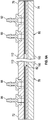
- Figs. 14A-14C depict a cross-section of a chip 500 having a body 502 that defines a channel 504.
- the channel 504 has a channel ceiling 506 and an opposing channel floor 508.
- a first wave generator 510 is positioned on an upper surface 512 of the chip 500 and a second wave generator 514 is positioned on an opposing lower surface 516 of the chip 500.
- the wave generators 510, 514 are tuned to generate a SAW 518 with a wavelength of 0.5 ⁇ .
- the nodes shown as filled-in circles, would push flowing cells toward the antinode, shown as an open circle.
- the wave generators 510, 514 are tuned to generate a SAW 520 with a wavelength of 1.5 ⁇ having two nodes and one antinode positioned in the channel 504.
- cells flowing through the channel 504 would be pushed away from the nodes towards the antinode in the center of the channel 504 and towards the antinodes within the chip body 502. Therefore, if it is desired to direct cells toward the antinode in the center of the channel 504, either a new chip can be manufactured with a channel having a different size or the current channel 504 can be modified.
- the frequency of the wave generator(s) can vary, for example ranging from about 100 kHz to about 2000 kHz.
- the specific frequency may be determined in conjunction with the dimensions of the channel or other reservoir in which the standing wave is to be created, so as to produce pressure nodes in the desired locations.
- the position of a pressure node or antinode associated with a SAW in a chip is dependent on the thickness of the chip materials in between the wave generators (or between a wave generator and a reflective surface) and the speed of sound in the chip material.
- the fluid reservoir (channel) dimensions are preferably optimized in regard to the frequency of the wave generator. For example, whereas low frequencies can support large channel dimensions, high frequencies are typically used with small channel dimensions.
- the chips of the present technology comprise channels having a cross-sectional aspect ratio (width:height) of from about 1:1 to about 50:1 or from about 1:1 to about 40:1, or from about 1:1 to about 30:1, or from about 1:1 to about 20:1, or from about 1:1 to about 10:1, or from about 1:1 to about 5:1.
- the input voltage of the wave generators can be from about 1 V to about 120 V and is dependent on chip geometry, hematocrit, and flow rate.
- the wave propagating devices are disposed on the surface of the device reservoir, so as to be in acoustic communication with the multicomponent fluid in the reservoir.
- the wave propagating devices may be disposed at any point laterally along a surface of the channel, parallel to the axis of fluid flow.
- a first wave generator and a second fluid propagating component may be essentially in the mid-point of the channel, between the inlet and outlet.
- the wave generator and second fluid propagating component are disposed near the outlet of the channel.
- cells in the multicomponent fluid may be disposed in the fluid more easily and using less power than in embodiments where the wave propagating components are disposed at or near the mid-point of the channel.
- the precise special orientation of a wave propagating component near the outlet of the channel will be affected by the length of the channel (i.e, in the dimension parallel to the fluid flow) and the size of the wave propagating component.
- the mid-point of the wave propagating component is within 10%, within 20%, or within 30% of the outlet, as a percentage of the distance between the inlet and outlet.
- a wave propagating component 628 comprises a central power generating region, defined by a first end point 650 and a second end point 651 on the longitudinal surface (e.g., top surface 606) of the chip 602.
- the length of the central power generating region i.e., the distance 652 between the first end point 651 and the second end point 652, consists of the middle 20%, 10% or 5% of the wave propagating component, as a percentage of the overall length 653 of the wave propagating component (i.e., the dimension that is parallel to the flow of fluid in the channel).
- a point within the central power generating region of the wave propagating component is axially aligned with the outlet end (second end, as discussed above) of the separation channel. That is, in reference to Fig. 15 , both a point that is within the central power generating region of the wave propagating component, and the outlet end 622 of the separation channel 616, fall on a common axis 632 that is orthogonal to a surface (e.g., ceiling 618) of the channel.
- the second end point 651 of the central power generating region is axially aligned with the outlet end 622 of the separation channel 616.
- the present technology provides devices, such as fluidic chips, that comprise a channel or other reservoir in which standing acoustic waves may be used so as to apply forces to cell in a multicomponent fluid.
- forces may be used to move the cells in the fluid, such as by forcing cells from the fluid into a second fluid within the device.
- movement of cells from a first multicomponent fluid effects washing of the cells, thereby creating a suspension of cells in a second fluid
- the chips may be constructed of any of a variety of materials, including such materials known in the art.
- the materials are preferably compatible with physiological materials (e.g., blood cells) that are processed with the devices, and have appropriate acoustic characteristics.
- physiological materials e.g., blood cells
- PTT polyethylene terephthalate
- PMMA poly(methyl methacrylate)
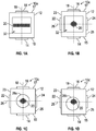
- Fig. 1A shows a cross-sectional view of an exemplary device 10a comprising a substrate or device body 12, a first wave component 14, and a second wave component 16 positioned on opposite sides 15, 17 of the body 12, wherein the body 12 defines a channel 32 with a square cross-sectional geometry.
- the first wave component 14 and the second wave propagating component 16 are individually either a wave generator or a reflective material or reflective surface or layer.
- the other wave component 14, 16 is a wave generator.
- a side 15, 17 of the device body 12 can be composed of a reflective material so long as the opposite side 15, 17 comprises a wave generator.
- a SAW is generated between the first wave component 14 and the second wave component 16 along line 18.
- a pressure node associated with the SAW which is located within the channel 32, forces a plurality of cells 20 into a plane perpendicular to the line 18.
- Fig. 1B shows a cross-sectional view of another exemplary device 10b, which is similar to device 10a.
- the device 10b further comprises a third wave propagating component 22 and a fourth wave propagating component 24 positioned on opposite sides 23, 25 of the body 12.
- the third wave component 22 and the fourth wave component 24 are individually either a wave generator or a reflective material or reflective surface or layer.
- the other wave component 22, 24 is a wave generator.
- the third wave component 22 and the fourth wave component 24 are positioned orthogonal to the first wave component 14 and the second wave component 16 on sides 23, 25 of the body 12.
- a first SAW is generated between the first wave component 14 and the second wave component 16 along line 18 and a second SAW is generated between the third wave component 22 and the fourth wave component 24 along line 26 that is orthogonal to the fist line 18, such that the second SAW is orthogonal to the first SAW.
- Pressure nodes associated with the SAWs interest with each other and interact with the plurality of cells 20 in orthogonal directions to force the cells 20 into a linear configuration, as shown more clearly in Fig. 3 .
- Fig. 2 provides a perspective view of a device 30a, which is similar to the device 10a.
- the device 30a comprises a substrate or device body 12, a first wave component 14, and a second wave component 16 positioned on opposing sides 15, 17 of the body 12.
- the first and second wave components 14, 16 are wave generators.
- the device 30a comprises a longitudinal channel 32 with a square cross-sectional geometry that extends along a longitudinal axis 33.
- the cells 20 are suspended in a plane that extends along the axis 33 and that is parallel to the wave components 14, 16 by a pressure node associated with a SAW generated by the first wave component 14 and the second wave component 16.
- Fig. 3 provides a perspective view of another exemplary device 30b, which is similar to the device 10b.
- the device 30b comprises a substrate or device body 12, a first wave component 14 and a second wave component 16 positioned on opposing sides 15, 17 of the body 12, and a third wave component 22 and a fourth wave component 24 positioned on opposing sides 23, 25 of the body 12 that are orthogonal to the sides 15, 17 that include the first and second wave components 14, 17.
- the device 30b comprises a longitudinal channel 32 with a square cross-sectional geometry that extends along the axis 33. As shown in Fig.
- the cells 20 are suspended in a cylindrical line along the axis 33 of the channel 32 by a first pressure node associated with a first SAW generated by the first wave component 14 and the second wave component 16 and by a second pressure node associated with a second SAW generated by the third wave component 22 and the fourth wave component 24, wherein the second SAW is orthogonal to the first SAW.
- a device 10c is shown, which is similar to device 10b. However, device 10c further comprises a channel 28a with a circular cross-sectional shape. Because the channel 28a is centered in the substrate 12, and because the wave components 14, 16, 22, 24 are centered on their respective sides of the substrate 12, the cells 20 are suspended in a line central to the channel 28a. As shown in Fig. ID, a device 10d comprises a channel 28b, which is offset relative to the center of the substrate 12. The cells 20 are positioned in a line extending along a midpoint of a cross-section of the substrate 12 because the pressure nodes force the cells 20 to that position. In other words, the cells 20 are positioned based upon the pressure node or nodes and not upon the positioning of the channel 28a, 28b, 32.
- the device comprises a phantom material.
- a "phantom material” is a material that mimics the acoustic properties of the fluid through which acoustic waves are propagated.
- the phantom material mimics the acoustic properties of water with a low attention coefficient. Therefore, an acoustic wave travels through phantom materials substantially as it would, such as with the same speed, through water. For example, sound travels through water at a rate of from about 1450 m/s to about 1570 m/s.
- phantom materials travels through the phantom materials at a rate of from about 1200 m/s to about 1600 m/s, or at a rate of from about 1400 m/s to about 1500 m/s.
- suitable phantom materials include Solid Water® phantom material from CNMC Co. Inc. (Nashville, TN), Virtual WaterTM phantom material from CNMC Co. Inc., and Plastic Water® phantom material from Computerized Imaging Reference Systems, Inc. (Norfolk, VA).
- Various plastics, acrylics, and glasses detrimentally affect how acoustic waves travel.
- phantom materials do not affect how an acoustic wave travels, separation devices with complex geometries, such as single chips or devices having multiple channels, can be generated. Therefore, phantom materials may be included in channels to alter a flow path without affecting the position of an acoustic node or antinode. Additionally, in some embodiments, two or moredevices of the current technology may be multiplexed to reduce surface area and to increase efficiency.
- the devices 10a, 10b, 10c, 10d shown in Figs. 1A-1D comprise, at least partially, a phantom material.
- Fig. 14C depicts a device having channels comprising a phantom material.
- the channel 504 may comprise a first sheet of phantom material 522 along the ceiling 506 of the channel 504 and a second sheet of phantom material 524 along the floor 508 of the channel 504.
- the SAW 520 travels through phantom materials substantially as it would, such as with the same speed, through water. Therefore, placement of the sheets of phantom material 522, 524 does not affect the location of the nodes and antinodes.
- nodes can be located at interfaces between the sheets of phantom materials 522, 524 and the channel 504 so that the nodes force cells only towards the antinode in the center of the channel 504.
- phantom materials can be used to manipulate the dimensions of the channel 504 without affecting the location of the nodes generated by the SAW 520. Further exemplary chip and separation embodiments are provided below.
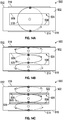
- Fig. 4 shows a cross-section view of another exemplary device 40 for washing a multicomponent mixture comprising cells, such as, for example, red blood cells.
- the device 40 comprises a body 42 defining a channel 44, a first wave component 46 positioned on or near a first side 47 of the body 42 and a second wave component 48 positioned opposite to the first wave component 46 on or near a second opposing side 49 of the body 42.
- the first wave component 46 and the second wave component 48 are individually either a wave generator or a reflective material or reflective surface or layer. However, when one of the wave components 46, 48 is a reflective material or reflective surface or layer, the other wave component 46, 48 is a wave generator.
- a SAW is generated between the first wave component 46 and the second wave component 48 such that a pressure node is located within the channel 44.
- the channel 44 comprises a first horizontal section 50, a second connecting section 52, and a third horizontal section 54, such that the first horizontal section 50 is offset from the second horizontal section 54.
- the third section 52 is bifurcated into a first collection channel 56 and a second collection channel 58 by a planar shelf 60 defined by the body 42.
- the wave components 46, 48 are positioned on the first side 47 and on the second opposing side 49 of the body 42, respectively, which are parallel to the channel 44 at the connecting section 52 and the second horizontal section 54, such that the channel 44 is positioned between the first and second wave components 46, 48.
- the wave propagating components 46, 48 are positioned close to the collection channel 58 to promote efficient separation.
- a multicomponent mixture comprising red blood cells 62 and a wash material 64 are introduced into the device 40, they mix at the first lower horizontal section 50.
- the red blood cells 62 are forced into a plane at the connecting section 52 corresponding to a pressure antinode.
- the wash material flow thereof represented by arrows 64, passes through the red blood cells 62, thereby washing the red blood cells 62.
- the red blood cells 62 are then collected from the second collection channel 58 and the wash material 64 and other waste is collected from the first collection channel 56.
- the multicomponent mixture comprising red blood cells 62 and the wash material 62 are mixed prior to being introduced into the device 40.
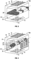
- Fig. 5 depicts another exemplary device a device 70 for washing a multicomponent mixture.
- the device 70 comprises a body 72 having a first surface 74, a second opposing surface 76, a first end region 78, and a second end region 80.
- the body 72 defines a channel 82 extending along a longitudinal axis 84 from the first end region 78 to the second end region 80.
- the device 70 further comprises a first inlet 86, a second inlet 88, a first outlet 90, and a second outlet 92, all in fluid communication with the channel 82.
- Fig. 6A is an exploded, cross-sectional perspective of the device 70 taken along line 6A of Fig.
- the channel 82 is bifurcated at the first end region 78 by a first planar shelf 94 defined by the body 72, which keeps components that are introduced into the device 70 through the inlets 86, 88 separate. However, in some embodiments (not shown) there is only one inlet and no shelf to separate components. Also, the channel 82 is bifurcated at the second end region 80 by a second planar shelf 96 defined by the body 72, which keeps the components separated for collection through the outlets 90, 92 by way of a first collection channel 97 and a second collection channel 99, respectively.
- the channel 82 of the device 70 includes a receiving or mixing region 98 near the first end region 78, a collection region 102 near the second end region 80, and a separation region 100 there between. Additionally, the channel 82 comprises a channel floor 104, two side walls 106 that extend longitudinally along the axis 84, and a channel ceiling 108. In various embodiments, the channel floor 104 and sides 106 are composed of a phantom material as described above. In various embodiments, at least the separation region 100 of the channel 82 has a rectangular cross-sectional geometry. Additionally, the separation region 100 of the channel 82 has a length L, a width W, and a height H that results in passing a large volume through the device.
- the channel 82 can have a cross-sectional aspect ratio (W:H) of from about 1:1 to about 50:1.
- W:H cross-sectional aspect ratio
- the length L is greater than about 20 mm or greater than about 100 mm. In other embodiments, the length L is from about 10 mm to about 100 mm, or from about 25 mm to about 75 mm.
- the length L is about 10 mm, about 15 mm, about 20 mm, about 25 mm, about 30 mm, about 35 mm, about 40 mm, about 45 mm, about 50 mm, about 55 mm, about 60 mm, about 65 mm, about 70 mm, about 75 mm, about 80 mm, about 85 mm, about 90 mm, about 95 mm, or about 100 mm.
- the width W is greater than about 5 mm, or greater than about 50 mm. In other embodiments, the width W is from about 5 mm to about 50 mm, or from about 20 mm to about 40 mm.
- the width W is about 5 mm, about 10 mm, about 15 mm, about 20 mm, about 25 mm, about 30 mm, about 35 mm, about 40 mm, about 45 mm, or about 50 mm.
- the height H is greater than about 0.5 mm, or greater than about 3 mm. In other embodiments, the height H is from about 0.5 mm to about 3 mm. In yet other embodiments, the height H is about 0.5 mm, about 1 mm, about 1.5 mm, about 2 mm, about 2.5 mm, or about 3 mm.
- the dimensions of the channel 82 allow for a high throughput of a mixture to be washed.
- the device 70 can process blood compositions, mixtures, or suspensions at a rate of about 10 mL/min to about 30 mL/min, or at a rate from about 20 mL/min to about 25 mL/min. In one embodiment, the device 70 processes blood compositions, mixtures, or suspensions at a rate of about 22.5 mL/min. Accordingly, a unit of blood, having a volume of from about 400 mL to about 500 mL, combined with from about 0.5 L to about 3 L of wash solution can be processed in from about 30 min to about 350 min. In one embodiment, the device 70 can process a volume of 450 mL in about 20 min. However, the device 70 can accommodate and process a volume of from about 1 mL to about 20 L, wherein about 20 L can be processed in about 12 hrs, in about 13 hrs, or in about 14 hrs.
- the device 70 comprises a first wave component 110 positioned adjacent and parallel to the channel 82 and a second wave component 112 positioned adjacent and parallel to the channel 82, such that the channel 82 is positioned between the first and second wave components 110, 112.
- the separating region 100 of the channel 82 is positioned between the first and second wave components 110, 112.
- the first wave component 110 and the second wave component 112 are individually either a wave generator or a reflective material or reflective surface or layer. However, when one of the wave components 110, 112 is a reflective material or reflective surface or layer, the other wave component 110, 112 is a wave generator.
- the reflective surface can be the second surface 76 of the device 70, or it can be a reflective film, sheet, slide, or membrane coupled to the second surface 76.
- the first wave component 110 is an electrical contact that couples to a wave generator on a base unit. Therefore, when the first wave component 110 is a wave generator or an electrical contact, the second wave component 112 is either a second wave generator or a reflective surface or layer or material.
- a SAW is generated between the first wave component 110 and the second wave component 112, whereby a pressure node 114 (see Fig. 7B ) associated with the SAW is located within the separation region 100 of the channel 82.
- the SAW is generated from the wave components 86, 88 operating at a low frequency range of from about 300 kHz to about 1000 kHz, or from about 400 kHz to about 600 kHz, or from about 450 kHz to about 500 kHz, in order to isolate components from a multicomponent mixture in the channel 62 with such a large volume. Even though this low frequency range results in a low pressure gradient, surprisingly, component isolation is achieved. In other embodiments, not shown in Fig.
- the device 70 further comprises third and fourth wave components as or on opposing sides of the device 70 such that the third and fourth wave components generate a second SAW orthogonal to the SAW generated by the first and second wave components 110, 112, wherein the second SAW provides a second pressure node located in the separation region 100 of the channel 82.
- the device 70 can be manufactured by any means known in the art, including, for example, injection molding, compression molding, or 3-dimensional printing (3-D printing).
- the device 70 is manufactured by stacking together a plurality of layers 116a-116h, wherein each layer is bonded to an adjacent layer with an adhesive.
- the layers 116a-116h are composed of any material known in the art.
- Non-limiting examples of materials for the layers 116a-116h include plastics, such as polyethylene terephthalate (PET) acrylics, such as poly(methyl methacrylate) (PMMA), and glasses.
- the layer 116g has two longitudinal protrusions 118 that form the two side walls 106 of the channel 82.
- the layer 116g is composed of a phantom material (as described above) that mimics how acoustic waves travel through water to provide the device 70 with the channel 82 having phantom side walls 106 and a phantom floor 104.
- the first wave component 110 is coupled to a bottom surface 120 of the layer 116g and the layer below it, layer 116h, is optional.
- the first wave component 110 is coupled to a bottom surface 122 of the layer 116h.
- a first layer 116a can either be composed of a reflective material or the second wave component 112 can be coupled to a surface 76 of the layer 116a.
- the first layer 116a can be composed of a phantom material in various embodiments.
- Fig. 7 is a cross-sectional illustration of the device 70 when the device 70 is manufactured by a means other than by stacking together a plurality of layers, such as by injection molding, compression molding, or 3-D printing.
- the components of Fig. 7 are the same as those shown in Figs. 6A and 6B , but the dimensions may be slightly different.
- the device 70 is configured to wash a multicomponent mixture.
- the multicomponent mixture comprises red blood cells 124 or red blood cells 124 and a rejuvenation solution.
- the multicomponent mixture is introduced to the device 70 through a first conduit coupled to an inlet 86, 88.
- a first conduit 128 is coupled to the second inlet 88.
- a wash material 126 is introduced to the device 70 through a second conduit coupled to the inlet 86, 88 that is not coupled to the first conduit 128.
- a second conduit 130 is coupled to the first inlet 86.
- Flow of the multicomponent mixture comprising red blood cells 124 and the wash material 126 can be established, by pumps, such as peristaltic pumps, optionally coupled to pulse dampeners or pulse suppressors.
- pumps such as peristaltic pumps
- pulse dampeners or pulse suppressors Examples of suitable pumps, pulse dampeners, and pulse suppressors that can be used for any embodiments provided herein are described in U.S. Patent Publication No. 2015/0111195, Hamman et al., published on April 23, 2015 .
- the multicomponent mixture comprising red blood cells 124 and the wash material 126 are mixed together at the receiving or mixing region 98 of the channel 82.
- the multicomponent mixture and washing material are combined prior to be introduced into the device 70.
- the device 70 may have a single input, as described above or the multicomponent mixture and wash material can be delivered into the device by either inlet 86, 88 of the device 70.
- the multicomponent mixture comprising red blood cells 124 and the wash material 126 flow through the channel 82, they interact with a pressure node 114, generated by the wave components 110, 112, in the separation region 100 of the channel 82.
- the pressure node 114 is located at or near the channel ceiling 108 and/or the channel floor 104, such that an antinode is positioned at a location to which the red blood cells 124 are directed.
- the wave components 110, 112 are shown positioned in the middle of the first and second surfaces 74, 76 in Figs.
- the wave components 110, 112 are positioned near the outlets 90, 92, such that a strong pressure wave pushes the cells 124 towards the collection channel 99 easier and with less power; rather than aligning the cells 124 the length of the channel 82.
- the pressure node 114 pushes, forces, isolates, or moves a component of the multicomponent mixture, such as the red blood cells 124, adjacent to the shelf 96 and into the second collection channel 99 while the remainder of the multicomponent mixture and wash material 126 flow to the first collection channel 97.
- the shelf 96 is thin and rigid so as to minimize turbulence within the channel 82.
- the component pushed, forced, isolated, or moved to the second collection channel 99 is collected through a third conduit 132 coupled to the second outlet 92 and the remaining materials are collected through a fourth conduit 134 coupled to the first outlet 90.
- chips are designed so have a particular spacial orientation, such as in systems (as described below) in which the devices are placed in a base unit.
- the gravity may have an effect on the flow of materials, such as cellular materials, through the chip.
- the outlet of the chip is oriented lower than the inlet (i.e., at a location at a position lower than the inlet relative to the vertical axis of the chip, it being understood that the inlet and outlet are substantially at opposing ends of the chip relative to the orthogonal horizontal axis of the chip).
- the outlet of the device is oriented higher than inlet.
- Figs. 6B and 7B show red blood cells 124 flowing downward to the second collection channel 99.
- the pressure antinode is located such that the component is forced upward to the first collection channel 97.
- the red blood cells 124 are preferably introduced through the first inlet 86 and the wash material 126 is introduced through the second inlet 88.
- the wash material 126 contacts an upper surface of the flow of red blood cells 124.
- the red blood cells 124 interact with the nodes of a SAW generated between the wave components 110, 112
- the red blood cells 124 are forced upward, against gravity, through the wash material 126 and isolated at the first collection channel 97 as washed red blood cells 124.
- the isolated and washed red blood cells are then collected through the first outlet 90 and the remaining materials are collected through the second outlet 92.
- Another example of such an embodiment, where cells are forced upward against gravity by a node of a SAW is shown in Fig. 12 , which is described in more detail below.
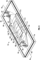
- the present technology provides another device 150 for washing a multicomponent mixture.
- the device 150 comprises a body 152 having a first surface 154, a second opposing surface 156, a first end region 158, and a second end region 160.
- the body 152 defines a channel 162 extending along a longitudinal axis 163 from the first end region 158 to the second end region 160.
- the device 150 further comprises a first pair of inlets 164, a second pair of inlets 166, a first pair of outlets 168, and a second pair of outlets 170, all in fluid communication with the channel 162.
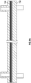
- Fig. 10 is an exploded cross-sectional perspective of the device 150 taken along line 9A of Fig.
- the channel 162 is trifurcated at the first end region 158 by a first shelf 181 defined by the body 152 and a second shelf 182 defined by the body 152, which keeps components that are introduced into the device 150 through the pairs of inlets 164, 166 separate.
- the channel 162 is trifurcated at the second end region 160 into a first collection channel 187, a second collection channel 189, and a third collection channel 191 by a third shelf 183 defined by the body 152 and fourth shelf 184 defined by the body 152, wherein the first collection channel 187 is located between the second surface 156 and the third shelf 183, the second collection 189 channel is located between the third and fourth shelves 183, 184, and the third collection channel 191 is located between the fourth shelf 184 and the first surface 154.
- the collection channels 187, 189, 191 keep the components separated for collection through the pairs of outlets 168, 170, such that the second collection channel 189 is in fluid communication with the first pair of outlets 168 and the first and third collection channels 187, 191 are in fluid communication with the second pair of outlets 170.
- the channel 162 of the device 150 includes a receiving or mixing region 172 near the first end region 158, a collection region 176 near the second end region 160, and a separation region 174 there between. Additionally, the channel comprises a channel floor 178, two side walls 180 that extend longitudinally along the axis 163, and a channel ceiling 179. In various embodiments, the channel floor 178 and sides 180 are composed of a phantom material as described above. In various embodiments, at least the separation region 174 of the channel 162 has a rectangular cross-sectional geometry. Additionally, the separation region 174 of the channel 162 has a length L', a width W', and a height H' that results in passing a large volume through the device 150.
- the channel 162 can have a cross-sectional aspect ratio (W':H') of from about 1:1 to about 50:1.
- W':H' cross-sectional aspect ratio
- the length L' is greater than about 20 mm or greater than about 100 mm. In other embodiments, the length L' is from about 10 mm to about 100 mm, or from about 25 mm to about 75 mm.
- the length L' is about 10 mm, about 15 mm, about 20 mm, about 25 mm, about 30 mm, about 35 mm, about 40 mm, about 45 mm, about 50 mm, about 55 mm, about 60 mm, about 65 mm, about 70 mm, about 75 mm, about 80 mm, about 85 mm, about 90 mm, about 95 mm, or about 100 mm.
- the width W' is greater than about 5 mm, or greater than about 50 mm. In other embodiments, the width W' is from about 5 mm to about 50 mm, or from about 20 mm to about 40 mm.
- the width W' is about 5 mm, about 10 mm, about 15 mm, about 20 mm, about 25 mm, about 30 mm, about 35 mm, about 40 mm, about 45 mm, or about 50 mm.
- the height HP is greater than about 0.5 mm, or greater than about 3 mm.
- the height H' is from about 0.5 mm to about 3 mm.
- the height H' is about 0.5 mm, about 1 mm, about 1.5 mm, about 2 mm, about 2.5 mm, or about 3 mm.
- the dimensions of the channel 62 allow for a high throughput of a mixture to be washed.
- the device 150 can process blood compositions, mixtures, or suspensions at a rate of about 10 mL/min to about 30 mL/min, or at a rate from about 20 mL/min to about 25 mL/min. In one embodiment, the device 150 processes blood compositions, mixtures, or suspensions at a rate of about 22.5 mL/min. Accordingly, a unit of blood, having a volume of from about 400 mL to about 500 mL, combined with from about 0.5 L to about 3 L of wash solution can be processed in from about 30 min to about 350 min. In one embodiment, the device 150 can process a volume of 450 mL in about 20 min. However, the device 150 can accommodate and process a volume of from about 1 mL to about 20 L, wherein about 20 L can be processed in about 12 hrs, in about 13 hrs, or in about 14 hrs.
- the device 150 comprises a first wave component 186 positioned adjacent to the channel 162 on or near the first side 154 of the device 150 and a second wave component 188 positioned adjacent to the channel 162 on or near the second side 156 of the device 150 such that the channel 162 is positioned between the first and second wave components 186, 188.
- the separation region 174 of the channel 162 is positioned between the first and second wave components 186, 188.
- the first wave component 186 and the second wave component 188 are individually either a wave generator or a reflective material or reflective surface. However, when one of the wave components 186, 188 is a reflective material or reflective surface, the other wave component 186, 188 is a wave generator.
- At least one of the wave components 186, 188 is a wave generator.
- the reflective surface can be the second surface 156 of the device 150, or it can be a reflective film, sheet, slide, or membrane.
- the first wave component 186 is an electrical contact that couples to a wave generator on a base unit. Therefore, when the first wave component 186 is a wave generator or an electrical contact, the second wave component 188 is either a second wave generator or a reflective surface or material.
- a SAW is generated between the first wave component 186 and the second wave component 188, whereby a pressure node 196 (see Fig.
- the SAW is generated from the wave components 186, 188 operating at a low frequency range of from about 300 kHz to about 1000 kHz, or from about 400 kHz to about 600 kHz, or from about 450 kHz to about 500 kHz, in order to isolate components from a multicomponent mixture in the channel 162 with such a large volume. Even though this low frequency range results in a low pressure gradient, surprisingly, component isolation is achieved. In other embodiments, not shown in Fig.
- the device 150 further comprises third and fourth wave components as or on opposing sides of the device 150 such that the third and fourth wave components generate a second SAW orthogonal to the SAW generated by the first and second wave components 186, 188, wherein the second SAW provides a second pressure node located in the separation region 174 of the channel 162.
- the device 150 can be manufactured by any means known in the art, including, for example, injection molding, compression molding, or 3-dimensional printing (3-D printing).
- the device 150 is manufactured by stacking together a plurality of layers 190a-1901, wherein each layer is bonded to an adjacent layer with an adhesive.
- the layers 190a-1901 are composed of any material known in the art.
- Non-limiting examples of materials for the layers 190a-1901 include plastics, such as polyethylene terephthalate (PET) acrylics, such as poly(methyl methacrylate) (PMMA), and glasses.
- an optional layer equivalent to layer 90g of Fig. 7 is positioned between layer 190k and 1901 and has two longitudinal protrusions that form the two side walls 180 of the channel 162.
- the optional layer is composed of a phantom material that mimics how acoustic waves travel through water to results in the device 150 with the channel 162 having phantom side walls 180 and a phantom floor 178.
- the first wave component 186 is coupled to a bottom surface of the optional layer.
- the first wave component 186 is coupled to a bottom surface 198 of the layer 1901.
- layer 1901 is composed of a phantom material and comprises two longitudinal protrusions that form the two side walls 180 of the channel 162.
- the first wave component 186 is coupled to the bottom surface 198 of the layer 1901.
- a first layer 190a can either be composed of a reflective material or the second wave component 188 can be coupled to the second surface 156 of the layer 190a.
- the first layer 190a is composed of a phantom material in various embodiments.
- Fig. 10 is a cross-sectional illustration of the device 150 when the device 150 is manufactured by a means other than by stacking together a plurality of layers, such as by injection molding, compression molding, or 3-D printing.
- the components of Fig. 10 are the same as those shown in Figs. 9A and 9B , but the dimensions may be slightly different.
- the device 150 is configured to wash a multicomponent mixture.
- the multicomponent mixture comprises red blood cells 210 or red blood cells 210 and a rejuvenation solution.
- the multicomponent mixture comprising red blood cells 210 is introduced to the device 150 through a pair of first conduits coupled to the pair of second inlets 166.
- a wash material 212 is introduced to the device 150 through a pair of second conduits coupled to the pair of first inlets 164.
- Flow of the multicomponent mixture 210 and the wash material 212 can be established, by pumps, such as peristaltic pumps, optionally coupled to pulse dampeners or pulse suppressors, as described above.
- the multicomponent mixture 210 and the wash material 212 are mixed together at the receiving or mixing region 172 of the channel 162.
- the multicomponent mixture comprising red blood cells 210 and the washing material 212 are combined prior to be introduced into the device 150 to generate a pre-mixed composition.
- the device 150 may have a single input, as described above, or the pre-mixed composition can be delivered into the device 150 by any inlet or combination of inlets 164, 166. Referring again to Figs.
- the pressure node 196 is located at or near the channel ceiling 179 and/or the channel floor 178, such that an antinode is positioned at a location to which the red blood cells 210 are directed.
- the wave components 186, 188 are shown positioned in the middle of the first and second surfaces 154, 156 in Figs.
- the centers of the wave components 186, 188 are positioned near to the outlets 168, 170, such that a strong pressure wave pushes the cells 210 towards the collection channel 189 easier and with less power; rather than aligning the cells 210 the length of the channel 162.
- the pressure node 196 pushes, forces, isolates, or moves a component of the multicomponent mixture, such as red blood cells, between the third and fourth shelves 183, 184 and into the second collection channel 189 while the remainder of the multicomponent mixture and wash material flow into the first and third collection channels 187, 191.
- the third and fourth shelves 183, 184 are thin and rigid so as to minimize turbulence within the channel 162.
- the component pushed, forced, isolated, or moved into the second collection channel 180 is collected through a third pair of conduits coupled to the first pair of outlets 168 and the remaining materials are collected through a fourth pair of conduits coupled to the second pair of outlets 170.
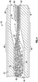
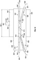
- the present technology provides another device 600 for washing a multicomponent mixture.
- the device 600 comprises a separation chip 602 having a body 604.
- the body 604 has a top surface 606 and an opposing bottom surface 608. Additionally, the body 604 defines an upper inlet channel 610 and a lower inlet channel 612 that merge into a first end 614 of a separation channel 616 due to an incline path of the lower inlet channel 612.
- the separation channel 616 has a channel ceiling 618 and a channel floor 620.
- the separation channel 616 bifurcates at a second end 622 into an upper outlet channel 624 and a lower outlet channel 626, wherein the lower outlet channel 626 has a declined path relative to the separation channel 616.
- a first wave component 628 is positioned on the top surface 606 of the chip 602 and a second wave component 630 is positioned on the bottom surface 608 of the chip 602.
- the first wave component 628 and the second wave component 630 are individually either a wave generator or a reflective material or reflective surface or layer. However, when one of the wave components 628, 630 is a reflective material or reflective surface or layer, the other wave component 628, 630 is a wave generator.
- the first and second wave components 628, 630 have a center or central region represented by a dotted line axis 632.
- the wave components 628, 630 are positioned on the respective surfaces 606, 608 of the chip 602 such that their center or central power generating region, defined by a first end point 650 and a second end point 651, is aligned with the second end 622 of the separation channel 616 prior to the separation channel's 616 bifurcation into the upper and lower outlet channels 624, 626.
- this alignment can result in high separation efficiency because a resulting SAW is strongest in a region between the center regions of the wave components 628, 630 and because cells do not have to be suspended throughout the whole length of the separation channel 616 as discussed further below.
- the wave components 628, 630 are positioned relative to other sections of the separation channel 616, with the proviso that the separation channel 616 is positioned between the first and second wave components 628, 630.
- the device 600 is configured to wash a multicomponent mixture comprising cells 634.
- the multicomponent mixture comprises red blood cells or red blood cells and a rejuvenation solution.
- the multicomponent mixture comprising red blood cells 634 is introduced to the device 600 through a lower inlet port 636 that is in fluid communication with the lower inlet channel 612.
- a wash material 638 is introduced to the device 600 through an upper inlet port 640 that is in fluid communication with the upper inlet channel 610.
- Flow of the multicomponent mixture 634 and the wash material 638 can be established, by pumps, such as peristaltic pumps, optionally coupled to pulse dampeners or pulse suppressors, as described above.
- the multicomponent mixture 634 and the wash material 638 merge at the separation channel, the multicomponent mixture 634 flows adjacent to the channel floor 620 and the wash material 638 flows adjacent to the channel ceiling 618. As such, the wash material 638 flows over the multicomponent mixture 634 to create an interface between the wash material 638 and the multicomponent mixture 634. There is little or no mixing between the wash material 638 and the multicomponent mixture 640 near the first end 614 of the separation channel.
- the first and second wave components 628, 630 generate a SAW with an antinode positioned near the upper outlet channel 624.
- Red blood cells 634 that are washed and clean can be collected at an upper outlet port 642 that is in fluid communication with the upper outlet channel 624 and remaining wash material 638 along with other components, such as, for example, rejuvenation solution, can be collected at a lower outlet port 644 that is in fluid communication with the lower outlet channel 626.
- the present technology provides systems for separating of cells from a multicomponent fluid, comprising a device of the present technology (as described above) and a base unit that facilitates the function of the device.
- the device is a disposable chip, operable for a limited number of uses (e.g., a single use).
- the base unit comprises components that are operable for multiple uses.
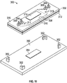
- FIG. 11 An exemplary system 300 is shown in Fig. 11 .
- the system comprises a disposable separation device 302 and base unit 350.
- Any separation device described herein, including the device 70 of Fig. 5 and the device 150 of Fig. 8 can be used as the separation device 302.
- the separation device 302 comprises inlets 304, outlets 306, a channel 308, an optional first wave component 310 coupled to a first surface 312, and a second wave component 314 coupled to a second opposing surface 316, wherein the inlets 304 are in fluid communication with a first end of the channel 317 and the outlets 306 are in fluid communication with a second end of the channel 319.
- the optional first wave component 310 can be a wave generator.
- the second wave component 314 can be a wave generator or a reflective material or surface or layer.
- the base unit 350 comprises at least one of a plurality of coupling members 352 and a third wave component 354.
- the coupling members can be any coupling members known in the art.
- Non-limiting examples of connecting members include snaps, clips, clasps, screws, adhesives, fasteners, etc.
- the third wave component 354 is either a wave generator or an electrical contact.
- the first wave component 310 of the disposable separation device 302 is a wave generator
- the third wave component 354 is an electrical contact.
- the disposable separation device 302 comprises a first wave component 310, which is a wave generator.
- the third wave component 354 of the base unit 350 is an electrical contact.
- the coupling members 352 are then configured to couple and hold the disposable separation device 302 to the base unit 350 such that the wave generator of the disposable separation device 302 contacts and communicates with the electrical contact.
- the disposable device 302 does not comprise a first wave component 310.
- the third wave component 354 of the base unit 350 is a wave generator.
- the snaps 352 are then configured to snap the disposable separation device 302 to the base unit 350 such that the separation channel 308 is positioned between the wave generator on the base unit 350 and the second wave component 314 of the disposable separation device 302. Nonetheless, in all embodiments a SAW is generated in the disposable separation device 302 with power provided by the base unit 350.
- the disposable separation device 302 can be prepackaged and sterilized. When ready for use, the disposable separation device 302 is removed from the packaging and snapped onto the base unit 350. A wash material is then pumped through the device and the base unit is activated to generate an SAW. A multicomponent mixture, such as a red blood cell composition, is then pumped through the separation device 302, wherein the blood is washed and separated from undesired components.
- the target component may be red blood cells or other cells.
- the multicomponent fluid comprises a physiologically-acceptable carrier for the target component, such as saline or plasma.
- Methods include those comprising separating the red blood cells from one more second components of the multicomponent fluid.
- the second component comprises at least a portion of the carrier; in some embodiments, the second component comprises essentially all of the carrier. The second component may be used in other processes, or may be discarded.
- the target material is red blood cells
- the second component comprises cells and cell debris, such as white blood cells, platelets, dead cells, or cell debris.
- the present technology provides methods for washing red blood cells that have been suspended in a storage solution or other carrier that is not suitable for administration to a human or other animal in a transfusion.
- the red blood cells are substantially removed from storage solution, and resuspended in a wash solution in a device of the present technology.
- red blood cells are often rejuvenated with a rejuvenation or enhancement solution, such as Rejuvesol® red blood cell processing solution commercialized by Citra Labs, LLC (Braintree, MA).
- a rejuvenation or enhancement solution such as Rejuvesol® red blood cell processing solution commercialized by Citra Labs, LLC (Braintree, MA).
- Rejuvesol® red blood cell processing solution commercialized by Citra Labs, LLC (Braintree, MA.
- Such enhancement solutions and methods of use are described in U.S. Patent No. 9,066,909, Alan Gray, issued June 30, 2015 ; U.S. Patent Publication No. 2014/0212400, Alan Gray published July 31, 2014 , and U.S. Patent Publication No. 2014/0212397, Alan Gray et al., published July 31, 2014 .
- the red blood cells are washed with a wash solution, such as water, saline, dextrose, saline with 5% dextrose, phosphate buffered saline, and other wash liquids to remove excess rejuvenation solution from the red blood cells. Therefore, the rejuvenation solution and/or the wash solution need to be removed from the red blood cells prior to transfusion.
- a wash solution such as water, saline, dextrose, saline with 5% dextrose, phosphate buffered saline, and other wash liquids to remove excess rejuvenation solution from the red blood cells. Therefore, the rejuvenation solution and/or the wash solution need to be removed from the red blood cells prior to transfusion.
- methods for washing a multicomponent fluid comprising cells comprises delivering, such as by pumping or flowing, a composition comprising cells and a wash material into a separation device comprising a separation channel having a receiving or mixing region, a separation region and a collection region.
- the composition comprising cells is a composition comprising red blood cells.
- the composition may also comprise materials to be washed away from the cells, including other cell types, dead cells, cell debris, rejuvenation solution, or combinations thereof.
- the wash material is selected from the group consisting of water, saline, dextrose, saline with 5% dextrose, and phosphate buffered saline.
- the separation device can be any separation device described above.
- the method also comprises mixing the composition comprising cells with the wash material. Mixing occurs when the composition comprising cells contacts the wash material in the receiving or mixing region of the channel.
- the composition comprising cells can be mixed with the wash material outside of the device to generate a pre-mixed composition.
- the pre-mixed composition is delivered into the separation device.
- the method comprises isolating or separating a component from the composition comprising cells.
- the component can be a desired type of cell, such as, for example, red blood cells.
- Isolating or separating a component comprises passing, such as by pumping or flowing, the composition comprising cells and the wash material relative to a pressure node generated by a SAW, wherein a pressure node associated with the SAW is located within the separation region of the channel.
- the SAW is generated by wave components operating at a frequency range of from about 300 kHz to about 1000 kHz, or from about 680 kHz to about 710 kHz.
- the method comprises collecting the component at an outlet of the device that is in fluid communication with the collection region of the channel.
- the composition comprising cells is a composition comprising red blood cells
- the red blood cells can be washed and isolated by this method, and then transfused into a human or non-human subject in need thereof.
- FIG. 12 An exemplary embodiment of the present technology is depicted in Figure 12 .
- a wash material liquid stream 401 is introduced in the mixing region or chamber 405 of a device 400 that is operable to separate a component from a multi-component solution using standing acoustic waves, such as described above.
- Such devices and methods are also described in U.S. Patent Application Serial No. 14/519,284, Leach et al., filed October 21, 2014 , and U.S. Provisional Patent Application Serial No. 62/095,480, Abeskaron, filed December 22, 2014 .
- a cellular component liquid stream 402 such as comprising red blood cells (RBC) is introduced into the region 405, in contact with the wash material liquid stream.
- RBC red blood cells
- Application of acoustic waves causes the red blood cells to be moved to the wash material stream, forming a washed component liquid stream 403.
- the cellular component liquid stream 402 is introduced to the mixing region 405 below the wash material liquid stream 401, the relative orientation of the streams may be varied, e.g., such that the cellular component liquid stream 402 may be introduced above the wash material liquid stream 401.
- the interfacial tension between the cellular component liquid stream and the wash material liquid stream is near zero.
- the interfacial tension may be controlled by selection of the components of the respective streams.
- one or both of the density and viscosity of the streams may be adjusted by inclusion of an interfacial adjustment material is preferably biocompatible materials suitable for intravenous administration to a human or animal subject.
- the wash material liquid may comprise dextrose, sucrose or hydrophilic polysaccharide polymers (e.g., dextran and Ficoll) so as to effect a desired density or viscosity.
- the wash material liquid comprises salt, and is isotonic with the cellular component, so as to avoid damage to the cells (e.g., through osmotic shock).
- the wash material liquid comprises sucrose.
- the wash material may be an isotonic mixture of saline and sucrose, having a sucrose concentration of about 9.25%.
- Input offset voltage is a parameter that define a differential DC voltage required between inputs of an amplifier, such as an operational amplifier (op-amp), to make the output zero (for voltage amplifiers, 0 V with respect to ground or between differential outputs, depending on the output type).
- phase shift or phase offset When an input offset voltage is applied, the band of particles flowing through a channel is tighter, i.e., thinner, relative to the standard band shown in Fig. 13A .
- Another parameter that may be adjusted is phase shift or phase offset. This parameter creates a change in the initiation point of a waveform. As shown in Fig. 13C , when a phase shift or phase offset is applied, the band of particles flowing through a channel is tighter, i.e., thinner, relative to the standard band shown in Fig. 13A .
- a user may employ a dithered or swept signal. This process generates a signal for several given frequencies over a given time interval. As shown in Fig.
- the words “prefer” or “preferable” refer to embodiments of the technology that afford certain benefits, under certain circumstances. However, other embodiments may also be preferred, under the same or other circumstances. Furthermore, the recitation of one or more preferred embodiments does not imply that other embodiments are not useful, and is not intended to exclude other embodiments from the scope of the technology.
- the word "include,” and its variants, is intended to be non-limiting, such that recitation of items in a list is not to the exclusion of other like items that may also be useful in the materials, compositions, devices, and methods of this technology.
- the terms “can” and “may” and their variants are intended to be non-limiting, such that recitation that an embodiment can or may comprise certain elements or features does not exclude other embodiments of the present technology that do not contain those elements or features.
- compositions or processes specifically envisions embodiments consisting of, and consisting essentially of, A, B and C, excluding an element D that may be recited in the art, even though element D is not explicitly described as being excluded herein.
- element D is not explicitly described as being excluded herein.
- the term "consisting essentially of' recited materials or components envisions embodiments "consisting of" the recited materials or components.
- A" and “an” as used herein indicate “at least one” of the item is present; a plurality of such items may be present, when possible.
- “About” when applied to values indicates that the calculation or the measurement allows some slight imprecision in the value (with some approach to exactness in the value; approximately or reasonably close to the value; nearly). If, for some reason, the imprecision provided by “about” is not otherwise understood in the art with this ordinary meaning, then “about” as used herein indicates at least variations that may arise from ordinary methods of measuring or using such parameters.
Description
- This application claims the benefit of priority to
U.S. Patent Application No. 62/196,339, filed July 24, 2015 - The present technology relates to separating components, such as red blood cells, from a mixture (such as a suspension), and particularly to separating a selected target component in a high concentration and purity using acoustic waves, such as bulk acoustic waves. Methods for separation of elements from a fluid using standing waves are known, for example, from
WO 2007/128795 . - Blood transfusions are used to treat many disorders and injuries, such as in the treatment of accident victims and during surgical procedures. According to current American Red Cross statistics, about 5 million people receive blood transfusions each year, in the United States, alone. Thus, health care systems rely on the collection and distribution of blood. Typically, blood is obtained from a donor and then processed and stored; units of stored blood or blood products are then taken from storage as needed and transfused into a patient in need. In some cases, the blood may be an autologous donation, where an individual donates blood in expectation of receiving his or her own blood by transfusion during a medical procedure.
- Donated blood is typically processed into components and then placed in storage until needed. When a subject is in need of a blood transfusion, a Unit of blood is commonly removed from storage, washed, and resuspended in an appropriate solution. The blood may also be treated with a red blood cell enhancement composition, to rejuvenate or improve aspects of red blood cell functionality, such as oxygen delivery capacity, that may be decreased during storage. In some instances, the red blood cells are lyophilized prior to storage, in which case they need to be resuspended, washed, and then resuspended again in an appropriate solution. The resuspended red blood cells are then transfused into the subject. In either scenario, washing the red blood cells is traditionally a tedious, time consuming and multistep process that requires a great deal of tubing, and the use of expensive centrifuges with rotating seals to separate the cells from the wash solution. Therefore, there remains a need to streamline and simplify the process for washing red blood cells prior to transfusion.
- The present invention is defined in the independent claim, to which reference should now be made. Advantageous embodiments are set out in the sub claims. Reference signs are included in the claims only for the purposes of assisting interpretation and the reference signs do not limit the scope of the claimed subject matter.
- The accompanying drawings, as briefly summarized below, depict exemplary embodiments of the present technology.
-
Fig. 1A is a schematic illustration of a cross section of a device configured to generate a standing acoustic wave; -
Fig. 1B is a schematic illustration of a cross section of a device configured to generate a pair of standing acoustic waves orthogonal to each other; -
Fig. 1C is a schematic illustration of a cross section of device comprising a centered channel, the device configured to generate a pair of standing acoustic waves orthogonal to each other; -
Fig. 1D is a schematic illustration of a cross section of device comprising an offset channel, the device configured to generate a pair of standing acoustic waves orthogonal to each other; -
Fig. 2 is a perspective illustration of cells flowing through a channel, the cells interacting with a single standing acoustic wave; -
Fig. 3 is a perspective illustration of cells flowing through a channel, the cells interacting with a pair of orthogonal standing acoustic waves; -
Fig. 4 is a cross-sectional representation of cells flowing through a device according to the present technology; -
Fig. 5 is a perspective illustration of a device according to the present technology; -
Fig. 6A is a cross-sectional perspective of the device ofFig. 5 taken along line 6A; -
Fig. 6B is an exploded view of a plurality of layers that combine to form the device shown inFigs. 5 and6A ; -
Fig. 7A is a cross-section perspective of the device ofFig. 5 that does not include a plurality of layers; -
Fig. 7B is a cross-section perspective of the device ofFig. 7A , wherein cells and wash material are flowing through the device; -
Fig. 8 is a perspective illustration of a device according to the present technology; -
Fig. 9A is a cross-sectional perspective of the device ofFig. 8 taken alongline 9A; -
Fig. 9B is an exploded view of a plurality of layers that combine to form the device shown inFigs. 8 and9A ; -
Fig. 10 is a cross-section perspective of the device ofFig. 8 that does not include a plurality of layers; -
Fig. 11 is a schematic illustration of a system for washing multicomponent mixtures according to the present technology; -
Fig. 12 is a diagram of a device for washing multicomponent mixtures according to the present technology; and -
Figs. 13A-13E are photographs showing bands of particles formed by flowing through standing acoustic waves located within channels of a device of the present technology; and -
Figs. 14A-14C are graphic illustrations showing cross-sections of chips defining channels, wherein standing acoustic waves are generated across the channels. -
Fig 15 is a graphic illustration of a chip of the present technology. - Corresponding reference numerals indicate corresponding parts throughout the several views of the drawings. It should be noted that the figures set forth herein are intended to exemplify the general characteristics of materials, compositions, devices, and methods among those of the present technology, for the purpose of the description of certain embodiments and are not intended to limit the scope of the present disclosure. These figures may not precisely reflect the characteristics of any given embodiment, and are not necessarily intended to fully define or limit specific embodiments within the scope of this technology.
- The following description of technology is merely exemplary in nature of the composition, manufacture and use of one or more inventions, and is not intended to limit the scope, application, or uses of any specific invention claimed in this application or in such other applications as may be filed claiming priority to this application, or patents issuing therefrom. A non-limiting discussion of terms and phrases intended to aid understanding of the present technology is provided at the end of this Detailed Description.
- Although traditional methods for washing blood are largely effective, there remains a need to streamline the process for isolating blood cells from multicomponent fluids. It has been found that processing and washing blood may be performed using standing acoustic waves (SAWs), also referred to as stationary waves. Generally, standing waves are created by the interference between two intersecting sinusoidal waves having essentially identical frequencies, formed in a liquid or other medium. For example, opposing waves can be propagated laterally, parallel to the flow path in a channel through which fluid flows, creating an interfering standing acoustic wave pattern in the fluid. Such waves may be referred to as surface acoustic waves. Alternatively, opposing acoustic waves may be propagated on opposite sides of the channel (e.g., from the top and bottom, or from opposite ends) to form interfering standing wave patterns in the reservoir that may be referred to as bulk acoustic waves.
- In both surface and bulk acoustic waves, pressure nodes and antinodes are formed in the fluid that can be used to manipulate a target particulate or other solid or semi-solid component, such as red blood cells, that is in the fluid. In particular, a pressure node of a SAW may be used to force a cell or other component in the fluid to a location within a fluid reservoir, based on the component's acoustical, physical, and mechanical properties. The present technology provides devices, systems and methods using SAWs to separate target components, such as cells, from multicomponent fluids. In some embodiments, the SAWs are surface acoustic waves. In various other embodiments, the SAWs are bulk acoustic waves.
- In particular, the present technology provides devices (chips), systems, and methods for separating a component from a multicomponent fluid. As further described below, the devices comprise a channel or other reservoir in which the multicomponent fluid flows or is contained, wherein two or more wave propagating components are disposed on one or more surfaces of the reservoir, in acoustic communication with the reservoir. The wave propagating components generate standing acoustic waves that include pressure nodes and antinodes in the fluid.
- The devices and systems of the present technology comprise at least one acoustic wave generator, and a second wave propagating component. Wave generators suitable for use in the present technology include acoustic wave generators among those known in the art. In various embodiments, acoustic wave generators comprise piezoelectric transducers, which convert electrical pulses to mechanical vibrations. Non-limiting examples of piezoelectric materials include quartz, quartz crystal, ceramic, ceramic composites, berlinite (AIPO4), lead titanate (PbTiO3), barium titanate (BaTiO3), lead zirconate titanate (Pb[ZrxTi1-x]O3, 0≤x≤1; "PZT"), potassium niobate (KNbO3), lithium niobate (LiNbO3), lithium tantalate (LiTaO3), sodium tungstate (Na2WO3), Ba2NaNb5O5, Pb2KNb5O15, zinc oxide (ZnO), sodium potassium niobate ((K,Na)NbO3), bismuth ferrite (BiFeO3), sodium niobate (NaNbO3), bismuth titanate (Bi4Ti3O12), sodium bismuth titanate (Na0.5Bi0.5TiO3), and polymers, such as polyvinylidene fluoride (PVDF). In various embodiments, the wave generators are operated at a frequency of from about 100 kHz to about 2000 kHz, from about 300 kHz to about 1000 kHz, from about 400 kHz to about 900 kHz, from about 500 kHz to about 800 kHz, or from about 600 kHz to about 700 kHz. In one embodiment, the frequency is from about 680 kHz to about 710 kHz.
- The acoustic wave generator may comprise a thickness shear mode resonator (TSMR).
- Second wave propagating components useful herein include acoustic wave generators (i.e., a second acoustic wave generator, as described above) and acoustic reflectors. Reflectors comprise acoustically reflective materials or surfaces, such as a slide, layer or membrane composed of glass, polymer, plastic, metal, or ceramic that is substantially reflective to acoustic waves. It will be appreciated that the reflectivity of the material may be a function of the density of the material relative to the fluid through which waves are propagated, as well as the frequency of the waves. As non-limiting examples, the reflective material can be biaxially-oriented polyethylene terephthalate (boPET) polyester film (such as Mylar® brand BoPET commercialized by DuPont; Wilmington, DE), glass mica, polymers, or a combination thereof.
- As briefly discussed above, devices of the present technology create standing acoustic waves by positioning an acoustic wave generator in proximity to a second wave propagating component, in a fluid reservoir substrate (e.g., a fluid channel), so as to create an interfering wave pattern in the fluid reservoir. For example, by positioning first and second wave generators, such as piezoelectric transducers, opposite each other on a substrate, a SAW can be generated when acoustic waves from each generator interfere with each other. Alternatively, a SAW can be generated by positioning a wave generator on one side of a substrate and positioning a reflective material (as the second wave propagating component) on a side of the substrate opposite the wave generator. By adjusting the distance between the wave generators (or wave generator and reflective surface) and/or by adjusting the frequencies of the acoustic waves, the position of a pressure node associated with a SAW can be manipulated, located and controlled, for example, within a channel positioned between the wave generators (or wave generator and reflective surface). As discussed further below, the position of the acoustic wave in the fluid is determined by the frequency of the wave and the dimensions of the reservoir (e.g., a channel), containing the fluid.
- For example,
Figs. 14A-14C depict a cross-section of achip 500 having abody 502 that defines achannel 504. Thechannel 504 has achannel ceiling 506 and an opposingchannel floor 508. Afirst wave generator 510 is positioned on anupper surface 512 of thechip 500 and asecond wave generator 514 is positioned on an opposinglower surface 516 of thechip 500. However, it is understood that a combination of a wave generator and an opposing reflective material or surface can also be utilized. InFig. 14A , thewave generators SAW 518 with a wavelength of 0.5λ. In this embodiment, the nodes, shown as filled-in circles, would push flowing cells toward the antinode, shown as an open circle. InFig. 14B , thewave generators SAW 520 with a wavelength of 1.5λ having two nodes and one antinode positioned in thechannel 504. Here, cells flowing through thechannel 504 would be pushed away from the nodes towards the antinode in the center of thechannel 504 and towards the antinodes within thechip body 502. Therefore, if it is desired to direct cells toward the antinode in the center of thechannel 504, either a new chip can be manufactured with a channel having a different size or thecurrent channel 504 can be modified. - As discussed above, the frequency of the wave generator(s) can vary, for example ranging from about 100 kHz to about 2000 kHz. The specific frequency may be determined in conjunction with the dimensions of the channel or other reservoir in which the standing wave is to be created, so as to produce pressure nodes in the desired locations. The position of a pressure node or antinode associated with a SAW in a chip is dependent on the thickness of the chip materials in between the wave generators (or between a wave generator and a reflective surface) and the speed of sound in the chip material. Thus, the fluid reservoir (channel) dimensions are preferably optimized in regard to the frequency of the wave generator. For example, whereas low frequencies can support large channel dimensions, high frequencies are typically used with small channel dimensions. Therefore, depending on the frequency of the wave generators, the chips of the present technology comprise channels having a cross-sectional aspect ratio (width:height) of from about 1:1 to about 50:1 or from about 1:1 to about 40:1, or from about 1:1 to about 30:1, or from about 1:1 to about 20:1, or from about 1:1 to about 10:1, or from about 1:1 to about 5:1. Moreover, the input voltage of the wave generators can be from about 1 V to about 120 V and is dependent on chip geometry, hematocrit, and flow rate.
- As stated above, the wave propagating devices are disposed on the surface of the device reservoir, so as to be in acoustic communication with the multicomponent fluid in the reservoir. In embodiments comprising a channel, having a fluid inlet at a first end and a fluid outlet at the opposite second end, through which the fluid flows, the wave propagating devices may be disposed at any point laterally along a surface of the channel, parallel to the axis of fluid flow. In some embodiments, a first wave generator and a second fluid propagating component (a second wave generator or a reflector) may be essentially in the mid-point of the channel, between the inlet and outlet. In other embodiments, the wave generator and second fluid propagating component are disposed near the outlet of the channel. It has been found that, in some embodiments wherein the fluid propagating components are disposed near the outlet, cells in the multicomponent fluid may be disposed in the fluid more easily and using less power than in embodiments where the wave propagating components are disposed at or near the mid-point of the channel. It will be appreciated that the precise special orientation of a wave propagating component near the outlet of the channel will be affected by the length of the channel (i.e, in the dimension parallel to the fluid flow) and the size of the wave propagating component. In various embodiments, the mid-point of the wave propagating component is within 10%, within 20%, or within 30% of the outlet, as a percentage of the distance between the inlet and outlet.
- In some embodiments, such as the
chip 602 depicted inFig 15 (which is further discussed below), awave propagating component 628 comprises a central power generating region, defined by afirst end point 650 and asecond end point 651 on the longitudinal surface (e.g., top surface 606) of thechip 602. The length of the central power generating region, i.e., thedistance 652 between thefirst end point 651 and thesecond end point 652, consists of the middle 20%, 10% or 5% of the wave propagating component, as a percentage of theoverall length 653 of the wave propagating component (i.e., the dimension that is parallel to the flow of fluid in the channel). In various embodiments, a point within the central power generating region of the wave propagating component is axially aligned with the outlet end (second end, as discussed above) of the separation channel. That is, in reference toFig. 15 , both a point that is within the central power generating region of the wave propagating component, and theoutlet end 622 of theseparation channel 616, fall on acommon axis 632 that is orthogonal to a surface (e.g., ceiling 618) of the channel. In some embodiments, thesecond end point 651 of the central power generating region is axially aligned with theoutlet end 622 of theseparation channel 616. - The present technology provides devices, such as fluidic chips, that comprise a channel or other reservoir in which standing acoustic waves may be used so as to apply forces to cell in a multicomponent fluid. As discussed above, such forces may be used to move the cells in the fluid, such as by forcing cells from the fluid into a second fluid within the device. In various embodiments, such movement of cells from a first multicomponent fluid effects washing of the cells, thereby creating a suspension of cells in a second fluid
- The chips may be constructed of any of a variety of materials, including such materials known in the art. The materials are preferably compatible with physiological materials (e.g., blood cells) that are processed with the devices, and have appropriate acoustic characteristics. Examples include polyethylene terephthalate (PET) acrylics, such as poly(methyl methacrylate) (PMMA), and glasses.
-
Fig. 1A shows a cross-sectional view of anexemplary device 10a comprising a substrate ordevice body 12, afirst wave component 14, and asecond wave component 16 positioned onopposite sides body 12, wherein thebody 12 defines achannel 32 with a square cross-sectional geometry. As discussed above, thefirst wave component 14 and the secondwave propagating component 16 are individually either a wave generator or a reflective material or reflective surface or layer. However, when one of thewave components other wave component side device body 12 can be composed of a reflective material so long as theopposite side first wave component 14 and thesecond wave component 16 alongline 18. A pressure node associated with the SAW, which is located within thechannel 32, forces a plurality ofcells 20 into a plane perpendicular to theline 18. -
Fig. 1B shows a cross-sectional view of another exemplary device 10b, which is similar todevice 10a. However, the device 10b further comprises a thirdwave propagating component 22 and a fourthwave propagating component 24 positioned onopposite sides body 12. Thethird wave component 22 and thefourth wave component 24 are individually either a wave generator or a reflective material or reflective surface or layer. However, when one of thewave components other wave component third wave component 22 and thefourth wave component 24 are positioned orthogonal to thefirst wave component 14 and thesecond wave component 16 onsides body 12. A first SAW is generated between thefirst wave component 14 and thesecond wave component 16 alongline 18 and a second SAW is generated between thethird wave component 22 and thefourth wave component 24 alongline 26 that is orthogonal to thefist line 18, such that the second SAW is orthogonal to the first SAW. Pressure nodes associated with the SAWs interest with each other and interact with the plurality ofcells 20 in orthogonal directions to force thecells 20 into a linear configuration, as shown more clearly inFig. 3 . -
Fig. 2 provides a perspective view of adevice 30a, which is similar to thedevice 10a. Thedevice 30a comprises a substrate ordevice body 12, afirst wave component 14, and asecond wave component 16 positioned on opposingsides body 12. As shown inFig. 2 , the first andsecond wave components device 30a comprises alongitudinal channel 32 with a square cross-sectional geometry that extends along alongitudinal axis 33. As shown inFig. 2 , thecells 20 are suspended in a plane that extends along theaxis 33 and that is parallel to thewave components first wave component 14 and thesecond wave component 16. -
Fig. 3 provides a perspective view of anotherexemplary device 30b, which is similar to the device 10b. Thedevice 30b comprises a substrate ordevice body 12, afirst wave component 14 and asecond wave component 16 positioned on opposingsides body 12, and athird wave component 22 and afourth wave component 24 positioned on opposingsides body 12 that are orthogonal to thesides second wave components device 30b comprises alongitudinal channel 32 with a square cross-sectional geometry that extends along theaxis 33. As shown inFig. 3 , thecells 20 are suspended in a cylindrical line along theaxis 33 of thechannel 32 by a first pressure node associated with a first SAW generated by thefirst wave component 14 and thesecond wave component 16 and by a second pressure node associated with a second SAW generated by thethird wave component 22 and thefourth wave component 24, wherein the second SAW is orthogonal to the first SAW. - Referring now to
Fig. 1C , adevice 10c is shown, which is similar to device 10b. However,device 10c further comprises achannel 28a with a circular cross-sectional shape. Because thechannel 28a is centered in thesubstrate 12, and because thewave components substrate 12, thecells 20 are suspended in a line central to thechannel 28a. As shown in Fig. ID, adevice 10d comprises achannel 28b, which is offset relative to the center of thesubstrate 12. Thecells 20 are positioned in a line extending along a midpoint of a cross-section of thesubstrate 12 because the pressure nodes force thecells 20 to that position. In other words, thecells 20 are positioned based upon the pressure node or nodes and not upon the positioning of thechannel - The device comprises a phantom material. As used herein, a "phantom material" is a material that mimics the acoustic properties of the fluid through which acoustic waves are propagated. In various embodiments, the phantom material mimics the acoustic properties of water with a low attention coefficient. Therefore, an acoustic wave travels through phantom materials substantially as it would, such as with the same speed, through water. For example, sound travels through water at a rate of from about 1450 m/s to about 1570 m/s. Similarly, sound travels through the phantom materials at a rate of from about 1200 m/s to about 1600 m/s, or at a rate of from about 1400 m/s to about 1500 m/s. Non-limiting examples of suitable phantom materials include Solid Water® phantom material from CNMC Co. Inc. (Nashville, TN), Virtual Water™ phantom material from CNMC Co. Inc., and Plastic Water® phantom material from Computerized Imaging Reference Systems, Inc. (Norfolk, VA). Various plastics, acrylics, and glasses detrimentally affect how acoustic waves travel. Because phantom materials do not affect how an acoustic wave travels, separation devices with complex geometries, such as single chips or devices having multiple channels, can be generated. Therefore, phantom materials may be included in channels to alter a flow path without affecting the position of an acoustic node or antinode. Additionally, in some embodiments, two or moredevices of the current technology may be multiplexed to reduce surface area and to increase efficiency.
- For example, the
devices Figs. 1A-1D comprise, at least partially, a phantom material. Similarly,Fig. 14C , depicts a device having channels comprising a phantom material. In particular reference toFigure 14C , thechannel 504 may comprise a first sheet ofphantom material 522 along theceiling 506 of thechannel 504 and a second sheet ofphantom material 524 along thefloor 508 of thechannel 504. TheSAW 520 travels through phantom materials substantially as it would, such as with the same speed, through water. Therefore, placement of the sheets ofphantom material phantom materials phantom materials channel 504 so that the nodes force cells only towards the antinode in the center of thechannel 504. In other words, phantom materials can be used to manipulate the dimensions of thechannel 504 without affecting the location of the nodes generated by theSAW 520. Further exemplary chip and separation embodiments are provided below. -
Fig. 4 shows a cross-section view of anotherexemplary device 40 for washing a multicomponent mixture comprising cells, such as, for example, red blood cells. Thedevice 40 comprises abody 42 defining achannel 44, afirst wave component 46 positioned on or near afirst side 47 of thebody 42 and asecond wave component 48 positioned opposite to thefirst wave component 46 on or near a second opposingside 49 of thebody 42. Thefirst wave component 46 and thesecond wave component 48 are individually either a wave generator or a reflective material or reflective surface or layer. However, when one of thewave components other wave component first wave component 46 and thesecond wave component 48 such that a pressure node is located within thechannel 44. Thechannel 44 comprises a firsthorizontal section 50, a second connectingsection 52, and a thirdhorizontal section 54, such that the firsthorizontal section 50 is offset from the secondhorizontal section 54. Thethird section 52 is bifurcated into afirst collection channel 56 and asecond collection channel 58 by aplanar shelf 60 defined by thebody 42. Thewave components first side 47 and on the second opposingside 49 of thebody 42, respectively, which are parallel to thechannel 44 at the connectingsection 52 and the secondhorizontal section 54, such that thechannel 44 is positioned between the first andsecond wave components wave propagating components 46, 48 (e.g., wave generators) are positioned close to thecollection channel 58 to promote efficient separation. When a multicomponent mixture comprisingred blood cells 62 and awash material 64 are introduced into thedevice 40, they mix at the first lowerhorizontal section 50. However, upon reaching the pressure node, thered blood cells 62 are forced into a plane at the connectingsection 52 corresponding to a pressure antinode. Simultaneously, the wash material, flow thereof represented byarrows 64, passes through thered blood cells 62, thereby washing thered blood cells 62. Thered blood cells 62 are then collected from thesecond collection channel 58 and thewash material 64 and other waste is collected from thefirst collection channel 56. In other embodiments, the multicomponent mixture comprisingred blood cells 62 and thewash material 62 are mixed prior to being introduced into thedevice 40. -
Fig. 5 , depicts another exemplary device adevice 70 for washing a multicomponent mixture. Thedevice 70 comprises abody 72 having afirst surface 74, a second opposingsurface 76, afirst end region 78, and asecond end region 80. Thebody 72 defines achannel 82 extending along alongitudinal axis 84 from thefirst end region 78 to thesecond end region 80. Thedevice 70 further comprises afirst inlet 86, asecond inlet 88, afirst outlet 90, and asecond outlet 92, all in fluid communication with thechannel 82.Fig. 6A is an exploded, cross-sectional perspective of thedevice 70 taken along line 6A ofFig. 5 when thedevice 70 is generated by stacking a plurality of layers together as shown inFig. 6B . As shown inFigs. 6A and6B , thechannel 82 is bifurcated at thefirst end region 78 by a firstplanar shelf 94 defined by thebody 72, which keeps components that are introduced into thedevice 70 through theinlets channel 82 is bifurcated at thesecond end region 80 by a secondplanar shelf 96 defined by thebody 72, which keeps the components separated for collection through theoutlets first collection channel 97 and asecond collection channel 99, respectively. - The
channel 82 of thedevice 70 includes a receiving or mixingregion 98 near thefirst end region 78, acollection region 102 near thesecond end region 80, and aseparation region 100 there between. Additionally, thechannel 82 comprises achannel floor 104, twoside walls 106 that extend longitudinally along theaxis 84, and achannel ceiling 108. In various embodiments, thechannel floor 104 andsides 106 are composed of a phantom material as described above. In various embodiments, at least theseparation region 100 of thechannel 82 has a rectangular cross-sectional geometry. Additionally, theseparation region 100 of thechannel 82 has a length L, a width W, and a height H that results in passing a large volume through the device. As described above, thechannel 82 can have a cross-sectional aspect ratio (W:H) of from about 1:1 to about 50:1. In various embodiments, the length L is greater than about 20 mm or greater than about 100 mm. In other embodiments, the length L is from about 10 mm to about 100 mm, or from about 25 mm to about 75 mm. In yet other embodiments, the length L is about 10 mm, about 15 mm, about 20 mm, about 25 mm, about 30 mm, about 35 mm, about 40 mm, about 45 mm, about 50 mm, about 55 mm, about 60 mm, about 65 mm, about 70 mm, about 75 mm, about 80 mm, about 85 mm, about 90 mm, about 95 mm, or about 100 mm. In various embodiments, the width W is greater than about 5 mm, or greater than about 50 mm. In other embodiments, the width W is from about 5 mm to about 50 mm, or from about 20 mm to about 40 mm. In yet other embodiments, the width W is about 5 mm, about 10 mm, about 15 mm, about 20 mm, about 25 mm, about 30 mm, about 35 mm, about 40 mm, about 45 mm, or about 50 mm. In various embodiments, the height H is greater than about 0.5 mm, or greater than about 3 mm. In other embodiments, the height H is from about 0.5 mm to about 3 mm. In yet other embodiments, the height H is about 0.5 mm, about 1 mm, about 1.5 mm, about 2 mm, about 2.5 mm, or about 3 mm. The dimensions of thechannel 82 allow for a high throughput of a mixture to be washed. Therefore, thedevice 70 can process blood compositions, mixtures, or suspensions at a rate of about 10 mL/min to about 30 mL/min, or at a rate from about 20 mL/min to about 25 mL/min. In one embodiment, thedevice 70 processes blood compositions, mixtures, or suspensions at a rate of about 22.5 mL/min. Accordingly, a unit of blood, having a volume of from about 400 mL to about 500 mL, combined with from about 0.5 L to about 3 L of wash solution can be processed in from about 30 min to about 350 min. In one embodiment, thedevice 70 can process a volume of 450 mL in about 20 min. However, thedevice 70 can accommodate and process a volume of from about 1 mL to about 20 L, wherein about 20 L can be processed in about 12 hrs, in about 13 hrs, or in about 14 hrs. - Additionally, the
device 70 comprises afirst wave component 110 positioned adjacent and parallel to thechannel 82 and asecond wave component 112 positioned adjacent and parallel to thechannel 82, such that thechannel 82 is positioned between the first andsecond wave components region 100 of thechannel 82 is positioned between the first andsecond wave components first wave component 110 and thesecond wave component 112 are individually either a wave generator or a reflective material or reflective surface or layer. However, when one of thewave components other wave component second wave component 112 is a reflective surface, the reflective surface can be thesecond surface 76 of thedevice 70, or it can be a reflective film, sheet, slide, or membrane coupled to thesecond surface 76. As discussed further below regarding systems of the present technology, in some embodiments thefirst wave component 110 is an electrical contact that couples to a wave generator on a base unit. Therefore, when thefirst wave component 110 is a wave generator or an electrical contact, thesecond wave component 112 is either a second wave generator or a reflective surface or layer or material. - When the
device 70 is activated, a SAW is generated between thefirst wave component 110 and thesecond wave component 112, whereby a pressure node 114 (seeFig. 7B ) associated with the SAW is located within theseparation region 100 of thechannel 82. In various embodiments, the SAW is generated from thewave components channel 62 with such a large volume. Even though this low frequency range results in a low pressure gradient, surprisingly, component isolation is achieved. In other embodiments, not shown inFig. 4 , thedevice 70 further comprises third and fourth wave components as or on opposing sides of thedevice 70 such that the third and fourth wave components generate a second SAW orthogonal to the SAW generated by the first andsecond wave components separation region 100 of thechannel 82. - The
device 70 can be manufactured by any means known in the art, including, for example, injection molding, compression molding, or 3-dimensional printing (3-D printing). In some embodiments, as shown inFig. 6B , thedevice 70 is manufactured by stacking together a plurality oflayers 116a-116h, wherein each layer is bonded to an adjacent layer with an adhesive. With the optional exception described below in regard to thelayer 116g, thelayers 116a-116h are composed of any material known in the art. Non-limiting examples of materials for thelayers 116a-116h include plastics, such as polyethylene terephthalate (PET) acrylics, such as poly(methyl methacrylate) (PMMA), and glasses. Combining thelayers 116a-116h results in thedevice 70 with the cross-sectional geometry shown inFig. 6A . Thelayer 116g has two longitudinal protrusions 118 that form the twoside walls 106 of thechannel 82. In various embodiments, thelayer 116g is composed of a phantom material (as described above) that mimics how acoustic waves travel through water to provide thedevice 70 with thechannel 82 havingphantom side walls 106 and aphantom floor 104. In some embodiments, not shown inFigs. 6A or6B , thefirst wave component 110 is coupled to abottom surface 120 of thelayer 116g and the layer below it,layer 116h, is optional. In other embodiments, thefirst wave component 110 is coupled to abottom surface 122 of thelayer 116h. Afirst layer 116a can either be composed of a reflective material or thesecond wave component 112 can be coupled to asurface 76 of thelayer 116a. Moreover, thefirst layer 116a can be composed of a phantom material in various embodiments. -
Fig. 7 is a cross-sectional illustration of thedevice 70 when thedevice 70 is manufactured by a means other than by stacking together a plurality of layers, such as by injection molding, compression molding, or 3-D printing. The components ofFig. 7 are the same as those shown inFigs. 6A and6B , but the dimensions may be slightly different. - With reference to
Figs. 5-7B , thedevice 70 is configured to wash a multicomponent mixture. As described above, in various embodiments the multicomponent mixture comprisesred blood cells 124 orred blood cells 124 and a rejuvenation solution. The multicomponent mixture is introduced to thedevice 70 through a first conduit coupled to aninlet Fig. 7B , afirst conduit 128 is coupled to thesecond inlet 88. Likewise, awash material 126 is introduced to thedevice 70 through a second conduit coupled to theinlet first conduit 128. As shown inFig. 7 , asecond conduit 130 is coupled to thefirst inlet 86. Flow of the multicomponent mixture comprisingred blood cells 124 and thewash material 126 can be established, by pumps, such as peristaltic pumps, optionally coupled to pulse dampeners or pulse suppressors. Examples of suitable pumps, pulse dampeners, and pulse suppressors that can be used for any embodiments provided herein are described inU.S. Patent Publication No. 2015/0111195, Hamman et al., published on April 23, 2015 . Upon entry into thedevice 70, the multicomponent mixture comprisingred blood cells 124 and thewash material 126 are mixed together at the receiving or mixingregion 98 of thechannel 82. In other embodiments, the multicomponent mixture and washing material are combined prior to be introduced into thedevice 70. In such embodiments, thedevice 70 may have a single input, as described above or the multicomponent mixture and wash material can be delivered into the device by eitherinlet device 70. - Referring again to
Figs. 5-7B , as the multicomponent mixture comprisingred blood cells 124 and thewash material 126 flow through thechannel 82, they interact with apressure node 114, generated by thewave components separation region 100 of thechannel 82. In various embodiments, thepressure node 114 is located at or near thechannel ceiling 108 and/or thechannel floor 104, such that an antinode is positioned at a location to which thered blood cells 124 are directed. Although thewave components second surfaces Figs. 5 ,6A ,7A , and7B , in some embodiments (as discussed above), thewave components outlets cells 124 towards thecollection channel 99 easier and with less power; rather than aligning thecells 124 the length of thechannel 82. Thepressure node 114 pushes, forces, isolates, or moves a component of the multicomponent mixture, such as thered blood cells 124, adjacent to theshelf 96 and into thesecond collection channel 99 while the remainder of the multicomponent mixture and washmaterial 126 flow to thefirst collection channel 97. Theshelf 96 is thin and rigid so as to minimize turbulence within thechannel 82. The component pushed, forced, isolated, or moved to thesecond collection channel 99 is collected through athird conduit 132 coupled to thesecond outlet 92 and the remaining materials are collected through afourth conduit 134 coupled to thefirst outlet 90. - In various embodiments, chips are designed so have a particular spacial orientation, such as in systems (as described below) in which the devices are placed in a base unit. Thus, the gravity may have an effect on the flow of materials, such as cellular materials, through the chip. In some embodiments, the outlet of the chip is oriented lower than the inlet (i.e., at a location at a position lower than the inlet relative to the vertical axis of the chip, it being understood that the inlet and outlet are substantially at opposing ends of the chip relative to the orthogonal horizontal axis of the chip). In other embodiments, the outlet of the device is oriented higher than inlet. For example,
Figs. 6B and7B showred blood cells 124 flowing downward to thesecond collection channel 99. In other embodiments the pressure antinode is located such that the component is forced upward to thefirst collection channel 97. In such embodiments, thered blood cells 124 are preferably introduced through thefirst inlet 86 and thewash material 126 is introduced through thesecond inlet 88. As thered blood cells 124 flow against thechannel floor 104, thewash material 126 contacts an upper surface of the flow ofred blood cells 124. When thered blood cells 124 interact with the nodes of a SAW generated between thewave components red blood cells 124 are forced upward, against gravity, through thewash material 126 and isolated at thefirst collection channel 97 as washedred blood cells 124. The isolated and washed red blood cells are then collected through thefirst outlet 90 and the remaining materials are collected through thesecond outlet 92. Another example of such an embodiment, where cells are forced upward against gravity by a node of a SAW is shown inFig. 12 , which is described in more detail below. - With reference to
Figs. 8-10 , the present technology provides anotherdevice 150 for washing a multicomponent mixture. Thedevice 150 comprises abody 152 having afirst surface 154, a second opposingsurface 156, afirst end region 158, and asecond end region 160. Thebody 152 defines achannel 162 extending along alongitudinal axis 163 from thefirst end region 158 to thesecond end region 160. Thedevice 150 further comprises a first pair ofinlets 164, a second pair ofinlets 166, a first pair ofoutlets 168, and a second pair ofoutlets 170, all in fluid communication with thechannel 162.Fig. 10 is an exploded cross-sectional perspective of thedevice 150 taken alongline 9A ofFig. 8 when thedevice 150 is generated by stacking a plurality of layers together as shown inFig. 9B . As shown inFigs. 9A and9B , thechannel 162 is trifurcated at thefirst end region 158 by afirst shelf 181 defined by thebody 152 and asecond shelf 182 defined by thebody 152, which keeps components that are introduced into thedevice 150 through the pairs ofinlets channel 162 is trifurcated at thesecond end region 160 into afirst collection channel 187, asecond collection channel 189, and athird collection channel 191 by athird shelf 183 defined by thebody 152 andfourth shelf 184 defined by thebody 152, wherein thefirst collection channel 187 is located between thesecond surface 156 and thethird shelf 183, thesecond collection 189 channel is located between the third andfourth shelves third collection channel 191 is located between thefourth shelf 184 and thefirst surface 154. Thecollection channels outlets second collection channel 189 is in fluid communication with the first pair ofoutlets 168 and the first andthird collection channels outlets 170. - The
channel 162 of thedevice 150 includes a receiving or mixingregion 172 near thefirst end region 158, acollection region 176 near thesecond end region 160, and aseparation region 174 there between. Additionally, the channel comprises achannel floor 178, twoside walls 180 that extend longitudinally along theaxis 163, and achannel ceiling 179. In various embodiments, thechannel floor 178 andsides 180 are composed of a phantom material as described above. In various embodiments, at least theseparation region 174 of thechannel 162 has a rectangular cross-sectional geometry. Additionally, theseparation region 174 of thechannel 162 has a length L', a width W', and a height H' that results in passing a large volume through thedevice 150. As described above, thechannel 162 can have a cross-sectional aspect ratio (W':H') of from about 1:1 to about 50:1. In various embodiments, the length L' is greater than about 20 mm or greater than about 100 mm. In other embodiments, the length L' is from about 10 mm to about 100 mm, or from about 25 mm to about 75 mm. In yet other embodiments, the length L' is about 10 mm, about 15 mm, about 20 mm, about 25 mm, about 30 mm, about 35 mm, about 40 mm, about 45 mm, about 50 mm, about 55 mm, about 60 mm, about 65 mm, about 70 mm, about 75 mm, about 80 mm, about 85 mm, about 90 mm, about 95 mm, or about 100 mm. In various embodiments, the width W' is greater than about 5 mm, or greater than about 50 mm. In other embodiments, the width W' is from about 5 mm to about 50 mm, or from about 20 mm to about 40 mm. In yet other embodiments, the width W' is about 5 mm, about 10 mm, about 15 mm, about 20 mm, about 25 mm, about 30 mm, about 35 mm, about 40 mm, about 45 mm, or about 50 mm. In various embodiments, the height HP is greater than about 0.5 mm, or greater than about 3 mm. In other embodiments, the height H' is from about 0.5 mm to about 3 mm. In yet other embodiments, the height H' is about 0.5 mm, about 1 mm, about 1.5 mm, about 2 mm, about 2.5 mm, or about 3 mm. The dimensions of thechannel 62 allow for a high throughput of a mixture to be washed. Therefore, thedevice 150 can process blood compositions, mixtures, or suspensions at a rate of about 10 mL/min to about 30 mL/min, or at a rate from about 20 mL/min to about 25 mL/min. In one embodiment, thedevice 150 processes blood compositions, mixtures, or suspensions at a rate of about 22.5 mL/min. Accordingly, a unit of blood, having a volume of from about 400 mL to about 500 mL, combined with from about 0.5 L to about 3 L of wash solution can be processed in from about 30 min to about 350 min. In one embodiment, thedevice 150 can process a volume of 450 mL in about 20 min. However, thedevice 150 can accommodate and process a volume of from about 1 mL to about 20 L, wherein about 20 L can be processed in about 12 hrs, in about 13 hrs, or in about 14 hrs. - Additionally, the
device 150 comprises afirst wave component 186 positioned adjacent to thechannel 162 on or near thefirst side 154 of thedevice 150 and asecond wave component 188 positioned adjacent to thechannel 162 on or near thesecond side 156 of thedevice 150 such that thechannel 162 is positioned between the first andsecond wave components separation region 174 of thechannel 162 is positioned between the first andsecond wave components first wave component 186 and thesecond wave component 188 are individually either a wave generator or a reflective material or reflective surface. However, when one of thewave components other wave component wave components second wave component 188 is a reflective surface, the reflective surface can be thesecond surface 156 of thedevice 150, or it can be a reflective film, sheet, slide, or membrane. As discussed further below, in some embodiments thefirst wave component 186 is an electrical contact that couples to a wave generator on a base unit. Therefore, when thefirst wave component 186 is a wave generator or an electrical contact, thesecond wave component 188 is either a second wave generator or a reflective surface or material. When thedevice 150 is activated, a SAW is generated between thefirst wave component 186 and thesecond wave component 188, whereby a pressure node 196 (seeFig. 10 ) associated with the SAW is positioned within theseparation region 174 of thechannel 162. In various embodiments, the SAW is generated from thewave components channel 162 with such a large volume. Even though this low frequency range results in a low pressure gradient, surprisingly, component isolation is achieved. In other embodiments, not shown inFig. 8 , thedevice 150 further comprises third and fourth wave components as or on opposing sides of thedevice 150 such that the third and fourth wave components generate a second SAW orthogonal to the SAW generated by the first andsecond wave components separation region 174 of thechannel 162. - The
device 150 can be manufactured by any means known in the art, including, for example, injection molding, compression molding, or 3-dimensional printing (3-D printing). In some embodiments, as shown inFig. 11 , thedevice 150 is manufactured by stacking together a plurality oflayers 190a-1901, wherein each layer is bonded to an adjacent layer with an adhesive. With the optional exception described below in regard to a phantom layer, thelayers 190a-1901 are composed of any material known in the art. Non-limiting examples of materials for thelayers 190a-1901 include plastics, such as polyethylene terephthalate (PET) acrylics, such as poly(methyl methacrylate) (PMMA), and glasses. Combining thelayers 190a-1901 results in thedevice 150 with the cross-sectional geometry shown inFig. 10 . Optionally, an optional layer equivalent to layer 90g ofFig. 7 , but configured to provide communication betweenlayer 190k and thesecond input 166 andsecond output 170, is positioned betweenlayer side walls 180 of thechannel 162. In various embodiments, the optional layer is composed of a phantom material that mimics how acoustic waves travel through water to results in thedevice 150 with thechannel 162 havingphantom side walls 180 and aphantom floor 178. In some embodiments, not shown inFig. 11 , thefirst wave component 186 is coupled to a bottom surface of the optional layer. In other embodiments, thefirst wave component 186 is coupled to abottom surface 198 of thelayer 1901. In yet other embodiments,layer 1901 is composed of a phantom material and comprises two longitudinal protrusions that form the twoside walls 180 of thechannel 162. In such embodiments, thefirst wave component 186 is coupled to thebottom surface 198 of thelayer 1901. Afirst layer 190a can either be composed of a reflective material or thesecond wave component 188 can be coupled to thesecond surface 156 of thelayer 190a. Moreover, thefirst layer 190a is composed of a phantom material in various embodiments. -
Fig. 10 is a cross-sectional illustration of thedevice 150 when thedevice 150 is manufactured by a means other than by stacking together a plurality of layers, such as by injection molding, compression molding, or 3-D printing. The components ofFig. 10 are the same as those shown inFigs. 9A and9B , but the dimensions may be slightly different. - With reference to
Figs. 8-10 , thedevice 150 is configured to wash a multicomponent mixture. As described above, in various embodiments the multicomponent mixture comprisesred blood cells 210 orred blood cells 210 and a rejuvenation solution. The multicomponent mixture comprisingred blood cells 210 is introduced to thedevice 150 through a pair of first conduits coupled to the pair ofsecond inlets 166. Likewise, awash material 212 is introduced to thedevice 150 through a pair of second conduits coupled to the pair offirst inlets 164. Flow of themulticomponent mixture 210 and thewash material 212 can be established, by pumps, such as peristaltic pumps, optionally coupled to pulse dampeners or pulse suppressors, as described above. Upon entry into thedevice 150, themulticomponent mixture 210 and thewash material 212 are mixed together at the receiving or mixingregion 172 of thechannel 162. In other embodiments, the multicomponent mixture comprisingred blood cells 210 and thewashing material 212 are combined prior to be introduced into thedevice 150 to generate a pre-mixed composition. In such embodiments, thedevice 150 may have a single input, as described above, or the pre-mixed composition can be delivered into thedevice 150 by any inlet or combination ofinlets Figs. 8-10 , as the multicomponent mixture comprisingred blood cells 210 and thewash material 212 flows through thechannel 162, they interact with apressure node 196, generated by thewave components separation region 174 of thechannel 162. In various embodiments, thepressure node 196 is located at or near thechannel ceiling 179 and/or thechannel floor 178, such that an antinode is positioned at a location to which thered blood cells 210 are directed. As discussed above, although thewave components second surfaces Figs. 8 and10 , in some embodiments, the centers of thewave components outlets cells 210 towards thecollection channel 189 easier and with less power; rather than aligning thecells 210 the length of thechannel 162. Thepressure node 196 pushes, forces, isolates, or moves a component of the multicomponent mixture, such as red blood cells, between the third andfourth shelves second collection channel 189 while the remainder of the multicomponent mixture and wash material flow into the first andthird collection channels fourth shelves channel 162. The component pushed, forced, isolated, or moved into thesecond collection channel 180 is collected through a third pair of conduits coupled to the first pair ofoutlets 168 and the remaining materials are collected through a fourth pair of conduits coupled to the second pair ofoutlets 170. - With further reference to
Figs. 15 , the present technology provides another device 600 for washing a multicomponent mixture. The device 600 comprises aseparation chip 602 having abody 604. Thebody 604 has atop surface 606 and an opposingbottom surface 608. Additionally, thebody 604 defines anupper inlet channel 610 and alower inlet channel 612 that merge into afirst end 614 of aseparation channel 616 due to an incline path of thelower inlet channel 612. Theseparation channel 616 has achannel ceiling 618 and achannel floor 620. Theseparation channel 616 bifurcates at asecond end 622 into anupper outlet channel 624 and alower outlet channel 626, wherein thelower outlet channel 626 has a declined path relative to theseparation channel 616. Afirst wave component 628 is positioned on thetop surface 606 of thechip 602 and asecond wave component 630 is positioned on thebottom surface 608 of thechip 602. Thefirst wave component 628 and thesecond wave component 630 are individually either a wave generator or a reflective material or reflective surface or layer. However, when one of thewave components other wave component second wave components line axis 632. As discussed above, thewave components respective surfaces chip 602 such that their center or central power generating region, defined by afirst end point 650 and asecond end point 651, is aligned with thesecond end 622 of theseparation channel 616 prior to the separation channel's 616 bifurcation into the upper andlower outlet channels wave components separation channel 616 as discussed further below. However, in other embodiments, thewave components separation channel 616, with the proviso that theseparation channel 616 is positioned between the first andsecond wave components - The device 600 is configured to wash a multicomponent
mixture comprising cells 634. As described above, in various embodiments the multicomponent mixture comprises red blood cells or red blood cells and a rejuvenation solution. The multicomponent mixture comprisingred blood cells 634 is introduced to the device 600 through alower inlet port 636 that is in fluid communication with thelower inlet channel 612. Likewise, awash material 638 is introduced to the device 600 through anupper inlet port 640 that is in fluid communication with theupper inlet channel 610. Flow of themulticomponent mixture 634 and thewash material 638 can be established, by pumps, such as peristaltic pumps, optionally coupled to pulse dampeners or pulse suppressors, as described above. As themulticomponent mixture 634 and thewash material 638 merge at the separation channel, themulticomponent mixture 634 flows adjacent to thechannel floor 620 and thewash material 638 flows adjacent to thechannel ceiling 618. As such, thewash material 638 flows over themulticomponent mixture 634 to create an interface between thewash material 638 and themulticomponent mixture 634. There is little or no mixing between thewash material 638 and themulticomponent mixture 640 near thefirst end 614 of the separation channel. The first andsecond wave components upper outlet channel 624. As the multicomponentmixture comprising cells 634 and thewash material 638 flow relative to the SAW at thesecond end 622 of theseparation channel 616, pressure nodes pushes, forces, isolates, or moves thecells 634 toward the antinode positioned near theupper outlet channel 624. Accordingly, thecells 634 are forced upward through thewash material 638 and toward theupper outlet channel 624, whereby thecells 634 are washed and cleaned. This movement of thecells 634 displaces thewash material 638 and remaining components of the initial multicomponentmixture comprising cells 634 into thelower outlet channel 644.Red blood cells 634 that are washed and clean can be collected at anupper outlet port 642 that is in fluid communication with theupper outlet channel 624 and remainingwash material 638 along with other components, such as, for example, rejuvenation solution, can be collected at alower outlet port 644 that is in fluid communication with thelower outlet channel 626. - The present technology provides systems for separating of cells from a multicomponent fluid, comprising a device of the present technology (as described above) and a base unit that facilitates the function of the device. In some embodiments, the device is a disposable chip, operable for a limited number of uses (e.g., a single use). Preferably in such embodiments the base unit comprises components that are operable for multiple uses.
- An
exemplary system 300 is shown inFig. 11 . The system comprises adisposable separation device 302 andbase unit 350. Any separation device described herein, including thedevice 70 ofFig. 5 and thedevice 150 ofFig. 8 can be used as theseparation device 302. In general, theseparation device 302 comprisesinlets 304,outlets 306, achannel 308, an optionalfirst wave component 310 coupled to afirst surface 312, and asecond wave component 314 coupled to a second opposingsurface 316, wherein theinlets 304 are in fluid communication with a first end of thechannel 317 and theoutlets 306 are in fluid communication with a second end of thechannel 319. The optionalfirst wave component 310 can be a wave generator. Thesecond wave component 314 can be a wave generator or a reflective material or surface or layer. - The
base unit 350 comprises at least one of a plurality ofcoupling members 352 and athird wave component 354. The coupling members can be any coupling members known in the art. Non-limiting examples of connecting members include snaps, clips, clasps, screws, adhesives, fasteners, etc. Thethird wave component 354 is either a wave generator or an electrical contact. In embodiments where thefirst wave component 310 of thedisposable separation device 302 is a wave generator, thethird wave component 354 is an electrical contact. In one embodiment thedisposable separation device 302 comprises afirst wave component 310, which is a wave generator. In such embodiments, thethird wave component 354 of thebase unit 350 is an electrical contact. Thecoupling members 352 are then configured to couple and hold thedisposable separation device 302 to thebase unit 350 such that the wave generator of thedisposable separation device 302 contacts and communicates with the electrical contact. In another embodiment, thedisposable device 302 does not comprise afirst wave component 310. In this embodiment, thethird wave component 354 of thebase unit 350 is a wave generator. Thesnaps 352 are then configured to snap thedisposable separation device 302 to thebase unit 350 such that theseparation channel 308 is positioned between the wave generator on thebase unit 350 and thesecond wave component 314 of thedisposable separation device 302. Nonetheless, in all embodiments a SAW is generated in thedisposable separation device 302 with power provided by thebase unit 350. - The
disposable separation device 302 can be prepackaged and sterilized. When ready for use, thedisposable separation device 302 is removed from the packaging and snapped onto thebase unit 350. A wash material is then pumped through the device and the base unit is activated to generate an SAW. A multicomponent mixture, such as a red blood cell composition, is then pumped through theseparation device 302, wherein the blood is washed and separated from undesired components. - The present technology provides devices, systems, and methods for separating a target component from a multicomponent fluid. For example, the target component may be red blood cells or other cells. In various embodiments, the multicomponent fluid comprises a physiologically-acceptable carrier for the target component, such as saline or plasma. Methods include those comprising separating the red blood cells from one more second components of the multicomponent fluid. In some embodiments, the second component comprises at least a portion of the carrier; in some embodiments, the second component comprises essentially all of the carrier. The second component may be used in other processes, or may be discarded. In some embodiments wherein the target material is red blood cells, the second component comprises cells and cell debris, such as white blood cells, platelets, dead cells, or cell debris.
- In various embodiments, the present technology provides methods for washing red blood cells that have been suspended in a storage solution or other carrier that is not suitable for administration to a human or other animal in a transfusion. In such methods, the red blood cells are substantially removed from storage solution, and resuspended in a wash solution in a device of the present technology.
- For example, before transfusions, red blood cells are often rejuvenated with a rejuvenation or enhancement solution, such as Rejuvesol® red blood cell processing solution commercialized by Citra Labs, LLC (Braintree, MA). Such enhancement solutions and methods of use are described in
U.S. Patent No. 9,066,909, Alan Gray, issued June 30, 2015 U.S. Patent Publication No. 2014/0212400, Alan Gray published July 31, 2014 , andU.S. Patent Publication No. 2014/0212397, Alan Gray et al., published July 31, 2014 . After rejuvenation, the red blood cells are washed with a wash solution, such as water, saline, dextrose, saline with 5% dextrose, phosphate buffered saline, and other wash liquids to remove excess rejuvenation solution from the red blood cells. Therefore, the rejuvenation solution and/or the wash solution need to be removed from the red blood cells prior to transfusion. - In some embodiments, methods for washing a multicomponent fluid comprising cells comprises delivering, such as by pumping or flowing, a composition comprising cells and a wash material into a separation device comprising a separation channel having a receiving or mixing region, a separation region and a collection region. In various embodiments, the composition comprising cells is a composition comprising red blood cells. The composition may also comprise materials to be washed away from the cells, including other cell types, dead cells, cell debris, rejuvenation solution, or combinations thereof. The wash material is selected from the group consisting of water, saline, dextrose, saline with 5% dextrose, and phosphate buffered saline. The separation device can be any separation device described above.
- The method also comprises mixing the composition comprising cells with the wash material. Mixing occurs when the composition comprising cells contacts the wash material in the receiving or mixing region of the channel. Alternatively, the composition comprising cells can be mixed with the wash material outside of the device to generate a pre-mixed composition. In such embodiments, the pre-mixed composition is delivered into the separation device. Then, the method comprises isolating or separating a component from the composition comprising cells. The component can be a desired type of cell, such as, for example, red blood cells. Isolating or separating a component comprises passing, such as by pumping or flowing, the composition comprising cells and the wash material relative to a pressure node generated by a SAW, wherein a pressure node associated with the SAW is located within the separation region of the channel. The SAW is generated by wave components operating at a frequency range of from about 300 kHz to about 1000 kHz, or from about 680 kHz to about 710 kHz.
- After the component is isolated or separated, the method comprises collecting the component at an outlet of the device that is in fluid communication with the collection region of the channel. In embodiments where the composition comprising cells is a composition comprising red blood cells, the red blood cells can be washed and isolated by this method, and then transfused into a human or non-human subject in need thereof.
- An exemplary embodiment of the present technology is depicted in
Figure 12 . As shown, a washmaterial liquid stream 401 is introduced in the mixing region orchamber 405 of adevice 400 that is operable to separate a component from a multi-component solution using standing acoustic waves, such as described above. Such devices and methods are also described inU.S. Patent Application Serial No. 14/519,284, Leach et al., filed October 21, 2014 U.S. Provisional Patent Application Serial No. 62/095,480, Abeskaron, filed December 22, 2014 - In further reference to exemplary
Figure 12 , a cellularcomponent liquid stream 402, such as comprising red blood cells (RBC), is introduced into theregion 405, in contact with the wash material liquid stream. Application of acoustic waves causes the red blood cells to be moved to the wash material stream, forming a washedcomponent liquid stream 403. While, as depicted inFigure 4 , the cellularcomponent liquid stream 402 is introduced to the mixingregion 405 below the washmaterial liquid stream 401, the relative orientation of the streams may be varied, e.g., such that the cellularcomponent liquid stream 402 may be introduced above the washmaterial liquid stream 401. - In various embodiments, the interfacial tension between the cellular component liquid stream and the wash material liquid stream is near zero. The interfacial tension may be controlled by selection of the components of the respective streams. For example, one or both of the density and viscosity of the streams may be adjusted by inclusion of an interfacial adjustment material is preferably biocompatible materials suitable for intravenous administration to a human or animal subject. For example, the wash material liquid may comprise dextrose, sucrose or hydrophilic polysaccharide polymers (e.g., dextran and Ficoll) so as to effect a desired density or viscosity. Preferably, the wash material liquid comprises salt, and is isotonic with the cellular component, so as to avoid damage to the cells (e.g., through osmotic shock). In some embodiments, the wash material liquid comprises sucrose. For example, the wash material may be an isotonic mixture of saline and sucrose, having a sucrose concentration of about 9.25%.
- As shown in
Fig. 13A , generating a standing wave with a node positioned in a channel of a device forces particles to align into a standard band. In contrast,Fig. 13E shows free floating particles in a channel. However, the thickness of the band shown inFig. 13A can be manipulated or tightened by adjusting various parameters. Input offset voltage (Vos) is a parameter that define a differential DC voltage required between inputs of an amplifier, such as an operational amplifier (op-amp), to make the output zero (for voltage amplifiers, 0 V with respect to ground or between differential outputs, depending on the output type). When an input offset voltage is applied, the band of particles flowing through a channel is tighter, i.e., thinner, relative to the standard band shown inFig. 13A . Another parameter that may be adjusted is phase shift or phase offset. This parameter creates a change in the initiation point of a waveform. As shown inFig. 13C , when a phase shift or phase offset is applied, the band of particles flowing through a channel is tighter, i.e., thinner, relative to the standard band shown inFig. 13A . Also, a user may employ a dithered or swept signal. This process generates a signal for several given frequencies over a given time interval. As shown inFig. 13D , when a dithered or swept signal is applied, the band of particles flowing through a channel is tighter, i.e., thinner, relative to the standard band shown inFig. 13A . Moreover, channel volume, hematocrit and flow rate can also be adjusted to increase efficiency. - The headings (such as "Introduction" and "Summary") and subheadings used herein are intended only for general organization of topics within the present disclosure, and are not intended to limit the disclosure of the technology or any aspect thereof. In particular, subject matter disclosed in the "Introduction" may include novel technology and may not constitute a recitation of prior art. Subject matter disclosed in the "Summary" is not an exhaustive or complete disclosure of the entire scope of the technology or any embodiments thereof. Classification or discussion of a material within a section of this specification as having a particular utility is made for convenience, and no inference should be drawn that the material must necessarily or solely function in accordance with its classification herein when it is used in any given composition.
- The description and specific examples, while indicating embodiments of the technology, are intended for purposes of illustration only and are not intended to limit the scope of the technology.
- As used herein, the words "prefer" or "preferable" refer to embodiments of the technology that afford certain benefits, under certain circumstances. However, other embodiments may also be preferred, under the same or other circumstances. Furthermore, the recitation of one or more preferred embodiments does not imply that other embodiments are not useful, and is not intended to exclude other embodiments from the scope of the technology.
- As used herein, the word "include," and its variants, is intended to be non-limiting, such that recitation of items in a list is not to the exclusion of other like items that may also be useful in the materials, compositions, devices, and methods of this technology. Similarly, the terms "can" and "may" and their variants are intended to be non-limiting, such that recitation that an embodiment can or may comprise certain elements or features does not exclude other embodiments of the present technology that do not contain those elements or features.
- Although the open-ended term "comprising," as a synonym of non-restrictive terms such as including, containing, or having, is used herein to describe and claim embodiments of the present technology, embodiments may alternatively be described using more limiting terms such as "consisting of' or "consisting essentially of." Thus, for any given embodiment reciting materials, components or process steps, the present technology also specifically includes embodiments consisting of, or consisting essentially of, such materials, components or processes excluding additional materials, components or processes (for consisting of) and excluding additional materials, components or processes affecting the significant properties of the embodiment (for consisting essentially of), even though such additional materials, components or processes are not explicitly recited in this application. For example, recitation of a composition or process reciting elements A, B and C specifically envisions embodiments consisting of, and consisting essentially of, A, B and C, excluding an element D that may be recited in the art, even though element D is not explicitly described as being excluded herein. Further, as used herein the term "consisting essentially of' recited materials or components envisions embodiments "consisting of" the recited materials or components.
- A" and "an" as used herein indicate "at least one" of the item is present; a plurality of such items may be present, when possible. "About" when applied to values indicates that the calculation or the measurement allows some slight imprecision in the value (with some approach to exactness in the value; approximately or reasonably close to the value; nearly). If, for some reason, the imprecision provided by "about" is not otherwise understood in the art with this ordinary meaning, then "about" as used herein indicates at least variations that may arise from ordinary methods of measuring or using such parameters.
- The foregoing description of the embodiments has been provided for purposes of illustration and description.
Claims (11)
- A device (70) for separating a cellular component from a multicomponent fluid, comprising:a body (72) defining a channel (82) having a first surface (108) and a second surface (104) opposite the first surface, the channel extending along a longitudinal axis (84) from a first end to a second end;a first acoustic wave generator (110) coupled to the first surface, the first acoustic wave generator configured to generate an acoustic wave having a wavelength; anda second acoustic wave propagating component (112) coupled to the second surface,wherein the second surface is spaced a multiple of half-wavelengths from the first surface and each multiple of the half-wavelength equals a number of pressure nodes within the channel,wherein the body comprises a phantom material forming at least a portion of one or both of the first surface and the second surface,wherein the phantom material has acoustic properties similar to those of the multicomponent fluid and a thickness such that at least one of the pressure nodes is located proximate the phantom material, andwherein the acoustic wave generator or the acoustic wave propagating component is a thickness shear mode resonator.
- The device of claim 1, wherein a central power generating region of the first acoustic wave generator is aligned with the second end of the channel and proximate a bifurcation region of the channel.
- The device of any one of claims 1 or 2, wherein the multiple is 0.5 and the number of pressure nodes is 1.
- The device of any one of claims 1-3, wherein the first acoustic wave generator and the second wave propagating component are located proximate a midpoint of the channel.
- The device of any one of claims 1-4, further comprising a first inlet and a second inlet proximate the first end, the first inlet having a higher elevation than the second inlet.
- The device of claim 5, further comprising a first outlet (99) and a second outlet (97) proximate the second end, the second outlet having a higher elevation than the first outlet.
- The device of claim 6, wherein the first inlet is configured to receive a wash material and the second inlet is configured to receive a multicomponent mixture.
- The device of claim 7, wherein the first outlet (99) is arranged to receive the multicomponent mixture.
- The device of any one of claims 1-8, wherein the channel has a cross-sectional width and height, wherein an aspect ratio of width:height is from about 1:11 to about 50:1, and the first acoustic wave generator produces waves having a frequency of from about 100 kHz to about 2000 kHz.
- The device of claim 1, 2, or 4-9, wherein, during use, an antinode is formed at approximately the center of the channel and a first pressure node is formed at the first surface and a second pressure node is formed at the second surface.
- The device of claim 2, wherein, during use, an antinode is formed at approximately the center of the channel and a first pressure node is formed at the first surface and a second pressure node is formed at the second surface.
Applications Claiming Priority (2)
| Application Number | Priority Date | Filing Date | Title |
|---|---|---|---|
| US201562196339P | 2015-07-24 | 2015-07-24 | |
| PCT/US2016/043679 WO2017019543A1 (en) | 2015-07-24 | 2016-07-22 | Cell washing using acoustic waves |
Publications (2)
| Publication Number | Publication Date |
|---|---|
| EP3325041A1 EP3325041A1 (en) | 2018-05-30 |
| EP3325041B1 true EP3325041B1 (en) | 2020-12-30 |
Family
ID=56611588
Family Applications (1)
| Application Number | Title | Priority Date | Filing Date |
|---|---|---|---|
| EP16748213.2A Active EP3325041B1 (en) | 2015-07-24 | 2016-07-22 | Cell washing using acoustic waves |
Country Status (3)
| Country | Link |
|---|---|
| US (1) | US10821218B2 (en) |
| EP (1) | EP3325041B1 (en) |
| WO (1) | WO2017019543A1 (en) |
Families Citing this family (2)
| Publication number | Priority date | Publication date | Assignee | Title |
|---|---|---|---|---|
| WO2017019543A1 (en) | 2015-07-24 | 2017-02-02 | Randel Dorian | Cell washing using acoustic waves |
| US11510927B2 (en) * | 2017-06-29 | 2022-11-29 | Axsome Therapeutics, Inc. | Pharmaceutical compositions comprising meloxicam |
Citations (2)
| Publication number | Priority date | Publication date | Assignee | Title |
|---|---|---|---|---|
| WO2016133868A1 (en) * | 2015-02-16 | 2016-08-25 | Flodesign Sonics Inc. | Acoustic microreactor and methods of use thereof |
| WO2016160261A1 (en) * | 2015-03-31 | 2016-10-06 | Biomet Biologics, Llc | Cell washing device using standing acoustic waves and a phantom material |
Family Cites Families (8)
| Publication number | Priority date | Publication date | Assignee | Title |
|---|---|---|---|---|
| US20100006501A1 (en) | 2006-05-05 | 2010-01-14 | Erysave Ab | Method for separation |
| US9821310B2 (en) | 2011-03-31 | 2017-11-21 | The University Of Akron | Two-stage microfluidic device for acoustic particle manipulation and methods of separation |
| WO2013049623A1 (en) * | 2011-09-30 | 2013-04-04 | Brian David Warner | Fluid exchange methods and devices |
| US20160016180A1 (en) * | 2013-03-08 | 2016-01-21 | Duke University | Devices, systems, and methods for acoustically-enhanced magnetophoresis |
| CA2928037C (en) * | 2013-10-21 | 2021-11-02 | Biomet Biologics, Llc | Cell washing device using a wave |
| US9968870B2 (en) * | 2014-12-22 | 2018-05-15 | Biomet Biologics, Llc | Cell washing device using a bulk acoustic wave with phantom material |
| US10737012B2 (en) * | 2015-03-31 | 2020-08-11 | Biomet Biologics, Inc. | Cell washing using acoustic waves |
| WO2017019543A1 (en) | 2015-07-24 | 2017-02-02 | Randel Dorian | Cell washing using acoustic waves |
-
2016
- 2016-07-22 WO PCT/US2016/043679 patent/WO2017019543A1/en active Application Filing
- 2016-07-22 EP EP16748213.2A patent/EP3325041B1/en active Active
- 2016-07-22 US US15/745,157 patent/US10821218B2/en active Active
Patent Citations (2)
| Publication number | Priority date | Publication date | Assignee | Title |
|---|---|---|---|---|
| WO2016133868A1 (en) * | 2015-02-16 | 2016-08-25 | Flodesign Sonics Inc. | Acoustic microreactor and methods of use thereof |
| WO2016160261A1 (en) * | 2015-03-31 | 2016-10-06 | Biomet Biologics, Llc | Cell washing device using standing acoustic waves and a phantom material |
Also Published As
| Publication number | Publication date |
|---|---|
| US20180207349A1 (en) | 2018-07-26 |
| WO2017019543A1 (en) | 2017-02-02 |
| EP3325041A1 (en) | 2018-05-30 |
| US10821218B2 (en) | 2020-11-03 |
Similar Documents
| Publication | Publication Date | Title |
|---|---|---|
| US10737012B2 (en) | Cell washing using acoustic waves | |
| EP3277333B1 (en) | Cell washing device using standing acoustic waves and a phantom material | |
| JP7291964B2 (en) | Closed disposable sterile multiple blood bag system for fractionating blood using corresponding methods | |
| AU2014340259B2 (en) | Cell washing device using a wave | |
| US10661005B2 (en) | Systems and methods for parallel channel microfluidic separation | |
| US11471581B2 (en) | Acoustophoresis device having improved dimensions | |
| EP3325041B1 (en) | Cell washing using acoustic waves | |
| EP3237037B1 (en) | Cell washing device using a bulk acoustic wave with phantom material | |
| US20180236159A1 (en) | Systems and methods for parallel channel microfluidic separation | |
| JP7429052B2 (en) | System and method for varying the concentration of particles in a fluid | |
| Peterson et al. | Feasibility of an Ultrasonic Blood Cell Washer |
Legal Events
| Date | Code | Title | Description |
|---|---|---|---|
| STAA | Information on the status of an ep patent application or granted ep patent |
Free format text: STATUS: THE INTERNATIONAL PUBLICATION HAS BEEN MADE |
|
| PUAI | Public reference made under article 153(3) epc to a published international application that has entered the european phase |
Free format text: ORIGINAL CODE: 0009012 |
|
| STAA | Information on the status of an ep patent application or granted ep patent |
Free format text: STATUS: REQUEST FOR EXAMINATION WAS MADE |
|
| 17P | Request for examination filed |
Effective date: 20180223 |
|
| AK | Designated contracting states |
Kind code of ref document: A1 Designated state(s): AL AT BE BG CH CY CZ DE DK EE ES FI FR GB GR HR HU IE IS IT LI LT LU LV MC MK MT NL NO PL PT RO RS SE SI SK SM TR |
|
| AX | Request for extension of the european patent |
Extension state: BA ME |
|
| DAV | Request for validation of the european patent (deleted) | ||
| DAX | Request for extension of the european patent (deleted) | ||
| STAA | Information on the status of an ep patent application or granted ep patent |
Free format text: STATUS: EXAMINATION IS IN PROGRESS |
|
| 17Q | First examination report despatched |
Effective date: 20191112 |
|
| GRAP | Despatch of communication of intention to grant a patent |
Free format text: ORIGINAL CODE: EPIDOSNIGR1 |
|
| STAA | Information on the status of an ep patent application or granted ep patent |
Free format text: STATUS: GRANT OF PATENT IS INTENDED |
|
| RIC1 | Information provided on ipc code assigned before grant |
Ipc: A61M 1/02 20060101ALI20200622BHEP Ipc: A61M 1/36 20060101AFI20200622BHEP Ipc: B01L 3/00 20060101ALI20200622BHEP Ipc: B01D 43/00 20060101ALI20200622BHEP |
|
| INTG | Intention to grant announced |
Effective date: 20200714 |
|
| GRAS | Grant fee paid |
Free format text: ORIGINAL CODE: EPIDOSNIGR3 |
|
| GRAA | (expected) grant |
Free format text: ORIGINAL CODE: 0009210 |
|
| STAA | Information on the status of an ep patent application or granted ep patent |
Free format text: STATUS: THE PATENT HAS BEEN GRANTED |
|
| AK | Designated contracting states |
Kind code of ref document: B1 Designated state(s): AL AT BE BG CH CY CZ DE DK EE ES FI FR GB GR HR HU IE IS IT LI LT LU LV MC MK MT NL NO PL PT RO RS SE SI SK SM TR |
|
| REG | Reference to a national code |
Ref country code: GB Ref legal event code: FG4D |
|
| REG | Reference to a national code |
Ref country code: AT Ref legal event code: REF Ref document number: 1349308 Country of ref document: AT Kind code of ref document: T Effective date: 20210115 Ref country code: CH Ref legal event code: NV Representative=s name: MICHELI AND CIE SA, CH |
|
| REG | Reference to a national code |
Ref country code: DE Ref legal event code: R096 Ref document number: 602016050610 Country of ref document: DE |
|
| REG | Reference to a national code |
Ref country code: IE Ref legal event code: FG4D |
|
| PG25 | Lapsed in a contracting state [announced via postgrant information from national office to epo] |
Ref country code: NO Free format text: LAPSE BECAUSE OF FAILURE TO SUBMIT A TRANSLATION OF THE DESCRIPTION OR TO PAY THE FEE WITHIN THE PRESCRIBED TIME-LIMIT Effective date: 20210330 Ref country code: RS Free format text: LAPSE BECAUSE OF FAILURE TO SUBMIT A TRANSLATION OF THE DESCRIPTION OR TO PAY THE FEE WITHIN THE PRESCRIBED TIME-LIMIT Effective date: 20201230 Ref country code: FI Free format text: LAPSE BECAUSE OF FAILURE TO SUBMIT A TRANSLATION OF THE DESCRIPTION OR TO PAY THE FEE WITHIN THE PRESCRIBED TIME-LIMIT Effective date: 20201230 Ref country code: GR Free format text: LAPSE BECAUSE OF FAILURE TO SUBMIT A TRANSLATION OF THE DESCRIPTION OR TO PAY THE FEE WITHIN THE PRESCRIBED TIME-LIMIT Effective date: 20210331 |
|
| REG | Reference to a national code |
Ref country code: AT Ref legal event code: MK05 Ref document number: 1349308 Country of ref document: AT Kind code of ref document: T Effective date: 20201230 |
|
| PG25 | Lapsed in a contracting state [announced via postgrant information from national office to epo] |
Ref country code: SE Free format text: LAPSE BECAUSE OF FAILURE TO SUBMIT A TRANSLATION OF THE DESCRIPTION OR TO PAY THE FEE WITHIN THE PRESCRIBED TIME-LIMIT Effective date: 20201230 Ref country code: LV Free format text: LAPSE BECAUSE OF FAILURE TO SUBMIT A TRANSLATION OF THE DESCRIPTION OR TO PAY THE FEE WITHIN THE PRESCRIBED TIME-LIMIT Effective date: 20201230 Ref country code: BG Free format text: LAPSE BECAUSE OF FAILURE TO SUBMIT A TRANSLATION OF THE DESCRIPTION OR TO PAY THE FEE WITHIN THE PRESCRIBED TIME-LIMIT Effective date: 20210330 |
|
| REG | Reference to a national code |
Ref country code: NL Ref legal event code: MP Effective date: 20201230 |
|
| PG25 | Lapsed in a contracting state [announced via postgrant information from national office to epo] |
Ref country code: HR Free format text: LAPSE BECAUSE OF FAILURE TO SUBMIT A TRANSLATION OF THE DESCRIPTION OR TO PAY THE FEE WITHIN THE PRESCRIBED TIME-LIMIT Effective date: 20201230 |
|
| REG | Reference to a national code |
Ref country code: LT Ref legal event code: MG9D |
|
| PG25 | Lapsed in a contracting state [announced via postgrant information from national office to epo] |
Ref country code: SK Free format text: LAPSE BECAUSE OF FAILURE TO SUBMIT A TRANSLATION OF THE DESCRIPTION OR TO PAY THE FEE WITHIN THE PRESCRIBED TIME-LIMIT Effective date: 20201230 Ref country code: PT Free format text: LAPSE BECAUSE OF FAILURE TO SUBMIT A TRANSLATION OF THE DESCRIPTION OR TO PAY THE FEE WITHIN THE PRESCRIBED TIME-LIMIT Effective date: 20210430 Ref country code: RO Free format text: LAPSE BECAUSE OF FAILURE TO SUBMIT A TRANSLATION OF THE DESCRIPTION OR TO PAY THE FEE WITHIN THE PRESCRIBED TIME-LIMIT Effective date: 20201230 Ref country code: EE Free format text: LAPSE BECAUSE OF FAILURE TO SUBMIT A TRANSLATION OF THE DESCRIPTION OR TO PAY THE FEE WITHIN THE PRESCRIBED TIME-LIMIT Effective date: 20201230 Ref country code: CZ Free format text: LAPSE BECAUSE OF FAILURE TO SUBMIT A TRANSLATION OF THE DESCRIPTION OR TO PAY THE FEE WITHIN THE PRESCRIBED TIME-LIMIT Effective date: 20201230 Ref country code: LT Free format text: LAPSE BECAUSE OF FAILURE TO SUBMIT A TRANSLATION OF THE DESCRIPTION OR TO PAY THE FEE WITHIN THE PRESCRIBED TIME-LIMIT Effective date: 20201230 |
|
| PG25 | Lapsed in a contracting state [announced via postgrant information from national office to epo] |
Ref country code: AT Free format text: LAPSE BECAUSE OF FAILURE TO SUBMIT A TRANSLATION OF THE DESCRIPTION OR TO PAY THE FEE WITHIN THE PRESCRIBED TIME-LIMIT Effective date: 20201230 Ref country code: PL Free format text: LAPSE BECAUSE OF FAILURE TO SUBMIT A TRANSLATION OF THE DESCRIPTION OR TO PAY THE FEE WITHIN THE PRESCRIBED TIME-LIMIT Effective date: 20201230 |
|
| PG25 | Lapsed in a contracting state [announced via postgrant information from national office to epo] |
Ref country code: IS Free format text: LAPSE BECAUSE OF FAILURE TO SUBMIT A TRANSLATION OF THE DESCRIPTION OR TO PAY THE FEE WITHIN THE PRESCRIBED TIME-LIMIT Effective date: 20210430 |
|
| REG | Reference to a national code |
Ref country code: DE Ref legal event code: R097 Ref document number: 602016050610 Country of ref document: DE |
|
| PG25 | Lapsed in a contracting state [announced via postgrant information from national office to epo] |
Ref country code: IT Free format text: LAPSE BECAUSE OF FAILURE TO SUBMIT A TRANSLATION OF THE DESCRIPTION OR TO PAY THE FEE WITHIN THE PRESCRIBED TIME-LIMIT Effective date: 20201230 Ref country code: AL Free format text: LAPSE BECAUSE OF FAILURE TO SUBMIT A TRANSLATION OF THE DESCRIPTION OR TO PAY THE FEE WITHIN THE PRESCRIBED TIME-LIMIT Effective date: 20201230 |
|
| PLBE | No opposition filed within time limit |
Free format text: ORIGINAL CODE: 0009261 |
|
| STAA | Information on the status of an ep patent application or granted ep patent |
Free format text: STATUS: NO OPPOSITION FILED WITHIN TIME LIMIT |
|
| PG25 | Lapsed in a contracting state [announced via postgrant information from national office to epo] |
Ref country code: DK Free format text: LAPSE BECAUSE OF FAILURE TO SUBMIT A TRANSLATION OF THE DESCRIPTION OR TO PAY THE FEE WITHIN THE PRESCRIBED TIME-LIMIT Effective date: 20201230 |
|
| 26N | No opposition filed |
Effective date: 20211001 |
|
| PG25 | Lapsed in a contracting state [announced via postgrant information from national office to epo] |
Ref country code: ES Free format text: LAPSE BECAUSE OF FAILURE TO SUBMIT A TRANSLATION OF THE DESCRIPTION OR TO PAY THE FEE WITHIN THE PRESCRIBED TIME-LIMIT Effective date: 20201230 |
|
| PG25 | Lapsed in a contracting state [announced via postgrant information from national office to epo] |
Ref country code: SI Free format text: LAPSE BECAUSE OF FAILURE TO SUBMIT A TRANSLATION OF THE DESCRIPTION OR TO PAY THE FEE WITHIN THE PRESCRIBED TIME-LIMIT Effective date: 20201230 |
|
| PG25 | Lapsed in a contracting state [announced via postgrant information from national office to epo] |
Ref country code: MC Free format text: LAPSE BECAUSE OF FAILURE TO SUBMIT A TRANSLATION OF THE DESCRIPTION OR TO PAY THE FEE WITHIN THE PRESCRIBED TIME-LIMIT Effective date: 20201230 |
|
| REG | Reference to a national code |
Ref country code: BE Ref legal event code: MM Effective date: 20210731 |
|
| PG25 | Lapsed in a contracting state [announced via postgrant information from national office to epo] |
Ref country code: IS Free format text: LAPSE BECAUSE OF FAILURE TO SUBMIT A TRANSLATION OF THE DESCRIPTION OR TO PAY THE FEE WITHIN THE PRESCRIBED TIME-LIMIT Effective date: 20210430 Ref country code: LU Free format text: LAPSE BECAUSE OF NON-PAYMENT OF DUE FEES Effective date: 20210722 Ref country code: FR Free format text: LAPSE BECAUSE OF NON-PAYMENT OF DUE FEES Effective date: 20210731 |
|
| PG25 | Lapsed in a contracting state [announced via postgrant information from national office to epo] |
Ref country code: IE Free format text: LAPSE BECAUSE OF NON-PAYMENT OF DUE FEES Effective date: 20210722 Ref country code: BE Free format text: LAPSE BECAUSE OF NON-PAYMENT OF DUE FEES Effective date: 20210731 |
|
| PG25 | Lapsed in a contracting state [announced via postgrant information from national office to epo] |
Ref country code: HU Free format text: LAPSE BECAUSE OF FAILURE TO SUBMIT A TRANSLATION OF THE DESCRIPTION OR TO PAY THE FEE WITHIN THE PRESCRIBED TIME-LIMIT; INVALID AB INITIO Effective date: 20160722 |
|
| PG25 | Lapsed in a contracting state [announced via postgrant information from national office to epo] |
Ref country code: NL Free format text: LAPSE BECAUSE OF NON-PAYMENT OF DUE FEES Effective date: 20201230 Ref country code: CY Free format text: LAPSE BECAUSE OF FAILURE TO SUBMIT A TRANSLATION OF THE DESCRIPTION OR TO PAY THE FEE WITHIN THE PRESCRIBED TIME-LIMIT Effective date: 20201230 |
|
| P01 | Opt-out of the competence of the unified patent court (upc) registered |
Effective date: 20230526 |
|
| PG25 | Lapsed in a contracting state [announced via postgrant information from national office to epo] |
Ref country code: SM Free format text: LAPSE BECAUSE OF FAILURE TO SUBMIT A TRANSLATION OF THE DESCRIPTION OR TO PAY THE FEE WITHIN THE PRESCRIBED TIME-LIMIT Effective date: 20201230 |
|
| PGFP | Annual fee paid to national office [announced via postgrant information from national office to epo] |
Ref country code: GB Payment date: 20230620 Year of fee payment: 8 Ref country code: CH Payment date: 20230801 Year of fee payment: 8 |
|
| PGFP | Annual fee paid to national office [announced via postgrant information from national office to epo] |
Ref country code: DE Payment date: 20230612 Year of fee payment: 8 |