EP3324718A1 - Board working machine and board working system - Google Patents
Board working machine and board working system Download PDFInfo
- Publication number
- EP3324718A1 EP3324718A1 EP15898279.3A EP15898279A EP3324718A1 EP 3324718 A1 EP3324718 A1 EP 3324718A1 EP 15898279 A EP15898279 A EP 15898279A EP 3324718 A1 EP3324718 A1 EP 3324718A1
- Authority
- EP
- European Patent Office
- Prior art keywords
- circuit board
- board
- work
- conveyance
- work machine
- Prior art date
- Legal status (The legal status is an assumption and is not a legal conclusion. Google has not performed a legal analysis and makes no representation as to the accuracy of the status listed.)
- Granted
Links
Images




Classifications
-
- H—ELECTRICITY
- H05—ELECTRIC TECHNIQUES NOT OTHERWISE PROVIDED FOR
- H05K—PRINTED CIRCUITS; CASINGS OR CONSTRUCTIONAL DETAILS OF ELECTRIC APPARATUS; MANUFACTURE OF ASSEMBLAGES OF ELECTRICAL COMPONENTS
- H05K13/00—Apparatus or processes specially adapted for manufacturing or adjusting assemblages of electric components
- H05K13/0061—Tools for holding the circuit boards during processing; handling transport of printed circuit boards
-
- B—PERFORMING OPERATIONS; TRANSPORTING
- B65—CONVEYING; PACKING; STORING; HANDLING THIN OR FILAMENTARY MATERIAL
- B65G—TRANSPORT OR STORAGE DEVICES, e.g. CONVEYORS FOR LOADING OR TIPPING, SHOP CONVEYOR SYSTEMS OR PNEUMATIC TUBE CONVEYORS
- B65G15/00—Conveyors having endless load-conveying surfaces, i.e. belts and like continuous members, to which tractive effort is transmitted by means other than endless driving elements of similar configuration
- B65G15/30—Belts or like endless load-carriers
- B65G15/32—Belts or like endless load-carriers made of rubber or plastics
- B65G15/42—Belts or like endless load-carriers made of rubber or plastics having ribs, ridges, or other surface projections
- B65G15/44—Belts or like endless load-carriers made of rubber or plastics having ribs, ridges, or other surface projections for impelling the loads
-
- B—PERFORMING OPERATIONS; TRANSPORTING
- B65—CONVEYING; PACKING; STORING; HANDLING THIN OR FILAMENTARY MATERIAL
- B65G—TRANSPORT OR STORAGE DEVICES, e.g. CONVEYORS FOR LOADING OR TIPPING, SHOP CONVEYOR SYSTEMS OR PNEUMATIC TUBE CONVEYORS
- B65G43/00—Control devices, e.g. for safety, warning or fault-correcting
-
- B—PERFORMING OPERATIONS; TRANSPORTING
- B65—CONVEYING; PACKING; STORING; HANDLING THIN OR FILAMENTARY MATERIAL
- B65G—TRANSPORT OR STORAGE DEVICES, e.g. CONVEYORS FOR LOADING OR TIPPING, SHOP CONVEYOR SYSTEMS OR PNEUMATIC TUBE CONVEYORS
- B65G2203/00—Indexing code relating to control or detection of the articles or the load carriers during conveying
- B65G2203/02—Control or detection
- B65G2203/0208—Control or detection relating to the transported articles
- B65G2203/0233—Position of the article
-
- B—PERFORMING OPERATIONS; TRANSPORTING
- B65—CONVEYING; PACKING; STORING; HANDLING THIN OR FILAMENTARY MATERIAL
- B65G—TRANSPORT OR STORAGE DEVICES, e.g. CONVEYORS FOR LOADING OR TIPPING, SHOP CONVEYOR SYSTEMS OR PNEUMATIC TUBE CONVEYORS
- B65G2203/00—Indexing code relating to control or detection of the articles or the load carriers during conveying
- B65G2203/02—Control or detection
- B65G2203/0266—Control or detection relating to the load carrier(s)
-
- B—PERFORMING OPERATIONS; TRANSPORTING
- B65—CONVEYING; PACKING; STORING; HANDLING THIN OR FILAMENTARY MATERIAL
- B65G—TRANSPORT OR STORAGE DEVICES, e.g. CONVEYORS FOR LOADING OR TIPPING, SHOP CONVEYOR SYSTEMS OR PNEUMATIC TUBE CONVEYORS
- B65G2203/00—Indexing code relating to control or detection of the articles or the load carriers during conveying
- B65G2203/04—Detection means
- B65G2203/042—Sensors
- B65G2203/044—Optical
-
- B—PERFORMING OPERATIONS; TRANSPORTING
- B65—CONVEYING; PACKING; STORING; HANDLING THIN OR FILAMENTARY MATERIAL
- B65G—TRANSPORT OR STORAGE DEVICES, e.g. CONVEYORS FOR LOADING OR TIPPING, SHOP CONVEYOR SYSTEMS OR PNEUMATIC TUBE CONVEYORS
- B65G2811/00—Indexing codes relating to common features for more than one conveyor kind or type
- B65G2811/06—Devices controlling the relative position of articles
- B65G2811/0673—Control of conveying operations
Definitions
- the present invention relates to a board work machine that performs work on a circuit board, and a board work system that is provided with multiple board work machines arranged in one row.
- a board work machine is provided with a conveyance device for conveying a circuit board, and the conveyance device has a conveyor belt. Then, the circuit board is placed on the conveyor belt, and the circuit board is conveyed toward the downstream side by the conveyor belt being rotated.
- a protruding section is formed on a placement face of a circuit board on a conveyor belt, and the circuit board is reliably pushed out toward the downstream side by the protruding section.
- a board work machine of the present invention is provided with a conveyance device that has a conveyor belt on which a circuit board is placed and a clamping device that clamps the circuit board in a state in which the circuit board has been moved on the conveyor belt, and a control device that controls operation of the conveyance device, wherein a protruding section is formed on a placement face of the conveyor belt, and the control device has a rotation control section that rotates the conveyor belt such that the protruding section is positioned on the upstream side of an end face on an opposite side to a conveyance direction of the circuit board in a case where the clamp is released, while the circuit board is clamped by the clamping device.
- a board work system of the present invention is provided with a plurality of the board work machines arranged in one row and executes work on the circuit board that is conveyed from a board work machine disposed on the upstream side of the plurality of board work machines to the board work machine disposed on the downstream side, wherein the control device has a conveyance control section that simultaneously conveys the circuit boards after the clamping of the circuit boards is released in two or more adjacent board work machines out of the plurality of board work machines.
- a conveyor belt is rotated such that a protruding section is positioned on the upstream side of an end face on an opposite side to a conveyance direction of a circuit board while the circuit board is clamped by a clamping device.
- a clamping device for clamping the circuit board from riding up on the protruding section and reliably push out the circuit board toward the downstream side using the protruding section.
- the circuit boards are simultaneously conveyed after clamps of the circuit boards are released. Thereby, there is no need for the work machine on the upstream side to be on standby for conveyance of the circuit board using the work machine on the downstream side and it is possible to prevent a reduction of throughput.
- Fig. 1 illustrates a board work system 10.
- the board work system 10 is a system for mounting electronic components on a circuit board.
- the board work system 10 is configured by eight work machines 20.
- the eight work machines 20 are lined up in one row and are disposed in an adjacent state. Note that, in the following description, a direction in which the work machines 20 are lined up will be referred to as an X-axis direction, and a horizontal direction which is at a right angle to the X-axis direction will be referred to as a Y-axis direction.
- work machines 20a to 20h may be described.
- the work machine 20 is provided with a conveyance device 30, a mounting head moving device (hereinafter may be abbreviated to "moving device") 32, a mounting head 34, and a supply device 36.
- moving device a mounting head moving device
- the conveyance device 30 has a conveyor device 38 and a board holding device 40.
- the conveyor device 38 has one pair of conveyor belts 50 and multiple pulleys (refer to Fig. 3 ) 52. As shown in Fig. 3 , each conveyor belt 50 is wound around multiple pulleys 52, and is disposed so as to extend in the X-axis direction. Then, the circuit board 54 is supported by the one pair of conveyor belts 50. Note that, Fig. 3 illustrates only one out of the one pair of conveyor belts 50.
- the conveyor belt 50 circulates by rotation of one pulley out of the multiple pulleys 52 by driving of an electromagnetic motor (refer to Fig. 5 ).
- the circuit board 54 that is supported by the one pair of conveyor belts 50 is conveyed in the X-axis direction.
- the conveyance direction of the circuit board 54 is a direction from left to right in the diagram, and a revolving direction of the conveyor belt 50 when the circuit board 54 is conveyed in the conveyance direction is indicated as a forward direction.
- a plate-shape protruding section 58 is formed on a support surface on a side on which the circuit board 54 is supported of the conveyor belt 50.
- the board holding device 40 has one pair of lifting and lowering plates (only one lifting and lowering plate is illustrated in Fig. 3 ) 60 and one pair of locking plates (only one locking plate is illustrated in Fig. 3 ) 62.
- the one pair of lifting and lowering plates 60 is disposed to correspond to the one pair of conveyor belts 50.
- Each lifting and lowering plate 60 is disposed so as to extend in the X-axis direction in an erect state inside the corresponding conveyor belt 50.
- each lifting and lowering plate 60 is able to slide in the up-down direction below the circuit board 54 that is supported on the one pair of conveyor belts 50. Then, each lifting and lowering plate 60 slides in the up-down direction by driving of the electromagnetic motor (refer to Fig.
- the one pair of locking plates 62 is disposed to correspond to the one pair of conveyor belts 50.
- Each locking plate 62 is disposed so as to extend above the corresponding conveyor belt 50. Then, as shown in Fig. 4 , the circuit board 54 that is supported by the conveyor belt 50 is lifted upward by the lifting and lowering plate 60, thereby the circuit board 54 is supported by the lifting and lowering plate 60 and the locking plate 62.
- the circuit board 54 is clamped by the board holding device 40, and mounting work is performed on the circuit board 54 at a position that is clamped by the board holding device 40.
- the lifting and lowering plate 60 is lowered and the clamping of the circuit board 54 by the board holding device 40 is released.
- the lifting amount of the circuit board 54 that is lifted up by lifting of the lifting and lowering plate 60 from the conveyor belt 50 is longer than the height dimension of the protruding section 58 of the conveyor belt 50.
- the conveyance device 30 has a detection sensor 68.
- the detection sensor 68 is disposed on the most upstream side out of the conveyance range of the circuit board 54 that is conveyed by the conveyor device 38, and detects the circuit board 54 at a timing at which the circuit board 54 is brought inside the work machine 20. Then, the circuit board 54 is conveyed to a clamping position by the board holding device 40 by rotating the conveyor belt 50 at a predetermined amount after the circuit board 54 is detected by the detection sensor 68.
- the moving device 32 is configured by an X-axis direction slide mechanism 70 and a Y-axis direction slide mechanism 72.
- the X-axis direction slide mechanism 70 has an X-axis slider 76 that is provided on a base 74 to be able to move in the X-axis direction.
- the X-axis slider 76 moves to an arbitrary position in the X-axis direction through driving of the electromagnetic motor (refer to Fig. 5 ) 77.
- the Y-axis direction slide mechanism 72 has a Y-axis slider 78 that is provided on a side face of the X-axis slider 76 to be able to move in the Y-axis direction.
- the Y-axis slider 78 moves to an arbitrary position in the Y-axis direction through driving of the electromagnetic motor (refer to Fig. 5 ) 80.
- the mounting head 34 is attached to the Y-axis slider 78. By such a structure, the mounting head 34 is moved to an arbitrary position on the base 74 by the moving device 32.
- the mounting head 34 mounts an electronic component on the circuit board 54.
- the mounting head 34 has a suction nozzle 82 that is provided on the lower end face.
- the suction nozzle 82 communicates with the positive and negative pressure supply device (refer to Fig. 5 ) 84 via a negative pressure air and positive pressure air passage.
- the suction nozzle 82 sucks and holds the electronic component by negative pressure and detaches the held electronic component by positive pressure.
- the supply device 36 is a feeder-type supply device, and has multiple tape feeders 86.
- the tape feeder 86 accommodates the taped component in a wound state.
- the taped components are parts in which the electronic component is taped.
- the tape feeder 86 feeds out taped component using the feed device (refer to Fig. 5 ) 88.
- the feeder-type supply device 36 supplies the electronic component to a supply position by feeding out the taped component.
- the work machine 20 is provided with a mark camera (refer to Fig. 5 ) 96 and a parts camera (refer to Fig. 5 ) 98.
- the mark camera 96 is disposed in a state of facing downward at the lower face side of the Y-axis slider 78 of the moving device 32. Thereby, the mark camera 96 images an arbitrary position of the base 74.
- the parts camera 98 is disposed in a state of facing upward between the conveyance device 30 and the supply device 36. Thereby, the parts camera 98 images the electronic component which is held by the suction nozzle 82.
- the work machine 20 is provided with a control device 100.
- the control device 100 is provided with a controller 102, multiple drive circuits 106, and an image processing device 108.
- the multiple drive circuits 106 are connected to electromagnetic motors 56, 66, 77, and 80, the positive and negative pressure supply device 84, and the feed device 88.
- the controller 102 is provided with a CPU, a ROM, a RAM, and the like, is a main constituent of a computer, and is connected to the multiple drive circuits 106. Thereby, the operation of the conveyance device 30, the moving device 32, and the like are controlled by the controller 102.
- the controller 102 is also connected to the image processing device 108.
- the image processing device 108 is a device for processing captured image data that is imaged by the mark camera 96 and the parts camera 98. Thereby, the controller 102 acquires data that is obtained from the captured image data. Furthermore, the controller 102 is connected to the detection sensor 68, and acquires the value detected by the detection sensor 68.
- mounting work of the electronic component on the circuit board 54 is performed using the configuration described above. Specifically, first, the circuit board 54 is brought inside the work machine 20a that is positioned on the most upstream side. Then, the circuit board 54 is conveyed to a clamping position by the conveyor device 38 of the work machine 20a, and is held at the position by the board holding device 40 in a fixed manner. Next, the mark camera 96 moves above the circuit board 54 and images the circuit board 54. Thereby, information relating to the holding position and the like of the circuit board 54 is obtained. In addition, the tape feeder 86 feeds out the taped component and supplies the electronic component to a supply position. Then, the mounting head 34 moves above the supply position of the electronic component and sucks and holds the electronic component using the suction nozzle 82.
- the mounting head 34 moves above the parts camera 98, and the electronic component which is held by the suction nozzle 82 is imaged by the parts camera 98. Thereby, information relating to the holding posture and the like of the component is obtained. Then, the mounting head 34 moves above the circuit board 54, corrects the holding position of the circuit board 54, the holding posture of the electronic component, and the like, and mounts the held electronic component onto the circuit board 54.
- the mounting work of the electronic component by the work machine 20a is completed, the clamping of the circuit board 54 by the board holding device 40 is released, and the circuit board 54 is conveyed to the work machine 20b on the downstream side. Then, the work machine 20b executes the same work as the above-mentioned mounting work.
- circuit board 54 on which the mounting work from the work machine 20a is completed is conveyed to the work machine 20b, a new circuit board 54 is brought inside the work machine 20a.
- the circuit board 54 on which the mounting work is completed by each work machine 20 is sequentially conveyed to the work machine 20 on the downstream side, and when the mounting work is completed by all work machines 20, the circuit board 54 is discharged from a work machine 20h on the most downstream side of the board work system 10.
- the circuit board 54 on which the mounting work is completed by each work machine 20 is sequentially conveyed to the work machine 20 on the downstream side, and thereby executes mounting work on the circuit board.
- the circuit board 54 is discharged from the work machine 20 on the downstream side, then the work machine 20 on the upstream side conveys the circuit board to the work machine 20 on the downstream side.
- the circuit board 54 is pushed out toward the work machine 20 on the downstream side by the protruding section 58 of the conveyor belt 50, and conveyance of the circuit boards 54 is simultaneously performed in the multiple work machines 20.
- the circuit board 54 is conveyed to the working position by the conveyor device 38.
- the circuit board 54 is lifted upward by the board holding device 40, and thereby clamped and the mounting work is executed on the circuit board 54.
- the conveyor belt 50 is caused to orbit in the forward direction by the operation of the conveyor device 38 while the mounting work is executed on the circuit board 54.
- the conveyor belt 50 is caused to orbit such that an end face on the opposite side to the conveyance direction of the circuit board 54 and an end face on the side of the revolving direction of the protruding section 58 match in the up-down direction.
- the conveyor belt 50 is caused to orbit such that it is possible to form a predetermined gap (clearance) between an end face on the opposite side to the conveyance direction of the circuit board 54 and an end face on the side of the revolving direction of the protruding section 58 in the up-down direction to prevent the circuit board 54 from riding up on the protruding section 58.
- calibration of the position of the protruding section 58 is performed prior to mounting work to suitably match the end face on the opposite side to the conveyance direction of the circuit board 54 and the end face on the revolving direction side of the protruding section 58 in the up-down direction.
- the conveyor belt 50 is orbited such that the protruding section 58 enters an imaging range of the mark camera 96 and the protruding section 58 is imaged by the mark camera 96.
- the position of the protruding section 58 is calculated based on the captured image data.
- the conveyed circuit board 54 is engaged with the protruding section 58, and therefore is able to reliably convey the circuit board 54 to the work machine 20 on the downstream side.
- the eight work machines 20 are divided into two groups, and the circuit boards 54 are simultaneously conveyed in each of the two groups.
- the eight work machines 20 are divided into a group of work machines 20 further on the downstream side than the work machine 20 with the longest mounting work time and a group of work machines 20 on the upstream side that includes the work machine 20 with the longest mounting work time. Then, in each group, in all of the work machines 20 of each group, mounting work is completed and clamping is released, then the circuit boards 54 are simultaneously conveyed.
- the eight work machines 20 are divided into two groups of a group of four adjacent work machines 20a to 20d and a group of four adjacent work machines 20e to 20h. Then, in the group of four work machines 20e to 20h, in all of the four work machines 20e to 20h, mounting work is completed and clamping is released, then the circuit boards 54 are simultaneously conveyed. In addition, in the group of four work machines 20a to 20d, in all of the four work machines 20a to 20d, mounting work is completed, then the circuit boards 54 are simultaneously conveyed.
- the circuit board 54 may be conveyed after the mounting work is completed in the work machine 20h and clamping is released, and in the other three work machines 20e to 20g, the circuit board 54 may be conveyed after mounting work of all of the three work machines 20e to 20g is completed and clamping is released. In this manner, in the work machine 20h on the most downstream side, it is possible to achieve further shortening of throughput by immediately conveying the circuit board 54 by completing mounting work of the work machine 20h.
- the difference in work time of the two groups is 10 seconds in a case where the longest work time out of the group of the four work machines 20e to 20h is 50 seconds.
- the conveyance time of the circuit board 54 by the conveyance device 30 is 5 seconds.
- the difference in work time of the two groups is 4 seconds in a case where the longest work time out of the group of the four work machines 20e to 20h is 56 seconds.
- the conveyance time of the circuit board 54 by the conveyance device 30 is 5 seconds. In such a case, when the circuit boards 54 are simultaneously conveyed in each of the two groups, it is necessary for the group of the four work machines 20e to 20h on the downstream side to stand by for 5 seconds that is the conveyance time of the circuit board 54.
- the circuit boards 54 in each of the two groups are simultaneously conveyed, and in a case where the difference of work time of the two groups is shorter than the conveyance time of the circuit board 54 by the conveyance device 30, the circuit boards 54 in the eight work machines 20a to 20h are collectively and simultaneously conveyed.
- the controller 102 of the control device 100 has a rotation control section 110 and a conveyance control section 112.
- the rotation control section 110 is a functional portion for causing the conveyor belt 50 to orbit to cause the protruding section 58 to move to a position at which it is possible to engage with the circuit board 54.
- the conveyance control section 112 is a functional portion for conveying the circuit board 54 in a state of engaging with the protruding section 58.
- the board work system 10 is an example of a board work system.
- the work machine 20 is an example of a board work machine.
- the conveyance device 30 is an example of a conveyance device.
- the board holding device 40 is an example of a clamping device.
- the conveyor belt 50 is an example of a conveyor belt.
- the protruding section 58 is an example of a protruding section.
- the control device 100 is an example of a control device.
- the rotation control section 110 is an example of a rotation control section.
- the conveyance control section 112 is an example of a conveyance control section.
- the present invention is not limited to the applied example described above, and it is possible to carry out the present invention in various aspects subjected to various modifications and improvements based on the knowledge of a person skilled in the art.
- the conveyor belt 50 rotates while the circuit board 54 is clamped, the end face on the opposite side to the conveyance direction of the circuit board 54 and the end face on the revolving direction side of the protruding section 58 match in the up-down direction, but the conveyor belt 50 may be rotated such that the protruding section 58 is positioned further on the upstream side than the end face on the opposite side to the conveyance direction of the circuit board 54.
- the protruding section 58 it is necessary for the protruding section 58 to be positioned further on the downstream side than the end face on the conveyance direction side of the circuit board that is newly brought into the work machine 20. In this manner, in a case where the protruding section 58 is moved, when the circuit board 54 is conveyed, the circuit board 54 and the protruding section 58 are not engaged. However, in a case where the circuit board 54 is not suitably conveyed for some reason, the circuit board 54 engages with the protruding section 58, and is pushed out toward the work machine 20 on the downstream side by the protruding section 58. Thereby, even in a case where the protruding section 58 is moved further to the downstream side than the end face on the opposite side to the conveyance direction of the circuit board 54, it is possible to exhibit the same effect as the applied example.
- the shape of the protruding section 58 is a plate shape, but as long as it is possible to engage with the circuit board 54, it is possible to adopt various shapes for the protruding section 58.
- one protruding section 58 is formed on the conveyor belt 50, but it is possible to form multiple protruding sections 58.
- calibration of the position of the projecting portion 58 is performed based on captured image data of the projecting portion 58, but it is possible to detect the projecting portion 58 using the detection sensor 68 and perform calibration of the position of the protruding section 58 using the detection value.
- 10 board work system
- 20 work device (board work machine)
- 30 conveyance device
- 40 board holding device (clamping device)
- 50 conveyor belt
- 58 protruding section
- 100 control device
- 110 rotation control section
- 112 conveyance control section
Landscapes
- Engineering & Computer Science (AREA)
- Manufacturing & Machinery (AREA)
- Microelectronics & Electronic Packaging (AREA)
- Mechanical Engineering (AREA)
- Supply And Installment Of Electrical Components (AREA)
Description
- The present invention relates to a board work machine that performs work on a circuit board, and a board work system that is provided with multiple board work machines arranged in one row.
- Ordinarily, a board work machine is provided with a conveyance device for conveying a circuit board, and the conveyance device has a conveyor belt. Then, the circuit board is placed on the conveyor belt, and the circuit board is conveyed toward the downstream side by the conveyor belt being rotated. As described in the patent literature below, a protruding section is formed on a placement face of a circuit board on a conveyor belt, and the circuit board is reliably pushed out toward the downstream side by the protruding section.
- PTL 1:
JP-A-05-039124 - According to the board work machine described in the patent literature described above, it is possible to reliably push out the circuit board toward the downstream side. However, there is a concern that the circuit board rides up on the protruding section that is formed on the placement face of the conveyor belt, but in the patent literature described above, there is considered not to be such a concern. In addition, in a board work system that is provided with multiple board work machines arranged in one row, in each work machine, the circuit board is sequentially conveyed toward the work machine on the downstream side. At this time, to avoid interference between circuit boards, in the system in the related art, the work machine on the downstream side conveys the circuit board, then the work machine on the upstream side conveys the circuit board toward the work machine on the downstream side. However, in this manner, there is a concern that throughput is reduced by the work machine on the upstream side standing by for conveyance of the circuit board by the work machine on the downstream side. In this manner, it is considered that there is a lot of room for improvement in the board work machine that is provided with a conveyance device and practicality of the board work machine is improved by making various improvements. The present invention is carried out in light of actual circumstances and has the object of providing a board work machine and a board work system with high practicality.
- In order to solve the problem described above, a board work machine of the present invention is provided with a conveyance device that has a conveyor belt on which a circuit board is placed and a clamping device that clamps the circuit board in a state in which the circuit board has been moved on the conveyor belt, and a control device that controls operation of the conveyance device, wherein a protruding section is formed on a placement face of the conveyor belt, and the control device has a rotation control section that rotates the conveyor belt such that the protruding section is positioned on the upstream side of an end face on an opposite side to a conveyance direction of the circuit board in a case where the clamp is released, while the circuit board is clamped by the clamping device.
- In order to solve the problem described above, a board work system of the present invention is provided with a plurality of the board work machines arranged in one row and executes work on the circuit board that is conveyed from a board work machine disposed on the upstream side of the plurality of board work machines to the board work machine disposed on the downstream side, wherein the control device has a conveyance control section that simultaneously conveys the circuit boards after the clamping of the circuit boards is released in two or more adjacent board work machines out of the plurality of board work machines.
- In the board work machine of the present invention, a conveyor belt is rotated such that a protruding section is positioned on the upstream side of an end face on an opposite side to a conveyance direction of a circuit board while the circuit board is clamped by a clamping device. Thereby, it is possible to prevent the circuit board from riding up on the protruding section and reliably push out the circuit board toward the downstream side using the protruding section. In addition, in the board work system of the present invention, in multiple adjacent board work machines, the circuit boards are simultaneously conveyed after clamps of the circuit boards are released. Thereby, there is no need for the work machine on the upstream side to be on standby for conveyance of the circuit board using the work machine on the downstream side and it is possible to prevent a reduction of throughput.
-
- [
Fig. 1] Fig. 1 is a plan view illustrating a board work system. - [
Fig. 2] Fig. 2 is a plan view illustrating a work machine. - [
Fig. 3] Fig. 3 is a perspective view illustrating a conveyance device. - [
Fig. 4] Fig. 4 is a perspective view illustrating a conveyance device. - [
Fig. 5] Fig. 5 is a block diagram illustrating a control device. - [
Fig. 6] Fig. 6 is an operational view of the conveyance device when the circuit board is conveyed. - [
Fig. 7] Fig. 7 is an operational view of the conveyance device when the circuit board is conveyed. - [
Fig. 8] Fig. 8 is an operational view of the conveyance device when the circuit board is conveyed. - [
Fig. 9] Fig. 9 is an operational view of the conveyance device when the circuit board is conveyed. - Hereinafter, detailed description will be given of the applied example of the present invention with reference to the drawings as a mode for carrying out the present invention.
-
Fig. 1 illustrates aboard work system 10. Theboard work system 10 is a system for mounting electronic components on a circuit board. Theboard work system 10 is configured by eightwork machines 20. The eightwork machines 20 are lined up in one row and are disposed in an adjacent state. Note that, in the following description, a direction in which thework machines 20 are lined up will be referred to as an X-axis direction, and a horizontal direction which is at a right angle to the X-axis direction will be referred to as a Y-axis direction. In addition, in a case where the eightwork machines 20 are distinguished,work machines 20a to 20h may be described. - As shown in
Fig. 2 , thework machine 20 is provided with aconveyance device 30, a mounting head moving device (hereinafter may be abbreviated to "moving device") 32, amounting head 34, and asupply device 36. - The
conveyance device 30 has aconveyor device 38 and aboard holding device 40. Theconveyor device 38 has one pair ofconveyor belts 50 and multiple pulleys (refer toFig. 3 ) 52. As shown inFig. 3 , eachconveyor belt 50 is wound aroundmultiple pulleys 52, and is disposed so as to extend in the X-axis direction. Then, thecircuit board 54 is supported by the one pair ofconveyor belts 50. Note that,Fig. 3 illustrates only one out of the one pair ofconveyor belts 50. In addition, theconveyor belt 50 circulates by rotation of one pulley out of themultiple pulleys 52 by driving of an electromagnetic motor (refer toFig. 5 ). Thereby, thecircuit board 54 that is supported by the one pair ofconveyor belts 50 is conveyed in the X-axis direction. Note that, the conveyance direction of thecircuit board 54 is a direction from left to right in the diagram, and a revolving direction of theconveyor belt 50 when thecircuit board 54 is conveyed in the conveyance direction is indicated as a forward direction. In addition, a plate-shape protruding section 58 is formed on a support surface on a side on which thecircuit board 54 is supported of theconveyor belt 50. - In addition, the
board holding device 40 has one pair of lifting and lowering plates (only one lifting and lowering plate is illustrated inFig. 3 ) 60 and one pair of locking plates (only one locking plate is illustrated inFig. 3 ) 62. The one pair of lifting and loweringplates 60 is disposed to correspond to the one pair ofconveyor belts 50. Each lifting and loweringplate 60 is disposed so as to extend in the X-axis direction in an erect state inside thecorresponding conveyor belt 50. In addition, each lifting and loweringplate 60 is able to slide in the up-down direction below thecircuit board 54 that is supported on the one pair ofconveyor belts 50. Then, each lifting and loweringplate 60 slides in the up-down direction by driving of the electromagnetic motor (refer toFig. 5 ) 66. Thereby, when the one pair of lifting and loweringplates 60 is lifted, the lifting and loweringplate 60 is slid above theconveyor belt 50, and thecircuit board 54 is lifted above theconveyor belt 50 by the lifting and loweringplate 60. Meanwhile, when the one pair of lifting and loweringplates 60 is lowered, each lifting and loweringplate 60 is slid below eachconveyor belt 50, and thecircuit board 54 is supported by theconveyor belt 50. - In addition, the one pair of
locking plates 62 is disposed to correspond to the one pair ofconveyor belts 50. Eachlocking plate 62 is disposed so as to extend above thecorresponding conveyor belt 50. Then, as shown inFig. 4 , thecircuit board 54 that is supported by theconveyor belt 50 is lifted upward by the lifting and loweringplate 60, thereby thecircuit board 54 is supported by the lifting and loweringplate 60 and thelocking plate 62. By such a structure, thecircuit board 54 is clamped by theboard holding device 40, and mounting work is performed on thecircuit board 54 at a position that is clamped by theboard holding device 40. Then, when the mounting work on thecircuit board 54 is completed, the lifting and loweringplate 60 is lowered and the clamping of thecircuit board 54 by theboard holding device 40 is released. Note that, the lifting amount of thecircuit board 54 that is lifted up by lifting of the lifting and loweringplate 60 from theconveyor belt 50 is longer than the height dimension of theprotruding section 58 of theconveyor belt 50. Thereby, when thecircuit board 54 is clamped by theboard holding device 40, it is possible to rotate theconveyor belt 50 without interference between thecircuit board 54 and the protrudingsection 58. - Furthermore, the
conveyance device 30 has adetection sensor 68. Thedetection sensor 68 is disposed on the most upstream side out of the conveyance range of thecircuit board 54 that is conveyed by theconveyor device 38, and detects thecircuit board 54 at a timing at which thecircuit board 54 is brought inside thework machine 20. Then, thecircuit board 54 is conveyed to a clamping position by theboard holding device 40 by rotating theconveyor belt 50 at a predetermined amount after thecircuit board 54 is detected by thedetection sensor 68. - As shown in
Fig. 2 , the movingdevice 32 is configured by an X-axisdirection slide mechanism 70 and a Y-axisdirection slide mechanism 72. The X-axisdirection slide mechanism 70 has anX-axis slider 76 that is provided on a base 74 to be able to move in the X-axis direction. TheX-axis slider 76 moves to an arbitrary position in the X-axis direction through driving of the electromagnetic motor (refer toFig. 5 ) 77. In addition, the Y-axisdirection slide mechanism 72 has a Y-axis slider 78 that is provided on a side face of theX-axis slider 76 to be able to move in the Y-axis direction. The Y-axis slider 78 moves to an arbitrary position in the Y-axis direction through driving of the electromagnetic motor (refer toFig. 5 ) 80. The mountinghead 34 is attached to the Y-axis slider 78. By such a structure, the mountinghead 34 is moved to an arbitrary position on thebase 74 by the movingdevice 32. - The mounting
head 34 mounts an electronic component on thecircuit board 54. The mountinghead 34 has asuction nozzle 82 that is provided on the lower end face. Thesuction nozzle 82 communicates with the positive and negative pressure supply device (refer toFig. 5 ) 84 via a negative pressure air and positive pressure air passage. Thesuction nozzle 82 sucks and holds the electronic component by negative pressure and detaches the held electronic component by positive pressure. - The
supply device 36 is a feeder-type supply device, and hasmultiple tape feeders 86. Thetape feeder 86 accommodates the taped component in a wound state. The taped components are parts in which the electronic component is taped. Then, thetape feeder 86 feeds out taped component using the feed device (refer toFig. 5 ) 88. Thereby, the feeder-type supply device 36 supplies the electronic component to a supply position by feeding out the taped component. - In addition, the
work machine 20 is provided with a mark camera (refer toFig. 5 ) 96 and a parts camera (refer toFig. 5 ) 98. Themark camera 96 is disposed in a state of facing downward at the lower face side of the Y-axis slider 78 of the movingdevice 32. Thereby, themark camera 96 images an arbitrary position of thebase 74. Theparts camera 98 is disposed in a state of facing upward between theconveyance device 30 and thesupply device 36. Thereby, theparts camera 98 images the electronic component which is held by thesuction nozzle 82. - As shown in
Fig. 5 , furthermore, thework machine 20 is provided with acontrol device 100. Thecontrol device 100 is provided with acontroller 102,multiple drive circuits 106, and animage processing device 108. Themultiple drive circuits 106 are connected toelectromagnetic motors pressure supply device 84, and the feed device 88. Thecontroller 102 is provided with a CPU, a ROM, a RAM, and the like, is a main constituent of a computer, and is connected to themultiple drive circuits 106. Thereby, the operation of theconveyance device 30, the movingdevice 32, and the like are controlled by thecontroller 102. In addition, thecontroller 102 is also connected to theimage processing device 108. Theimage processing device 108 is a device for processing captured image data that is imaged by themark camera 96 and theparts camera 98. Thereby, thecontroller 102 acquires data that is obtained from the captured image data. Furthermore, thecontroller 102 is connected to thedetection sensor 68, and acquires the value detected by thedetection sensor 68. - In the
board work system 10, mounting work of the electronic component on thecircuit board 54 is performed using the configuration described above. Specifically, first, thecircuit board 54 is brought inside thework machine 20a that is positioned on the most upstream side. Then, thecircuit board 54 is conveyed to a clamping position by theconveyor device 38 of thework machine 20a, and is held at the position by theboard holding device 40 in a fixed manner. Next, themark camera 96 moves above thecircuit board 54 and images thecircuit board 54. Thereby, information relating to the holding position and the like of thecircuit board 54 is obtained. In addition, thetape feeder 86 feeds out the taped component and supplies the electronic component to a supply position. Then, the mountinghead 34 moves above the supply position of the electronic component and sucks and holds the electronic component using thesuction nozzle 82. - Next, the mounting
head 34 moves above theparts camera 98, and the electronic component which is held by thesuction nozzle 82 is imaged by theparts camera 98. Thereby, information relating to the holding posture and the like of the component is obtained. Then, the mountinghead 34 moves above thecircuit board 54, corrects the holding position of thecircuit board 54, the holding posture of the electronic component, and the like, and mounts the held electronic component onto thecircuit board 54. When the mounting work of the electronic component by thework machine 20a is completed, the clamping of thecircuit board 54 by theboard holding device 40 is released, and thecircuit board 54 is conveyed to thework machine 20b on the downstream side. Then, thework machine 20b executes the same work as the above-mentioned mounting work. Note that, when thecircuit board 54 on which the mounting work from thework machine 20a is completed is conveyed to thework machine 20b, anew circuit board 54 is brought inside thework machine 20a. By doing so, thecircuit board 54 on which the mounting work is completed by eachwork machine 20 is sequentially conveyed to thework machine 20 on the downstream side, and when the mounting work is completed by allwork machines 20, thecircuit board 54 is discharged from awork machine 20h on the most downstream side of theboard work system 10. - As described above, in the
board work system 10, thecircuit board 54 on which the mounting work is completed by eachwork machine 20 is sequentially conveyed to thework machine 20 on the downstream side, and thereby executes mounting work on the circuit board. However, in a state in which thecircuit board 54 is not discharged from thework machine 20 on the downstream side, when the circuit board is conveyed to thework machine 20 on the downstream side by thework machine 20 on the upstream side, there is a concern that the circuit boards interfere with each other. Therefore, in a method of the related art, thecircuit board 54 is discharged from thework machine 20 on the downstream side, then thework machine 20 on the upstream side conveys the circuit board to thework machine 20 on the downstream side. However, in the method of the related art, it is necessary for thework machine 20 on the upstream side to put discharge of thecircuit board 54 by thework machine 20 on the downstream side on stand by, and there is a concern that throughput is reduced. - In consideration of such, in the
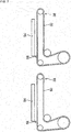
board work system 10, thecircuit board 54 is pushed out toward thework machine 20 on the downstream side by the protrudingsection 58 of theconveyor belt 50, and conveyance of thecircuit boards 54 is simultaneously performed in themultiple work machines 20. Specifically, as shown inFig. 6 , in eachwork machine 20, thecircuit board 54 is conveyed to the working position by theconveyor device 38. Next, in eachwork machine 20, thecircuit board 54 is lifted upward by theboard holding device 40, and thereby clamped and the mounting work is executed on thecircuit board 54. Then, theconveyor belt 50 is caused to orbit in the forward direction by the operation of theconveyor device 38 while the mounting work is executed on thecircuit board 54. At this time, as shown inFig. 7 , theconveyor belt 50 is caused to orbit such that an end face on the opposite side to the conveyance direction of thecircuit board 54 and an end face on the side of the revolving direction of the protrudingsection 58 match in the up-down direction. However, theconveyor belt 50 is caused to orbit such that it is possible to form a predetermined gap (clearance) between an end face on the opposite side to the conveyance direction of thecircuit board 54 and an end face on the side of the revolving direction of the protrudingsection 58 in the up-down direction to prevent thecircuit board 54 from riding up on the protrudingsection 58. - Note that, calibration of the position of the protruding
section 58 is performed prior to mounting work to suitably match the end face on the opposite side to the conveyance direction of thecircuit board 54 and the end face on the revolving direction side of the protrudingsection 58 in the up-down direction. In detail, prior to the mounting work, theconveyor belt 50 is orbited such that the protrudingsection 58 enters an imaging range of themark camera 96 and the protrudingsection 58 is imaged by themark camera 96. Next, the position of the protrudingsection 58 is calculated based on the captured image data. Then, calibration of the position of the protrudingsection 58 is performed based on the position of the calculated protrudingsection 58 and the rotation control position of theelectromagnetic motor 56 that causes theconveyor belt 50 to orbit. Thereby, it is possible to suitably match the end face on the opposite side to the conveyance direction of thecircuit board 54 and the end face on the revolving direction side of the protrudingsection 58 in the up-down direction. - Then, in each
work machine 20, when the mounting work on thecircuit board 54 is completed, the clamping of thecircuit board 54 for which the mounting work is completed is released. Thereby, thecircuit board 54 is lowered and placed on theconveyor belt 50. At this time, as shown inFig. 8 , an end face on the opposite side to the conveyance direction of thecircuit board 54 and an end face on the side of the revolving direction of the protrudingsection 58 engage. Then, in themultiple work machines 20, when clamping of thecircuit board 54 is released, theconveyor device 38 simultaneously operates, and as shown inFig. 9 ,multiple circuit boards 54 are simultaneously conveyed toward thework machine 20 on the downstream side. Thereby, in the manner of the method in the related art, there is no need for thework machine 20 on the upstream side to be on standby for discharge of thecircuit board 54 by thework machine 20 on the downstream side and it is possible to prevent a reduction of throughput. In addition, the conveyedcircuit board 54 is engaged with the protrudingsection 58, and therefore is able to reliably convey thecircuit board 54 to thework machine 20 on the downstream side. Thereby, it is possible to reliably prevent interference of thecircuit boards 54 with each other due to conveyance errors and the like of thecircuit boards 54, and it is possible to suitably secure simultaneous conveyance of thecircuit boards 54. - Note that, in the
board work system 10, in all of the eightwork machines 20, conveyance of thecircuit board 54 is not simultaneously performed, the eightwork machines 20 are divided into two groups, and thecircuit boards 54 are simultaneously conveyed in each of the two groups. In detail, the eightwork machines 20 are divided into a group ofwork machines 20 further on the downstream side than thework machine 20 with the longest mounting work time and a group ofwork machines 20 on the upstream side that includes thework machine 20 with the longest mounting work time. Then, in each group, in all of thework machines 20 of each group, mounting work is completed and clamping is released, then thecircuit boards 54 are simultaneously conveyed. - Specifically, for example, in a case where the mounting work time is the longest in the
work machine 20d out of the eightwork machines 20, the eightwork machines 20 are divided into two groups of a group of fouradjacent work machines 20a to 20d and a group of fouradjacent work machines 20e to 20h. Then, in the group of fourwork machines 20e to 20h, in all of the fourwork machines 20e to 20h, mounting work is completed and clamping is released, then thecircuit boards 54 are simultaneously conveyed. In addition, in the group of fourwork machines 20a to 20d, in all of the fourwork machines 20a to 20d, mounting work is completed, then thecircuit boards 54 are simultaneously conveyed. In this manner, it is not necessary to stand by for completion of the mounting work in thework machine 20d with the longest mounting work in the group of the fourwork machines 20e to 20h by simultaneously performing conveyance of thecircuit boards 54 in each of the two groups. Thereby, it is possible to achieve further shortening of throughput. - In addition, for example, in the group of the four
work machines 20e to 20h, in a case where the mounting work time of thework machine 20h on the most downstream side is shorter than the mounting work time of the other threework machines 20e to 20g, in thework machine 20h furthest on the downstream, thecircuit board 54 may be conveyed after the mounting work is completed in thework machine 20h and clamping is released, and in the other threework machines 20e to 20g, thecircuit board 54 may be conveyed after mounting work of all of the threework machines 20e to 20g is completed and clamping is released. In this manner, in thework machine 20h on the most downstream side, it is possible to achieve further shortening of throughput by immediately conveying thecircuit board 54 by completing mounting work of thework machine 20h. - However, it may not be possible to shorten throughput according to the difference between the longest work time out of the group of the four
work machines 20a to 20d and the longest work time out of the group of the fourwork machines 20e to 20h. Specifically, for example, with a longest work time of 60 seconds out of the group of fourwork machines 20a to 20d, the difference in work time of the two groups is 10 seconds in a case where the longest work time out of the group of the fourwork machines 20e to 20h is 50 seconds. In addition, it is assumed that the conveyance time of thecircuit board 54 by theconveyance device 30 is 5 seconds. In such a case, when thecircuit boards 54 are simultaneously conveyed in each of the two groups, it is necessary for the group of the fourwork machines 20e to 20h on the downstream side to stand by for 5 seconds that is the conveyance time of thecircuit board 54. Meanwhile, when thecircuit boards 54 are collectively and simultaneously conveyed in each of the eightwork machines 20a to 20h, it is necessary for the group of thework machines 20e to 20h on the downstream side to stand by for 10 seconds that is a difference of work time between the two groups. That is, in a case where the difference of work time between the two groups is longer than the conveyance time of thecircuit board 54 by theconveyance device 30, it is possible to achieve shortening of throughput by performing simultaneous conveyance of thecircuit boards 54 in each of the two groups. - In addition, with a longest work time of 60 seconds out of the group of four
work machines 20a to 20d, the difference in work time of the two groups is 4 seconds in a case where the longest work time out of the group of the fourwork machines 20e to 20h is 56 seconds. In addition, it is assumed that the conveyance time of thecircuit board 54 by theconveyance device 30 is 5 seconds. In such a case, when thecircuit boards 54 are simultaneously conveyed in each of the two groups, it is necessary for the group of the fourwork machines 20e to 20h on the downstream side to stand by for 5 seconds that is the conveyance time of thecircuit board 54. Meanwhile, when thecircuit boards 54 are collectively and simultaneously conveyed in each of the eightwork machines 20a to 20h, it is necessary for the group of thework machines 20e to 20h on the downstream side to stand by for 4 seconds that is a difference of work time between the two groups. That is, in a case where the difference of work time between the two groups is longer than the conveyance time of thecircuit board 54 by theconveyance device 30, it is not possible to achieve shortening of throughput even by performing simultaneous conveyance of thecircuit boards 54 in each of the two groups. In consideration of such, in theboard work system 10, in a case where the difference of work time of the two groups is longer than the conveyance time of thecircuit board 54 by theconveyance device 30, thecircuit boards 54 in each of the two groups are simultaneously conveyed, and in a case where the difference of work time of the two groups is shorter than the conveyance time of thecircuit board 54 by theconveyance device 30, thecircuit boards 54 in the eightwork machines 20a to 20h are collectively and simultaneously conveyed. - Note that, as shown in
Fig. 5 , thecontroller 102 of thecontrol device 100 has arotation control section 110 and aconveyance control section 112. Therotation control section 110 is a functional portion for causing theconveyor belt 50 to orbit to cause the protrudingsection 58 to move to a position at which it is possible to engage with thecircuit board 54. Theconveyance control section 112 is a functional portion for conveying thecircuit board 54 in a state of engaging with the protrudingsection 58. - Incidentally, in the applied example, the
board work system 10 is an example of a board work system. Thework machine 20 is an example of a board work machine. Theconveyance device 30 is an example of a conveyance device. Theboard holding device 40 is an example of a clamping device. Theconveyor belt 50 is an example of a conveyor belt. The protrudingsection 58 is an example of a protruding section. Thecontrol device 100 is an example of a control device. Therotation control section 110 is an example of a rotation control section. Theconveyance control section 112 is an example of a conveyance control section. - Note that, the present invention is not limited to the applied example described above, and it is possible to carry out the present invention in various aspects subjected to various modifications and improvements based on the knowledge of a person skilled in the art. Specifically, for example, in the applied example, the
conveyor belt 50 rotates while thecircuit board 54 is clamped, the end face on the opposite side to the conveyance direction of thecircuit board 54 and the end face on the revolving direction side of the protrudingsection 58 match in the up-down direction, but theconveyor belt 50 may be rotated such that the protrudingsection 58 is positioned further on the upstream side than the end face on the opposite side to the conveyance direction of thecircuit board 54. At this time, it is necessary for the protrudingsection 58 to be positioned further on the downstream side than the end face on the conveyance direction side of the circuit board that is newly brought into thework machine 20. In this manner, in a case where the protrudingsection 58 is moved, when thecircuit board 54 is conveyed, thecircuit board 54 and the protrudingsection 58 are not engaged. However, in a case where thecircuit board 54 is not suitably conveyed for some reason, thecircuit board 54 engages with the protrudingsection 58, and is pushed out toward thework machine 20 on the downstream side by the protrudingsection 58. Thereby, even in a case where the protrudingsection 58 is moved further to the downstream side than the end face on the opposite side to the conveyance direction of thecircuit board 54, it is possible to exhibit the same effect as the applied example. - In addition, in the applied example, the shape of the protruding
section 58 is a plate shape, but as long as it is possible to engage with thecircuit board 54, it is possible to adopt various shapes for the protrudingsection 58. In addition, in the applied example, one protrudingsection 58 is formed on theconveyor belt 50, but it is possible to form multiple protrudingsections 58. - In addition, in the applied example, calibration of the position of the projecting
portion 58 is performed based on captured image data of the projectingportion 58, but it is possible to detect the projectingportion 58 using thedetection sensor 68 and perform calibration of the position of the protrudingsection 58 using the detection value. - 10: board work system, 20: work device (board work machine), 30: conveyance device, 40: board holding device (clamping device), 50: conveyor belt, 58: protruding section, 100: control device, 110: rotation control section, 112: conveyance control section
Claims (4)
- A board work machine comprising:a conveyance device having a conveyor belt on which a circuit board is placed and a clamping device that clamps the circuit board in a state in which the circuit board has been moved on the conveyor belt; anda control device that controls operation of the conveyance device,wherein a protruding section is formed on a placement face of the conveyor belt, andthe control device has a rotation control section that rotates the conveyor belt such that the protruding section is positioned on the upstream side of an end face on an opposite side to a conveyance direction of the circuit board in a case where the clamp is released, while the circuit board is clamped by the clamping device.
- The board work machine according to Claim 1,
wherein the rotation control section rotates the conveyor belt such that the protruding section is positioned on the upstream side of an end face on an opposite side to a conveyance direction of the circuit board in a case where the clamp is released and on the downstream side of an end face on the conveyance direction side of the circuit board that is newly brought into the board work machine by the conveyance device. - The board work machine according to Claim 1 or Claim 2,
wherein the control device has a conveyance control section that conveys the circuit board in a state in which the protruding section is engaged with an end face on an opposite side to the conveyance direction of the circuit board after clamping of the circuit board is released. - A board work system comprising:a plurality of the board work machines according to any one of Claims 1 to 3 arranged in one row,the system executing work on a circuit board that is conveyed from the board work machine disposed on the upstream side of the plurality of board work machines to the board work machine disposed on the downstream side of the plurality of board work machines,wherein the control device has a conveyance control section that simultaneously conveys the circuit boards after the clamping of the circuit boards is released in two or more adjacent board work machines out of the plurality of board work machines.
Applications Claiming Priority (1)
| Application Number | Priority Date | Filing Date | Title |
|---|---|---|---|
| PCT/JP2015/070259 WO2017009967A1 (en) | 2015-07-15 | 2015-07-15 | Board working machine and board working system |
Publications (3)
| Publication Number | Publication Date |
|---|---|
| EP3324718A1 true EP3324718A1 (en) | 2018-05-23 |
| EP3324718A4 EP3324718A4 (en) | 2018-07-11 |
| EP3324718B1 EP3324718B1 (en) | 2020-06-10 |
Family
ID=57757833
Family Applications (1)
| Application Number | Title | Priority Date | Filing Date |
|---|---|---|---|
| EP15898279.3A Active EP3324718B1 (en) | 2015-07-15 | 2015-07-15 | Board working machine and board working system |
Country Status (5)
| Country | Link |
|---|---|
| US (1) | US10647510B2 (en) |
| EP (1) | EP3324718B1 (en) |
| JP (1) | JP6539738B2 (en) |
| CN (1) | CN107926140B (en) |
| WO (1) | WO2017009967A1 (en) |
Family Cites Families (31)
| Publication number | Priority date | Publication date | Assignee | Title |
|---|---|---|---|---|
| US3513963A (en) * | 1968-07-01 | 1970-05-26 | Donald H Witte | Conveyor belt for elongated articles |
| DE2061466A1 (en) * | 1970-12-14 | 1972-06-29 | Schmall Automation U Elektroni | Method and device for conveying the substrate from circuit carriers |
| US4436806A (en) * | 1981-01-16 | 1984-03-13 | W. R. Grace & Co. | Method and apparatus for making printed circuit boards |
| JPS60169148A (en) * | 1984-02-13 | 1985-09-02 | Dainippon Screen Mfg Co Ltd | Method and apparatus for conveying substrate |
| JPS61168446A (en) * | 1985-01-21 | 1986-07-30 | Fuji Kikai Seizo Kk | Printed board positioning device |
| US4723652A (en) * | 1986-03-17 | 1988-02-09 | Rich Dennis E | Accumulator apparatus for printed circuit boards |
| US4928806A (en) * | 1988-04-08 | 1990-05-29 | Honeywell Inc. | System for removing a pallet from a moving transfer mechanism and for accurately locking the pallet at a precise location |
| US4947980A (en) * | 1989-03-02 | 1990-08-14 | American Telephone And Telegraph Company | Method and apparatus for stopping and clamping substrates |
| US5094584A (en) * | 1989-04-06 | 1992-03-10 | Hewlett-Packard Company | Method and apparatus for automatically changing printed circuit board test fixtures |
| JP3245746B2 (en) * | 1989-12-08 | 2002-01-15 | エス イー ゲー シュバイツェリッシェ インズストリー‐ゲゼルシャフト | Column forming device for articles, especially chocolate bars |
| US5115905A (en) * | 1990-06-14 | 1992-05-26 | Compaq Computer Corporation | Magnetically secured conveyor system for printed circuit assemblies |
| JP2517178B2 (en) * | 1991-03-04 | 1996-07-24 | 松下電器産業株式会社 | Electronic component mounting method |
| JPH04131997U (en) * | 1991-05-29 | 1992-12-04 | 天竜精機株式会社 | Electronic component mounting equipment |
| JPH0539124A (en) * | 1991-08-01 | 1993-02-19 | Matsushita Electric Ind Co Ltd | Circuit board storage device |
| US6256869B1 (en) * | 1996-07-30 | 2001-07-10 | Fuji Machine Mfg. Co., Ltd. | Electronic-component mounting system |
| US6321904B1 (en) * | 2000-05-04 | 2001-11-27 | Charles L. Mitchell | Conveyor belt with locking member for holder elements |
| US6651461B2 (en) * | 2001-05-31 | 2003-11-25 | 3M Innovative Properties Company | Conveyor belt |
| KR100412273B1 (en) * | 2001-11-22 | 2003-12-31 | 미래산업 주식회사 | Apparatus for Transferring Printed Circuit Board |
| TWI287752B (en) * | 2005-01-31 | 2007-10-01 | All Fine Technology Co Ltd | Composite equipment for automatic marking and reading |
| US20070238565A1 (en) * | 2006-03-27 | 2007-10-11 | Ron Marler | Draper belt having improved durability |
| US20070179002A1 (en) * | 2006-02-01 | 2007-08-02 | Mol Belting Company | Conveyor with roller on belt return span |
| JP4819598B2 (en) * | 2006-06-29 | 2011-11-24 | ヤマハ発動機株式会社 | Surface mount machine |
| KR100871893B1 (en) * | 2007-03-09 | 2008-12-05 | 유병석 | Transfer device of printed circuit board and printed circuit board used therefor |
| US20100326797A1 (en) * | 2009-04-23 | 2010-12-30 | Applied Materials, Inc. | Carrier for transporting solar cell substrates |
| JP5358494B2 (en) * | 2010-03-19 | 2013-12-04 | ヤマハ発動機株式会社 | Substrate transfer device, substrate transfer method, and surface mounter |
| JP5597050B2 (en) * | 2010-07-15 | 2014-10-01 | 富士機械製造株式会社 | Substrate stop position control method and apparatus, and substrate mounting position control method |
| JP5780905B2 (en) * | 2011-09-28 | 2015-09-16 | 富士機械製造株式会社 | Board work system |
| JP5814457B2 (en) * | 2012-02-21 | 2015-11-17 | 富士機械製造株式会社 | Substrate transfer device |
| JP6180750B2 (en) * | 2012-02-22 | 2017-08-16 | Juki株式会社 | Board work system |
| US8839949B2 (en) * | 2012-04-13 | 2014-09-23 | John Bean Technologies Corporation | Determination and correction of conveyor belt speed/location |
| JP6043871B2 (en) * | 2013-05-21 | 2016-12-14 | ヤマハ発動機株式会社 | Substrate transport apparatus, surface mounter, and substrate transport method |
-
2015
- 2015-07-15 JP JP2017528070A patent/JP6539738B2/en active Active
- 2015-07-15 US US15/743,446 patent/US10647510B2/en active Active
- 2015-07-15 WO PCT/JP2015/070259 patent/WO2017009967A1/en not_active Ceased
- 2015-07-15 CN CN201580081484.XA patent/CN107926140B/en active Active
- 2015-07-15 EP EP15898279.3A patent/EP3324718B1/en active Active
Also Published As
| Publication number | Publication date |
|---|---|
| EP3324718A4 (en) | 2018-07-11 |
| JP6539738B2 (en) | 2019-07-03 |
| WO2017009967A1 (en) | 2017-01-19 |
| EP3324718B1 (en) | 2020-06-10 |
| CN107926140A (en) | 2018-04-17 |
| US20180201446A1 (en) | 2018-07-19 |
| JPWO2017009967A1 (en) | 2018-04-26 |
| US10647510B2 (en) | 2020-05-12 |
| CN107926140B (en) | 2020-01-03 |
Similar Documents
| Publication | Publication Date | Title |
|---|---|---|
| CN103596761B (en) | Screen printing device | |
| JP2009027202A (en) | Method and device for controlling substrate stop position | |
| CN103619594B (en) | Screen printing apparatus | |
| CN103327802B (en) | Apparatus for mounting component and component mounting method | |
| JP6727768B2 (en) | Board working equipment | |
| EP2897449B1 (en) | Work system for substrate and workbench-quantity-determining program | |
| EP2876990B1 (en) | Work system and work machines for substrates | |
| EP3125664B1 (en) | Component mounting device | |
| EP3324718B1 (en) | Board working machine and board working system | |
| JP2022118841A (en) | Work machine and interference avoiding method | |
| EP3089572B1 (en) | Substrate work device | |
| EP3694302B1 (en) | Substrate work system | |
| JP7386754B2 (en) | Component mounting machine | |
| CN103619593B (en) | Screen printing apparatus | |
| JP5536438B2 (en) | Screen printing device | |
| US10935963B2 (en) | Required accuracy setting device | |
| US9296198B2 (en) | Screen printing apparatus | |
| JP4194813B2 (en) | Backup pin setup change method and setup change device |
Legal Events
| Date | Code | Title | Description |
|---|---|---|---|
| STAA | Information on the status of an ep patent application or granted ep patent |
Free format text: STATUS: THE INTERNATIONAL PUBLICATION HAS BEEN MADE |
|
| PUAI | Public reference made under article 153(3) epc to a published international application that has entered the european phase |
Free format text: ORIGINAL CODE: 0009012 |
|
| STAA | Information on the status of an ep patent application or granted ep patent |
Free format text: STATUS: REQUEST FOR EXAMINATION WAS MADE |
|
| 17P | Request for examination filed |
Effective date: 20180111 |
|
| AK | Designated contracting states |
Kind code of ref document: A1 Designated state(s): AL AT BE BG CH CY CZ DE DK EE ES FI FR GB GR HR HU IE IS IT LI LT LU LV MC MK MT NL NO PL PT RO RS SE SI SK SM TR |
|
| AX | Request for extension of the european patent |
Extension state: BA ME |
|
| A4 | Supplementary search report drawn up and despatched |
Effective date: 20180611 |
|
| RIC1 | Information provided on ipc code assigned before grant |
Ipc: B65G 43/00 20060101ALI20180604BHEP Ipc: H05K 13/00 20060101ALI20180604BHEP Ipc: B65G 15/44 20060101ALI20180604BHEP Ipc: H05K 13/02 20060101AFI20180604BHEP |
|
| DAV | Request for validation of the european patent (deleted) | ||
| DAX | Request for extension of the european patent (deleted) | ||
| RAP1 | Party data changed (applicant data changed or rights of an application transferred) |
Owner name: FUJI CORPORATION |
|
| RIN1 | Information on inventor provided before grant (corrected) |
Inventor name: KAWAI, HIDETOSHI |
|
| GRAP | Despatch of communication of intention to grant a patent |
Free format text: ORIGINAL CODE: EPIDOSNIGR1 |
|
| STAA | Information on the status of an ep patent application or granted ep patent |
Free format text: STATUS: GRANT OF PATENT IS INTENDED |
|
| INTG | Intention to grant announced |
Effective date: 20200213 |
|
| RIN1 | Information on inventor provided before grant (corrected) |
Inventor name: KAWAI, HIDETOSHI |
|
| GRAS | Grant fee paid |
Free format text: ORIGINAL CODE: EPIDOSNIGR3 |
|
| GRAA | (expected) grant |
Free format text: ORIGINAL CODE: 0009210 |
|
| STAA | Information on the status of an ep patent application or granted ep patent |
Free format text: STATUS: THE PATENT HAS BEEN GRANTED |
|
| AK | Designated contracting states |
Kind code of ref document: B1 Designated state(s): AL AT BE BG CH CY CZ DE DK EE ES FI FR GB GR HR HU IE IS IT LI LT LU LV MC MK MT NL NO PL PT RO RS SE SI SK SM TR |
|
| REG | Reference to a national code |
Ref country code: GB Ref legal event code: FG4D |
|
| REG | Reference to a national code |
Ref country code: CH Ref legal event code: EP Ref country code: AT Ref legal event code: REF Ref document number: 1280225 Country of ref document: AT Kind code of ref document: T Effective date: 20200615 |
|
| REG | Reference to a national code |
Ref country code: DE Ref legal event code: R096 Ref document number: 602015054204 Country of ref document: DE |
|
| REG | Reference to a national code |
Ref country code: IE Ref legal event code: FG4D |
|
| REG | Reference to a national code |
Ref country code: LT Ref legal event code: MG4D |
|
| PG25 | Lapsed in a contracting state [announced via postgrant information from national office to epo] |
Ref country code: LT Free format text: LAPSE BECAUSE OF FAILURE TO SUBMIT A TRANSLATION OF THE DESCRIPTION OR TO PAY THE FEE WITHIN THE PRESCRIBED TIME-LIMIT Effective date: 20200610 Ref country code: FI Free format text: LAPSE BECAUSE OF FAILURE TO SUBMIT A TRANSLATION OF THE DESCRIPTION OR TO PAY THE FEE WITHIN THE PRESCRIBED TIME-LIMIT Effective date: 20200610 Ref country code: SE Free format text: LAPSE BECAUSE OF FAILURE TO SUBMIT A TRANSLATION OF THE DESCRIPTION OR TO PAY THE FEE WITHIN THE PRESCRIBED TIME-LIMIT Effective date: 20200610 Ref country code: GR Free format text: LAPSE BECAUSE OF FAILURE TO SUBMIT A TRANSLATION OF THE DESCRIPTION OR TO PAY THE FEE WITHIN THE PRESCRIBED TIME-LIMIT Effective date: 20200911 Ref country code: NO Free format text: LAPSE BECAUSE OF FAILURE TO SUBMIT A TRANSLATION OF THE DESCRIPTION OR TO PAY THE FEE WITHIN THE PRESCRIBED TIME-LIMIT Effective date: 20200910 |
|
| REG | Reference to a national code |
Ref country code: NL Ref legal event code: MP Effective date: 20200610 |
|
| PG25 | Lapsed in a contracting state [announced via postgrant information from national office to epo] |
Ref country code: BG Free format text: LAPSE BECAUSE OF FAILURE TO SUBMIT A TRANSLATION OF THE DESCRIPTION OR TO PAY THE FEE WITHIN THE PRESCRIBED TIME-LIMIT Effective date: 20200910 Ref country code: HR Free format text: LAPSE BECAUSE OF FAILURE TO SUBMIT A TRANSLATION OF THE DESCRIPTION OR TO PAY THE FEE WITHIN THE PRESCRIBED TIME-LIMIT Effective date: 20200610 Ref country code: RS Free format text: LAPSE BECAUSE OF FAILURE TO SUBMIT A TRANSLATION OF THE DESCRIPTION OR TO PAY THE FEE WITHIN THE PRESCRIBED TIME-LIMIT Effective date: 20200610 Ref country code: LV Free format text: LAPSE BECAUSE OF FAILURE TO SUBMIT A TRANSLATION OF THE DESCRIPTION OR TO PAY THE FEE WITHIN THE PRESCRIBED TIME-LIMIT Effective date: 20200610 |
|
| REG | Reference to a national code |
Ref country code: AT Ref legal event code: MK05 Ref document number: 1280225 Country of ref document: AT Kind code of ref document: T Effective date: 20200610 |
|
| PG25 | Lapsed in a contracting state [announced via postgrant information from national office to epo] |
Ref country code: NL Free format text: LAPSE BECAUSE OF FAILURE TO SUBMIT A TRANSLATION OF THE DESCRIPTION OR TO PAY THE FEE WITHIN THE PRESCRIBED TIME-LIMIT Effective date: 20200610 Ref country code: AL Free format text: LAPSE BECAUSE OF FAILURE TO SUBMIT A TRANSLATION OF THE DESCRIPTION OR TO PAY THE FEE WITHIN THE PRESCRIBED TIME-LIMIT Effective date: 20200610 |
|
| PG25 | Lapsed in a contracting state [announced via postgrant information from national office to epo] |
Ref country code: SM Free format text: LAPSE BECAUSE OF FAILURE TO SUBMIT A TRANSLATION OF THE DESCRIPTION OR TO PAY THE FEE WITHIN THE PRESCRIBED TIME-LIMIT Effective date: 20200610 Ref country code: EE Free format text: LAPSE BECAUSE OF FAILURE TO SUBMIT A TRANSLATION OF THE DESCRIPTION OR TO PAY THE FEE WITHIN THE PRESCRIBED TIME-LIMIT Effective date: 20200610 Ref country code: AT Free format text: LAPSE BECAUSE OF FAILURE TO SUBMIT A TRANSLATION OF THE DESCRIPTION OR TO PAY THE FEE WITHIN THE PRESCRIBED TIME-LIMIT Effective date: 20200610 Ref country code: RO Free format text: LAPSE BECAUSE OF FAILURE TO SUBMIT A TRANSLATION OF THE DESCRIPTION OR TO PAY THE FEE WITHIN THE PRESCRIBED TIME-LIMIT Effective date: 20200610 Ref country code: IT Free format text: LAPSE BECAUSE OF FAILURE TO SUBMIT A TRANSLATION OF THE DESCRIPTION OR TO PAY THE FEE WITHIN THE PRESCRIBED TIME-LIMIT Effective date: 20200610 Ref country code: CZ Free format text: LAPSE BECAUSE OF FAILURE TO SUBMIT A TRANSLATION OF THE DESCRIPTION OR TO PAY THE FEE WITHIN THE PRESCRIBED TIME-LIMIT Effective date: 20200610 Ref country code: PT Free format text: LAPSE BECAUSE OF FAILURE TO SUBMIT A TRANSLATION OF THE DESCRIPTION OR TO PAY THE FEE WITHIN THE PRESCRIBED TIME-LIMIT Effective date: 20201012 Ref country code: ES Free format text: LAPSE BECAUSE OF FAILURE TO SUBMIT A TRANSLATION OF THE DESCRIPTION OR TO PAY THE FEE WITHIN THE PRESCRIBED TIME-LIMIT Effective date: 20200610 |
|
| PG25 | Lapsed in a contracting state [announced via postgrant information from national office to epo] |
Ref country code: PL Free format text: LAPSE BECAUSE OF FAILURE TO SUBMIT A TRANSLATION OF THE DESCRIPTION OR TO PAY THE FEE WITHIN THE PRESCRIBED TIME-LIMIT Effective date: 20200610 Ref country code: SK Free format text: LAPSE BECAUSE OF FAILURE TO SUBMIT A TRANSLATION OF THE DESCRIPTION OR TO PAY THE FEE WITHIN THE PRESCRIBED TIME-LIMIT Effective date: 20200610 Ref country code: IS Free format text: LAPSE BECAUSE OF FAILURE TO SUBMIT A TRANSLATION OF THE DESCRIPTION OR TO PAY THE FEE WITHIN THE PRESCRIBED TIME-LIMIT Effective date: 20201010 |
|
| REG | Reference to a national code |
Ref country code: CH Ref legal event code: PL |
|
| REG | Reference to a national code |
Ref country code: DE Ref legal event code: R097 Ref document number: 602015054204 Country of ref document: DE |
|
| PG25 | Lapsed in a contracting state [announced via postgrant information from national office to epo] |
Ref country code: MC Free format text: LAPSE BECAUSE OF FAILURE TO SUBMIT A TRANSLATION OF THE DESCRIPTION OR TO PAY THE FEE WITHIN THE PRESCRIBED TIME-LIMIT Effective date: 20200610 |
|
| PLBE | No opposition filed within time limit |
Free format text: ORIGINAL CODE: 0009261 |
|
| STAA | Information on the status of an ep patent application or granted ep patent |
Free format text: STATUS: NO OPPOSITION FILED WITHIN TIME LIMIT |
|
| REG | Reference to a national code |
Ref country code: BE Ref legal event code: MM Effective date: 20200731 |
|
| PG25 | Lapsed in a contracting state [announced via postgrant information from national office to epo] |
Ref country code: CH Free format text: LAPSE BECAUSE OF NON-PAYMENT OF DUE FEES Effective date: 20200731 Ref country code: DK Free format text: LAPSE BECAUSE OF FAILURE TO SUBMIT A TRANSLATION OF THE DESCRIPTION OR TO PAY THE FEE WITHIN THE PRESCRIBED TIME-LIMIT Effective date: 20200610 Ref country code: LU Free format text: LAPSE BECAUSE OF NON-PAYMENT OF DUE FEES Effective date: 20200715 Ref country code: LI Free format text: LAPSE BECAUSE OF NON-PAYMENT OF DUE FEES Effective date: 20200731 |
|
| 26N | No opposition filed |
Effective date: 20210311 |
|
| GBPC | Gb: european patent ceased through non-payment of renewal fee |
Effective date: 20200910 |
|
| PG25 | Lapsed in a contracting state [announced via postgrant information from national office to epo] |
Ref country code: SI Free format text: LAPSE BECAUSE OF FAILURE TO SUBMIT A TRANSLATION OF THE DESCRIPTION OR TO PAY THE FEE WITHIN THE PRESCRIBED TIME-LIMIT Effective date: 20200610 Ref country code: BE Free format text: LAPSE BECAUSE OF NON-PAYMENT OF DUE FEES Effective date: 20200731 |
|
| PG25 | Lapsed in a contracting state [announced via postgrant information from national office to epo] |
Ref country code: FR Free format text: LAPSE BECAUSE OF NON-PAYMENT OF DUE FEES Effective date: 20200810 |
|
| PG25 | Lapsed in a contracting state [announced via postgrant information from national office to epo] |
Ref country code: IE Free format text: LAPSE BECAUSE OF NON-PAYMENT OF DUE FEES Effective date: 20200715 Ref country code: GB Free format text: LAPSE BECAUSE OF NON-PAYMENT OF DUE FEES Effective date: 20200910 |
|
| PG25 | Lapsed in a contracting state [announced via postgrant information from national office to epo] |
Ref country code: TR Free format text: LAPSE BECAUSE OF FAILURE TO SUBMIT A TRANSLATION OF THE DESCRIPTION OR TO PAY THE FEE WITHIN THE PRESCRIBED TIME-LIMIT Effective date: 20200610 Ref country code: MT Free format text: LAPSE BECAUSE OF FAILURE TO SUBMIT A TRANSLATION OF THE DESCRIPTION OR TO PAY THE FEE WITHIN THE PRESCRIBED TIME-LIMIT Effective date: 20200610 Ref country code: CY Free format text: LAPSE BECAUSE OF FAILURE TO SUBMIT A TRANSLATION OF THE DESCRIPTION OR TO PAY THE FEE WITHIN THE PRESCRIBED TIME-LIMIT Effective date: 20200610 |
|
| PG25 | Lapsed in a contracting state [announced via postgrant information from national office to epo] |
Ref country code: MK Free format text: LAPSE BECAUSE OF FAILURE TO SUBMIT A TRANSLATION OF THE DESCRIPTION OR TO PAY THE FEE WITHIN THE PRESCRIBED TIME-LIMIT Effective date: 20200610 |
|
| P01 | Opt-out of the competence of the unified patent court (upc) registered |
Effective date: 20230328 |
|
| PGFP | Annual fee paid to national office [announced via postgrant information from national office to epo] |
Ref country code: DE Payment date: 20250528 Year of fee payment: 11 |