EP3324486A1 - Glass plate module - Google Patents
Glass plate module Download PDFInfo
- Publication number
- EP3324486A1 EP3324486A1 EP16824473.9A EP16824473A EP3324486A1 EP 3324486 A1 EP3324486 A1 EP 3324486A1 EP 16824473 A EP16824473 A EP 16824473A EP 3324486 A1 EP3324486 A1 EP 3324486A1
- Authority
- EP
- European Patent Office
- Prior art keywords
- glass plate
- electrically conductive
- lead
- conductive layer
- free solder
- Prior art date
- Legal status (The legal status is an assumption and is not a legal conclusion. Google has not performed a legal analysis and makes no representation as to the accuracy of the status listed.)
- Pending
Links
Images


Classifications
-
- B—PERFORMING OPERATIONS; TRANSPORTING
- B32—LAYERED PRODUCTS
- B32B—LAYERED PRODUCTS, i.e. PRODUCTS BUILT-UP OF STRATA OF FLAT OR NON-FLAT, e.g. CELLULAR OR HONEYCOMB, FORM
- B32B17/00—Layered products essentially comprising sheet glass, or glass, slag, or like fibres
- B32B17/06—Layered products essentially comprising sheet glass, or glass, slag, or like fibres comprising glass as the main or only constituent of a layer, next to another layer of a specific material
- B32B17/10—Layered products essentially comprising sheet glass, or glass, slag, or like fibres comprising glass as the main or only constituent of a layer, next to another layer of a specific material of synthetic resin
- B32B17/10005—Layered products essentially comprising sheet glass, or glass, slag, or like fibres comprising glass as the main or only constituent of a layer, next to another layer of a specific material of synthetic resin laminated safety glass or glazing
- B32B17/10165—Functional features of the laminated safety glass or glazing
- B32B17/10376—Laminated safety glass or glazing containing metal wires
- B32B17/10385—Laminated safety glass or glazing containing metal wires for ohmic resistance heating
-
- B—PERFORMING OPERATIONS; TRANSPORTING
- B23—MACHINE TOOLS; METAL-WORKING NOT OTHERWISE PROVIDED FOR
- B23K—SOLDERING OR UNSOLDERING; WELDING; CLADDING OR PLATING BY SOLDERING OR WELDING; CUTTING BY APPLYING HEAT LOCALLY, e.g. FLAME CUTTING; WORKING BY LASER BEAM
- B23K1/00—Soldering, e.g. brazing, or unsoldering
- B23K1/0008—Soldering, e.g. brazing, or unsoldering specially adapted for particular articles or work
-
- B—PERFORMING OPERATIONS; TRANSPORTING
- B32—LAYERED PRODUCTS
- B32B—LAYERED PRODUCTS, i.e. PRODUCTS BUILT-UP OF STRATA OF FLAT OR NON-FLAT, e.g. CELLULAR OR HONEYCOMB, FORM
- B32B17/00—Layered products essentially comprising sheet glass, or glass, slag, or like fibres
- B32B17/06—Layered products essentially comprising sheet glass, or glass, slag, or like fibres comprising glass as the main or only constituent of a layer, next to another layer of a specific material
- B32B17/10—Layered products essentially comprising sheet glass, or glass, slag, or like fibres comprising glass as the main or only constituent of a layer, next to another layer of a specific material of synthetic resin
- B32B17/10005—Layered products essentially comprising sheet glass, or glass, slag, or like fibres comprising glass as the main or only constituent of a layer, next to another layer of a specific material of synthetic resin laminated safety glass or glazing
- B32B17/1055—Layered products essentially comprising sheet glass, or glass, slag, or like fibres comprising glass as the main or only constituent of a layer, next to another layer of a specific material of synthetic resin laminated safety glass or glazing characterized by the resin layer, i.e. interlayer
-
- H—ELECTRICITY
- H01—ELECTRIC ELEMENTS
- H01R—ELECTRICALLY-CONDUCTIVE CONNECTIONS; STRUCTURAL ASSOCIATIONS OF A PLURALITY OF MUTUALLY-INSULATED ELECTRICAL CONNECTING ELEMENTS; COUPLING DEVICES; CURRENT COLLECTORS
- H01R12/00—Structural associations of a plurality of mutually-insulated electrical connecting elements, specially adapted for printed circuits, e.g. printed circuit boards [PCB], flat or ribbon cables, or like generally planar structures, e.g. terminal strips, terminal blocks; Coupling devices specially adapted for printed circuits, flat or ribbon cables, or like generally planar structures; Terminals specially adapted for contact with, or insertion into, printed circuits, flat or ribbon cables, or like generally planar structures
- H01R12/50—Fixed connections
- H01R12/51—Fixed connections for rigid printed circuits or like structures
- H01R12/55—Fixed connections for rigid printed circuits or like structures characterised by the terminals
- H01R12/57—Fixed connections for rigid printed circuits or like structures characterised by the terminals surface mounting terminals
-
- H—ELECTRICITY
- H01—ELECTRIC ELEMENTS
- H01R—ELECTRICALLY-CONDUCTIVE CONNECTIONS; STRUCTURAL ASSOCIATIONS OF A PLURALITY OF MUTUALLY-INSULATED ELECTRICAL CONNECTING ELEMENTS; COUPLING DEVICES; CURRENT COLLECTORS
- H01R4/00—Electrically-conductive connections between two or more conductive members in direct contact, i.e. touching one another; Means for effecting or maintaining such contact; Electrically-conductive connections having two or more spaced connecting locations for conductors and using contact members penetrating insulation
- H01R4/02—Soldered or welded connections
- H01R4/025—Soldered or welded connections with built-in heat generating elements
-
- H—ELECTRICITY
- H05—ELECTRIC TECHNIQUES NOT OTHERWISE PROVIDED FOR
- H05B—ELECTRIC HEATING; ELECTRIC LIGHT SOURCES NOT OTHERWISE PROVIDED FOR; CIRCUIT ARRANGEMENTS FOR ELECTRIC LIGHT SOURCES, IN GENERAL
- H05B3/00—Ohmic-resistance heating
- H05B3/84—Heating arrangements specially adapted for transparent or reflecting areas, e.g. for demisting or de-icing windows, mirrors or vehicle windshields
- H05B3/86—Heating arrangements specially adapted for transparent or reflecting areas, e.g. for demisting or de-icing windows, mirrors or vehicle windshields the heating conductors being embedded in the transparent or reflecting material
-
- H—ELECTRICITY
- H05—ELECTRIC TECHNIQUES NOT OTHERWISE PROVIDED FOR
- H05K—PRINTED CIRCUITS; CASINGS OR CONSTRUCTIONAL DETAILS OF ELECTRIC APPARATUS; MANUFACTURE OF ASSEMBLAGES OF ELECTRICAL COMPONENTS
- H05K1/00—Printed circuits
- H05K1/02—Details
- H05K1/03—Use of materials for the substrate
- H05K1/0306—Inorganic insulating substrates, e.g. ceramic, glass
-
- H—ELECTRICITY
- H05—ELECTRIC TECHNIQUES NOT OTHERWISE PROVIDED FOR
- H05K—PRINTED CIRCUITS; CASINGS OR CONSTRUCTIONAL DETAILS OF ELECTRIC APPARATUS; MANUFACTURE OF ASSEMBLAGES OF ELECTRICAL COMPONENTS
- H05K1/00—Printed circuits
- H05K1/02—Details
- H05K1/11—Printed elements for providing electric connections to or between printed circuits
-
- H—ELECTRICITY
- H05—ELECTRIC TECHNIQUES NOT OTHERWISE PROVIDED FOR
- H05K—PRINTED CIRCUITS; CASINGS OR CONSTRUCTIONAL DETAILS OF ELECTRIC APPARATUS; MANUFACTURE OF ASSEMBLAGES OF ELECTRICAL COMPONENTS
- H05K1/00—Printed circuits
- H05K1/18—Printed circuits structurally associated with non-printed electric components
-
- H—ELECTRICITY
- H05—ELECTRIC TECHNIQUES NOT OTHERWISE PROVIDED FOR
- H05B—ELECTRIC HEATING; ELECTRIC LIGHT SOURCES NOT OTHERWISE PROVIDED FOR; CIRCUIT ARRANGEMENTS FOR ELECTRIC LIGHT SOURCES, IN GENERAL
- H05B2203/00—Aspects relating to Ohmic resistive heating covered by group H05B3/00
- H05B2203/016—Heaters using particular connecting means
Abstract
Description
- The present invention relates to a glass plate module that is mounted to a window frame of a structure.
- For example,
Patent Literature 1 discloses a connection terminal that is connected to an electrically conductive layer of a glass plate of an automobile. A cable or the like is connected to such a connection terminal, and electric power is supplied to the electrically conductive layer via the connection terminal. - Patent Literature 1:
JP 2014-519149T - Incidentally, a connection terminal such as that described above is fixed to an electrically conductive layer via lead-free solder. However, since lead-free solder is hard when compared with lead-containing solder, there is a risk that if the connection terminal catches on something, or the cable connected to the connection terminal is suddenly pulled, the lead-free solder or the glass plate will crack.
- The present invention was made in order to address the foregoing problem, and it is an object thereof to provide a glass plate module that can prevent the electrically conductive layer and the glass plate from cracking even when an external force is exerted on the connection terminal.
- A glass plate module according to the present invention includes a glass plate, an electrically conductive layer laminated on the glass plate, at least one connection terminal fixed to the electrically conductive layer and made of an electrically conductive material, and lead-free solder for fixing the connection terminal to the electrically conductive layer, wherein the connection terminal includes an installation portion that is fixed to the electrically conductive layer via the lead-free solder, a standing portion that extends from an end portion of the installation portion in a direction away from the glass plate, and a connection portion that is coupled to an end portion of the standing portion on the opposite side to the installation portion and extends in a direction away from the installation portion along a surface direction of the glass plate, the connection portion has a power supply portion to which a cable for supplying electric power to the electrically conductive layer is connected, the power supply portion being located at a position that is spaced apart from the installation portion in the surface direction of the glass plate, and the lead-free solder has a shape such that the nearer to the electrically conductive layer from a surface of the standing portion on the connection portion side, the further the lead-free solder extends to the power supply portion side.
- With this configuration, since the connection terminal has the standing portion provided between the installation portion and the connection portion, when the lead-free solder is melted by heating the connection terminal, the lead-free solder can be prevented from moving to the connection portion. Therefore, when the lead-free solder has solidified and thereby fixed the installation portion and the electrically conductive layer to each other, the connection portion and the electrically conductive layer are not directly connected to each other via the lead-free solder. In addition, the connection portion extends in the direction away from the installation portion along the surface direction of the glass plate. Therefore, for example, when an upward force is exerted on an end portion of the connection portion, due to the moment of rotation of this force, stress concentrates on the coupling portion between the installation portion and the standing portion, or the standing portion above the coupling portion. As a result, concentration of stress on an end portion of a portion of the lead-free solder that is in contact with the electrically conductive layer can be prevented, and the electrically conductive layer and the glass plate can be prevented from cracking at this portion. In particular, according to the present invention, the lead-free solder has a shape such that the nearer to the electrically conductive layer from the surface of the standing portion on the connection portion side, the further the lead-free solder extends to the power supply portion side, and the end portion of the lead-free solder that is in contact with the electrically conductive layer is located at a position that is shifted to the power supply portion side relative to the surface of the standing portion on the connection portion side. Thus, concentration of stress on this end portion can be further prevented.
- Consequently, when an external force is exerted on the connection portion of the connection terminal, for example, even if a worker or a working tool comes into contact therewith, or the cable is unintentionally pulled, the electrically conductive layer and the glass plate can be prevented from cracking as described above, or the connection terminal can be prevented from becoming detached from the electrically conductive layer.
- Note that with regard to the wording "along the surface direction of the glass plate" as used in the description of the configuration of the connection portion according to the present invention, the connection portion does not have to be parallel to the glass plate. It is sufficient that the connection portion generally extends along the surface direction of the glass plate, and at least it is sufficient that the connection portion is not perpendicular to the glass plate. In addition, although the lead-free solder extends "from the surface of the standing portion on the connection portion side", the surface on the connection portion side also contains a surface of the coupling portion between the standing portion and the installation portion. Furthermore, the cable encompasses a thin wire such as a conductor.
- In the above-described glass plate module, it is possible that a length of the standing portion between a surface of the installation portion that faces the electrically conductive layer and a surface of the connection portion that faces the electrically conductive layer is 2 mm or more.
- With this configuration, the lead-free solder that is melted as described above is even less likely to move to the connection portion against gravity, and thus, the occurrence of cracking such as that described above can be even more reliably prevented.
- In each of the above-described glass plate modules, it is possible that the standing portion stands at an angle of 80 degrees or more to the installation portion.
- With this configuration, the lead-free solder that is melted as described above is even less likely to move to the connection portion against gravity, and thus, the occurrence of cracking such as that described above can be even more reliably prevented.
- In each of the above-described glass plate modules, the power supply portion can include a holding portion that holds the cable, the holding portion being located on a surface of the connection portion that faces the electrically conductive layer.
- With this configuration, even though the standing portion is provided, the cable is held on the electrically conductive layer side of the connection portion, and thus, the protruding height of the connection terminal from the glass plate can be suppressed. Accordingly, the connection terminal can be kept from coming into contact with the worker, the working tool, or the like.
- In the above-described glass plate module, it is possible that the holding portion is configured to hold the cable by being crimped onto the cable.
- According to the glass plate module of the present invention, even when an external force is applied, the connection terminal can be prevented from becoming detached from a connecting material, and the connecting material can be prevented from being damaged.
-
-
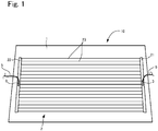
FIG. 1 is a plan view of a glass plate module according to an embodiment of the present invention. -
FIG. 2 is a side view of a connection terminal for use in the glass plate module inFIG. 1 . -
FIG. 3 is a plan view of the connection terminal inFIG. 2 . -
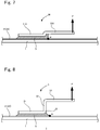
FIG. 4 is a side view illustrating a method for attaching the connection terminal shown inFIG. 2 to a glass plate. -
FIG. 5 is a side view illustrating the method for attaching the connection terminal shown inFIG. 2 to the glass plate. -
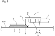
FIG. 6 is an enlarged side view of the glass plate module inFIG. 1 . -
FIG. 7 is a diagram for describing a mechanism that works when a load is applied to a connection terminal according to a comparative example. -
FIG. 8 is a diagram for describing a mechanism that works when a load is applied to the connection terminal according toFIG. 6 . -
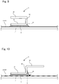
FIG. 9 is a reference diagram showing another example with a structure different from that of the present invention. -
FIG. 10 is a side view showing another example of the glass plate module according to the present invention. -
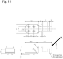
FIG. 11 shows diagrams according to an example. -
FIG. 12 shows diagrams according to Comparative Example 1. -
FIG. 13 shows diagrams according to Comparative Example 2. -
FIG. 14 is a photograph showing Comparative Example 1. -
FIG. 15 is a photograph showing Comparative Example 2. -
FIG. 16 is a photograph showing the example according to the present invention. - An embodiment of a glass plate module according to the present invention will be described below with reference to the drawings.
FIG. 1 is a plan view of this glass plate module. As shown inFIG. 1 , this glass plate module is to be fitted in a window frame of an automobile. Specifically, thisglass plate module 10 has aglass plate 1, a defogger 2 (an electrically conductive layer) laminated on thisglass plate 1, and a pair ofconnection terminals 3 that are attached to thisdefogger 2 using lead-free solder 4.Cables 5 for supplying electric power are respectively attached to theconnection terminals 3, thecables 5 extending from inside the automobile, and an electric current supplied from thecables 5 is supplied to the defogger via theconnection terminals 3. The constituent members will be described below. - A known automotive glass plate can be used as the
glass plate 1. For example, heat absorbing glass, regular clear glass or green glass, or UV green glass may be used as theglass plate 1. However, theglass plate 1 as described above is required to attain visible light transmittance that conforms to the safety standards of the country in which the automobile is to be used. For example, an adjustment can be made such that solar absorptance, visible light transmittance, and the like satisfy the safety standards. An example of the composition of clear glass and an example of the composition of heat absorbing glass are shown below. -
- SiO2: 70 to 73 mass%
- Al2O3: 0.6 to 2.4 mass%
- CaO: 7 to 12 mass%
- MgO: 1.0 to 4.5 mass%
- R2O: 13 to 15 mass% (R is an alkali metal)
- Total iron oxide (T-Fe2O3) in terms of Fe2O3: 0.08 to 0.14 mass%
- With regard to the composition of heat absorbing glass, a composition obtained based on the composition of clear glass by setting the ratio of the total iron oxide (T-Fe2O3) in terms of Fe2O3 to 0.4 to 1.3 mass%, the ratio of CeO2 to 0 to 2 mass%, and the ratio of TiO2 to 0 to 0.5 mass% and reducing the components (mainly SiO2 and Al2O3) forming the framework of glass by an amount corresponding to the increases in T-Fe2O3, CeO2, and TiO2 can be used, for example.
- Note that the type of the
glass plate 1 is not limited to clear glass or heat absorbing glass, and can be selected as appropriate according to the embodiment. For example, theglass plate 1 may be a resin window made of acrylic resin, polycarbonate resin, or the like. - In addition, the thickness of the
glass plate 1 according to this embodiment does not have to be limited particularly. However, from the viewpoint of weight reduction, the thickness of theglass plate 1 may be set in a range of 2.2 to 5.1 mm, a range of 2.4 to 3.8 mm, and a range of 2.7 to 3.2 mm. Furthermore, the thickness of theglass plate 1 may be set to be 3.1 mm or smaller. - In addition, the
glass plate 1 as described above may be laminated glass having an interlayer made of resin or the like sandwiched by a plurality of glass plates, instead of being a single glass plate. - Next, the
defogger 2 will be described. As shown inFIG. 1 , thedefogger 2 has a pair of afirst busbar 21 and asecond busbar 22 for supplying electric power, which extend in the up-down direction along two side edges of theglass plate 1. A plurality ofhorizontal elements 23 are arranged in parallel at a predetermined interval between thebusbars - In addition, an electric current is supplied from the
connection terminal 3 that is attached to thefirst busbar 21, and the connection terminal that is attached to thesecond busbar 22 is grounded via thecable 5. Due to this configuration, when an electric current is supplied to thedefogger 2, defogging heat is generated in thehorizontal elements 23. Note that thebusbars horizontal elements 23 are formed by printing electroconductive silver paste onto the surface of theglass plate 1 and firing the silver paste, for example. However, the material of thedefogger 2 is not limited to this silver paste, and can be selected as appropriate. - Next, the connection terminals will be described with reference to
FIGS. 2 and 3. FIG. 2 is a side view of a connection terminal, andFIG. 3 is a plan view of the connection terminal. For convenience of description, description will be given below based on the directions shown inFIG. 2 . Specifically, description will be given with the up-down direction inFIG. 2 being referred to as the up-down direction, the right-left direction inFIG. 2 being referred to as the front-rear direction, and the up-down direction inFIG. 3 being referred to as the right-left direction or the width direction. - As shown in
FIGS. 2 and 3 , eachconnection terminal 3 according to this embodiment is formed integrally by folding an electrically conductive material such as a metal plate, and includes a single, plate-shapedinstallation portion 31 that is installed on thebusbar defogger 2. Theinstallation portion 31 is formed in a rectangular overall shape, but a front end side thereof is formed in a circular-arc shape. A lower surface of theinstallation portion 31 is fixed to thebusbar free solder 4. - A plate-shaped standing
portion 32 that extends upward is integrally coupled to a rear end portion of theinstallation portion 31. The standingportion 32 is formed in a rectangular shape, and stands at an angle of about 90 degrees to theinstallation portion 31. Note that although the angle α that the standingportion 32 forms with theinstallation portion 31 is not limited to a specific angle, the angle α is preferably 80 to 150 degrees and more preferably 80 to 120 degrees. Setting the angle α at not less than 80 degrees as described above can prevent the lead-free solder 4 from moving from theinstallation portion 31 to theconnection portion 32 against gravity, as will be described later. On the other hand, setting the angle α at not more than 150 degrees can secure the ease of operation during heating of the lead-free solder 4 as will be described later. - In addition, a plate-shaped
connection portion 33 that horizontally extends rearward is integrally coupled to an upper end portion of the standingportion 32. Theconnection portion 33 is formed in a rectangular shape in plan view, and a pair of holdingportions 34 extending downward are integrally coupled to the right and left sides, respectively, of theconnection portion 33. Here, the distance L from the lower surface of theinstallation portion 31 to a lower surface of theconnection portion 33 in the normal direction with respect to theglass plate 1 is preferably 2 mm or more, more preferably 2.5 mm or more, and even more preferably 3 mm or more. The purpose of this is to prevent the lead-free solder 4 from moving from theinstallation portion 31 to theconnection portion 32 against gravity, as will be described later, by setting the distance L at 2 mm or more. - Moreover, each holding
portion 34 includes afirst holding piece 341 that is disposed on a rear end side of theconnection portion 33 and asecond holding piece 342 that is shorter in downward length than thefirst holding piece 341 and is disposed on a front end side. In this manner, the two holdingportions 34 are disposed on theconnection portion 33 such that these holdingportions 34 are nearer to the rear end side than theinstallation portion 31. In addition, thecable 5 is fixed to the holdingportions 34 by disposing thecable 5 between the two holdingportions 34 and crimping the two holdingportions 34 onto thecable 5, as will be described later. - Next, the lead-
free solder 4 that is applied to theinstallation portion 31 of theconnection terminal 3 will be described. For example, the lead-free solder 4 whose Sn content is 90% or more is hard and may crack when joined to a laminated glass plate. Even in such a case, soft lead-free solder 4 such as indium solder and bismuth solder can be used for the joining. - Next, a method for attaching each connection terminal will be described with reference to
FIGS. 4 to 6 . First, as shown inFIG. 4 , thecable 5 is disposed between the two holdingportions 34, and thecable 5 is fixed to the lower surface side of theconnection portion 33 by crimping the holdingportions 34 onto thecable 5. Note that thecable 5 excluding its connection portion that is connected to the two holdingportions 34 of theconnection terminal 3 is coated with an electrically non-conductive member such as rubber. Subsequently, the lead-free solder 4 is applied to the lower surface of theinstallation portion 31. At this time, as will be described later, the amount of lead-free solder 4 that is applied is such that the lead-free solder 4 is squeezed out past theinstallation portion 31 when attached to thebusbar - Subsequently, the
connection terminal 3 that has been prepared as described above is fixed to thebusbar FIG. 5 , the lead-free solder 4 is placed on thebusbar installation portion 31 of theconnection terminal 3 is heated. Thus, the heat is transmitted to the lead-free solder 4 via theinstallation portion 31, and the lead-free solder 4 is melted. As a result, as shown inFIG. 6 , the lead-free solder 4 spreads out in the surface direction of theglass plate 1 while being squeezed out past theinstallation portion 31. Then, as the lead-free solder 4 solidifies, theinstallation portion 31 is fixed to thebusbar free solder 4 extends past a rear end S of theinstallation portion 31 toward the holdingportions 34 and also has a shape that is flared toward theglass plate 1. That is to say, a rear end A of the lead-free solder 4 that is in contact with thebusbar installation portion 31. - As described above, according to the glass plate module of this embodiment, the following effects can be acquired.
- (1) The lead-
free solder 4 has the property of moving to a higher-temperature portion. When the lead-free solder 4 is melted by heating theconnection terminal 3, the temperature of the standingportion 32 and theconnection portion 33 becomes higher than that of theglass plate 1. Thus, there is a possibility that the lead-free solder 4 will move toward theconnection portion 33 against gravity. In this regard, since theconnection terminal 3 of the above-describedglass plate module 10 has the standingportion 32 between theinstallation portion 31 and theconnection portion 33, the lead-free solder 4 can only move to the middle of the standingportion 32, and therefore can be prevented from reaching theconnection portion 33. Thus, the following effects can be achieved. - For example, as shown in
FIG. 7 , if aconnection terminal 30 without a standing portion is used, the lead-free solder 4 moves from aninstallation portion 310 to the lower surface of aconnection portion 330. That is to say, thebusbar connection portion 33 via the lead-free solder 4. Therefore, if an upward force F is exerted on a rear end portion of theconnection portion 330 in this state, due to the moment of rotation of this force F, stress concentrates on a rear end B of the portion of the lead-free solder 4 that is in contact with thebusbar busbar glass plate 1 will crack at this portion B. In particular, the lead-free solder 4 is hard and is thus more likely to crack than lead-containing solder, for example. - In contrast, in the
connection terminal 3 according to this embodiment, due to the standingportion 32 being provided between theinstallation portion 31 and theconnection portion 33, theconnection portion 33 is not directly coupled to thebusbar free solder 4. Accordingly, when an upward force F is exerted on the rear end portion of theconnection portion 33, stress concentrates on acoupling portion 35 between theinstallation portion 31 and the standingportion 32 due to the moment of rotation of the force F. As a result, concentration of stress on the rear end A of the portion of the lead-free solder 4 that is in contact with thebusbar busbar glass plate 1 can be prevented from cracking at this portion A. In particular, in this embodiment, the rear end A of the portion of the lead-free solder 4 that is in contact with thebusbar coupling portion 35 between theinstallation portion 31 and the standingportion 32, and thus concentration of stress on the rear end A can be further prevented. - Consequently, when an external force is exerted on the
connection portion 33 of theconnection terminal 3, for example, even if the worker or the working tool comes into contact therewith, or thecable 5 is unintentionally pulled, thebusbars glass plate 1 can be prevented from cracking as described above, and theconnection terminal 3 can be prevented from becoming detached from thebusbar - In particular, in the above-described connection terminal, when the distance L from the lower surface of the
installation portion 31 to the lower surface of theconnection portion 33 in the normal direction with respect to theglass plate 1 is set to be 2 mm or more, the lead-free solder is even less likely to move to theconnection portion 33 against gravity, and thus, the occurrence of cracking such as that as described above can be more reliably prevented. In addition, this effect can also be achieved by setting the angle of the standingportion 32 to theinstallation portion 31 to be 80 degrees or more. - (2) In the
connection terminal 3 according to this embodiment, even though the standingportion 32 is provided, the protruding height of theconnection terminal 3 from theglass plate 1 can be suppressed because the cable is held on the lower surface side of theconnection portion 33 by the holdingportions 34. Accordingly, theconnection terminal 3 can be kept from coming into contact with the worker, the working tool, or the like. In addition, since the holdingportions 34 do not protrude from the upper surface of theconnection portion 33, the structure of theconnection terminal 3 can be made more compact. - (3) The
connection portion 33 extends in a direction away from theinstallation portion 31 along the surface direction of theglass plate 1, and does not have a structure, such as the one shown inFIG. 9 , that covers an upper portion of theinstallation portion 31. Thus, when heating theinstallation portion 31 while melting the lead-free solder 4, it is possible to heat theinstallation portion 31 using a soldering iron or the like from above theinstallation portion 31, for example. - One embodiment of the present invention has been described above, but the present invention is not limited to the foregoing embodiment, and various modifications can be made without departing from the gist of the invention. In addition, a plurality of variations described as follows can be combined as appropriate.
- 1. In the foregoing embodiment, when the distance L from the lower surface of the
installation portion 31 to the lower surface of theconnection portion 33 in the normal direction with respect to theglass plate 1 is long, or the angle of the standingportion 32 to theinstallation portion 31 is large, thebusbars portion 32 is provided, and the rear end A of the portion of the lead-free solder 4 that is in contact with thebusbar portion 32 on theconnection portion 33 side. For example, as shown inFIG. 10 , it is sufficient that the lead-free solder 4 does not reach theconnection portion 33, and the lead-free solder 4 may extend from the surface of the standingportion 32 on theconnection portion 33 side toward theglass plate 1. - 2. The shapes of the
installation portion 31, the standingportion 32, and theconnection portion 33 are not limited to specific shapes, and these portions can have various shapes. For example, theconnection portion 33 does not have to be parallel to theglass plate 1, and may intersect with theglass plate 1 at an angle other than a perpendicular angle. In addition, for example, a configuration can also be adopted in which a plurality of protrusions are formed on the lower surface of theinstallation portion 31 to increase the area of contact with the lead-free solder 4. Furthermore, theconnection portion 33 is not necessarily required to extend in the front-rear direction. Instead, a configuration may also be adopted in which theconnection portion 33 extends in the right-left direction (width direction), and thecable 5 is connected thereto from the right or left direction. - 3. In the foregoing embodiment, the
connection portion 33 and thecable 5 are fixed to each other by crimping the holdingportions 34 onto thecable 5; however, the present invention is not limited to this, and various connection methods can be applied. For example, it is possible to attach a connector to a leading end of thecable 5 and fit the connector in theconnection portion 33 or to fix thecable 5 and theconnection portion 33 to each other through soldering or using an electrically conductive adhesive, and these portions can be used as the power supply portion of the present invention. In addition, in the case where there is no limitation on the protruding length of theconnection terminal 3 from theglass plate 1, thecable 5 can also be fixed to the upper surface side of theconnection portion 33. - 4. In the foregoing embodiment, an example was described in which the
connection terminal 3 is fixed to thedefogger 2, but apart from a defogger, any electrical component to which an electric current is supplied can applied as the electrically conductive layer of the present invention. For example, an antenna may be applied. - 5. In the foregoing embodiment, an example was described in which a glass plate module is mounted to a window frame of an automobile, but the glass plate module according to the present invention can also be applied to a structure other than an automobile, such as a building.
- 6. Moreover, a configuration can also be adopted in which a flux is applied onto the electrically conductive layer, and the
connection terminal 3 is fixed thereon via the lead-free solder 4. This configuration makes it possible to easily form a lead-free solder 4 with a flared shape. In this case, for example, Gammalux (manufactured by Senju Metal Industry Co., Ltd.) can be used as the flux. - An example of the present invention will be described below. However, the present invention is not limited to the following example.
- A connection terminal having the same form as that of the above-described embodiment was produced as an example. Specifically, a connection terminal shown in
FIG. 11 was produced. The material of the connection terminal was copper, and the dimensions of the connection terminal were as shown inFIG. 11 (the unit is mm). On the other hand, a connection terminal shown inFIG. 12 was produced as Comparative Example 1, and a connection terminal shown inFIG. 13 was produced as Comparative Example 2. The main difference from the example was that the connection terminals of the comparative examples were not provided with a standing portion. - Subsequently, the installation portions of the example and Comparative Examples 1 and 2 configured as described above were fixed onto an electrically conductive layer (whose material was Ag) laminated on a glass plate (air-quench tempered glass plate: the thickness 3.1 mm) using lead-free solder (Sn: 96.5% and Ag: 3.5%). Then, the example and Comparative Examples 1 and 2 were stored for 500 hours in a storage chamber at a temperature of 80 °C and 95% humidity.
- Next, six each of the connection terminals of the example and Comparative Examples 1 and 2 configured as described above were prepared, and a bond strength test was performed on them. Specifically, an upward force was exerted on portions indicated by arrows K in
FIGS. 11 to 13 , and the occurrence of cracking in the electrically conductive layer or the glass plate was checked. The upward force was gradually increased from 0 up to 78.4 N. The force (in N) at the time when the glass plate cracked was measured. Table 1 below shows the results.Table 1 1 2 3 4 5 6 Average Ex. - - - - - - - Com. Ex. 1 30.1 25.0 27.5 25.7 54.6 46.9 35.0 Com. Ex. 2 25.6 35.8 34.0 42.7 51.4 35.6 37.5 - In Comparative Examples 1 and 2, with respect to all of the samples, the glass plate or the electrically conductive layer cracked prior to the exerted force reaching 78.4 N. On the other hand, in the example, neither the glass plate nor the electrically conductive layer cracked even when the exerted force reached 78.4 N.
- Here, photographs showing the examples and Comparative Examples 1 and 2 are examined. With respect to Comparative Example 1 shown in
FIG. 14 , the lead-free solder moved to a portion indicated by the arrow inFIG. 14 , that is, the lower surface of the connection portion, and it can be found that the electrically conductive layer and the connection portion were connected to each other by the lead-free solder. Similarly, with respect to Comparative Example 2 shown inFIG. 15 as well, the lead-free solder moved to the lower surface of the connection portion indicated by the arrow inFIG. 15 . On the other hand, with respect to the example shown inFIG. 16 , the lead-free solder reached only the vicinity of a lower end portion of the standing portion, and the lead-free solder extended rearward from the rear end portion of the installation portion in a flared manner. Therefore, it can be considered that in Comparative Examples 1 and 2, the upward force even acted on the electrically conductive layer or the glass plate via the connection portion and the lead-free solder and caused cracking. On the other hand, with regard to the example, it can be considered that since the connection portion and the electrically conductive layer were not connected to each other via the lead-free solder, and the lead-free solder extended rearward from the rear end portion of the installation portion in a flared manner, cracking did not occur. -
- 1: Glass plate
- 2: Defogger (electrically conductive layer)
- 3: Connection terminal
- 4: Lead-free solder
- 5: Cable
- 10: Glass plate module
- 31: Installation portion
- 32: Standing portion
- 33: Connection portion
- 34: Holding portion
Claims (5)
- A glass plate module comprising:a glass plate;an electrically conductive layer laminated on the glass plate;at least one connection terminal fixed to the electrically conductive layer and made of an electrically conductive material; andlead-free solder for fixing the connection terminal to the electrically conductive layer,wherein the connection terminal includes:an installation portion that is fixed to the electrically conductive layer via the lead-free solder;a standing portion that extends from an end portion of the installation portion in a direction away from the glass plate; anda connection portion that is coupled to an end portion of the standing portion on the opposite side to the installation portion and extends in a direction away from the installation portion along a surface direction of the glass plate,the connection portion has a power supply portion to which a cable for supplying electric power to the electrically conductive layer is connected, the power supply portion being located at a position that is spaced apart from the installation portion in the surface direction of the glass plate, andthe lead-free solder has a shape such that the nearer to the electrically conductive layer from a surface of the standing portion on the connection portion side, the further the lead-free solder extends to the power supply portion side.
- The glass plate module according to claim 1,
wherein a length of the standing portion between a surface of the installation portion that faces the electrically conductive layer and a surface of the connection portion that faces the electrically conductive layer is 2 mm or more. - The glass plate module according to claim 1 or 2,
wherein the standing portion stands at an angle of 80 degrees or more to the installation portion. - The glass plate module according to any one of claims 1 to 3,
wherein the power supply portion includes a holding portion that holds the cable, the holding portion being located on a surface of the connection portion that faces the electrically conductive layer. - The glass plate module according to claim 4,
wherein the holding portion is configured to hold the cable by being crimped onto the cable.
Applications Claiming Priority (2)
| Application Number | Priority Date | Filing Date | Title |
|---|---|---|---|
| JP2015140378A JP6725971B2 (en) | 2015-07-14 | 2015-07-14 | Glass plate module |
| PCT/JP2016/070621 WO2017010493A1 (en) | 2015-07-14 | 2016-07-12 | Glass plate module |
Publications (2)
| Publication Number | Publication Date |
|---|---|
| EP3324486A1 true EP3324486A1 (en) | 2018-05-23 |
| EP3324486A4 EP3324486A4 (en) | 2019-04-03 |
Family
ID=57758144
Family Applications (1)
| Application Number | Title | Priority Date | Filing Date |
|---|---|---|---|
| EP16824473.9A Pending EP3324486A4 (en) | 2015-07-14 | 2016-07-12 | Glass plate module |
Country Status (5)
| Country | Link |
|---|---|
| US (1) | US11225059B2 (en) |
| EP (1) | EP3324486A4 (en) |
| JP (1) | JP6725971B2 (en) |
| CN (1) | CN107925170B (en) |
| WO (1) | WO2017010493A1 (en) |
Cited By (2)
| Publication number | Priority date | Publication date | Assignee | Title |
|---|---|---|---|---|
| CN113412173A (en) * | 2019-02-08 | 2021-09-17 | 日本板硝子株式会社 | Glass panel assembly |
| EP3993165A4 (en) * | 2019-07-01 | 2023-07-19 | Nippon Sheet Glass Company, Limited | Connection terminal |
Families Citing this family (6)
| Publication number | Priority date | Publication date | Assignee | Title |
|---|---|---|---|---|
| DK2708093T3 (en) * | 2011-05-10 | 2020-02-24 | Saint Gobain | WINDOW WITH AN ELECTRIC CONNECTOR |
| GB201804622D0 (en) | 2018-03-22 | 2018-05-09 | Central Glass Co Ltd | Method of producing a vehicle glass assembly |
| CN112219317B (en) * | 2018-06-05 | 2022-09-13 | Agc株式会社 | Vehicle window glass with terminal |
| CN109038008B (en) * | 2018-07-25 | 2020-04-28 | 武汉华尚绿能科技股份有限公司 | Glass curtain wall circuit glass plate connector |
| JP2020061277A (en) * | 2018-10-10 | 2020-04-16 | Agc株式会社 | Vehicular window glass with terminal |
| JP7274279B2 (en) * | 2018-11-05 | 2023-05-16 | Agc株式会社 | METHOD FOR MANUFACTURING GLASS PLATE WITH METAL TERMINAL |
Family Cites Families (18)
| Publication number | Priority date | Publication date | Assignee | Title |
|---|---|---|---|---|
| JPS62160465U (en) * | 1986-04-01 | 1987-10-12 | ||
| JPH033260A (en) * | 1989-05-30 | 1991-01-09 | Yamaha Corp | Lead terminal of package for integrated circuit |
| JP2599416Y2 (en) * | 1992-06-22 | 1999-09-06 | セントラル硝子株式会社 | Conductive terminal mounting structure for anti-fog glass |
| ATE400481T1 (en) * | 2002-03-11 | 2008-07-15 | Nippon Sheet Glass Co Ltd | GLASS ARTICLES CONNECTED BY A METAL FASTENER AND CONNECTION CONSTRUCTION USING SAME |
| US20070224842A1 (en) * | 2004-11-12 | 2007-09-27 | Agc Automotive Americas R&D, Inc. | Electrical Connector For A Window Pane Of A Vehicle |
| GB0605884D0 (en) * | 2006-03-24 | 2006-05-03 | Pilkington Plc | Electrical connector |
| JP2010123693A (en) * | 2008-11-18 | 2010-06-03 | Fujitsu Ten Ltd | Terminal structure |
| EP2408260A1 (en) * | 2010-07-13 | 2012-01-18 | Saint-Gobain Glass France | Glass pane with electric connection element |
| EP2670560B1 (en) * | 2011-02-04 | 2016-01-13 | Antaya Technologies Corp. | Lead-free solder composition |
| DE202011100906U1 (en) * | 2011-05-03 | 2011-06-09 | FEW Fahrzeugelektrikwerk GmbH & Co. KG, 04442 | Electrical connection element |
| US20140182932A1 (en) * | 2011-05-10 | 2014-07-03 | Saint-Gobain Glass France | Disk having an electric connecting element |
| DK2708093T3 (en) * | 2011-05-10 | 2020-02-24 | Saint Gobain | WINDOW WITH AN ELECTRIC CONNECTOR |
| BR112015005078A2 (en) * | 2012-09-14 | 2017-07-04 | Saint Gobain | plate with electrical connection element |
| JP6044227B2 (en) * | 2012-09-26 | 2016-12-14 | 日本電気株式会社 | Hermetic sealing package and manufacturing method thereof |
| CA2891680C (en) * | 2012-11-21 | 2018-06-05 | Saint-Gobain Glass France | Pane with electrical connection element and compensator plates |
| JP6210820B2 (en) * | 2013-09-30 | 2017-10-11 | 日本板硝子株式会社 | Terminal structure and glass body for vehicle |
| AR097558A1 (en) | 2013-10-29 | 2016-03-23 | Saint Gobain | ENTREPAÑO WITH - AT LEAST - TWO ELEMENTS OF ELECTRICAL CONNECTION AND A CONNECTOR |
| JP6680481B2 (en) * | 2015-07-22 | 2020-04-15 | 日本板硝子株式会社 | Glass plate module |
-
2015
- 2015-07-14 JP JP2015140378A patent/JP6725971B2/en active Active
-
2016
- 2016-07-12 WO PCT/JP2016/070621 patent/WO2017010493A1/en active Application Filing
- 2016-07-12 US US15/744,290 patent/US11225059B2/en active Active
- 2016-07-12 CN CN201680040995.1A patent/CN107925170B/en active Active
- 2016-07-12 EP EP16824473.9A patent/EP3324486A4/en active Pending
Cited By (3)
| Publication number | Priority date | Publication date | Assignee | Title |
|---|---|---|---|---|
| CN113412173A (en) * | 2019-02-08 | 2021-09-17 | 日本板硝子株式会社 | Glass panel assembly |
| CN113412173B (en) * | 2019-02-08 | 2023-02-17 | 日本板硝子株式会社 | Glass panel assembly |
| EP3993165A4 (en) * | 2019-07-01 | 2023-07-19 | Nippon Sheet Glass Company, Limited | Connection terminal |
Also Published As
| Publication number | Publication date |
|---|---|
| CN107925170B (en) | 2021-01-12 |
| WO2017010493A1 (en) | 2017-01-19 |
| CN107925170A (en) | 2018-04-17 |
| US11225059B2 (en) | 2022-01-18 |
| EP3324486A4 (en) | 2019-04-03 |
| JP2017022047A (en) | 2017-01-26 |
| US20180200997A1 (en) | 2018-07-19 |
| JP6725971B2 (en) | 2020-07-22 |
Similar Documents
| Publication | Publication Date | Title |
|---|---|---|
| US11225059B2 (en) | Glass plate module | |
| EP3327866A1 (en) | Glass plate module | |
| EP2664503B1 (en) | A method for producing a windowpane for vehicles | |
| US20090277671A1 (en) | Glass pane having soldered electrical terminal connections | |
| US10843662B2 (en) | Glass plate module | |
| CN101443960A (en) | Electrical connector | |
| CN111344903B (en) | Glazing assembly for vehicle windows | |
| US20170312859A1 (en) | Window glass structure for vehicle | |
| EP3922392A1 (en) | Glass plate module | |
| EP3993165A1 (en) | Connection terminal | |
| WO2023276997A1 (en) | Vehicle glass module | |
| JP2020074303A (en) | Glass plate module | |
| US20240140361A1 (en) | Vehicle window glass |
Legal Events
| Date | Code | Title | Description |
|---|---|---|---|
| STAA | Information on the status of an ep patent application or granted ep patent |
Free format text: STATUS: THE INTERNATIONAL PUBLICATION HAS BEEN MADE |
|
| PUAI | Public reference made under article 153(3) epc to a published international application that has entered the european phase |
Free format text: ORIGINAL CODE: 0009012 |
|
| STAA | Information on the status of an ep patent application or granted ep patent |
Free format text: STATUS: REQUEST FOR EXAMINATION WAS MADE |
|
| 17P | Request for examination filed |
Effective date: 20180209 |
|
| AK | Designated contracting states |
Kind code of ref document: A1 Designated state(s): AL AT BE BG CH CY CZ DE DK EE ES FI FR GB GR HR HU IE IS IT LI LT LU LV MC MK MT NL NO PL PT RO RS SE SI SK SM TR |
|
| AX | Request for extension of the european patent |
Extension state: BA ME |
|
| DAV | Request for validation of the european patent (deleted) | ||
| DAX | Request for extension of the european patent (deleted) | ||
| A4 | Supplementary search report drawn up and despatched |
Effective date: 20190306 |
|
| RIC1 | Information provided on ipc code assigned before grant |
Ipc: B32B 17/10 20060101ALI20190227BHEP Ipc: H05B 3/84 20060101AFI20190227BHEP Ipc: H01R 4/02 20060101ALI20190227BHEP Ipc: H01R 12/57 20110101ALI20190227BHEP Ipc: H05K 1/18 20060101ALI20190227BHEP |
|
| STAA | Information on the status of an ep patent application or granted ep patent |
Free format text: STATUS: EXAMINATION IS IN PROGRESS |
|
| 17Q | First examination report despatched |
Effective date: 20201126 |
|
| STAA | Information on the status of an ep patent application or granted ep patent |
Free format text: STATUS: EXAMINATION IS IN PROGRESS |