EP3324459A1 - Abdeckungsstruktur einer leistungsbatterie sowie leistungsbatterie - Google Patents
Abdeckungsstruktur einer leistungsbatterie sowie leistungsbatterie Download PDFInfo
- Publication number
- EP3324459A1 EP3324459A1 EP17000575.5A EP17000575A EP3324459A1 EP 3324459 A1 EP3324459 A1 EP 3324459A1 EP 17000575 A EP17000575 A EP 17000575A EP 3324459 A1 EP3324459 A1 EP 3324459A1
- Authority
- EP
- European Patent Office
- Prior art keywords
- resistance
- top cover
- short circuit
- circuit component
- power battery
- Prior art date
- Legal status (The legal status is an assumption and is not a legal conclusion. Google has not performed a legal analysis and makes no representation as to the accuracy of the status listed.)
- Granted
Links
- 230000000694 effects Effects 0.000 claims abstract description 16
- 239000000463 material Substances 0.000 claims description 10
- 238000004146 energy storage Methods 0.000 abstract description 3
- 239000010410 layer Substances 0.000 description 36
- 238000010586 diagram Methods 0.000 description 17
- 229920006362 Teflon® Polymers 0.000 description 3
- 230000017525 heat dissipation Effects 0.000 description 3
- 238000000034 method Methods 0.000 description 3
- XAGFODPZIPBFFR-UHFFFAOYSA-N aluminium Chemical compound [Al] XAGFODPZIPBFFR-UHFFFAOYSA-N 0.000 description 2
- 239000003792 electrolyte Substances 0.000 description 2
- 238000004880 explosion Methods 0.000 description 2
- 238000012986 modification Methods 0.000 description 2
- 230000004048 modification Effects 0.000 description 2
- 239000004033 plastic Substances 0.000 description 2
- 238000005507 spraying Methods 0.000 description 2
- 229910052782 aluminium Inorganic materials 0.000 description 1
- 230000009286 beneficial effect Effects 0.000 description 1
- 238000005520 cutting process Methods 0.000 description 1
- 238000000354 decomposition reaction Methods 0.000 description 1
- 239000002360 explosive Substances 0.000 description 1
- 230000020169 heat generation Effects 0.000 description 1
- 239000011810 insulating material Substances 0.000 description 1
- 238000004519 manufacturing process Methods 0.000 description 1
- 239000007769 metal material Substances 0.000 description 1
- 239000002344 surface layer Substances 0.000 description 1
- 238000003466 welding Methods 0.000 description 1
- 238000004804 winding Methods 0.000 description 1
Images


Classifications
-
- H—ELECTRICITY
- H01—ELECTRIC ELEMENTS
- H01M—PROCESSES OR MEANS, e.g. BATTERIES, FOR THE DIRECT CONVERSION OF CHEMICAL ENERGY INTO ELECTRICAL ENERGY
- H01M50/00—Constructional details or processes of manufacture of the non-active parts of electrochemical cells other than fuel cells, e.g. hybrid cells
- H01M50/50—Current conducting connections for cells or batteries
- H01M50/572—Means for preventing undesired use or discharge
- H01M50/574—Devices or arrangements for the interruption of current
- H01M50/578—Devices or arrangements for the interruption of current in response to pressure
-
- H—ELECTRICITY
- H01—ELECTRIC ELEMENTS
- H01M—PROCESSES OR MEANS, e.g. BATTERIES, FOR THE DIRECT CONVERSION OF CHEMICAL ENERGY INTO ELECTRICAL ENERGY
- H01M50/00—Constructional details or processes of manufacture of the non-active parts of electrochemical cells other than fuel cells, e.g. hybrid cells
- H01M50/10—Primary casings; Jackets or wrappings
- H01M50/147—Lids or covers
-
- H—ELECTRICITY
- H01—ELECTRIC ELEMENTS
- H01M—PROCESSES OR MEANS, e.g. BATTERIES, FOR THE DIRECT CONVERSION OF CHEMICAL ENERGY INTO ELECTRICAL ENERGY
- H01M50/00—Constructional details or processes of manufacture of the non-active parts of electrochemical cells other than fuel cells, e.g. hybrid cells
- H01M50/30—Arrangements for facilitating escape of gases
- H01M50/317—Re-sealable arrangements
- H01M50/325—Re-sealable arrangements comprising deformable valve members, e.g. elastic or flexible valve members
-
- H—ELECTRICITY
- H01—ELECTRIC ELEMENTS
- H01M—PROCESSES OR MEANS, e.g. BATTERIES, FOR THE DIRECT CONVERSION OF CHEMICAL ENERGY INTO ELECTRICAL ENERGY
- H01M50/00—Constructional details or processes of manufacture of the non-active parts of electrochemical cells other than fuel cells, e.g. hybrid cells
- H01M50/50—Current conducting connections for cells or batteries
- H01M50/572—Means for preventing undesired use or discharge
- H01M50/574—Devices or arrangements for the interruption of current
-
- H—ELECTRICITY
- H01—ELECTRIC ELEMENTS
- H01M—PROCESSES OR MEANS, e.g. BATTERIES, FOR THE DIRECT CONVERSION OF CHEMICAL ENERGY INTO ELECTRICAL ENERGY
- H01M50/00—Constructional details or processes of manufacture of the non-active parts of electrochemical cells other than fuel cells, e.g. hybrid cells
- H01M50/50—Current conducting connections for cells or batteries
- H01M50/572—Means for preventing undesired use or discharge
- H01M50/584—Means for preventing undesired use or discharge for preventing incorrect connections inside or outside the batteries
- H01M50/588—Means for preventing undesired use or discharge for preventing incorrect connections inside or outside the batteries outside the batteries, e.g. incorrect connections of terminals or busbars
-
- H—ELECTRICITY
- H01—ELECTRIC ELEMENTS
- H01M—PROCESSES OR MEANS, e.g. BATTERIES, FOR THE DIRECT CONVERSION OF CHEMICAL ENERGY INTO ELECTRICAL ENERGY
- H01M2200/00—Safety devices for primary or secondary batteries
- H01M2200/20—Pressure-sensitive devices
-
- H—ELECTRICITY
- H01—ELECTRIC ELEMENTS
- H01M—PROCESSES OR MEANS, e.g. BATTERIES, FOR THE DIRECT CONVERSION OF CHEMICAL ENERGY INTO ELECTRICAL ENERGY
- H01M2220/00—Batteries for particular applications
- H01M2220/20—Batteries in motive systems, e.g. vehicle, ship, plane
-
- H—ELECTRICITY
- H01—ELECTRIC ELEMENTS
- H01M—PROCESSES OR MEANS, e.g. BATTERIES, FOR THE DIRECT CONVERSION OF CHEMICAL ENERGY INTO ELECTRICAL ENERGY
- H01M50/00—Constructional details or processes of manufacture of the non-active parts of electrochemical cells other than fuel cells, e.g. hybrid cells
- H01M50/50—Current conducting connections for cells or batteries
- H01M50/543—Terminals
- H01M50/547—Terminals characterised by the disposition of the terminals on the cells
- H01M50/55—Terminals characterised by the disposition of the terminals on the cells on the same side of the cell
-
- H—ELECTRICITY
- H01—ELECTRIC ELEMENTS
- H01M—PROCESSES OR MEANS, e.g. BATTERIES, FOR THE DIRECT CONVERSION OF CHEMICAL ENERGY INTO ELECTRICAL ENERGY
- H01M50/00—Constructional details or processes of manufacture of the non-active parts of electrochemical cells other than fuel cells, e.g. hybrid cells
- H01M50/50—Current conducting connections for cells or batteries
- H01M50/543—Terminals
- H01M50/552—Terminals characterised by their shape
- H01M50/553—Terminals adapted for prismatic, pouch or rectangular cells
-
- Y—GENERAL TAGGING OF NEW TECHNOLOGICAL DEVELOPMENTS; GENERAL TAGGING OF CROSS-SECTIONAL TECHNOLOGIES SPANNING OVER SEVERAL SECTIONS OF THE IPC; TECHNICAL SUBJECTS COVERED BY FORMER USPC CROSS-REFERENCE ART COLLECTIONS [XRACs] AND DIGESTS
- Y02—TECHNOLOGIES OR APPLICATIONS FOR MITIGATION OR ADAPTATION AGAINST CLIMATE CHANGE
- Y02E—REDUCTION OF GREENHOUSE GAS [GHG] EMISSIONS, RELATED TO ENERGY GENERATION, TRANSMISSION OR DISTRIBUTION
- Y02E60/00—Enabling technologies; Technologies with a potential or indirect contribution to GHG emissions mitigation
- Y02E60/10—Energy storage using batteries
Definitions
- the present application relates to the field of energy storage devices and, particularly, relates to a top cover structure for a power battery and a power battery.
- Electric vehicle and energy storage power station usually need power battery having large capacity as the power source. Except large capacity, the power battery should also perform better safety and have a longer cycle life, so as to meet application standards and satisfy people's requirements.
- the positive electrode and the negative electrode are connected to form a short circuit, since the resistance in the loop is so small that the current in the loop will be too large (such as, exceeding 10000A), the short circuit component is easy to be fused, thus the short circuit component is fused before the connecting component is fused, which leads to that the loop current cannot maintain, then the connecting component cannot be fused; but if the resistance in the loop is too large, which will cause that the current in the loop is too small (such as, less than 500A), the connecting component will not be fused, which cannot prevent the power battery from being charged continuously. Therefore, when dealing with over-charging of the power battery, it is obvious that the manner of directly connecting a large resistance is not applicable to reduce current.
- the top cover structure of the power battery is needed to be re-optimized, so that the power battery can constitute a loop having an appropriate resistance value under the situations of over-charging and nailing.
- the present application provides a top cover structure for a power battery and a power battery, which can solve the above problems.
- a first aspect of the present application provides a top cover structure for a power battery, including a first electrode assembly, a second electrode assembly, a first resistance, a second resistance, a top cover plate, a first short circuit component and a second short circuit component, the first electrode assembly is electrically connected with the top cover plate through the first resistance for all time, the second electrode assembly is insulated from the top cover plate in a normal state, the first short circuit component and the second short circuit component are both attached onto the top cover plate, when an internal pressure of the power battery exceeds a reference pressure, both the first short circuit component and the second short circuit component deform by effect of pressure, so as to form a first electrical connecting path through the first electrode assembly, the first short circuit component, the top cover plate, the second short circuit component and the second electrode assembly in sequence, and to form a second electrical connecting path through the first electrode assembly, the first resistance, the top cover plate, the second short circuit component and the second electrode assembly in sequence, the second resistance is connected into the first electrical connecting path in series; a resistance value of the first resistance
- the first resistance is connected with the second resistance in series for all time.
- the second resistance is either integrated or arranged into the first electrode assembly; the first short circuit component is electrically connected with the first electrode assembly through the top cover plate, the first resistance and the second resistance for all time.
- the first electrode assembly includes a first electrode terminal and a first conductive plate, the first electrode terminal passes through the top cover plate, the first conductive plate includes a first connecting portion and a first extending portion which are connected with each other, the second resistance is connected between the first connecting portion and the first electrode terminal in series, the first short circuit component contacts with the first extending portion after deforming by effect of pressure; either the first resistance is connected between the second resistance and the top cover plate in series, or the first resistance is connected between the first connecting portion and the top cover plate in series.
- the second resistance is at least one of forms consisting of:
- the second resistance is integrated onto the first connecting portion
- a structure of the first conductive plate is as follows: the first conductive plate includes a first conductive layer and a second conductive layer, the first conductive layer and the second conductive layer are arranged by stacking, the first conductive layer is configured to contact with the second short circuit component, and a resistivity of the first conductive layer and a resistivity of the second short circuit component are both less than a resistivity of the second conductive layer.
- the second resistance is either integrated or arranged into the second electrode assembly.
- the second electrode assembly includes a second electrode terminal and a second conductive plate, the second electrode terminal passes through the top cover plate, and is connected with and insulated from the top cover plate, the second conductive plate is also connected with and insulated from the top cover plate, the second conductive plate includes a second connecting portion and a second extending portion which are connected with each other, the second short circuit component contacts with the second extending portion after deforming by effect of pressure; either the second resistance is connected between the second connecting portion and the second electrode terminal in series, or the second resistance is connected between the second connecting portion and the second extending portion in series.
- the second extending portion and the second short circuit component adopt a same material.
- the second resistance is at least one of forms consisting of:
- the second resistance is integrated onto the second conductive plate
- a structure of the second conductive plate is as follows:
- the second resistance is connected with the first resistance in parallel.
- the first electrode assembly includes a first electrode terminal and a first conductive plate, the first electrode terminal passes through the top cover plate, the first conductive plate includes a first connecting portion and a first extending portion which are connected with each other, the first short circuit component contacts with the first extending portion after deforming by effect of pressure, the second resistance is connected between the first connecting portion and the first extending portion in series; either the first resistance is connected between the first connecting portion and the top cover plate in series, or the first resistance is connected between the first electrode terminal and the top cover plate in series.
- the first extending portion and the first short circuit component adopt a same material.
- the first electrode assembly includes a first electrode terminal and a first conductive plate, the first electrode terminal passes through the top cover plate, the first resistance is connected between the first electrode terminal and the top cover plate in series, the first short circuit component contacts with the first extending portion after deforming by effect of pressure, the second resistance is connected between the first electrode terminal and the first conductive plate in series.
- the first resistance is located underneath the top cover plate, and the second resistance is located above the top cover plate.
- a resistance value of the first resistance is at least 1000 times larger than a resistance value of the second resistance.
- the resistance value of the first resistance is 1 ⁇ 100000 ⁇ , or the resistance value of the second resistance is 0.1 ⁇ 100m ⁇ .
- a second aspect of the present embodiment provides a power battery, including a bare cell and the top cover structure for a power battery,
- the bare cell has two electrodes with opposite electrical properties, one of the electrodes is electrically connected with the first electrode assembly, the other electrode thereof is electrically connected with the second electrode assembly, when an internal pressure of the power battery exceeds a reference pressure, the first short circuit component and the second short circuit component deform by effect of pressure, so as to form a first electrical connecting loop from the bare cell back to the bare cell passing through the first electrical connecting path, and to form a second electrical connecting loop from the bare cell back to the bare cell passing through the second electrical connecting path.
- one of the electrodes is electrically connected with the first electrode assembly through the first connecting piece, the other electrode thereof is electrically connected with the second electrode assembly through the second connecting piece, and a fusing member is formed on the first connecting piece and/or the second connecting piece.
- the fusing member is formed through providing a gap and/or a hole on the first connecting piece and/or the second connecting piece.
- the present application provides a power battery, as shown in FIG. 17 , which includes a top cover structure 1 for a power battery, a bare cell 2, an housing 3, a first connecting piece 4 and a second connecting piece 5, the bare cell 2 is generally formed by a positive electrode plate, a negative electrode plate and a separator through winding or stacking, a positive electrode tab 2a and a negative electrode tab 2b are respectively provided on the positive electrode plate and the negative electrode plate.
- the housing 3 is generally made of metal material, and forms, together with the top cover structure 1 for a power battery, a cavity for accommodating the bare cell 2, the bare cell 2 is arranged in the cavity.
- the top cover structure for a power battery includes a first electrode assembly 10, a second electrode assembly 20, a first resistance 30, a second resistance 40, a top cover plate 50, a first short circuit component 60 and a second short circuit component 70.
- the first electrode assembly 10 and the second electrode assembly 20 are both attached onto the top cover plate 50, and, either the first electrode assembly 10 or the second electrode assembly 20 is connected with the positive electrode tab 2a or the negative electrode tab 2b of the bare cell through a first connecting piece 4, the other electrode assembly is connected with the other electrode tab of the bare cell through a second connecting piece 5.
- a second connecting piece 5 For example, as shown in FIG.
- the first electrode assembly 10 is electrically connected with the positive electrode tab 2a of the bare cell 2 through the first connecting piece 4, at the same time, the second electrode assembly 20 is electrically connected with the negative electrode tab 2b of the bare cell 2 through the second connecting piece 5, so as to extend the positive electrode and the negative electrode of the power battery respectively.
- a fusing member 6 with a gap or of a hole shape is formed on the second connecting piece 5, absolutely, the fusing member 6 can also be arranged on the first connecting piece 4 at the same time or in individual.
- the first electrode assembly 10 includes a first electrode terminal 100, the bottom of the first electrode terminal 100 is located underneath the top cover plate 50, the top of the first electrode terminal 100 will go through the top cover plate 50. It should be noted that, the first electrode terminal 100 cannot contact and be electrically connected with the top cover plate 50 directly, but be fixed with a first insulating piece 102 therebetween, in addition, the first electrode terminal 100 needs to keep an electrical connection with the top cover plate 50 through the first resistance 30.
- the first electrode terminal 100 can also be designed to be two parts including a first electrode terminal body 100a and a first connecting block 100b, the first electrode terminal body 100a extends through the top cover plate 50, and the first connecting block 100b can be fixed with the top of the first electrode terminal body 100a through a welding or riveting manner, so as to increase contacting area and improve structure of the contacting surface, thereby providing a better connection.
- the first short circuit component 60 and the second short circuit component 70 are two important circuit switches, when the first short circuit component 60 is not deforming, the circuit structure of the top cover structure 1 for a power battery is a nailing protection circuit, when nailing occurs, the nailing protection circuit can be functioned effectively; however, when the first short circuit component 60 and the second short circuit component 70 are connected with the circuit at the same time, the circuit structure of the top cover structure 1 for a power battery will be transformed to an over-charging protection circuit, so as to generate an appropriate circuit to fuse the first connecting piece 4 and/or the second connecting piece 5 near by the fusing member 6, thereby cutting off the electrical connection between the positive electrode tab 2a and the first electrode assembly 10, and/or the electrical connection between the negative electrode tab 2b and the second electrode assembly 20.
- the top cover for a power battery has limited space, particularly near the two electrodes because of a plurality of connecting pieces and insulating pieces are needed to be arranged, thereby it is very crowded, in this situation, arranging the first short circuit component 60 thereon also requires better structure design and processing technique.
- first electrode assembly 10 of the present embodiment is further provided with a first conductive plate 104 in the interior thereof, the first conductive plate 104 includes a first connecting portion 104a and a first extending portion 104b which are connected with each other, the first connecting portion 104a is configured to be electrically connected with the first electrode terminal body 100a or the first connecting block 100b of the first electrode terminal 100, and the first extending portion 104b extends outward for a certain distance, at the same time, the first conductive plate 104 is fixed with the top cover plate 50 through the first insulating piece 102.
- the first short circuit component 60 generally adopts a deformable plate form, absolutely, other components which can deform when the internal pressure of the power battery is increasing can also be adopted.
- the top cover plate 50 is provided with a first mounting hole 500 at a location having a certain distance from the first electrode terminal 100, the first short circuit component 60 is assembled in the first mounting hole 500 and seals the first mounting hole 500, the first extending portion 104b extends above the first mounting hole 500.
- the first short circuit component 60 can contact the first extending portion 104b and achieve an electrical connection after deforming upward.
- the structure of the second electrode assembly 20 can be same as the first electrode assembly 10, also can be different.
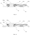
- the second electrode assembly 20 can also adopt a structure similar to the first electrode assembly 10, specifically including a second electrode terminal 200, a second insulating piece 202 and a second conductive plate, the second electrode terminal 200 includes a second electrode terminal body 200a and a second connecting block 200b, the second electrode terminal body 200a extends through the top cover plate 50 and is connected with the second connecting block 200b. As shown from FIG. 11 to FIG.
- the second conductive plate 204 includes a second connecting portion 204a and a second extending portion 204b which are connected with each other, the second connecting portion 204a is configured to be electrically connected with the second electrode terminal body 200a or the second connecting block 200b of the second electrode terminal 200, the second extending portion 204b extends outward for a certain distance.
- the top cover plate 50 is provided with a second mounting hole 502 at a location having a certain distance from the second electrode terminal 200, the second short circuit component 70 is assembled in the second mounting hole 502 and seals the second mounting hole 502, the second extending portion 204b extends above the second mounting hole 502.
- the second short circuit component 70 can contact the second extending portion 204b and achieve an electrical connection after deforming upward.
- the second electrode assembly 20 is connected with the top cover plate 50 only through the second insulating piece 202 in a general situation, and thus is insulated.
- the first short circuit component 60 will contact with the first conductive plate 104 after deforming, if the difference of resistivity at the contacting position of the first short circuit component 60 and the first conductive plate 104 is relatively large, then the first short circuit component 60 may be fused directly, however, this situation can be effectively avoided if the resistivity therebetween are similar at the contacting position. Therefore, on the first conductive plate 104, at least the material of the first extending portion 104b is the same as the first short circuit component 60, aluminum metal is recommended in practical production. Similarly, on the second conductive plate 204, at least the material of the second extending portion 204b is the same as the second short circuit component 70.
- the positive electrode tab 2a of the bare cell is needed to be connected with the top cover plate 50 and the housing 3 all the time, so that the top cover plate 50 and the housing 3 is positively charged.
- first electrode assembly 10 is connected with the positive electrode tab 2a
- second electrode assembly 20 is connected with the negative electrode tab 2b as an example
- the first electrode terminal 100 is electrically connected with the top cover plate 50 through the first resistance 30 all the time, so that the top cover plate 50 is positively charged for all time.
- the nail When nailing occurs, and the pressure in the housing is not sufficient to make the first short circuit component 60 deform, the nail will make the negative electrode plate in the power battery be connected with the housing and the top cover plate 50, the top cover plate 50 is connected with the first electrode terminal 100 of the first electrode assembly 10 through a first resistance 30, and then finally connected with the positive electrode plate in the interior of the bare cell through the positive electrode tab 2a, so as to form a nailing loop.
- the resistance value of the first resistance 30 is generally 1 ⁇ 100000 ⁇ . In the nailing loop, the existence of the first resistance 30 can effectively reduce the current in the nailing loop, and effectively prevent the situation that since the current is too large, causing sparking at the nailing point, igniting the electrolyte, and result in burning of the power battery.
- the first resistance 30 can adopt a resistance block (referring to FIGs. 4 , 8 , 9, 10 ), conductive plastic (referring to FIGs. 5-7 ) and the like, when adopting conductive plastic, the first resistance 30 can replace or partially replace the first insulating piece 102.
- the circuit When over-charging occurs, since the circuit needs to generate a larger current to fuse the fusing member 6, but the resistance value of the first resistance 30 is too large, therefore, it should be prevented that the first resistance 30 is directly connected with the circuit in series in the over-charging protection circuit.
- a second resistance 40 is needed to be connected into the circuit, the resistance value of the second resistance 40 cannot be too large, generally cannot exceed 1/1000 of the resistance value of the first resistance 30, the range of 0.1 ⁇ 100m ⁇ is preferred.
- the present embodiment takes a careful consideration on the arrangement location of the first resistance 30 and the second resistance 40, which will be described in detail below.
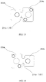
- a low resistance branch and a high resistance branch can be formed, and the first resistance 30 is located in the high resistance branch, so as to decrease the resistance value of the whole over-charging protection circuit.
- the first resistance 30 at least has two connection structures as follows:
- the first short circuit component 60 and the second short circuit component 70 will deform by effect of pressure. Specifically, the first short circuit component 60 and the second short circuit component 70 may deform at the same time, or respectively deforms one after another. After the first short circuit component 60 and the second short circuit component 70 deform and contact with the first electrode assembly 10 and the second electrode assembly 20, respectively, a first electrical connecting path and a second electrical connecting path can be formed.
- the first electrical connecting path arrives at the second electrode assembly 20 from the first electrode assembly 10 passing through the first short circuit component 60, the top cover plate 50, the second short circuit component 70
- the second electrical connecting path arrives at the second electrode assembly 20 from the first electrode assembly 10 passing through the first resistance 30, the top cover plate 50, the second short circuit component 70.
- the second resistance 40 needs to be connected into the first electrical connecting path in series.
- the first electrode assembly 10 and the second electrode assembly 20 are respectively connected with the positive electrode plate and the negative electrode plate of the bare cell 2, therefore, after the first electrical connecting path and the second electrical connecting path are formed, two loops will be formed at the same time, that is, the first electrical connecting loop of the bare cell passing through the first electrical connecting path then back to the bare cell 2, and the second electrical connecting loop of the bare cell 2 passing through the second electrical connecting path then back to the bare cell, the first electrical connecting loop and the second electrical connecting loop constitute the over-charging protection loop.
- the resistance value of the first electrical connecting path is far less than the resistance value of the second electrical connecting path, since a larger current can be formed on the first electrical connecting loop at this time, and since the second resistance 40 is provided at the same time, so as to avoid the first short circuit component 60 and the second short circuit component 70 from being top cut or fused, so as to guarantee that the fusing member 6 is fused firstly, and prevent the power battery from being over-charged.
- the second resistance 40 has the following connecting manners:
- the first short circuit component 60 is connected into the circuit at the second resistance 40 or between the first resistance 30 and the second resistance 40 after contacting the first electrode assembly 10, so as to form a low resistance branch and a high resistance branch including the first resistance 30 after the first short circuit component 60 deforms, and the second resistance 40 is in the main loop all the time.
- the second resistance 40 is connected in series between the first connecting portion 104a and the first electrode terminal 100. That means, the second resistance 40 can be connected in series between the first electrode terminal body 100a and the first connecting portion 104a, and can also be connected in series between the first connecting block 100b and the first connecting portion 104a.
- the first resistance 30 can adopt Structure One, thus, the first resistance 30 and the second resistance 40 are respectively located at two sides of the first connecting portion 104a, the first short circuit component 60 can be conducted to the first connecting portion 104a by the first extending portion 104b after contacting with the first extending portion 104b, that is, being connected into the circuit between the first resistance 30 and the second resistance 40.
- the second resistance 40 can be the following forms:
- the second resistance 40 adopts a resistance layer structure directly, for example, insulating the surface of the first electrode terminal body 100a, the first connecting block 100b or the first connecting portion 104a by spraying a layer of Teflon® material (referring to FIG. 14 ), so as to increase resistance value.
- the second resistance 40 is arranged on or integrated into the first conductive plate 104.
- the two manners are similar, the difference lies in whether the second resistance 40 and the first conductive plate 104 can be distinguished or not.
- embedding the second resistance 40 into the first connecting portion 104a can be regarded as an arranging manner, while it can be regarded as an integrating manner if material having a high resistivity such as ni-chrome and the like is adopted to produce the first connecting portion 104a, and aluminum material is adopted to produce the first extending portion 104b.
- the first conductive plate 104 adopts a double-layer-structure design, including the first conductive layer 104d and the second conductive layer 104e which are stacked, when assembling, the first conductive layer 104d needs to be provided directed toward the first short circuit component 60, and configured to contact with the first short circuit component 60, the second conductive layer 104e then is provided away from the first short circuit component 60.
- the resistivity of the first conductive layer 104d and the first short circuit component 60 are both less than the resistivity of the second conductive layer 104e, it is most preferred that the resistivity of the first conductive layer 104d is same or close to the resistivity of the first short circuit component 60, and a part of the second conductive layer 104e can be regarded as the second resistance 40.
- the double-layer structure is a relative simple structure.
- the processing cost can be saved a lot, and since an ordered structure is achieved, which can also simply assembling technique, the total cost is still low.
- the first resistance 30 can also adopt Structure Two, it should be noted that, since the second resistance 40 is added, therefore, the electrical connection between the first resistance 30 and the first electrode terminal 100 also needs the second resistance 40, that is, either the first resistance 30 or the first connecting portion 104a is electrically connected with the first electrode terminal 100 through the second resistance 40, the first short circuit component 60 can be conducted to the second resistance 40 passing through the first extending portion 104b, the first connecting portion 104a after contacting with the first extending portion 104b.
- the second resistance 40 can be integrated in the second electrode assembly 20, specifically, can be connected in series between the second electrode terminal body 200a and the second connecting portion 204a, and can also be connected in series between the second connecting block 200b and the second connecting portion 204a (referring to FIG. 11 and FIG. 12 ), or be connected in series between the second connecting portion 204a and the second extending portion 204b (referring to FIG. 13 ).
- the second resistance 40 can be the following forms:
- Form Two can be achieve by improving the structure, as shown in FIG. 15 , a second low over-current area region 204c can be provided on the second extending portion 204b, the over-current area of the second low over-current area region 204c is less than the second connecting portion 204a, thus, the second low over-current area region 204c can have larger resistance, so as to be regarded as the second resistance 40.
- the second conductive plate 204 can also adopt a double-layer structure design, the specific structure is substantially the same as the first conductive plate 104, the connecting relation with the second short circuit component 70 is the same as the relation between the first conductive plate 104 and the first short circuit component 60, which will not be repeated here.
- the present embodiment will describe the second connecting manner, that is, describe the manner of connecting the first resistance 30 and the second resistance 40 in parallel in detail.
- the first resistance 30 still adopts Structure One or Structure Two.
- the second resistance 40 can be connected in series between the first connecting portion 104a and the first extending portion 104b (referring to FIG. 7 ).
- the first short circuit component 60 can be a switch for controlling the connecting state of the second resistance 40.
- the second resistance 40 In a normal state or a nailing state, the second resistance 40 is in an open circuit state, which is not connected into the circuit, while after the first short circuit component 60 deforms upward and contacts with the first extending portion 104b under the effect of the internal pressure of the power battery, the second resistance 40 is connected into the circuit, at this time, the second resistance 40 keeps a parallel relation with the first resistance 30.
- the second resistance 40 can be directly integrated on the first conductive plate 104, specifically, a first low over-current area region 104c is provided between the first connecting portion 104a and the first extending portion 104b, the over-current area of the first low over-current area region 104c is less than the first connecting portion 104a, thus, the first low over-current area region 104c can have larger resistance, so as to be regarded as the second resistance 40.
- the second resistance 40 can also be connected in series at the first electrode terminal body 100a or between the first connecting block 100b and the first conductive plate 104.
- the first resistance 30 is located underneath the top cover plate 50, and is electrically connected with the first electrode terminal body 100a and the top cover plate 50, respectively;
- the second resistance 40 is located above the top cover plate 50, and is electrically connected with the first connecting block 100b and the first connecting portion 104a of the first conductive plate 104, respectively.
- the first resistance 30 and the second resistance 40 are both located between the top cover plate 50 and the first connecting block 100b, the first resistance 30 the second resistance 40 do not contact with each other or are insulated by filling insulating material therebetween, and the first resistance 30 and the second resistance 40 are both electrically connected with the first connecting block 100b, besides, the first resistance 30 is connected with the top cover plate 50 downward, and the side portion of the second resistance 40 is connected with the first connecting portion 104a of the first conductive plate 104.
- the second resistance 40 in a normal state or a nailing state, the second resistance 40 is in an open circuit state, which is not connected into the circuit, while after the first short circuit component 60 deforms upward and contacts with the first extending portion 104b under the effect of the internal pressure of the power battery, the second resistance 40 is connected into the circuit, at this time, the second resistance 40 still keeps a parallel relation with the first resistance 30.
- the second resistance 40 can be arranged along the length direction of the first conductive plate 104, therefore, the space is relatively larger comparing with the serial connecting solution, which is more convenient to adjust the resistance value of the second resistance 40, and is convenient for heat dissipation at the same time.
- the first short circuit component 60, the second short circuit component 70 and the second resistance 40 are the concentration areas of heat dissipation, comparing with the parallel manner, the arranging position of the second resistance 40 in the serial connecting manner is more flexible, therefore, which can be arranged at the location far away from the first short circuit component 60 and the second short circuit component 70, so as to spread the heat generation areas, thus is more convenient for heat dissipation.
- the top cover structure for a power battery provided by the present application can form a circuit with an appropriate resistance in situations of nailing or over-charging of the power battery, respectively.
Landscapes
- Chemical & Material Sciences (AREA)
- Chemical Kinetics & Catalysis (AREA)
- Electrochemistry (AREA)
- General Chemical & Material Sciences (AREA)
- Connection Of Batteries Or Terminals (AREA)
Applications Claiming Priority (1)
| Application Number | Priority Date | Filing Date | Title |
|---|---|---|---|
| CN201611007862.2A CN108075055B (zh) | 2016-11-16 | 2016-11-16 | 动力电池顶盖结构及动力电池 |
Publications (2)
| Publication Number | Publication Date |
|---|---|
| EP3324459A1 true EP3324459A1 (de) | 2018-05-23 |
| EP3324459B1 EP3324459B1 (de) | 2019-07-17 |
Family
ID=58501248
Family Applications (1)
| Application Number | Title | Priority Date | Filing Date |
|---|---|---|---|
| EP17000575.5A Active EP3324459B1 (de) | 2016-11-16 | 2017-04-06 | Abdeckungsstruktur einer leistungsbatterie sowie leistungsbatterie |
Country Status (3)
| Country | Link |
|---|---|
| US (1) | US10418618B2 (de) |
| EP (1) | EP3324459B1 (de) |
| CN (1) | CN108075055B (de) |
Families Citing this family (2)
| Publication number | Priority date | Publication date | Assignee | Title |
|---|---|---|---|---|
| CN109103363A (zh) * | 2018-08-13 | 2018-12-28 | 珠海格力电器股份有限公司 | 一种电池盖板、铝壳电池及电池模组 |
| CN110649206A (zh) * | 2019-09-29 | 2020-01-03 | 惠州亿纬锂能股份有限公司 | 防爆阀组件、顶盖及电池 |
Citations (3)
| Publication number | Priority date | Publication date | Assignee | Title |
|---|---|---|---|---|
| US20130029191A1 (en) * | 2011-07-26 | 2013-01-31 | Sangwon Byun | Rechargeable battery |
| US20130130072A1 (en) * | 2011-11-17 | 2013-05-23 | Min-Hyung Guen | Rechargeable battery |
| CN105098108A (zh) * | 2015-07-23 | 2015-11-25 | 宁德时代新能源科技有限公司 | 动力电池顶盖结构及动力电池 |
Family Cites Families (16)
| Publication number | Priority date | Publication date | Assignee | Title |
|---|---|---|---|---|
| JP5147206B2 (ja) | 2006-08-11 | 2013-02-20 | 三洋電機株式会社 | 非水電解質二次電池 |
| US8440336B2 (en) | 2009-12-08 | 2013-05-14 | Samsung Sdi Co., Ltd. | Rechargeable battery with short circuit member |
| US8632911B2 (en) * | 2010-01-15 | 2014-01-21 | Samsung Sdi Co., Ltd. | Rechargeable battery |
| US9478774B2 (en) | 2010-12-02 | 2016-10-25 | Samsung Sdi Co., Ltd. | Rechargeable battery |
| US9634299B2 (en) | 2011-09-06 | 2017-04-25 | Samsung Sdi Co., Ltd. | Rechargeable battery |
| DE102011088731A1 (de) * | 2011-12-15 | 2013-06-20 | Robert Bosch Gmbh | Batteriezelle, Batterie, Kraftfahrzeug |
| CN202839773U (zh) * | 2012-08-23 | 2013-03-27 | 宁德时代新能源科技有限公司 | 一种动力电池安全顶盖 |
| JP6194572B2 (ja) * | 2012-10-15 | 2017-09-13 | 株式会社Gsユアサ | 蓄電素子及び電源モジュール |
| CN103050646B (zh) | 2012-12-19 | 2016-04-13 | 宁德新能源科技有限公司 | 一种动力电池顶盖结构 |
| CN203150627U (zh) | 2013-01-18 | 2013-08-21 | 宁德新能源科技有限公司 | 动力电池顶盖及包含该顶盖的动力电池 |
| CN203644834U (zh) * | 2013-11-11 | 2014-06-11 | 宁德新能源科技有限公司 | 一种动力电池安全顶盖 |
| KR102211364B1 (ko) * | 2014-04-07 | 2021-02-03 | 삼성에스디아이 주식회사 | 이차전지 |
| CN204333054U (zh) | 2015-01-12 | 2015-05-13 | 宁德新能源科技有限公司 | 动力电池顶盖 |
| CN204668368U (zh) * | 2015-06-11 | 2015-09-23 | 宁德时代新能源科技有限公司 | 动力电池顶盖结构及动力电池 |
| CN204809275U (zh) | 2015-07-23 | 2015-11-25 | 宁德时代新能源科技有限公司 | 动力电池顶盖结构及动力电池 |
| CN105845851B (zh) * | 2016-06-07 | 2018-07-17 | 宁德时代新能源科技股份有限公司 | 动力电池顶盖及其动力电池 |
-
2016
- 2016-11-16 CN CN201611007862.2A patent/CN108075055B/zh active Active
-
2017
- 2017-04-04 US US15/479,216 patent/US10418618B2/en active Active
- 2017-04-06 EP EP17000575.5A patent/EP3324459B1/de active Active
Patent Citations (4)
| Publication number | Priority date | Publication date | Assignee | Title |
|---|---|---|---|---|
| US20130029191A1 (en) * | 2011-07-26 | 2013-01-31 | Sangwon Byun | Rechargeable battery |
| US20130130072A1 (en) * | 2011-11-17 | 2013-05-23 | Min-Hyung Guen | Rechargeable battery |
| CN105098108A (zh) * | 2015-07-23 | 2015-11-25 | 宁德时代新能源科技有限公司 | 动力电池顶盖结构及动力电池 |
| EP3121867A1 (de) * | 2015-07-23 | 2017-01-25 | Contemporary Amperex Technology Co., Limited | Hochleistungsbatteriekappenstruktur und hochleistungsbatterie |
Also Published As
| Publication number | Publication date |
|---|---|
| EP3324459B1 (de) | 2019-07-17 |
| CN108075055B (zh) | 2021-05-07 |
| US10418618B2 (en) | 2019-09-17 |
| CN108075055A (zh) | 2018-05-25 |
| US20180138488A1 (en) | 2018-05-17 |
Similar Documents
| Publication | Publication Date | Title |
|---|---|---|
| US9685801B2 (en) | Circuit board for secondary battery having current interrupter and battery pack including the same | |
| KR101106999B1 (ko) | 이차전지 | |
| KR101036070B1 (ko) | 이차 전지 | |
| US9490468B2 (en) | Secondary battery | |
| KR102253021B1 (ko) | 퓨즈부를 갖는 이차 전지 및 전지 모듈 | |
| KR101011802B1 (ko) | 우수한 제조공정성의 이차전지 팩 및 ptc 소자 | |
| US9640789B2 (en) | Connecting element for secondary battery and secondary battery comprising the same | |
| KR101036091B1 (ko) | 이차 전지용 회로기판 및 이를 구비하는 이차 전지 | |
| EP2905824A1 (de) | Batteriepack | |
| CN103797617A (zh) | 具有新型结构的顶盖组件 | |
| EP3324462B1 (de) | Abdeckungsstruktur einer leistungsbatterie sowie leistungsbatterie | |
| EP3324459B1 (de) | Abdeckungsstruktur einer leistungsbatterie sowie leistungsbatterie | |
| KR102280596B1 (ko) | 이차전지용 대전류 보호소자 및 이를 포함하는 배터리 팩 | |
| CN107204419B (zh) | 二次电池 | |
| US20230231239A1 (en) | Protection device for secondary battery and battery pack including the same | |
| US20150228960A1 (en) | Battery pack | |
| KR20140131222A (ko) | 배터리팩 | |
| US20150140363A1 (en) | Battery pack | |
| KR101723261B1 (ko) | 전지셀의 보호회로모듈 용접용 지그 | |
| KR100936259B1 (ko) | 우수한 제조공정성 및 구조적 안정성의 이차전지 팩 | |
| US20220328946A1 (en) | Battery | |
| US20150171481A1 (en) | Battery pack | |
| KR101985760B1 (ko) | 이차전지 | |
| KR20190096651A (ko) | 이차 전지 | |
| KR20000065813A (ko) | 전지의 안전장치 |
Legal Events
| Date | Code | Title | Description |
|---|---|---|---|
| PUAI | Public reference made under article 153(3) epc to a published international application that has entered the european phase |
Free format text: ORIGINAL CODE: 0009012 |
|
| STAA | Information on the status of an ep patent application or granted ep patent |
Free format text: STATUS: REQUEST FOR EXAMINATION WAS MADE |
|
| 17P | Request for examination filed |
Effective date: 20170502 |
|
| AK | Designated contracting states |
Kind code of ref document: A1 Designated state(s): AL AT BE BG CH CY CZ DE DK EE ES FI FR GB GR HR HU IE IS IT LI LT LU LV MC MK MT NL NO PL PT RO RS SE SI SK SM TR |
|
| AX | Request for extension of the european patent |
Extension state: BA ME |
|
| STAA | Information on the status of an ep patent application or granted ep patent |
Free format text: STATUS: EXAMINATION IS IN PROGRESS |
|
| 17Q | First examination report despatched |
Effective date: 20180831 |
|
| RBV | Designated contracting states (corrected) |
Designated state(s): AL AT BE BG CH CY CZ DE DK EE ES FI FR GB GR HR HU IE IS IT LI LT LU LV MC MK MT NL NO PL PT RO RS SE SI SK SM TR |
|
| GRAP | Despatch of communication of intention to grant a patent |
Free format text: ORIGINAL CODE: EPIDOSNIGR1 |
|
| STAA | Information on the status of an ep patent application or granted ep patent |
Free format text: STATUS: GRANT OF PATENT IS INTENDED |
|
| INTG | Intention to grant announced |
Effective date: 20190410 |
|
| GRAS | Grant fee paid |
Free format text: ORIGINAL CODE: EPIDOSNIGR3 |
|
| GRAA | (expected) grant |
Free format text: ORIGINAL CODE: 0009210 |
|
| STAA | Information on the status of an ep patent application or granted ep patent |
Free format text: STATUS: THE PATENT HAS BEEN GRANTED |
|
| AK | Designated contracting states |
Kind code of ref document: B1 Designated state(s): AL AT BE BG CH CY CZ DE DK EE ES FI FR GB GR HR HU IE IS IT LI LT LU LV MC MK MT NL NO PL PT RO RS SE SI SK SM TR |
|
| REG | Reference to a national code |
Ref country code: GB Ref legal event code: FG4D |
|
| REG | Reference to a national code |
Ref country code: CH Ref legal event code: EP |
|
| REG | Reference to a national code |
Ref country code: IE Ref legal event code: FG4D |
|
| REG | Reference to a national code |
Ref country code: DE Ref legal event code: R096 Ref document number: 602017005233 Country of ref document: DE |
|
| REG | Reference to a national code |
Ref country code: AT Ref legal event code: REF Ref document number: 1156664 Country of ref document: AT Kind code of ref document: T Effective date: 20190815 |
|
| REG | Reference to a national code |
Ref country code: NL Ref legal event code: MP Effective date: 20190717 |
|
| REG | Reference to a national code |
Ref country code: LT Ref legal event code: MG4D |
|
| REG | Reference to a national code |
Ref country code: AT Ref legal event code: MK05 Ref document number: 1156664 Country of ref document: AT Kind code of ref document: T Effective date: 20190717 |
|
| PG25 | Lapsed in a contracting state [announced via postgrant information from national office to epo] |
Ref country code: HR Free format text: LAPSE BECAUSE OF FAILURE TO SUBMIT A TRANSLATION OF THE DESCRIPTION OR TO PAY THE FEE WITHIN THE PRESCRIBED TIME-LIMIT Effective date: 20190717 Ref country code: LT Free format text: LAPSE BECAUSE OF FAILURE TO SUBMIT A TRANSLATION OF THE DESCRIPTION OR TO PAY THE FEE WITHIN THE PRESCRIBED TIME-LIMIT Effective date: 20190717 Ref country code: NL Free format text: LAPSE BECAUSE OF FAILURE TO SUBMIT A TRANSLATION OF THE DESCRIPTION OR TO PAY THE FEE WITHIN THE PRESCRIBED TIME-LIMIT Effective date: 20190717 Ref country code: PT Free format text: LAPSE BECAUSE OF FAILURE TO SUBMIT A TRANSLATION OF THE DESCRIPTION OR TO PAY THE FEE WITHIN THE PRESCRIBED TIME-LIMIT Effective date: 20191118 Ref country code: BG Free format text: LAPSE BECAUSE OF FAILURE TO SUBMIT A TRANSLATION OF THE DESCRIPTION OR TO PAY THE FEE WITHIN THE PRESCRIBED TIME-LIMIT Effective date: 20191017 Ref country code: SE Free format text: LAPSE BECAUSE OF FAILURE TO SUBMIT A TRANSLATION OF THE DESCRIPTION OR TO PAY THE FEE WITHIN THE PRESCRIBED TIME-LIMIT Effective date: 20190717 Ref country code: AT Free format text: LAPSE BECAUSE OF FAILURE TO SUBMIT A TRANSLATION OF THE DESCRIPTION OR TO PAY THE FEE WITHIN THE PRESCRIBED TIME-LIMIT Effective date: 20190717 Ref country code: FI Free format text: LAPSE BECAUSE OF FAILURE TO SUBMIT A TRANSLATION OF THE DESCRIPTION OR TO PAY THE FEE WITHIN THE PRESCRIBED TIME-LIMIT Effective date: 20190717 Ref country code: NO Free format text: LAPSE BECAUSE OF FAILURE TO SUBMIT A TRANSLATION OF THE DESCRIPTION OR TO PAY THE FEE WITHIN THE PRESCRIBED TIME-LIMIT Effective date: 20191017 |
|
| PG25 | Lapsed in a contracting state [announced via postgrant information from national office to epo] |
Ref country code: RS Free format text: LAPSE BECAUSE OF FAILURE TO SUBMIT A TRANSLATION OF THE DESCRIPTION OR TO PAY THE FEE WITHIN THE PRESCRIBED TIME-LIMIT Effective date: 20190717 Ref country code: IS Free format text: LAPSE BECAUSE OF FAILURE TO SUBMIT A TRANSLATION OF THE DESCRIPTION OR TO PAY THE FEE WITHIN THE PRESCRIBED TIME-LIMIT Effective date: 20191117 Ref country code: GR Free format text: LAPSE BECAUSE OF FAILURE TO SUBMIT A TRANSLATION OF THE DESCRIPTION OR TO PAY THE FEE WITHIN THE PRESCRIBED TIME-LIMIT Effective date: 20191018 Ref country code: LV Free format text: LAPSE BECAUSE OF FAILURE TO SUBMIT A TRANSLATION OF THE DESCRIPTION OR TO PAY THE FEE WITHIN THE PRESCRIBED TIME-LIMIT Effective date: 20190717 Ref country code: AL Free format text: LAPSE BECAUSE OF FAILURE TO SUBMIT A TRANSLATION OF THE DESCRIPTION OR TO PAY THE FEE WITHIN THE PRESCRIBED TIME-LIMIT Effective date: 20190717 Ref country code: ES Free format text: LAPSE BECAUSE OF FAILURE TO SUBMIT A TRANSLATION OF THE DESCRIPTION OR TO PAY THE FEE WITHIN THE PRESCRIBED TIME-LIMIT Effective date: 20190717 |
|
| PG25 | Lapsed in a contracting state [announced via postgrant information from national office to epo] |
Ref country code: TR Free format text: LAPSE BECAUSE OF FAILURE TO SUBMIT A TRANSLATION OF THE DESCRIPTION OR TO PAY THE FEE WITHIN THE PRESCRIBED TIME-LIMIT Effective date: 20190717 |
|
| PG25 | Lapsed in a contracting state [announced via postgrant information from national office to epo] |
Ref country code: DK Free format text: LAPSE BECAUSE OF FAILURE TO SUBMIT A TRANSLATION OF THE DESCRIPTION OR TO PAY THE FEE WITHIN THE PRESCRIBED TIME-LIMIT Effective date: 20190717 Ref country code: PL Free format text: LAPSE BECAUSE OF FAILURE TO SUBMIT A TRANSLATION OF THE DESCRIPTION OR TO PAY THE FEE WITHIN THE PRESCRIBED TIME-LIMIT Effective date: 20190717 Ref country code: RO Free format text: LAPSE BECAUSE OF FAILURE TO SUBMIT A TRANSLATION OF THE DESCRIPTION OR TO PAY THE FEE WITHIN THE PRESCRIBED TIME-LIMIT Effective date: 20190717 Ref country code: IT Free format text: LAPSE BECAUSE OF FAILURE TO SUBMIT A TRANSLATION OF THE DESCRIPTION OR TO PAY THE FEE WITHIN THE PRESCRIBED TIME-LIMIT Effective date: 20190717 Ref country code: EE Free format text: LAPSE BECAUSE OF FAILURE TO SUBMIT A TRANSLATION OF THE DESCRIPTION OR TO PAY THE FEE WITHIN THE PRESCRIBED TIME-LIMIT Effective date: 20190717 |
|
| PG25 | Lapsed in a contracting state [announced via postgrant information from national office to epo] |
Ref country code: IS Free format text: LAPSE BECAUSE OF FAILURE TO SUBMIT A TRANSLATION OF THE DESCRIPTION OR TO PAY THE FEE WITHIN THE PRESCRIBED TIME-LIMIT Effective date: 20200224 Ref country code: SM Free format text: LAPSE BECAUSE OF FAILURE TO SUBMIT A TRANSLATION OF THE DESCRIPTION OR TO PAY THE FEE WITHIN THE PRESCRIBED TIME-LIMIT Effective date: 20190717 Ref country code: CZ Free format text: LAPSE BECAUSE OF FAILURE TO SUBMIT A TRANSLATION OF THE DESCRIPTION OR TO PAY THE FEE WITHIN THE PRESCRIBED TIME-LIMIT Effective date: 20190717 Ref country code: SK Free format text: LAPSE BECAUSE OF FAILURE TO SUBMIT A TRANSLATION OF THE DESCRIPTION OR TO PAY THE FEE WITHIN THE PRESCRIBED TIME-LIMIT Effective date: 20190717 |
|
| REG | Reference to a national code |
Ref country code: DE Ref legal event code: R097 Ref document number: 602017005233 Country of ref document: DE |
|
| PLBE | No opposition filed within time limit |
Free format text: ORIGINAL CODE: 0009261 |
|
| STAA | Information on the status of an ep patent application or granted ep patent |
Free format text: STATUS: NO OPPOSITION FILED WITHIN TIME LIMIT |
|
| PG2D | Information on lapse in contracting state deleted |
Ref country code: IS |
|
| 26N | No opposition filed |
Effective date: 20200603 |
|
| PG25 | Lapsed in a contracting state [announced via postgrant information from national office to epo] |
Ref country code: SI Free format text: LAPSE BECAUSE OF FAILURE TO SUBMIT A TRANSLATION OF THE DESCRIPTION OR TO PAY THE FEE WITHIN THE PRESCRIBED TIME-LIMIT Effective date: 20190717 |
|
| REG | Reference to a national code |
Ref country code: DE Ref legal event code: R079 Ref document number: 602017005233 Country of ref document: DE Free format text: PREVIOUS MAIN CLASS: H01M0002040000 Ipc: H01M0050147000 |
|
| PG25 | Lapsed in a contracting state [announced via postgrant information from national office to epo] |
Ref country code: MC Free format text: LAPSE BECAUSE OF FAILURE TO SUBMIT A TRANSLATION OF THE DESCRIPTION OR TO PAY THE FEE WITHIN THE PRESCRIBED TIME-LIMIT Effective date: 20190717 |
|
| REG | Reference to a national code |
Ref country code: CH Ref legal event code: PL |
|
| PG25 | Lapsed in a contracting state [announced via postgrant information from national office to epo] |
Ref country code: LU Free format text: LAPSE BECAUSE OF NON-PAYMENT OF DUE FEES Effective date: 20200406 Ref country code: CH Free format text: LAPSE BECAUSE OF NON-PAYMENT OF DUE FEES Effective date: 20200430 Ref country code: LI Free format text: LAPSE BECAUSE OF NON-PAYMENT OF DUE FEES Effective date: 20200430 |
|
| REG | Reference to a national code |
Ref country code: BE Ref legal event code: MM Effective date: 20200430 |
|
| PG25 | Lapsed in a contracting state [announced via postgrant information from national office to epo] |
Ref country code: BE Free format text: LAPSE BECAUSE OF NON-PAYMENT OF DUE FEES Effective date: 20200430 |
|
| PG25 | Lapsed in a contracting state [announced via postgrant information from national office to epo] |
Ref country code: IE Free format text: LAPSE BECAUSE OF NON-PAYMENT OF DUE FEES Effective date: 20200406 |
|
| PG25 | Lapsed in a contracting state [announced via postgrant information from national office to epo] |
Ref country code: MT Free format text: LAPSE BECAUSE OF FAILURE TO SUBMIT A TRANSLATION OF THE DESCRIPTION OR TO PAY THE FEE WITHIN THE PRESCRIBED TIME-LIMIT Effective date: 20190717 Ref country code: CY Free format text: LAPSE BECAUSE OF FAILURE TO SUBMIT A TRANSLATION OF THE DESCRIPTION OR TO PAY THE FEE WITHIN THE PRESCRIBED TIME-LIMIT Effective date: 20190717 |
|
| PG25 | Lapsed in a contracting state [announced via postgrant information from national office to epo] |
Ref country code: MK Free format text: LAPSE BECAUSE OF FAILURE TO SUBMIT A TRANSLATION OF THE DESCRIPTION OR TO PAY THE FEE WITHIN THE PRESCRIBED TIME-LIMIT Effective date: 20190717 |
|
| REG | Reference to a national code |
Ref country code: DE Ref legal event code: R082 Ref document number: 602017005233 Country of ref document: DE Representative=s name: FARAGO PATENTANWAELTE GMBH, DE Ref country code: DE Ref legal event code: R082 Ref document number: 602017005233 Country of ref document: DE Representative=s name: FARAGO PATENTANWALTSGESELLSCHAFT MBH, DE |
|
| PGFP | Annual fee paid to national office [announced via postgrant information from national office to epo] |
Ref country code: FR Payment date: 20230221 Year of fee payment: 7 |
|
| P01 | Opt-out of the competence of the unified patent court (upc) registered |
Effective date: 20230516 |
|
| PGFP | Annual fee paid to national office [announced via postgrant information from national office to epo] |
Ref country code: DE Payment date: 20230222 Year of fee payment: 7 |
|
| PGFP | Annual fee paid to national office [announced via postgrant information from national office to epo] |
Ref country code: GB Payment date: 20240222 Year of fee payment: 8 |