EP3324273A1 - Dispositif d'interface portable comportant une pluralité d'électrodes à friction électrostatique - Google Patents
Dispositif d'interface portable comportant une pluralité d'électrodes à friction électrostatique Download PDFInfo
- Publication number
- EP3324273A1 EP3324273A1 EP17202201.4A EP17202201A EP3324273A1 EP 3324273 A1 EP3324273 A1 EP 3324273A1 EP 17202201 A EP17202201 A EP 17202201A EP 3324273 A1 EP3324273 A1 EP 3324273A1
- Authority
- EP
- European Patent Office
- Prior art keywords
- electrodes
- electrode
- interface device
- contact
- respective portion
- Prior art date
- Legal status (The legal status is an assumption and is not a legal conclusion. Google has not performed a legal analysis and makes no representation as to the accuracy of the status listed.)
- Withdrawn
Links
Images


Classifications
-
- G—PHYSICS
- G06—COMPUTING; CALCULATING OR COUNTING
- G06F—ELECTRIC DIGITAL DATA PROCESSING
- G06F3/00—Input arrangements for transferring data to be processed into a form capable of being handled by the computer; Output arrangements for transferring data from processing unit to output unit, e.g. interface arrangements
- G06F3/01—Input arrangements or combined input and output arrangements for interaction between user and computer
- G06F3/016—Input arrangements with force or tactile feedback as computer generated output to the user
-
- G—PHYSICS
- G06—COMPUTING; CALCULATING OR COUNTING
- G06F—ELECTRIC DIGITAL DATA PROCESSING
- G06F3/00—Input arrangements for transferring data to be processed into a form capable of being handled by the computer; Output arrangements for transferring data from processing unit to output unit, e.g. interface arrangements
- G06F3/01—Input arrangements or combined input and output arrangements for interaction between user and computer
- G06F3/011—Arrangements for interaction with the human body, e.g. for user immersion in virtual reality
-
- A—HUMAN NECESSITIES
- A63—SPORTS; GAMES; AMUSEMENTS
- A63F—CARD, BOARD, OR ROULETTE GAMES; INDOOR GAMES USING SMALL MOVING PLAYING BODIES; VIDEO GAMES; GAMES NOT OTHERWISE PROVIDED FOR
- A63F13/00—Video games, i.e. games using an electronically generated display having two or more dimensions
- A63F13/25—Output arrangements for video game devices
- A63F13/28—Output arrangements for video game devices responding to control signals received from the game device for affecting ambient conditions, e.g. for vibrating players' seats, activating scent dispensers or affecting temperature or light
-
- G—PHYSICS
- G06—COMPUTING; CALCULATING OR COUNTING
- G06F—ELECTRIC DIGITAL DATA PROCESSING
- G06F1/00—Details not covered by groups G06F3/00 - G06F13/00 and G06F21/00
- G06F1/16—Constructional details or arrangements
- G06F1/1613—Constructional details or arrangements for portable computers
- G06F1/1626—Constructional details or arrangements for portable computers with a single-body enclosure integrating a flat display, e.g. Personal Digital Assistants [PDAs]
-
- G—PHYSICS
- G06—COMPUTING; CALCULATING OR COUNTING
- G06F—ELECTRIC DIGITAL DATA PROCESSING
- G06F1/00—Details not covered by groups G06F3/00 - G06F13/00 and G06F21/00
- G06F1/16—Constructional details or arrangements
- G06F1/1613—Constructional details or arrangements for portable computers
- G06F1/1633—Constructional details or arrangements of portable computers not specific to the type of enclosures covered by groups G06F1/1615 - G06F1/1626
- G06F1/1684—Constructional details or arrangements related to integrated I/O peripherals not covered by groups G06F1/1635 - G06F1/1675
-
- G—PHYSICS
- G06—COMPUTING; CALCULATING OR COUNTING
- G06F—ELECTRIC DIGITAL DATA PROCESSING
- G06F1/00—Details not covered by groups G06F3/00 - G06F13/00 and G06F21/00
- G06F1/26—Power supply means, e.g. regulation thereof
- G06F1/32—Means for saving power
- G06F1/3203—Power management, i.e. event-based initiation of a power-saving mode
- G06F1/3206—Monitoring of events, devices or parameters that trigger a change in power modality
- G06F1/3231—Monitoring the presence, absence or movement of users
-
- G—PHYSICS
- G06—COMPUTING; CALCULATING OR COUNTING
- G06F—ELECTRIC DIGITAL DATA PROCESSING
- G06F3/00—Input arrangements for transferring data to be processed into a form capable of being handled by the computer; Output arrangements for transferring data from processing unit to output unit, e.g. interface arrangements
- G06F3/01—Input arrangements or combined input and output arrangements for interaction between user and computer
- G06F3/03—Arrangements for converting the position or the displacement of a member into a coded form
- G06F3/033—Pointing devices displaced or positioned by the user, e.g. mice, trackballs, pens or joysticks; Accessories therefor
-
- G—PHYSICS
- G06—COMPUTING; CALCULATING OR COUNTING
- G06F—ELECTRIC DIGITAL DATA PROCESSING
- G06F3/00—Input arrangements for transferring data to be processed into a form capable of being handled by the computer; Output arrangements for transferring data from processing unit to output unit, e.g. interface arrangements
- G06F3/01—Input arrangements or combined input and output arrangements for interaction between user and computer
- G06F3/03—Arrangements for converting the position or the displacement of a member into a coded form
- G06F3/041—Digitisers, e.g. for touch screens or touch pads, characterised by the transducing means
-
- G—PHYSICS
- G06—COMPUTING; CALCULATING OR COUNTING
- G06T—IMAGE DATA PROCESSING OR GENERATION, IN GENERAL
- G06T19/00—Manipulating 3D models or images for computer graphics
- G06T19/003—Navigation within 3D models or images
-
- G—PHYSICS
- G06—COMPUTING; CALCULATING OR COUNTING
- G06T—IMAGE DATA PROCESSING OR GENERATION, IN GENERAL
- G06T19/00—Manipulating 3D models or images for computer graphics
- G06T19/006—Mixed reality
-
- G—PHYSICS
- G08—SIGNALLING
- G08B—SIGNALLING OR CALLING SYSTEMS; ORDER TELEGRAPHS; ALARM SYSTEMS
- G08B6/00—Tactile signalling systems, e.g. personal calling systems
-
- G—PHYSICS
- G06—COMPUTING; CALCULATING OR COUNTING
- G06F—ELECTRIC DIGITAL DATA PROCESSING
- G06F2200/00—Indexing scheme relating to G06F1/04 - G06F1/32
- G06F2200/16—Indexing scheme relating to G06F1/16 - G06F1/18
- G06F2200/163—Indexing scheme relating to constructional details of the computer
- G06F2200/1637—Sensing arrangement for detection of housing movement or orientation, e.g. for controlling scrolling or cursor movement on the display of an handheld computer
-
- H—ELECTRICITY
- H03—ELECTRONIC CIRCUITRY
- H03K—PULSE TECHNIQUE
- H03K2217/00—Indexing scheme related to electronic switching or gating, i.e. not by contact-making or -breaking covered by H03K17/00
- H03K2217/94—Indexing scheme related to electronic switching or gating, i.e. not by contact-making or -breaking covered by H03K17/00 characterised by the way in which the control signal is generated
- H03K2217/96—Touch switches
- H03K2217/96062—Touch switches with tactile or haptic feedback
-
- Y—GENERAL TAGGING OF NEW TECHNOLOGICAL DEVELOPMENTS; GENERAL TAGGING OF CROSS-SECTIONAL TECHNOLOGIES SPANNING OVER SEVERAL SECTIONS OF THE IPC; TECHNICAL SUBJECTS COVERED BY FORMER USPC CROSS-REFERENCE ART COLLECTIONS [XRACs] AND DIGESTS
- Y02—TECHNOLOGIES OR APPLICATIONS FOR MITIGATION OR ADAPTATION AGAINST CLIMATE CHANGE
- Y02D—CLIMATE CHANGE MITIGATION TECHNOLOGIES IN INFORMATION AND COMMUNICATION TECHNOLOGIES [ICT], I.E. INFORMATION AND COMMUNICATION TECHNOLOGIES AIMING AT THE REDUCTION OF THEIR OWN ENERGY USE
- Y02D10/00—Energy efficient computing, e.g. low power processors, power management or thermal management
Definitions
- the present invention is directed to a handheld interface device having a plurality of electrostatic friction (ESF) electrodes, and has application in user interfaces, gaming, automotive, wearables, virtual reality or augmented reality, and consumer electronics.
- ESF electrostatic friction
- Haptic feedback or more generally haptic effects, can improve the quality of the interfaces by providing cues to users, providing alerts of specific events, or providing realistic feedback to create greater sensory immersion within a virtual environment.
- haptic effects include kinesthetic haptic effects (such as active and resistive force feedback), vibrotactile haptic effects, and electrostatic friction haptic effects.
- electrostatic friction haptic effects a current may be provided to an electrode. The electrode may then exert an attractive force on the skin of a user, who may perceive this force as electrostatic friction.
- the handheld interface device configured to provide an electrostatic friction (ESF) effect.
- the handheld interface device comprises a plurality of electrodes and a control unit.
- Each electrode of the plurality of electrodes is separately disposed at a respective portion of an outer surface of the interface device, where each electrode of the plurality of electrodes is covered by the electrode's respective portion of the outer surface or forms the electrode's respective portion of the outer surface.
- the plurality of electrodes comprises more than two electrodes.
- the control unit is configured: (i) to determine a contact condition at each electrode of the plurality of electrodes, where the contact condition indicates whether user contact is detected at the respective portion of the outer surface that is formed by the electrode or that covers the electrode, and further indicates a quality level of any detected user contact at the respective portion of the outer surface, (ii) to select a subset of the plurality of electrodes based on the determined contact condition at each electrode of the plurality of electrodes, and (iii) to apply a drive signal for generating electrostatic friction to only one or more electrodes in the selected subset of the plurality of electrodes.
- the contact condition for each electrode of the plurality of electrodes indicates at least one of i) an area of any user contact at the respective portion of the outer surface formed by or covering the electrode, ii) an amount of pressure exerted by any user contact on the respective portion of the outer surface, iii) a pressure distribution of any user contact across the respective portion of the outer surface.
- the contact condition for one electrode of the plurality of electrodes whose respective portion of the outer surface is in contact with a user indicates at least one of i) a level of humidity of a portion of a user in contact with the respective portion of the outer surface formed by or covering the electrode and, ii) which location on a user is in contact with the respective portion of the outer surface.
- the plurality of electrodes are a plurality of insulated electrodes, each of which is switchable between being a signal electrode and a ground electrode, and wherein the control unit is configured to select the subset from the plurality of insulated electrodes by selecting at least two electrodes of the plurality of insulated electrodes that have the highest levels of any detected user contact.
- control unit is configured to select at least one electrode of the subset of insulated electrodes as a ground electrode and to select remaining electrodes of the subset as signal electrodes, wherein the drive signal is applied to only the electrodes selected as signal electrodes.
- the subset of the plurality of insulated electrodes include electrodes of different sizes, and the control unit is configured to select the smallest electrode of the subset as the ground electrode.
- control unit is configured to select more than one electrode of the plurality of insulated electrodes as signal electrodes.
- the plurality of electrodes includes a first set of insulated electrodes configured as signal electrodes, and a second set of exposed electrodes configured as ground electrodes, wherein the selected subset includes at least one signal electrode from the first set of insulated electrodes and at least one ground electrode from the second set of exposed electrodes, wherein the drive signal is applied to only the at least one signal electrode from the first set of insulated electrodes.
- control unit is configured to determine the contact conditions for the plurality of electrodes based on at least one of i) measurements from a plurality of contact sensors configured to sense contact at respective ones of the plurality of electrodes, ii) measurements from the plurality of electrodes, iii) an identity of an application being executed on the handheld interface device or receiving input from the handheld interface device, and iv) stored or detected information indicative of users' hand sizes.
- control unit is configured to determine a grip position indicating how the handheld interface device is currently being gripped, and to determine the contact conditions for the plurality of electrodes based on the determined grip position.
- the handheld interface device of claim further comprising: a display, and wherein the control unit is configured to determine the grip position based on whether an image is oriented in portrait mode or landscape mode on the display.
- the outer surface of the device comprises a front surface having a display or a user input component, and a back surface opposite the front surface, wherein the plurality of electrodes comprises an electrode at a center of the back surface and other electrodes located closer to an edge of the back surface.
- the interface device is a controller for a virtual reality (VR) application or augmented reality (AR) application.
- VR virtual reality
- AR augmented reality
- the drive signal applied to the subset of the plurality of electrodes has an amplitude of at least 1 kV.
- the handheld interface device configured to determine whether to provide an electrostatic friction (ESF) effect.
- the handheld interface device comprising a plurality of electrodes and a control unit.
- Each electrode of the plurality of electrodes is separately disposed at a respective portion of an outer surface of the interface device, where each electrode of the plurality of electrodes is covered by the electrode's respective portion of the outer surface or forms the electrode's respective portion of the outer surface, and where the plurality of electrodes comprises a first set one or more electrodes that are each a ground electrode or an electrode switchable to being a ground electrode, and a second set of one or more electrodes that are each a signal electrode or switchable to being a signal electrode.
- the control unit is configured: i) to determine a contact condition at each electrode of the plurality of electrodes, wherein the contact condition indicates whether user contact is detected at the respective portion of the outer surface that is formed by the electrode or that covers the electrode, ii) to determine, based on the contact condition at each electrode of the plurality of electrodes, that no user contact has been detected at the first set of one or more electrodes, or that user contact has been detected at only one electrode of the plurality of electrodes, and iii) in response to determining that no user contact has been detected at the first set of one or more electrodes or that user contact has been detected at only one electrode of the plurality of electrodes, disabling ESF effects on the handheld interface device by disabling all electrodes in the second set of one or more electrodes, wherein user contact is detected for at least one of the disabled one or more electrodes.
- the first set of one or more electrodes are each a ground electrode forming part of the outer surface of the interface device, and the second set of one or more electrodes are each switchably connected to a signal source and are covered by the outer surface of the interface device, and wherein the control unit is configured to disable ESF effects in response to determining that no user contact has been detected at the first set of one or more ground electrodes.
- the plurality of electrodes are each an insulated electrode that is switchable between being a signal electrode and a ground electrode, and wherein the control unit is configured to disable ESF effects in response to determining that user contact has been detected at only one electrode of the plurality of electrodes.
- One aspect of the embodiments herein relates to a method of providing an electrostatic friction (ESF) effect for a handheld interface device, which comprises a plurality of more than two electrodes that are each separately disposed at a respective portion of an outer surface of the interface device and are each covered by the respective portion of the outer surface or forms the respective portion of the outer surface.
- ESF electrostatic friction
- the method comprises: (i) a control unit of the interface device determining a contact condition at each electrode of the plurality of electrodes, wherein the contact condition indicates whether user contact is detected at the respective portion of the outer surface that is formed by the electrode or that covers the electrode, and further indicates a high level of any detected user contact at the respective portion of the outer surface; (ii) the control unit selecting a subset of the plurality of electrodes based on the determined contact condition at each electrode of the plurality of electrodes; and (iii) the control unit applying a drive signal for generating electrostatic friction to only one or more electrodes in the selected subset of the plurality of electrodes.
- One aspect of the embodiments herein relates to a method of providing an electrostatic friction (ESF) effect for a handheld interface device, which comprises a plurality of electrodes that are each separately disposed at a respective portion of an outer surface of the interface device and are each covered by the respective portion of the outer surface or forms the respective portion of the outer surface, the plurality of electrodes comprising a first set one or more electrodes that are each a ground electrode or switchable to being a ground electrode, and a second set of one or more electrodes that are each a signal electrode or switchable to being a signal electrode.
- ESF electrostatic friction
- the method comprises: (i) a control unit of the interface device determining a contact condition at each electrode of the plurality of electrodes, wherein the contact condition indicates whether user contact is detected at the respective portion of the outer surface that is formed by the electrode or that covers the electrode; (ii) the control unit determining, based on the contact condition at each electrode of the plurality of electrodes, that no user contact has been detected at the first set of one or more electrodes, or that user contact has been detected at only one electrode of the plurality of electrodes, and (iii) in response to determining that no user contact has been detected at the first set of one or more electrodes or that user contact has been detected at only one electrode of the plurality of electrodes, the control unit disabling ESF effects on the handheld interface device by disabling all electrodes in the second set of one or more electrodes, wherein user contact is detected for at least one of the disabled one or more electrodes.
- Embodiments hereof relate to the use of multiple electrodes at respective locations (i.e., different locations) of an interface device, such as a handheld interface device (e.g. a mobile phone or game controller) or wearable device (e.g., wristband), for generating an electrostatic friction (ESF) effect, and to selecting which electrodes will be used to generate the ESF effect. The selection may be based on contact conditions at the respective locations of the multiple electrodes.
- the multiple electrodes may be used, e.g., to generate a static ESF effect or a dynamic ESF effect. Dynamic ESF effects may involve exerting electrostatic forces on a finger or other part of the user's body while the finger or other part of the user's body is moving on a surface of the interface device.
- the electrostatic forces may be created by applying a time-varying signal to an electrode.
- the electrostatic forces may attract the finger, and may be perceived as friction during the movement of the finger.
- Static ESF effects may be generated while the user's finger or other body part remains stationary on a surface of the interface device.
- Static ESF effects may also involve applying a time-varying signal to an electrode to create electrostatic forces.
- static ESF may involve a higher voltage level for the time-varying signal compared to that for dynamic ESF.
- the electrodes used to create an ESF effect may be referred to as ESF electrodes.
- the ESF electrode to which an electrical signal is being applied may be referred to as a signal electrode.
- the creation of an ESF effect herein may also involve an electrode having a ground potential, which may be referred to as a ground electrode.
- an ESF effect may require a part of the user's body to be touching or otherwise contacting an ESF electrode or (if the ESF electrode is behind a surface) to be touching a part of a surface covering (e.g., disposed directly over) the ESF electrode.
- a handheld interface device such as a mobile phone
- this may involve placing the ESF electrode at a location where the electrode or a surface portion covering the electrode will likely come into contact with a finger, palm, or other body part of a user.
- a wearables device such as a wristband
- providing ESF effects may involve placing the ESF electrode at a location where the electrode or a surface portion covering the electrode will likely come into contact with the wrist or other body part of a user.
- an electrode on a handheld interface device or other interface device for purposes of providing ESF effects is not trivial, because the locations on the device where a user is likely to contact may vary based on, e.g., grip posture, hand size, and/or an application running on or otherwise interacting with the device. Thus, the optimal locations for placing an ESF electrode may be difficult to predict. If a user contacts a location of a device at which there is no ESF electrode, then ESF effects may be unavailable on the device. Even if the user does contact that location, if the contact is minimal or otherwise poor, the ESF effect may have poor quality.
- an ESF may be poor if a user is not in contact with both a signal electrode and a ground electrode, or respective surface portions thereof. Thus, if the user contacts a location at which there is a signal electrode, but does not also contact a location at which there is a ground electrode, the ESF effect may also have poor quality.
- a handheld interface device such as a mobile phone can be held in a portrait orientation for, e.g., reading a website, and can be held in a landscape orientation for, e.g., watching a video.
- the grip postures for these respective orientations may differ.
- a user may be more likely to grip a rectangular phone or tablet at its longer edges and at its back surface.
- the handheld interface device were a phone, the user may be more likely to grip the phone with just one hand (e.g., using all five fingers on the one hand).
- the landscape orientation a user may be more likely to grip the handheld interface device at its shorter edges.
- the user may be more likely to use both hands (e.g., using only the thumb and index finger on each hand) to grip the device in the landscape orientation.
- a game controller may make contact with different regions of a user's hand depending on the size of the hand, the preferred grip of the user, or the game being played. Different grip postures are illustrated later in more detail.
- Hand size may also affect where a handheld device is contacted. In one instance, an adult gripping a game controller may have a bigger hand size and may be more likely to reach a center of the back surface of the game controller, while a child may have a smaller hand size and may be less likely to reach that region.
- Embodiments hereof relate to providing ESF effects (e.g., static ESF effects) by disposing a plurality of electrodes at respective portions of an outer surface of a handheld interface device, determining a contact condition at the plurality of electrodes, selecting a subset of the electrodes based on the determined contact conditions, and using the selected electrodes to generate an ESF effect.
- the electrodes which are not selected may be disabled.
- the placement of a plurality of electrodes at respective portions on the handheld devices creates redundancy that improves the availability and/or quality of ESF effects. That is, this placement provides multiple electrodes that may each be configured to generate an ESF effect.
- Electrodes Even if some electrodes are placed at locations which are not in contact, or not in optimal contact, with a user in a particular instance, those electrodes may not be necessary because there may be other electrodes which are placed at locations that are in contact with the user in that instance. As a result, the availability and robustness of ESF effects may be enhanced.
- the plurality of electrodes disposed at respective portions of the outer surface may include exposed electrodes and/or insulated electrodes.
- An exposed electrode may be exposed to direct contact from a user or other object, and may thus form that respective portion of the outer surface of the interface device. When a user touches the respective portion of the outer surface formed by the electrode, the user's body may be directly electrically connected to the electrode. Examples of an exposed electrode include a dry electrode and a wet electrode. An exposed dry electrode may be exposed to the outside, or an exterior, of the interface device, while an exposed wet electrode may be formed by applying conductive gel to an exposed dry electrode.
- An insulated electrode may be, e.g., an electrode which is separated from an outer surface of the handheld interface device by an electrically insulating material, so that the electrode is covered by a respective portion of the outer surface of the interface device, and is not exposed to direct contact with a user's finger or other object.
- an insulated electrode may be an electrode disposed behind a respective portion of an outer surface of the interface device.
- the insulated electrode may be disposed behind the outer surface of the interface device by being, e.g., encapsulated within a plastic outer cover of a mobile phone or game controller during the manufacturing or assembly thereof, or disposed on an inner surface of the plastic outer cover during the manufacturing or assembly thereof, such that there is an electrically insulating material (e.g., a dielectric material) between the electrode and the outer surface of the mobile phone or game controller.
- an electrode may initially be exposed during the manufacturing or assembly process, and may then be converted to an insulated electrode when insulating material (e.g., plastic cover or a piece of insulating tape) is placed over the electrode.
- This conversion may be performed by a device manufacturer as part of the manufacturing or assembly process, or may be performed by another entity that acquires the device from the manufacturer.
- the insulated electrode is, e.g., an electrode having an insulating material that covers the electrode, the insulating material may optionally be covered as well by another material.
- an insulated electrode may be covered by a dielectric layer, and the dielectric layer may be covered by an aluminum casing that forms an outer cover of a mobile phone (e.g., an HTC One® phone) or handheld controller.
- a mobile phone e.g., an HTC One® phone
- the user may be capacitively electrically coupled to the insulated electrode.
- the plurality of electrodes disposed at respective portions of the outer surface of the handheld interface device may include more than two electrodes (e.g., more than one signal electrode and one ground electrode). Increasing the number of electrodes, and thus increasing the number of respective portions of the outer surface at which an electrode is disposed, increases the likelihood that a user's hand or other body part will contact one of those respective portions when the user grips the handheld device. This creates a redundancy in the provision of electrodes that increases the likelihood that a user will be electrically coupled with at least one signal electrode and at least one ground electrode regardless of grip posture, hand size, application, etc.
- the electrodes may contact the user's hand with varying respective contact areas, receive varying respective levels of received force or pressure from the user's hand, or varying respective levels of other contact conditions.
- the electrodes with the best contact conditions may be selected to be one or more signal electrodes and one or more ground electrodes for generating the ESF effect.
- the electrodes with the best contact conditions may be those with the highest quality, or highest levels, of contact, such as the greatest contact areas, highest levels of force or pressure, or some other condition.
- the electrodes which are not selected may be disabled or otherwise unused to save power, improve safety, or for any other reason. In some instances, however, if it is determined that the contact condition for all electrodes, or more specifically for all ground electrodes, is poor, ESF effects may be disabled in the device.
- FIGS. 1A and 1B show perspective views of a handheld interface device 100 (e.g., a mobile phone or tablet computer) configured to provide an electrostatic friction (ESF) effect to a user.
- the handheld interface device 100 may have a touch screen 108 and may have no physical user input component or only one physical user input component (e.g., a physical home button).
- the handheld interface device 100 may have an outer surface 102, which may include a front surface 102a having a display (e.g., touch screen), a back surface 102b opposite the front surface 102a, and side surfaces 102c-102f.
- all or portions of the front, back and side outer surfaces 102a-102f may be formed or defined by a body or casing 103 of the device 100, with at least a portion of the front outer surface 102a being formed or defined by the touch screen 108 or another touch surface.
- the device 100 may have a plurality of electrodes (e.g., electrodes 104a-104j), with each electrode of the plurality of electrodes being separately disposed at a respective portion of the outer surface 102 of the interface device 100.
- the electrodes 104a-104j may be configured to generate an ESF effect, and may be referred to as ESF electrodes.
- each electrode may be a conductive (e.g., metal) pad.
- the plurality of electrodes 104a-104j may be exposed electrodes and/or insulated electrodes, as discussed later with respect to FIGS. 4A-4C .
- an exposed electrode may be disposed at a respective portion of the outer surface 102, and more specifically may form the respective portion of the outer surface 102.
- the exposed electrode may, e.g., be configured to be directly electrically coupled to a user upon the user making contact with the exposed electrode at the respective portion of the outer surface 102.
- the contact may refer to contact with, e.g., the user's skin. More generally speaking, making contact or contact may refer to contact in which a drive signal can create an electrostatic friction effect on the user's body.
- an exposed electrode may be a conductive pad adhered on top of the casing or body 103 of the handheld interface device 100. In one example, the exposed electrode may be a conductive pad exposed through an opening in the casing 103 of the handheld interface device 100.
- an insulated electrode may be disposed at a respective portion of the outer surface 102 of the interface device 100, and more specifically may be disposed directly behind a respective portion of the outer surface 102 such that the respective portion of the outer surface 102 covers the insulated electrode.
- the electrode may be insulated by being separated from the outer surface 102 by a thin insulating layer, such as a layer of dielectric material.
- the insulated electrode may be configured to be capacitively electrically coupled to a user upon the user making contact with the insulated electrode's respective portion of the outer surface 102.
- the handheld interface device 100 includes signal electrodes and ground electrodes.
- a signal electrode may be an electrode electrically connected to the output of a signal source (e.g., AC signal source) configured to generate an ESF signal (e.g., a 1.5 kilovolt sinusoidal signal).
- a ground electrode may be an electrode electrically connected to a ground potential (e.g., a ground potential as being equal to the potential of the negative terminal of the battery or other power source of the handheld interface device 100). The electrical connection may be selectively switched, or may be permanent.
- an insulated electrode can be used as a signal electrode, while an insulated electrode or an exposed electrode (if any) can be used as a ground electrode.
- an insulated electrode is switchable between being a signal electrode and a ground electrode (e.g., interchangeably used as a signal electrode at one point in time or as a ground electrode at another point in time).
- the handheld interface device 100 has more than two electrodes, such as the ten electrodes 104a-104j in FIGS. 1A and 1B , or more or fewer electrodes.
- the electrodes may have any shape, such as a rectangular (e.g., square) or circular shape.
- Each of the electrodes may have the same size (e.g., same dimensions or same area), or may have different sizes.
- electrodes 104a, 104f, 104i, 104j may have the same size, while electrodes 104g and 104h may have different sizes.
- the electrodes on a handheld interface device may include exposed electrodes and/or insulated electrodes.
- electrodes 104a-104j may all be insulated electrodes, or a mixture of insulated electrodes and exposed electrodes.
- the insulated electrodes may be dedicated to being used only as signal electrodes, while the exposed electrodes may be dedicated to being used only as ground electrodes.
- each of the insulated electrodes may be switchable between being a signal electrode and being a ground electrode.
- the outer surface 102 may be divided into six surfaces 102a-102f, which as noted above correspond to the front, back, and sides of the handheld interface device 100.
- the electrodes 104a-104j may be placed on, e.g., five of the six surfaces.
- electrode 104a may be an insulated signal electrode embedded in or placed behind a touchscreen 108 (which forms a portion of the front surface 102a), while electrodes 104b-104i may be insulated electrodes switchable between being signal electrodes or ground electrodes, and electrode 104j may be an exposed ground electrode.
- the electrodes 104a-104j may be disposed at respective locations of the outer surface 102.
- the plurality of electrodes may comprise an electrode at a center of the back surface 102b and other electrodes located closer to a short edge 106 or a long edge 107 of the back surface.
- each of electrodes 104a, 104b, 104d, 104e, and 104i may be placed at a respective center of surfaces 102a, 102e, 102c, 102d, and 102b.
- Electrodes 104f and 104j may be located closer to one of the short edges 106 of the interface device 100, while electrodes 104g and 104h may be located closer to one of the long edges 107 of the device 100.
- the electrodes may be placed at locations that are anticipated to cover respective orientations or grip postures of the handheld interface device 100, such as a portrait/vertical orientation and a landscape/horizontal orientation.
- a portrait orientation one or more of electrodes 104a, 104c, 104d, 104e, 104g, 104h (or their respective portions of the outer surface) may be more likely to receive user contact from a user's hand gripping the handheld interface device 100.
- a landscape orientation one or more of electrodes 104a, 104b, 104f, 104i, 104j (or their respective portions of the outer surface) may be more likely to receive user contact from a user's hand gripping the handheld interface device 100.
- the electrodes 104a-104j may be placed at locations that correspond to different hand sizes.
- electrode 104i may correspond to a bigger hand size that is more likely to touch a center of the back surface 102b.
- Electrodes 104g and 104h may correspond to a smaller hand that might be less likely to reach the center of the back surface 102b.
- electrodes 104g and 104h may be located closer to a long edge 107 of the back surface 102b.
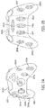
- FIGS. 2A and 2B show an example of a handheld interface device 200 (e.g., a handheld game controller) that has a plurality of electrodes 204a-204n disposed at respective portions of an outer surface 202 of the interface device 200.
- the handheld interface device 200 may include a plurality of user input components, such as thumbsticks, push buttons, and trigger buttons.
- the outer surface 202 may be divided into at least a front surface 202a and a back surface 202b.
- electrodes 204a-204e, 204n may be disposed at respective portions of the front surface 202a
- electrodes 204f-204m may be disposed at respective portions of the back surface 202b.
- the distance between adjacent electrodes may be substantially the same.
- one of the electrodes 204a-204n may be located at a portion at which a physical input component (e.g., thumbstick) is located. In some cases, there is no ESF electrode disposed at any physical input component.
- the electrodes 204a-204n may all be insulated electrodes, or may be a combination of, e.g., insulated signal electrodes and exposed ground electrodes.
- the electrodes 204a-204n may be placed at locations corresponding to different hand sizes.
- electrodes 204a, 204b, 204c, 204d, 204f, 2041, and 204j (or their respective portions of the outer surface 202) may correspond to locations that are more likely to be touched by a grip of a user having a bigger hand size.
- Electrodes 204e, 204g, 204m, 204i, 204k, and 204n may correspond to locations that are more likely to be touched by a grip of a user having a smaller hand size.
- a contact condition at each of the plurality of ESF electrodes may be determined.
- the contact condition may indicate whether a user is in contact with a respective portion of the outer surface that is formed by the electrode or that covers the electrode, or more specifically whether user contact is detected at the respective portion of the outer surface.
- FIG. 3A shows electrode 104i as an insulated electrode covered by a respective portion 102i of the outer surface 102 of the handheld interface device 100.
- the respective portion 102i may be the portion of the outer surface 102 which is disposed directly over the electrode 104i, and may have the same dimensions and boundaries as the electrode 104i.
- the contact condition for electrode 104i may indicate at least whether a user is in contact with the respective portion 102i of the outer surface 102.
- the contact condition may be represented through a binary value that indicates whether the user's finger or other body part is in contact with the respective portion 102i.
- the contact condition may indicate a degree of contact, if any, with the respective portion 102i.
- the degree of contact may be represented through a value indicating an area of the respective portion 102i that is in contact with the user, a level of pressure being exerted by the user's contact on the respective portion 102i, or some other value.
- the contact condition may be determined by inference (assumptions concerning the contact based on various criteria), by direct measurement with an electrode itself or with a separate sensor, or by some other technique.
- inferring the contact condition may involve inferring how the handheld interface device is being gripped (e.g., a grip posture). This inference may be based on various criteria or data, e.g., what application is running on a mobile phone or what game is being played with a game controller, or on an age of a user of the device.
- determining a contact condition may involve inferring whether, e.g., a mobile device is being held in a portrait orientation or a landscape orientation, and then identifying based on that inferred orientation which electrodes or their respective surface portions are likely to be in contact with a user.
- the presence of the user's skin on the respective portion 102i may affect (e.g., diminish) a signal (e.g., AC voltage) applied to electrode 104i by capacitively drawing current via the electrode 104i.
- a signal e.g., AC voltage
- the presence of a user's hand or other body part at the respective portion 102i can be detected.
- This driving signal used for measurement may be substantially lower in amplitude (e.g., 10 mV) than that used to generate a static ESF effect.
- a contact condition may be sensed through a contact sensor, such as a pressure sensor, a capacitive sensor, a resistive sensor, a piezoelectric sensor, any other contact sensor, or any combination thereof.
- FIGS. 3A-3C show contact sensors 302a-302g.
- a single contact sensor 302a may be used to sense a contact condition at the electrode 104i.
- the contact sensor 302a may be a pressure sensor.
- the pressure sensor maybe configured, for instance, to output an amount of pressure being transferred from the respective portion 102i of the outer surface to the pressure sensor, or it may be configured to output a binary value indicating whether a threshold amount of pressure on the respective portion 102i has been detected.
- contact sensor 302a may be a capacitive sensor configured to sense the presence of a user's skin at the respective portion 102i.
- a plurality of contact sensors (e.g., pressure sensors, capacitive sensors) 302b-302f may be located at electrode 104i.
- the plurality of contact sensors may collectively measure an area of the respective portion 102i that is in contact with a user, and/or a distribution of the contact.
- the plurality of contact sensors 302b-302f may be used to estimate a percentage of the respective portion 102i that is in contact with a user. If only, e.g., contact sensors 302b and 302d detects contact on the respective portion 102i, it may be determined that only the left 40% of the respective portion 102i is in contact with a user.
- the plurality of contact sensors 302b-302f may be arranged in various configurations, such as a staggered 2D array, as shown in FIG. 3B .
- the contact sensor 302g may have the same dimensions and boundaries as the electrode 104i, and may cover or be covered by the electrode.
- the contact sensor 302g may be a pressure sensor similar in functionality to contact sensor 302a in FIG. 3A .
- the contact sensor 302g may be a contact sensor configured to measure whether a user is in contact with the respective portion 102i covering the electrode 104i. In some instances, the output of the contact sensor 302g may depend on a percentage of the respective portion 102i that is in contact with the user.
- FIGS. 4A-4C show various sectional views, along the cross-sectional line A-A of FIG. 4 , of an electrode 104i and contact sensors 302d and 302f.
- FIG. 4A shows a sectional view in which electrode 104i is an exposed electrode that may be electrically coupled to a finger 402 through direct contact.
- contact sensors 302d and 302f may also be exposed, and thus may be considered to form a segment of the outer surface portion 102i.
- the depth of the contact sensors' placement may vary.
- FIG. 4B shows an embodiment in which the contact sensors 302d and 302f are located under the electrode 104i.
- electrode 104i is an insulated electrode that is covered by the respective portion 102i of the outer surface 102 of the handheld interface device 100, which has an insulating layer 404 separating the electrode 104i from the outer surface 102.
- the contact sensors 302d and 302f may also be insulated by the insulating layer 404 from direct contact with the finger 402, but may be located closer to the outer surface 102i.
- the placement of the contact sensors 302d, 302f may depend on the type of the contact sensor. For example, if the contact sensors 302d, 302f were pressure sensors, they may be exposed to the outer surface 102 (like in FIG. 4A ) or placed under the electrode 104i (like in FIG. 4B ). If the contact sensors 302d, 302fwere capacitive sensors, they may have the placement shown in FIGS. 4B or 4C .
- FIGS. 5A-5C are block diagrams showing examples of electrodes being signal electrodes or ground electrodes in handheld interface devices 100A-100C, respectively.
- FIGS. 5A and 5B both show a handheld interface device 100A and 100B, respectively, that has a first set of electrodes (104a, 104b, 104f, 104g, 104h, 104i, 104j) that are dedicated to being signal electrodes, and a second set of electrodes (electrodes 104c, 104d, 104e) that are dedicated to being ground electrodes.
- the first set of electrodes may be dedicated to being signal electrodes in the sense that they can be used as signal electrodes (e.g., can be switchably connected to a signal generator), but cannot be used as ground electrodes.
- the second set of electrodes may be dedicated to being ground electrodes in the sense that they can be used as ground electrodes (e.g., permanently or switchably connected to ground), but cannot be used as signal electrodes.
- the driving signal for an ESF effect may be generated by a signal generating circuit 504 that is part of a control unit 502 of the handheld interface device 100A, 100B.
- the signal generating circuit 504 may comprise a low-voltage digital to analog converter (DAC) and an amplifier which is configured to amplify the output of the DAC to a high voltage (e.g., 1.5 kV).
- DAC digital to analog converter
- the output of the signal generating circuit 504 may be selectively electrically connected to one or more electrodes of the first set of electrodes (104a, 104b, 104f, 104g, 104h, 104i, 104j) by a switching device 506 (e.g., a multiplexor).
- the switching device 506 may be controlled by control unit 502.
- each electrode in the first set of electrodes (104a, 104b, 104f, 104g, 104h, 104i, 104j) in FIGS. 5A and 5B may be switchable to being a signal electrode.
- Electrodes in the first set which are not electrically connected to the output of the signal generating circuit 504 by the switching device 506 may be in an electrically floating state (i.e., have a floating electrical potential).
- each electrode in the second set of electrodes may be a dedicated ground electrode permanently electrically connected to a ground potential.
- each electrode in the second set of electrodes (104c, 104d, 104e) may be dedicated to being a ground electrode, and is switchable between being electrically connected to the ground potential by switching device 508 and being in an electrically floating state.
- the switching device 508 may be controlled by the control unit 502.
- FIG. 5C provides a block diagram of a handheld interface device 100C that includes a plurality of electrodes (104a-104j) that may each be an electrode (e.g., insulated electrode) switchable between being a signal electrode and being a ground electrode.
- An electrode in the plurality of electrodes may be switched to being a signal electrode by being electrically connected to an output of the signal generating circuit 504.
- a switching device 510 e.g., a multiplexor
- a switching device 512 may be configured to electrically connect one or more electrodes of the plurality of electrodes 104a-104j to a ground potential. Both the switching device 510 and the switching device 512 may be controlled by the control unit 502. In an embodiment, the switching device 510 and the switching device 512 may both be part of a single switching device. In one example, electrodes which are not electrically connected to the output of the signal generating circuit 504 nor to the ground potential may be in an electrically floating state. In an embodiment, an electrode in FIG.
- 5A , 5B , or 5C that is a signal electrode or switchable to being a signal electrode may be considered disabled from being a signal electrode if it is in the electrically floating state, or is grounded.
- an electrode in FIG. 5B or 5C that is switchable to being a ground electrode may be considered disabled from being a ground electrode if it is in the electrically floating state.
- FIG. 6 provides a flow diagram which illustrates example steps of a method 600 by which a handheld interface device provides an electrostatic friction (ESF) effect (e.g., static ESF) to a user, and involves the selection of electrodes based on contact conditions.
- the handheld interface device e.g., device 100
- the handheld interface device may comprise a plurality of electrodes (e.g., more than two electrodes), with each electrode (e.g., electrode 104i) of the plurality of electrodes being separately disposed at a respective portion (e.g., portion 102i) of an outer surface of the interface device.
- Each electrode of the plurality of electrodes may be an exposed electrode or an insulated electrode that is covered by or forms the electrode's respective portion of the outer surface.
- the electrode may be configured to be electrically coupled, directly or capacitively, with the user upon the user making contact with the electrode's respective portion of the outer surface.
- method 600 begins at step 602, in which a control unit of the handheld interface device determines a contact condition at each electrode (e.g., electrode 104i) of the plurality of electrodes (e.g., electrodes 104a-104j).
- the contact condition may indicate whether user contact has been detected at the respective portion (e.g., 102i) of the outer surface that is formed by the electrode or that covers the electrode.
- the determined contact condition for each electrode of the plurality of electrodes may indicate a quality level of any detected user contact at the respective portion of the outer surface.
- the contact condition for an electrode may indicate at least one of: i) an area of any user contact at the respective portion (e.g., 102i) of the outer surface formed by or covering the electrode (the strength of the sensation may increase with the area of contact), such as via an array of contact sensors; ii) an amount of pressure exerted by any user contact on the respective portion (e.g., 102i) of the outer surface (the sensation may be weaker when too much or too little pressure is applied), such as via a pressure sensor or via calculation based on bending of the outer surface 102 or (if the method 600 were applied to a wearable device such as a wrist band) tightness of the band; and iii) a pressure distribution of any user contact across the respective portion of the outer surface.
- the contact condition for an electrode whose respective portion of the outer surface in contact with a user indicates at least one of: i) a level of humidity of a portion of a user in contact with the respective portion of the outer surface formed by or covering the electrode (the sensation may be strongest when the humidity of the skin in contact with the portion is in a certain range), such as with a corneometer or other sensor, and, ii) which location on a user (e.g., hand, wrist, or arm) is in contact with the respective portion of the outer surface, such as via sensor data.
- a dry ground electrode may function adequately against a palm or finger, but may cause a burning sensation on the wrist.
- control unit may be configured to determine the contact conditions for the plurality of electrodes based on at least one of: i) measurements from a plurality of contact sensors configured to sense user contact at respective ones of the plurality of electrodes; ii) measurements from the plurality of electrodes; iii) an identity of an application being executed on the handheld interface device or receiving input from the handheld interface device; and iv) stored or detected information indicative of a hand size of a user using the handheld interface device.
- the control unit is configured to determine a grip position indicating how the handheld interface device is currently being gripped, and to determine the contact conditions for the plurality of electrodes based on the determined grip position.
- the handheld interface device may comprise a display (e.g., touch screen 108), and the control unit may be configured to determine the grip position based on whether an image is oriented in portrait mode or landscape mode on the display.
- the contact sensors may be used to detect user contact with the interface device.
- the sensors could be placed on or under the electrodes to directly detect contact.
- the contact sensors can detect contact, pressure, pressure distribution, and whether the object making contact is skin.
- sensors e.g., contact sensors or sensors other than contact sensors
- Contact sensors could also be placed on other parts of the device and used to infer user contact with the electrodes.
- Contact sensors could include capacitive sensors, pressure sensors, or any other contact sensor.
- the use of the identity of the application or the stored or detected information may be part of inferring a contact condition at an electrode. For instance, this inference may involve estimating whether the respective location of a particular electrode is likely to be in user contact, or estimating a degree of user contact, based on information indicating how the interface device is being held by a user, information about the user holding the interface device, and/or other information.
- the identity of the application running on a mobile phone may indicate a grip posture (e.g., whether the phone is being held in a portrait orientation or a landscape orientation).
- the grip posture of a mobile phone may vary based on whether the application involves a keyboard typing task (which more typically involves a landscape orientation), involves a game with virtual buttons, involves a video such as a Netflix stream, involves a game for a child versus an adult (which may be used to infer hand size), etc.
- the grip posture inferred from the identity of the application may map to a particular subset of electrodes whose respective surface portions were previously determined as likely to contact a user in that grip posture.
- the detected or stored information may be used to infer a hand size, preferred grip posture, etc.
- the information may include demographic information about a current user of the device. For instance, a game console may have the profile of a player, such as gender and/or age. This information may be used to estimate the hand size and likely grip of a game controller.
- the information may be detected by asking the user to explicitly pick a hand size (e.g., between small, medium, large), or by measuring the user's hand, such as by comparing an image of the user's hand to a template (e.g., different hand sizes shown on a tablet computer).
- control unit may select a subset of the plurality of electrodes based on the determined contact condition at each electrode of the plurality of electrodes. For instance, a control unit (e.g., control unit 502) may select an electrode with the best contact condition, which may be, e.g., the largest contact area, the most uniform pressure distribution, the most optimal humidity value, the electrode which is in contact with the most optimal body part, and/or the electrode that is in contact with the user and has the minimum pressure.
- a control unit e.g., control unit 502
- the best contact condition which may be, e.g., the largest contact area, the most uniform pressure distribution, the most optimal humidity value, the electrode which is in contact with the most optimal body part, and/or the electrode that is in contact with the user and has the minimum pressure.
- the plurality of electrodes may be divided into a first set of exposed electrodes dedicated to being ground electrodes, and a second set of insulated electrodes dedicated to being signal electrodes.
- step 604 may be specifically selecting a subset of electrodes (e.g., only one electrode) from the second set of insulated electrodes to be signal electrodes.
- a driving signal may then be multiplexed to the selected electrode, while the remaining electrodes in the first set of electrodes may be disconnected from the driving signal.
- all electrodes in the first set of exposed electrodes may be used as ground electrodes, or a subset of the electrodes from the first set may be selected to be ground electrodes.
- the plurality of electrodes of the handheld interface device may all be insulated electrodes that are each switchable between being a signal electrode and a ground electrode.
- the control unit in step 604 may be selecting a subset of electrodes in which some electrode(s) in the subset will be used as signal electrode(s), while other electrode(s) of the subset will be used as ground electrode(s). For instance, the control unit in step 604 may select from the plurality of insulated electrodes at least two electrodes that have the best contact conditions, and then connect one of the at least two insulated electrodes to the driving signal, and connect another of the at least two insulated electrodes to ground.
- control unit may select a subset number of electrodes (e.g., four electrodes) having the best contact conditions, and select from that subset a predetermined number (e.g., one) of the smallest electrodes to be ground electrodes, and then assign the remaining electrodes in the subset to be signal electrodes.
- the number of electrodes selected as a signal electrode may be only one, or more than one.
- electrodes which are not in the selected subset of electrodes may be left in an electrically floating state. In another embodiment, electrodes which are not in the selected subset of electrodes may be grounded.
- the control unit may apply a drive signal for generating electrostatic friction to only one or more electrodes in the selected subset of the plurality of electrodes. In other words, the control unit refrains from applying the drive signal to electrodes that are not in the selected subset, as this may save power.
- the control unit may apply the drive signal to all electrodes in the selected subset of electrodes.
- the control unit in step 606 may apply the drive signal to only the signal electrodes in the selected subset of electrodes, and not to the ground electrodes in the selected subset of electrodes.
- FIG. 7 provides a flow diagram which illustrates steps of a method 700 by which a handheld interface device determines whether to provide an electrostatic friction (ESF) effect to a user in accordance with another embodiment hereof. While method 600 in FIG. 6 involves selecting an electrode to which an ESF drive signal is applied, the method 700 in FIG. 7 may disable ESF effects in the device if contact conditions are poor for all electrodes that are ground electrodes or switchable to being ground electrodes.
- ESF electrostatic friction
- the handheld interface device (e.g., device 100) in method 700 may comprise a plurality of electrodes (e.g., more than two electrodes), with each electrode (e.g., electrode 104i) of the plurality of electrodes being separately disposed at a respective portion (e.g., portion 102i) of an outer surface of the interface device.
- the plurality of electrodes may comprise a first set of one or more electrodes that are each a ground electrode or an electrode switchable to being a ground electrode, and a second set of one or more electrodes that are each a signal electrode or an electrode switchable to being a signal electrode.
- Each of the electrodes may be covered by the electrode's respective portion of the outer surface or may form the electrode's respective portion of the outer surface.
- method 700 begins at step 702, in which a control unit of the handheld interface device determines a contact condition at each electrode of the plurality of electrodes.
- the contact condition may be determined in a manner similar to step 602.
- step 704 the control unit determines, based on the contact condition at each of the plurality of electrodes, that no user contact has been detected at the first set of one or more electrodes, or that user contact has been detected at only one electrode of the plurality of electrodes.
- ESF effects in a handheld interface device may be disabled if no user contact has been detected at the first set of one or more electrodes. This may apply to, e.g., a handheld interface device in which the first set of electrodes are dedicated to being signal electrodes, and all other electrodes are dedicated to being ground electrodes. In such a situation, the user would not be in contact with any potential signal electrode. Thus, the handheld interface device may be unable to apply a driving signal to the user.
- the device may then disable ESF effects by, e.g., refraining from generating a signal with the signal generating circuit 504, powering down the signal generating circuit 504, electrically disconnecting all electrodes from the signal generating circuit 504, leaving all electrodes in an electrically floating state, and/or electrically connecting all electrodes to ground.
- ESF effects may be disabled if user contact has been detected at only one electrode of the plurality of electrodes is in contact with the user. This may apply to, e.g., a handheld interface device that has only insulated electrodes which are each switchable between being a signal electrode and being a ground electrode. In some cases, the ESF effect may be too faint if a user is in contact with only one or more signal electrodes, and is not in contact with a ground electrode. If only one electrode of the plurality of electrodes is in contact with a user, this electrode may be unable to be both a signal electrode and a ground electrode simultaneously. Thus, any ESF effect in this situation may be too faint.
- the handheld interface device may therefore disable ESF effects by, e.g., powering down the signal generating circuit and/or electrically connecting all electrodes to the ground potential.
- the control unit in response to determining that no user contact has been detected at the first set of one or more electrodes or that user contact has been detected at only one electrode of the plurality of electrodes, the control unit as discussed above may disable ESF effects on the handheld interface device by disabling all electrodes in the second set of one or more electrodes.
- ESF effects may be disabled by, e.g., disabling the signal electrode. The disabling of the ESF effects may be performed even when at least one of the disabled one or more signal electrodes is in contact with the user.
- An electrode in the second set of one or more electrodes may be disabled by, e.g., leaving the electrode in an electrically floating state, or electrically connecting the electrode to a ground state.
- FIGS. 8A-8C illustrate example grips of a handheld interface device, such as a mobile phone. These examples show how the locations at which a user grips the mobile phone changes based on an orientation of the mobile phone and/or how the mobile phone is being used.
- the mobile phone is in a landscape orientation and is being used to, e.g., present a user-interactive game.
- the mobile phone may be more likely to be gripped through user contact at a center of its back surface and on one of its shorter side surfaces.
- the mobile phone may also be likely to receive user contact on its front surface (on the touch screen) as a way of receiving user input.
- FIG. 8A the mobile phone is in a landscape orientation and is being used to, e.g., present a user-interactive game.
- the mobile phone may be more likely to be gripped through user contact at a center of its back surface and on one of its shorter side surfaces.
- the mobile phone may also be likely to receive user contact on its front surface (on the touch screen) as a
- the mobile phone is in a portrait orientation and is being used, e.g., to receive user input for typing a text message.
- the mobile phone may be more likely to be gripped through user contact on its longer side surfaces.
- the mobile phone may also receive user contact on its front surface (on the touch screen) as a way of receiving user input.
- the mobile phone is also in a landscape orientation, like in FIG. 8A , but may be used to present a video that is not user interactive. In this context, the mobile phone may be more likely to be gripped on both of its shorter side surfaces.
- electrodes on the left and right sides of the device may be selectively activated as ground and signal electrodes.
- two electrodes on the back may be selectively activated for the signal and ground electrodes.
- electrodes on the edge and back may be selectively activated for the signal and ground electrodes.
- FIGS. 9A-9C illustrate example grips of a handheld interface device, such as a game controller.
- the figures show that various fingers on a user's hand or various portions on a user's palm may change where they contact the game controller, or whether they contact the game controller based on user preference, a game being played or a scenario in the game being played, or any other factor.
- Embodiments herein may be used for a mobile phone, gaming, automotive, augmented reality (AR), virtual reality (VR), or wearables application.
- the handheld interface device may be a controller for a VR or AR application.
- Embodiments herein may be used for dynamic ESF effects or static ESF effects.
- the drive signal applied to the selected subset of the plurality of electrodes may have an amplitude of at least 1 kV.
Landscapes
- Engineering & Computer Science (AREA)
- Theoretical Computer Science (AREA)
- General Engineering & Computer Science (AREA)
- Physics & Mathematics (AREA)
- General Physics & Mathematics (AREA)
- Human Computer Interaction (AREA)
- Computer Hardware Design (AREA)
- Software Systems (AREA)
- Multimedia (AREA)
- Computer Graphics (AREA)
- Remote Sensing (AREA)
- Radar, Positioning & Navigation (AREA)
- User Interface Of Digital Computer (AREA)
- Telephone Set Structure (AREA)
Applications Claiming Priority (1)
| Application Number | Priority Date | Filing Date | Title |
|---|---|---|---|
| US15/355,353 US10534435B2 (en) | 2016-11-18 | 2016-11-18 | Handheld interface device having a plurality of electrostatic friction (ESF) electrodes |
Publications (1)
| Publication Number | Publication Date |
|---|---|
| EP3324273A1 true EP3324273A1 (fr) | 2018-05-23 |
Family
ID=60387881
Family Applications (1)
| Application Number | Title | Priority Date | Filing Date |
|---|---|---|---|
| EP17202201.4A Withdrawn EP3324273A1 (fr) | 2016-11-18 | 2017-11-17 | Dispositif d'interface portable comportant une pluralité d'électrodes à friction électrostatique |
Country Status (5)
| Country | Link |
|---|---|
| US (1) | US10534435B2 (fr) |
| EP (1) | EP3324273A1 (fr) |
| JP (1) | JP2018081696A (fr) |
| KR (1) | KR20180056384A (fr) |
| CN (1) | CN108073282A (fr) |
Families Citing this family (2)
| Publication number | Priority date | Publication date | Assignee | Title |
|---|---|---|---|---|
| CN109491501B (zh) * | 2018-11-07 | 2022-05-20 | Oppo广东移动通信有限公司 | 电子设备使用控制方法、装置、电子设备和存储介质 |
| TWI803134B (zh) * | 2021-09-24 | 2023-05-21 | 宏達國際電子股份有限公司 | 虛擬影像顯示裝置及其輸入介面的設定方法 |
Citations (5)
| Publication number | Priority date | Publication date | Assignee | Title |
|---|---|---|---|---|
| EP2784630A1 (fr) * | 2013-03-13 | 2014-10-01 | Immersion Corporation | Procédé et dispositifs permettant d'afficher des interfaces graphiques d'utilisateur sur la base de contact de l'utilisateur |
| EP2851763A1 (fr) * | 2013-09-18 | 2015-03-25 | Immersion Corporation | Dispositif haptique multicanal à orientation réglable |
| US20150185849A1 (en) * | 2013-12-31 | 2015-07-02 | Immersion Corporation | Systems and methods for providing haptic notifications |
| EP2963523A1 (fr) * | 2014-07-02 | 2016-01-06 | Immersion Corporation | Systèmes et procédés pour produire des effets haptiques électrostatiques à sorties multiples |
| WO2016048207A1 (fr) * | 2014-09-25 | 2016-03-31 | Telefonaktiebolaget L M Ericsson (Publ) | Dispositif de communication mobile présentant un frottement adaptatif du boîtier |
Family Cites Families (19)
| Publication number | Priority date | Publication date | Assignee | Title |
|---|---|---|---|---|
| US8054289B2 (en) * | 2006-12-01 | 2011-11-08 | Mimic Technologies, Inc. | Methods, apparatus, and article for force feedback based on tension control and tracking through cables |
| EP2790088B1 (fr) | 2007-09-18 | 2019-05-01 | Senseg Oy | Procédé et appareil de stimulation sensorielle |
| JP5302610B2 (ja) * | 2008-10-01 | 2013-10-02 | キヤノン株式会社 | 情報処理装置、情報処理方法 |
| EP3031689B1 (fr) * | 2008-10-03 | 2017-07-05 | Senseg Oy | Techniques permettant de présenter des informations relatives à un véhicule |
| US9417694B2 (en) | 2009-10-30 | 2016-08-16 | Immersion Corporation | System and method for haptic display of data transfers |
| US8766933B2 (en) * | 2009-11-12 | 2014-07-01 | Senseg Ltd. | Tactile stimulation apparatus having a composite section comprising a semiconducting material |
| US9501145B2 (en) * | 2010-05-21 | 2016-11-22 | Disney Enterprises, Inc. | Electrovibration for touch surfaces |
| WO2012154972A2 (fr) * | 2011-05-10 | 2012-11-15 | Northwestern University | Dispositif à interface tactile ayant une surface multi-tactile électrostatique et procédé pour la commande du dispositif |
| JP5875069B2 (ja) * | 2012-03-22 | 2016-03-02 | 任天堂株式会社 | ゲームシステム、ゲーム処理方法、ゲーム装置、およびゲームプログラム |
| JP2013242655A (ja) * | 2012-05-18 | 2013-12-05 | Panasonic Corp | 情報端末の表示制御装置および表示制御方法 |
| WO2014002405A1 (fr) | 2012-06-29 | 2014-01-03 | パナソニック株式会社 | Dispositif à panneau tactile présentant une fonction de retour tactile |
| US9639158B2 (en) * | 2013-11-26 | 2017-05-02 | Immersion Corporation | Systems and methods for generating friction and vibrotactile effects |
| US20150205352A1 (en) * | 2013-12-29 | 2015-07-23 | Immersion Corporation | Distributed control architecture for haptic devices |
| JP2015231098A (ja) * | 2014-06-04 | 2015-12-21 | ソニー株式会社 | 振動装置、および振動方法 |
| US10031582B2 (en) * | 2014-06-05 | 2018-07-24 | Immersion Corporation | Systems and methods for induced electrostatic haptic effects |
| US9606624B2 (en) * | 2014-07-02 | 2017-03-28 | Immersion Corporation | Systems and methods for surface elements that provide electrostatic haptic effects |
| KR102384103B1 (ko) * | 2014-08-26 | 2022-04-07 | 엘지디스플레이 주식회사 | 터치 패널의 구동 장치 |
| JP2016162364A (ja) * | 2015-03-04 | 2016-09-05 | ソニー株式会社 | 入力装置および情報処理装置 |
| KR101739791B1 (ko) * | 2015-05-11 | 2017-05-26 | 주식회사 하이딥 | 압력 센싱 장치, 압력 검출기 및 이들을 포함하는 장치 |
-
2016
- 2016-11-18 US US15/355,353 patent/US10534435B2/en not_active Expired - Fee Related
-
2017
- 2017-11-15 KR KR1020170152001A patent/KR20180056384A/ko unknown
- 2017-11-16 CN CN201711137972.5A patent/CN108073282A/zh active Pending
- 2017-11-17 EP EP17202201.4A patent/EP3324273A1/fr not_active Withdrawn
- 2017-11-17 JP JP2017221411A patent/JP2018081696A/ja not_active Ceased
Patent Citations (5)
| Publication number | Priority date | Publication date | Assignee | Title |
|---|---|---|---|---|
| EP2784630A1 (fr) * | 2013-03-13 | 2014-10-01 | Immersion Corporation | Procédé et dispositifs permettant d'afficher des interfaces graphiques d'utilisateur sur la base de contact de l'utilisateur |
| EP2851763A1 (fr) * | 2013-09-18 | 2015-03-25 | Immersion Corporation | Dispositif haptique multicanal à orientation réglable |
| US20150185849A1 (en) * | 2013-12-31 | 2015-07-02 | Immersion Corporation | Systems and methods for providing haptic notifications |
| EP2963523A1 (fr) * | 2014-07-02 | 2016-01-06 | Immersion Corporation | Systèmes et procédés pour produire des effets haptiques électrostatiques à sorties multiples |
| WO2016048207A1 (fr) * | 2014-09-25 | 2016-03-31 | Telefonaktiebolaget L M Ericsson (Publ) | Dispositif de communication mobile présentant un frottement adaptatif du boîtier |
Also Published As
| Publication number | Publication date |
|---|---|
| US20180143685A1 (en) | 2018-05-24 |
| US10534435B2 (en) | 2020-01-14 |
| KR20180056384A (ko) | 2018-05-28 |
| JP2018081696A (ja) | 2018-05-24 |
| CN108073282A (zh) | 2018-05-25 |
Similar Documents
| Publication | Publication Date | Title |
|---|---|---|
| KR101021440B1 (ko) | 터치입력장치, 이를 이용한 휴대기기 및 그 제어방법 | |
| KR101390164B1 (ko) | 광학적으로 투명한 시트를 포함하는 장치 및 관련된 방법 | |
| US9791930B1 (en) | Determination of input from force sensing input device under an unbroken exterior portion of a device | |
| US9110545B2 (en) | Apparatus and associated methods | |
| US9323326B2 (en) | Haptic output device and method of generating a haptic effect in a haptic output device | |
| US9349551B2 (en) | Keyboard with elastic member disposed on touch panel | |
| EP3309659A1 (fr) | Systèmes et procédés pour fournir des effets haptiques électrostatiques par l'intermédiaire d'un dispositif portatif ou portable | |
| TW201533639A (zh) | 電容式手指導航模組及其製作方法 | |
| US20200012348A1 (en) | Haptically enabled overlay for a pressure sensitive surface | |
| EP3324273A1 (fr) | Dispositif d'interface portable comportant une pluralité d'électrodes à friction électrostatique | |
| KR20190072989A (ko) | 촉각 센서, 그 제조 방법 및 그 동작 방법 | |
| CN110307835B (zh) | 导航提醒方法、装置、存储介质和电子设备 | |
| CN116194874A (zh) | 用于电子设备的机械灵敏高功效触笔 | |
| WO2021202612A2 (fr) | Protection contre les décharges électrostatiques d'un stylet à faible consommation d'énergie pour un dispositif électronique | |
| JP6913554B2 (ja) | タッチパネル、タッチ式入力装置 | |
| CN106997256A (zh) | 金属壳中的嵌入式电容传感器 | |
| JP4357980B2 (ja) | 座標入力装置 | |
| KR20170056915A (ko) | 정전용량의 변화를 이용한 필압 인식 터치펜 장치 | |
| JP2019528504A (ja) | 近接感知を備えた入力デバイスにおける指追跡 |
Legal Events
| Date | Code | Title | Description |
|---|---|---|---|
| PUAI | Public reference made under article 153(3) epc to a published international application that has entered the european phase |
Free format text: ORIGINAL CODE: 0009012 |
|
| STAA | Information on the status of an ep patent application or granted ep patent |
Free format text: STATUS: THE APPLICATION HAS BEEN PUBLISHED |
|
| AK | Designated contracting states |
Kind code of ref document: A1 Designated state(s): AL AT BE BG CH CY CZ DE DK EE ES FI FR GB GR HR HU IE IS IT LI LT LU LV MC MK MT NL NO PL PT RO RS SE SI SK SM TR |
|
| AX | Request for extension of the european patent |
Extension state: BA ME |
|
| STAA | Information on the status of an ep patent application or granted ep patent |
Free format text: STATUS: REQUEST FOR EXAMINATION WAS MADE |
|
| 17P | Request for examination filed |
Effective date: 20181122 |
|
| RBV | Designated contracting states (corrected) |
Designated state(s): AL AT BE BG CH CY CZ DE DK EE ES FI FR GB GR HR HU IE IS IT LI LT LU LV MC MK MT NL NO PL PT RO RS SE SI SK SM TR |
|
| STAA | Information on the status of an ep patent application or granted ep patent |
Free format text: STATUS: THE APPLICATION HAS BEEN WITHDRAWN |
|
| 18W | Application withdrawn |
Effective date: 20200312 |