EP3324266A1 - Apparatus for controlling and operating an autonomous vehicle - Google Patents
Apparatus for controlling and operating an autonomous vehicle Download PDFInfo
- Publication number
- EP3324266A1 EP3324266A1 EP17191438.5A EP17191438A EP3324266A1 EP 3324266 A1 EP3324266 A1 EP 3324266A1 EP 17191438 A EP17191438 A EP 17191438A EP 3324266 A1 EP3324266 A1 EP 3324266A1
- Authority
- EP
- European Patent Office
- Prior art keywords
- compartment
- subsystem
- chassis
- server
- ethernet
- Prior art date
- Legal status (The legal status is an assumption and is not a legal conclusion. Google has not performed a legal analysis and makes no representation as to the accuracy of the status listed.)
- Granted
Links
Images




Classifications
-
- H—ELECTRICITY
- H05—ELECTRIC TECHNIQUES NOT OTHERWISE PROVIDED FOR
- H05K—PRINTED CIRCUITS; CASINGS OR CONSTRUCTIONAL DETAILS OF ELECTRIC APPARATUS; MANUFACTURE OF ASSEMBLAGES OF ELECTRICAL COMPONENTS
- H05K7/00—Constructional details common to different types of electric apparatus
- H05K7/14—Mounting supporting structure in casing or on frame or rack
- H05K7/1485—Servers; Data center rooms, e.g. 19-inch computer racks
-
- G—PHYSICS
- G06—COMPUTING OR CALCULATING; COUNTING
- G06F—ELECTRIC DIGITAL DATA PROCESSING
- G06F13/00—Interconnection of, or transfer of information or other signals between, memories, input/output devices or central processing units
- G06F13/38—Information transfer, e.g. on bus
- G06F13/40—Bus structure
- G06F13/4004—Coupling between buses
- G06F13/4022—Coupling between buses using switching circuits, e.g. switching matrix, connection or expansion network
-
- G—PHYSICS
- G06—COMPUTING OR CALCULATING; COUNTING
- G06F—ELECTRIC DIGITAL DATA PROCESSING
- G06F1/00—Details not covered by groups G06F3/00 - G06F13/00 and G06F21/00
- G06F1/16—Constructional details or arrangements
- G06F1/18—Packaging or power distribution
- G06F1/181—Enclosures
-
- G—PHYSICS
- G06—COMPUTING OR CALCULATING; COUNTING
- G06F—ELECTRIC DIGITAL DATA PROCESSING
- G06F1/00—Details not covered by groups G06F3/00 - G06F13/00 and G06F21/00
- G06F1/16—Constructional details or arrangements
- G06F1/20—Cooling means
-
- G—PHYSICS
- G06—COMPUTING OR CALCULATING; COUNTING
- G06F—ELECTRIC DIGITAL DATA PROCESSING
- G06F1/00—Details not covered by groups G06F3/00 - G06F13/00 and G06F21/00
- G06F1/26—Power supply means, e.g. regulation thereof
- G06F1/266—Arrangements to supply power to external peripherals either directly from the computer or under computer control, e.g. supply of power through the communication port, computer controlled power-strips
-
- G—PHYSICS
- G06—COMPUTING OR CALCULATING; COUNTING
- G06F—ELECTRIC DIGITAL DATA PROCESSING
- G06F13/00—Interconnection of, or transfer of information or other signals between, memories, input/output devices or central processing units
- G06F13/38—Information transfer, e.g. on bus
- G06F13/42—Bus transfer protocol, e.g. handshake; Synchronisation
- G06F13/4204—Bus transfer protocol, e.g. handshake; Synchronisation on a parallel bus
- G06F13/4221—Bus transfer protocol, e.g. handshake; Synchronisation on a parallel bus being an input/output bus, e.g. ISA bus, EISA bus, PCI bus, SCSI bus
-
- G—PHYSICS
- G06—COMPUTING OR CALCULATING; COUNTING
- G06F—ELECTRIC DIGITAL DATA PROCESSING
- G06F13/00—Interconnection of, or transfer of information or other signals between, memories, input/output devices or central processing units
- G06F13/38—Information transfer, e.g. on bus
- G06F13/42—Bus transfer protocol, e.g. handshake; Synchronisation
- G06F13/4282—Bus transfer protocol, e.g. handshake; Synchronisation on a serial bus, e.g. I2C bus, SPI bus
-
- H—ELECTRICITY
- H05—ELECTRIC TECHNIQUES NOT OTHERWISE PROVIDED FOR
- H05K—PRINTED CIRCUITS; CASINGS OR CONSTRUCTIONAL DETAILS OF ELECTRIC APPARATUS; MANUFACTURE OF ASSEMBLAGES OF ELECTRICAL COMPONENTS
- H05K7/00—Constructional details common to different types of electric apparatus
- H05K7/02—Arrangements of circuit components or wiring on supporting structure
- H05K7/10—Plug-in assemblages of components, e.g. IC sockets
-
- G—PHYSICS
- G06—COMPUTING OR CALCULATING; COUNTING
- G06F—ELECTRIC DIGITAL DATA PROCESSING
- G06F2213/00—Indexing scheme relating to interconnection of, or transfer of information or other signals between, memories, input/output devices or central processing units
- G06F2213/0024—Peripheral component interconnect [PCI]
-
- G—PHYSICS
- G06—COMPUTING OR CALCULATING; COUNTING
- G06F—ELECTRIC DIGITAL DATA PROCESSING
- G06F2213/00—Indexing scheme relating to interconnection of, or transfer of information or other signals between, memories, input/output devices or central processing units
- G06F2213/0026—PCI express
Definitions
- Embodiments of the present invention relate generally to operating autonomous vehicles. More particularly, embodiments of the invention relate to an apparatus for controlling and operating an autonomous vehicle.
- Vehicles operating in an autonomous mode can relieve occupants, especially the driver, from some or all driving-related responsibilities.
- the vehicle can navigate to various locations using onboard sensors, allowing the vehicle to travel with minimal human interaction or in some cases without any passengers.
- Embodiments of the disclosure provide an apparatus for controlling and operating an autonomous vehicle.
- the apparatus for controlling and operating an autonomous vehicle comprises: a chassis housing a plurality of compartments, including a control server compartment, a compute server compartment, and an input and output (IO) subsystem compartment; an IO subsystem inserted into the IO subsystem compartment, the IO subsystem having a plurality of IO modules, wherein at least some of the IO modules are to be coupled to one or more sensors; a compute server inserted into the compute server compartment, wherein the compute server receives the sensor data from the IO subsystem via a plurality of Peripheral Component Interconnect Express (PCIe) links and generates planning and control data based on the sensor data for controlling the autonomous vehicle; and a control server inserted into the control server compartment coupled to the compute server via an Ethernet connection, wherein the control server controls and operates the autonomous vehicle by sending a plurality of control commands to hardware of the autonomous vehicle based on the planning and control data received from the compute server.
- PCIe Peripheral Component Interconnect Express
- an autonomous driving hardware platform provides an integrated and compact high performance computing environment that fits in a vehicle trunk.
- a hardware platform includes a chassis to house a number of compartments, including a control server compartment, a compute server compartment, and an input and output (IO) subsystem compartment.
- the platform further includes an IO subsystem inserted into the IO subsystem compartment, a compute server inserted into the compute server compartment, and a control server inserted into the control server compartment.
- the IO subsystem includes a number of IO modules. At least some of the IO modules can be coupled to one or more sensors.
- the sensors can sense a surrounding environment of an autonomous vehicle and generate sensor data perceiving the surrounding environment of the autonomous vehicle.
- the compute server is the single computer that receives the sensor data from the IO subsystem via one or more Peripheral Component Interconnect Express (PCIe) links and makes planning and control decisions based on the sensor data for controlling the autonomous vehicle in contrast of using multiple computers connected over Ethernet.
- PCIe Peripheral Component Interconnect Express
- the control server then controls and drives the autonomous vehicle by sending proper control commands to the autonomous vehicle based on the planning and control decisions received from the compute server.
- FIGS 1A and 1B show perspective views of a hardware platform for controlling and operating an autonomous vehicle according to one embodiment of the invention.
- platform 100 includes a chassis having a frontend or front side 101, backend or back side 102, top end or top side 103, and a bottom end or bottom side (not shown).
- Frontend 101 is covered by front panel 105 while top end 103 is covered by top panel 107.
- both sides are covered by side panels 104A and 104B (as shown in Figure 1B ).
- Each of the side panels 104A and 104B includes a handle that can be utilized by a user to carry platform 100 as a portable platform.
- the chassis includes various compartments to store or contain various subsystems, such as, for example, IO subsystem 111 and storage module 112 (also referred to as a storage unit) in this front perspective view as shown in Figure 1A .
- Top panel 107 can be removed to allow IO subsystem 111 and storage module 112 to be inserted into or removed from the IO subsystem compartment and storage compartment respectively as shown in Figure 5 .
- Top panel further includes an opening or window to expose a frontend or an interface of IO subsystem 111 and storage module 112 upwardly, for example, to allow user accessing the components (e.g., inserting or removing an individual IO module or storage card).
- Front panel 105 includes one or more openings (or windows or cutouts) to expose certain connectors or interfaces of IO subsystem 111. Further, top panel 107 includes a screen portion 108 to for air circulation (referred to as an air intake screen) for the purpose of cooling the components contained within the chassis.
- an air intake screen to for air circulation
- backend 102 is covered by back panel 106 having various openings to allow certain components to be inserted into or removed from their respective compartments.
- platform 100 includes compute server 113 inserted into a compute server compartment, control server 114 inserted into a control server compartment, and Ethernet switch module 115 inserted into an Ethernet switch compartment.
- the compute server compartment and the control server compartment are positioned in a substantially horizontal orientation, as shown in Figure 5 .
- compute server 113 is inserted into or removed from the compute server compartment horizontally from backend 102.
- control server 114 is inserted into or removed from the control server compartment horizontally from backend 102.
- the control server compartment is positioned above the compute server compartment.
- the frontends of compute server 113 and control server 114 are exposed via the corresponding openings of back panel 106.
- Ethernet switch module 115 is inserted into or removed from the Ethernet switch compartment vertically from top end 103.
- Back panel 106 includes an opening to expose Ethernet connectors (e.g., Ethernet sockets) to allow other components such as compute server 113 and control server 114 to communicate with each other over the Ethernet.
- the Ethernet switch compartment is positioned above the control server compartment.
- Back panel 106 further includes one or more openings to expose an interface of another side of IO subsystem 111 to allow the IO subsystem 111 to be coupled to other components such as compute server 113 using appropriate cables.
- Back panel 106 further includes one or more screens 109 for air circulation (referred to as an air exhaustion screen) for the purpose of cooling the components contained in the chassis.
- the cool air is drawn into the chassis from the air intake screen 108 from top end 103, travels downwardly through the air space between the components contained in the chassis (e.g., Ethernet switch module 115, storage module 112, control server 114, and compute server 113) to exchange heat generated from the components, and exits the chassis through the screens 125-126 disposed on the frontends of control server 114 and compute server 113.
- a portion of the cool air travels through a power supply unit (not shown) to exchange heat generated therein and exits the air exhaustion screen 109 to reduce the temperature of the power supply unit.
- FIG. 2 shows a back view of a platform for operating an autonomous vehicle according to one embodiment of the invention.
- back panel 106 includes a number of openings to allow various components or subsystems to be inserted into or removed from their respective compartments.
- compute server 113 can be inserted into or removed from the compute server compartment from the backend horizontally.
- Control server 114 can be inserted into or removed from the control server compartment from the backend horizontally.
- the frontend of compute server 113 includes various interfaces to be connected with other components including, for example, one or more Ethernet connectors 201, universal serial bus (USB) connectors 202, and PCIe connectors 203A-203B.
- Figure 7 shows an example of compute server 113.
- the frontend of control server 114 also includes one or more Ethernet connectors 204 and USB connectors 205.
- Figure 8 shows an example of a control server 114 according to certain embodiments of the invention.
- back panel 106 further includes an opening to expose Ethernet connectors 206 of Ethernet switch module 115, which allow other components to communicate with each other using Ethernet protocols.
- control server 114 can be coupled to Ethernet switch module 115 by connecting any of Ethernet connectors 204 with any of Ethernet connectors 206 using an Ethernet cable.
- compute server 113 can be coupled to Ethernet switch module 115 by connecting any of Ethernet connectors 201 with any of Ethernet connectors 206 using an Ethernet cable.
- Figure 10 shows an example of an Ethernet switch module according to one embodiment.
- back panel 106 further includes an opening to expose a side panel of IO subsystem 111, where the side panel of IO subsystem 111 includes various interfaces for accessing IO subsystem 111.
- IO subsystem 111 includes two IO subsystem units: IO subsystem unit 111A and IO subsystem unit 111B. Each of IO subsystem units 111A-111B contains a number of IO modules.
- Back panel 106 includes a first opening 211A and a second opening 211B to expose a side panel of IO subsystem unit 111A and IO subsystem unit 111B, respectively. Note that IO subsystem 111 can includes more or fewer IO subsystem units.
- Each of IO subsystem units 111A and 111B includes one or more slots to contain one or more IO modules.
- Each IO module may include processing hardware such as a graphic processing unit (GPU), an application-specific integrated circuit (ASIC), or a field programmable gate array (FPGA), etc. to perform specific operations such as processing sensor data received from sensors or execute a particular algorithm, etc.
- GPU graphic processing unit
- ASIC application-specific integrated circuit
- FPGA field programmable gate array
- the side panel of IO subsystem unit 111A includes one or more PCIe connectors 212A and the side panel of IO subsystem unit 111B includes one or more PCIe connectors 212B.
- Each of the PCIe connectors 212A-212B may be coupled to one of the IO modules contained in IO subsystem units 111A-111B.
- Any of the IO modules of the IO subsystem units 111A-111B can be coupled to PCIe connectors 203A-203B of compute server 113, such that the corresponding IO module or modules can communicate with compute server 113 via a corresponding PCIe link.
- IO subsystem unit 111A and IO subsystem unit 111B may be designed in the same or similar configuration.
- the frontend of IO subsystem units 111A-111B includes a number of slots to receive a number of IO modules.
- the backend of the IO subsystem units 111A-111B includes a cooling fan mounted thereon to cool the temperature of the IO modules inserted therein.
- one of the IO subsystem units 111A-111B is facing upwardly and the other one of the IO subsystem units 111A-111B is facing downwardly.
- IO subsystem unit 211A is facing downwardly while IO subsystem unit 211B is facing upwardly as shown in Figure 1B , while their PCIe connectors 212A-212B are exposed through back panel 106.
- PCIe connectors 212A and 212B of IO subsystem units 111A-111B can be coupled to PCIe connectors 203A-203B of compute server 113 via PCIe link cables on backend of the chassis.
- Each of the IO subsystem units are designed symmetrically so they can be mounted facing upwardly or downwardly depending on the back panel access requirements and air ventilation requirements of the IO modules.
- the opposite side panel of IO subsystem 111 may include one or more sensor connectors that can be coupled to one or more sensors via sensor cables such as sensor connectors 131-132 as shown in Figure 1A .
- a sensor can be any one of a camera, a global positioning system (GPS), an inertial measurement unit (IMU), a radar unit, a light detection and range (LIDAR) unit, an infrared sensor, a wheel encoder, a steering sensor, a throttle sensor, a braking sensor, etc.
- FIG. 3 shows a top view of a platform for operating an autonomous vehicle according to one embodiment of the invention.
- top panel 107 includes an opening to expose a frontend of storage module 112 contained in a storage compartment.
- the storage compartment is configured as a vertical compartment.
- Storage module 112 can be inserted into or removed from the storage compartment from the top of the platform vertically.
- the frontend of storage module 112 includes one or more slots to receive one or more storage cards (e.g., plug-in cards) having one or more storage devices such as solid state devices.
- Figure 9 shows an example of a storage chassis that includes a number of storage slots to receive a number of storage cards having one or more storage devices thereon.
- Top panel 107 further includes an opening to expose a frontend and/or backend of IO subsystem 111.
- Figure 4 shows a bottom view of a platform for operating an autonomous vehicle according to one embodiment of the invention.
- the bottom panel includes an opening to expose the backend of IO subsystem module 111A and the frontend of IO subsystem module 111B.
- FIG. 5 shows a perspective view of a chassis housing a platform for operating an autonomous vehicle according to one embodiment.
- chassis 500 includes compute server compartment 501, control server compartment 502, IO subsystem compartment 503, Ethernet switch compartment 504, storage compartment 505, and power supply compartment 506.
- compute server compartment 501 is positioned substantially horizontally to allow compute server 113 to slide into compartment 501 from the backend of chassis 500.
- control server compartment 502 is positioned substantially horizontally to allow control server 114 to slide into compartment 502 from the backend of chassis 500.
- Control server compartment 502 is positioned above compute server compartment 501.
- IO subsystem compartment 503 is positioned on the opposite end of compute server compartment 501 and control server compartment 502.
- IO subsystem compartment 503 is configured in a substantially vertical orientation.
- IO subsystem compartment 503 is configured to be a vertical tunnel from the top end to the bottom end of chassis 500.
- IO subsystem 111 can be deposited into IO subsystem compartment 503 from the top end of chassis 500.
- top panel 107 has to be removed in order to allow IO subsystem 111 slide downwardly into IO subsystem compartment 503.
- Ethernet switch compartment 504 is positioned above control server compartment 502.
- Ethernet switch compartment 504 is configured in a substantially vertical orientation.
- Ethernet switch module 115 as shown in Figure 10 can be deposited into Ethernet switch compartment 504 from the top end of chassis 500.
- Ethernet switch module 115 includes an array of Ethernet ports or connectors to allow Ethernet cables from other components to be coupled thereon.
- Ethernet switch module 115 further includes a vertical air tunnel, in this example, in a tubular shape, to allow the cool air received through air intake screen 108 to travel downwardly to reach control server 114 underneath.
- control server 114 is configured to have an open top configuration so that the cool air can reach the motherboard of control server 114 from the top.
- Each of control server 114 and compute server 113 may include one or more cooling fans to draw the cool air downwardly.
- FIG. 9 shows a perspective view of a storage chassis having one or more slots to receive one or more storage devices (e.g., solid state storage devices) to form storage module 112.
- Ethernet switch compartment 504 is positioned near the backend of chassis 500 while storage compartment 505 is positioned near the frontend of chassis 500.
- Chassis 500 further includes power supply compartment 506, which is configured in a substantially vertical orientation.
- power supply compartment is positioned between Ethernet switch compart 504/storage compartment 505 and IO subsystem compartment 503.
- a power supply unit or module such as a power supply unit as shown in Figure 11 can be deposited into power supply compartment 506 from the top of chassis 500.
- the power supply unit can draw power from a vehicle battery (e.g., 12 volt DC power source) of an autonomous vehicle and regulate and distribute power to other components of the platform, such as IO subsystem 111, compute server 113, and control server 114. If control server 114 and/or compute server 113 are ordinary off-the-shelf computers, the power supply unit may include a DC/AC inverter to generate AC power to power control server 114 and/or compute server 113.
- platform 100 is placed in a trunk of a vehicle. As the vehicle moves, the ride may be bumpy. In order to reduce the vibration of the platform, according to one embodiment, platform 100 may be placed onto a vibration reduction platform.
- Figure 12 shows an example of a vibration reduction platform according to one embodiment of the invention.
- the vibration reduction platform includes a vibration reduction board 1200 supported by stands 1201-1203. Stands 1201-1203 raise the board 1200 upwardly to leave an air space underneath the board 1200.
- the board 1200 includes openings 1211-1212 to allow air circulation exchanged with IO subsystem 111 of platform 100. In one embodiment, cool air is drawn from the top of the chassis through screen 108.
- the cool air travels downwardly through Ethernet switch compartment 504, storage compartment 505, control server compartment 502, compute server compartment 501 to exchange heat generated by the corresponding components.
- the warm or hot air carrying the exchanged heat is let out of the chassis through the screen(s) disposed on the back panel of the chassis and/or the frontend of the control server 114 and compute server 113.
- Embodiments of the present invention are not described with reference to any particular programming language. It will be appreciated that a variety of programming languages may be used to implement the teachings of embodiments of the invention as described herein.
Landscapes
- Engineering & Computer Science (AREA)
- Theoretical Computer Science (AREA)
- General Engineering & Computer Science (AREA)
- Physics & Mathematics (AREA)
- General Physics & Mathematics (AREA)
- Computer Hardware Design (AREA)
- Human Computer Interaction (AREA)
- Mathematical Physics (AREA)
- Power Engineering (AREA)
- Microelectronics & Electronic Packaging (AREA)
- Small-Scale Networks (AREA)
- Cooling Or The Like Of Electrical Apparatus (AREA)
- Programmable Controllers (AREA)
- Control Of Position, Course, Altitude, Or Attitude Of Moving Bodies (AREA)
Abstract
Description
- Embodiments of the present invention relate generally to operating autonomous vehicles. More particularly, embodiments of the invention relate to an apparatus for controlling and operating an autonomous vehicle.
- Vehicles operating in an autonomous mode (e.g., driverless) can relieve occupants, especially the driver, from some or all driving-related responsibilities. When operating in an autonomous mode, the vehicle can navigate to various locations using onboard sensors, allowing the vehicle to travel with minimal human interaction or in some cases without any passengers.
- With the introduction of artificial intelligence algorithms for autonomous driving designs, a hardware platform for an autonomous vehicle that requires a large amount of compute accelerators, such as specialized processors, FPGAs, and GPUs, in order to deliver the compute capacity required by the software algorithms, which is traditionally accomplished by having several computers to host and interconnect over Ethernet. It also needs to accommodate the airflow within a vehicle trunk which generally flows downwardly (then out) while providing adequate cooling to all components, package into a compact form factor to fit in small car trunks for smaller cars on the market, connect to many different type of sensors, and provide system wide high precision time synchronization. Conventional models tend to be small configurations that do not support the amount of compute power and were designed without much thermal consideration of car trunk environment.
- Embodiments of the disclosure provide an apparatus for controlling and operating an autonomous vehicle.
- The apparatus for controlling and operating an autonomous vehicle comprises: a chassis housing a plurality of compartments, including a control server compartment, a compute server compartment, and an input and output (IO) subsystem compartment; an IO subsystem inserted into the IO subsystem compartment, the IO subsystem having a plurality of IO modules, wherein at least some of the IO modules are to be coupled to one or more sensors; a compute server inserted into the compute server compartment, wherein the compute server receives the sensor data from the IO subsystem via a plurality of Peripheral Component Interconnect Express (PCIe) links and generates planning and control data based on the sensor data for controlling the autonomous vehicle; and a control server inserted into the control server compartment coupled to the compute server via an Ethernet connection, wherein the control server controls and operates the autonomous vehicle by sending a plurality of control commands to hardware of the autonomous vehicle based on the planning and control data received from the compute server.
- Embodiments of the invention are illustrated by way of example and not limitation in the figures of the accompanying drawings in which like references indicate similar elements.
-
Figures 1A and1B show perspective views of a hardware platform for controlling and operating an autonomous vehicle according to one embodiment of the invention. -
Figure 2 shows a back view of a platform for operating an autonomous vehicle according to one embodiment of the invention. -
Figure 3 shows a top view of a platform for operating an autonomous vehicle according to one embodiment of the invention. -
Figure 4 shows a bottom view of a platform for operating an autonomous vehicle according to one embodiment of the invention. -
Figure 5 shows a perspective view of a chassis housing a platform for operating an autonomous vehicle according to one embodiment. -
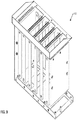
Figure 6 shows a perspective view of an IO subsystem according to one embodiment of the invention. -
Figure 7 shows a perspective view of a compute server according to one embodiment of the invention. -
Figure 8 shows a perspective view of a control server according to one embodiment of the invention. -
Figure 9 shows a perspective view of a storage chassis according to one embodiment of the invention. -
Figure 10 shows a perspective view of an Ethernet switch module according to one embodiment of the invention. -
Figure 11 shows a perspective view of a power supply unit according to one embodiment of the invention. -
Figure 12 shows a perspective view of a vibration reduction platform according to one embodiment of the invention. - Various embodiments and aspects of the inventions will be described with reference to details discussed below, and the accompanying drawings will illustrate the various embodiments. The following description and drawings are illustrative of the invention and are not to be construed as limiting the invention. Numerous specific details are described to provide a thorough understanding of various embodiments of the present invention. However, in certain instances, well-known or conventional details are not described in order to provide a concise discussion of embodiments of the present inventions.
- Reference in the specification to "one embodiment" or "an embodiment" means that a particular feature, structure, or characteristic described in conjunction with the embodiment can be included in at least one embodiment of the invention. The appearances of the phrase "in one embodiment" in various places in the specification do not necessarily all refer to the same embodiment.
- According to some embodiments, an autonomous driving hardware platform provides an integrated and compact high performance computing environment that fits in a vehicle trunk. According to one embodiment, a hardware platform includes a chassis to house a number of compartments, including a control server compartment, a compute server compartment, and an input and output (IO) subsystem compartment. The platform further includes an IO subsystem inserted into the IO subsystem compartment, a compute server inserted into the compute server compartment, and a control server inserted into the control server compartment.
- The IO subsystem includes a number of IO modules. At least some of the IO modules can be coupled to one or more sensors. The sensors can sense a surrounding environment of an autonomous vehicle and generate sensor data perceiving the surrounding environment of the autonomous vehicle. The compute server is the single computer that receives the sensor data from the IO subsystem via one or more Peripheral Component Interconnect Express (PCIe) links and makes planning and control decisions based on the sensor data for controlling the autonomous vehicle in contrast of using multiple computers connected over Ethernet. The control server then controls and drives the autonomous vehicle by sending proper control commands to the autonomous vehicle based on the planning and control decisions received from the compute server.
-
Figures 1A and1B show perspective views of a hardware platform for controlling and operating an autonomous vehicle according to one embodiment of the invention. Referring toFigure 1A , which shows a front perspective view of the platform, according to one embodiment,platform 100 includes a chassis having a frontend orfront side 101, backend or backside 102, top end ortop side 103, and a bottom end or bottom side (not shown).Frontend 101 is covered byfront panel 105 whiletop end 103 is covered bytop panel 107. In addition, both sides are covered byside panels Figure 1B ). Each of theside panels platform 100 as a portable platform. - In one embodiment, the chassis includes various compartments to store or contain various subsystems, such as, for example,
IO subsystem 111 and storage module 112 (also referred to as a storage unit) in this front perspective view as shown inFigure 1A .Top panel 107 can be removed to allowIO subsystem 111 andstorage module 112 to be inserted into or removed from the IO subsystem compartment and storage compartment respectively as shown inFigure 5 . Top panel further includes an opening or window to expose a frontend or an interface ofIO subsystem 111 andstorage module 112 upwardly, for example, to allow user accessing the components (e.g., inserting or removing an individual IO module or storage card).Front panel 105 includes one or more openings (or windows or cutouts) to expose certain connectors or interfaces ofIO subsystem 111. Further,top panel 107 includes ascreen portion 108 to for air circulation (referred to as an air intake screen) for the purpose of cooling the components contained within the chassis. - Referring now to
Figure 1B , which is a back perspective view, according one embodiment,backend 102 is covered byback panel 106 having various openings to allow certain components to be inserted into or removed from their respective compartments. In this example,platform 100 includescompute server 113 inserted into a compute server compartment,control server 114 inserted into a control server compartment, andEthernet switch module 115 inserted into an Ethernet switch compartment. In this particular embodiment, the compute server compartment and the control server compartment are positioned in a substantially horizontal orientation, as shown inFigure 5 . Thus, computeserver 113 is inserted into or removed from the compute server compartment horizontally frombackend 102. Similarly,control server 114 is inserted into or removed from the control server compartment horizontally frombackend 102. In this particular embodiment, the control server compartment is positioned above the compute server compartment. The frontends ofcompute server 113 andcontrol server 114 are exposed via the corresponding openings ofback panel 106. - In one embodiment,
Ethernet switch module 115 is inserted into or removed from the Ethernet switch compartment vertically fromtop end 103.Back panel 106 includes an opening to expose Ethernet connectors (e.g., Ethernet sockets) to allow other components such ascompute server 113 andcontrol server 114 to communicate with each other over the Ethernet. In this particular embodiment, the Ethernet switch compartment is positioned above the control server compartment.Back panel 106 further includes one or more openings to expose an interface of another side ofIO subsystem 111 to allow theIO subsystem 111 to be coupled to other components such ascompute server 113 using appropriate cables.Back panel 106 further includes one ormore screens 109 for air circulation (referred to as an air exhaustion screen) for the purpose of cooling the components contained in the chassis. - In one embodiment, the cool air is drawn into the chassis from the
air intake screen 108 fromtop end 103, travels downwardly through the air space between the components contained in the chassis (e.g.,Ethernet switch module 115,storage module 112,control server 114, and compute server 113) to exchange heat generated from the components, and exits the chassis through the screens 125-126 disposed on the frontends ofcontrol server 114 and computeserver 113. In addition, a portion of the cool air travels through a power supply unit (not shown) to exchange heat generated therein and exits theair exhaustion screen 109 to reduce the temperature of the power supply unit. -
Figure 2 shows a back view of a platform for operating an autonomous vehicle according to one embodiment of the invention. Referring toFigure 2 ,back panel 106 includes a number of openings to allow various components or subsystems to be inserted into or removed from their respective compartments. In this example, computeserver 113 can be inserted into or removed from the compute server compartment from the backend horizontally.Control server 114 can be inserted into or removed from the control server compartment from the backend horizontally. The frontend ofcompute server 113 includes various interfaces to be connected with other components including, for example, one ormore Ethernet connectors 201, universal serial bus (USB)connectors 202, andPCIe connectors 203A-203B.Figure 7 shows an example ofcompute server 113. The frontend ofcontrol server 114 also includes one ormore Ethernet connectors 204 andUSB connectors 205.Figure 8 shows an example of acontrol server 114 according to certain embodiments of the invention. - In one embodiment,
back panel 106 further includes an opening to exposeEthernet connectors 206 ofEthernet switch module 115, which allow other components to communicate with each other using Ethernet protocols. In this example,control server 114 can be coupled toEthernet switch module 115 by connecting any ofEthernet connectors 204 with any ofEthernet connectors 206 using an Ethernet cable. Similarly, computeserver 113 can be coupled toEthernet switch module 115 by connecting any ofEthernet connectors 201 with any ofEthernet connectors 206 using an Ethernet cable. As a result, computeserver 113 andcontrol server 114 can communicate with each other using Ethernet protocols.Figure 10 shows an example of an Ethernet switch module according to one embodiment. - In one embodiment,
back panel 106 further includes an opening to expose a side panel ofIO subsystem 111, where the side panel ofIO subsystem 111 includes various interfaces for accessingIO subsystem 111. In this example, referring now toFigure 2 andFigure 6 ,IO subsystem 111 includes two IO subsystem units:IO subsystem unit 111A andIO subsystem unit 111B. Each ofIO subsystem units 111A-111B contains a number of IO modules.Back panel 106 includes afirst opening 211A and asecond opening 211B to expose a side panel ofIO subsystem unit 111A andIO subsystem unit 111B, respectively. Note thatIO subsystem 111 can includes more or fewer IO subsystem units. Each ofIO subsystem units - In this example, the side panel of
IO subsystem unit 111A includes one ormore PCIe connectors 212A and the side panel ofIO subsystem unit 111B includes one ormore PCIe connectors 212B. Each of thePCIe connectors 212A-212B may be coupled to one of the IO modules contained inIO subsystem units 111A-111B. Any of the IO modules of theIO subsystem units 111A-111B can be coupled toPCIe connectors 203A-203B ofcompute server 113, such that the corresponding IO module or modules can communicate withcompute server 113 via a corresponding PCIe link. - In one embodiment,
IO subsystem unit 111A andIO subsystem unit 111B may be designed in the same or similar configuration. The frontend ofIO subsystem units 111A-111B includes a number of slots to receive a number of IO modules. The backend of theIO subsystem units 111A-111B includes a cooling fan mounted thereon to cool the temperature of the IO modules inserted therein. In one embodiment, in order to have the same side panel (e.g., the side panel havingPCIe connectors back panel 106 of the chassis), one of theIO subsystem units 111A-111B is facing upwardly and the other one of theIO subsystem units 111A-111B is facing downwardly. In this example,IO subsystem unit 211A is facing downwardly whileIO subsystem unit 211B is facing upwardly as shown inFigure 1B , while theirPCIe connectors 212A-212B are exposed throughback panel 106. As a result,PCIe connectors IO subsystem units 111A-111B can be coupled toPCIe connectors 203A-203B ofcompute server 113 via PCIe link cables on backend of the chassis. Each of the IO subsystem units are designed symmetrically so they can be mounted facing upwardly or downwardly depending on the back panel access requirements and air ventilation requirements of the IO modules. - In one embodiment, the opposite side panel of
IO subsystem 111 may include one or more sensor connectors that can be coupled to one or more sensors via sensor cables such as sensor connectors 131-132 as shown inFigure 1A . A sensor can be any one of a camera, a global positioning system (GPS), an inertial measurement unit (IMU), a radar unit, a light detection and range (LIDAR) unit, an infrared sensor, a wheel encoder, a steering sensor, a throttle sensor, a braking sensor, etc. -
Figure 3 shows a top view of a platform for operating an autonomous vehicle according to one embodiment of the invention. Referring toFigure 3 ,top panel 107 includes an opening to expose a frontend ofstorage module 112 contained in a storage compartment. In this embodiment, the storage compartment is configured as a vertical compartment.Storage module 112 can be inserted into or removed from the storage compartment from the top of the platform vertically. The frontend ofstorage module 112 includes one or more slots to receive one or more storage cards (e.g., plug-in cards) having one or more storage devices such as solid state devices.Figure 9 shows an example of a storage chassis that includes a number of storage slots to receive a number of storage cards having one or more storage devices thereon.Top panel 107 further includes an opening to expose a frontend and/or backend ofIO subsystem 111. -
Figure 4 shows a bottom view of a platform for operating an autonomous vehicle according to one embodiment of the invention. Referring toFigure 4 , the bottom panel includes an opening to expose the backend ofIO subsystem module 111A and the frontend ofIO subsystem module 111B. -
Figure 5 shows a perspective view of a chassis housing a platform for operating an autonomous vehicle according to one embodiment. Referring toFigure 5 ,chassis 500 includescompute server compartment 501,control server compartment 502,IO subsystem compartment 503, Ethernet switch compartment 504,storage compartment 505, andpower supply compartment 506. In this embodiment, computeserver compartment 501 is positioned substantially horizontally to allowcompute server 113 to slide intocompartment 501 from the backend ofchassis 500. Similarly,control server compartment 502 is positioned substantially horizontally to allowcontrol server 114 to slide intocompartment 502 from the backend ofchassis 500.Control server compartment 502 is positioned abovecompute server compartment 501. - In one embodiment,
IO subsystem compartment 503 is positioned on the opposite end ofcompute server compartment 501 andcontrol server compartment 502.IO subsystem compartment 503 is configured in a substantially vertical orientation. In this embodiment,IO subsystem compartment 503 is configured to be a vertical tunnel from the top end to the bottom end ofchassis 500.IO subsystem 111 can be deposited intoIO subsystem compartment 503 from the top end ofchassis 500. In one embodiment,top panel 107 has to be removed in order to allowIO subsystem 111 slide downwardly intoIO subsystem compartment 503. - In one embodiment, Ethernet switch compartment 504 is positioned above
control server compartment 502. In this example, Ethernet switch compartment 504 is configured in a substantially vertical orientation.Ethernet switch module 115 as shown inFigure 10 can be deposited into Ethernet switch compartment 504 from the top end ofchassis 500. Referring toFigure 10 ,Ethernet switch module 115 includes an array of Ethernet ports or connectors to allow Ethernet cables from other components to be coupled thereon.Ethernet switch module 115 further includes a vertical air tunnel, in this example, in a tubular shape, to allow the cool air received throughair intake screen 108 to travel downwardly to reachcontrol server 114 underneath. As shown inFigure 8 ,control server 114 is configured to have an open top configuration so that the cool air can reach the motherboard ofcontrol server 114 from the top. Each ofcontrol server 114 and computeserver 113 may include one or more cooling fans to draw the cool air downwardly. - Similarly,
storage compartment 505 is positioned abovecontrol server compartment 502.Figure 9 shows a perspective view of a storage chassis having one or more slots to receive one or more storage devices (e.g., solid state storage devices) to formstorage module 112. In this example, Ethernet switch compartment 504 is positioned near the backend ofchassis 500 whilestorage compartment 505 is positioned near the frontend ofchassis 500. -
Chassis 500 further includespower supply compartment 506, which is configured in a substantially vertical orientation. In this example, power supply compartment is positioned between Ethernet switch compart 504/storage compartment 505 andIO subsystem compartment 503. A power supply unit or module such as a power supply unit as shown inFigure 11 can be deposited intopower supply compartment 506 from the top ofchassis 500. The power supply unit can draw power from a vehicle battery (e.g., 12 volt DC power source) of an autonomous vehicle and regulate and distribute power to other components of the platform, such asIO subsystem 111, computeserver 113, andcontrol server 114. Ifcontrol server 114 and/or computeserver 113 are ordinary off-the-shelf computers, the power supply unit may include a DC/AC inverter to generate AC power topower control server 114 and/or computeserver 113. - In one embodiment,
platform 100 is placed in a trunk of a vehicle. As the vehicle moves, the ride may be bumpy. In order to reduce the vibration of the platform, according to one embodiment,platform 100 may be placed onto a vibration reduction platform.Figure 12 shows an example of a vibration reduction platform according to one embodiment of the invention. Referring toFigure 12 , the vibration reduction platform includes avibration reduction board 1200 supported by stands 1201-1203. Stands 1201-1203 raise theboard 1200 upwardly to leave an air space underneath theboard 1200. In addition, theboard 1200 includes openings 1211-1212 to allow air circulation exchanged withIO subsystem 111 ofplatform 100. In one embodiment, cool air is drawn from the top of the chassis throughscreen 108. The cool air travels downwardly through Ethernet switch compartment 504,storage compartment 505,control server compartment 502, computeserver compartment 501 to exchange heat generated by the corresponding components. The warm or hot air carrying the exchanged heat is let out of the chassis through the screen(s) disposed on the back panel of the chassis and/or the frontend of thecontrol server 114 and computeserver 113. - Embodiments of the present invention are not described with reference to any particular programming language. It will be appreciated that a variety of programming languages may be used to implement the teachings of embodiments of the invention as described herein.
- In the foregoing specification, embodiments of the invention have been described with reference to specific exemplary embodiments thereof. It will be evident that various modifications may be made thereto without departing from the broader spirit and scope of the invention as set forth in the following claims. The specification and drawings are, accordingly, to be regarded in an illustrative sense rather than a restrictive sense.
Claims (15)
- An apparatus for controlling and operating an autonomous vehicle, the apparatus comprising:a chassis housing a plurality of compartments, including a control server compartment, a compute server compartment, and an input and output (IO) subsystem compartment;an IO subsystem inserted into the IO subsystem compartment, the IO subsystem having a plurality of IO modules, wherein at least some of the IO modules are to be coupled to one or more sensors;a compute server inserted into the compute server compartment, wherein the compute server receives the sensor data from the IO subsystem via a plurality of Peripheral Component Interconnect Express (PCIe) links and generates planning and control data based on the sensor data for controlling the autonomous vehicle; anda control server inserted into the control server compartment coupled to the compute server via an Ethernet connection, wherein the control server controls and operates the autonomous vehicle by sending a plurality of control commands to hardware of the autonomous vehicle based on the planning and control data received from the compute server.
- The apparatus of claim 1, wherein the compute server compartment is configured in a substantially horizontal orientation, and wherein the compute server is inserted horizontally into the compute server compartment from a backend of the chassis.
- The apparatus of claim 2, wherein the control server compartment is configured in a substantially horizontal orientation, and wherein the control server is inserted horizontally into the control server compartment from the backend of the chassis;
preferably, the control server compartment is positioned above the compute server compartment. - The apparatus of claim 1, wherein the IO subsystem compartment is configured in a substantially vertical orientation, and wherein the IO subsystem is inserted vertically into the IO subsystem compartment from a top end of the chassis.
- The apparatus of claim 4, wherein the IO subsystem compartment is configured as a vertical tunnel extended from the top end of the chassis to a bottom end of the chassis, the top end and bottom end of the chassis including a top opening and a bottom opening respectively to expose a frontend and a backend of the IO subsystem.
- The apparatus of claim 5, wherein the frontend of the IO subsystem includes a plurality of IO slots to receive the plurality of IO modules respectively, and wherein the backend of the IO subsystem includes one or more cooling fans to cool a temperature of the IO modules.
- The apparatus of claim 5, wherein the IO subsystem includes a first IO subsystem unit and a second IO subsystem unit, wherein a first frontend of the first IO subsystem unit is exposed from the top end of the chassis via the vertical tunnel, and wherein a second frontend of the second IO subsystem unit is exposed from the bottom end of the chassis via the vertical tunnel.
- The apparatus of claim 5, wherein a back side of the vertical tunnel formed as a part of the backend of the chassis further comprises an opening to expose a first side panel of the IO subsystem;
preferably, the first side panel of the IO subsystem comprises a first set of PCIe connectors to allow the IO subsystem to be coupled to the compute server via one or more PCIe link cables;
more preferably, a frontend of the compute server further comprises a second set of PCIe connectors to be coupled to the first set of PCIe connectors using the PCIe link cables. - The apparatus of claim 5, wherein a front side of the vertical tunnel formed as a part of the frontend of the chassis further comprises an opening to expose a second side panel of the IO subsystem;
preferably, the second side panel of the IO subsystem comprises a set of sensor connectors disposed thereon to allow a plurality of sensors to be coupled to the IO subsystem via sensor cables. - The apparatus of claim 1, further comprising an Ethernet switch module having an Ethernet switch contained by an Ethernet switch compartment within the chassis.
- The apparatus of claim 10, wherein the Ethernet compartment is positioned above the control server compartment, and wherein the Ethernet switch module includes a first set of one or more Ethernet connectors exposed through the backend of the chassis;
preferably, the Ethernet switch module is deposited into the Ethernet compartment from the top end of the chassis. - The apparatus of claim 10, wherein a frontend of the compute server includes a second set of one or more Ethernet connectors to allow the compute server to be coupled to the first set of Ethernet connectors of the Ethernet switch module via Ethernet cables; or
wherein a frontend of the control server includes a third set of one or more Ethernet connectors to allow the control server to be coupled to the first set of Ethernet connectors of the Ethernet switch module via Ethernet cables. - The apparatus of claim 1, further comprising a storage module contained in a storage compartment within the chassis, wherein the storage module includes a plurality of storage devices to store data utilized by the control server and the compute server.
- The apparatus of claim 13, wherein the storage module is deposited into the storage compartment from the top end of the chassis, which exposes a frontend of the storage module upwardly.
- The apparatus of claim 1, further comprising a power supply unit contained by a power supply compartment within the chassis, wherein the power supply unit provides power to the control server, the compute server, and the IO subsystem,
preferably, the power supply unit is deposited into the power supply compartment from the top end of the chassis.
Applications Claiming Priority (1)
| Application Number | Priority Date | Filing Date | Title |
|---|---|---|---|
| US15/353,555 US10635621B2 (en) | 2016-11-16 | 2016-11-16 | Apparatus for controlling and operating an autonomous vehicle |
Publications (2)
| Publication Number | Publication Date |
|---|---|
| EP3324266A1 true EP3324266A1 (en) | 2018-05-23 |
| EP3324266B1 EP3324266B1 (en) | 2023-05-24 |
Family
ID=59930175
Family Applications (1)
| Application Number | Title | Priority Date | Filing Date |
|---|---|---|---|
| EP17191438.5A Active EP3324266B1 (en) | 2016-11-16 | 2017-09-15 | Apparatus for controlling and operating an autonomous vehicle |
Country Status (4)
| Country | Link |
|---|---|
| US (1) | US10635621B2 (en) |
| EP (1) | EP3324266B1 (en) |
| JP (1) | JP6483774B2 (en) |
| CN (1) | CN108076609B (en) |
Cited By (3)
| Publication number | Priority date | Publication date | Assignee | Title |
|---|---|---|---|---|
| DE102018211702A1 (en) * | 2018-07-13 | 2019-07-25 | Audi Ag | Control unit for a driver assistance system of a motor vehicle |
| DE102021120711A1 (en) | 2021-08-10 | 2023-02-16 | Kuka Deutschland Gmbh | Control box system and self-propelled vehicle with such a control box system |
| WO2024215592A1 (en) * | 2023-04-12 | 2024-10-17 | Tusimple, Inc. | Modular enclosure for an in-vehicle computer system |
Families Citing this family (7)
| Publication number | Priority date | Publication date | Assignee | Title |
|---|---|---|---|---|
| USD896218S1 (en) * | 2018-01-12 | 2020-09-15 | Siemens Aktiengesellschaft | Computer |
| US11353870B2 (en) * | 2018-12-31 | 2022-06-07 | Baidu Usa Llc | Autonomous driving computing and storage expansion device with flexible host and client configuration |
| CN112596818B (en) * | 2020-12-30 | 2023-12-05 | 上海众源网络有限公司 | Application program control method, system and device |
| CN112732033B (en) * | 2021-01-07 | 2021-08-17 | 南京维觉科技有限公司 | High-efficient heat dissipation machine case of radar |
| US12310474B2 (en) | 2021-10-08 | 2025-05-27 | Johnson & Johnson Vision Care, Inc. | Multi-material lens package |
| US20240349442A1 (en) * | 2023-04-12 | 2024-10-17 | Tusimple, Inc. | Modular enclosure for an in-vehicle computer system |
| CN116302846B (en) * | 2023-05-18 | 2023-08-18 | 苏州浪潮智能科技有限公司 | Server internal temperature control method, system, equipment, medium and server |
Citations (5)
| Publication number | Priority date | Publication date | Assignee | Title |
|---|---|---|---|---|
| EP0528168A1 (en) * | 1991-08-21 | 1993-02-24 | International Business Machines Corporation | One-piece electronic cage |
| US6208522B1 (en) * | 1999-02-12 | 2001-03-27 | Compaq Computer Corp. | Computer chassis assembly with a single center pluggable midplane board |
| US20050190536A1 (en) * | 2004-02-26 | 2005-09-01 | Microsoft Corporation | Method for expanding PC functionality while maintaining reliability and stability |
| US20100165571A1 (en) * | 2008-12-30 | 2010-07-01 | Dtech Labs, Lnc. | Mobile modular communication system |
| US20120087081A1 (en) * | 2010-10-06 | 2012-04-12 | Hon Hai Precision Industry Co., Ltd. | Computer enclosure and storage device module thereof |
Family Cites Families (15)
| Publication number | Priority date | Publication date | Assignee | Title |
|---|---|---|---|---|
| JPS57191087U (en) * | 1981-05-29 | 1982-12-03 | ||
| JP3332501B2 (en) * | 1993-10-06 | 2002-10-07 | マツダ株式会社 | Car travel control device |
| US6185098B1 (en) * | 2000-01-31 | 2001-02-06 | Chatsworth Products, Inc. | Co-location server cabinet |
| US20070099494A1 (en) * | 2005-11-02 | 2007-05-03 | Eren Niazi | Vertical patch panel |
| US7452236B2 (en) * | 2007-02-01 | 2008-11-18 | Aprius, Inc. | Cabling for rack-mount devices |
| JP5229507B2 (en) * | 2010-03-30 | 2013-07-03 | 株式会社デンソー | Vehicle distance sensor |
| US9014911B2 (en) * | 2011-11-16 | 2015-04-21 | Flextronics Ap, Llc | Street side sensors |
| US8863256B1 (en) * | 2011-01-14 | 2014-10-14 | Cisco Technology, Inc. | System and method for enabling secure transactions using flexible identity management in a vehicular environment |
| KR101883475B1 (en) * | 2013-02-28 | 2018-07-31 | 한화지상방산 주식회사 | Mini Integrated-control device |
| US9524005B2 (en) * | 2013-11-13 | 2016-12-20 | W.W. Grainger, Inc. | Data center server racks |
| SG2013094396A (en) * | 2013-12-19 | 2015-07-30 | Rockwell Automation Asia Pacific Business Ctr Pte Ltd | Slice-io housing with side ventilation |
| JP2015170678A (en) * | 2014-03-06 | 2015-09-28 | 株式会社東芝 | Electronic equipment casing and blower cover |
| US10226982B2 (en) * | 2015-04-29 | 2019-03-12 | International Business Machines Corporation | Automatic vehicle climate control based on predicted air quality |
| CN205622767U (en) * | 2016-03-31 | 2016-10-05 | 淮南师范学院 | Wireless video monitor system of intelligence car based on ARM |
| US9981657B2 (en) * | 2016-04-14 | 2018-05-29 | Ford Global Technologies, Llc | Autonomous vehicle parking and transition to manual control |
-
2016
- 2016-11-16 US US15/353,555 patent/US10635621B2/en active Active
-
2017
- 2017-09-13 CN CN201710823898.6A patent/CN108076609B/en active Active
- 2017-09-15 EP EP17191438.5A patent/EP3324266B1/en active Active
- 2017-09-15 JP JP2017177317A patent/JP6483774B2/en not_active Expired - Fee Related
Patent Citations (5)
| Publication number | Priority date | Publication date | Assignee | Title |
|---|---|---|---|---|
| EP0528168A1 (en) * | 1991-08-21 | 1993-02-24 | International Business Machines Corporation | One-piece electronic cage |
| US6208522B1 (en) * | 1999-02-12 | 2001-03-27 | Compaq Computer Corp. | Computer chassis assembly with a single center pluggable midplane board |
| US20050190536A1 (en) * | 2004-02-26 | 2005-09-01 | Microsoft Corporation | Method for expanding PC functionality while maintaining reliability and stability |
| US20100165571A1 (en) * | 2008-12-30 | 2010-07-01 | Dtech Labs, Lnc. | Mobile modular communication system |
| US20120087081A1 (en) * | 2010-10-06 | 2012-04-12 | Hon Hai Precision Industry Co., Ltd. | Computer enclosure and storage device module thereof |
Non-Patent Citations (1)
| Title |
|---|
| ANDREAS GEIGER ET AL: "Team AnnieWAY's Entry to the 2011 Grand Cooperative Driving Challenge", IEEE TRANSACTIONS ON INTELLIGENT TRANSPORTATION SYSTEMS, IEEE, PISCATAWAY, NJ, USA, vol. 13, no. 3, 28 August 2012 (2012-08-28), pages 1008 - 1017, XP011472560, ISSN: 1524-9050, DOI: 10.1109/TITS.2012.2189882 * |
Cited By (4)
| Publication number | Priority date | Publication date | Assignee | Title |
|---|---|---|---|---|
| DE102018211702A1 (en) * | 2018-07-13 | 2019-07-25 | Audi Ag | Control unit for a driver assistance system of a motor vehicle |
| DE102021120711A1 (en) | 2021-08-10 | 2023-02-16 | Kuka Deutschland Gmbh | Control box system and self-propelled vehicle with such a control box system |
| WO2023016906A1 (en) | 2021-08-10 | 2023-02-16 | Kuka Deutschland Gmbh | Control housing system and self-driving vehicle having a control housing system of this type |
| WO2024215592A1 (en) * | 2023-04-12 | 2024-10-17 | Tusimple, Inc. | Modular enclosure for an in-vehicle computer system |
Also Published As
| Publication number | Publication date |
|---|---|
| EP3324266B1 (en) | 2023-05-24 |
| CN108076609A (en) | 2018-05-25 |
| US20180137076A1 (en) | 2018-05-17 |
| US10635621B2 (en) | 2020-04-28 |
| CN108076609B (en) | 2020-06-23 |
| JP6483774B2 (en) | 2019-03-13 |
| JP2018081678A (en) | 2018-05-24 |
Similar Documents
| Publication | Publication Date | Title |
|---|---|---|
| EP3324266B1 (en) | Apparatus for controlling and operating an autonomous vehicle | |
| US9802321B2 (en) | Mini integrated control device | |
| CN104136311B (en) | Vehicle control system | |
| US20050038564A1 (en) | Robot with removable mounting elements | |
| US11465544B2 (en) | Vehicle | |
| US10440863B1 (en) | System and method to enable large-scale data computation during transportation | |
| US10314206B1 (en) | Modulating AHU VS RAM air cooling, based on vehicular velocity | |
| EP3813229A1 (en) | Vehicle battery charging apparatus | |
| CN111837112B (en) | Resource sharing between vehicle applications connected via bus | |
| CN113287131A (en) | Logistics system for transporting goods by vehicle, method for operating logistics system and vehicle | |
| US20210162835A1 (en) | Temperature regulation of automated driving system computer using vehicle air conditioning system | |
| US20210162588A1 (en) | Robot control device and robot including the same | |
| CN107867395B (en) | Host structure assembly and remote control mobile device using same | |
| US20190281340A1 (en) | Full immersion video system in a multi-passenger vehicle | |
| US20240198829A1 (en) | Access floor equipped with a system for wireless charging of a robot and a building including same | |
| US12342497B2 (en) | Modular cold plate for electronic control module | |
| US11934574B2 (en) | Modifying vehicle display parameters using operator gaze | |
| CN109017629A (en) | Automatic driving vehicle and its card insertion type structure, module and vehicle computing platform | |
| US20240147675A1 (en) | Electronic control module cooling system | |
| CN117729753A (en) | Vehicle control system | |
| US12077110B2 (en) | Consolidated electronics packaging | |
| CN211493939U (en) | Unmanned vehicle and locomotive module thereof | |
| CN114435270A (en) | Vehicle integrated computer | |
| US10368469B1 (en) | Pre-heating supply air for IT equipment by utilizing transport vehicle residual heat | |
| WO2023278006A1 (en) | Consolidated electronics packaging |
Legal Events
| Date | Code | Title | Description |
|---|---|---|---|
| PUAI | Public reference made under article 153(3) epc to a published international application that has entered the european phase |
Free format text: ORIGINAL CODE: 0009012 |
|
| STAA | Information on the status of an ep patent application or granted ep patent |
Free format text: STATUS: REQUEST FOR EXAMINATION WAS MADE |
|
| 17P | Request for examination filed |
Effective date: 20170915 |
|
| AK | Designated contracting states |
Kind code of ref document: A1 Designated state(s): AL AT BE BG CH CY CZ DE DK EE ES FI FR GB GR HR HU IE IS IT LI LT LU LV MC MK MT NL NO PL PT RO RS SE SI SK SM TR |
|
| AX | Request for extension of the european patent |
Extension state: BA ME |
|
| STAA | Information on the status of an ep patent application or granted ep patent |
Free format text: STATUS: EXAMINATION IS IN PROGRESS |
|
| 17Q | First examination report despatched |
Effective date: 20201012 |
|
| REG | Reference to a national code |
Ref country code: DE Ref legal event code: R079 Ref document number: 602017068960 Country of ref document: DE Free format text: PREVIOUS MAIN CLASS: G06F0001180000 Ipc: G06F0001200000 |
|
| RIC1 | Information provided on ipc code assigned before grant |
Ipc: G06F 13/42 20060101ALN20221021BHEP Ipc: G06F 13/40 20060101ALN20221021BHEP Ipc: G06F 1/18 20060101ALI20221021BHEP Ipc: G06F 1/20 20060101AFI20221021BHEP |
|
| GRAP | Despatch of communication of intention to grant a patent |
Free format text: ORIGINAL CODE: EPIDOSNIGR1 |
|
| STAA | Information on the status of an ep patent application or granted ep patent |
Free format text: STATUS: GRANT OF PATENT IS INTENDED |
|
| INTG | Intention to grant announced |
Effective date: 20230104 |
|
| GRAS | Grant fee paid |
Free format text: ORIGINAL CODE: EPIDOSNIGR3 |
|
| GRAA | (expected) grant |
Free format text: ORIGINAL CODE: 0009210 |
|
| STAA | Information on the status of an ep patent application or granted ep patent |
Free format text: STATUS: THE PATENT HAS BEEN GRANTED |
|
| AK | Designated contracting states |
Kind code of ref document: B1 Designated state(s): AL AT BE BG CH CY CZ DE DK EE ES FI FR GB GR HR HU IE IS IT LI LT LU LV MC MK MT NL NO PL PT RO RS SE SI SK SM TR |
|
| REG | Reference to a national code |
Ref country code: GB Ref legal event code: FG4D |
|
| REG | Reference to a national code |
Ref country code: CH Ref legal event code: EP |
|
| REG | Reference to a national code |
Ref country code: DE Ref legal event code: R096 Ref document number: 602017068960 Country of ref document: DE |
|
| REG | Reference to a national code |
Ref country code: AT Ref legal event code: REF Ref document number: 1569926 Country of ref document: AT Kind code of ref document: T Effective date: 20230615 |
|
| REG | Reference to a national code |
Ref country code: IE Ref legal event code: FG4D |
|
| REG | Reference to a national code |
Ref country code: LT Ref legal event code: MG9D |
|
| REG | Reference to a national code |
Ref country code: NL Ref legal event code: MP Effective date: 20230524 |
|
| REG | Reference to a national code |
Ref country code: AT Ref legal event code: MK05 Ref document number: 1569926 Country of ref document: AT Kind code of ref document: T Effective date: 20230524 |
|
| PG25 | Lapsed in a contracting state [announced via postgrant information from national office to epo] |
Ref country code: SE Free format text: LAPSE BECAUSE OF FAILURE TO SUBMIT A TRANSLATION OF THE DESCRIPTION OR TO PAY THE FEE WITHIN THE PRESCRIBED TIME-LIMIT Effective date: 20230524 Ref country code: PT Free format text: LAPSE BECAUSE OF FAILURE TO SUBMIT A TRANSLATION OF THE DESCRIPTION OR TO PAY THE FEE WITHIN THE PRESCRIBED TIME-LIMIT Effective date: 20230925 Ref country code: NO Free format text: LAPSE BECAUSE OF FAILURE TO SUBMIT A TRANSLATION OF THE DESCRIPTION OR TO PAY THE FEE WITHIN THE PRESCRIBED TIME-LIMIT Effective date: 20230824 Ref country code: NL Free format text: LAPSE BECAUSE OF FAILURE TO SUBMIT A TRANSLATION OF THE DESCRIPTION OR TO PAY THE FEE WITHIN THE PRESCRIBED TIME-LIMIT Effective date: 20230524 Ref country code: ES Free format text: LAPSE BECAUSE OF FAILURE TO SUBMIT A TRANSLATION OF THE DESCRIPTION OR TO PAY THE FEE WITHIN THE PRESCRIBED TIME-LIMIT Effective date: 20230524 Ref country code: AT Free format text: LAPSE BECAUSE OF FAILURE TO SUBMIT A TRANSLATION OF THE DESCRIPTION OR TO PAY THE FEE WITHIN THE PRESCRIBED TIME-LIMIT Effective date: 20230524 |
|
| PG25 | Lapsed in a contracting state [announced via postgrant information from national office to epo] |
Ref country code: RS Free format text: LAPSE BECAUSE OF FAILURE TO SUBMIT A TRANSLATION OF THE DESCRIPTION OR TO PAY THE FEE WITHIN THE PRESCRIBED TIME-LIMIT Effective date: 20230524 Ref country code: PL Free format text: LAPSE BECAUSE OF FAILURE TO SUBMIT A TRANSLATION OF THE DESCRIPTION OR TO PAY THE FEE WITHIN THE PRESCRIBED TIME-LIMIT Effective date: 20230524 Ref country code: LV Free format text: LAPSE BECAUSE OF FAILURE TO SUBMIT A TRANSLATION OF THE DESCRIPTION OR TO PAY THE FEE WITHIN THE PRESCRIBED TIME-LIMIT Effective date: 20230524 Ref country code: LT Free format text: LAPSE BECAUSE OF FAILURE TO SUBMIT A TRANSLATION OF THE DESCRIPTION OR TO PAY THE FEE WITHIN THE PRESCRIBED TIME-LIMIT Effective date: 20230524 Ref country code: IS Free format text: LAPSE BECAUSE OF FAILURE TO SUBMIT A TRANSLATION OF THE DESCRIPTION OR TO PAY THE FEE WITHIN THE PRESCRIBED TIME-LIMIT Effective date: 20230924 Ref country code: HR Free format text: LAPSE BECAUSE OF FAILURE TO SUBMIT A TRANSLATION OF THE DESCRIPTION OR TO PAY THE FEE WITHIN THE PRESCRIBED TIME-LIMIT Effective date: 20230524 Ref country code: GR Free format text: LAPSE BECAUSE OF FAILURE TO SUBMIT A TRANSLATION OF THE DESCRIPTION OR TO PAY THE FEE WITHIN THE PRESCRIBED TIME-LIMIT Effective date: 20230825 |
|
| PG25 | Lapsed in a contracting state [announced via postgrant information from national office to epo] |
Ref country code: FI Free format text: LAPSE BECAUSE OF FAILURE TO SUBMIT A TRANSLATION OF THE DESCRIPTION OR TO PAY THE FEE WITHIN THE PRESCRIBED TIME-LIMIT Effective date: 20230524 |
|
| PG25 | Lapsed in a contracting state [announced via postgrant information from national office to epo] |
Ref country code: SK Free format text: LAPSE BECAUSE OF FAILURE TO SUBMIT A TRANSLATION OF THE DESCRIPTION OR TO PAY THE FEE WITHIN THE PRESCRIBED TIME-LIMIT Effective date: 20230524 |
|
| PG25 | Lapsed in a contracting state [announced via postgrant information from national office to epo] |
Ref country code: SM Free format text: LAPSE BECAUSE OF FAILURE TO SUBMIT A TRANSLATION OF THE DESCRIPTION OR TO PAY THE FEE WITHIN THE PRESCRIBED TIME-LIMIT Effective date: 20230524 Ref country code: SK Free format text: LAPSE BECAUSE OF FAILURE TO SUBMIT A TRANSLATION OF THE DESCRIPTION OR TO PAY THE FEE WITHIN THE PRESCRIBED TIME-LIMIT Effective date: 20230524 Ref country code: RO Free format text: LAPSE BECAUSE OF FAILURE TO SUBMIT A TRANSLATION OF THE DESCRIPTION OR TO PAY THE FEE WITHIN THE PRESCRIBED TIME-LIMIT Effective date: 20230524 Ref country code: EE Free format text: LAPSE BECAUSE OF FAILURE TO SUBMIT A TRANSLATION OF THE DESCRIPTION OR TO PAY THE FEE WITHIN THE PRESCRIBED TIME-LIMIT Effective date: 20230524 Ref country code: DK Free format text: LAPSE BECAUSE OF FAILURE TO SUBMIT A TRANSLATION OF THE DESCRIPTION OR TO PAY THE FEE WITHIN THE PRESCRIBED TIME-LIMIT Effective date: 20230524 Ref country code: CZ Free format text: LAPSE BECAUSE OF FAILURE TO SUBMIT A TRANSLATION OF THE DESCRIPTION OR TO PAY THE FEE WITHIN THE PRESCRIBED TIME-LIMIT Effective date: 20230524 |
|
| REG | Reference to a national code |
Ref country code: DE Ref legal event code: R097 Ref document number: 602017068960 Country of ref document: DE |
|
| PLBE | No opposition filed within time limit |
Free format text: ORIGINAL CODE: 0009261 |
|
| STAA | Information on the status of an ep patent application or granted ep patent |
Free format text: STATUS: NO OPPOSITION FILED WITHIN TIME LIMIT |
|
| REG | Reference to a national code |
Ref country code: CH Ref legal event code: PL |
|
| 26N | No opposition filed |
Effective date: 20240227 |
|
| PG25 | Lapsed in a contracting state [announced via postgrant information from national office to epo] |
Ref country code: SI Free format text: LAPSE BECAUSE OF FAILURE TO SUBMIT A TRANSLATION OF THE DESCRIPTION OR TO PAY THE FEE WITHIN THE PRESCRIBED TIME-LIMIT Effective date: 20230524 |
|
| PG25 | Lapsed in a contracting state [announced via postgrant information from national office to epo] |
Ref country code: LU Free format text: LAPSE BECAUSE OF NON-PAYMENT OF DUE FEES Effective date: 20230915 |
|
| REG | Reference to a national code |
Ref country code: BE Ref legal event code: MM Effective date: 20230930 |
|
| GBPC | Gb: european patent ceased through non-payment of renewal fee |
Effective date: 20230915 |
|
| PG25 | Lapsed in a contracting state [announced via postgrant information from national office to epo] |
Ref country code: SI Free format text: LAPSE BECAUSE OF FAILURE TO SUBMIT A TRANSLATION OF THE DESCRIPTION OR TO PAY THE FEE WITHIN THE PRESCRIBED TIME-LIMIT Effective date: 20230524 Ref country code: LU Free format text: LAPSE BECAUSE OF NON-PAYMENT OF DUE FEES Effective date: 20230915 Ref country code: IT Free format text: LAPSE BECAUSE OF FAILURE TO SUBMIT A TRANSLATION OF THE DESCRIPTION OR TO PAY THE FEE WITHIN THE PRESCRIBED TIME-LIMIT Effective date: 20230524 Ref country code: MC Free format text: LAPSE BECAUSE OF FAILURE TO SUBMIT A TRANSLATION OF THE DESCRIPTION OR TO PAY THE FEE WITHIN THE PRESCRIBED TIME-LIMIT Effective date: 20230524 |
|
| REG | Reference to a national code |
Ref country code: IE Ref legal event code: MM4A |
|
| PG25 | Lapsed in a contracting state [announced via postgrant information from national office to epo] |
Ref country code: IE Free format text: LAPSE BECAUSE OF NON-PAYMENT OF DUE FEES Effective date: 20230915 |
|
| PG25 | Lapsed in a contracting state [announced via postgrant information from national office to epo] |
Ref country code: GB Free format text: LAPSE BECAUSE OF NON-PAYMENT OF DUE FEES Effective date: 20230915 |
|
| PG25 | Lapsed in a contracting state [announced via postgrant information from national office to epo] |
Ref country code: CH Free format text: LAPSE BECAUSE OF NON-PAYMENT OF DUE FEES Effective date: 20230930 |
|
| PG25 | Lapsed in a contracting state [announced via postgrant information from national office to epo] |
Ref country code: IE Free format text: LAPSE BECAUSE OF NON-PAYMENT OF DUE FEES Effective date: 20230915 Ref country code: GB Free format text: LAPSE BECAUSE OF NON-PAYMENT OF DUE FEES Effective date: 20230915 Ref country code: CH Free format text: LAPSE BECAUSE OF NON-PAYMENT OF DUE FEES Effective date: 20230930 |
|
| PG25 | Lapsed in a contracting state [announced via postgrant information from national office to epo] |
Ref country code: BE Free format text: LAPSE BECAUSE OF NON-PAYMENT OF DUE FEES Effective date: 20230930 |
|
| PG25 | Lapsed in a contracting state [announced via postgrant information from national office to epo] |
Ref country code: BG Free format text: LAPSE BECAUSE OF FAILURE TO SUBMIT A TRANSLATION OF THE DESCRIPTION OR TO PAY THE FEE WITHIN THE PRESCRIBED TIME-LIMIT Effective date: 20230524 |
|
| PG25 | Lapsed in a contracting state [announced via postgrant information from national office to epo] |
Ref country code: BG Free format text: LAPSE BECAUSE OF FAILURE TO SUBMIT A TRANSLATION OF THE DESCRIPTION OR TO PAY THE FEE WITHIN THE PRESCRIBED TIME-LIMIT Effective date: 20230524 |
|
| PG25 | Lapsed in a contracting state [announced via postgrant information from national office to epo] |
Ref country code: CY Free format text: LAPSE BECAUSE OF FAILURE TO SUBMIT A TRANSLATION OF THE DESCRIPTION OR TO PAY THE FEE WITHIN THE PRESCRIBED TIME-LIMIT; INVALID AB INITIO Effective date: 20170915 |
|
| PG25 | Lapsed in a contracting state [announced via postgrant information from national office to epo] |
Ref country code: HU Free format text: LAPSE BECAUSE OF FAILURE TO SUBMIT A TRANSLATION OF THE DESCRIPTION OR TO PAY THE FEE WITHIN THE PRESCRIBED TIME-LIMIT; INVALID AB INITIO Effective date: 20170915 |
|
| PGFP | Annual fee paid to national office [announced via postgrant information from national office to epo] |
Ref country code: DE Payment date: 20250919 Year of fee payment: 9 |
|
| PGFP | Annual fee paid to national office [announced via postgrant information from national office to epo] |
Ref country code: FR Payment date: 20250728 Year of fee payment: 9 |
|
| PG25 | Lapsed in a contracting state [announced via postgrant information from national office to epo] |
Ref country code: TR Free format text: LAPSE BECAUSE OF FAILURE TO SUBMIT A TRANSLATION OF THE DESCRIPTION OR TO PAY THE FEE WITHIN THE PRESCRIBED TIME-LIMIT Effective date: 20230524 |