EP3324244A1 - Development device, process cartridge, and image forming apparatus - Google Patents
Development device, process cartridge, and image forming apparatus Download PDFInfo
- Publication number
- EP3324244A1 EP3324244A1 EP17201716.2A EP17201716A EP3324244A1 EP 3324244 A1 EP3324244 A1 EP 3324244A1 EP 17201716 A EP17201716 A EP 17201716A EP 3324244 A1 EP3324244 A1 EP 3324244A1
- Authority
- EP
- European Patent Office
- Prior art keywords
- contact point
- development
- cartridge
- development device
- developer
- Prior art date
- Legal status (The legal status is an assumption and is not a legal conclusion. Google has not performed a legal analysis and makes no representation as to the accuracy of the status listed.)
- Granted
Links
- 238000011161 development Methods 0.000 title claims abstract description 189
- 238000000034 method Methods 0.000 title claims abstract description 46
- 230000008569 process Effects 0.000 title claims abstract description 41
- 238000003780 insertion Methods 0.000 claims abstract description 21
- 230000037431 insertion Effects 0.000 claims abstract description 21
- 229920005989 resin Polymers 0.000 claims description 62
- 239000011347 resin Substances 0.000 claims description 62
- 238000001514 detection method Methods 0.000 claims description 32
- 230000008859 change Effects 0.000 claims description 3
- 238000004140 cleaning Methods 0.000 description 46
- 238000003825 pressing Methods 0.000 description 40
- 239000000463 material Substances 0.000 description 26
- 239000002699 waste material Substances 0.000 description 21
- 238000003860 storage Methods 0.000 description 19
- 238000011144 upstream manufacturing Methods 0.000 description 14
- 238000004519 manufacturing process Methods 0.000 description 9
- 238000000465 moulding Methods 0.000 description 9
- 230000002093 peripheral effect Effects 0.000 description 7
- 238000012546 transfer Methods 0.000 description 7
- 239000005038 ethylene vinyl acetate Substances 0.000 description 6
- 238000002347 injection Methods 0.000 description 6
- 239000007924 injection Substances 0.000 description 6
- 229920001200 poly(ethylene-vinyl acetate) Polymers 0.000 description 6
- 238000007789 sealing Methods 0.000 description 6
- 230000001105 regulatory effect Effects 0.000 description 5
- 230000007423 decrease Effects 0.000 description 4
- 238000012545 processing Methods 0.000 description 4
- 238000010438 heat treatment Methods 0.000 description 3
- 238000012423 maintenance Methods 0.000 description 3
- 239000011800 void material Substances 0.000 description 3
- 239000006229 carbon black Substances 0.000 description 2
- 230000003247 decreasing effect Effects 0.000 description 2
- 230000000704 physical effect Effects 0.000 description 2
- 239000004698 Polyethylene Substances 0.000 description 1
- 239000004793 Polystyrene Substances 0.000 description 1
- 239000000853 adhesive Substances 0.000 description 1
- 230000001070 adhesive effect Effects 0.000 description 1
- 230000009286 beneficial effect Effects 0.000 description 1
- 230000033228 biological regulation Effects 0.000 description 1
- 239000004020 conductor Substances 0.000 description 1
- 239000013013 elastic material Substances 0.000 description 1
- 230000009477 glass transition Effects 0.000 description 1
- 238000000691 measurement method Methods 0.000 description 1
- 238000012986 modification Methods 0.000 description 1
- 230000004048 modification Effects 0.000 description 1
- 239000002985 plastic film Substances 0.000 description 1
- -1 polyethylene Polymers 0.000 description 1
- 229920000573 polyethylene Polymers 0.000 description 1
- 238000003466 welding Methods 0.000 description 1
Images


Classifications
-
- G—PHYSICS
- G03—PHOTOGRAPHY; CINEMATOGRAPHY; ANALOGOUS TECHNIQUES USING WAVES OTHER THAN OPTICAL WAVES; ELECTROGRAPHY; HOLOGRAPHY
- G03G—ELECTROGRAPHY; ELECTROPHOTOGRAPHY; MAGNETOGRAPHY
- G03G21/00—Arrangements not provided for by groups G03G13/00 - G03G19/00, e.g. cleaning, elimination of residual charge
- G03G21/16—Mechanical means for facilitating the maintenance of the apparatus, e.g. modular arrangements
- G03G21/1642—Mechanical means for facilitating the maintenance of the apparatus, e.g. modular arrangements for connecting the different parts of the apparatus
- G03G21/1652—Electrical connection means
-
- G—PHYSICS
- G03—PHOTOGRAPHY; CINEMATOGRAPHY; ANALOGOUS TECHNIQUES USING WAVES OTHER THAN OPTICAL WAVES; ELECTROGRAPHY; HOLOGRAPHY
- G03G—ELECTROGRAPHY; ELECTROPHOTOGRAPHY; MAGNETOGRAPHY
- G03G15/00—Apparatus for electrographic processes using a charge pattern
- G03G15/06—Apparatus for electrographic processes using a charge pattern for developing
- G03G15/08—Apparatus for electrographic processes using a charge pattern for developing using a solid developer, e.g. powder developer
- G03G15/0822—Arrangements for preparing, mixing, supplying or dispensing developer
- G03G15/0848—Arrangements for testing or measuring developer properties or quality, e.g. charge, size, flowability
- G03G15/0856—Detection or control means for the developer level
- G03G15/086—Detection or control means for the developer level the level being measured by electro-magnetic means
-
- G—PHYSICS
- G03—PHOTOGRAPHY; CINEMATOGRAPHY; ANALOGOUS TECHNIQUES USING WAVES OTHER THAN OPTICAL WAVES; ELECTROGRAPHY; HOLOGRAPHY
- G03G—ELECTROGRAPHY; ELECTROPHOTOGRAPHY; MAGNETOGRAPHY
- G03G21/00—Arrangements not provided for by groups G03G13/00 - G03G19/00, e.g. cleaning, elimination of residual charge
- G03G21/16—Mechanical means for facilitating the maintenance of the apparatus, e.g. modular arrangements
- G03G21/1661—Mechanical means for facilitating the maintenance of the apparatus, e.g. modular arrangements means for handling parts of the apparatus in the apparatus
- G03G21/1676—Mechanical means for facilitating the maintenance of the apparatus, e.g. modular arrangements means for handling parts of the apparatus in the apparatus for the developer unit
-
- G—PHYSICS
- G03—PHOTOGRAPHY; CINEMATOGRAPHY; ANALOGOUS TECHNIQUES USING WAVES OTHER THAN OPTICAL WAVES; ELECTROGRAPHY; HOLOGRAPHY
- G03G—ELECTROGRAPHY; ELECTROPHOTOGRAPHY; MAGNETOGRAPHY
- G03G21/00—Arrangements not provided for by groups G03G13/00 - G03G19/00, e.g. cleaning, elimination of residual charge
- G03G21/16—Mechanical means for facilitating the maintenance of the apparatus, e.g. modular arrangements
- G03G21/18—Mechanical means for facilitating the maintenance of the apparatus, e.g. modular arrangements using a processing cartridge, whereby the process cartridge comprises at least two image processing means in a single unit
- G03G21/1803—Arrangements or disposition of the complete process cartridge or parts thereof
- G03G21/1817—Arrangements or disposition of the complete process cartridge or parts thereof having a submodular arrangement
- G03G21/1821—Arrangements or disposition of the complete process cartridge or parts thereof having a submodular arrangement means for connecting the different parts of the process cartridge, e.g. attachment, positioning of parts with each other, pressure/distance regulation
-
- G—PHYSICS
- G03—PHOTOGRAPHY; CINEMATOGRAPHY; ANALOGOUS TECHNIQUES USING WAVES OTHER THAN OPTICAL WAVES; ELECTROGRAPHY; HOLOGRAPHY
- G03G—ELECTROGRAPHY; ELECTROPHOTOGRAPHY; MAGNETOGRAPHY
- G03G21/00—Arrangements not provided for by groups G03G13/00 - G03G19/00, e.g. cleaning, elimination of residual charge
- G03G21/16—Mechanical means for facilitating the maintenance of the apparatus, e.g. modular arrangements
- G03G21/18—Mechanical means for facilitating the maintenance of the apparatus, e.g. modular arrangements using a processing cartridge, whereby the process cartridge comprises at least two image processing means in a single unit
- G03G21/1839—Means for handling the process cartridge in the apparatus body
- G03G21/1867—Means for handling the process cartridge in the apparatus body for electrically connecting the process cartridge to the apparatus, electrical connectors, power supply
- G03G21/1871—Means for handling the process cartridge in the apparatus body for electrically connecting the process cartridge to the apparatus, electrical connectors, power supply associated with a positioning function
Definitions
- the present invention relates to a development device, a process cartridge, and an image forming apparatus.
- image forming apparatus refers to an apparatus which forms images on recording materials.
- process cartridge refers to a process cartridge including at least an image carrying member.
- a process cartridge is a cartridge in which a charging unit, a development unit, a cleaning unit, and an image carrying member are integrated and which is attachable to (or insertable into) and removable from the main body of an image forming apparatus.
- development device refers to a development device including at least a developer carrying member.
- a development device is a development device in which a developer carrying member and a development frame for supporting the developer carrying member are integrated and which is attachable to (or insertable into) and removable from the main body of an image forming apparatus.
- Examples of an electrophotographic image forming apparatus include copying machines, light-emitting diode (LED) printers, laser printers, and facsimile apparatuses.
- LED light-emitting diode
- Examples of an electrophotographic image forming apparatus include copying machines, light-emitting diode (LED) printers, laser printers, and facsimile apparatuses.
- an electrophotographic photosensitive member i.e., photosensitive drum, which is an image carrying member and is in general in the shape of a drum
- image forming apparatus an electrophotographic photosensitive member, i.e., photosensitive drum, which is an image carrying member and is in general in the shape of a drum
- the charged photosensitive drum is selectively exposed to form an electrostatic latent image (electrostatic image) on the photosensitive drum.
- the electrostatic latent image formed on the photosensitive drum is developed with a toner, which is developer, to form a toner image.
- the toner image formed on the photosensitive drum is transferred onto a recording material such as a recording sheet or plastic sheet, and the toner image transferred on the recording material is heated and pressed so that the toner image is fixed to the recording material. In this way, an image is recorded.
- This process cartridge method enables users to conduct maintenance of an apparatus on their own, so operability is improved significantly, and an image forming apparatus with excellent usability is provided. For this reason, the process cartridge method is widely used in image forming apparatuses.
- Japanese Patent Application Laid-Open No. 2015-34984 discusses a configuration of detecting an amount of remaining toner using a developer carrying member and a conductive member.
- the direction of a rotation axis line of an electrophotographic photosensitive drum which is an image carrying member is defined as a lengthwise direction.
- the direction of a rotation axis line of a developer carrying member is parallel to the direction of the rotation axis line of the image carrying member, so the direction of the rotation axis line of a development roller (or development sleeve) which is the developer carrying member is also defined as the lengthwise direction.
- the side of the electrophotographic photosensitive drum that receives a driving force from the main body of an image forming apparatus is defined as a driving side, and the side opposite to the driving side is defined as a non-driving side.
- Fig. 2 is a cross sectional view illustrating the main body (hereinafter, referred to as "apparatus body A") of an electrophotographic image forming apparatus (hereinafter, referred to as “image forming apparatus”) and a process cartridge (hereinafter, referred to as “cartridge B”) according to a first exemplary embodiment of the present invention.
- apparatus body A an electrophotographic image forming apparatus
- carrier B a process cartridge
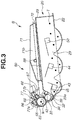
- Fig. 3 is a cross sectional view illustrating the cartridge B.
- the apparatus body A corresponds to the electrophotographic image forming apparatus that does not include the cartridge B. While the cartridge B according to the present exemplary embodiment is a process cartridge, the cartridge B can be a development device. In a case in which the development device is independently attachable to (or insertable into) and removable from the apparatus body, the apparatus body A corresponds to the image forming apparatus that does not include the development device.
- the image forming apparatus illustrated in Fig. 2 is an electrophotographic laser beam printer in which the cartridge B is attachable to (or insertable into) and removable from the apparatus body A.
- an exposure device 3 laser scanner unit
- a sheet tray 4 is disposed below the cartridge B.
- the sheet tray 4 stores recording materials (hereinafter, referred to as "sheet material P") on which images are to be formed.
- the apparatus body A includes a pickup roller 5a, a pair of sheet feeding rollers 5b, a pair of sheet conveying rollers 5c, a transfer guide 6, a transfer roller 7, a conveyance guide 8, a fixing device 9, a pair of sheet discharge rollers 10, a sheet discharge tray 11, etc. disposed sequentially along a conveyance direction D in which the sheet material P is conveyed.
- the fixing device 9 includes a heating roller 9a and a pressing roller 9b.
- drum 62 Based on a print start signal, the electrophotographic photosensitive drum 62 (hereinafter, referred to as "drum 62") is driven and rotated at a predetermined circumferential velocity (processing speed) in the direction of an arrow R.
- a charging roller 66 which is a charging member and to which a bias voltage is applied is brought into contact with the outer peripheral surface of the drum 62 to uniformly and evenly charge the outer peripheral surface of the drum 62.
- the exposure device 3 outputs laser light L corresponding to image information.
- the laser light L passes through a laser opening 71h in a cleaning housing 71 of the cartridge B and scans and exposes the outer peripheral surface of the drum 62. In this way, an electrostatic latent image corresponding to the image information is formed on the outer peripheral surface of the drum 62.
- a first conveyance member 43, a second conveyance member 44, and a third conveyance member 50 are rotated to agitate toner T in a toner chamber 29 and convey the toner T to a toner supply chamber 28 in a development unit 20 which is the development device, as illustrated in Fig. 3 .
- the first conveyance member 43, the second conveyance member 44, and the third conveyance member 50 include a shaft portion and a sheet-shaped conveyance portion, and the sheet-shaped conveyance portion is attached to the shaft portion. As the shaft portion is rotated, the sheet-shaped conveyance portion is also rotated, and the toner T is pushed by the sheet and conveyed.
- the shaft portion of the closest one of the first conveyance member 43, the second conveyance member 44, and the third conveyance member 50 to the development roller is located immediately above a position between first and second electrode plates when viewed from the lengthwise direction of the development roller.
- the first conveyance member 43, the second conveyance member 44, and the third conveyance member 50 are disposed in order from the developer carrying member side.
- the toner chamber 29 and the toner supply chamber 28 include a housing. According to the present exemplary embodiment, two housings, namely, first and second housings, are welded to form the toner chamber 29 and the toner supply chamber 28.
- the toner T which is developer is borne on the surface of a development roller 32, which is the developer carrying member, by a magnetic force of a magnet roller 34 (stationary magnet).
- the layer thickness of the toner T on the peripheral surface of the development roller 32 is regulated by a development blade 42 which is a developer layer regulation member.
- the toner T is transferred onto the drum 62 according to the electrostatic image or electrostatic latent image and visualized as a toner image which is a developer image.
- the sheet material P stored in a lower portion of the apparatus body A is conveyed from the sheet tray 4 by the pickup roller 5a, the pair of sheet feeding rollers 5b, and the pair of sheet conveying rollers 5c in synchronization with the timing of output of the laser light L. Then, the sheet material P is conveyed through the transfer guide 6 to a transfer position between the drum 62 and the transfer roller 7. At the transfer position, the toner image is sequentially transferred from the drum 62 onto the sheet material P.
- the sheet material P with the transferred toner image is separated from the drum 62 and conveyed along the conveyance guide 8 to the fixing device 9. Then, the sheet material P is passed through a nip portion formed by the heating roller 9a and the pressing roller 9b of the fixing device 9. At the nip portion, fixing processing by pressing and heating is conducted to fix the toner image to the sheet material P.
- the sheet material P to which the toner image has been fixed is conveyed to the pair of sheet discharge rollers 10 and discharged onto the sheet discharge tray 11.
- a cleaning blade 77 which is a cleaning member so that the drum 62 is available again for use in the image forming process.
- the toner removed from the drum 62 is stored in a waste toner chamber 71b of a cleaning unit 60.
- the charging roller 66, the development roller 32, the transfer roller 7, and the cleaning blade 77 are processing units that act on the drum 62.
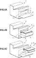
- Fig. 4A is a perspective view illustrating the apparatus body A in the state in which a door 13 is opened to attach or remove the cartridge B.
- Fig. 4B is a perspective view illustrating the apparatus body A and the cartridge B in the state in which the door 13 is opened to attach or remove the cartridge B and a cartridge tray 18 which is a movable member or pullout member is pulled out.
- Fig. 4C is a perspective view illustrating the cartridge B removed while the door 13 is opened and the cartridge tray 18 which is the movable member is pulled out.
- the cartridge tray 18 which is the movable member is movable into the apparatus body A with the cartridge B placed on the cartridge tray 18.
- the door 13 is rotatably attached to the apparatus body A, and when the door 13 is opened, there is a cartridge insertion opening 17.
- the cartridge tray 18 is disposed in the cartridge insertion opening 17.
- the cartridge tray 18 is the movable member for attaching the cartridge B to the apparatus body A.
- the cartridge tray 18 is pulled out to a predetermined position, the cartridge B is attachable to and removable from the cartridge tray 18 which is the movable member along an attachment/removal direction E.
- the cartridge B placed on the cartridge tray 18 is attached to the inside of (or inserted into) the apparatus body A in the direction of an arrow C in Fig. 4B along a guide rail (not illustrated).
- the apparatus body A includes a driving-side plate 15 and a non-driving-side plate 16 for supporting the cartridge B.
- the driving-side plate 15 includes a first driving-side support portion, a second driving-side support portion, and a rotation support portion 15c for supporting the rotation of the cartridge B.
- the non-driving-side plate 16 includes a first non-driving-side support portion 16a, a second non-driving-side support portion 16b, and a rotation support portion 16c.
- supported portions 73b and 73d of a drum bearing 73 and a driving-side boss 71a, a non-driving-side projecting portion 71f, and a non-driving-side boss 71g of the cleaning housing 71 are provided as supported portions of the cartridge B. Further, the supported portion 73b is supported by a first driving-side support portion 1a, and the supported portion 73d is supported by a second driving-side support portion 1b, and the driving-side boss 71a is supported by the rotation support portion 15c.
- non-driving-side projecting portion 71f is supported by the first non-driving-side support portion 16a and the second non-driving-side support portion 16b, and the non-driving-side boss 71g is supported by the rotation support portion 16c.
- a regulated portion provided on the drum bearing 73 is fitted to a regulating portion 2 provided on the apparatus body A so that the position of the cartridge B in the direction of a drum axis line is determined to position the cartridge B in the apparatus body A.
- Fig. 3 is a cross sectional view illustrating the cartridge B.
- Figs. 7A, 7B , 8A, and 8B are perspective views illustrating the structure of the cartridge B.
- Figs. 7B and 8B are partially-enlarged views illustrating dotted-line regions in Figs. 7A and 8A which are enlarged and viewed from a different angle. Description of screws used to join parts is omitted in the present exemplary embodiment.
- the cartridge B includes the cleaning unit 60 and the development unit 20. While the process cartridge in which the cleaning unit 60 and the development unit 20 are combined is attachable to (or insertable into) and removable from the image forming apparatus is described in the present exemplary embodiment, the structure is not limited to the above-described structure, and the cleaning unit 60 and the development unit 20 as independent units can separately be attachable to (or insertable into) and removable from the image forming apparatus. Further, while the cartridge B supported on the movable tray is moved to be inserted into the apparatus according to the present exemplary embodiment, the cartridge B can be inserted directly by a user.
- the cleaning unit 60 includes the drum 62, the charging roller 66, the cleaning member 77, the cleaning housing 71, and a cover member 72 fixed to the cleaning housing 71 by welding, etc.
- the cleaning housing 71 supports the drum 62, the charging roller 66, and the cleaning member 77.
- the charging roller 66 and the cleaning member 77 are each disposed to be in contact with the outer peripheral surface of the drum 62.
- the cleaning member 77 includes a rubber blade 77a and a support member 77b which supports the rubber blade 77a.
- the rubber blade 77a is a blade-shaped elastic member made of rubber which is an elastic material.
- the rubber blade 77a abuts on the drum 62 in the opposite direction to the direction in which the drum 62 is rotated.
- the rubber blade 77a abuts on the drum 62 in such a way that a leading edge portion of the rubber blade 77a faces upstream in the direction in which the drum 62 is rotated.
- the cleaning member is described with reference to the cleaning blade in the present exemplary embodiment, the cleaning member is not limited to the cleaning blade and can be a roller-shaped cleaning member, etc.
- Fig. 6A is a cross sectional view illustrating the cleaning unit 60.
- the waste developer hereinafter, referred to as "waste toner”
- the waste toner conveyance member 86 includes at least a shaft and a conveyance portion which conveys the toner.
- the cleaning unit 60 includes a first screw 86, a second screw 87, a third screw 88, the cleaning housing 71, a screw cover 74, and the cover member 72.
- a waste toner storage container 75 which is the developer storage container includes the cleaning housing 71, the screw cover 74, and the cover member 72 which are integrated, and the waste toner is stored in the waste toner storage container 75.
- the toner is conveyed in the direction of an arrow X by the first screw 86 which is a first waste toner conveyance member. Then, the toner is conveyed in the direction of an arrow Y by the second screw 87 which is a second waste toner conveyance member. Thereafter, the toner is accumulated in the waste toner chamber 71b by the third screw 88 which is a third waste toner conveyance member provided in the waste toner chamber 71b formed by the cleaning housing 71 and the cover member 72.
- the rotation axis lines of the first screw 86 and the third screw 88 are parallel to the rotation axis line of the drum 62, and the rotation axis line of the second screw 87 is orthogonal to the rotation axis line of the drum 62.
- the arrangement relationship is not limited to the above-described arrangement relationship and may be any arrangement relationship by which a driving force can be transmitted and the toner can be conveyed.
- the axis lines of the first screw 86 and the second screw 87 may be arranged to intersect with each other, and the rotation axis line of the second screw 87 may be arranged to incline inward from an end portion of the cartridge B in the lengthwise direction.
- the axis lines of the first screw 86 and the third screw 88 may be arranged not to be parallel but to intersect with each other.
- the screws that are the waste toner conveyance members are provided with a developer conveyance portion configured to convey the toner.
- the developer conveyance portion may have any structure by which the waste toner is conveyable, and a spiral-shaped protruding portion or a plurality of portions in a twisted-blade shape may be used.
- the waste toner conveyance members are not limited to the screws and may have any structure by which the waste toner is conveyable in the axial direction of the waste toner conveyance members.
- the waste toner may be conveyed with a coil, etc.
- a drum abutment sheet 65 for preventing a leakage of the waste toner from the cleaning housing 71 is provided on an edge portion of the cleaning housing 71 to abut on the drum 62.
- the drum 62 receives a driving force from a main body driving motor (not illustrated) which is a driving source so that the drum 62 is driven and rotated in the direction of an arrow R in Fig. 3 according to an image forming operation.
- the charging roller 66 is rotatably attached to each end portion of the cleaning unit 60 in the lengthwise direction (substantially parallel to the direction of the rotation axis line of the drum 62) of the cleaning housing 71 via a charging roller bearing 67.
- the charging roller bearing 67 is pressed toward the drum 62 by a biasing member 68 to press the charging roller 66 against the drum 62.
- the charging roller 66 is driven and rotated by the rotation of the drum 62.
- the development unit 20 includes the development roller 32, a developer container 23, and the development blade 42.
- the developer container 23 supports the development roller 32.
- the development roller 32 is disposed in such a way that the central axis of the development roller 32 is in the same direction as the direction of the rotation axis line of the drum 62.
- the magnet roller 34 is provided in the development roller 32.
- the development blade 42 for regulating a toner layer on the development roller 32 is disposed in the development unit 20.
- a space holding member 38 is attached to each end portion of the development roller 32, and the space holding members 38 abut on the drum 62 to hold the development roller 32 with a small space between the development roller 32 and the drum 62.
- a development roller abutment sheet 33 for preventing a leakage of the toner from the development unit 20 is provided on an edge portion of a bottom member 22 to abut on the development roller 32.
- the developer storage container includes a housing and the toner chamber 29 provided inside.
- the housing includes the developer container 23, which is a first housing, and the bottom member 22, which is a second housing.
- the toner chamber 29 is provided with the first conveyance member 43, the second conveyance member 44, and the third conveyance member 50.
- the first conveyance member 43, the second conveyance member 44, and the third conveyance member 50 agitate the toner T stored in the toner chamber 29 and conveys the toner T to the toner supply chamber 28.
- An opening 29a (portion specified by a broken line) is formed between the toner chamber 29 and the toner supply chamber 28.
- the opening 29a is sealed with a sealing member 45 until the cartridge B is used.
- the sealing member 45 is a sheet-shaped member made of a material such as polyethylene.
- One end side of the sealing member 45 is welded to the developer container 23, which is the housing, around the opening 29a, and the other end side of the sealing member 45 is fixed to the first conveyance member 43.
- the cleaning unit 60 and the development unit 20 are combined to form the cartridge B.
- the cleaning unit 60 includes the cleaning housing 71, the cover member 72, the drum 62, the drum bearing 73, which rotatably supports the drum 62, and a drum shaft 78.
- a driving-side drum flange 63 of the drum 62 that is provided on the driving-side is rotatably supported by a hole portion 73a of the drum bearing 73.
- the drum shaft 78 which is pressed into a hole portion 71c of the cleaning housing 71 rotatably supports a hole portion (not illustrated) of a non-driving-side drum flange 64.
- the development unit 20 includes the bottom member 22, which is the housing, the developer container 23, which is another housing, and a driving-side development side member 26, which is a part of the housings. Further, the development unit 20 includes the development blade 42, which is a developer layer thickness regulating member, and the development roller 32, which is the developer carrying member. Further, the development roller 32 is rotatably attached to the developer container 23 by a bearing member 27 provided on the driving-side and a bearing member 37 provided on the non-driving-side.
- the cleaning unit 60 and the development unit 20 are rotatably combined by a combining pin 69 to form the cartridge B.
- a first development support hole 23a and a second development support hole 23b are formed in the developer container 23 at the respective end portions of the development unit 20 in the lengthwise direction. Further, a first hanging hole 71i and a second hanging hole 71j are formed in the cleaning housing 71 at the respective end portions of the cleaning unit 60 in the lengthwise direction.
- the combining pin 69 that is pressed into the first hanging hole 71i and the second hanging hole 71j is fitted into the first development support hole 23a and the second development support hole 23b to rotatably connect the cleaning unit 60 and the development unit 20.
- a first hole portion 46Ra of a driving-side biasing member 46R is put around a boss 73c of the drum bearing 73, and a second hole portion 46Rb is put around a boss 26a of the driving-side development side member 26.
- a first hole portion 46Fa of a non-driving-side biasing member 46F is put around a boss 71k of the cleaning housing 71, and a second hole portion 46Fb is put around a boss 37a of the bearing member 37.
- the driving-side biasing member 46R and the non-driving-side biasing member 46F are formed of an extension spring.
- the development unit 20 is biased toward the cleaning unit 60 by a biasing force of the extension springs to ensure that the development roller 32 is pressed against the drum 62.
- the space holding members 38 provided on the respective end portions of the development roller 32 hold the development roller 32 with a predetermined space between the development roller 32 and the drum 62.
- Fig. 1 is a cross sectional view illustrating the development unit 20 to illustrate the remaining developer amount detection unit.
- Fig. 9A is a cross sectional view illustrating the development unit 20 cut along a line G-G in Fig. 6A .
- Fig. 9B is a cross sectional view illustrating the vicinity of the non-driving-side end portion of the development unit 20 cut along a line K-K in Fig. 9A .
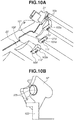
- FIG. 10A is a perspective view illustrating the remaining developer amount detection unit of the apparatus body A in addition to the cartridge B inserted in the apparatus body A when the development unit 20 is viewed from a direction N in Fig. 5B .
- Fig. 10B is a perspective view illustrating the bearing member 37 of the development roller 32 which is a part of the housing.
- Figs. 11A and 11B are side views illustrating a structure relating to an electrical connection of the development unit 20 and the remaining developer amount detection unit of the apparatus body A when the cartridge B is inserted into the apparatus body A.
- Fig. 12 illustrates a portion relating to the electrical connection of the remaining developer amount detection unit of the apparatus body A.
- the bottom member 22 which is the housing is provided with a conductive member and a contact point connected to the conductive member.
- the conductive member is a detection unit configured to detect the amount of toner which is the amount of developer stored in the housing.
- the housing is provided with two electrode plates, namely, the first electrode plate 91 as a first conductive member and the second electrode plate 92 as a second conductive member.
- Each of the first and second conductive members extends in the lengthwise direction of the development roller 32.
- the first electrode plate 91 is located closer to the development roller 32, which is the development sleeve, than the second electrode plate 92 is to the development roller 32. Further, as illustrated in Fig.
- a first electrode contact point plate 101 which is a first contact point
- a second electrode contact point plate 102 which is a second contact point
- a development contact point plate which is a development contact point
- the first electrode plate 91 is provided on one surface side of the bottom member 22 which is the housing
- the first electrode contact point plate 101 is provided on the other surface side on the opposite side.
- the same relationship applies to the second electrode plate 92 and the second electrode contact point plate 102 according to the present exemplary embodiment.
- the first electrode contact point plate 101, the second electrode contact point plate 102, and the development contact point plate 103 provided on the surface located on the outer side (or the surface located on the opposite side) with respect to the toner chamber 29 of the bottom member 22 are specified by dotted lines.
- the development contact point plate 103, which is the development contact point, the first electrode contact point plate 101, which is the first contact point, and the second electrode contact point plate 102, which is the second contact point, are disposed in this order from outside to inside in a perpendicular direction with respect to an insertion direction in which the cartridge B is inserted into the image forming apparatus.
- the development roller 32 includes a sleeve 32a which is a conductive member.
- the bearing member 37 which is a part of the housing is provided with a bearing member conductive resin portion 37b which is a conductive slide portion formed by molding two-color conductive resins. A part of the bearing member conductive resin portion 37b rotatably holds the development roller 32 and rubs the sleeve 32a of the development roller 32.
- the first electrode plate 91 and the second electrode plate 92 are disposed in such a way that a first surface 91a and a second surface 92a face the bottom member 22 which is the housing.
- the second surface 92a facing the first surface 91a according to the present exemplary embodiment is disposed on the inner surface of the toner chamber 29 to be in contact with the toner which is the developer.
- a protection film may cover the first surface 91a and the second surface 92a facing the first surface 91a.
- the first surface 91a and the second surface 92a each extend in the lengthwise direction of the developer carrying member.
- FIG. 9B illustrates the structure of a cross section of the first electrode plate 91 and the bottom member 22.
- the first electrode plate 91 passes through a hole portion 22a of the bottom member 22 in a non-driving-side end portion of the first surface 91a and is exposed to the outside of the toner chamber 29.
- a first exposed portion 91d is the portion of the first electrode plate 91 that is exposed to the outside of the toner chamber 29.
- the first electrode plate 91 is connected at the first exposed portion 91d to the first electrode contact point plate 101 which is the first contact point.
- the exposed portion may directly be a contact point that is electrically connected to the contact point on the image forming apparatus side.
- the first electrode contact point plate 101 is stacked on the first exposed portion 91d. While the structure of the first electrode plate 91 is illustrated in Fig. 9B , the above-described structure also applies to the second electrode plate 92, and the second electrode plate 92 includes a second exposed portion 92d corresponding to the first exposed portion 91d (see Fig. 10A ). Further, the second exposed portion 92d is connected to the second electrode contact point plate 102 which is the second contact point.
- the second electrode contact point plate 102 is similarly stacked on the second exposed portion 92d to cover the second exposed portion 92d. Further, as illustrated in Fig. 10B , the bearing member conductive resin portion 37b of the bearing member 37 rotatably supports the sleeve 32a of the development roller 32 to be electrically connected to the sleeve 32a of the development roller 32. Further, the development contact point plate 103 is connected to the bearing member conductive resin portion 37b.
- the non-driving-side end portion of the first surface 91a extends to the first electrode contact point plate 101 in the lengthwise direction of the developer carrying member.
- a non-driving-side end portion of the second surface 92a extends to the second electrode contact point plate 102 in the lengthwise direction of the developer carrying member.
- the first exposed portion 91d and the second exposed portion 92d are provided on the non-driving-side end portions of the electrode plates 91 and 92 according to the present exemplary embodiment.
- the first exposed portion 91d and the second exposed portion 92d may be provided on the end portions so that the shapes of the vicinities of the first exposed portion 91d and the second exposed portion 92d can be simplified by reducing the number of bends, etc. Furthermore, no electrode plate may be provided on the non-driving side of the electrode contact point plates 101 and 102 so that costs such as material costs can be reduced.
- the apparatus body A includes a first pressing portion 111, a second pressing portion 112, and a development pressing portion 113 which are main body contact points electrically connectable to the contact points of the cartridge B.
- the first pressing portion 111, the second pressing portion 112, and the development pressing portion 113 are a first main body contact point, a second main body contact point, and a development main body contact point, respectively, and are electrically connectable to the contact points of the cartridge B.
- the first pressing portion 111, the second pressing portion 112, and the development pressing portion 113 each include a twisted coil spring and are disposed rotatably within a predetermined angle range around the center of the twisted coil spring.
- first electrode contact point plate, the second electrode contact point plate, and the development contact point plate respectively correspond to a first pressed portion, a second pressed portion, and a development pressed portion (101a, 102a, 103a).
- the first pressed portion, the second pressed portion, and the development pressed portion respectively abut on the first pressing portion, the second pressing portion, and the development pressing portion (111, 112, 113) of the apparatus body A to be electrically connected.
- the first pressed portion 101a, the second pressed portion 102a, and the development pressed portion 103a are all disposed to face downward in the vertical direction.
- the first electrode contact point plate 101 and the second electrode contact point plate 102 are disposed at different positions in the lengthwise direction of the developer carrying member or the perpendicular direction with respect to the insertion direction in which the development device is inserted into the image forming apparatus.
- the first and second pressing portions 111 and 112 are disposed not to overlap in a perpendicular direction M (according to the present exemplary embodiment, the perpendicular direction M is the same direction as the lengthwise direction of the developer carrying member) which is perpendicular to the insertion direction when the cartridge B is inserted into the apparatus body A.
- the development contact point plate 103 which is the development contact point
- the first electrode contact point plate 101 which is the first contact point
- the second electrode contact point plate 102 which is the second contact point
- the first contact point is disposed on a more inner side than the development contact point in the perpendicular direction with respect to the insertion direction in which the cartridge B is inserted into the image forming apparatus.
- the second contact point is disposed on a more inner side than the first contact point in the perpendicular direction with respect to the insertion direction in which the cartridge B is inserted into the image forming apparatus.
- the first contact point is disposed between the second contact point and the development contact point.
- the first contact point is disposed between the center of the cartridge B in the lengthwise direction and the development contact point.
- the second contact point is disposed between the center of the cartridge B in the lengthwise direction and the first contact point.
- the second contact point is disposed between the center of the cartridge B in the lengthwise direction and the development contact point.
- the first contact point, the second contact point, and the development contact point are disposed at predetermined intervals (predetermined distances) not to overlap in an orthogonal direction (which is the same direction as the insertion direction in which the cartridge B placed on the cartridge tray 18 is inserted) with respect to the lengthwise direction. Accordingly, when the cartridge B is inserted into the image forming apparatus, the first main body contact point of the apparatus body A does not come into contact with the second electrode contact point plate 102 which is the second contact point of the cartridge B.
- the development contact point is disposed upstream with respect to the first contact point and the second contact point is disposed downstream with respect to the first contact point.
- the positional relationship of the contact points is described based on the positions of the outside end portions of the contact points in the perpendicular direction M. Alternatively, the positional relationship may be considered based on the abutment positions of the main body contact points.
- FIG. 11A illustrates a state before the cartridge B is completely attached to the apparatus body A and immediately before the first electrode contact point plate 101, the second electrode contact point plate 102, and the development contact point plate 103 respectively come into contact with the first pressing portion 111, the second pressing portion 112, and the development pressing portion 113.
- Fig. 11B illustrates the state in which the cartridge B is completely attached to the apparatus body A, and at this time the position of the cartridge B is determined.
- the first pressing portion 111, the second pressing portion 112, and the development pressing portion 113 respectively press the first pressed portion 101a, the second pressed portion 102a, and the development pressed portion 103a due to the resilience of the respective twisted coil springs.
- first electrode contact point plate 101 and the second electrode contact point plate 102 are disposed to overlap on the straight line of the insertion direction of the cartridge B.
- This arrangement can also be described as an arrangement in which the first electrode contact point plate 101 and the second electrode contact point plate 102 are disposed in corresponding positions in the perpendicular direction M (or the lengthwise direction of the developer carrying member).
- This arrangement is different from the arrangement illustrated in Fig. 12 .
- the first pressing portion 111 and the second pressing portion 112 are both disposed to overlap in the insertion direction (orthogonal direction to the lengthwise direction of the cartridge B) of the cartridge B.
- the first electrode contact point plate 101 when the cartridge B is attached in the direction of the arrow C, the first electrode contact point plate 101 is moved onto the second pressing portion 112, moved further while rubbing, and then inserted to cancel the contact. Similarly, when the cartridge B is removed in the opposite direction to the direction of the arrow C, the first electrode contact point plate 101 is moved onto and over the second pressing portion 112. In this arrangement, the movement generates a load during the attachment or removal of the cartridge B, so the cartridge B is less likely to be attached to or removed from the apparatus body A smoothly.
- the development contact point plate 103, the first electrode contact point plate 101, and the second electrode contact point plate 102 are staggered in the perpendicular direction M. Further, similarly, the development pressing portion 113, the first pressing portion 111, and the second pressing portion 112 are staggered in the perpendicular direction M. In this way, when the cartridge B is moved in the direction of the arrow C, the first electrode contact point plate 101 is not likely to be moved onto the second pressing portion 112. Similarly, the development contact point plate 103 is not likely to come into contact with the first pressing portion 111 and the second pressing portion 112 and is, therefore, not likely to be moved onto the first pressing portion 111 and the second pressing portion 112. For this reason, the path along which the cartridge B is moved in the direction of the arrow C can be simplified to reduce the size of the apparatus body A.
- the contact points are provided on not the side surface but the bottom surface of the toner chamber 29. This makes it unnecessary to provide an additional member to extend the contact points to the position of the side surface of the cartridge B in the lengthwise direction, so the structure can be simplified. According to the present exemplary embodiment, the contact points are exposed on the bottom surface.
- a development bias power supply 130 which is a voltage application unit applies an alternating current (AC) voltage to the development roller 32
- a current corresponding to the electrostatic capacitance between the development roller 32 and the first surface 91a is induced between the development roller 32 and the first surface 91a.
- the development bias power supply 130 which is the voltage application unit applies an AC voltage to the second electrode plate 92
- a current corresponding to the electrostatic capacitance between the first surface 91a and the second surface 92a facing the first surface 91a is induced.
- the electrostatic capacitance between the development roller 32 and the first surface 91a changes according to the amount of toner which is the amount of developer between the development roller 32 and the first surface 91a.
- the electrostatic capacitance between the first surface 91a and the second surface 92a changes according to the amount of toner which is the amount of developer between the first surface 91a and the second surface 92a.
- the value of current passing through the first electrode plate 91 is converted into a voltage value via the first electrode contact point plate 101 and measured by a developer amount detection device 131 which is the detection unit in the apparatus body A.
- the current may be detected directly.
- the following describes a change in the state of the toner in the development unit 20 throughout the lifetime of the cartridge B.
- the inside of the development unit 20 is substantially filled with the toner which is the developer.
- the overall amount of toner in the development unit 20 decreases.
- the toner is conveyed toward the development roller 32 by the first, second, and third conveyance members (43, 44, 50) in the development unit 20, so the amount of toner is larger at smaller distances from the development roller 32.
- the amount of toner which is the amount of developer in the entire cartridge B (or housing) is decreased, an amount by which the amount of toner in a region near the development roller 32 (e.g., region from the development roller 32 to the first conveyance member 43) is decreased is small. Therefore, the amount of toner is larger in the region near the development roller 32 than in other regions.
- the accuracy of the detection of the amount of remaining developer between the development roller 32 and the first surface 91a needs to be higher than that between the first surface 91a and second surface 92b. High detection accuracy is required especially in the case of a cartridge capable of storing a large amount of developer in the cartridge (or housing).
- the second electrode contact point plate 102 is disposed in a region I between the first electrode contact point plate 101 and a lengthwise center C of the development roller 32 in the perpendicular direction M with respect to the insertion direction of the cartridge B or the lengthwise direction of the developer carrying member. Specifically, the second electrode contact point plate 102 is disposed between the first electrode contact point plate 101 and the center of the development roller 32 in the lengthwise direction.
- the first contact point is disposed on a more inner side than the development contact point in the perpendicular direction with respect to the insertion direction in which the cartridge B is inserted into the image forming apparatus.
- the second contact point is disposed on a more inner side than the first contact point in the perpendicular direction with respect to the insertion direction in which the development device is inserted into the image forming apparatus.
- the above-described arrangement allows the conductive members to be provided up to the vicinity of the end portion of the bottom member 22, which is the housing, in the lengthwise direction of the development roller 32. For this reason, the width of the first surface 91a in the lengthwise direction which requires accurate detection of the amount of remaining developer due to the small distance from the development roller 32 can be set larger than the width in the lengthwise direction of the second surface 92a. This enables accurate detection of the amount of remaining toner in the vicinity of the development roller 32.
- the first exposed portion 91d and the second exposed portion 92d are provided at the bottom portion of the bottom member 22 so that the contact points do not need to be provided at the side surface of the cartridge B. This makes it unnecessary to extend the electrode plates to the vicinity of a side wall on the non-driving-side, so costs can be reduced. Further, the width of the first electrode plate 91 located closer to the development roller 32 than the second electrode plate 92 is to the development roller 32 is kept long to enable accurate detection of the amount of remaining developer in the vicinity of the development roller 32.
- an electrode sheet is used in place of the electrode plate 91. Being a sheet, the electrode sheet alone is flexible.
- the electrode sheet to which conductivity is imparted is used as a conductive resin member. While the conductive resin member in which a conductive material such as carbon black is dispersed in a resin is used in the present exemplary embodiment, the conductive resin member is not limited to the above-described conductive resin member, and any material of a resin having conductivity may be used.
- a first electrode sheet 96 is provided in place of the first electrode plate 91, and a second electrode sheet 97 is provided in place of the second electrode plate 92.
- the first electrode sheet 96 and second electrode sheet 92 are conductive resin sheets.
- the first electrode sheet 96 includes a first surface 96a corresponding to the first surface 91a of the first electrode plate 91, and the second electrode sheet 97 includes a second surface 97a corresponding to the second surface 92a of the second electrode plate 92.
- the arrangement of the electrode sheets is similar to the arrangement according to the first exemplary embodiment.
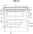
- a third electrode sheet 98 and a fourth electrode sheet 99 are further provided.
- the third electrode sheet 98, which is a third conductive member, and the fourth electrode sheet 99, which is a fourth conductive member, are provided so that even the amount of developer in the farthest storage unit from the development roller 32 is detectable in order to successively detect the amount of developer in the cartridge B.
- a third electrode contact point plate 98a is provided on the back surface of the bottom member 22, which is the housing, on an end portion side of the third electrode sheet 98 in the lengthwise direction of the cartridge.
- a fourth electrode contact point plate 99a is provided on the back surface of the bottom member 22, which is the housing, on an end portion side of the fourth electrode sheet 99 in the lengthwise direction of the cartridge. While four electrode sheets are used in the second exemplary embodiment, three electrode sheets may be used.
- FIGS. 14A, 14B , 15A, and 15B are perspective views illustrating a developer storage container to illustrate the method of manufacturing a developer storage container.
- FIGs. 15A and 15B are cross sectional views illustrating molds to illustrate the method of manufacturing a developer storage container.
- the developer storage container includes the developer container 23 and the bottom member 22 as described above.
- the first electrode sheet 96 and the second electrode sheet 97 are formed integrally with the bottom member 22.
- Figs. 15A and 15B illustrate an example of a cross sectional view of an entire mold for molding the bottom member 22.
- Fig. 15A illustrates a state in which the mold is opened
- Fig. 15B illustrates a state in which the mold is closed.
- a first mold 121 and a second mold 122 are provided, and a shape corresponding to the shape of the surface of the bottom member 22 is formed on each of the first mold 121 and the second mold 122.
- the first mold 121 is provided with an injection opening (gate) 123 through which a resin is injected into the mold.
- the first electrode sheet 96 and the second electrode sheet 97 respectively include a first suctioned portion 96b and a second suctioned portion 97b.
- the third electrode sheet 98 and the fourth electrode sheet 99 respectively include a third suctioned portion 98b and a fourth suctioned portion 99b.
- Fine air holes are formed in the surface of the second mold 122 that corresponds to the first suctioned portion 96b to the fourth suctioned portion 99b.
- the air holes are connected to a suction device (not illustrated) to suction air through the air holes so that the first electrode sheet 96 to the fourth electrode sheet 99 are adsorbed and fixed onto the second mold 122.
- the first mold 121 and the second mold 122 are put together (closed).
- a molten resin is injected through the injection opening 123 into a void portion (cavity) 124 formed when the first mold 121 and the second mold 122 are put together.
- the molten resin is cured while being pressed against the first electrode sheet 96 to the fourth electrode sheet 99 so that the bottom member 22 is molded integrally with the first electrode sheet 96 to the fourth electrode sheet 99.
- the resin in the void portion 124 flows from the injection opening 123 toward an end portion of the shape to be molded.
- the injection opening 123 can be defined as upstream, whereas the end portion of the shape to be molded can be defined as downstream.
- the resin injected from the injection opening 123 flows in the direction of an arrow J from upstream toward downstream to mold the shape of the bottom member 22.
- Figs. 16A, 16B, 16C , 17A, and 17B illustrate a possible problem that can occur when a fixing position is changed while the first electrode sheet 96 is fixed to the second mold 122.
- Figs. 17A and 17B are cross sectional views illustrating the first mold 121, the second mold 122, and the first electrode sheet 96 to illustrate a structure at the time of molding the bottom member 22 near a slide plug 125 of the second mold 122.
- the first suctioned portion 96b of the first electrode sheet 96 which is provided at an upstream end portion of the first electrode sheet 96 is adsorbed and fixed onto the second mold 122 by the fine air holes (not illustrated) formed in the surface of the second mold 122.
- the first suctioned portion 96b has the role of fixing the relative position to the mold in the direction of the arrow J of the resin when the resin flows in the direction of the arrow J.
- the first suctioned portion 96b is disposed on the downstream side of the upstream end portion of the first electrode sheet 96 as illustrated in Fig. 16B.
- the first suctioned portion 96b may be pressed by the molten resin flowing from upstream in the direction of the arrow J.
- the upstream end portion of the first electrode sheet 96 which is located on the upstream side of the first suctioned portion 96b in the direction of the arrow J may be separated from the second mold 122.
- the molten resin may flow between the first electrode sheet 96 and the second mold 122 in a region Z1 which is a portion of the first electrode sheet 96 that is on the upstream side of the first suctioned portion 96b.
- a part of the first surface 96a in the region Z1 may be unexposed to the toner supply chamber 28 and covered by the resin due to the molded bottom member 22.
- the covering resin may affect the electrostatic capacitance between the development roller 32 and the first surface 91a or the electrostatic capacitance between the first surface 91a and the second surface 92a to decrease the accuracy of the detection of the amount of remaining developer.
- the molten resin flowing from upstream along the direction of the arrow J may flow into a region Z2 formed between the first suctioned portions 96b. Then, the flowing molten resin may push the first electrode sheet 96 in the region Z2 to separate the first electrode sheet 96 in the region Z2 from the second mold 122.
- the molten resin may flow between the first electrode sheet 96 and the second mold 122 in the region Z2, and a part of the first surface 96a in the region Z2 may be unexposed to the toner supply chamber 28 and covered by the resin at the molded bottom member 22. Consequently, the covering resin may affect the electrostatic capacitance between the development roller 32 and the first surface 91a or the electrostatic capacitance between the first surface 91a and the second surface 92a to decrease the accuracy of the detection of the amount of remaining developer.
- the suctioned portions of the electrode sheets are disposed upstream of the flow of the resin to accurately arrange the electrode sheets at designed positions on the housing.
- the first suctioned portion 96b is desirably disposed on the upstream end portion as illustrated in Fig. 16A .
- the second to fourth electrode sheets (97 to 99) include second to fourth exposed portions (97d, 98d, 99d) corresponding to the first exposed portion 96d.
- the second mold 122 includes the slide plug 125.
- the slide plug 125 is movable between an entry position and an exit position in a direction from the second mold 122 toward the first mold 121.
- Fig. 17A illustrates the slide plug 125 at the entry position
- Fig. 17B illustrates the slide plug 125 at the exit position.
- the slide plug 125 is moved to the entry position in Fig. 17A .
- the first electrode sheet 96 is sandwiched between the slide plug 125 and the first mold 121.
- the molten resin is injected from the injection opening 123 into the void portion 124.
- the slide plug 125 is moved to the exit position in Fig. 17B (in the direction of an arrow K). Then, the molten resin flows into a region F formed as a result of the movement of the slide plug 125 from the entry position to the exit position. In this way of molding, the first electrode sheet 96 and the second electrode sheet 97 are inserted and molded in the bottom member 22.
- the developer storage container manufactured by the above-described manufacturing method has a structure in which the non-driving-side end portion of the first surface 96a of the first electrode sheet 96 comes into the bottom member 22 and the first exposed portion 96d is exposed to the outside of the toner chamber 29.
- the first electrode sheet 96 includes a detection unit having the first surface 96a, a relay unit formed through the inside of the housing and connected to the first exposed portion 96d, and the first exposed portion 96d. Not only the first electrode sheet 96 but also the second to fourth electrode sheets 97 to 99 have the above-described structure. Specifically, the electrode sheets are disposed on the housing and include the detection unit, the relay unit, and the exposed portion.
- the first electrode sheet 96 is connected to the first electrode contact point plate 101 at the first exposed portion 96d.
- a resin sheet having a thickness of 0.1 mm is used.
- conductive refers to a surface resistivity of 10 kQ/sq or lower as measured by a measurement method stipulated in JIS K 7194, and the term “not conductive” refers to a surface resistivity that is higher than 10 kQ/sq.
- EVA ethylene-vinyl acetate copolymer
- the EVA resin is bonded to a polystyrene (PS) resin with the heat and pressure applied during the molding of the bottom member 22 using the above-described molding method to integrally form the electrode sheets, which are conductive resin sheets, and the bottom member 22.
- PS polystyrene
- the thickness of the resin sheet may be selected as appropriate.
- the EVA resin which is adhesive to the material of the bottom member 22 is selected as a material of the resin sheet, a resin having compatibility to melt with the resin of the bottom member 22 to be combined without an interface can be used as a material of the resin sheet.
- the resin used in the bottom member 22 has a heat distortion temperature of about 90 degrees Celsius
- the ethylene-vinyl acetate copolymer (EVA) resin used in the remaining developer amount detection member which is the conductive resin sheet has a heat distortion temperature of about 80 degrees Celsius.
- the above-specified heat distortion temperatures of the bottom member 22 and the electrode sheets are mere examples, and the heat distortion temperatures are not limited to those specified above as long as the heat distortion temperature of the resin to be used to form the electrode sheets is lower than the heat distortion temperature of the resin to be used to form the housing.
- the electrode sheets are inserted into the developer storage container and molded as described above.
- the development contact point plate 103, the first electrode contact point plate 101, the second electrode contact point plate 102, the third electrode contact point plate 98a, and the fourth electrode contact point plate 99a are disposed in this order from outside toward the lengthwise center C in the lengthwise direction of the cartridge.
- the above arrangement is described based on the positions of outside end portions of the members such as the development contact point plate 103 in the lengthwise direction of the cartridge.
- the first electrode contact point plate 101 is disposed between the development contact point plate 103 and the second electrode contact point plate 102.
- the second electrode contact point plate 102 to the fourth electrode contact point plate 99a are disposed in the region I between the first electrode contact point plate 101 and the lengthwise center C of the development roller 32.
- the third electrode contact point plate 98a is disposed between the second electrode contact point plate 102 and the fourth electrode contact point plate 99a.
- the above-described arrangement is employed so that the width of the first surface 96a, which is located close to the development roller 32, in the lengthwise direction which requires accurate detection of the amount of remaining developer is set larger than the width of the second surface 97a in the lengthwise direction.
- the lengths of the first surface 96a, the second surface 97a, a third surface 98e of the third electrode sheet 98, and a fourth surface 99e of the fourth electrode sheet 99 in the lengthwise direction decrease in this order.
- the first surface 96a has the longest length in the lengthwise direction
- the fourth surface 99e has the shortest length.
- the contact points do not have to be disposed on the side surface of the cartridge, and the electrode sheets do not have to be extended to the side surface, so costs are reduced. Further, the width of the first electrode sheet located at the smallest distance from the development roller which is the developer carrying member can be set larger to enable accurate detection of the amount of remaining developer.
- Fig. 18 is a cross sectional view illustrating the development unit 20 to illustrate the remaining developer amount detection unit.
- Fig. 19 is a perspective view illustrating the remaining developer amount detection unit of the apparatus body A in addition to the cartridge B inserted in the apparatus body A when the development unit 20 is viewed from the direction N in Fig. 5B .
- the bearing member conductive resin portion 37b is provided as a contact point.
- the bearing member conductive resin portion 37b has a development pressed surface 103b which is perpendicular to the shaft of the development roller 32. Further, the development pressing portion 113 of the apparatus body A is horizontal to the development contact point and projects toward the development contact point.
- the development pressing portion 113 presses the development pressed surface 103b due to the resilience of the twisted coil spring.
- the above-described arrangement reduces the necessity to provide a system for pressing the development contact point plate 103 from below in the vertical direction on a lower portion of the development unit 20 and a corresponding position of the apparatus body A.
- This allows the first electrode contact point plate 101 and the second electrode contact point plate 102 to be disposed at farther positions on the non-driving side from the center as illustrated in Fig. 18 than those in the first exemplary embodiment.
- the electrode sheet is extendable up to the edge in the developer storage container, and the distance from the lengthwise center C of the development roller to the non-driving-side end portion of the electrode sheet can be increased. This makes it possible to extend the width of the first electrode plate 96 in the lengthwise direction to further improve the remaining amount detection accuracy.
- the bearing member conductive resin portion 37b is provided on the bearing member 37, it is less necessary to add another member to the side surface. This makes it possible to improve the remaining amount detection accuracy while preventing an increase in size of the apparatus body A and the cartridge B.
Landscapes
- Physics & Mathematics (AREA)
- General Physics & Mathematics (AREA)
- Engineering & Computer Science (AREA)
- Computer Vision & Pattern Recognition (AREA)
- Electrophotography Configuration And Component (AREA)
Abstract
Description
- The present invention relates to a development device, a process cartridge, and an image forming apparatus.
- In the description, the term "image forming apparatus" refers to an apparatus which forms images on recording materials. The term "process cartridge" refers to a process cartridge including at least an image carrying member. In many cases, a process cartridge is a cartridge in which a charging unit, a development unit, a cleaning unit, and an image carrying member are integrated and which is attachable to (or insertable into) and removable from the main body of an image forming apparatus. Further, the term "development device" refers to a development device including at least a developer carrying member. In many cases, a development device is a development device in which a developer carrying member and a development frame for supporting the developer carrying member are integrated and which is attachable to (or insertable into) and removable from the main body of an image forming apparatus.
- Examples of an electrophotographic image forming apparatus include copying machines, light-emitting diode (LED) printers, laser printers, and facsimile apparatuses.
- In an electrophotographic image forming apparatus (hereinafter, referred to simply as "image forming apparatus"), an electrophotographic photosensitive member, i.e., photosensitive drum, which is an image carrying member and is in general in the shape of a drum, is uniformly charged. Next, the charged photosensitive drum is selectively exposed to form an electrostatic latent image (electrostatic image) on the photosensitive drum. Next, the electrostatic latent image formed on the photosensitive drum is developed with a toner, which is developer, to form a toner image. Then, the toner image formed on the photosensitive drum is transferred onto a recording material such as a recording sheet or plastic sheet, and the toner image transferred on the recording material is heated and pressed so that the toner image is fixed to the recording material. In this way, an image is recorded.
- In general, such an image forming apparatus requires resupply of toner and maintenance of various processing units. To facilitate the toner resupply and maintenance, a process cartridge in which a photosensitive drum, a charging unit, a development unit, a cleaning unit, etc. are integrated in a frame member and which is attachable to and removable from the main body of an image forming apparatus has been put into practical use.
- This process cartridge method enables users to conduct maintenance of an apparatus on their own, so operability is improved significantly, and an image forming apparatus with excellent usability is provided. For this reason, the process cartridge method is widely used in image forming apparatuses.
- In such a process cartridge, in some cases, the amount of toner needs to be detected. Japanese Patent Application Laid-Open No.
2015-34984 - In a case of a cartridge capable of storing a large amount of toner which is developer, it is sometimes desirable to modify the configuration discussed in Japanese Patent Application Laid-Open No.
2015-34984 - However, in a case in which a plurality of contact points of the developer carrying member and the conductive members needs to be provided so as to ensure electrical connections from an image forming apparatus, the contact points of the developer carrying member and the conductive members may come into contact with a contact point of the image forming apparatus that is not supposed to be connected, depending on the arrangement of the contact points. Thus, there are demands for stable connections of contact points.
- According to a first aspect of the present invention, there is provided a development device as specified in
claims 1 to 6. - According to a second aspect of the present invention, there is provided a process cartridge as specified in
claim 7. According to a third aspect of the present invention, there is provided an image forming apparatus specified inclaims 8 to 10. - Further features of the present invention will become apparent from the following description of exemplary embodiments with reference to the attached drawings.
-
-
Fig. 1 is a cross sectional view illustrating a development unit of a process cartridge according to a first exemplary embodiment. -
Fig. 2 is a cross sectional view illustrating a main body of an image forming apparatus and the process cartridge according to the first exemplary embodiment. -
Fig. 3 is a cross sectional view illustrating the process cartridge according to the first exemplary embodiment. -
Figs. 4A to 4C illustrate an operation of attaching/removing the process cartridge to/from the image forming apparatus. -
Figs. 5A and 5B are perspective views illustrating a driving-side positioning portion and a non-driving-side positioning portion of the main body of the image forming apparatus. -
Figs. 6A and 6B are cross sectional views illustrating the inside of a cleaning container of the process cartridge according to the first exemplary embodiment. -
Figs. 7A and 7B are exploded views illustrating the process cartridge according to the first exemplary embodiment. -
Figs. 8A and 8B are exploded views illustrating the process cartridge according to the first exemplary embodiment. -
Figs. 9A and 9B are cross sectional views illustrating the development unit of the process cartridge according to the first exemplary embodiment. -
Figs. 10A and 10B are a perspective view illustrating the development unit of the process cartridge and the main body of the image forming apparatus and a perspective view illustrating a bearing member of the process cartridge according to the first exemplary embodiment. -
Figs. 11A and 11B are side views illustrating the development unit of the process cartridge and the main body of the image forming apparatus according to the first exemplary embodiment. -
Fig. 12 is a cross sectional view illustrating the main body of the image forming apparatus according to the first exemplary embodiment. -
Fig. 13 is a cross sectional view illustrating a development unit of a process cartridge according to a second exemplary embodiment. -
Figs. 14A and 14B are perspective views illustrating a developer storage container of the process cartridge according to the second exemplary embodiment. -
Figs. 15A and 15B are cross sectional views illustrating molds for use in manufacturing the developer storage container of the process cartridge according to the second exemplary embodiment. -
Figs. 16A to 16C are front views illustrating the molds for use in manufacturing the developer storage container of the process cartridge and a conductive member of the process cartridge according to the second exemplary embodiment. -
Figs. 17A and 17B are cross sectional views illustrating the molds for use in manufacturing the developer storage container of the process cartridge and the conductive member of the process cartridge according to the second exemplary embodiment. -
Fig. 18 is a cross sectional view illustrating a development unit of a process cartridge according to a third exemplary embodiment. -
Fig. 19 is a perspective view illustrating the development unit of the process cartridge according to the third exemplary embodiment. - Various exemplary embodiments of the invention will be described in detail below with reference to the drawings. It should be noted, however, that sizes, materials, shapes, relative locations, etc. of components described in the exemplary embodiments are to be changed as appropriate according to the structure of an apparatus to which an exemplary embodiment of the present invention is applied and various conditions. In other words, the exemplary embodiments described below are not intended to limit the scope of the invention. Further, each of the embodiments of the present invention described below can be implemented solely or as a combination of a plurality of the embodiments or features thereof where necessary or where the combination of elements or features from individual embodiments in a single embodiment is beneficial.
- In the present description, the direction of a rotation axis line of an electrophotographic photosensitive drum which is an image carrying member is defined as a lengthwise direction.
- The direction of a rotation axis line of a developer carrying member is parallel to the direction of the rotation axis line of the image carrying member, so the direction of the rotation axis line of a development roller (or development sleeve) which is the developer carrying member is also defined as the lengthwise direction.
- Further, in the lengthwise direction, the side of the electrophotographic photosensitive drum that receives a driving force from the main body of an image forming apparatus is defined as a driving side, and the side opposite to the driving side is defined as a non-driving side.
- An entire structure of an image forming apparatus and an image forming process are described with reference to
Figs. 2 and3 . -
Fig. 2 is a cross sectional view illustrating the main body (hereinafter, referred to as "apparatus body A") of an electrophotographic image forming apparatus (hereinafter, referred to as "image forming apparatus") and a process cartridge (hereinafter, referred to as "cartridge B") according to a first exemplary embodiment of the present invention. -
Fig. 3 is a cross sectional view illustrating the cartridge B. - The apparatus body A corresponds to the electrophotographic image forming apparatus that does not include the cartridge B. While the cartridge B according to the present exemplary embodiment is a process cartridge, the cartridge B can be a development device. In a case in which the development device is independently attachable to (or insertable into) and removable from the apparatus body, the apparatus body A corresponds to the image forming apparatus that does not include the development device.
- The image forming apparatus illustrated in
Fig. 2 is an electrophotographic laser beam printer in which the cartridge B is attachable to (or insertable into) and removable from the apparatus body A. When the cartridge B is attached to the apparatus body A, an exposure device 3 (laser scanner unit) for forming a latent image on an electrophotographicphotosensitive drum 62 of the cartridge B is disposed. Further, a sheet tray 4 is disposed below the cartridge B. The sheet tray 4 stores recording materials (hereinafter, referred to as "sheet material P") on which images are to be formed. - Further, the apparatus body A includes a
pickup roller 5a, a pair ofsheet feeding rollers 5b, a pair ofsheet conveying rollers 5c, atransfer guide 6, atransfer roller 7, aconveyance guide 8, a fixingdevice 9, a pair ofsheet discharge rollers 10, asheet discharge tray 11, etc. disposed sequentially along a conveyance direction D in which the sheet material P is conveyed. The fixingdevice 9 includes aheating roller 9a and apressing roller 9b. - Next, an outline of the image forming process will be described below. Based on a print start signal, the electrophotographic photosensitive drum 62 (hereinafter, referred to as "
drum 62") is driven and rotated at a predetermined circumferential velocity (processing speed) in the direction of an arrow R. - A charging
roller 66 which is a charging member and to which a bias voltage is applied is brought into contact with the outer peripheral surface of thedrum 62 to uniformly and evenly charge the outer peripheral surface of thedrum 62. - The
exposure device 3 outputs laser light L corresponding to image information. The laser light L passes through alaser opening 71h in a cleaninghousing 71 of the cartridge B and scans and exposes the outer peripheral surface of thedrum 62. In this way, an electrostatic latent image corresponding to the image information is formed on the outer peripheral surface of thedrum 62. - Further, a
first conveyance member 43, asecond conveyance member 44, and athird conveyance member 50 are rotated to agitate toner T in atoner chamber 29 and convey the toner T to atoner supply chamber 28 in adevelopment unit 20 which is the development device, as illustrated inFig. 3 . Thefirst conveyance member 43, thesecond conveyance member 44, and thethird conveyance member 50 include a shaft portion and a sheet-shaped conveyance portion, and the sheet-shaped conveyance portion is attached to the shaft portion. As the shaft portion is rotated, the sheet-shaped conveyance portion is also rotated, and the toner T is pushed by the sheet and conveyed. The shaft portion of the closest one of thefirst conveyance member 43, thesecond conveyance member 44, and thethird conveyance member 50 to the development roller is located immediately above a position between first and second electrode plates when viewed from the lengthwise direction of the development roller. - The
first conveyance member 43, thesecond conveyance member 44, and thethird conveyance member 50 are disposed in order from the developer carrying member side. Thetoner chamber 29 and thetoner supply chamber 28 include a housing. According to the present exemplary embodiment, two housings, namely, first and second housings, are welded to form thetoner chamber 29 and thetoner supply chamber 28. - The toner T which is developer is borne on the surface of a
development roller 32, which is the developer carrying member, by a magnetic force of a magnet roller 34 (stationary magnet). - While the toner T is triboelectrically charged, the layer thickness of the toner T on the peripheral surface of the
development roller 32 is regulated by adevelopment blade 42 which is a developer layer regulation member. - The toner T is transferred onto the
drum 62 according to the electrostatic image or electrostatic latent image and visualized as a toner image which is a developer image. - Further, as illustrated in
Fig. 2 , the sheet material P stored in a lower portion of the apparatus body A is conveyed from the sheet tray 4 by thepickup roller 5a, the pair ofsheet feeding rollers 5b, and the pair ofsheet conveying rollers 5c in synchronization with the timing of output of the laser light L. Then, the sheet material P is conveyed through thetransfer guide 6 to a transfer position between thedrum 62 and thetransfer roller 7. At the transfer position, the toner image is sequentially transferred from thedrum 62 onto the sheet material P. - The sheet material P with the transferred toner image is separated from the
drum 62 and conveyed along theconveyance guide 8 to thefixing device 9. Then, the sheet material P is passed through a nip portion formed by theheating roller 9a and thepressing roller 9b of the fixingdevice 9. At the nip portion, fixing processing by pressing and heating is conducted to fix the toner image to the sheet material P. The sheet material P to which the toner image has been fixed is conveyed to the pair ofsheet discharge rollers 10 and discharged onto thesheet discharge tray 11. - Further, as illustrated in
Fig. 3 , after the toner image is transferred from thedrum 62, residual toner on the outer peripheral surface of thedrum 62 is removed by acleaning blade 77 which is a cleaning member so that thedrum 62 is available again for use in the image forming process. The toner removed from thedrum 62 is stored in awaste toner chamber 71b of acleaning unit 60. - According to the present exemplary embodiment, the charging
roller 66, thedevelopment roller 32, thetransfer roller 7, and thecleaning blade 77 are processing units that act on thedrum 62. - Next, the attachment and removal of the cartridge B to and from the apparatus body A will be described below with reference to
Figs. 4A to 4C . -
Fig. 4A is a perspective view illustrating the apparatus body A in the state in which adoor 13 is opened to attach or remove the cartridge B.Fig. 4B is a perspective view illustrating the apparatus body A and the cartridge B in the state in which thedoor 13 is opened to attach or remove the cartridge B and acartridge tray 18 which is a movable member or pullout member is pulled out.Fig. 4C is a perspective view illustrating the cartridge B removed while thedoor 13 is opened and thecartridge tray 18 which is the movable member is pulled out. - The
cartridge tray 18 which is the movable member is movable into the apparatus body A with the cartridge B placed on thecartridge tray 18. - The
door 13 is rotatably attached to the apparatus body A, and when thedoor 13 is opened, there is acartridge insertion opening 17. Thecartridge tray 18 is disposed in thecartridge insertion opening 17. Thecartridge tray 18 is the movable member for attaching the cartridge B to the apparatus body A. When thecartridge tray 18 is pulled out to a predetermined position, the cartridge B is attachable to and removable from thecartridge tray 18 which is the movable member along an attachment/removal direction E. Then, the cartridge B placed on thecartridge tray 18 is attached to the inside of (or inserted into) the apparatus body A in the direction of an arrow C inFig. 4B along a guide rail (not illustrated). - Next, the structure of the apparatus body A that supports the cartridge B will be described below with reference to
Figs. 1 ,4A, 4B, 4C ,5A, and 5B . - As illustrated in
Fig. 4A , the apparatus body A includes a driving-side plate 15 and a non-driving-side plate 16 for supporting the cartridge B. Further, as illustrated inFig. 5A , the driving-side plate 15 includes a first driving-side support portion, a second driving-side support portion, and arotation support portion 15c for supporting the rotation of the cartridge B. The non-driving-side plate 16 includes a first non-driving-side support portion 16a, a second non-driving-side support portion 16b, and arotation support portion 16c. - Further, supported
portions drum bearing 73 and a driving-side boss 71a, a non-driving-side projecting portion 71f, and a non-driving-side boss 71g of the cleaninghousing 71 are provided as supported portions of the cartridge B. Further, the supportedportion 73b is supported by a first driving-side support portion 1a, and the supportedportion 73d is supported by a second driving-side support portion 1b, and the driving-side boss 71a is supported by therotation support portion 15c. Further, the non-driving-side projecting portion 71f is supported by the first non-driving-side support portion 16a and the second non-driving-side support portion 16b, and the non-driving-side boss 71g is supported by therotation support portion 16c. - Further, as illustrated in
Figs. 1 and5A , a regulated portion provided on the drum bearing 73 is fitted to a regulating portion 2 provided on the apparatus body A so that the position of the cartridge B in the direction of a drum axis line is determined to position the cartridge B in the apparatus body A. - Next, the entire structure of the cartridge B will be described below with reference to
Figs. 3 ,6A ,6B ,7A ,7B ,8A , and8B .Fig. 3 is a cross sectional view illustrating the cartridge B.Figs. 7A, 7B ,8A, and 8B are perspective views illustrating the structure of the cartridge B.Figs. 7B and8B are partially-enlarged views illustrating dotted-line regions inFigs. 7A and8A which are enlarged and viewed from a different angle. Description of screws used to join parts is omitted in the present exemplary embodiment. - As illustrated in
Fig. 3 , the cartridge B according to the present exemplary embodiment includes thecleaning unit 60 and thedevelopment unit 20. While the process cartridge in which thecleaning unit 60 and thedevelopment unit 20 are combined is attachable to (or insertable into) and removable from the image forming apparatus is described in the present exemplary embodiment, the structure is not limited to the above-described structure, and thecleaning unit 60 and thedevelopment unit 20 as independent units can separately be attachable to (or insertable into) and removable from the image forming apparatus. Further, while the cartridge B supported on the movable tray is moved to be inserted into the apparatus according to the present exemplary embodiment, the cartridge B can be inserted directly by a user. - As illustrated in
Fig. 3 , thecleaning unit 60 includes thedrum 62, the chargingroller 66, the cleaningmember 77, the cleaninghousing 71, and acover member 72 fixed to the cleaninghousing 71 by welding, etc. The cleaninghousing 71 supports thedrum 62, the chargingroller 66, and the cleaningmember 77. In thecleaning unit 60, the chargingroller 66 and the cleaningmember 77 are each disposed to be in contact with the outer peripheral surface of thedrum 62. - The cleaning
member 77 according to the present exemplary embodiment includes arubber blade 77a and asupport member 77b which supports therubber blade 77a. Therubber blade 77a is a blade-shaped elastic member made of rubber which is an elastic material. Therubber blade 77a abuts on thedrum 62 in the opposite direction to the direction in which thedrum 62 is rotated. Specifically, therubber blade 77a abuts on thedrum 62 in such a way that a leading edge portion of therubber blade 77a faces upstream in the direction in which thedrum 62 is rotated. While the cleaning member is described with reference to the cleaning blade in the present exemplary embodiment, the cleaning member is not limited to the cleaning blade and can be a roller-shaped cleaning member, etc. -
Fig. 6A is a cross sectional view illustrating thecleaning unit 60. As illustrated inFig. 3 , the waste developer (hereinafter, referred to as "waste toner") removed from the surface of thedrum 62 by the cleaningmember 77 is conveyed by a wastetoner conveyance member 86. The wastetoner conveyance member 86 includes at least a shaft and a conveyance portion which conveys the toner. - In the present exemplary embodiment, the case in which the waste
toner conveyance member 86 is a screw will be described. As illustrated inFig. 6 , thecleaning unit 60 includes afirst screw 86, asecond screw 87, athird screw 88, the cleaninghousing 71, ascrew cover 74, and thecover member 72. A wastetoner storage container 75 which is the developer storage container includes the cleaninghousing 71, thescrew cover 74, and thecover member 72 which are integrated, and the waste toner is stored in the wastetoner storage container 75. - The toner is conveyed in the direction of an arrow X by the
first screw 86 which is a first waste toner conveyance member. Then, the toner is conveyed in the direction of an arrow Y by thesecond screw 87 which is a second waste toner conveyance member. Thereafter, the toner is accumulated in thewaste toner chamber 71b by thethird screw 88 which is a third waste toner conveyance member provided in thewaste toner chamber 71b formed by the cleaninghousing 71 and thecover member 72. According to the present exemplary embodiment, the rotation axis lines of thefirst screw 86 and thethird screw 88 are parallel to the rotation axis line of thedrum 62, and the rotation axis line of thesecond screw 87 is orthogonal to the rotation axis line of thedrum 62. The arrangement relationship is not limited to the above-described arrangement relationship and may be any arrangement relationship by which a driving force can be transmitted and the toner can be conveyed. For example, the axis lines of thefirst screw 86 and thesecond screw 87 may be arranged to intersect with each other, and the rotation axis line of thesecond screw 87 may be arranged to incline inward from an end portion of the cartridge B in the lengthwise direction. Further, the axis lines of thefirst screw 86 and thethird screw 88 may be arranged not to be parallel but to intersect with each other. - The screws that are the waste toner conveyance members are provided with a developer conveyance portion configured to convey the toner. The developer conveyance portion may have any structure by which the waste toner is conveyable, and a spiral-shaped protruding portion or a plurality of portions in a twisted-blade shape may be used. Further, the waste toner conveyance members are not limited to the screws and may have any structure by which the waste toner is conveyable in the axial direction of the waste toner conveyance members. For example, the waste toner may be conveyed with a coil, etc.
- Further, as illustrated in
Fig. 3 , adrum abutment sheet 65 for preventing a leakage of the waste toner from the cleaninghousing 71 is provided on an edge portion of the cleaninghousing 71 to abut on thedrum 62. Thedrum 62 receives a driving force from a main body driving motor (not illustrated) which is a driving source so that thedrum 62 is driven and rotated in the direction of an arrow R inFig. 3 according to an image forming operation. - The charging
roller 66 is rotatably attached to each end portion of thecleaning unit 60 in the lengthwise direction (substantially parallel to the direction of the rotation axis line of the drum 62) of the cleaninghousing 71 via a chargingroller bearing 67. The chargingroller bearing 67 is pressed toward thedrum 62 by a biasingmember 68 to press the chargingroller 66 against thedrum 62. The chargingroller 66 is driven and rotated by the rotation of thedrum 62. - As illustrated in
Fig. 3 , thedevelopment unit 20 includes thedevelopment roller 32, adeveloper container 23, and thedevelopment blade 42. Thedeveloper container 23 supports thedevelopment roller 32. Thedevelopment roller 32 is disposed in such a way that the central axis of thedevelopment roller 32 is in the same direction as the direction of the rotation axis line of thedrum 62. Themagnet roller 34 is provided in thedevelopment roller 32. Further, thedevelopment blade 42 for regulating a toner layer on thedevelopment roller 32 is disposed in thedevelopment unit 20. As illustrated inFigs. 7A and8A , aspace holding member 38 is attached to each end portion of thedevelopment roller 32, and thespace holding members 38 abut on thedrum 62 to hold thedevelopment roller 32 with a small space between thedevelopment roller 32 and thedrum 62. Further, as illustrated inFig. 3 , a developmentroller abutment sheet 33 for preventing a leakage of the toner from thedevelopment unit 20 is provided on an edge portion of abottom member 22 to abut on thedevelopment roller 32. Further, the developer storage container includes a housing and thetoner chamber 29 provided inside. The housing includes thedeveloper container 23, which is a first housing, and thebottom member 22, which is a second housing. Thetoner chamber 29 is provided with thefirst conveyance member 43, thesecond conveyance member 44, and thethird conveyance member 50. Thefirst conveyance member 43, thesecond conveyance member 44, and thethird conveyance member 50 agitate the toner T stored in thetoner chamber 29 and conveys the toner T to thetoner supply chamber 28. - An
opening 29a (portion specified by a broken line) is formed between thetoner chamber 29 and thetoner supply chamber 28. Theopening 29a is sealed with a sealingmember 45 until the cartridge B is used. The sealingmember 45 is a sheet-shaped member made of a material such as polyethylene. One end side of the sealingmember 45 is welded to thedeveloper container 23, which is the housing, around theopening 29a, and the other end side of the sealingmember 45 is fixed to thefirst conveyance member 43. When the cartridge B is used for the first time, as thefirst conveyance member 43 is rotated, the portion of the sealingmember 45 that is welded to thedeveloper container 23 is removed and the sealingmember 45 is wound around thefirst conveyance member 43 to open theopening 29a. - As illustrated in
Figs. 7A and8A , thecleaning unit 60 and thedevelopment unit 20 are combined to form the cartridge B. - The
cleaning unit 60 includes the cleaninghousing 71, thecover member 72, thedrum 62, the drum bearing 73, which rotatably supports thedrum 62, and adrum shaft 78. As illustrated inFig. 8B , on the driving-side, a driving-side drum flange 63 of thedrum 62 that is provided on the driving-side is rotatably supported by ahole portion 73a of thedrum bearing 73. Further, as illustrated inFig. 7B , on the non-driving-side, thedrum shaft 78 which is pressed into ahole portion 71c of the cleaninghousing 71 rotatably supports a hole portion (not illustrated) of a non-driving-side drum flange 64. - As illustrated in
Figs. 3 ,7A , and8A , thedevelopment unit 20 includes thebottom member 22, which is the housing, thedeveloper container 23, which is another housing, and a driving-sidedevelopment side member 26, which is a part of the housings. Further, thedevelopment unit 20 includes thedevelopment blade 42, which is a developer layer thickness regulating member, and thedevelopment roller 32, which is the developer carrying member. Further, thedevelopment roller 32 is rotatably attached to thedeveloper container 23 by a bearingmember 27 provided on the driving-side and a bearingmember 37 provided on the non-driving-side. - Further, as illustrated in
Figs. 7B and8B , thecleaning unit 60 and thedevelopment unit 20 are rotatably combined by a combiningpin 69 to form the cartridge B. - Specifically, a first
development support hole 23a and a seconddevelopment support hole 23b are formed in thedeveloper container 23 at the respective end portions of thedevelopment unit 20 in the lengthwise direction. Further, afirst hanging hole 71i and asecond hanging hole 71j are formed in the cleaninghousing 71 at the respective end portions of thecleaning unit 60 in the lengthwise direction. The combiningpin 69 that is pressed into thefirst hanging hole 71i and thesecond hanging hole 71j is fitted into the firstdevelopment support hole 23a and the seconddevelopment support hole 23b to rotatably connect thecleaning unit 60 and thedevelopment unit 20. - Further, a first hole portion 46Ra of a driving-
side biasing member 46R is put around aboss 73c of the drum bearing 73, and a second hole portion 46Rb is put around aboss 26a of the driving-sidedevelopment side member 26. - Further, a first hole portion 46Fa of a non-driving-
side biasing member 46F is put around aboss 71k of the cleaninghousing 71, and a second hole portion 46Fb is put around aboss 37a of the bearingmember 37. - According to the present exemplary embodiment, the driving-
side biasing member 46R and the non-driving-side biasing member 46F are formed of an extension spring. Thedevelopment unit 20 is biased toward thecleaning unit 60 by a biasing force of the extension springs to ensure that thedevelopment roller 32 is pressed against thedrum 62. Further, thespace holding members 38 provided on the respective end portions of thedevelopment roller 32 hold thedevelopment roller 32 with a predetermined space between thedevelopment roller 32 and thedrum 62. - Next, a remaining developer amount detection unit will be described below with reference to
Figs. 1 ,9A ,9B ,10A ,10B ,11A ,11B , and12 .Fig. 1 is a cross sectional view illustrating thedevelopment unit 20 to illustrate the remaining developer amount detection unit.Fig. 9A is a cross sectional view illustrating thedevelopment unit 20 cut along a line G-G inFig. 6A .Fig. 9B is a cross sectional view illustrating the vicinity of the non-driving-side end portion of thedevelopment unit 20 cut along a line K-K inFig. 9A .Fig. 10A is a perspective view illustrating the remaining developer amount detection unit of the apparatus body A in addition to the cartridge B inserted in the apparatus body A when thedevelopment unit 20 is viewed from a direction N inFig. 5B .Fig. 10B is a perspective view illustrating the bearingmember 37 of thedevelopment roller 32 which is a part of the housing.Figs. 11A and 11B are side views illustrating a structure relating to an electrical connection of thedevelopment unit 20 and the remaining developer amount detection unit of the apparatus body A when the cartridge B is inserted into the apparatus body A.Fig. 12 illustrates a portion relating to the electrical connection of the remaining developer amount detection unit of the apparatus body A. - As illustrated in
Fig. 1 , thebottom member 22 which is the housing is provided with a conductive member and a contact point connected to the conductive member. The conductive member is a detection unit configured to detect the amount of toner which is the amount of developer stored in the housing. - In the present exemplary embodiment, the case in which the conductive member is an electrode plate and the contact point is an electrode contact point plate will be described. According to the present exemplary embodiment, the housing is provided with two electrode plates, namely, the
first electrode plate 91 as a first conductive member and thesecond electrode plate 92 as a second conductive member. Each of the first and second conductive members extends in the lengthwise direction of thedevelopment roller 32. Thefirst electrode plate 91 is located closer to thedevelopment roller 32, which is the development sleeve, than thesecond electrode plate 92 is to thedevelopment roller 32. Further, as illustrated inFig. 10A , a first electrodecontact point plate 101, which is a first contact point, a second electrodecontact point plate 102, which is a second contact point, and a development contact point plate, which is a development contact point, are provided on a surface located on the outer side (or opposite side) with respect to thetoner chamber 29 of thebottom member 22. Specifically, thefirst electrode plate 91 is provided on one surface side of thebottom member 22 which is the housing, and the first electrodecontact point plate 101 is provided on the other surface side on the opposite side. The same relationship applies to thesecond electrode plate 92 and the second electrodecontact point plate 102 according to the present exemplary embodiment. - Further, in
Fig. 1 , the first electrodecontact point plate 101, the second electrodecontact point plate 102, and the developmentcontact point plate 103 provided on the surface located on the outer side (or the surface located on the opposite side) with respect to thetoner chamber 29 of thebottom member 22 are specified by dotted lines. The developmentcontact point plate 103, which is the development contact point, the first electrodecontact point plate 101, which is the first contact point, and the second electrodecontact point plate 102, which is the second contact point, are disposed in this order from outside to inside in a perpendicular direction with respect to an insertion direction in which the cartridge B is inserted into the image forming apparatus. - Further, as illustrated in
Fig. 1 , thedevelopment roller 32 includes asleeve 32a which is a conductive member. Further, as illustrated inFig. 10B , the bearingmember 37 which is a part of the housing is provided with a bearing memberconductive resin portion 37b which is a conductive slide portion formed by molding two-color conductive resins. A part of the bearing memberconductive resin portion 37b rotatably holds thedevelopment roller 32 and rubs thesleeve 32a of thedevelopment roller 32. - As illustrated in
Figs. 1 and9A , thefirst electrode plate 91 and thesecond electrode plate 92 are disposed in such a way that afirst surface 91a and asecond surface 92a face thebottom member 22 which is the housing. Further, thesecond surface 92a facing thefirst surface 91a according to the present exemplary embodiment is disposed on the inner surface of thetoner chamber 29 to be in contact with the toner which is the developer. While thesecond surface 92a is disposed to be in contact with the toner according to the present exemplary embodiment, a protection film may cover thefirst surface 91a and thesecond surface 92a facing thefirst surface 91a. Further, thefirst surface 91a and thesecond surface 92a each extend in the lengthwise direction of the developer carrying member.Fig. 9B illustrates the structure of a cross section of thefirst electrode plate 91 and thebottom member 22. Thefirst electrode plate 91 passes through ahole portion 22a of thebottom member 22 in a non-driving-side end portion of thefirst surface 91a and is exposed to the outside of thetoner chamber 29. A first exposedportion 91d is the portion of thefirst electrode plate 91 that is exposed to the outside of thetoner chamber 29. Thefirst electrode plate 91 is connected at the first exposedportion 91d to the first electrodecontact point plate 101 which is the first contact point. While the electrode contact point plate connected to the exposed portion of the electrode plate is provided as a separate member according to the present exemplary embodiment, the exposed portion may directly be a contact point that is electrically connected to the contact point on the image forming apparatus side. InFig. 9B , the first electrodecontact point plate 101 is stacked on the first exposedportion 91d. While the structure of thefirst electrode plate 91 is illustrated inFig. 9B , the above-described structure also applies to thesecond electrode plate 92, and thesecond electrode plate 92 includes a second exposedportion 92d corresponding to the first exposedportion 91d (seeFig. 10A ). Further, the second exposedportion 92d is connected to the second electrodecontact point plate 102 which is the second contact point. In this case, the second electrodecontact point plate 102 is similarly stacked on the second exposedportion 92d to cover the second exposedportion 92d. Further, as illustrated inFig. 10B , the bearing memberconductive resin portion 37b of the bearingmember 37 rotatably supports thesleeve 32a of thedevelopment roller 32 to be electrically connected to thesleeve 32a of thedevelopment roller 32. Further, the developmentcontact point plate 103 is connected to the bearing memberconductive resin portion 37b. - As illustrated in
Fig. 1 , the non-driving-side end portion of thefirst surface 91a extends to the first electrodecontact point plate 101 in the lengthwise direction of the developer carrying member. A non-driving-side end portion of thesecond surface 92a extends to the second electrodecontact point plate 102 in the lengthwise direction of the developer carrying member. As illustrated inFig. 9B , the first exposedportion 91d and the second exposedportion 92d are provided on the non-driving-side end portions of theelectrode plates portion 91d and the second exposedportion 92d may be provided on the end portions so that the shapes of the vicinities of the first exposedportion 91d and the second exposedportion 92d can be simplified by reducing the number of bends, etc. Furthermore, no electrode plate may be provided on the non-driving side of the electrodecontact point plates - Further, as illustrated in
Fig. 10A , the apparatus body A includes a firstpressing portion 111, a secondpressing portion 112, and adevelopment pressing portion 113 which are main body contact points electrically connectable to the contact points of the cartridge B. According to the present exemplary embodiment, the firstpressing portion 111, the secondpressing portion 112, and thedevelopment pressing portion 113 are a first main body contact point, a second main body contact point, and a development main body contact point, respectively, and are electrically connectable to the contact points of the cartridge B. The firstpressing portion 111, the secondpressing portion 112, and thedevelopment pressing portion 113 each include a twisted coil spring and are disposed rotatably within a predetermined angle range around the center of the twisted coil spring. Further, the first electrode contact point plate, the second electrode contact point plate, and the development contact point plate (101, 102, 103) respectively correspond to a first pressed portion, a second pressed portion, and a development pressed portion (101a, 102a, 103a). The first pressed portion, the second pressed portion, and the development pressed portion (101a, 102a, 103a) respectively abut on the first pressing portion, the second pressing portion, and the development pressing portion (111, 112, 113) of the apparatus body A to be electrically connected. The first pressedportion 101a, the second pressedportion 102a, and the development pressedportion 103a are all disposed to face downward in the vertical direction. - Further, as illustrated in
Fig. 1 , the first electrodecontact point plate 101 and the second electrodecontact point plate 102 are disposed at different positions in the lengthwise direction of the developer carrying member or the perpendicular direction with respect to the insertion direction in which the development device is inserted into the image forming apparatus. - Further, as illustrated in
Fig. 12 , the first and secondpressing portions contact point plate 103, which is the development contact point, the first electrodecontact point plate 101, which is the first contact point, and the second electrodecontact point plate 102, which is the second contact point, are disposed in this order from outside toward inside (or the center of the cartridge B in the lengthwise direction) of the cartridge B in the perpendicular direction M. In other words, the first contact point is disposed on a more inner side than the development contact point in the perpendicular direction with respect to the insertion direction in which the cartridge B is inserted into the image forming apparatus. Further, the second contact point is disposed on a more inner side than the first contact point in the perpendicular direction with respect to the insertion direction in which the cartridge B is inserted into the image forming apparatus. Further, from another point of view, the first contact point is disposed between the second contact point and the development contact point. Further, the first contact point is disposed between the center of the cartridge B in the lengthwise direction and the development contact point. Further, the second contact point is disposed between the center of the cartridge B in the lengthwise direction and the first contact point. Further, the second contact point is disposed between the center of the cartridge B in the lengthwise direction and the development contact point. The first contact point, the second contact point, and the development contact point are disposed at predetermined intervals (predetermined distances) not to overlap in an orthogonal direction (which is the same direction as the insertion direction in which the cartridge B placed on thecartridge tray 18 is inserted) with respect to the lengthwise direction. Accordingly, when the cartridge B is inserted into the image forming apparatus, the first main body contact point of the apparatus body A does not come into contact with the second electrodecontact point plate 102 which is the second contact point of the cartridge B. Further, when viewed from the insertion direction (one of the directions orthogonal to the lengthwise direction of the developer carrying member) in which the cartridge B is inserted into the image forming apparatus, the development contact point is disposed upstream with respect to the first contact point and the second contact point is disposed downstream with respect to the first contact point. In the present exemplary embodiment, the positional relationship of the contact points is described based on the positions of the outside end portions of the contact points in the perpendicular direction M. Alternatively, the positional relationship may be considered based on the abutment positions of the main body contact points. - A process will be described by which the remaining developer amount detection unit is connected to the apparatus body A when the cartridge B is attached to (or inserted into) the apparatus body A. As illustrated in
Fig. 4B , the cartridge B is moved in the direction of an arrow C, which is the insertion direction, until the cartridge B is attached to the apparatus body A.Fig. 11A illustrates a state before the cartridge B is completely attached to the apparatus body A and immediately before the first electrodecontact point plate 101, the second electrodecontact point plate 102, and the developmentcontact point plate 103 respectively come into contact with the firstpressing portion 111, the secondpressing portion 112, and thedevelopment pressing portion 113. - If the cartridge B is moved further in the direction of the arrow C from this state, the first pressed
portion 101a pushes the firstpressing portion 111 downward, the second pressedportion 102a pushes the secondpressing portion 112 downward, and the development pressedportion 103a pushes thedevelopment pressing portion 113 downward.Fig. 11B illustrates the state in which the cartridge B is completely attached to the apparatus body A, and at this time the position of the cartridge B is determined. When the cartridge B is completely attached to the apparatus body A, the firstpressing portion 111, the secondpressing portion 112, and thedevelopment pressing portion 113 respectively press the first pressedportion 101a, the second pressedportion 102a, and the development pressedportion 103a due to the resilience of the respective twisted coil springs. An arrangement in which the first electrodecontact point plate 101 and the second electrodecontact point plate 102 are disposed to overlap on the straight line of the insertion direction of the cartridge B will be discussed below. This arrangement can also be described as an arrangement in which the first electrodecontact point plate 101 and the second electrodecontact point plate 102 are disposed in corresponding positions in the perpendicular direction M (or the lengthwise direction of the developer carrying member). This arrangement is different from the arrangement illustrated inFig. 12 . In this case, the firstpressing portion 111 and the secondpressing portion 112 are both disposed to overlap in the insertion direction (orthogonal direction to the lengthwise direction of the cartridge B) of the cartridge B. In this case, when the cartridge B is attached in the direction of the arrow C, the first electrodecontact point plate 101 is moved onto the secondpressing portion 112, moved further while rubbing, and then inserted to cancel the contact. Similarly, when the cartridge B is removed in the opposite direction to the direction of the arrow C, the first electrodecontact point plate 101 is moved onto and over the secondpressing portion 112. In this arrangement, the movement generates a load during the attachment or removal of the cartridge B, so the cartridge B is less likely to be attached to or removed from the apparatus body A smoothly. - In the present case, the development
contact point plate 103, the first electrodecontact point plate 101, and the second electrodecontact point plate 102 are staggered in the perpendicular direction M. Further, similarly, thedevelopment pressing portion 113, the firstpressing portion 111, and the secondpressing portion 112 are staggered in the perpendicular direction M. In this way, when the cartridge B is moved in the direction of the arrow C, the first electrodecontact point plate 101 is not likely to be moved onto the secondpressing portion 112. Similarly, the developmentcontact point plate 103 is not likely to come into contact with the firstpressing portion 111 and the secondpressing portion 112 and is, therefore, not likely to be moved onto the firstpressing portion 111 and the secondpressing portion 112. For this reason, the path along which the cartridge B is moved in the direction of the arrow C can be simplified to reduce the size of the apparatus body A. - Further, as illustrated in
Figs. 10A, 10B ,11A, and 11B , the contact points are provided on not the side surface but the bottom surface of thetoner chamber 29. This makes it unnecessary to provide an additional member to extend the contact points to the position of the side surface of the cartridge B in the lengthwise direction, so the structure can be simplified. According to the present exemplary embodiment, the contact points are exposed on the bottom surface. - Next, a process of detecting the remaining amount of developer will be described below with reference to
Fig. 9A . When a developmentbias power supply 130 which is a voltage application unit applies an alternating current (AC) voltage to thedevelopment roller 32, a current corresponding to the electrostatic capacitance between thedevelopment roller 32 and thefirst surface 91a is induced between thedevelopment roller 32 and thefirst surface 91a. - Further, when the development
bias power supply 130 which is the voltage application unit applies an AC voltage to thesecond electrode plate 92, a current corresponding to the electrostatic capacitance between thefirst surface 91a and thesecond surface 92a facing thefirst surface 91a is induced. The electrostatic capacitance between thedevelopment roller 32 and thefirst surface 91a changes according to the amount of toner which is the amount of developer between thedevelopment roller 32 and thefirst surface 91a. The electrostatic capacitance between thefirst surface 91a and thesecond surface 92a changes according to the amount of toner which is the amount of developer between thefirst surface 91a and thesecond surface 92a. - Further, the value of current passing through the
first electrode plate 91 is converted into a voltage value via the first electrodecontact point plate 101 and measured by a developeramount detection device 131 which is the detection unit in the apparatus body A. Alternatively, the current may be detected directly. - The following describes a change in the state of the toner in the
development unit 20 throughout the lifetime of the cartridge B. In an initial stage of the lifetime (e.g., when the cartridge B is unused or brand-new), the inside of thedevelopment unit 20 is substantially filled with the toner which is the developer. As the cartridge B is used and comes to the end of the lifetime, the overall amount of toner in thedevelopment unit 20 decreases. Meanwhile, the toner is conveyed toward thedevelopment roller 32 by the first, second, and third conveyance members (43, 44, 50) in thedevelopment unit 20, so the amount of toner is larger at smaller distances from thedevelopment roller 32. Specifically, while the amount of toner which is the amount of developer in the entire cartridge B (or housing) is decreased, an amount by which the amount of toner in a region near the development roller 32 (e.g., region from thedevelopment roller 32 to the first conveyance member 43) is decreased is small. Therefore, the amount of toner is larger in the region near thedevelopment roller 32 than in other regions. Thus, to detect a state in which the amount of remaining toner which is the amount of remaining developer is small, the accuracy of the detection of the amount of remaining developer between thedevelopment roller 32 and thefirst surface 91a needs to be higher than that between thefirst surface 91a and second surface 92b. High detection accuracy is required especially in the case of a cartridge capable of storing a large amount of developer in the cartridge (or housing). - According to the present exemplary embodiment, as illustrated in
Fig. 1 , the second electrodecontact point plate 102 is disposed in a region I between the first electrodecontact point plate 101 and a lengthwise center C of thedevelopment roller 32 in the perpendicular direction M with respect to the insertion direction of the cartridge B or the lengthwise direction of the developer carrying member. Specifically, the second electrodecontact point plate 102 is disposed between the first electrodecontact point plate 101 and the center of thedevelopment roller 32 in the lengthwise direction. - Further, according to the present exemplary embodiment, as illustrated in
Fig. 1 , the first contact point is disposed on a more inner side than the development contact point in the perpendicular direction with respect to the insertion direction in which the cartridge B is inserted into the image forming apparatus. Further, the second contact point is disposed on a more inner side than the first contact point in the perpendicular direction with respect to the insertion direction in which the development device is inserted into the image forming apparatus. - The above-described arrangement allows the conductive members to be provided up to the vicinity of the end portion of the
bottom member 22, which is the housing, in the lengthwise direction of thedevelopment roller 32. For this reason, the width of thefirst surface 91a in the lengthwise direction which requires accurate detection of the amount of remaining developer due to the small distance from thedevelopment roller 32 can be set larger than the width in the lengthwise direction of thesecond surface 92a. This enables accurate detection of the amount of remaining toner in the vicinity of thedevelopment roller 32. - In the present arrangement, the first exposed
portion 91d and the second exposedportion 92d are provided at the bottom portion of thebottom member 22 so that the contact points do not need to be provided at the side surface of the cartridge B. This makes it unnecessary to extend the electrode plates to the vicinity of a side wall on the non-driving-side, so costs can be reduced. Further, the width of thefirst electrode plate 91 located closer to thedevelopment roller 32 than thesecond electrode plate 92 is to thedevelopment roller 32 is kept long to enable accurate detection of the amount of remaining developer in the vicinity of thedevelopment roller 32. - Next, a second exemplary embodiment will be described below. According to the second exemplary embodiment, an electrode sheet is used in place of the
electrode plate 91. Being a sheet, the electrode sheet alone is flexible. According to the present exemplary embodiment, the electrode sheet to which conductivity is imparted is used as a conductive resin member. While the conductive resin member in which a conductive material such as carbon black is dispersed in a resin is used in the present exemplary embodiment, the conductive resin member is not limited to the above-described conductive resin member, and any material of a resin having conductivity may be used. - In the second exemplary embodiment, differences from the first exemplary embodiment will be described in detail below. Unless otherwise specified, materials, shapes, etc. are similar to those according to the first exemplary embodiment. The similar components are given the same reference numerals, and detailed description thereof is omitted.
- According to the second exemplary embodiment, as illustrated in
Fig. 13 , afirst electrode sheet 96 is provided in place of thefirst electrode plate 91, and asecond electrode sheet 97 is provided in place of thesecond electrode plate 92. Thefirst electrode sheet 96 andsecond electrode sheet 92 are conductive resin sheets. Thefirst electrode sheet 96 includes a first surface 96a corresponding to thefirst surface 91a of thefirst electrode plate 91, and thesecond electrode sheet 97 includes asecond surface 97a corresponding to thesecond surface 92a of thesecond electrode plate 92. The arrangement of the electrode sheets is similar to the arrangement according to the first exemplary embodiment. - According to the second exemplary embodiment, a
third electrode sheet 98 and afourth electrode sheet 99 are further provided. Thethird electrode sheet 98, which is a third conductive member, and thefourth electrode sheet 99, which is a fourth conductive member, are provided so that even the amount of developer in the farthest storage unit from thedevelopment roller 32 is detectable in order to successively detect the amount of developer in the cartridge B. A third electrodecontact point plate 98a is provided on the back surface of thebottom member 22, which is the housing, on an end portion side of thethird electrode sheet 98 in the lengthwise direction of the cartridge. Similarly, a fourth electrodecontact point plate 99a is provided on the back surface of thebottom member 22, which is the housing, on an end portion side of thefourth electrode sheet 99 in the lengthwise direction of the cartridge. While four electrode sheets are used in the second exemplary embodiment, three electrode sheets may be used. - A manufacturing method of molding the
bottom member 22 by inserting thefirst electrode sheet 96 and thesecond electrode sheet 97 according to the second exemplary embodiment will be described below with reference toFigs. 14A, 14B ,15A, and 15B .Figs. 14A and 14B are perspective views illustrating a developer storage container to illustrate the method of manufacturing a developer storage container.Figs. 15A and 15B are cross sectional views illustrating molds to illustrate the method of manufacturing a developer storage container. - As illustrated in
Figs. 14A and 14B , the developer storage container includes thedeveloper container 23 and thebottom member 22 as described above. Thefirst electrode sheet 96 and thesecond electrode sheet 97 are formed integrally with thebottom member 22. -
Figs. 15A and 15B illustrate an example of a cross sectional view of an entire mold for molding thebottom member 22.Fig. 15A illustrates a state in which the mold is opened, andFig. 15B illustrates a state in which the mold is closed. - A
first mold 121 and asecond mold 122 are provided, and a shape corresponding to the shape of the surface of thebottom member 22 is formed on each of thefirst mold 121 and thesecond mold 122. Thefirst mold 121 is provided with an injection opening (gate) 123 through which a resin is injected into the mold. - First, while the mold in
Fig. 15A is opened, four sheets that are thefirst electrode sheet 96 to thefourth electrode sheet 99 are inserted into the mold. - The
first electrode sheet 96 and thesecond electrode sheet 97 respectively include a first suctionedportion 96b and a second suctionedportion 97b. Similarly, thethird electrode sheet 98 and thefourth electrode sheet 99 respectively include a third suctioned portion 98b and a fourth suctioned portion 99b. Fine air holes are formed in the surface of thesecond mold 122 that corresponds to the first suctionedportion 96b to the fourth suctioned portion 99b. The air holes are connected to a suction device (not illustrated) to suction air through the air holes so that thefirst electrode sheet 96 to thefourth electrode sheet 99 are adsorbed and fixed onto thesecond mold 122. - Next, as illustrated in
Fig. 15B , thefirst mold 121 and thesecond mold 122 are put together (closed). A molten resin is injected through the injection opening 123 into a void portion (cavity) 124 formed when thefirst mold 121 and thesecond mold 122 are put together. The molten resin is cured while being pressed against thefirst electrode sheet 96 to thefourth electrode sheet 99 so that thebottom member 22 is molded integrally with thefirst electrode sheet 96 to thefourth electrode sheet 99. Further, during the molding, the resin in thevoid portion 124 flows from the injection opening 123 toward an end portion of the shape to be molded. Thus, the injection opening 123 can be defined as upstream, whereas the end portion of the shape to be molded can be defined as downstream. The resin injected from the injection opening 123 flows in the direction of an arrow J from upstream toward downstream to mold the shape of thebottom member 22. - While the case in which the four resin sheets that are the
first electrode sheet 96 to thefourth electrode sheet 99 are inserted into the mold is described above, a desired number of resin sheets can be inserted as needed using the same method. - Next, the behavior of the
first electrode sheet 96 inserted into the mold during the manufacture of the developer storage container will be described in detail below with reference toFigs. 16A, 16B, 16C ,17A, and 17B .Figs. 16A, 16B, and 16C illustrate a possible problem that can occur when a fixing position is changed while thefirst electrode sheet 96 is fixed to thesecond mold 122. -
Figs. 17A and 17B are cross sectional views illustrating thefirst mold 121, thesecond mold 122, and thefirst electrode sheet 96 to illustrate a structure at the time of molding thebottom member 22 near aslide plug 125 of thesecond mold 122. - As illustrated in
Fig. 16A , the first suctionedportion 96b of thefirst electrode sheet 96 which is provided at an upstream end portion of thefirst electrode sheet 96 is adsorbed and fixed onto thesecond mold 122 by the fine air holes (not illustrated) formed in the surface of thesecond mold 122. - The first suctioned
portion 96b has the role of fixing the relative position to the mold in the direction of the arrow J of the resin when the resin flows in the direction of the arrow J. - Next, the arrangement in which the first suctioned
portion 96b is disposed on the downstream side of the upstream end portion of thefirst electrode sheet 96 as illustrated inFig. 16B will be described below. In the case in which the first suctionedportion 96b is disposed on the downstream side of the upstream end portion of thefirst electrode sheet 96, the first suctionedportion 96b may be pressed by the molten resin flowing from upstream in the direction of the arrow J. At this time, the upstream end portion of thefirst electrode sheet 96 which is located on the upstream side of the first suctionedportion 96b in the direction of the arrow J may be separated from thesecond mold 122. Consequently, the molten resin may flow between thefirst electrode sheet 96 and thesecond mold 122 in a region Z1 which is a portion of thefirst electrode sheet 96 that is on the upstream side of the first suctionedportion 96b. As a result, a part of the first surface 96a in the region Z1 may be unexposed to thetoner supply chamber 28 and covered by the resin due to the moldedbottom member 22. The covering resin may affect the electrostatic capacitance between thedevelopment roller 32 and thefirst surface 91a or the electrostatic capacitance between thefirst surface 91a and thesecond surface 92a to decrease the accuracy of the detection of the amount of remaining developer. - Further, the case in which the first suctioned
portion 96b is divided and disposed as illustrated inFig. 16C will be described below. In the case in which the first suctionedportion 96b is divided and disposed, the molten resin flowing from upstream along the direction of the arrow J may flow into a region Z2 formed between the first suctionedportions 96b. Then, the flowing molten resin may push thefirst electrode sheet 96 in the region Z2 to separate thefirst electrode sheet 96 in the region Z2 from thesecond mold 122. As a result, the molten resin may flow between thefirst electrode sheet 96 and thesecond mold 122 in the region Z2, and a part of the first surface 96a in the region Z2 may be unexposed to thetoner supply chamber 28 and covered by the resin at the moldedbottom member 22. Consequently, the covering resin may affect the electrostatic capacitance between thedevelopment roller 32 and thefirst surface 91a or the electrostatic capacitance between thefirst surface 91a and thesecond surface 92a to decrease the accuracy of the detection of the amount of remaining developer. - Specifically, the suctioned portions of the electrode sheets are disposed upstream of the flow of the resin to accurately arrange the electrode sheets at designed positions on the housing. For this reason, the first suctioned
portion 96b is desirably disposed on the upstream end portion as illustrated inFig. 16A . - Next, the behavior of a first exposed
portion 96d of thefirst electrode sheet 96 which is a portion exposed to the outside of thetoner chamber 29 during the manufacture of the developer storage container will be described below. The second to fourth electrode sheets (97 to 99) include second to fourth exposed portions (97d, 98d, 99d) corresponding to the first exposedportion 96d. - As illustrated in
Figs. 17A and 17B , thesecond mold 122 includes theslide plug 125. Theslide plug 125 is movable between an entry position and an exit position in a direction from thesecond mold 122 toward thefirst mold 121. -
Fig. 17A illustrates theslide plug 125 at the entry position, andFig. 17B illustrates theslide plug 125 at the exit position. - When the
first mold 121 and thesecond mold 122 are put together (closed), theslide plug 125 is moved to the entry position inFig. 17A . At this time, thefirst electrode sheet 96 is sandwiched between theslide plug 125 and thefirst mold 121. Next, the molten resin is injected from the injection opening 123 into thevoid portion 124. - Thereafter, before the molten resin is completely cured, the
slide plug 125 is moved to the exit position inFig. 17B (in the direction of an arrow K). Then, the molten resin flows into a region F formed as a result of the movement of theslide plug 125 from the entry position to the exit position. In this way of molding, thefirst electrode sheet 96 and thesecond electrode sheet 97 are inserted and molded in thebottom member 22. - Further, as illustrated in
Figs. 9A and 9B , the developer storage container manufactured by the above-described manufacturing method has a structure in which the non-driving-side end portion of the first surface 96a of thefirst electrode sheet 96 comes into thebottom member 22 and the first exposedportion 96d is exposed to the outside of thetoner chamber 29. - As illustrated in
Figs. 17A and 17B , thefirst electrode sheet 96 includes a detection unit having the first surface 96a, a relay unit formed through the inside of the housing and connected to the first exposedportion 96d, and the first exposedportion 96d. Not only thefirst electrode sheet 96 but also the second tofourth electrode sheets 97 to 99 have the above-described structure. Specifically, the electrode sheets are disposed on the housing and include the detection unit, the relay unit, and the exposed portion. - As described above, the
first electrode sheet 96 is connected to the first electrodecontact point plate 101 at the first exposedportion 96d. - Next, physical properties of the
first electrode sheet 96 and thesecond electrode sheet 97 will be described in detail below. - In the present exemplary embodiment, a resin sheet having a thickness of 0.1 mm is used. As used herein, the term "conductive" refers to a surface resistivity of 10 kQ/sq or lower as measured by a measurement method stipulated in JIS K 7194, and the term "not conductive" refers to a surface resistivity that is higher than 10 kQ/sq.
- An ethylene-vinyl acetate copolymer (EVA) resin in which carbon black is dispersed is used as a material of a conductive resin sheet.
- According to the present exemplary embodiment, the EVA resin is bonded to a polystyrene (PS) resin with the heat and pressure applied during the molding of the
bottom member 22 using the above-described molding method to integrally form the electrode sheets, which are conductive resin sheets, and thebottom member 22. - The physical properties, materials, etc. are not limited to those described above, and any other resin sheets having a thickness other than that specified above and any other combinations of resin materials may be used.
- More specifically, while the resin sheet having a thickness of 0.1 mm is selected from the point of view of an influence on housing distortion, transferability to housing shape, and conductivity in the present exemplary embodiment, the thickness of the resin sheet may be selected as appropriate. Further, while the EVA resin which is adhesive to the material of the
bottom member 22 is selected as a material of the resin sheet, a resin having compatibility to melt with the resin of thebottom member 22 to be combined without an interface can be used as a material of the resin sheet. - Further, as to the heat distortion temperatures (glass transition temperatures) of the resins used in the present exemplary embodiment, the resin used in the
bottom member 22 has a heat distortion temperature of about 90 degrees Celsius, and the ethylene-vinyl acetate copolymer (EVA) resin used in the remaining developer amount detection member which is the conductive resin sheet has a heat distortion temperature of about 80 degrees Celsius. - The above-specified heat distortion temperatures of the
bottom member 22 and the electrode sheets are mere examples, and the heat distortion temperatures are not limited to those specified above as long as the heat distortion temperature of the resin to be used to form the electrode sheets is lower than the heat distortion temperature of the resin to be used to form the housing. - The electrode sheets are inserted into the developer storage container and molded as described above.
- According to the present exemplary embodiment, as illustrated in
Fig. 13 , the developmentcontact point plate 103, the first electrodecontact point plate 101, the second electrodecontact point plate 102, the third electrodecontact point plate 98a, and the fourth electrodecontact point plate 99a are disposed in this order from outside toward the lengthwise center C in the lengthwise direction of the cartridge. The above arrangement is described based on the positions of outside end portions of the members such as the developmentcontact point plate 103 in the lengthwise direction of the cartridge. The first electrodecontact point plate 101 is disposed between the developmentcontact point plate 103 and the second electrodecontact point plate 102. Further, the second electrodecontact point plate 102 to the fourth electrodecontact point plate 99a are disposed in the region I between the first electrodecontact point plate 101 and the lengthwise center C of thedevelopment roller 32. The third electrodecontact point plate 98a is disposed between the second electrodecontact point plate 102 and the fourth electrodecontact point plate 99a. - The above-described arrangement is employed so that the width of the first surface 96a, which is located close to the
development roller 32, in the lengthwise direction which requires accurate detection of the amount of remaining developer is set larger than the width of thesecond surface 97a in the lengthwise direction. - Similarly, the lengths of the first surface 96a, the
second surface 97a, athird surface 98e of thethird electrode sheet 98, and afourth surface 99e of thefourth electrode sheet 99 in the lengthwise direction decrease in this order. Specifically, according to the present exemplary embodiment, the first surface 96a has the longest length in the lengthwise direction, and thefourth surface 99e has the shortest length. - In the above-described arrangement, the contact points do not have to be disposed on the side surface of the cartridge, and the electrode sheets do not have to be extended to the side surface, so costs are reduced. Further, the width of the first electrode sheet located at the smallest distance from the development roller which is the developer carrying member can be set larger to enable accurate detection of the amount of remaining developer.
- Next, a third exemplary embodiment will be described below. In the third exemplary embodiment, differences from the second exemplary embodiment (location of the development contact point plate 103) will be described in detail below. Unless otherwise specified, materials, shapes, etc. are similar to those according to the second exemplary embodiment. The similar components are given the same reference numerals, and detailed description thereof is omitted.
- The detection of the amount of remaining developer according to the third exemplary embodiment will be described below with reference to
Figs. 18 and19 .Fig. 18 is a cross sectional view illustrating thedevelopment unit 20 to illustrate the remaining developer amount detection unit.Fig. 19 is a perspective view illustrating the remaining developer amount detection unit of the apparatus body A in addition to the cartridge B inserted in the apparatus body A when thedevelopment unit 20 is viewed from the direction N inFig. 5B . - According to the third exemplary embodiment, as illustrated in
Fig. 19 , the bearing memberconductive resin portion 37b is provided as a contact point. The bearing memberconductive resin portion 37b has a development pressedsurface 103b which is perpendicular to the shaft of thedevelopment roller 32. Further, thedevelopment pressing portion 113 of the apparatus body A is horizontal to the development contact point and projects toward the development contact point. - Further, as in the first exemplary embodiment, when the cartridge B is completely attached to the apparatus body A, the
development pressing portion 113 presses the development pressedsurface 103b due to the resilience of the twisted coil spring. - The above-described arrangement reduces the necessity to provide a system for pressing the development
contact point plate 103 from below in the vertical direction on a lower portion of thedevelopment unit 20 and a corresponding position of the apparatus body A. This allows the first electrodecontact point plate 101 and the second electrodecontact point plate 102 to be disposed at farther positions on the non-driving side from the center as illustrated inFig. 18 than those in the first exemplary embodiment. Specifically, the electrode sheet is extendable up to the edge in the developer storage container, and the distance from the lengthwise center C of the development roller to the non-driving-side end portion of the electrode sheet can be increased. This makes it possible to extend the width of thefirst electrode plate 96 in the lengthwise direction to further improve the remaining amount detection accuracy. Further, since the bearing memberconductive resin portion 37b is provided on the bearingmember 37, it is less necessary to add another member to the side surface. This makes it possible to improve the remaining amount detection accuracy while preventing an increase in size of the apparatus body A and the cartridge B. - While the present invention has been described with reference to exemplary embodiments, it is to be understood that the invention is not limited to the disclosed exemplary embodiments. The scope of the following claims is to be accorded the broadest interpretation so as to encompass all such modifications and equivalent structures and functions.
Claims (10)
- A development device (20) which is removably insertable into an image forming apparatus (A), the development device comprising:a housing (29) configured to store developer (T);a developer carrying member (32) configured to carry developer (T);a first conductive member (91) having a first surface (91a) for use in detection of an amount of developer (T) stored in the housing (29) based on a change in electrostatic capacitance, the first conductive member (91) extending in a lengthwise direction of the developer carrying member (32);a second conductive member (92) having a second surface (92a) facing the first surface (91a), the second conductive member (92) extending in the lengthwise direction of the developer carrying member (32);a development contact point (103) electrically connected to the developer carrying member (32);a first contact point (101) electrically connected to the first conductive member (91); anda second contact point (102) electrically connected to the second conductive member (92),wherein the first contact point (101) is disposed on a more inner side than the development contact point (103) in a perpendicular direction with respect to an insertion direction, the insertion direction being a direction in which the development device (20) is inserted into the image forming apparatus (A), andwherein the second contact point (102) is disposed on a more inner side than the first contact point (101) in the perpendicular direction with respect to the insertion direction.
- The development device according to claim 1, wherein the first conductive member (91) and the second conductive member (92) are conductive resin members containing a resin.
- The development device according to claim 1, wherein the first conductive member (91) is disposed closer to the developer carrying member (32) than the second conductive member (92) is to the developer carrying member (32).
- The development device according to claim 1, wherein the housing (29) includes a bearing member (37) configured to support the developer carrying member (32),wherein a portion (37b) of the bearing member (37) is electrically connected to the developer carrying member (32),wherein the portion (37b) of the bearing member (37) is a conductive resin member (37b), andwherein the conductive resin member (37b) is electrically connected to the development contact point (103) .
- The development device according to claim 1, further comprising a conveyance member (43, 44, 50) configured to convey the developer (T),wherein the conveyance member (43, 44, 50) includes a shaft portion and a sheet-shaped conveyance portion, andwherein when viewed from the lengthwise direction of the developer carrying member (32), the shaft portion is located immediately above a position between the first conductive member (91) and the second conductive member (92).
- The development device according to claim 1, further comprising a third conductive member (98) having a third surface (98e) and extending in the lengthwise direction of the developer carrying member (32).
- A process cartridge (B) comprising:an image carrying member (R); andthe development device (20) according to claim 1.
- An image forming apparatus (A) comprising:the development device (20) according to claim 1; andvoltage application means (130) for applying an alternating current (AC) voltage to the second contact point (102) of the development device (20).
- An image forming apparatus (A) comprising:the development device (20) according to claim 1;a movable member (18) which is movable into the image forming apparatus (A) in the insertion direction of the development device (20);a first main body contact point (111) which is electrically connectable to the first contact point (101) of the development device (20); anda second main body contact point (112) which is electrically connectable to the second contact point (102) of the development device (20).
- An image forming apparatus (A) comprising:the development device (20) according to claim 1; anddetection means (131) electrically connectable to the first contact point (101) of the development device (20) and configured to detect a change in voltage or current.
Applications Claiming Priority (2)
| Application Number | Priority Date | Filing Date | Title |
|---|---|---|---|
| JP2016225275 | 2016-11-18 | ||
| JP2017162243A JP6896562B2 (en) | 2016-11-18 | 2017-08-25 | Develop equipment, process cartridges and image forming equipment |
Publications (2)
| Publication Number | Publication Date |
|---|---|
| EP3324244A1 true EP3324244A1 (en) | 2018-05-23 |
| EP3324244B1 EP3324244B1 (en) | 2021-06-23 |
Family
ID=60327176
Family Applications (1)
| Application Number | Title | Priority Date | Filing Date |
|---|---|---|---|
| EP17201716.2A Active EP3324244B1 (en) | 2016-11-18 | 2017-11-14 | Development device, process cartridge, and image forming apparatus |
Country Status (2)
| Country | Link |
|---|---|
| US (6) | US10254710B2 (en) |
| EP (1) | EP3324244B1 (en) |
Cited By (1)
| Publication number | Priority date | Publication date | Assignee | Title |
|---|---|---|---|---|
| US10969730B2 (en) * | 2019-02-25 | 2021-04-06 | Canon Kabushiki Kaisha | Image forming apparatus and image forming unit |
Families Citing this family (4)
| Publication number | Priority date | Publication date | Assignee | Title |
|---|---|---|---|---|
| US10444671B2 (en) * | 2016-07-04 | 2019-10-15 | Canon Kabushiki Kaisha | Image forming apparatus having a developer detecting unit |
| US10551767B2 (en) * | 2016-11-22 | 2020-02-04 | Canon Kabushiki Kaisha | Manufacturing method for developer container, developer container, developing apparatus, and process cartridge |
| JP7267724B2 (en) * | 2018-12-17 | 2023-05-02 | キヤノン株式会社 | Resin molding and its manufacturing method |
| JP7338453B2 (en) * | 2019-12-24 | 2023-09-05 | ブラザー工業株式会社 | image forming device |
Citations (7)
| Publication number | Priority date | Publication date | Assignee | Title |
|---|---|---|---|---|
| EP0586046A2 (en) * | 1992-09-04 | 1994-03-09 | Canon Kabushiki Kaisha | Process cartridge, method for assembling process cartridge and image forming apparatus |
| EP0992862A2 (en) * | 1998-10-09 | 2000-04-12 | Canon Kabushiki Kaisha | Electrophotographic image forming apparatus, process cartridge, developing device, developer supply container and measuring part therefor |
| EP1253485A2 (en) * | 2001-04-27 | 2002-10-30 | Canon Kabushiki Kaisha | Process cartridge, electrophotographic image forming apparatus and fixing method of electrical contact part |
| JP2007121646A (en) * | 2005-10-27 | 2007-05-17 | Canon Inc | Image forming apparatus and method of detecting residual amount of developer |
| EP2425976A2 (en) * | 2010-09-03 | 2012-03-07 | Seiko Epson Corporation | Printing apparatus, printing material cartridge, printing material container adapter, cartridge set, and adapter set |
| JP2015034984A (en) | 2013-07-12 | 2015-02-19 | キヤノン株式会社 | Developing device, process cartridge, and manufacturing method of molding |
| EP3051360A2 (en) * | 2015-01-30 | 2016-08-03 | Canon Kabushiki Kaisha | Developer container, developing apparatus, process cartridge, apparatus main body, and image forming apparatus |
Family Cites Families (5)
| Publication number | Priority date | Publication date | Assignee | Title |
|---|---|---|---|---|
| JPH11161131A (en) * | 1997-11-29 | 1999-06-18 | Canon Inc | Processing cartridge and electrophotographic image forming device |
| JP5084257B2 (en) * | 2006-12-28 | 2012-11-28 | キヤノン株式会社 | Process cartridge and image forming apparatus using the same |
| JP4280772B2 (en) * | 2006-12-28 | 2009-06-17 | キヤノン株式会社 | Process cartridge and electrophotographic image forming apparatus |
| US8005392B2 (en) * | 2007-02-20 | 2011-08-23 | Brother Kogyo Kabushiki Kaisha | Image forming device with pressing members, process cartridge, and developer cartridge |
| JP6532246B2 (en) * | 2015-02-27 | 2019-06-19 | キヤノン株式会社 | Developer container, developing device, process cartridge, image forming apparatus, and apparatus main body of image forming apparatus |
-
2017
- 2017-11-14 US US15/812,977 patent/US10254710B2/en active Active
- 2017-11-14 EP EP17201716.2A patent/EP3324244B1/en active Active
-
2019
- 2019-02-20 US US16/280,800 patent/US10606210B2/en active Active
-
2020
- 2020-02-19 US US16/795,308 patent/US11287772B2/en active Active
-
2022
- 2022-02-25 US US17/681,515 patent/US11703795B2/en active Active
-
2023
- 2023-06-07 US US18/331,076 patent/US12117763B2/en active Active
-
2024
- 2024-09-16 US US18/886,271 patent/US20250004417A1/en active Pending
Patent Citations (7)
| Publication number | Priority date | Publication date | Assignee | Title |
|---|---|---|---|---|
| EP0586046A2 (en) * | 1992-09-04 | 1994-03-09 | Canon Kabushiki Kaisha | Process cartridge, method for assembling process cartridge and image forming apparatus |
| EP0992862A2 (en) * | 1998-10-09 | 2000-04-12 | Canon Kabushiki Kaisha | Electrophotographic image forming apparatus, process cartridge, developing device, developer supply container and measuring part therefor |
| EP1253485A2 (en) * | 2001-04-27 | 2002-10-30 | Canon Kabushiki Kaisha | Process cartridge, electrophotographic image forming apparatus and fixing method of electrical contact part |
| JP2007121646A (en) * | 2005-10-27 | 2007-05-17 | Canon Inc | Image forming apparatus and method of detecting residual amount of developer |
| EP2425976A2 (en) * | 2010-09-03 | 2012-03-07 | Seiko Epson Corporation | Printing apparatus, printing material cartridge, printing material container adapter, cartridge set, and adapter set |
| JP2015034984A (en) | 2013-07-12 | 2015-02-19 | キヤノン株式会社 | Developing device, process cartridge, and manufacturing method of molding |
| EP3051360A2 (en) * | 2015-01-30 | 2016-08-03 | Canon Kabushiki Kaisha | Developer container, developing apparatus, process cartridge, apparatus main body, and image forming apparatus |
Cited By (1)
| Publication number | Priority date | Publication date | Assignee | Title |
|---|---|---|---|---|
| US10969730B2 (en) * | 2019-02-25 | 2021-04-06 | Canon Kabushiki Kaisha | Image forming apparatus and image forming unit |
Also Published As
| Publication number | Publication date |
|---|---|
| US11703795B2 (en) | 2023-07-18 |
| EP3324244B1 (en) | 2021-06-23 |
| US10254710B2 (en) | 2019-04-09 |
| US12117763B2 (en) | 2024-10-15 |
| US20200183322A1 (en) | 2020-06-11 |
| US20230315002A1 (en) | 2023-10-05 |
| US20180143584A1 (en) | 2018-05-24 |
| US20190179255A1 (en) | 2019-06-13 |
| US10606210B2 (en) | 2020-03-31 |
| US11287772B2 (en) | 2022-03-29 |
| US20220236687A1 (en) | 2022-07-28 |
| US20250004417A1 (en) | 2025-01-02 |
Similar Documents
| Publication | Publication Date | Title |
|---|---|---|
| US12117763B2 (en) | Development device, process cartridge, and image forming apparatus | |
| US12124190B2 (en) | Toner container including guiding portion with a guiding surface | |
| JP5099202B2 (en) | Developing device, process unit, and image forming apparatus | |
| US7639966B2 (en) | Image forming apparatus having an image scanning unit | |
| US7457560B2 (en) | Developing device | |
| KR101532204B1 (en) | Image forming apparatus | |
| JP7051361B2 (en) | Manufacturing method of developer container, developer container, developer and process cartridge | |
| US10551767B2 (en) | Manufacturing method for developer container, developer container, developing apparatus, and process cartridge | |
| US8027613B2 (en) | Developing device, process cartridge, and image forming apparatus | |
| US9910405B2 (en) | Developing device, process cartridge, and image forming apparatus | |
| CN108957976B (en) | Image forming unit | |
| JP2006308801A (en) | Developing cartridge, process cartridge and image forming apparatus | |
| JP6896562B2 (en) | Develop equipment, process cartridges and image forming equipment | |
| JP2006330619A (en) | Developing cartridge and image forming apparatus | |
| US7424253B2 (en) | Toner metering device | |
| US20120251195A1 (en) | Image Forming Apparatus | |
| JP2005242068A (en) | Process cartridge and image forming apparatus | |
| JP2007017488A (en) | Image forming apparatus | |
| JP5544948B2 (en) | Image forming apparatus and developer container used therefor | |
| JP2021012270A (en) | Image forming apparatus | |
| JP2009075584A (en) | Developing device, cartridge, and image forming apparatus | |
| JP2018092019A (en) | Harness cover and image forming apparatus | |
| KR20180028060A (en) | Method of manufacturing developer container, method of manufacturing developing apparatus, method of manufacturing process cartridge, and method of manufacturing image forming apparatus | |
| JP2015090385A (en) | Developing device | |
| JP2011197096A (en) | Fixing device |
Legal Events
| Date | Code | Title | Description |
|---|---|---|---|
| PUAI | Public reference made under article 153(3) epc to a published international application that has entered the european phase |
Free format text: ORIGINAL CODE: 0009012 |
|
| STAA | Information on the status of an ep patent application or granted ep patent |
Free format text: STATUS: THE APPLICATION HAS BEEN PUBLISHED |
|
| AK | Designated contracting states |
Kind code of ref document: A1 Designated state(s): AL AT BE BG CH CY CZ DE DK EE ES FI FR GB GR HR HU IE IS IT LI LT LU LV MC MK MT NL NO PL PT RO RS SE SI SK SM TR |
|
| AX | Request for extension of the european patent |
Extension state: BA ME |
|
| STAA | Information on the status of an ep patent application or granted ep patent |
Free format text: STATUS: REQUEST FOR EXAMINATION WAS MADE |
|
| 17P | Request for examination filed |
Effective date: 20181123 |
|
| RBV | Designated contracting states (corrected) |
Designated state(s): AL AT BE BG CH CY CZ DE DK EE ES FI FR GB GR HR HU IE IS IT LI LT LU LV MC MK MT NL NO PL PT RO RS SE SI SK SM TR |
|
| STAA | Information on the status of an ep patent application or granted ep patent |
Free format text: STATUS: EXAMINATION IS IN PROGRESS |
|
| 17Q | First examination report despatched |
Effective date: 20190905 |
|
| GRAP | Despatch of communication of intention to grant a patent |
Free format text: ORIGINAL CODE: EPIDOSNIGR1 |
|
| STAA | Information on the status of an ep patent application or granted ep patent |
Free format text: STATUS: GRANT OF PATENT IS INTENDED |
|
| INTG | Intention to grant announced |
Effective date: 20210114 |
|
| GRAS | Grant fee paid |
Free format text: ORIGINAL CODE: EPIDOSNIGR3 |
|
| GRAA | (expected) grant |
Free format text: ORIGINAL CODE: 0009210 |
|
| STAA | Information on the status of an ep patent application or granted ep patent |
Free format text: STATUS: THE PATENT HAS BEEN GRANTED |
|
| AK | Designated contracting states |
Kind code of ref document: B1 Designated state(s): AL AT BE BG CH CY CZ DE DK EE ES FI FR GB GR HR HU IE IS IT LI LT LU LV MC MK MT NL NO PL PT RO RS SE SI SK SM TR |
|
| REG | Reference to a national code |
Ref country code: GB Ref legal event code: FG4D |
|
| REG | Reference to a national code |
Ref country code: CH Ref legal event code: EP |
|
| REG | Reference to a national code |
Ref country code: DE Ref legal event code: R096 Ref document number: 602017040700 Country of ref document: DE Ref country code: AT Ref legal event code: REF Ref document number: 1404813 Country of ref document: AT Kind code of ref document: T Effective date: 20210715 |
|
| REG | Reference to a national code |
Ref country code: IE Ref legal event code: FG4D |
|
| REG | Reference to a national code |
Ref country code: LT Ref legal event code: MG9D |
|
| PG25 | Lapsed in a contracting state [announced via postgrant information from national office to epo] |
Ref country code: LT Free format text: LAPSE BECAUSE OF FAILURE TO SUBMIT A TRANSLATION OF THE DESCRIPTION OR TO PAY THE FEE WITHIN THE PRESCRIBED TIME-LIMIT Effective date: 20210623 Ref country code: FI Free format text: LAPSE BECAUSE OF FAILURE TO SUBMIT A TRANSLATION OF THE DESCRIPTION OR TO PAY THE FEE WITHIN THE PRESCRIBED TIME-LIMIT Effective date: 20210623 Ref country code: BG Free format text: LAPSE BECAUSE OF FAILURE TO SUBMIT A TRANSLATION OF THE DESCRIPTION OR TO PAY THE FEE WITHIN THE PRESCRIBED TIME-LIMIT Effective date: 20210923 Ref country code: HR Free format text: LAPSE BECAUSE OF FAILURE TO SUBMIT A TRANSLATION OF THE DESCRIPTION OR TO PAY THE FEE WITHIN THE PRESCRIBED TIME-LIMIT Effective date: 20210623 |
|
| REG | Reference to a national code |
Ref country code: AT Ref legal event code: MK05 Ref document number: 1404813 Country of ref document: AT Kind code of ref document: T Effective date: 20210623 |
|
| PG25 | Lapsed in a contracting state [announced via postgrant information from national office to epo] |
Ref country code: GR Free format text: LAPSE BECAUSE OF FAILURE TO SUBMIT A TRANSLATION OF THE DESCRIPTION OR TO PAY THE FEE WITHIN THE PRESCRIBED TIME-LIMIT Effective date: 20210924 Ref country code: LV Free format text: LAPSE BECAUSE OF FAILURE TO SUBMIT A TRANSLATION OF THE DESCRIPTION OR TO PAY THE FEE WITHIN THE PRESCRIBED TIME-LIMIT Effective date: 20210623 Ref country code: SE Free format text: LAPSE BECAUSE OF FAILURE TO SUBMIT A TRANSLATION OF THE DESCRIPTION OR TO PAY THE FEE WITHIN THE PRESCRIBED TIME-LIMIT Effective date: 20210623 Ref country code: RS Free format text: LAPSE BECAUSE OF FAILURE TO SUBMIT A TRANSLATION OF THE DESCRIPTION OR TO PAY THE FEE WITHIN THE PRESCRIBED TIME-LIMIT Effective date: 20210623 Ref country code: NO Free format text: LAPSE BECAUSE OF FAILURE TO SUBMIT A TRANSLATION OF THE DESCRIPTION OR TO PAY THE FEE WITHIN THE PRESCRIBED TIME-LIMIT Effective date: 20210923 |
|
| REG | Reference to a national code |
Ref country code: NL Ref legal event code: MP Effective date: 20210623 |
|
| PG25 | Lapsed in a contracting state [announced via postgrant information from national office to epo] |
Ref country code: EE Free format text: LAPSE BECAUSE OF FAILURE TO SUBMIT A TRANSLATION OF THE DESCRIPTION OR TO PAY THE FEE WITHIN THE PRESCRIBED TIME-LIMIT Effective date: 20210623 Ref country code: CZ Free format text: LAPSE BECAUSE OF FAILURE TO SUBMIT A TRANSLATION OF THE DESCRIPTION OR TO PAY THE FEE WITHIN THE PRESCRIBED TIME-LIMIT Effective date: 20210623 Ref country code: AT Free format text: LAPSE BECAUSE OF FAILURE TO SUBMIT A TRANSLATION OF THE DESCRIPTION OR TO PAY THE FEE WITHIN THE PRESCRIBED TIME-LIMIT Effective date: 20210623 Ref country code: NL Free format text: LAPSE BECAUSE OF FAILURE TO SUBMIT A TRANSLATION OF THE DESCRIPTION OR TO PAY THE FEE WITHIN THE PRESCRIBED TIME-LIMIT Effective date: 20210623 Ref country code: RO Free format text: LAPSE BECAUSE OF FAILURE TO SUBMIT A TRANSLATION OF THE DESCRIPTION OR TO PAY THE FEE WITHIN THE PRESCRIBED TIME-LIMIT Effective date: 20210623 Ref country code: PT Free format text: LAPSE BECAUSE OF FAILURE TO SUBMIT A TRANSLATION OF THE DESCRIPTION OR TO PAY THE FEE WITHIN THE PRESCRIBED TIME-LIMIT Effective date: 20211025 Ref country code: ES Free format text: LAPSE BECAUSE OF FAILURE TO SUBMIT A TRANSLATION OF THE DESCRIPTION OR TO PAY THE FEE WITHIN THE PRESCRIBED TIME-LIMIT Effective date: 20210623 Ref country code: SM Free format text: LAPSE BECAUSE OF FAILURE TO SUBMIT A TRANSLATION OF THE DESCRIPTION OR TO PAY THE FEE WITHIN THE PRESCRIBED TIME-LIMIT Effective date: 20210623 Ref country code: SK Free format text: LAPSE BECAUSE OF FAILURE TO SUBMIT A TRANSLATION OF THE DESCRIPTION OR TO PAY THE FEE WITHIN THE PRESCRIBED TIME-LIMIT Effective date: 20210623 |
|
| PG25 | Lapsed in a contracting state [announced via postgrant information from national office to epo] |
Ref country code: PL Free format text: LAPSE BECAUSE OF FAILURE TO SUBMIT A TRANSLATION OF THE DESCRIPTION OR TO PAY THE FEE WITHIN THE PRESCRIBED TIME-LIMIT Effective date: 20210623 |
|
| REG | Reference to a national code |
Ref country code: DE Ref legal event code: R097 Ref document number: 602017040700 Country of ref document: DE |
|
| PG25 | Lapsed in a contracting state [announced via postgrant information from national office to epo] |
Ref country code: DK Free format text: LAPSE BECAUSE OF FAILURE TO SUBMIT A TRANSLATION OF THE DESCRIPTION OR TO PAY THE FEE WITHIN THE PRESCRIBED TIME-LIMIT Effective date: 20210623 |
|
| PLBE | No opposition filed within time limit |
Free format text: ORIGINAL CODE: 0009261 |
|
| STAA | Information on the status of an ep patent application or granted ep patent |
Free format text: STATUS: NO OPPOSITION FILED WITHIN TIME LIMIT |
|
| 26N | No opposition filed |
Effective date: 20220324 |
|
| PG25 | Lapsed in a contracting state [announced via postgrant information from national office to epo] |
Ref country code: AL Free format text: LAPSE BECAUSE OF FAILURE TO SUBMIT A TRANSLATION OF THE DESCRIPTION OR TO PAY THE FEE WITHIN THE PRESCRIBED TIME-LIMIT Effective date: 20210623 |
|
| PG25 | Lapsed in a contracting state [announced via postgrant information from national office to epo] |
Ref country code: MC Free format text: LAPSE BECAUSE OF FAILURE TO SUBMIT A TRANSLATION OF THE DESCRIPTION OR TO PAY THE FEE WITHIN THE PRESCRIBED TIME-LIMIT Effective date: 20210623 |
|
| REG | Reference to a national code |
Ref country code: CH Ref legal event code: PL |
|
| PG25 | Lapsed in a contracting state [announced via postgrant information from national office to epo] |
Ref country code: LU Free format text: LAPSE BECAUSE OF NON-PAYMENT OF DUE FEES Effective date: 20211114 Ref country code: IT Free format text: LAPSE BECAUSE OF FAILURE TO SUBMIT A TRANSLATION OF THE DESCRIPTION OR TO PAY THE FEE WITHIN THE PRESCRIBED TIME-LIMIT Effective date: 20210623 Ref country code: BE Free format text: LAPSE BECAUSE OF NON-PAYMENT OF DUE FEES Effective date: 20211130 |
|
| REG | Reference to a national code |
Ref country code: BE Ref legal event code: MM Effective date: 20211130 |
|
| PG25 | Lapsed in a contracting state [announced via postgrant information from national office to epo] |
Ref country code: IE Free format text: LAPSE BECAUSE OF NON-PAYMENT OF DUE FEES Effective date: 20211114 |
|
| PG25 | Lapsed in a contracting state [announced via postgrant information from national office to epo] |
Ref country code: FR Free format text: LAPSE BECAUSE OF NON-PAYMENT OF DUE FEES Effective date: 20211130 |
|
| PG25 | Lapsed in a contracting state [announced via postgrant information from national office to epo] |
Ref country code: HU Free format text: LAPSE BECAUSE OF FAILURE TO SUBMIT A TRANSLATION OF THE DESCRIPTION OR TO PAY THE FEE WITHIN THE PRESCRIBED TIME-LIMIT; INVALID AB INITIO Effective date: 20171114 |
|
| PG25 | Lapsed in a contracting state [announced via postgrant information from national office to epo] |
Ref country code: CY Free format text: LAPSE BECAUSE OF FAILURE TO SUBMIT A TRANSLATION OF THE DESCRIPTION OR TO PAY THE FEE WITHIN THE PRESCRIBED TIME-LIMIT Effective date: 20210623 |
|
| PG25 | Lapsed in a contracting state [announced via postgrant information from national office to epo] |
Ref country code: LI Free format text: LAPSE BECAUSE OF NON-PAYMENT OF DUE FEES Effective date: 20220630 Ref country code: CH Free format text: LAPSE BECAUSE OF NON-PAYMENT OF DUE FEES Effective date: 20220630 |
|
| PGFP | Annual fee paid to national office [announced via postgrant information from national office to epo] |
Ref country code: GB Payment date: 20231019 Year of fee payment: 7 |
|
| PG25 | Lapsed in a contracting state [announced via postgrant information from national office to epo] |
Ref country code: MK Free format text: LAPSE BECAUSE OF FAILURE TO SUBMIT A TRANSLATION OF THE DESCRIPTION OR TO PAY THE FEE WITHIN THE PRESCRIBED TIME-LIMIT Effective date: 20210623 |
|
| PG25 | Lapsed in a contracting state [announced via postgrant information from national office to epo] |
Ref country code: MT Free format text: LAPSE BECAUSE OF FAILURE TO SUBMIT A TRANSLATION OF THE DESCRIPTION OR TO PAY THE FEE WITHIN THE PRESCRIBED TIME-LIMIT Effective date: 20210623 |
|
| PGFP | Annual fee paid to national office [announced via postgrant information from national office to epo] |
Ref country code: DE Payment date: 20241022 Year of fee payment: 8 |