EP3324086A1 - Valve device - Google Patents
Valve device Download PDFInfo
- Publication number
- EP3324086A1 EP3324086A1 EP15898304.9A EP15898304A EP3324086A1 EP 3324086 A1 EP3324086 A1 EP 3324086A1 EP 15898304 A EP15898304 A EP 15898304A EP 3324086 A1 EP3324086 A1 EP 3324086A1
- Authority
- EP
- European Patent Office
- Prior art keywords
- valve
- flow passage
- gas
- opening
- pilot
- Prior art date
- Legal status (The legal status is an assumption and is not a legal conclusion. Google has not performed a legal analysis and makes no representation as to the accuracy of the status listed.)
- Granted
Links
Images


Classifications
-
- F—MECHANICAL ENGINEERING; LIGHTING; HEATING; WEAPONS; BLASTING
- F16—ENGINEERING ELEMENTS AND UNITS; GENERAL MEASURES FOR PRODUCING AND MAINTAINING EFFECTIVE FUNCTIONING OF MACHINES OR INSTALLATIONS; THERMAL INSULATION IN GENERAL
- F16K—VALVES; TAPS; COCKS; ACTUATING-FLOATS; DEVICES FOR VENTING OR AERATING
- F16K1/00—Lift valves or globe valves, i.e. cut-off apparatus with closure members having at least a component of their opening and closing motion perpendicular to the closing faces
- F16K1/32—Details
- F16K1/34—Cutting-off parts, e.g. valve members, seats
-
- F—MECHANICAL ENGINEERING; LIGHTING; HEATING; WEAPONS; BLASTING
- F16—ENGINEERING ELEMENTS AND UNITS; GENERAL MEASURES FOR PRODUCING AND MAINTAINING EFFECTIVE FUNCTIONING OF MACHINES OR INSTALLATIONS; THERMAL INSULATION IN GENERAL
- F16K—VALVES; TAPS; COCKS; ACTUATING-FLOATS; DEVICES FOR VENTING OR AERATING
- F16K17/00—Safety valves; Equalising valves, e.g. pressure relief valves
- F16K17/36—Safety valves; Equalising valves, e.g. pressure relief valves actuated in consequence of extraneous circumstances, e.g. shock, change of position
- F16K17/38—Safety valves; Equalising valves, e.g. pressure relief valves actuated in consequence of extraneous circumstances, e.g. shock, change of position of excessive temperature
- F16K17/383—Safety valves; Equalising valves, e.g. pressure relief valves actuated in consequence of extraneous circumstances, e.g. shock, change of position of excessive temperature the valve comprising fusible, softening or meltable elements, e.g. used as link, blocking element, seal, closure plug
-
- F—MECHANICAL ENGINEERING; LIGHTING; HEATING; WEAPONS; BLASTING
- F16—ENGINEERING ELEMENTS AND UNITS; GENERAL MEASURES FOR PRODUCING AND MAINTAINING EFFECTIVE FUNCTIONING OF MACHINES OR INSTALLATIONS; THERMAL INSULATION IN GENERAL
- F16K—VALVES; TAPS; COCKS; ACTUATING-FLOATS; DEVICES FOR VENTING OR AERATING
- F16K27/00—Construction of housing; Use of materials therefor
- F16K27/02—Construction of housing; Use of materials therefor of lift valves
-
- F—MECHANICAL ENGINEERING; LIGHTING; HEATING; WEAPONS; BLASTING
- F16—ENGINEERING ELEMENTS AND UNITS; GENERAL MEASURES FOR PRODUCING AND MAINTAINING EFFECTIVE FUNCTIONING OF MACHINES OR INSTALLATIONS; THERMAL INSULATION IN GENERAL
- F16K—VALVES; TAPS; COCKS; ACTUATING-FLOATS; DEVICES FOR VENTING OR AERATING
- F16K31/00—Actuating devices; Operating means; Releasing devices
- F16K31/02—Actuating devices; Operating means; Releasing devices electric; magnetic
- F16K31/06—Actuating devices; Operating means; Releasing devices electric; magnetic using a magnet, e.g. diaphragm valves, cutting off by means of a liquid
-
- F—MECHANICAL ENGINEERING; LIGHTING; HEATING; WEAPONS; BLASTING
- F16—ENGINEERING ELEMENTS AND UNITS; GENERAL MEASURES FOR PRODUCING AND MAINTAINING EFFECTIVE FUNCTIONING OF MACHINES OR INSTALLATIONS; THERMAL INSULATION IN GENERAL
- F16K—VALVES; TAPS; COCKS; ACTUATING-FLOATS; DEVICES FOR VENTING OR AERATING
- F16K31/00—Actuating devices; Operating means; Releasing devices
- F16K31/02—Actuating devices; Operating means; Releasing devices electric; magnetic
- F16K31/06—Actuating devices; Operating means; Releasing devices electric; magnetic using a magnet, e.g. diaphragm valves, cutting off by means of a liquid
- F16K31/0644—One-way valve
- F16K31/0655—Lift valves
-
- F—MECHANICAL ENGINEERING; LIGHTING; HEATING; WEAPONS; BLASTING
- F17—STORING OR DISTRIBUTING GASES OR LIQUIDS
- F17C—VESSELS FOR CONTAINING OR STORING COMPRESSED, LIQUEFIED OR SOLIDIFIED GASES; FIXED-CAPACITY GAS-HOLDERS; FILLING VESSELS WITH, OR DISCHARGING FROM VESSELS, COMPRESSED, LIQUEFIED, OR SOLIDIFIED GASES
- F17C13/00—Details of vessels or of the filling or discharging of vessels
- F17C13/04—Arrangement or mounting of valves
-
- F—MECHANICAL ENGINEERING; LIGHTING; HEATING; WEAPONS; BLASTING
- F17—STORING OR DISTRIBUTING GASES OR LIQUIDS
- F17C—VESSELS FOR CONTAINING OR STORING COMPRESSED, LIQUEFIED OR SOLIDIFIED GASES; FIXED-CAPACITY GAS-HOLDERS; FILLING VESSELS WITH, OR DISCHARGING FROM VESSELS, COMPRESSED, LIQUEFIED, OR SOLIDIFIED GASES
- F17C2201/00—Vessel construction, in particular geometry, arrangement or size
- F17C2201/01—Shape
- F17C2201/0104—Shape cylindrical
-
- F—MECHANICAL ENGINEERING; LIGHTING; HEATING; WEAPONS; BLASTING
- F17—STORING OR DISTRIBUTING GASES OR LIQUIDS
- F17C—VESSELS FOR CONTAINING OR STORING COMPRESSED, LIQUEFIED OR SOLIDIFIED GASES; FIXED-CAPACITY GAS-HOLDERS; FILLING VESSELS WITH, OR DISCHARGING FROM VESSELS, COMPRESSED, LIQUEFIED, OR SOLIDIFIED GASES
- F17C2201/00—Vessel construction, in particular geometry, arrangement or size
- F17C2201/01—Shape
- F17C2201/0104—Shape cylindrical
- F17C2201/0109—Shape cylindrical with exteriorly curved end-piece
-
- F—MECHANICAL ENGINEERING; LIGHTING; HEATING; WEAPONS; BLASTING
- F17—STORING OR DISTRIBUTING GASES OR LIQUIDS
- F17C—VESSELS FOR CONTAINING OR STORING COMPRESSED, LIQUEFIED OR SOLIDIFIED GASES; FIXED-CAPACITY GAS-HOLDERS; FILLING VESSELS WITH, OR DISCHARGING FROM VESSELS, COMPRESSED, LIQUEFIED, OR SOLIDIFIED GASES
- F17C2201/00—Vessel construction, in particular geometry, arrangement or size
- F17C2201/05—Size
- F17C2201/056—Small (<1 m3)
-
- F—MECHANICAL ENGINEERING; LIGHTING; HEATING; WEAPONS; BLASTING
- F17—STORING OR DISTRIBUTING GASES OR LIQUIDS
- F17C—VESSELS FOR CONTAINING OR STORING COMPRESSED, LIQUEFIED OR SOLIDIFIED GASES; FIXED-CAPACITY GAS-HOLDERS; FILLING VESSELS WITH, OR DISCHARGING FROM VESSELS, COMPRESSED, LIQUEFIED, OR SOLIDIFIED GASES
- F17C2203/00—Vessel construction, in particular walls or details thereof
- F17C2203/06—Materials for walls or layers thereof; Properties or structures of walls or their materials
- F17C2203/0602—Wall structures; Special features thereof
- F17C2203/0604—Liners
-
- F—MECHANICAL ENGINEERING; LIGHTING; HEATING; WEAPONS; BLASTING
- F17—STORING OR DISTRIBUTING GASES OR LIQUIDS
- F17C—VESSELS FOR CONTAINING OR STORING COMPRESSED, LIQUEFIED OR SOLIDIFIED GASES; FIXED-CAPACITY GAS-HOLDERS; FILLING VESSELS WITH, OR DISCHARGING FROM VESSELS, COMPRESSED, LIQUEFIED, OR SOLIDIFIED GASES
- F17C2203/00—Vessel construction, in particular walls or details thereof
- F17C2203/06—Materials for walls or layers thereof; Properties or structures of walls or their materials
- F17C2203/0602—Wall structures; Special features thereof
- F17C2203/0612—Wall structures
- F17C2203/0614—Single wall
- F17C2203/0619—Single wall with two layers
-
- F—MECHANICAL ENGINEERING; LIGHTING; HEATING; WEAPONS; BLASTING
- F17—STORING OR DISTRIBUTING GASES OR LIQUIDS
- F17C—VESSELS FOR CONTAINING OR STORING COMPRESSED, LIQUEFIED OR SOLIDIFIED GASES; FIXED-CAPACITY GAS-HOLDERS; FILLING VESSELS WITH, OR DISCHARGING FROM VESSELS, COMPRESSED, LIQUEFIED, OR SOLIDIFIED GASES
- F17C2203/00—Vessel construction, in particular walls or details thereof
- F17C2203/06—Materials for walls or layers thereof; Properties or structures of walls or their materials
- F17C2203/0634—Materials for walls or layers thereof
- F17C2203/0658—Synthetics
-
- F—MECHANICAL ENGINEERING; LIGHTING; HEATING; WEAPONS; BLASTING
- F17—STORING OR DISTRIBUTING GASES OR LIQUIDS
- F17C—VESSELS FOR CONTAINING OR STORING COMPRESSED, LIQUEFIED OR SOLIDIFIED GASES; FIXED-CAPACITY GAS-HOLDERS; FILLING VESSELS WITH, OR DISCHARGING FROM VESSELS, COMPRESSED, LIQUEFIED, OR SOLIDIFIED GASES
- F17C2203/00—Vessel construction, in particular walls or details thereof
- F17C2203/06—Materials for walls or layers thereof; Properties or structures of walls or their materials
- F17C2203/0634—Materials for walls or layers thereof
- F17C2203/0658—Synthetics
- F17C2203/0663—Synthetics in form of fibers or filaments
-
- F—MECHANICAL ENGINEERING; LIGHTING; HEATING; WEAPONS; BLASTING
- F17—STORING OR DISTRIBUTING GASES OR LIQUIDS
- F17C—VESSELS FOR CONTAINING OR STORING COMPRESSED, LIQUEFIED OR SOLIDIFIED GASES; FIXED-CAPACITY GAS-HOLDERS; FILLING VESSELS WITH, OR DISCHARGING FROM VESSELS, COMPRESSED, LIQUEFIED, OR SOLIDIFIED GASES
- F17C2205/00—Vessel construction, in particular mounting arrangements, attachments or identifications means
- F17C2205/03—Fluid connections, filters, valves, closure means or other attachments
- F17C2205/0302—Fittings, valves, filters, or components in connection with the gas storage device
- F17C2205/0323—Valves
- F17C2205/0326—Valves electrically actuated
-
- F—MECHANICAL ENGINEERING; LIGHTING; HEATING; WEAPONS; BLASTING
- F17—STORING OR DISTRIBUTING GASES OR LIQUIDS
- F17C—VESSELS FOR CONTAINING OR STORING COMPRESSED, LIQUEFIED OR SOLIDIFIED GASES; FIXED-CAPACITY GAS-HOLDERS; FILLING VESSELS WITH, OR DISCHARGING FROM VESSELS, COMPRESSED, LIQUEFIED, OR SOLIDIFIED GASES
- F17C2205/00—Vessel construction, in particular mounting arrangements, attachments or identifications means
- F17C2205/03—Fluid connections, filters, valves, closure means or other attachments
- F17C2205/0302—Fittings, valves, filters, or components in connection with the gas storage device
- F17C2205/0323—Valves
- F17C2205/0332—Safety valves or pressure relief valves
-
- F—MECHANICAL ENGINEERING; LIGHTING; HEATING; WEAPONS; BLASTING
- F17—STORING OR DISTRIBUTING GASES OR LIQUIDS
- F17C—VESSELS FOR CONTAINING OR STORING COMPRESSED, LIQUEFIED OR SOLIDIFIED GASES; FIXED-CAPACITY GAS-HOLDERS; FILLING VESSELS WITH, OR DISCHARGING FROM VESSELS, COMPRESSED, LIQUEFIED, OR SOLIDIFIED GASES
- F17C2205/00—Vessel construction, in particular mounting arrangements, attachments or identifications means
- F17C2205/03—Fluid connections, filters, valves, closure means or other attachments
- F17C2205/0302—Fittings, valves, filters, or components in connection with the gas storage device
- F17C2205/0338—Pressure regulators
-
- F—MECHANICAL ENGINEERING; LIGHTING; HEATING; WEAPONS; BLASTING
- F17—STORING OR DISTRIBUTING GASES OR LIQUIDS
- F17C—VESSELS FOR CONTAINING OR STORING COMPRESSED, LIQUEFIED OR SOLIDIFIED GASES; FIXED-CAPACITY GAS-HOLDERS; FILLING VESSELS WITH, OR DISCHARGING FROM VESSELS, COMPRESSED, LIQUEFIED, OR SOLIDIFIED GASES
- F17C2205/00—Vessel construction, in particular mounting arrangements, attachments or identifications means
- F17C2205/03—Fluid connections, filters, valves, closure means or other attachments
- F17C2205/0302—Fittings, valves, filters, or components in connection with the gas storage device
- F17C2205/0382—Constructional details of valves, regulators
- F17C2205/0385—Constructional details of valves, regulators in blocks or units
-
- F—MECHANICAL ENGINEERING; LIGHTING; HEATING; WEAPONS; BLASTING
- F17—STORING OR DISTRIBUTING GASES OR LIQUIDS
- F17C—VESSELS FOR CONTAINING OR STORING COMPRESSED, LIQUEFIED OR SOLIDIFIED GASES; FIXED-CAPACITY GAS-HOLDERS; FILLING VESSELS WITH, OR DISCHARGING FROM VESSELS, COMPRESSED, LIQUEFIED, OR SOLIDIFIED GASES
- F17C2221/00—Handled fluid, in particular type of fluid
- F17C2221/01—Pure fluids
- F17C2221/012—Hydrogen
-
- F—MECHANICAL ENGINEERING; LIGHTING; HEATING; WEAPONS; BLASTING
- F17—STORING OR DISTRIBUTING GASES OR LIQUIDS
- F17C—VESSELS FOR CONTAINING OR STORING COMPRESSED, LIQUEFIED OR SOLIDIFIED GASES; FIXED-CAPACITY GAS-HOLDERS; FILLING VESSELS WITH, OR DISCHARGING FROM VESSELS, COMPRESSED, LIQUEFIED, OR SOLIDIFIED GASES
- F17C2223/00—Handled fluid before transfer, i.e. state of fluid when stored in the vessel or before transfer from the vessel
- F17C2223/01—Handled fluid before transfer, i.e. state of fluid when stored in the vessel or before transfer from the vessel characterised by the phase
- F17C2223/0107—Single phase
- F17C2223/0123—Single phase gaseous, e.g. CNG, GNC
-
- F—MECHANICAL ENGINEERING; LIGHTING; HEATING; WEAPONS; BLASTING
- F17—STORING OR DISTRIBUTING GASES OR LIQUIDS
- F17C—VESSELS FOR CONTAINING OR STORING COMPRESSED, LIQUEFIED OR SOLIDIFIED GASES; FIXED-CAPACITY GAS-HOLDERS; FILLING VESSELS WITH, OR DISCHARGING FROM VESSELS, COMPRESSED, LIQUEFIED, OR SOLIDIFIED GASES
- F17C2223/00—Handled fluid before transfer, i.e. state of fluid when stored in the vessel or before transfer from the vessel
- F17C2223/03—Handled fluid before transfer, i.e. state of fluid when stored in the vessel or before transfer from the vessel characterised by the pressure level
- F17C2223/036—Very high pressure (>80 bar)
-
- F—MECHANICAL ENGINEERING; LIGHTING; HEATING; WEAPONS; BLASTING
- F17—STORING OR DISTRIBUTING GASES OR LIQUIDS
- F17C—VESSELS FOR CONTAINING OR STORING COMPRESSED, LIQUEFIED OR SOLIDIFIED GASES; FIXED-CAPACITY GAS-HOLDERS; FILLING VESSELS WITH, OR DISCHARGING FROM VESSELS, COMPRESSED, LIQUEFIED, OR SOLIDIFIED GASES
- F17C2260/00—Purposes of gas storage and gas handling
- F17C2260/01—Improving mechanical properties or manufacturing
- F17C2260/018—Adapting dimensions
-
- F—MECHANICAL ENGINEERING; LIGHTING; HEATING; WEAPONS; BLASTING
- F17—STORING OR DISTRIBUTING GASES OR LIQUIDS
- F17C—VESSELS FOR CONTAINING OR STORING COMPRESSED, LIQUEFIED OR SOLIDIFIED GASES; FIXED-CAPACITY GAS-HOLDERS; FILLING VESSELS WITH, OR DISCHARGING FROM VESSELS, COMPRESSED, LIQUEFIED, OR SOLIDIFIED GASES
- F17C2260/00—Purposes of gas storage and gas handling
- F17C2260/02—Improving properties related to fluid or fluid transfer
- F17C2260/023—Avoiding overheating
-
- F—MECHANICAL ENGINEERING; LIGHTING; HEATING; WEAPONS; BLASTING
- F17—STORING OR DISTRIBUTING GASES OR LIQUIDS
- F17C—VESSELS FOR CONTAINING OR STORING COMPRESSED, LIQUEFIED OR SOLIDIFIED GASES; FIXED-CAPACITY GAS-HOLDERS; FILLING VESSELS WITH, OR DISCHARGING FROM VESSELS, COMPRESSED, LIQUEFIED, OR SOLIDIFIED GASES
- F17C2260/00—Purposes of gas storage and gas handling
- F17C2260/04—Reducing risks and environmental impact
- F17C2260/042—Reducing risk of explosion
-
- F—MECHANICAL ENGINEERING; LIGHTING; HEATING; WEAPONS; BLASTING
- F17—STORING OR DISTRIBUTING GASES OR LIQUIDS
- F17C—VESSELS FOR CONTAINING OR STORING COMPRESSED, LIQUEFIED OR SOLIDIFIED GASES; FIXED-CAPACITY GAS-HOLDERS; FILLING VESSELS WITH, OR DISCHARGING FROM VESSELS, COMPRESSED, LIQUEFIED, OR SOLIDIFIED GASES
- F17C2270/00—Applications
- F17C2270/01—Applications for fluid transport or storage
- F17C2270/0165—Applications for fluid transport or storage on the road
- F17C2270/0168—Applications for fluid transport or storage on the road by vehicles
-
- F—MECHANICAL ENGINEERING; LIGHTING; HEATING; WEAPONS; BLASTING
- F17—STORING OR DISTRIBUTING GASES OR LIQUIDS
- F17C—VESSELS FOR CONTAINING OR STORING COMPRESSED, LIQUEFIED OR SOLIDIFIED GASES; FIXED-CAPACITY GAS-HOLDERS; FILLING VESSELS WITH, OR DISCHARGING FROM VESSELS, COMPRESSED, LIQUEFIED, OR SOLIDIFIED GASES
- F17C2270/00—Applications
- F17C2270/01—Applications for fluid transport or storage
- F17C2270/0165—Applications for fluid transport or storage on the road
- F17C2270/0184—Fuel cells
-
- Y—GENERAL TAGGING OF NEW TECHNOLOGICAL DEVELOPMENTS; GENERAL TAGGING OF CROSS-SECTIONAL TECHNOLOGIES SPANNING OVER SEVERAL SECTIONS OF THE IPC; TECHNICAL SUBJECTS COVERED BY FORMER USPC CROSS-REFERENCE ART COLLECTIONS [XRACs] AND DIGESTS
- Y02—TECHNOLOGIES OR APPLICATIONS FOR MITIGATION OR ADAPTATION AGAINST CLIMATE CHANGE
- Y02E—REDUCTION OF GREENHOUSE GAS [GHG] EMISSIONS, RELATED TO ENERGY GENERATION, TRANSMISSION OR DISTRIBUTION
- Y02E60/00—Enabling technologies; Technologies with a potential or indirect contribution to GHG emissions mitigation
- Y02E60/30—Hydrogen technology
- Y02E60/32—Hydrogen storage
Definitions
- the present invention relates to a valve device.
- Patent Literature 1 describes a valve device that is mounted to a high-pressure gas container for storing a fuel gas to be supplied to a fuel cell.
- the valve device described in the Patent Literature 1 includes a gas flow passage that is communicated with the inside of a high-pressure gas container, and an electromagnetic driven-opening and closing valve that switches between opening and closing of the gas flow passage.
- a driving current is supplied to an electromagnetic actuator as work for a driving source, so the operation of moving the opening and closing valve in a valve-opening direction is performed.
- a valve device that is mounted to a high-pressure gas container may be provided with a mechanically operated safety valve (gas discharge valve) .
- the mechanically operated safety valve detects the temperature of the gas, when a temperature of a gas stored in the high-pressure gas container increases, and discharges the gas to the outside of the high-pressure gas container. It is also considered that, in the case of the above-described valve device including an electromagnetic driven valve body provided with such a safety valve enables to discharge the gas, the valve device discharges the gas to the outside in the proper timing in response to an increase in temperature of the gas.
- Patent Literature 1 Japanese Unexamined Patent Application Publication No. 2005-264966
- a high-pressure gas container tends to be miniaturized for more compact installation space, and for reduction in manufacturing costs.
- a valve device that is mounted to the high-pressure gas container also requires miniaturization.
- the safety valve is inevitably arranged in proximity to the electromagnetic actuator. Therefore, there exists a problem that the possibility that the safety valve will malfunction in response to the heat generated by the electromagnetic actuator further increases.
- an object of the present invention is to provide a valve device that, even in a case where the valve device is miniaturized, is capable of preventing a gas discharge valve from malfunctioning in response to the heat generated by an electromagnetic actuator.
- a valve device that is mounted to a high-pressure gas container.
- the valve device includes: a gas flow passage that connects between a supply port of a high-pressure gas container and an object to which a gas is supplied; an opening and closing valve that is arranged in the gas flow passage, and switches between supply of the gas through the gas flow passage and interruption of the supply; an electromagnetic actuator that drives the opening and closing valve; and a gas discharge valve that is provided with a valve body operating in response to an increase in temperature of the gas, and discharges the gas to the outside of the high-pressure gas container.
- the valve body of the gas discharge valve is arranged on the upstream side in the gas flow passage than the opening and closing valve on a path through which the gas flows from the supply port toward the object.
- the valve body of the gas discharge valve is arranged in the gas flow passage through which a gas flows when the gas is supplied from the high-pressure gas container to the object. This enables to cause a gas around the valve body of the gas discharge valve to flow.
- the valve body of the gas discharge valve is arranged on the upstream side of the gas flow passage than the opening and closing valve, and therefore when the opening and closing valve is operated to supply a gas, a flow of the gas passing around the valve body of the gas discharge valve can be preferably formed. This enables to enhance the sensitivity of the gas discharge valve with respect to a change in temperature of the gas in the high-pressure gas container.
- valve body of the gas discharge valve is arranged in the gas flow, and a heat-shielding effect produced by the gas flow enables to suppress the heat generated by the electromagnetic actuator from being transferred to the valve body of the gas discharge valve. Therefore, it is possible to provide a valve device that, even in a case where the valve device is miniaturized, is capable of preventing a gas discharge valve from malfunctioning in response to the heat generated by an electromagnetic actuator.
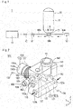
- Fig. 1 shows an example of use of a valve device 100 according to an embodiment.
- the valve device 100 is applied to a fuel cell system 1 that is provided in a fuel-cell vehicle.
- the valve device 100 is mounted to a high-pressure gas container 20 for storing a fuel gas (for example, a hydrogen gas) to be supplied to a fuel cell (fuel cell stack) 10.
- a fuel gas for example, a hydrogen gas
- the valve device 100 is used as an interception valve that switches between supply of a gas to the inside/outside of the high-pressure gas container 20 and interruption of the supply of the gas.
- the high-pressure gas cylinder 20 is connected to a receptacle (fueling port) 50 through the valve device 100 and a first pipe 60a.
- the high-pressure gas container 20 is connected to the fuel cell 10 through the valve device 100 and a second pipe 60b.
- a regulator 30 for regulating a flow rate of the gas to be supplied to the fuel cell 10 and a pressure regulating valve 40 for regulating a pressure of the gas are arranged in the second pipe 60b.
- the high-pressure gas container 20 includes: a container body 21 for storing a gas therein; and a supply port 23 that is provided in an end part on the one end side of the container body 21.
- the fuel-cell vehicle is equipped with the high-pressure gas container 20 together with, for example, the fuel cell 10.
- the container body 21, for example, can be formed of a publicly-known member that has a liner made of synthetic resin provided with a reinforcing layer such as glass fiber or carbon fiber.
- the supply port 23 of the high-pressure gas container 20 is configured as a mounting base to which the valve device 100 is detachably mounted (refer to Fig. 3 ).
- the high-pressure gas container 20, for example, is configured to be capable of storing a high-pressure gas having a maximum pressure of 70 MPa.
- the regulator 30, the pressure regulating valve 40 and the undermentioned electromagnetic actuator 140 of the valve device 100 can be subjected to the operation control by, for example, a control unit (controller) provided in the fuel-cell vehicle.
- the control unit can be configured by a publicly-known microcomputer that is provided with, for example, a CPU, a ROM, a RAM and various kinds of interfaces.
- the gas When a gas is supplied into the high-pressure gas container 20, the gas is caused to flow into the first pipe 60a through the receptacle 50 from, for example, an external facility such as a hydrogen station.
- the gas flows into the valve device 100 via the first pipe 60a.
- the gas further flows into the high-pressure gas container 20 via the valve device 100.
- the gas in the high-pressure gas cylinder 20 is caused to flow into the second pipe 60b through the valve device 100.
- the gas is supplied to the fuel cell 10 via the second pipe 60b.
- the regulator 30 regulates the gas to a desired flow rate and the pressure regulating valve 40 regulate the gas to a desired pressure.
- valve device 100 will be described in detail below with reference to Figs. 2 to 5 hereafter.
- Fig. 2 is a perspective view illustrating the valve device 100.
- Fig. 3 is a cross-sectional view schematically illustrating a structure inside the valve device 100.
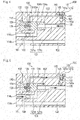
- Figs. 4 and 5 are magnified views of the part 4A indicated with the dash-dot line in Fig. 3 , and are diagrams illustrating the operation of the valve device 100. It should be noted that the configuration of the valve device 100 is partially simplified.
- the valve device 100 includes: a gas flow passage 120 that connects the supply port 23 of the high-pressure gas container 20 (refer to Fig. 3 ) and the fuel cell 10 to which the gas is supplied; an opening and closing valve 130 that is arranged in the gas flow passage 120, and switches between supply of the gas through the gas flow passage 120 and interruption of the supply; the electromagnetic actuator 140 that drives the opening and closing valve 130; and a gas discharge valve 160 that is provided with a valve body 161 operating in response to an increase in temperature of the gas, and discharges the gas to the outside of the high-pressure gas container 20.
- the valve device 100 is provided with a housing 110 having a gas flow passage 120 formed therein.
- the housing 110 includes a housing body 111 having a rectangular box shape, and an insertion part 113 having a cylindrical shape protruding from the one end side of the housing body 111.
- An X-axis shown in Fig. 2 indicates a width direction of the housing body 111
- a Y-axis indicates a depth direction of the housing body 111
- a Z-axis indicates a height direction of the housing body 111.
- the inside of the housing body 111 and the inside of the insertion part 113 are communicated with each other through the gas flow passage 120.
- the insertion part 113 When the valve device 100 is mounted to the high-pressure gas container 20, the insertion part 113 is inserted into the supply port 23.
- the insertion part 113 has a function as a fixing part that mechanically fixes the valve device 100 to the high-pressure gas container 20.
- the insertion part 113 is formed with a male screw part 113a that can be screwed to a female screw part 23a formed in an inner surface of the supply port 23 of the high-pressure gas container 20.
- the high-pressure gas container 20 and the valve device 100 are capable of connecting to each other through the screw part 23a and the screw part 113a.
- a material of the housing 110 (the housing body 111, the insertion part 113) is not particularly limited. Metallic materials can be used from the viewpoint of, for example, the processability, the strength and manufacturing costs.
- the housing 110 is formed of aluminum.
- the gas flow passage 120 formed inside the housing 110 includes: a first inflow opening 114a that is communicated with the supply port 23 of the high-pressure gas container 20; and a first flow passage 121 that is communicated with the first inflow opening 114a.
- An upstream side further being on an upper position than a position at which the undermentioned main valve 131 is arranged in the first flow passage 121 is referred to as "upstream part 121a" for reasons of convenience.
- a downstream side further being on a downstream position than the position at which the main valve 131 is arranged in the first flow passage 121 is referred to as "downstream part 121b" for reasons of convenience.
- the gas flow passage 120 further includes: a second inflow opening 114b that is communicated with the supply port 23 of the high-pressure gas container 20 at a position different from the position of the first inflow opening 114a; a gas introducing passage 122 that is communicated with the second inflow opening 114b; a communication passage 123 that is communicated with a first connection port 123a to which the first pipe 60a (refer to Fig. 1 ) is connected, and with a second connection port 123b to which the second pipe 60b (refer to Fig. 1 ) is connected; and a pilot flow passage 124 that is communicated between the undermentioned valve chamber 116 and the undermentioned pilot chamber 117.
- the first flow passage 121 is a flow passage through which a gas to be filled in the high-pressure gas container 20 and a gas to be supplied to the fuel cell 10 are circulated.
- the communication passage 123 is communicated with the downstream part 121b of the first flow passage 121 in the communication passage 123.
- the gas when a gas is supplied to the fuel cell 10, the gas is fed into the fuel cell 10 via the first inflow opening 114a, the first flow passage 121, the communication passage 123, the second connection port 123b and the second pipe 60b.
- the circulation path of the gas (gas flow) formed when the valve device 100 is operated will be described in detail later.
- an end surface 113b of the insertion part 113 of the housing 110 is formed with the first inflow opening 114a and the second inflow opening 114b.
- the first inflow opening 114a and the second inflow opening 114b can each be provided with a filter for preventing contamination or the like existing in the high-pressure gas cylinder 20 from flowing into the valve device 100.
- the downstream part 121b of the first flow passage 121 is provided with a manual valve 182 for adjusting (throttling) a flow rate of a gas flowing through the first flow passage 121.
- a manual valve 182 for adjusting (throttling) a flow rate of a gas flowing through the first flow passage 121.
- the gas introducing passage 122 is provided with a manual valve 181 for discharging the gas inside the high-pressure gas container 20 to the outside. By manually operating the manual valve 181, the gas can be discharged to the outside without operating the gas discharge valve 160.
- the opening and closing valve 130 is formed of a pilot-operated solenoid valve.
- the opening and closing valve 130 includes: the main valve 131 to which a biasing force in a valve closing direction that closes the first flow passage 121 is applied; and a pilot valve 141 for moving the main valve 131 in a valve opening direction that opens the first flow passage 121.
- the main valve 131 is arranged in the valve chamber 116 that is formed in the body part 111 of the housing 110.
- the valve chamber 116 is communicated with the first flow passage 121 (refer to Fig. 5 ) .
- a biasing member 135 applies a biasing force to the main valve 131 from the back-surface side (the left side in Fig. 3 ) toward the front surface side (the right side in Fig. 3 ).
- the main valve 131 with the biasing force applied is seated on the valve sheet 192 having an end side arranged in the first flow passage 121, and the main valve closes the first flow passage 121.
- the biasing member 135 can be formed of, for example, a publicly-known elastic member such as a spring.
- the biasing member 135 is supported by a support member 191 that is provided on the back-surface side of the main valve 131.
- the main valve 131 is formed with an internal space 132 inside, the internal space 132 being communicated with the pilot flow passage 124 through a circulation port 133.
- the other end side of the biasing member 135 is inserted into the internal space 132 of the main valve 131, and an end part on the other end side is fixed to the main valve 131.
- the end surface of the main valve 131 can be formed into a shape that has: a flat part 134a having a shape corresponding to a passage part of the valve sheet 192 so as to improve sealing characteristics when being seated on the valve sheet 192; and a tapered part 134b extending from the flat part 134a.
- the electromagnetic actuator 140 includes the pilot valve 141; a solenoidal coil (coil part) 142; a spring 143 that applies the biasing force in the valve-closing direction (downward direction in Fig. 3 ) to the pilot valve 141; a plug 144 constituting a fixed iron core; an actuator case 145 that houses the electromagnetic actuator 140 therein; and a lid part 146 that is arranged outside the housing 110.
- the pilot valve 141 is composed of: a plunger 141a that forms a moving core; and a seal part 141b that is arranged at the end of the plunger 141a.
- the seal part 141b can be formed of a publicly-known material, for example, a resinous elastic member (for example, O ring) or the like.
- the plunger 141a is arranged in such a manner that an end part of the plunger 141a faces the pilot chamber 117 formed on the front surface side of the plunger 141a.
- the plunger 141a is arranged so as to be capable of moving forward and backward in a direction (up-and-down direction in Fig. 3 ) in which the plunger 141a comes close to the valve sheetl93 and goes away from the valve sheet 193 in the actuator case 145.
- the biasing force applied from the spring 143 causes the plunger 141a to seat the seal part 141b on the valve sheet 193.
- the communication between the pilot flow passage 124 and a relay path 125 formed on the front surface side of the valve sheet 193 is interrupted.
- the pilot valve 141 When the pilot valve 141 is opened, a driving current is supplied to the solenoidal coil 142 to electrify the solenoidal coil 142. As a result of the electrification, a magnetic force for attracting the plunger 141a toward the plug 144 side is generated, which causes the plunger 141a, that is to say, the pilot valve 141, to move in a valve opening direction (upward direction in Fig. 3 ). Consequently, the pilot valve 141 goes away from the valve sheet 193 . As shown in Fig. 5 , when the pilot valve 141 goes away from the valve sheet 193, the passage part 193a formed in the valve sheet 193 is communicated with the pilot chamber 117. In addition, the valve chamber 116 in which the main valve 131 is arranged is communicated with the downstream part 121b of the first flow passage 121 through the pilot flow passage 124, the pilot chamber 117, the passage part 193a and the relay path 125.
- the gas discharge valve 160 is formed of a mechanically operated fusible plug valve (hereinafter referred to as "fusible plug valve 160") that opens by detecting a temperature of a gas in the high-pressure gas container 20.
- the fusible plug valve 160 includes : a valve body 161 formed of a fusible member; a valve body part 162 that houses the valve body 161, and has a bottom surface formed with an opening 165; a through-hole 163 that is communicated with the inside and outside of the valve body part 162; and a lid part 166 disposed outside the housing 110.
- the valve body 161 can be formed of, for example, publicly-known fusible alloy that melts when a predetermined temperature is reached.
- the valve body part 162 can be formed of, for example, heat-resistant glass.
- the outer peripheral surface of the valve body part 162 can be formed with, for example, a screw groove or the like that allows mounting to the housing 110.
- valve body 161 of the fusible plug valve 160 is arranged on the upstream side in the gas flow passage 120 than the opening and closing valve 130 with respect to a path through which the gas flows from the supply port 23 of the high-pressure gas container 20 toward the fuel cell 10.
- the above-described path through which the gas flows is a path ranging from the supply port 23 of the high-pressure gas container 20, and from the first inflow opening 114a of the high-pressure gas container 20, to the second connection port 123b.
- the upstream side in the gas flow passage 120 than the opening and closing valve 130 is the upstream side of the gas flow viewed from the main valve 131 that opens and closes the first flow passage 121.
- the upstream part 121a of the first flow passage 121 (the flow passage ranging from the first inflow opening 114a to the main valve 131 in the first flow passage 121), which is further on the upstream side than a position at which the main valve 131 is arranged, corresponds to the upstream side in the gas flow passage 120 than the opening and closing valve 130.
- the opening 165 formed in the valve body part 162 of the fusible plug valve 160 is formed is arranged so as to face the upstream part 121a of the first flow passage 121.
- the inside of the valve body part 162 is communicated with the upstream part 121a of the first flow passage 121 through the opening 165. Therefore, a bottom part of the valve body 161 housed in the valve body part 162 is arranged so as to face the inside of the upstream part 121a, and thus the bottom part is always exposed to the gas that exists in the upstream part 121a.
- the through-hole 163 formed in the valve body part 162 of the fusible plug valve 160 is communicated with a gas discharge passage 122a formed in the housing 110.
- the gas discharge passage 122a is connected to a gas discharge port 115 that is communicated with the outside of the housing 110.
- the heat of the gas is transferred to the valve body 161 of the fusible plug valve 160 through the upstream part 121a of the first flow passage 121.
- the valve body 161 melts.
- the opening 165 formed in the valve body part 162 is brought into an open state.
- the gas flows into the valve body part 162 from the opening 165 via the upstream part 121a of the first flow passage 121. Further, the gas flows into the gas discharge passage 122a via the through-hole 163 formed in the valve body part 162. Subsequently, the gas is discharged to the outside of the housing 110 through the gas discharge port 115 that is communicated with the gas discharge passage 122a.
- the opening and closing valve 130 (the main valve 131, the pilot valve 141) will be described with reference to Figs. 4 and 5 .
- Fig. 4 illustrates a state in which the opening and closing valve 130 closes the first flow passage 121.
- the regulator 30 and the pressure regulating valve 40 that are arranged in the second pipe 60b are each brought into an open state.
- a driving current is supplied to the solenoidal coil 142 of the electromagnetic actuator 140 to open the pilot valve 141 as shown in Fig. 5 .
- the valve chamber 116 in which the main valve 131 is arranged is communicated, through the pilot flow passage 124, with the pilot chamber 117 in which the pilot valve 141 is arranged. Further, the internal space 132 of the main valve 131 is communicated with the pilot flow passage 124 through the circulation port 133.
- the internal space 132 of the main valve 131 is communicated with the valve chamber 116 on the back-surface side of the main valve 131, and therefore the back pressure of the main valve 131 decreases to a pressure (downstream pressure) in the downstream part 121b of the first flow passage 121 and in the communication passage 123. As a result, the internal pressure of the high-pressure gas container 20 becomes higher than the back pressure of the main valve 131.
- a differential pressure between the back pressure of the main valve 131 and the internal pressure of the high-pressure gas container 20 generates a force for moving the main valve 131 in the valve opening direction against the biasing force applied to the main valve 131 by the biasing member 135, and consequently the main valve 131 goes away from the valve sheet 192.
- a clearance is formed between the valve sheet 192 and the main valve 131. The clearance allows the gas to circulate. Consequently, supply of the gas to the fuel cell 10 is started.
- the gas flows into the upstream part 121a of the first flow passage 121 from the supply port 23 of the high-pressure gas container 20 via the first inflow opening 114a. Subsequently, the gas flows toward the downstream part 121b of the first flow passage 121 via the periphery of the valve body 161 of the fusible plug valve 160 arranged in the upstream part 121a of the first flow passage 121.
- the valve body 161 of the fusible plug valve 160 comes in direct contact with the gas that flows from the high-pressure gas container 20 into the upstream part 121a of the first flow passage 121, and therefore the sensitivity of the valve body 161 with respect to a change in temperature of the gas is enhanced.
- the gas that flows around the valve body 161 of the fusible plug valve 160 has a heat-shielding effect of suppressing the heat generated by the electromagnetic actuator 140 from being transferred to the valve body 161. This enables to prevent the heat from being transferred to the valve body 161 while the driving current is supplied to the solenoidal coil 142 of the electromagnetic actuator 140. In this case, an effect of cooling the valve body 161 by the gas is also produced, and therefore the increase in temperature of the valve body 161 can be more effectively suppressed.
- Adding, for example, a cooling circuit or the like for cooling the electromagnetic actuator 140 to the valve device 100 also enables to prevent the heat generated by the electromagnetic actuator 140 from being transferred to the fusible plug valve 160.
- adding such a facility results in upsizing of the valve device 100 correspondingly.
- arranging the valve body 161 of the fusible plug valve 160 further on the upstream side in the gas flow passage 120 than the opening and closing valve 130 enables to prevent the fusible plug valve 160 from malfunctioning, and also enables to attempt the miniaturization of the device.
- the valve body 161 of the fusible plug valve 160 is arranged in the upstream part 121a of the first flow passage 121.
- the valve body 161 of the fusible plug valve 160 is located further on the upstream side than the main valve 131. Therefore, irrespective of whether the main valve 131 is in the open or closed state, the valve body 161 of the fusible plug valve 160 is brought into a state of being exposed to the gas that exists in the upstream part 121a of the first flow passage 121. Therefore, even when the temperature of the gas in the high-pressure gas container 20 has increased in a state in which the main valve 131 is closed, the fusible plug valve 160 can be operated, and thus the gas in the high-pressure gas container 20 can be properly discharged to the outside.
- the opening and closing valve 130 is arranged in the gas flow passage 120 provided with the valve device 100.
- the valve body 161 of the fusible plug valve 160 is arranged on the upstream side in the gas flow passage 120 than the opening and closing valve 130.
- valve body 161 is arranged on the upstream side of the gas flow passage 120 than the opening and closing valve 130, and therefore when the opening and closing valve 130 is operated to supply the gas, a flow of the gas passing around the valve body 161 of the fusible plug valve 160 can be preferably formed. This enables to enhance the sensitivity of the fusible plug valve 160 with respect to a change in temperature of the gas in the high-pressure gas container 20.
- valve body 161 of the fusible plug valve 160 is arranged in the gas flow, and therefore a heat-shielding effect produced by the gas flow enables to suppress the heat generated by the electromagnetic actuator 140 from being transferred to the fusible plug valve 160. Therefore, it is possible to provide the valve device 100 that, even in a case where the valve device 100 is miniaturized, is capable of preventing the fusible plug valve 160 from malfunctioning in response to the heat generated by the electromagnetic actuator 140.
- the opening and closing valve 130 includes: the main valve 131 that is arranged in the first flow passage 121 of the gas flow passage 120; and the pilot valve 141 for moving the main valve 131 in the valve opening direction that opens the first flow passage 121. Further, the valve body 161 of the fusible plug valve 160 is arranged on the upstream side in the gas flow passage 120 than the main valve 131.
- the valve device 100 enables to effectively suppress the heat generated by the electromagnetic actuator 140 from being transferred to the valve body 161 of the fusible plug valve 160.
- valve body 161 of the fusible plug valve 160 is arranged in the upstream part 121a of the first flow passage 121 ranging from the first inflow opening 114a to the upstream side of the main valve 131.
- the valve body 161 of the fusible plug valve 160 is configured to be arranged in the first flow passage 121 through which the gas inevitably circulates when the gas is supplied from the high-pressure gas container 20 to the fuel cell 10.
- the configuration made in this manner enables to arrange the valve body 161 of the fusible plug valve 160 in the path of the gas flow without additionally providing a flow passage, and therefore enables to provide the valve device 100 having a simple and easy structure.
- the gas discharge valve is configured by the fusible plug valve 160, the valve body 161 of which is formed of a fusible member. Therefore, the valve body 161 can be operated in response to an increase in temperature of the gas in the high-pressure gas container 20.
- the valve device 100 enables to quickly discharge the gas to the outside of the high-pressure gas container 20.
- a valve device 200 according to a second embodiment of the present invention will be described.
- features including a configuration which are not particularly explained, are the same as those of the valve device 100 according to the first embodiment described above.
- members having the same functions are denoted by the same reference numerals of the members respectively, and the description thereof will be omitted.
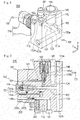
- Figs. 6 and 7 are diagrams each illustrating the valve device 200 according to the second embodiment.
- Fig. 6 is a perspective view illustrating the valve device 200.
- Fig. 7 is a cross-sectional view schematically illustrating a structure inside the valve device 200.
- valve body 161 of the fusible plug valve 160 is arranged on the upstream side in the gas flow passage 120 than the main valve 131 provided in the opening and closing valve 130.
- the valve body 161 of the fusible plug valve 160 is arranged in the upstream part 121a of the first flow passage 121 (the flow passage ranging from the first inflow opening 114a to the main valve 131).
- the valve body 161 of the fusible plug valve 160 is arranged in the first sub flow passage 222.
- the first sub flow passage 222 is provided so as to be communicated with the upstream part 121a of the first flow passage 121.
- the housing 210 is composed of a housing body 211 and an insertion part 213.
- the main valve 131 is mounted inside the insertion part 213.
- the first sub flow passage 222 is communicated with the supply port 23 (illustration is omitted) of the high-pressure gas container 20 through the second inflow opening 114b that is formed at a position different from the position of the first inflow opening 114a.
- the first sub flow passage 222 includes: an upstream part 222a in which the valve body 161 of the fusible plug valve 160 is arranged; and a downstream part 222b that is communicated between the upstream part 222a and the upstream part 121a of the first flow passage 121.
- the opening 165 formed with the valve body 162 of the fusible plug valve 160 is arranged so as to face the upstream part 222a of the first sub flow passage 222.
- the inside of the valve body 162 is communicated with the upstream part 222a of the first sub flow passage 222 through the opening 165. Therefore, a bottom part of the valve body 161 housed in the valve body part 162 is arranged so as to face the inside of the upstream part 222a.
- the bottom part of the valve body 161 is always exposed to the gas that exists in the upstream part 222a.
- the manual valve 181 for discharging the gas inside the high-pressure gas container 20 to the outside is arranged in the upstream part 222a of the first sub flow passage 222.
- the opening and closing valve 130 (the main valve 131, the pilot valve 141) is opened.
- the gas inside the high-pressure gas container 20 flows into the upstream part 121a of the first flow passage 121 through the first inflow opening 114a, and flows into the upstream part 222a of the first sub flow passage 222 through the second inflow opening 114b.
- the gas that has flowed into the upstream part 222a of the first sub flow passage 222 passes around the valve body 161 of the fusible plug valve 160, and then flows into the upstream part 121a of the first flow passage 121.
- a gas flow can be preferably formed around the valve body 161 of the fusible plug valve 160 that is arranged in the upstream part 222a of the first sub flow passage 222.
- the opening and closing valve 130 is arranged in the gas flow passage 120 provided in the valve device 100.
- the valve body 161 of the fusible plug valve 160 is arranged on the upstream side in the gas flow passage 120 than the opening and closing valve 130. More specifically, the first sub flow passage 222 that is communicated with the upstream part 121a of the first flow passage 121 is additionally provided, and the valve body 161 of the fusible plug valve 160 is arranged in the first sub flow passage 222.
- the valve device 200 enables to enhance the sensitivity of the valve body 161 with respect to a change in temperature of the gas in the high-pressure gas container 20, and enables to suppress the heat generated by the electromagnetic actuator 140 from being transferred to the valve body 161. Moreover, it is possible to prevent restrictions from being imposed on a mounting position of the fusible plug valve 160 under the influence of a layout of the first flow passage 121. Therefore the design flexibility of the valve device 200 can be increased.
- a position at which the valve body 161 of the fusible plug valve 160 is arranged is not particularly limited so long as the position that is in the first sub flow passage 222.
- the valve body 161 may be arranged at a position illustrated as the downstream part 222b.
- the fusible plug valve 160 can be preferably prevented from malfunctioning in response to the heat generated by the electromagnetic actuator 140.
- a valve device 300 according to a third embodiment of the present invention will be described.
- features including a configuration which are not particularly explained, are the same as those of each of the valve devices 100 and 200 according to the first and second embodiments described above respectively.
- members having the same functions are denoted by the same reference numerals of the members respectively, and the description thereof will be omitted.
- Fig. 8 is a cross-sectional view schematically illustrating a structure inside the valve device 300.
- valve body 161 of the fusible plug valve 160 is arranged on the upstream side in the gas flow passage 120 than the opening and closing valve 130.
- the valve body 161 of the fusible plug valve 160 is arranged on the upstream side in the gas flow passage 120 than the main valve 131 with reference to the main valve 131 provided in the opening and closing valve 130.
- the valve body 161 of the fusible plug valve 160 is arranged on the upstream side in the gas flow passage 120 than the pilot valve 141 with reference to the pilot valve 141 provided in the opening and closing valve 130.
- a housing 310 is composed of a housing body 311 and an insertion part 313.
- the main valve 131 is mounted inside the insertion part 313.
- the gas flow passage 120 includes a second sub flow passage 322.
- the second sub flow passage 322 is configured as a flow passage that connects the second inflow opening 114b formed at a position different from the position of the first inflow opening 114a to the pilot flow passage 124 on the upstream side than the pilot chamber 117.
- the second sub flow passage 322 includes an upstream part 322a in which the valve body 161 of the fusible plug valve 160 is arranged; and a downstream part 322b that is communicated between the upstream part 322a and the pilot flow passage 124.
- a flow passage diameter of a part of the second sub flow passage 322 is configured to be smaller than or equal to a flow passage diameter of the pilot flow passage 124.
- the part of the second sub flow passage 322 (a flow passage diameter of the downstream part 322b) is on the downstream side than the position at which the valve body 161 of the fusible plug valve 160 is arranged.
- the opening 165 formed with the valve body part 162 of the fusible plug valve 160 is arranged so as to face the upstream part 322a of the second sub flow passage 322.
- the inside of the valve body part 162 is communicated with the upstream part 322a of the second sub flow passage 322 through the opening 165. Therefore, a bottom part of the valve body 161 housed in the valve body part 162 is arranged so as to face the inside of the upstream part 322a.
- the bottom part of the valve body 161 is always exposed to the gas that exists in the upstream part 322a.
- the inside of the valve body part 162 is communicated with the gas discharge port 115 through the gas discharge passage 122a (illustration is omitted).
- the opening and closing valve 130 (the main valve 131, the pilot valve 141) is opened.
- the gas inside the high-pressure gas container 20 flows into the upstream part 121a of the first flow passage 121 through the first inflow opening 114a, and flows into the upstream part 322a of the second sub flow passage 322 through the second inflow opening 114b.
- the gas that has flowed into the upstream part 322a of the second sub flow passage 322 passes around the valve body 161 of the fusible plug valve 160, and then flows into the downstream part 322b of the second sub flow passage 322.
- a gas flow can be preferably formed around the valve body 161 of the fusible plug valve 160 that is arranged in the upstream part 322a of the second sub flow passage 322.
- the gas that has flowed into the downstream part 322b of the second sub flow passage 322 flows into the downstream part 121b of the first flow passage 121 via the pilot flow passage 124, the pilot chamber 117, the passage part 193a of the valve sheet 193, and the relay path 125.
- a flow passage diameter of the downstream part 322b of the second sub flow passage 322 is configured to be smaller than a flow passage diameter of the pilot flow passage 124. Therefore, the flow rate of the gas flowing into the downstream part 121b of the first flow passage 121 via the pilot flow passage 124 and the pilot chamber 117 is suppressed to be small in comparison with the flow rate of the gas flowing into the downstream part 121b of the first flow passage 121 via the main valve 131 side.
- the opening and closing valve 130 is arranged in the gas flow passage 120 provided in the valve device 100.
- the valve body 161 of the fusible plug valve 160 is arranged on the upstream side in the gas flow passage 120 than the pilot valve 141 provided in the opening and closing valve 130. More specifically, the valve body 161 of the fusible plug valve 160 is arranged in the second sub flow passage 322 that connects the second inflow opening 114b to the pilot flow passage 124 further on the upstream side than the pilot chamber 117.
- the pilot valve 141 operates to cause a gas to flow through the supply port 23 of the high-pressure gas container 20, the second inflow opening 114b, the second sub flow passage 322, and the pilot chamber 117, the gas flows toward the downstream side, and flows passing around the valve body 161 of the fusible plug valve 160 located on the upstream of the pilot valve 141. Therefore, a flow of the gas passing around the valve body 161 of the fusible plug valve 160 can be preferably formed in response to the operation of the pilot valve 141. Moreover, while the opening and closing valve 130 opens to supply the gas, the gas flowing around the valve body 161 of the fusible plug valve 160 shields the heat of the valve body 161.
- the gas flowing enables to effectively suppress the heat generated by the electromagnetic actuator 140 from being transferred to the valve body 161 of the fusible plug valve 160.
- the second sub flow passage 322 that connects the second inflow opening 114b and the pilot flow passage 124 is additionally provided, and the valve body 161 of the fusible plug valve 160 is arranged in the second sub flow passage 322. Therefore, it is possible to prevent restrictions from being imposed on a mounting position of the fusible plug valve 160. Therefore, the design flexibility of the valve device 300 can be increased.
- the flow passage diameter of the downstream part 322b of the second sub flow passage 322 is configured to be smaller than or equal to a flow passage diameter of the pilot flow passage 124. Therefore, a flow rate of the gas flowing into the first flow passage 121 via the pilot flow passage 124 and the pilot chamber 117 is suppressed to be small in comparison with the flow rate of the gas flowing into the downstream part 121b of the first flow passage 121 via the main valve 131 side.
- This enables to preferably prevent the durability of the pilot valve 141 (for example, the durability of the seal part 141b) from decreasing, and to preferably prevent a valve function from being impaired, as a result of additionally providing the second sub flow passage 322 that is connected to the pilot flow passage 124.
- a position at which the valve body 161 of the fusible plug valve 160 is arranged is not particularly limited so long as the position that is in the second sub flow passage 322.
- the valve body 161 may be arranged at a position illustrated as the downstream part 322b.
- the fusible plug valve 160 can be preferably prevented from malfunctioning in response to the heat generated by the electromagnetic actuator 140.
- valve device according to the present invention has been described in accordance with the embodiments described above.
- the present invention is not limited to the embodiments described herein, and can be modified as appropriate on the basis of the description of claims.
- the gas discharge valve is not limited to the fusible plug valve. Any valve may be used as the gas discharge valve so long as the valve to be used is a mechanically operated valve that opens by detecting a temperature of a gas in a high-pressure gas container.
- a thermosensitive valve provided with a valve body that reversibly opens and closes in response to a temperature of a gas can be used as the gas discharge valve.
- the valve described as the gas discharge valve has a configuration in which the gas is discharged to the outside through the flow passage (gas discharge passage) formed in the housing and the port (gas discharge port) formed in the housing.
- the gas discharge valve may be configured to cause a gas to pass through the inside of the gas discharge valve without passing through the flow passage and the port, and to cause the gas to be directly discharged to the outside.
- the valve device may be mounted to a high-pressure gas container other than the high-pressure gas container for storing a fuel gas that is supplied to an in-vehicle fuel cell.
- the valve device may be mounted to a high-pressure gas container for storing a natural gas.
- the opening and closing valve is not particularly limited so long as the opening and closing valve is driven by an electromagnetic actuator.
- the opening and closing valve may be a direct acting solenoid valve or a kick pilot solenoid valve.
- the valve described as the opening and closing valve has a configuration in which while a driving current is supplied to the electromagnetic actuator, the gas flow passage is opened to supply the gas, and while supply of the driving current to the electromagnetic actuator is stopped, the gas flow passage is closed to stop the supply of the gas.
- the opening and closing valve may be configured to operate in such a manner that while a driving current is supplied to the electromagnetic actuator, the gas flow passage is closed to stop the supply of the gas, and while supply of the driving current to the electromagnetic actuator is stopped, the gas flow passage is opened to supply the gas.
- valve body of the gas discharge valve is not particularly limited so long as the valve body of the gas discharge valve is arranged in the gas flow passage, and is arranged further on the upstream side in the path through which the gas flows than the opening and closing valve that switches the supply and interruption of the gas.
- the opening and closing valve is formed of a pilot-operated valve that is provided with a main valve and a pilot valve
- a gas discharge valve has only to be arranged at a position that is on the upstream side with respect to any one of the main valve and the pilot valve.
- a position at which the gas discharge valve is arranged is not particularly limited so long as the position is further on the upstream side than the opening and closing valve.
- valve device configurations of parts of the valve device, layouts of flow passages and the like are not limited to those illustrated in the figures.
- omission of the use of additional members shown in the embodiments, and the use of other additional members that have not been shown in the embodiments, may be performed as appropriate.
Landscapes
- Engineering & Computer Science (AREA)
- General Engineering & Computer Science (AREA)
- Mechanical Engineering (AREA)
- Filling Or Discharging Of Gas Storage Vessels (AREA)
- Fuel Cell (AREA)
- Magnetically Actuated Valves (AREA)
- Safety Valves (AREA)
- Valve Housings (AREA)
Abstract
Description
- The present invention relates to a valve device.
- Conventionally, there is known a valve device that controls a gas inflow and a gas outflow of a high-pressure gas container for storing a high-pressure gas. For example, the
undermentioned Patent Literature 1 describes a valve device that is mounted to a high-pressure gas container for storing a fuel gas to be supplied to a fuel cell. - The valve device described in the
Patent Literature 1 includes a gas flow passage that is communicated with the inside of a high-pressure gas container, and an electromagnetic driven-opening and closing valve that switches between opening and closing of the gas flow passage. When the opening and closing valve is operated, a driving current is supplied to an electromagnetic actuator as work for a driving source, so the operation of moving the opening and closing valve in a valve-opening direction is performed. - Incidentally, a valve device that is mounted to a high-pressure gas container may be provided with a mechanically operated safety valve (gas discharge valve) . The mechanically operated safety valve detects the temperature of the gas, when a temperature of a gas stored in the high-pressure gas container increases, and discharges the gas to the outside of the high-pressure gas container. It is also considered that, in the case of the above-described valve device including an electromagnetic driven valve body provided with such a safety valve enables to discharge the gas, the valve device discharges the gas to the outside in the proper timing in response to an increase in temperature of the gas.
- Patent Literature 1: Japanese Unexamined Patent Application Publication No.
2005-264966 - However, in a case where a safety valve such as that described above is mounted to a valve device that is provided with an electromagnetic driven valve body, the heat generated by a driving current supplied to an electromagnetic actuator is transferred to the safety valve. Therefore, there arises a possibility that the safety valve will malfunction.
- In addition, a high-pressure gas container tends to be miniaturized for more compact installation space, and for reduction in manufacturing costs. Similarly, a valve device that is mounted to the high-pressure gas container also requires miniaturization. However, in a case where the valve device is miniaturized, the safety valve is inevitably arranged in proximity to the electromagnetic actuator. Therefore, there exists a problem that the possibility that the safety valve will malfunction in response to the heat generated by the electromagnetic actuator further increases.
- Accordingly, an object of the present invention is to provide a valve device that, even in a case where the valve device is miniaturized, is capable of preventing a gas discharge valve from malfunctioning in response to the heat generated by an electromagnetic actuator.
- According to one aspect of the present invention, a valve device that is mounted to a high-pressure gas container is provided. The valve device includes: a gas flow passage that connects between a supply port of a high-pressure gas container and an object to which a gas is supplied; an opening and closing valve that is arranged in the gas flow passage, and switches between supply of the gas through the gas flow passage and interruption of the supply; an electromagnetic actuator that drives the opening and closing valve; and a gas discharge valve that is provided with a valve body operating in response to an increase in temperature of the gas, and discharges the gas to the outside of the high-pressure gas container. In addition, the valve body of the gas discharge valve is arranged on the upstream side in the gas flow passage than the opening and closing valve on a path through which the gas flows from the supply port toward the object.
- According to the above-described aspect, the valve body of the gas discharge valve is arranged in the gas flow passage through which a gas flows when the gas is supplied from the high-pressure gas container to the object. This enables to cause a gas around the valve body of the gas discharge valve to flow. In addition, the valve body of the gas discharge valve is arranged on the upstream side of the gas flow passage than the opening and closing valve, and therefore when the opening and closing valve is operated to supply a gas, a flow of the gas passing around the valve body of the gas discharge valve can be preferably formed. This enables to enhance the sensitivity of the gas discharge valve with respect to a change in temperature of the gas in the high-pressure gas container. Moreover, the valve body of the gas discharge valve is arranged in the gas flow, and a heat-shielding effect produced by the gas flow enables to suppress the heat generated by the electromagnetic actuator from being transferred to the valve body of the gas discharge valve. Therefore, it is possible to provide a valve device that, even in a case where the valve device is miniaturized, is capable of preventing a gas discharge valve from malfunctioning in response to the heat generated by an electromagnetic actuator.
-
-
Fig. 1 is a schematic diagram illustrating an example of use of a valve device according to an embodiment of the present invention. -
Fig. 2 is a perspective view illustrating a valve device according to a first embodiment of the present invention. -
Fig. 3 is a cross-sectional view illustrating a valve device according to the first embodiment of the present invention. -
Fig. 4 is a magnified view of apart 4A indicated with a dash-dot line inFig. 3 , and is a diagram illustrating a state in which an opening and closing valve closes a first flow passage. -
Fig. 5 is a magnified view of thepart 4A indicated with the dash-dot line inFig. 3 , and is a diagram illustrating a state in which the opening and closing valve opens the first flow passage. -
Fig. 6 is a perspective view illustrating a valve device according to a second embodiment of the present invention. -
Fig. 7 is a cross-sectional view illustrating the valve device according to the second embodiment of the present invention. -
Fig. 8 is a cross-sectional view illustrating the valve device according to a third embodiment of the present invention. - Embodiments of the present invention will be described below with reference to the accompanying drawings. It should be noted that in the explanation of the drawings, identical elements are denoted by identical reference numerals, and overlapping explanation will be omitted. In addition, size ratios in the drawings may be exaggerated for convenience of explanation, and thus may differ from the actual ratios.
-
Fig. 1 shows an example of use of avalve device 100 according to an embodiment. In this example of use, thevalve device 100 is applied to afuel cell system 1 that is provided in a fuel-cell vehicle. - The
valve device 100 is mounted to a high-pressure gas container 20 for storing a fuel gas (for example, a hydrogen gas) to be supplied to a fuel cell (fuel cell stack) 10. Thevalve device 100 is used as an interception valve that switches between supply of a gas to the inside/outside of the high-pressure gas container 20 and interruption of the supply of the gas. - The high-
pressure gas cylinder 20 is connected to a receptacle (fueling port) 50 through thevalve device 100 and afirst pipe 60a. - The high-
pressure gas container 20 is connected to thefuel cell 10 through thevalve device 100 and asecond pipe 60b. Aregulator 30 for regulating a flow rate of the gas to be supplied to thefuel cell 10 and apressure regulating valve 40 for regulating a pressure of the gas are arranged in thesecond pipe 60b. - The high-
pressure gas container 20 includes: acontainer body 21 for storing a gas therein; and asupply port 23 that is provided in an end part on the one end side of thecontainer body 21. - The fuel-cell vehicle is equipped with the high-
pressure gas container 20 together with, for example, thefuel cell 10. - The
container body 21, for example, can be formed of a publicly-known member that has a liner made of synthetic resin provided with a reinforcing layer such as glass fiber or carbon fiber. Thesupply port 23 of the high-pressure gas container 20 is configured as a mounting base to which thevalve device 100 is detachably mounted (refer toFig. 3 ). The high-pressure gas container 20, for example, is configured to be capable of storing a high-pressure gas having a maximum pressure of 70 MPa. - The
regulator 30, thepressure regulating valve 40 and the undermentionedelectromagnetic actuator 140 of thevalve device 100 can be subjected to the operation control by, for example, a control unit (controller) provided in the fuel-cell vehicle. The control unit can be configured by a publicly-known microcomputer that is provided with, for example, a CPU, a ROM, a RAM and various kinds of interfaces. - When a gas is supplied into the high-
pressure gas container 20, the gas is caused to flow into thefirst pipe 60a through thereceptacle 50 from, for example, an external facility such as a hydrogen station. The gas flows into thevalve device 100 via thefirst pipe 60a. The gas further flows into the high-pressure gas container 20 via thevalve device 100. - When the gas is supplied to the
fuel cell 10, the gas in the high-pressure gas cylinder 20 is caused to flow into thesecond pipe 60b through thevalve device 100. The gas is supplied to thefuel cell 10 via thesecond pipe 60b. When the gas goes through thesecond pipe 60b, theregulator 30 regulates the gas to a desired flow rate and thepressure regulating valve 40 regulate the gas to a desired pressure. - The
valve device 100 will be described in detail below with reference toFigs. 2 to 5 hereafter. -
Fig. 2 is a perspective view illustrating thevalve device 100.Fig. 3 is a cross-sectional view schematically illustrating a structure inside thevalve device 100.Figs. 4 and 5 are magnified views of thepart 4A indicated with the dash-dot line inFig. 3 , and are diagrams illustrating the operation of thevalve device 100. It should be noted that the configuration of thevalve device 100 is partially simplified. - The
valve device 100, with referenceFig.2 , includes: agas flow passage 120 that connects thesupply port 23 of the high-pressure gas container 20 (refer toFig. 3 ) and thefuel cell 10 to which the gas is supplied; an opening and closingvalve 130 that is arranged in thegas flow passage 120, and switches between supply of the gas through thegas flow passage 120 and interruption of the supply; theelectromagnetic actuator 140 that drives the opening and closingvalve 130; and agas discharge valve 160 that is provided with avalve body 161 operating in response to an increase in temperature of the gas, and discharges the gas to the outside of the high-pressure gas container 20. - As shown in
Fig. 2 , thevalve device 100 is provided with ahousing 110 having agas flow passage 120 formed therein. Thehousing 110 includes ahousing body 111 having a rectangular box shape, and aninsertion part 113 having a cylindrical shape protruding from the one end side of thehousing body 111. An X-axis shown inFig. 2 indicates a width direction of thehousing body 111, a Y-axis indicates a depth direction of thehousing body 111, and a Z-axis indicates a height direction of thehousing body 111. - As shown in
Fig. 3 , the inside of thehousing body 111 and the inside of theinsertion part 113 are communicated with each other through thegas flow passage 120. - When the
valve device 100 is mounted to the high-pressure gas container 20, theinsertion part 113 is inserted into thesupply port 23. Theinsertion part 113 has a function as a fixing part that mechanically fixes thevalve device 100 to the high-pressure gas container 20. Theinsertion part 113 is formed with amale screw part 113a that can be screwed to afemale screw part 23a formed in an inner surface of thesupply port 23 of the high-pressure gas container 20. The high-pressure gas container 20 and thevalve device 100 are capable of connecting to each other through thescrew part 23a and thescrew part 113a. - A material of the housing 110 (the
housing body 111, the insertion part 113) is not particularly limited. Metallic materials can be used from the viewpoint of, for example, the processability, the strength and manufacturing costs. In the present embodiment, thehousing 110 is formed of aluminum. - As shown in
Fig. 3 , thegas flow passage 120 formed inside thehousing 110 includes: afirst inflow opening 114a that is communicated with thesupply port 23 of the high-pressure gas container 20; and afirst flow passage 121 that is communicated with thefirst inflow opening 114a. An upstream side further being on an upper position than a position at which the undermentionedmain valve 131 is arranged in thefirst flow passage 121 is referred to as "upstream part 121a" for reasons of convenience. A downstream side further being on a downstream position than the position at which themain valve 131 is arranged in thefirst flow passage 121 is referred to as "downstream part 121b" for reasons of convenience. - The
gas flow passage 120 further includes: a second inflow opening 114b that is communicated with thesupply port 23 of the high-pressure gas container 20 at a position different from the position of thefirst inflow opening 114a; agas introducing passage 122 that is communicated with the second inflow opening 114b; acommunication passage 123 that is communicated with afirst connection port 123a to which thefirst pipe 60a (refer toFig. 1 ) is connected, and with asecond connection port 123b to which thesecond pipe 60b (refer toFig. 1 ) is connected; and apilot flow passage 124 that is communicated between theundermentioned valve chamber 116 and theundermentioned pilot chamber 117. - The
first flow passage 121 is a flow passage through which a gas to be filled in the high-pressure gas container 20 and a gas to be supplied to thefuel cell 10 are circulated. Thecommunication passage 123 is communicated with thedownstream part 121b of thefirst flow passage 121 in thecommunication passage 123. When a gas is filled in the high-pressure gas container 20, the gas is caused to flow into the high-pressure gas cylinder 20 via thefirst pipe 60a, thefirst connection port 123a, thecommunication passage 123, thefirst flow passage 121 and thefirst inflow opening 114a. Meanwhile, when a gas is supplied to thefuel cell 10, the gas is fed into thefuel cell 10 via thefirst inflow opening 114a, thefirst flow passage 121, thecommunication passage 123, thesecond connection port 123b and thesecond pipe 60b. Incidentally, the circulation path of the gas (gas flow) formed when thevalve device 100 is operated will be described in detail later. - As shown in
Fig. 2 , anend surface 113b of theinsertion part 113 of thehousing 110 is formed with thefirst inflow opening 114a and the second inflow opening 114b. Thefirst inflow opening 114a and thesecond inflow opening 114b can each be provided with a filter for preventing contamination or the like existing in the high-pressure gas cylinder 20 from flowing into thevalve device 100. - As shown in
Fig. 3 , thedownstream part 121b of thefirst flow passage 121 is provided with amanual valve 182 for adjusting (throttling) a flow rate of a gas flowing through thefirst flow passage 121. By manually operating themanual valve 182, the flow rate of the gas circulating through thefirst flow passage 121 can be adjusted without the operation of opening and closing the opening and closingvalve 130. - The
gas introducing passage 122 is provided with amanual valve 181 for discharging the gas inside the high-pressure gas container 20 to the outside. By manually operating themanual valve 181, the gas can be discharged to the outside without operating thegas discharge valve 160. - The opening and closing
valve 130 is formed of a pilot-operated solenoid valve. The opening and closingvalve 130 includes: themain valve 131 to which a biasing force in a valve closing direction that closes thefirst flow passage 121 is applied; and apilot valve 141 for moving themain valve 131 in a valve opening direction that opens thefirst flow passage 121. - The
main valve 131 is arranged in thevalve chamber 116 that is formed in thebody part 111 of thehousing 110. Thevalve chamber 116 is communicated with the first flow passage 121 (refer toFig. 5 ) . - A biasing
member 135 applies a biasing force to themain valve 131 from the back-surface side (the left side inFig. 3 ) toward the front surface side (the right side inFig. 3 ). Themain valve 131 with the biasing force applied is seated on thevalve sheet 192 having an end side arranged in thefirst flow passage 121, and the main valve closes thefirst flow passage 121. The biasingmember 135 can be formed of, for example, a publicly-known elastic member such as a spring. - The biasing
member 135 is supported by asupport member 191 that is provided on the back-surface side of themain valve 131. Themain valve 131 is formed with aninternal space 132 inside, theinternal space 132 being communicated with thepilot flow passage 124 through acirculation port 133. In a state in which the one end side of the biasingmember 135 is fixed to thesupport member 191, the other end side of the biasingmember 135 is inserted into theinternal space 132 of themain valve 131, and an end part on the other end side is fixed to themain valve 131. - As shown in
Fig. 4 , for example, the end surface of themain valve 131 can be formed into a shape that has: aflat part 134a having a shape corresponding to a passage part of thevalve sheet 192 so as to improve sealing characteristics when being seated on thevalve sheet 192; and atapered part 134b extending from theflat part 134a. - As shown in
Fig. 3 , theelectromagnetic actuator 140 includes thepilot valve 141; a solenoidal coil (coil part) 142; aspring 143 that applies the biasing force in the valve-closing direction (downward direction inFig. 3 ) to thepilot valve 141; aplug 144 constituting a fixed iron core; anactuator case 145 that houses theelectromagnetic actuator 140 therein; and alid part 146 that is arranged outside thehousing 110. - The
pilot valve 141 is composed of: aplunger 141a that forms a moving core; and aseal part 141b that is arranged at the end of theplunger 141a. Theseal part 141b can be formed of a publicly-known material, for example, a resinous elastic member (for example, O ring) or the like. - As shown in
Fig. 4 , theplunger 141a is arranged in such a manner that an end part of theplunger 141a faces thepilot chamber 117 formed on the front surface side of theplunger 141a. Theplunger 141a is arranged so as to be capable of moving forward and backward in a direction (up-and-down direction inFig. 3 ) in which theplunger 141a comes close to the valve sheetl93 and goes away from thevalve sheet 193 in theactuator case 145. - The biasing force applied from the
spring 143 causes theplunger 141a to seat theseal part 141b on thevalve sheet 193. In a state in which theseal part 141b is seated on thevalve sheet 193, the communication between thepilot flow passage 124 and arelay path 125 formed on the front surface side of thevalve sheet 193 is interrupted. - When the
pilot valve 141 is opened, a driving current is supplied to thesolenoidal coil 142 to electrify thesolenoidal coil 142. As a result of the electrification, a magnetic force for attracting theplunger 141a toward theplug 144 side is generated, which causes theplunger 141a, that is to say, thepilot valve 141, to move in a valve opening direction (upward direction inFig. 3 ). Consequently, thepilot valve 141 goes away from thevalve sheet 193 . As shown inFig. 5 , when thepilot valve 141 goes away from thevalve sheet 193, thepassage part 193a formed in thevalve sheet 193 is communicated with thepilot chamber 117. In addition, thevalve chamber 116 in which themain valve 131 is arranged is communicated with thedownstream part 121b of thefirst flow passage 121 through thepilot flow passage 124, thepilot chamber 117, thepassage part 193a and therelay path 125. - The
gas discharge valve 160 is formed of a mechanically operated fusible plug valve (hereinafter referred to as "fusible plug valve 160") that opens by detecting a temperature of a gas in the high-pressure gas container 20. - As shown in
Fig. 2 , thefusible plug valve 160 includes : avalve body 161 formed of a fusible member; avalve body part 162 that houses thevalve body 161, and has a bottom surface formed with anopening 165; a through-hole 163 that is communicated with the inside and outside of thevalve body part 162; and alid part 166 disposed outside thehousing 110. - The
valve body 161 can be formed of, for example, publicly-known fusible alloy that melts when a predetermined temperature is reached. Thevalve body part 162 can be formed of, for example, heat-resistant glass. The outer peripheral surface of thevalve body part 162 can be formed with, for example, a screw groove or the like that allows mounting to thehousing 110. - As shown in
Fig. 3 , thevalve body 161 of thefusible plug valve 160 is arranged on the upstream side in thegas flow passage 120 than the opening and closingvalve 130 with respect to a path through which the gas flows from thesupply port 23 of the high-pressure gas container 20 toward thefuel cell 10. - The above-described path through which the gas flows is a path ranging from the
supply port 23 of the high-pressure gas container 20, and from thefirst inflow opening 114a of the high-pressure gas container 20, to thesecond connection port 123b. In addition, further on the upstream side in thegas flow passage 120 than the opening and closingvalve 130 is the upstream side of the gas flow viewed from themain valve 131 that opens and closes thefirst flow passage 121. In the present embodiment, theupstream part 121a of the first flow passage 121 (the flow passage ranging from thefirst inflow opening 114a to themain valve 131 in the first flow passage 121), which is further on the upstream side than a position at which themain valve 131 is arranged, corresponds to the upstream side in thegas flow passage 120 than the opening and closingvalve 130. - As shown in
Fig. 2 , theopening 165 formed in thevalve body part 162 of thefusible plug valve 160 is formed is arranged so as to face theupstream part 121a of thefirst flow passage 121. The inside of thevalve body part 162 is communicated with theupstream part 121a of thefirst flow passage 121 through theopening 165. Therefore, a bottom part of thevalve body 161 housed in thevalve body part 162 is arranged so as to face the inside of theupstream part 121a, and thus the bottom part is always exposed to the gas that exists in theupstream part 121a. - As shown in
Fig. 2 , the through-hole 163 formed in thevalve body part 162 of thefusible plug valve 160 is communicated with agas discharge passage 122a formed in thehousing 110. Thegas discharge passage 122a is connected to agas discharge port 115 that is communicated with the outside of thehousing 110. - When a temperature of a gas in the high-
pressure gas container 20 increases, the heat of the gas is transferred to thevalve body 161 of thefusible plug valve 160 through theupstream part 121a of thefirst flow passage 121. When thevalve body 161 is heated to reach a predetermined temperature, thevalve body 161 melts. When thevalve body 161 melts, theopening 165 formed in thevalve body part 162 is brought into an open state. The gas flows into thevalve body part 162 from theopening 165 via theupstream part 121a of thefirst flow passage 121. Further, the gas flows into thegas discharge passage 122a via the through-hole 163 formed in thevalve body part 162. Subsequently, the gas is discharged to the outside of thehousing 110 through thegas discharge port 115 that is communicated with thegas discharge passage 122a. - The operation of the opening and closing valve 130 (the
main valve 131, the pilot valve 141) will be described with reference toFigs. 4 and 5 . -
Fig. 4 illustrates a state in which the opening and closingvalve 130 closes thefirst flow passage 121. - When a gas is filled in the high-
pressure gas container 20, feeding the gas into thevalve device 100 from thereceptacle 50 causes the gas to flow into thedownstream part 121b of thefirst flow passage 121 through the communication passage 123 (refer toFig. 3 ). In the early stage in which the gas is supplied to the high-pressure gas container 20, a force of the biasingmember 135 biases themain valve 131 toward thevalve sheet 192 maintains themain valve 131 in a state of being seated on thevalve sheet 192. Incidentally, when the gas is filled in the high-pressure gas container 20, theregulator 30 and thepressure regulating valve 40 that are arranged in thesecond pipe 60b (refer toFig. 1 ) are brought into a closed state. - When the gas is continuously supplied, a gas pressure in the
downstream part 121b of thefirst flow passage 121 and a gas pressure in thecommunication passage 123 gradually increase. In response to the increases in gas pressure, themain valve 131 moves back to the back-surface side against the biasing force of the biasingmember 135. When themain valve 131 goes away from thevalve sheet 192, a clearance is formed between thevalve sheet 192 and themain valve 131. The clearance allows the gas to circulate. Thefirst flow passage 121 in an open state causes the gas to flow into thedownstream part 121b of thefirst flow passage 121. Subsequently, the gas is filled in the high-pressure gas container 20 via thefirst inflow opening 114a and thesupply port 23 of the high-pressure gas container 20. - After filling of the gas in the high-
pressure gas container 20 is started, continues supply of the gas gradually increases an internal pressure of the high-pressure gas container 20. When a differential pressure between the internal pressure of the high-pressure gas container 20 and the filling pressure of the gas (the gas pressure in thedownstream part 121b of thefirst flow passage 121 and the gas pressure in the communication passage 123) becomes a little, the biasing force applied by the biasingmember 135 moves themain valve 131 in the valve closing direction, and themain valve 131 is seated on thevalve sheet 192 again as shown inFig. 4 . Themain valve 131 is seated on thevalve sheet 192 in a state of being biased by the biasingmember 135, and therefore prevents the gas from flowing backward from the high-pressure gas container 20 toward thefirst flow passage 121 side after filling of the gas ends. - When the gas is supplied to the
fuel cell 10, first, theregulator 30 and thepressure regulating valve 40 that are arranged in thesecond pipe 60b are each brought into an open state. Next, a driving current is supplied to thesolenoidal coil 142 of theelectromagnetic actuator 140 to open thepilot valve 141 as shown inFig. 5 . - When the
pilot valve 141 is opened, thevalve chamber 116 in which themain valve 131 is arranged is communicated, through thepilot flow passage 124, with thepilot chamber 117 in which thepilot valve 141 is arranged. Further, theinternal space 132 of themain valve 131 is communicated with thepilot flow passage 124 through thecirculation port 133. Theinternal space 132 of themain valve 131 is communicated with thevalve chamber 116 on the back-surface side of themain valve 131, and therefore the back pressure of themain valve 131 decreases to a pressure (downstream pressure) in thedownstream part 121b of thefirst flow passage 121 and in thecommunication passage 123. As a result, the internal pressure of the high-pressure gas container 20 becomes higher than the back pressure of themain valve 131. Subsequently, a differential pressure between the back pressure of themain valve 131 and the internal pressure of the high-pressure gas container 20 generates a force for moving themain valve 131 in the valve opening direction against the biasing force applied to themain valve 131 by the biasingmember 135, and consequently themain valve 131 goes away from thevalve sheet 192. When themain valve 131 goes away from thevalve sheet 192, a clearance is formed between thevalve sheet 192 and themain valve 131. The clearance allows the gas to circulate. Consequently, supply of the gas to thefuel cell 10 is started. - The gas flows into the
upstream part 121a of thefirst flow passage 121 from thesupply port 23 of the high-pressure gas container 20 via thefirst inflow opening 114a. Subsequently, the gas flows toward thedownstream part 121b of thefirst flow passage 121 via the periphery of thevalve body 161 of thefusible plug valve 160 arranged in theupstream part 121a of thefirst flow passage 121. In this case, thevalve body 161 of thefusible plug valve 160 comes in direct contact with the gas that flows from the high-pressure gas container 20 into theupstream part 121a of thefirst flow passage 121, and therefore the sensitivity of thevalve body 161 with respect to a change in temperature of the gas is enhanced. Moreover, the gas that flows around thevalve body 161 of thefusible plug valve 160 has a heat-shielding effect of suppressing the heat generated by theelectromagnetic actuator 140 from being transferred to thevalve body 161. This enables to prevent the heat from being transferred to thevalve body 161 while the driving current is supplied to thesolenoidal coil 142 of theelectromagnetic actuator 140. In this case, an effect of cooling thevalve body 161 by the gas is also produced, and therefore the increase in temperature of thevalve body 161 can be more effectively suppressed. - Adding, for example, a cooling circuit or the like for cooling the
electromagnetic actuator 140 to thevalve device 100 also enables to prevent the heat generated by theelectromagnetic actuator 140 from being transferred to thefusible plug valve 160. However, adding such a facility results in upsizing of thevalve device 100 correspondingly. In thevalve device 100, arranging thevalve body 161 of thefusible plug valve 160 further on the upstream side in thegas flow passage 120 than the opening and closingvalve 130 enables to prevent thefusible plug valve 160 from malfunctioning, and also enables to attempt the miniaturization of the device. - When supply of the gas to the
fuel cell 10 is stopped, the operation of closing theregulator 30, thepressure regulating valve 40 and thepilot valve 141 is performed. As a result of the operation, the biasing force applied by the biasingmember 135 moves themain valve 131 in the valve closing direction, and seats themain valve 131 on thevalve sheet 192 to close thefirst flow passage 121. - In the present embodiment, the
valve body 161 of thefusible plug valve 160 is arranged in theupstream part 121a of thefirst flow passage 121. Thevalve body 161 of thefusible plug valve 160 is located further on the upstream side than themain valve 131. Therefore, irrespective of whether themain valve 131 is in the open or closed state, thevalve body 161 of thefusible plug valve 160 is brought into a state of being exposed to the gas that exists in theupstream part 121a of thefirst flow passage 121. Therefore, even when the temperature of the gas in the high-pressure gas container 20 has increased in a state in which themain valve 131 is closed, thefusible plug valve 160 can be operated, and thus the gas in the high-pressure gas container 20 can be properly discharged to the outside. - As described above, in the present embodiment, the opening and closing
valve 130 is arranged in thegas flow passage 120 provided with thevalve device 100. In addition, on the path through which the gas flows from thesupply port 23 of the high-pressure gas container 20 toward thefuel cell 10, thevalve body 161 of thefusible plug valve 160 is arranged on the upstream side in thegas flow passage 120 than the opening and closingvalve 130. - This enables to cause the gas around the
valve body 161 of thefusible plug valve 160 to flow while the gas is supplied from the high-pressure gas container 20 to thefuel cell 10. In addition, thevalve body 161 is arranged on the upstream side of thegas flow passage 120 than the opening and closingvalve 130, and therefore when the opening and closingvalve 130 is operated to supply the gas, a flow of the gas passing around thevalve body 161 of thefusible plug valve 160 can be preferably formed. This enables to enhance the sensitivity of thefusible plug valve 160 with respect to a change in temperature of the gas in the high-pressure gas container 20. Moreover, thevalve body 161 of thefusible plug valve 160 is arranged in the gas flow, and therefore a heat-shielding effect produced by the gas flow enables to suppress the heat generated by theelectromagnetic actuator 140 from being transferred to thefusible plug valve 160. Therefore, it is possible to provide thevalve device 100 that, even in a case where thevalve device 100 is miniaturized, is capable of preventing thefusible plug valve 160 from malfunctioning in response to the heat generated by theelectromagnetic actuator 140. - In the present embodiment, the opening and closing
valve 130 includes: themain valve 131 that is arranged in thefirst flow passage 121 of thegas flow passage 120; and thepilot valve 141 for moving themain valve 131 in the valve opening direction that opens thefirst flow passage 121. Further, thevalve body 161 of thefusible plug valve 160 is arranged on the upstream side in thegas flow passage 120 than themain valve 131. - Therefore, when the
main valve 131 moves in the valve opening direction to open thefirst flow passage 121, with the result that the gas is supplied to thefuel cell 10 via thesupply port 23 of the high-pressure gas container 20, thefirst inflow opening 114a and thefirst flow passage 121, the gas flows toward the downstream side via the periphery of thefusible plug valve 160 located on the upstream side of themain valve 131. Therefore, a flow of the gas passing around thevalve body 161 of thefusible plug valve 160 can be preferably formed in response to the operation of themain valve 131. Moreover, while themain valve 131 opens to supply the gas, the gas flowing around thevalve body 161 of thefusible plug valve 160 shields the heat of thevalve body 161. Therefore, thevalve device 100 enables to effectively suppress the heat generated by theelectromagnetic actuator 140 from being transferred to thevalve body 161 of thefusible plug valve 160. - In addition, in the present embodiment, the
valve body 161 of thefusible plug valve 160 is arranged in theupstream part 121a of thefirst flow passage 121 ranging from thefirst inflow opening 114a to the upstream side of themain valve 131. In other words, thevalve body 161 of thefusible plug valve 160 is configured to be arranged in thefirst flow passage 121 through which the gas inevitably circulates when the gas is supplied from the high-pressure gas container 20 to thefuel cell 10. The configuration made in this manner enables to arrange thevalve body 161 of thefusible plug valve 160 in the path of the gas flow without additionally providing a flow passage, and therefore enables to provide thevalve device 100 having a simple and easy structure. - Furthermore, in the present embodiment, the gas discharge valve is configured by the
fusible plug valve 160, thevalve body 161 of which is formed of a fusible member. Therefore, thevalve body 161 can be operated in response to an increase in temperature of the gas in the high-pressure gas container 20. Thevalve device 100 enables to quickly discharge the gas to the outside of the high-pressure gas container 20. - A
valve device 200 according to a second embodiment of the present invention will be described. In the description of the present embodiment, features including a configuration, which are not particularly explained, are the same as those of thevalve device 100 according to the first embodiment described above. In addition, members having the same functions are denoted by the same reference numerals of the members respectively, and the description thereof will be omitted. -
Figs. 6 and 7 are diagrams each illustrating thevalve device 200 according to the second embodiment.Fig. 6 is a perspective view illustrating thevalve device 200.Fig. 7 is a cross-sectional view schematically illustrating a structure inside thevalve device 200. - In the
valve device 200 according to the second embodiment, as with thevalve device 100 according to the first embodiment, thevalve body 161 of thefusible plug valve 160 is arranged on the upstream side in thegas flow passage 120 than themain valve 131 provided in the opening and closingvalve 130. However, in thevalve device 100 according to the first embodiment, thevalve body 161 of thefusible plug valve 160 is arranged in theupstream part 121a of the first flow passage 121 (the flow passage ranging from thefirst inflow opening 114a to the main valve 131). Meanwhile, in thevalve device 200 according to the second embodiment, thevalve body 161 of thefusible plug valve 160 is arranged in the firstsub flow passage 222. The firstsub flow passage 222 is provided so as to be communicated with theupstream part 121a of thefirst flow passage 121. - As shown in
Figs. 6 and 7 , thehousing 210 is composed of ahousing body 211 and aninsertion part 213. Themain valve 131 is mounted inside theinsertion part 213. - The first
sub flow passage 222 is communicated with the supply port 23 (illustration is omitted) of the high-pressure gas container 20 through the second inflow opening 114b that is formed at a position different from the position of thefirst inflow opening 114a. The firstsub flow passage 222 includes: anupstream part 222a in which thevalve body 161 of thefusible plug valve 160 is arranged; and adownstream part 222b that is communicated between theupstream part 222a and theupstream part 121a of thefirst flow passage 121. - The
opening 165 formed with thevalve body 162 of thefusible plug valve 160 is arranged so as to face theupstream part 222a of the firstsub flow passage 222. The inside of thevalve body 162 is communicated with theupstream part 222a of the firstsub flow passage 222 through theopening 165. Therefore, a bottom part of thevalve body 161 housed in thevalve body part 162 is arranged so as to face the inside of theupstream part 222a. The bottom part of thevalve body 161 is always exposed to the gas that exists in theupstream part 222a. - The
manual valve 181 for discharging the gas inside the high-pressure gas container 20 to the outside is arranged in theupstream part 222a of the firstsub flow passage 222. - As shown in
Fig. 7 , when the gas is supplied to thefuel cell 10, the opening and closing valve 130 (themain valve 131, the pilot valve 141) is opened. The gas inside the high-pressure gas container 20 flows into theupstream part 121a of thefirst flow passage 121 through thefirst inflow opening 114a, and flows into theupstream part 222a of the firstsub flow passage 222 through the second inflow opening 114b. The gas that has flowed into theupstream part 222a of the firstsub flow passage 222 passes around thevalve body 161 of thefusible plug valve 160, and then flows into theupstream part 121a of thefirst flow passage 121. By operating the opening and closingvalve 130 to start the supply of the gas to thefuel cell 10 in this manner, a gas flow can be preferably formed around thevalve body 161 of thefusible plug valve 160 that is arranged in theupstream part 222a of the firstsub flow passage 222. - As described above, in the present embodiment, the opening and closing
valve 130 is arranged in thegas flow passage 120 provided in thevalve device 100. In addition, thevalve body 161 of thefusible plug valve 160 is arranged on the upstream side in thegas flow passage 120 than the opening and closingvalve 130. More specifically, the firstsub flow passage 222 that is communicated with theupstream part 121a of thefirst flow passage 121 is additionally provided, and thevalve body 161 of thefusible plug valve 160 is arranged in the firstsub flow passage 222. - Therefore, as with the
valve device 100 according to the first embodiment described above, thevalve device 200 enables to enhance the sensitivity of thevalve body 161 with respect to a change in temperature of the gas in the high-pressure gas container 20, and enables to suppress the heat generated by theelectromagnetic actuator 140 from being transferred to thevalve body 161. Moreover, it is possible to prevent restrictions from being imposed on a mounting position of thefusible plug valve 160 under the influence of a layout of thefirst flow passage 121. Therefore the design flexibility of thevalve device 200 can be increased. - It should be noted that a position at which the
valve body 161 of thefusible plug valve 160 is arranged is not particularly limited so long as the position that is in the firstsub flow passage 222. Thevalve body 161 may be arranged at a position illustrated as thedownstream part 222b. In this case as well, thefusible plug valve 160 can be preferably prevented from malfunctioning in response to the heat generated by theelectromagnetic actuator 140. - A
valve device 300 according to a third embodiment of the present invention will be described. In the description of the present embodiment, features including a configuration, which are not particularly explained, are the same as those of each of thevalve devices -
Fig. 8 is a cross-sectional view schematically illustrating a structure inside thevalve device 300. - In the
valve device 300 according to the third embodiment, as with thevalve devices valve body 161 of thefusible plug valve 160 is arranged on the upstream side in thegas flow passage 120 than the opening and closingvalve 130. However, in thevalve devices valve body 161 of thefusible plug valve 160 is arranged on the upstream side in thegas flow passage 120 than themain valve 131 with reference to themain valve 131 provided in the opening and closingvalve 130. Meanwhile, in thevalve device 300 according to the third embodiment, thevalve body 161 of thefusible plug valve 160 is arranged on the upstream side in thegas flow passage 120 than thepilot valve 141 with reference to thepilot valve 141 provided in the opening and closingvalve 130. - As shown in
Fig. 8 , ahousing 310 is composed of ahousing body 311 and aninsertion part 313. Themain valve 131 is mounted inside theinsertion part 313. - The
gas flow passage 120 includes a secondsub flow passage 322. The secondsub flow passage 322 is configured as a flow passage that connects the second inflow opening 114b formed at a position different from the position of thefirst inflow opening 114a to thepilot flow passage 124 on the upstream side than thepilot chamber 117. - The second
sub flow passage 322 includes anupstream part 322a in which thevalve body 161 of thefusible plug valve 160 is arranged; and adownstream part 322b that is communicated between theupstream part 322a and thepilot flow passage 124. - A flow passage diameter of a part of the second
sub flow passage 322 is configured to be smaller than or equal to a flow passage diameter of thepilot flow passage 124. The part of the second sub flow passage 322 (a flow passage diameter of thedownstream part 322b) is on the downstream side than the position at which thevalve body 161 of thefusible plug valve 160 is arranged. By configuring the flow passage diameter of thedownstream part 322b to be such a size, a flow rate of the gas flowing into thepilot flow passage 124 from thedownstream part 322b can be small. - The
opening 165 formed with thevalve body part 162 of thefusible plug valve 160 is arranged so as to face theupstream part 322a of the secondsub flow passage 322. The inside of thevalve body part 162 is communicated with theupstream part 322a of the secondsub flow passage 322 through theopening 165. Therefore, a bottom part of thevalve body 161 housed in thevalve body part 162 is arranged so as to face the inside of theupstream part 322a. The bottom part of thevalve body 161 is always exposed to the gas that exists in theupstream part 322a. Incidentally, the inside of thevalve body part 162 is communicated with thegas discharge port 115 through thegas discharge passage 122a (illustration is omitted). - As shown in
Fig. 8 , when the gas is supplied to thefuel cell 10, the opening and closing valve 130 (themain valve 131, the pilot valve 141) is opened. The gas inside the high-pressure gas container 20 flows into theupstream part 121a of thefirst flow passage 121 through thefirst inflow opening 114a, and flows into theupstream part 322a of the secondsub flow passage 322 through the second inflow opening 114b. The gas that has flowed into theupstream part 322a of the secondsub flow passage 322 passes around thevalve body 161 of thefusible plug valve 160, and then flows into thedownstream part 322b of the secondsub flow passage 322. By operating the opening and closingvalve 130 to start the supply of the gas to thefuel cell 10 in this manner, a gas flow can be preferably formed around thevalve body 161 of thefusible plug valve 160 that is arranged in theupstream part 322a of the secondsub flow passage 322. - The gas that has flowed into the
downstream part 322b of the secondsub flow passage 322 flows into thedownstream part 121b of thefirst flow passage 121 via thepilot flow passage 124, thepilot chamber 117, thepassage part 193a of thevalve sheet 193, and therelay path 125. - A flow passage diameter of the
downstream part 322b of the secondsub flow passage 322 is configured to be smaller than a flow passage diameter of thepilot flow passage 124. Therefore, the flow rate of the gas flowing into thedownstream part 121b of thefirst flow passage 121 via thepilot flow passage 124 and thepilot chamber 117 is suppressed to be small in comparison with the flow rate of the gas flowing into thedownstream part 121b of thefirst flow passage 121 via themain valve 131 side. - As described above, in the present embodiment, the opening and closing
valve 130 is arranged in thegas flow passage 120 provided in thevalve device 100. In addition, thevalve body 161 of thefusible plug valve 160 is arranged on the upstream side in thegas flow passage 120 than thepilot valve 141 provided in the opening and closingvalve 130. More specifically, thevalve body 161 of thefusible plug valve 160 is arranged in the secondsub flow passage 322 that connects the second inflow opening 114b to thepilot flow passage 124 further on the upstream side than thepilot chamber 117. - As a result, when the
pilot valve 141 operates to cause a gas to flow through thesupply port 23 of the high-pressure gas container 20, the second inflow opening 114b, the secondsub flow passage 322, and thepilot chamber 117, the gas flows toward the downstream side, and flows passing around thevalve body 161 of thefusible plug valve 160 located on the upstream of thepilot valve 141. Therefore, a flow of the gas passing around thevalve body 161 of thefusible plug valve 160 can be preferably formed in response to the operation of thepilot valve 141. Moreover, while the opening and closingvalve 130 opens to supply the gas, the gas flowing around thevalve body 161 of thefusible plug valve 160 shields the heat of thevalve body 161. The gas flowing enables to effectively suppress the heat generated by theelectromagnetic actuator 140 from being transferred to thevalve body 161 of thefusible plug valve 160. In addition, the secondsub flow passage 322 that connects the second inflow opening 114b and thepilot flow passage 124 is additionally provided, and thevalve body 161 of thefusible plug valve 160 is arranged in the secondsub flow passage 322. Therefore, it is possible to prevent restrictions from being imposed on a mounting position of thefusible plug valve 160. Therefore, the design flexibility of thevalve device 300 can be increased. - In addition, in the present embodiment, the flow passage diameter of the
downstream part 322b of the secondsub flow passage 322 is configured to be smaller than or equal to a flow passage diameter of thepilot flow passage 124. Therefore, a flow rate of the gas flowing into thefirst flow passage 121 via thepilot flow passage 124 and thepilot chamber 117 is suppressed to be small in comparison with the flow rate of the gas flowing into thedownstream part 121b of thefirst flow passage 121 via themain valve 131 side. This enables to preferably prevent the durability of the pilot valve 141 (for example, the durability of theseal part 141b) from decreasing, and to preferably prevent a valve function from being impaired, as a result of additionally providing the secondsub flow passage 322 that is connected to thepilot flow passage 124. - It should be noted that a position at which the
valve body 161 of thefusible plug valve 160 is arranged is not particularly limited so long as the position that is in the secondsub flow passage 322. Thevalve body 161 may be arranged at a position illustrated as thedownstream part 322b. In this case as well, thefusible plug valve 160 can be preferably prevented from malfunctioning in response to the heat generated by theelectromagnetic actuator 140. - The valve device according to the present invention has been described in accordance with the embodiments described above. However, the present invention is not limited to the embodiments described herein, and can be modified as appropriate on the basis of the description of claims.
- For example, the gas discharge valve is not limited to the fusible plug valve. Any valve may be used as the gas discharge valve so long as the valve to be used is a mechanically operated valve that opens by detecting a temperature of a gas in a high-pressure gas container. For example, a thermosensitive valve provided with a valve body that reversibly opens and closes in response to a temperature of a gas can be used as the gas discharge valve. In addition, in the description of the embodiments, the valve described as the gas discharge valve has a configuration in which the gas is discharged to the outside through the flow passage (gas discharge passage) formed in the housing and the port (gas discharge port) formed in the housing. However, the gas discharge valve may be configured to cause a gas to pass through the inside of the gas discharge valve without passing through the flow passage and the port, and to cause the gas to be directly discharged to the outside.
- Moreover, for example, the valve device may be mounted to a high-pressure gas container other than the high-pressure gas container for storing a fuel gas that is supplied to an in-vehicle fuel cell. For example, the valve device may be mounted to a high-pressure gas container for storing a natural gas.
- In addition, for example, the opening and closing valve is not particularly limited so long as the opening and closing valve is driven by an electromagnetic actuator. The opening and closing valve may be a direct acting solenoid valve or a kick pilot solenoid valve.
- Moreover, in the description of the embodiments, the valve described as the opening and closing valve has a configuration in which while a driving current is supplied to the electromagnetic actuator, the gas flow passage is opened to supply the gas, and while supply of the driving current to the electromagnetic actuator is stopped, the gas flow passage is closed to stop the supply of the gas. However, the opening and closing valve may be configured to operate in such a manner that while a driving current is supplied to the electromagnetic actuator, the gas flow passage is closed to stop the supply of the gas, and while supply of the driving current to the electromagnetic actuator is stopped, the gas flow passage is opened to supply the gas.
- Further, the valve body of the gas discharge valve is not particularly limited so long as the valve body of the gas discharge valve is arranged in the gas flow passage, and is arranged further on the upstream side in the path through which the gas flows than the opening and closing valve that switches the supply and interruption of the gas. For example, as shown in the embodiment, in a case where the opening and closing valve is formed of a pilot-operated valve that is provided with a main valve and a pilot valve, a gas discharge valve has only to be arranged at a position that is on the upstream side with respect to any one of the main valve and the pilot valve. In addition, in a case where the opening and closing valve is formed of a valve other than the pilot-operated valve (for example, in the case of a direct acting valve), a position at which the gas discharge valve is arranged is not particularly limited so long as the position is further on the upstream side than the opening and closing valve.
- Furthermore, configurations of parts of the valve device, layouts of flow passages and the like are not limited to those illustrated in the figures. For example, the omission of the use of additional members shown in the embodiments, and the use of other additional members that have not been shown in the embodiments, may be performed as appropriate.
-
- 10
- Fuel cell (object)
- 20
- High-pressure gas container
- 23
- Gas supply port
- 100
- Valve device
- 114a
- First inflow opening
- 114b
- Second inflow opening
- 116
- Valve chamber
- 117
- Pilot chamber
- 120
- Gas flow passage
- 121
- The first flow passage
- 121a
- Upstream part of first flow passage
- 121b
- Downstream part of first flow passage
- 124
- Pilot flow passage
- 130
- Opening and closing valve
- 131
- Main valve
- 140
- Electromagnetic actuator
- 141
- Pilot valve
- 141a
- Plunger
- 160
- Fusible plug valve (gas discharge valve)
- 161
- Valve body (fusible member)
- 200
- Valve device
- 222
- First sub flow passage
- 222a
- Upstream part of first sub flow passage
- 222b
- Downstream part of first sub flow passage
- 300
- Valve device
- 322
- Second sub flow passage
- 322a
- Upstream part of second sub flow passage
- 322b
- Downstream part of second sub flow passage
Claims (7)
- A valve device that is mounted to a high-pressure gas container, the valve device comprising:a gas flow passage that connects a supply port of the high-pressure gas container and an object to which a gas is supplied;an opening and closing valve that is arranged in the gas flow passage, and switches between supply of the gas through the gas flow passage and interruption of the supply;an electromagnetic actuator that drives the opening and closing valve; anda gas discharge valve that is provided with a valve body operating in response to an increase in temperature of the gas, and discharges the gas to the outside of the high-pressure gas container,wherein the valve body of the gas discharge valve is arranged on the upstream side in the gas flow passage than the opening and closing valve on a path through which the gas flows from the supply port toward the object.
- The valve device according to claim 1, wherein:the gas flow passage includesa first inflow opening that is communicated with the supply port, anda first flow passage that is communicated with the first inflow opening;the opening and closing valve includesa main valve to which a biasing force in a valve closing direction that closes the first flow passage is applied, anda pilot valve that generates a force against the biasing force in response to an operation of a plunger provided in the electromagnetic actuator, and moves the main valve in a valve opening direction that opens the first flow passage; andthe valve body of the gas discharge valve is arranged on the upstream side in the gas flow passage than the main valve.
- The valve device according to claim 2, wherein:
the valve body of the gas discharge valve is arranged in the first flow passage ranging from the first inflow opening to the upstream side of the main valve. - The valve device according to claim 2, wherein:the gas flow passage includesa second inflow opening that is communicated with the supply port at a position different from a position of the first inflow opening, anda first sub flow passage that connects the second inflow opening and the first flow passage on the upstream side than a position at which the main valve is arranged; andthe valve body of the gas discharge valve is arranged in the first sub flow passage.
- The valve device according to claim 1, wherein:the gas flow passage includesa first inflow opening that is communicated with the supply port, anda first flow passage that is communicated with the first inflow opening;the opening and closing valve includesa main valve to which a biasing force in a valve closing direction that closes the first flow passage is applied, anda pilot valve that generates a force against the biasing force in response to an operation of a plunger provided in the electromagnetic actuator, and moves the main valve in a valve opening direction that opens the first flow passage;the gas flow passage further includesa second inflow opening that is communicated with the supply port at a position different from a position of the first inflow opening,a pilot flow passage that connects a pilot chamber that is communicated with the first flow passage, and in which the pilot valve is arranged, and a valve chamber in which the main valve is arranged, anda second sub flow passage that connects the second inflow opening and the pilot flow passage on the upstream side than the pilot chamber; andthe valve body of the gas discharge valve is arranged in the second sub flow passage.
- The valve device according to claim 5, wherein
a flow passage diameter of the second sub flow passage on the downstream side than a position at which the valve body of the gas discharge valve is arranged is smaller than or equal to a flow passage diameter of the pilot flow passage. - The valve device according to any one of claims 1 to 6, wherein
the gas discharge valve is a fusible plug valve, the valve body of which is formed of a fusible member.
Applications Claiming Priority (1)
| Application Number | Priority Date | Filing Date | Title |
|---|---|---|---|
| PCT/JP2015/070334 WO2017009992A1 (en) | 2015-07-15 | 2015-07-15 | Valve device |
Publications (3)
| Publication Number | Publication Date |
|---|---|
| EP3324086A1 true EP3324086A1 (en) | 2018-05-23 |
| EP3324086A4 EP3324086A4 (en) | 2018-06-06 |
| EP3324086B1 EP3324086B1 (en) | 2019-09-11 |
Family
ID=57758012
Family Applications (1)
| Application Number | Title | Priority Date | Filing Date |
|---|---|---|---|
| EP15898304.9A Active EP3324086B1 (en) | 2015-07-15 | 2015-07-15 | Valve device |
Country Status (7)
| Country | Link |
|---|---|
| US (1) | US10260681B2 (en) |
| EP (1) | EP3324086B1 (en) |
| JP (1) | JP6460240B2 (en) |
| KR (1) | KR101918903B1 (en) |
| CN (1) | CN107850230B (en) |
| CA (1) | CA2992536C (en) |
| WO (1) | WO2017009992A1 (en) |
Families Citing this family (13)
| Publication number | Priority date | Publication date | Assignee | Title |
|---|---|---|---|---|
| KR102453794B1 (en) * | 2018-07-24 | 2022-10-12 | 가부시키가이샤 후지킨 | Valve device, fluid control device, fluid control method, semiconductor manufacturing device and semiconductor manufacturing method |
| CN110993993B (en) * | 2019-11-29 | 2021-06-18 | 山东明宇新能源技术有限公司 | Fuel cell sightseeing vehicle |
| DE102020200679A1 (en) * | 2020-01-22 | 2021-07-22 | Robert Bosch Gesellschaft mit beschränkter Haftung | Method for opening a valve assembly for a fuel tank |
| DE102020201170A1 (en) * | 2020-01-31 | 2021-08-05 | Robert Bosch Gesellschaft mit beschränkter Haftung | Valve system and pressure accumulator with one valve system |
| JP7350669B2 (en) * | 2020-02-12 | 2023-09-26 | 日本サーモスタット株式会社 | Cooling water temperature control device |
| JP7350668B2 (en) * | 2020-02-12 | 2023-09-26 | 日本サーモスタット株式会社 | Valve unit |
| CN113357424B (en) * | 2020-03-02 | 2025-03-28 | 上海气立可气动设备有限公司 | Thin electric proportional valve with quick exhaust valve |
| IT202000008932A1 (en) * | 2020-04-24 | 2021-10-24 | Omb Saleri S P A | MULTIFUNCTION VALVE FOR FUEL CELL AUTOTRACTION SYSTEMS |
| DE102020209664A1 (en) * | 2020-07-30 | 2022-02-03 | Robert Bosch Gesellschaft mit beschränkter Haftung | Compressed gas storage device, vehicle with compressed gas storage device |
| KR102430936B1 (en) * | 2020-10-19 | 2022-08-08 | 주식회사 엔케이 | Connection plug for high pressure gas storage container and Support device comprising the same |
| CN113503467B (en) * | 2021-07-08 | 2023-07-25 | 亚普汽车部件(开封)有限公司 | High-pressure gas cylinder valve for vehicle |
| KR102367816B1 (en) * | 2021-08-31 | 2022-02-24 | 박중수 | Supersonic Wind Tunnel Flow Control Valve System |
| DE102024205896A1 (en) | 2024-06-25 | 2026-01-08 | Robert Bosch Gesellschaft mit beschränkter Haftung | Tank valve for a fuel gas tank and fuel gas tank |
Family Cites Families (20)
| Publication number | Priority date | Publication date | Assignee | Title |
|---|---|---|---|---|
| JPS5363014U (en) * | 1976-10-30 | 1978-05-27 | ||
| US5452738A (en) * | 1994-02-22 | 1995-09-26 | Amcast Industrial Corporation | Crashworthy solenoid actuated valve for CNG powered vehicle |
| JP2762253B2 (en) | 1996-01-31 | 1998-06-04 | 本田技研工業株式会社 | Compressed natural gas filling equipment |
| US5820102A (en) | 1996-10-15 | 1998-10-13 | Superior Valve Company | Pressurized fluid storge and transfer system including a sonic nozzle |
| JP2002115798A (en) * | 2000-10-06 | 2002-04-19 | Neriki:Kk | Valve device |
| US20030041899A1 (en) * | 2001-09-04 | 2003-03-06 | The Coleman Company, Inc. | Pressurized gas canister |
| JP4088457B2 (en) * | 2002-02-26 | 2008-05-21 | 株式会社ネリキ | Safety valve for pressure vessel |
| DE10362052A1 (en) | 2003-10-21 | 2005-09-08 | Klaus Dipl.-Ing. Perthel | Electromagnetic valve for vehicle gas cylinders has externally threaded casing which screws into cylinder ands has central bore, in which piston and electromagnetic controls are mounted which are fitted through top of bore |
| US7309113B2 (en) | 2003-11-18 | 2007-12-18 | Dynetek Industries Ltd. | Flow control system for a valve |
| JP4558357B2 (en) | 2004-03-16 | 2010-10-06 | 本田技研工業株式会社 | Fluid fuel filling method |
| JP4496477B2 (en) * | 2005-03-01 | 2010-07-07 | トヨタ自動車株式会社 | Valve assembly for gas container |
| JP4872331B2 (en) * | 2005-12-05 | 2012-02-08 | トヨタ自動車株式会社 | Fuel cell system and method for stopping the same |
| JP4874948B2 (en) * | 2007-12-28 | 2012-02-15 | トヨタ自動車株式会社 | Safety valve device, valve device, high-pressure gas tank, and vehicle |
| JP5386249B2 (en) * | 2009-07-03 | 2014-01-15 | トヨタ自動車株式会社 | Valve device for high-pressure tank for vehicles |
| CN101958423A (en) * | 2010-09-25 | 2011-01-26 | 华为技术有限公司 | Hydrogen supply system, system and method for supplying hydrogen and hydrogen fuel cell system |
| DE102012206604A1 (en) | 2012-04-20 | 2013-10-24 | Hyptec Gmbh | Electromagnetic valve for a tank valve of a fuel supply system |
| CN104321575B (en) * | 2012-06-04 | 2016-04-27 | 永都产业株式会社 | Valve Assemblies for Fluid Control |
| CN203326037U (en) * | 2012-12-28 | 2013-12-04 | 清华大学 | Cathode exhaust gas recirculation system used for proton exchange membrane fuel cell (PEMFC) |
| JP5946438B2 (en) * | 2013-11-19 | 2016-07-06 | 株式会社鷺宮製作所 | On-off valve |
| JP6477316B2 (en) * | 2015-07-15 | 2019-03-06 | 日産自動車株式会社 | Valve device |
-
2015
- 2015-07-15 EP EP15898304.9A patent/EP3324086B1/en active Active
- 2015-07-15 US US15/744,493 patent/US10260681B2/en not_active Expired - Fee Related
- 2015-07-15 WO PCT/JP2015/070334 patent/WO2017009992A1/en not_active Ceased
- 2015-07-15 CA CA2992536A patent/CA2992536C/en active Active
- 2015-07-15 JP JP2017528249A patent/JP6460240B2/en not_active Expired - Fee Related
- 2015-07-15 KR KR1020187001237A patent/KR101918903B1/en not_active Expired - Fee Related
- 2015-07-15 CN CN201580081719.5A patent/CN107850230B/en not_active Expired - Fee Related
Also Published As
| Publication number | Publication date |
|---|---|
| JPWO2017009992A1 (en) | 2018-04-05 |
| CN107850230A (en) | 2018-03-27 |
| US20180209588A1 (en) | 2018-07-26 |
| WO2017009992A1 (en) | 2017-01-19 |
| CA2992536A1 (en) | 2017-01-19 |
| JP6460240B2 (en) | 2019-01-30 |
| CA2992536C (en) | 2019-03-05 |
| KR20180018731A (en) | 2018-02-21 |
| CN107850230B (en) | 2019-03-08 |
| EP3324086B1 (en) | 2019-09-11 |
| US10260681B2 (en) | 2019-04-16 |
| EP3324086A4 (en) | 2018-06-06 |
| KR101918903B1 (en) | 2018-11-14 |
Similar Documents
| Publication | Publication Date | Title |
|---|---|---|
| EP3324086B1 (en) | Valve device | |
| KR102635238B1 (en) | Valve device for gaseous medium and tank device for storing gaseous medium | |
| CN103180645B (en) | Hydrogen supply device for fuel cell system | |
| US11940100B2 (en) | Tank device for storing a gaseous medium | |
| US12397692B2 (en) | Pump valve module and method for operating the same, solenoid valve-based pump valve module for providing massage function for vehicle seat, and vehicle seat | |
| CN105308375B (en) | Pressure-control valve and control valve | |
| JP7580581B2 (en) | Tank arrangement for storing a gaseous medium with a valve arrangement - Patent application | |
| JP7656696B2 (en) | Tank arrangement for storing a gaseous medium with a valve arrangement - Patent application | |
| JP7569945B2 (en) | Fuel cell system, gas tank device, and shutoff valve for gas tank device | |
| JP2015516550A (en) | Solenoid valve assembly with back pressure control | |
| US20150361924A1 (en) | Regulator having electronic valve installed therein | |
| CN113404914B (en) | Electromagnetic valve | |
| JP6477316B2 (en) | Valve device | |
| US7717400B2 (en) | Fluid pressure regulating device | |
| US20250347347A1 (en) | Valve assembly | |
| JP7674910B2 (en) | Current supply control device and current supply control method for pressure reducing valve device | |
| CN107131165B (en) | Solenoid valve and pressure fluid control equipment | |
| JP7841363B2 (en) | non-return valve | |
| JP7831595B2 (en) | Valve assembly | |
| JP7696021B2 (en) | Shut-off valves for hydrogen tank systems, compressed gas cylinders and hydrogen tank systems | |
| JP6282214B2 (en) | Fuel supply unit | |
| JP2009127469A (en) | Fuel-feeding system and three-way valve | |
| JP2010127337A (en) | Motor safety valve | |
| CN120344792A (en) | Over-current prevention valve device and valve assembly |
Legal Events
| Date | Code | Title | Description |
|---|---|---|---|
| STAA | Information on the status of an ep patent application or granted ep patent |
Free format text: STATUS: THE INTERNATIONAL PUBLICATION HAS BEEN MADE |
|
| PUAI | Public reference made under article 153(3) epc to a published international application that has entered the european phase |
Free format text: ORIGINAL CODE: 0009012 |
|
| STAA | Information on the status of an ep patent application or granted ep patent |
Free format text: STATUS: REQUEST FOR EXAMINATION WAS MADE |
|
| 17P | Request for examination filed |
Effective date: 20180115 |
|
| AK | Designated contracting states |
Kind code of ref document: A1 Designated state(s): AL AT BE BG CH CY CZ DE DK EE ES FI FR GB GR HR HU IE IS IT LI LT LU LV MC MK MT NL NO PL PT RO RS SE SI SK SM TR |
|
| AX | Request for extension of the european patent |
Extension state: BA ME |
|
| A4 | Supplementary search report drawn up and despatched |
Effective date: 20180507 |
|
| RIC1 | Information provided on ipc code assigned before grant |
Ipc: F16K 31/06 20060101AFI20180430BHEP |
|
| DAV | Request for validation of the european patent (deleted) | ||
| DAX | Request for extension of the european patent (deleted) | ||
| GRAP | Despatch of communication of intention to grant a patent |
Free format text: ORIGINAL CODE: EPIDOSNIGR1 |
|
| STAA | Information on the status of an ep patent application or granted ep patent |
Free format text: STATUS: GRANT OF PATENT IS INTENDED |
|
| INTG | Intention to grant announced |
Effective date: 20190606 |
|
| GRAS | Grant fee paid |
Free format text: ORIGINAL CODE: EPIDOSNIGR3 |
|
| GRAA | (expected) grant |
Free format text: ORIGINAL CODE: 0009210 |
|
| STAA | Information on the status of an ep patent application or granted ep patent |
Free format text: STATUS: THE PATENT HAS BEEN GRANTED |
|
| AK | Designated contracting states |
Kind code of ref document: B1 Designated state(s): AL AT BE BG CH CY CZ DE DK EE ES FI FR GB GR HR HU IE IS IT LI LT LU LV MC MK MT NL NO PL PT RO RS SE SI SK SM TR |
|
| REG | Reference to a national code |
Ref country code: GB Ref legal event code: FG4D |
|
| REG | Reference to a national code |
Ref country code: CH Ref legal event code: EP |
|
| REG | Reference to a national code |
Ref country code: AT Ref legal event code: REF Ref document number: 1178863 Country of ref document: AT Kind code of ref document: T Effective date: 20190915 |
|
| REG | Reference to a national code |
Ref country code: DE Ref legal event code: R096 Ref document number: 602015038058 Country of ref document: DE Ref country code: IE Ref legal event code: FG4D |
|
| REG | Reference to a national code |
Ref country code: NL Ref legal event code: MP Effective date: 20190911 |
|
| REG | Reference to a national code |
Ref country code: LT Ref legal event code: MG4D |
|
| PG25 | Lapsed in a contracting state [announced via postgrant information from national office to epo] |
Ref country code: LT Free format text: LAPSE BECAUSE OF FAILURE TO SUBMIT A TRANSLATION OF THE DESCRIPTION OR TO PAY THE FEE WITHIN THE PRESCRIBED TIME-LIMIT Effective date: 20190911 Ref country code: FI Free format text: LAPSE BECAUSE OF FAILURE TO SUBMIT A TRANSLATION OF THE DESCRIPTION OR TO PAY THE FEE WITHIN THE PRESCRIBED TIME-LIMIT Effective date: 20190911 Ref country code: BG Free format text: LAPSE BECAUSE OF FAILURE TO SUBMIT A TRANSLATION OF THE DESCRIPTION OR TO PAY THE FEE WITHIN THE PRESCRIBED TIME-LIMIT Effective date: 20191211 Ref country code: HR Free format text: LAPSE BECAUSE OF FAILURE TO SUBMIT A TRANSLATION OF THE DESCRIPTION OR TO PAY THE FEE WITHIN THE PRESCRIBED TIME-LIMIT Effective date: 20190911 Ref country code: SE Free format text: LAPSE BECAUSE OF FAILURE TO SUBMIT A TRANSLATION OF THE DESCRIPTION OR TO PAY THE FEE WITHIN THE PRESCRIBED TIME-LIMIT Effective date: 20190911 Ref country code: NO Free format text: LAPSE BECAUSE OF FAILURE TO SUBMIT A TRANSLATION OF THE DESCRIPTION OR TO PAY THE FEE WITHIN THE PRESCRIBED TIME-LIMIT Effective date: 20191211 |
|
| PG25 | Lapsed in a contracting state [announced via postgrant information from national office to epo] |
Ref country code: RS Free format text: LAPSE BECAUSE OF FAILURE TO SUBMIT A TRANSLATION OF THE DESCRIPTION OR TO PAY THE FEE WITHIN THE PRESCRIBED TIME-LIMIT Effective date: 20190911 Ref country code: ES Free format text: LAPSE BECAUSE OF FAILURE TO SUBMIT A TRANSLATION OF THE DESCRIPTION OR TO PAY THE FEE WITHIN THE PRESCRIBED TIME-LIMIT Effective date: 20190911 Ref country code: LV Free format text: LAPSE BECAUSE OF FAILURE TO SUBMIT A TRANSLATION OF THE DESCRIPTION OR TO PAY THE FEE WITHIN THE PRESCRIBED TIME-LIMIT Effective date: 20190911 Ref country code: GR Free format text: LAPSE BECAUSE OF FAILURE TO SUBMIT A TRANSLATION OF THE DESCRIPTION OR TO PAY THE FEE WITHIN THE PRESCRIBED TIME-LIMIT Effective date: 20191212 Ref country code: AL Free format text: LAPSE BECAUSE OF FAILURE TO SUBMIT A TRANSLATION OF THE DESCRIPTION OR TO PAY THE FEE WITHIN THE PRESCRIBED TIME-LIMIT Effective date: 20190911 |
|
| REG | Reference to a national code |
Ref country code: AT Ref legal event code: MK05 Ref document number: 1178863 Country of ref document: AT Kind code of ref document: T Effective date: 20190911 |
|
| PG25 | Lapsed in a contracting state [announced via postgrant information from national office to epo] |
Ref country code: AT Free format text: LAPSE BECAUSE OF FAILURE TO SUBMIT A TRANSLATION OF THE DESCRIPTION OR TO PAY THE FEE WITHIN THE PRESCRIBED TIME-LIMIT Effective date: 20190911 Ref country code: NL Free format text: LAPSE BECAUSE OF FAILURE TO SUBMIT A TRANSLATION OF THE DESCRIPTION OR TO PAY THE FEE WITHIN THE PRESCRIBED TIME-LIMIT Effective date: 20190911 Ref country code: PL Free format text: LAPSE BECAUSE OF FAILURE TO SUBMIT A TRANSLATION OF THE DESCRIPTION OR TO PAY THE FEE WITHIN THE PRESCRIBED TIME-LIMIT Effective date: 20190911 Ref country code: RO Free format text: LAPSE BECAUSE OF FAILURE TO SUBMIT A TRANSLATION OF THE DESCRIPTION OR TO PAY THE FEE WITHIN THE PRESCRIBED TIME-LIMIT Effective date: 20190911 Ref country code: EE Free format text: LAPSE BECAUSE OF FAILURE TO SUBMIT A TRANSLATION OF THE DESCRIPTION OR TO PAY THE FEE WITHIN THE PRESCRIBED TIME-LIMIT Effective date: 20190911 Ref country code: IT Free format text: LAPSE BECAUSE OF FAILURE TO SUBMIT A TRANSLATION OF THE DESCRIPTION OR TO PAY THE FEE WITHIN THE PRESCRIBED TIME-LIMIT Effective date: 20190911 Ref country code: PT Free format text: LAPSE BECAUSE OF FAILURE TO SUBMIT A TRANSLATION OF THE DESCRIPTION OR TO PAY THE FEE WITHIN THE PRESCRIBED TIME-LIMIT Effective date: 20200113 |
|
| PG25 | Lapsed in a contracting state [announced via postgrant information from national office to epo] |
Ref country code: SM Free format text: LAPSE BECAUSE OF FAILURE TO SUBMIT A TRANSLATION OF THE DESCRIPTION OR TO PAY THE FEE WITHIN THE PRESCRIBED TIME-LIMIT Effective date: 20190911 Ref country code: SK Free format text: LAPSE BECAUSE OF FAILURE TO SUBMIT A TRANSLATION OF THE DESCRIPTION OR TO PAY THE FEE WITHIN THE PRESCRIBED TIME-LIMIT Effective date: 20190911 Ref country code: IS Free format text: LAPSE BECAUSE OF FAILURE TO SUBMIT A TRANSLATION OF THE DESCRIPTION OR TO PAY THE FEE WITHIN THE PRESCRIBED TIME-LIMIT Effective date: 20200224 Ref country code: CZ Free format text: LAPSE BECAUSE OF FAILURE TO SUBMIT A TRANSLATION OF THE DESCRIPTION OR TO PAY THE FEE WITHIN THE PRESCRIBED TIME-LIMIT Effective date: 20190911 |
|
| REG | Reference to a national code |
Ref country code: DE Ref legal event code: R097 Ref document number: 602015038058 Country of ref document: DE |
|
| PLBE | No opposition filed within time limit |
Free format text: ORIGINAL CODE: 0009261 |
|
| STAA | Information on the status of an ep patent application or granted ep patent |
Free format text: STATUS: NO OPPOSITION FILED WITHIN TIME LIMIT |
|
| PG2D | Information on lapse in contracting state deleted |
Ref country code: IS |
|
| PG25 | Lapsed in a contracting state [announced via postgrant information from national office to epo] |
Ref country code: DK Free format text: LAPSE BECAUSE OF FAILURE TO SUBMIT A TRANSLATION OF THE DESCRIPTION OR TO PAY THE FEE WITHIN THE PRESCRIBED TIME-LIMIT Effective date: 20190911 Ref country code: IS Free format text: LAPSE BECAUSE OF FAILURE TO SUBMIT A TRANSLATION OF THE DESCRIPTION OR TO PAY THE FEE WITHIN THE PRESCRIBED TIME-LIMIT Effective date: 20200112 |
|
| 26N | No opposition filed |
Effective date: 20200615 |
|
| PG25 | Lapsed in a contracting state [announced via postgrant information from national office to epo] |
Ref country code: SI Free format text: LAPSE BECAUSE OF FAILURE TO SUBMIT A TRANSLATION OF THE DESCRIPTION OR TO PAY THE FEE WITHIN THE PRESCRIBED TIME-LIMIT Effective date: 20190911 |
|
| PG25 | Lapsed in a contracting state [announced via postgrant information from national office to epo] |
Ref country code: MC Free format text: LAPSE BECAUSE OF FAILURE TO SUBMIT A TRANSLATION OF THE DESCRIPTION OR TO PAY THE FEE WITHIN THE PRESCRIBED TIME-LIMIT Effective date: 20190911 |
|
| REG | Reference to a national code |
Ref country code: CH Ref legal event code: PL |
|
| REG | Reference to a national code |
Ref country code: BE Ref legal event code: MM Effective date: 20200731 |
|
| PG25 | Lapsed in a contracting state [announced via postgrant information from national office to epo] |
Ref country code: LI Free format text: LAPSE BECAUSE OF NON-PAYMENT OF DUE FEES Effective date: 20200731 Ref country code: LU Free format text: LAPSE BECAUSE OF NON-PAYMENT OF DUE FEES Effective date: 20200715 Ref country code: CH Free format text: LAPSE BECAUSE OF NON-PAYMENT OF DUE FEES Effective date: 20200731 |
|
| PG25 | Lapsed in a contracting state [announced via postgrant information from national office to epo] |
Ref country code: BE Free format text: LAPSE BECAUSE OF NON-PAYMENT OF DUE FEES Effective date: 20200731 |
|
| PG25 | Lapsed in a contracting state [announced via postgrant information from national office to epo] |
Ref country code: IE Free format text: LAPSE BECAUSE OF NON-PAYMENT OF DUE FEES Effective date: 20200715 |
|
| PG25 | Lapsed in a contracting state [announced via postgrant information from national office to epo] |
Ref country code: TR Free format text: LAPSE BECAUSE OF FAILURE TO SUBMIT A TRANSLATION OF THE DESCRIPTION OR TO PAY THE FEE WITHIN THE PRESCRIBED TIME-LIMIT Effective date: 20190911 Ref country code: MT Free format text: LAPSE BECAUSE OF FAILURE TO SUBMIT A TRANSLATION OF THE DESCRIPTION OR TO PAY THE FEE WITHIN THE PRESCRIBED TIME-LIMIT Effective date: 20190911 Ref country code: CY Free format text: LAPSE BECAUSE OF FAILURE TO SUBMIT A TRANSLATION OF THE DESCRIPTION OR TO PAY THE FEE WITHIN THE PRESCRIBED TIME-LIMIT Effective date: 20190911 |
|
| PG25 | Lapsed in a contracting state [announced via postgrant information from national office to epo] |
Ref country code: MK Free format text: LAPSE BECAUSE OF FAILURE TO SUBMIT A TRANSLATION OF THE DESCRIPTION OR TO PAY THE FEE WITHIN THE PRESCRIBED TIME-LIMIT Effective date: 20190911 |
|
| PGFP | Annual fee paid to national office [announced via postgrant information from national office to epo] |
Ref country code: GB Payment date: 20220526 Year of fee payment: 8 Ref country code: FR Payment date: 20220510 Year of fee payment: 8 |
|
| PGFP | Annual fee paid to national office [announced via postgrant information from national office to epo] |
Ref country code: DE Payment date: 20220524 Year of fee payment: 8 |
|
| REG | Reference to a national code |
Ref country code: DE Ref legal event code: R119 Ref document number: 602015038058 Country of ref document: DE |
|
| GBPC | Gb: european patent ceased through non-payment of renewal fee |
Effective date: 20230715 |
|
| PG25 | Lapsed in a contracting state [announced via postgrant information from national office to epo] |
Ref country code: DE Free format text: LAPSE BECAUSE OF NON-PAYMENT OF DUE FEES Effective date: 20240201 Ref country code: GB Free format text: LAPSE BECAUSE OF NON-PAYMENT OF DUE FEES Effective date: 20230715 |
|
| PG25 | Lapsed in a contracting state [announced via postgrant information from national office to epo] |
Ref country code: FR Free format text: LAPSE BECAUSE OF NON-PAYMENT OF DUE FEES Effective date: 20230731 |