EP3324077A1 - Ball screw, machine tool, and conveying device - Google Patents
Ball screw, machine tool, and conveying device Download PDFInfo
- Publication number
- EP3324077A1 EP3324077A1 EP16824387.1A EP16824387A EP3324077A1 EP 3324077 A1 EP3324077 A1 EP 3324077A1 EP 16824387 A EP16824387 A EP 16824387A EP 3324077 A1 EP3324077 A1 EP 3324077A1
- Authority
- EP
- European Patent Office
- Prior art keywords
- ball screw
- nut body
- covering member
- peripheral surface
- rolling
- Prior art date
- Legal status (The legal status is an assumption and is not a legal conclusion. Google has not performed a legal analysis and makes no representation as to the accuracy of the status listed.)
- Granted
Links
- 230000002093 peripheral effect Effects 0.000 claims abstract description 43
- 238000005096 rolling process Methods 0.000 claims abstract description 32
- 229920003002 synthetic resin Polymers 0.000 claims abstract description 10
- 239000000057 synthetic resin Substances 0.000 claims abstract description 10
- 238000004519 manufacturing process Methods 0.000 abstract description 5
- 230000001629 suppression Effects 0.000 abstract description 3
- 229910000831 Steel Inorganic materials 0.000 description 8
- 239000010959 steel Substances 0.000 description 8
- 229910000967 As alloy Inorganic materials 0.000 description 4
- 238000010586 diagram Methods 0.000 description 4
- 239000000463 material Substances 0.000 description 4
- 238000000034 method Methods 0.000 description 4
- 238000001746 injection moulding Methods 0.000 description 3
- 229920001707 polybutylene terephthalate Polymers 0.000 description 3
- 229920006324 polyoxymethylene Polymers 0.000 description 3
- 229920005989 resin Polymers 0.000 description 3
- 239000011347 resin Substances 0.000 description 3
- 229910000851 Alloy steel Inorganic materials 0.000 description 2
- 239000004417 polycarbonate Substances 0.000 description 2
- 229920000515 polycarbonate Polymers 0.000 description 2
- 229930182556 Polyacetal Natural products 0.000 description 1
- 230000000694 effects Effects 0.000 description 1
- 238000005516 engineering process Methods 0.000 description 1
- 238000002347 injection Methods 0.000 description 1
- 239000007924 injection Substances 0.000 description 1
- -1 polybutylene terephthalate Polymers 0.000 description 1
- 239000000243 solution Substances 0.000 description 1
Images


Classifications
-
- F—MECHANICAL ENGINEERING; LIGHTING; HEATING; WEAPONS; BLASTING
- F16—ENGINEERING ELEMENTS AND UNITS; GENERAL MEASURES FOR PRODUCING AND MAINTAINING EFFECTIVE FUNCTIONING OF MACHINES OR INSTALLATIONS; THERMAL INSULATION IN GENERAL
- F16H—GEARING
- F16H25/00—Gearings comprising primarily only cams, cam-followers and screw-and-nut mechanisms
- F16H25/18—Gearings comprising primarily only cams, cam-followers and screw-and-nut mechanisms for conveying or interconverting oscillating or reciprocating motions
- F16H25/20—Screw mechanisms
- F16H25/22—Screw mechanisms with balls, rollers, or similar members between the co-operating parts; Elements essential to the use of such members
- F16H25/2204—Screw mechanisms with balls, rollers, or similar members between the co-operating parts; Elements essential to the use of such members with balls
- F16H25/2214—Screw mechanisms with balls, rollers, or similar members between the co-operating parts; Elements essential to the use of such members with balls with elements for guiding the circulating balls
-
- F—MECHANICAL ENGINEERING; LIGHTING; HEATING; WEAPONS; BLASTING
- F16—ENGINEERING ELEMENTS AND UNITS; GENERAL MEASURES FOR PRODUCING AND MAINTAINING EFFECTIVE FUNCTIONING OF MACHINES OR INSTALLATIONS; THERMAL INSULATION IN GENERAL
- F16H—GEARING
- F16H25/00—Gearings comprising primarily only cams, cam-followers and screw-and-nut mechanisms
- F16H25/18—Gearings comprising primarily only cams, cam-followers and screw-and-nut mechanisms for conveying or interconverting oscillating or reciprocating motions
- F16H25/20—Screw mechanisms
- F16H25/24—Elements essential to such mechanisms, e.g. screws, nuts
-
- F—MECHANICAL ENGINEERING; LIGHTING; HEATING; WEAPONS; BLASTING
- F16—ENGINEERING ELEMENTS AND UNITS; GENERAL MEASURES FOR PRODUCING AND MAINTAINING EFFECTIVE FUNCTIONING OF MACHINES OR INSTALLATIONS; THERMAL INSULATION IN GENERAL
- F16H—GEARING
- F16H25/00—Gearings comprising primarily only cams, cam-followers and screw-and-nut mechanisms
- F16H25/18—Gearings comprising primarily only cams, cam-followers and screw-and-nut mechanisms for conveying or interconverting oscillating or reciprocating motions
- F16H25/20—Screw mechanisms
- F16H25/24—Elements essential to such mechanisms, e.g. screws, nuts
- F16H2025/2481—Special features for facilitating the manufacturing of spindles, nuts, or sleeves of screw devices
-
- F—MECHANICAL ENGINEERING; LIGHTING; HEATING; WEAPONS; BLASTING
- F16—ENGINEERING ELEMENTS AND UNITS; GENERAL MEASURES FOR PRODUCING AND MAINTAINING EFFECTIVE FUNCTIONING OF MACHINES OR INSTALLATIONS; THERMAL INSULATION IN GENERAL
- F16H—GEARING
- F16H25/00—Gearings comprising primarily only cams, cam-followers and screw-and-nut mechanisms
- F16H25/18—Gearings comprising primarily only cams, cam-followers and screw-and-nut mechanisms for conveying or interconverting oscillating or reciprocating motions
- F16H25/20—Screw mechanisms
- F16H25/24—Elements essential to such mechanisms, e.g. screws, nuts
- F16H2025/249—Materials or coatings for screws or nuts
-
- F—MECHANICAL ENGINEERING; LIGHTING; HEATING; WEAPONS; BLASTING
- F16—ENGINEERING ELEMENTS AND UNITS; GENERAL MEASURES FOR PRODUCING AND MAINTAINING EFFECTIVE FUNCTIONING OF MACHINES OR INSTALLATIONS; THERMAL INSULATION IN GENERAL
- F16H—GEARING
- F16H25/00—Gearings comprising primarily only cams, cam-followers and screw-and-nut mechanisms
- F16H25/18—Gearings comprising primarily only cams, cam-followers and screw-and-nut mechanisms for conveying or interconverting oscillating or reciprocating motions
- F16H25/20—Screw mechanisms
- F16H25/22—Screw mechanisms with balls, rollers, or similar members between the co-operating parts; Elements essential to the use of such members
- F16H25/2204—Screw mechanisms with balls, rollers, or similar members between the co-operating parts; Elements essential to the use of such members with balls
- F16H25/2214—Screw mechanisms with balls, rollers, or similar members between the co-operating parts; Elements essential to the use of such members with balls with elements for guiding the circulating balls
- F16H25/2219—Axially mounted end-deflectors
Definitions
- the present invention relates to a ball screw and a machine tool and a conveying device that use the ball screw.
- a ball screw includes a nut with a helical groove formed on the inner peripheral surface thereof, a screw shaft with a helical groove formed on the outer peripheral surface thereof, and a ball return path for returning balls placed on a track formed between the helical groove of the nut and the helical groove of the screw shaft from the end point to the starting point of the track.
- the balls roll through the track, thereby the nut moves relatively to the screw shaft.
- Most ball screws adopt a return tube type ball return path because of its easy assembly.
- the tube is installed only on one side of a screw shaft in a radial direction; therefore, to suppress the vibration when the nut rotates at high speed, a counter weight or the like needs to be provided on the opposite side of the tube in a radial direction. As a result, the manufacturing cost may be further increased.
- the present invention has been made in view of the above problem, and an object of the invention is to provide a ball screw, a machine tool, and a conveying device that achieve the suppression of the vibration even when the nut rotates at high speed and the reduction of the manufacturing cost.
- the ball screw includes a screw shaft with a helical groove formed on its outer peripheral surface; a tube-shaped nut body with a helical groove formed on its inner peripheral surface; rolling bodies configured to be placed in a load rolling path formed by the helical groove of the screw shaft and the helical groove of the nut body, a rolling-body guidepath communicated with the load rolling path, and a rolling-body return path communicated with the load rolling path and the rolling-body guidepath; circulation members configured to have the rolling-body return path formed inside and be installed on both ends of the nut body in an axial direction; and a synthetic-resin covering member configured to be shaped into a tube arranged coaxially with the nut body to cover an outer peripheral surface of the nut body, and a groove part formed on its inner peripheral surface and the outer peripheral surface of the nut body form the rolling-body return path.
- the covering member is provided with an engagement part engaged with a cutout part formed on outer peripheral surfaces of the
- the covering member can be composed of a plurality of divided bodies into which the covering member is divided in the circumferential direction.
- the cutout part can include a pair of cutout parts formed on the circulation members or the nut body in a radial direction.
- the machine tool includes a ball screw;
- the ball screw includes a screw shaft with a helical groove formed on its outer peripheral surface; a tube-shaped nut body with a helical groove formed on its inner peripheral surface; rolling bodies configured to be placed in a load rolling path formed by the helical groove of the screw shaft and the helical groove of the nut body, a rolling-body guidepath communicated with the load rolling path, and a rolling-body return path communicated with the load rolling path and the rolling-body guidepath; circulation members configured to have the rolling-body return path formed inside and be installed on both ends of the nut body in an axial direction; and a synthetic-resin covering member configured to be shaped into a tube arranged coaxially with the nut body to cover an outer peripheral surface of the nut body, and a groove part formed on its inner peripheral surface and the outer peripheral surface of the nut body form the rolling-body return path.
- the covering member is provided with an engagement part engaged with
- the covering member can be composed of a plurality of divided bodies into which the covering member is divided in the circumferential direction.
- the cutout part can include a pair of cutout parts formed on the circulation members or the nut body in a radial direction.
- the conveying device includes a ball screw;
- the ball screw includes a screw shaft with a helical groove formed on its outer peripheral surface; a tube-shaped nut body with a helical groove formed on its inner peripheral surface; rolling bodies configured to be placed in a load rolling path formed by the helical groove of the screw shaft and the helical groove of the nut body, a rolling-body guidepath communicated with the load rolling path, and a rolling-body return path communicated with the load rolling path and the rolling-body guidepath; circulation members configured to have the rolling-body return path formed inside and be installed on both ends of the nut body in an axial direction; and a synthetic-resin covering member configured to be shaped into a tube arranged coaxially with the nut body to cover an outer peripheral surface of the nut body, and a groove part formed on its inner peripheral surface and the outer peripheral surface of the nut body form the rolling-body return path.
- the covering member is provided with an engagement part
- the covering member can be composed of a plurality of divided bodies into which the covering member is divided in the circumferential direction.
- the cutout part can include a pair of cutout parts formed on the circulation members or the nut body in a radial direction.
- a ball screw 1 in a first embodiment includes a screw shaft 10, a nut 20, and balls 30 as a rolling body.
- the screw shaft 10 is a rod-like member made of steel material such as alloy steel, and has a helical groove 11 formed on the outer peripheral surface thereof.
- the nut 20 includes a nut body 20A, a covering member 40, and a circulation member 50.
- the nut body 20A is a tubular member that is made of steel material such as alloy steel and of which the cross-section perpendicular to the shaft is formed into a barrel shape, and is arranged on the side of the outer periphery of the screw shaft 10.
- On the inner peripheral surface of the nut body 20A a helical groove 21 facing the helical groove 11 of the screw shaft 10 is formed. That is, the helical groove 11 of the screw shaft 10 and the helical groove 21 of the nut 20 are formed in the same lead of helix.
- the balls 30 are, for example, a spherical object made of steel material such as alloy steel, and are rollably loaded in a load rolling path 60 formed between the helical groove 11 of the screw shaft 10 and the helical groove 21 of the nut 20. That is, in the ball screw 1, the balls 30 roll through the load rolling path 60 in accordance with the rotational motion of the nut 20 with respect to the screw shaft 10.
- the nut 20 is configured to linearly move along an axial direction of the screw shaft 10 through the rolling of the balls 30.
- the covering member (hereinafter may be referred to as the "jacket part") 40 is made of synthetic resin or the like, and, just like the nut body 20A, is a tubular member of which the cross-section perpendicular to the shaft is formed into a barrel shape, and is coaxially arranged on the side of the outer periphery of the nut body 20A.
- the diameter of the inner peripheral surface of the covering member 40 in an axial direction (the inner diameter of the covering member 40) is set to be greater than the diameter of the outer peripheral surface of the nut body 20A in an axial direction (the outer diameter of the nut body 20A).
- a groove part 41 having a cross-section that is big enough for the balls 30 to fit inside is formed along the axial direction of the screw shaft 10; this groove part 41 and an outer peripheral surface 20a of the nut body 20A form a ball return path (a rolling-body return path) 70.
- synthetic resin polyacetal (POM) resin, polycarbonate (PC) resin, or polybutylene terephthalate (PBT) resin is used.
- the circulation member 50 has, as illustrated in FIG. 2 , a ball guidepath (a rolling-body guidepath) 51 formed inside thereof.
- the ball guidepath 51 is a passage communicating the load rolling path 60 with the ball return path 70; the balls 30 having moved to one end of the ball guidepath 51 are scooped up from the inside of the load rolling path 60, and, from the other end, the scooped balls 30 are returned to the inside of the load rolling path 60 through the ball return path 70.
- the balls 30 infinitely circulate through the ball guidepath 51, the load rolling path 60, and the ball return path 70 in accordance with the rotational motion of the nut 20 with respect to the screw shaft 10. That is, the ball guidepath 51, the load rolling path 60, and the ball return path 70 form an infinite circulation passage of the balls 30.
- the circulation member 50 is provided with a plurality of (in the present embodiment, six) through holes 52 bored through the circulation member 50 along the axial direction of the screw shaft 10 in a circumferential direction of the circulation member 50. Then, an end of the covering member 40 in the axial direction communicated with the through holes 52 is also provided with screw holes 42 corresponding to the through holes 52. Therefore, by screwing a fixing member 80, such as a bolt, into each through hole 52 and its corresponding screw hole 42, the circulation member 50 is fixed to the covering member 40.
- a fixing member 80 such as a bolt
- the nut body 20A has a reduced diameter compared to conventional ones, and the covering member 40 is installed on the outer periphery of the nut body 20A. That is, the diameter of the nut body 20A made of steel material such as alloy steel is made smaller, and the nut body 20A is covered with the covering member 40 made of synthetic resin, and further, an internal circulation system is adopted. Therefore, it is possible to reduce the moment of inertia of the ball screw 1 even when the nut 20 rotates at high speed.
- the density of the alloy steel used in at least either the nut body 20A or the balls 30 is preferably 7 to 8 cm 3 /g.
- the density of the synthetic resin (POM, PC, PBT, or the like) is preferably 1.2 to 1.5 cm 3 /g.
- the rotating force of the balls 30 in the infinite circulation passage (circuit) increases.
- the inertial force caused by the rotation of the balls 30 makes the covering member 40 more likely to rotate in a circumferential direction.
- at least either one of the circulation members 50 installed on both ends of the nut body 20A in the axial direction is provided with a cutout part 53 that divides the circulation member 50 in its circumferential direction. It is preferable to provide a pair of cutout parts 53 in a radial direction of the nut body 20A.
- an engagement part 43 engaged with this cutout part 53 runs along the axial direction of the screw shaft 10. That is, not only is the covering member 40 installed so as to cover the nut body 20A, but the engagement part 43 engaged with the cutout part 53 is provided on the covering member 40, thereby the covering member 40 can be inhibited from rotating in the circumferential direction.
- the covering member 40 is preferably divided into two divided bodies 40A and 40B so as to divide the engagement part 43.
- the covering member 40 By configuring the covering member 40 like this, the nut body 20A and the circulation members 50 (50A and 50B) can be easily attached.
- through holes 44 and 44 are formed on near both ends of the divided body 40A in the circumferential direction; on the contact side of the divided body 40B in contact with the divided body 40A, screw holes 45 and 45 communicated with the through holes 44 and 44 are formed on near both ends of the divided body 40B in the circumferential direction.
- the procedure of installing the covering member 40 in the present embodiment is that, first, the divided bodies 40A and 40B are installed so as to cover the nut body 20A and bring engagement parts 43A and 43B into contact with each other, thereby forming the engagement part 43. Then, by engaging the engagement part 43 with the cutout part 54 and screwing a fixing member 81, such as a bolt, into the through hole 44 and the screw hole 45, the divided bodies 40A and 40B can be fixed and formed into the covering member 40.
- a fixing member 81 such as a bolt
- the fixing member 80 such as a bolt, is screwed into the through hole 52 of each of the circulation members 50A and 50B and its corresponding screw hole 42 of the covering member 40, thereby the circulation members 50A and 50B are fixed to the covering member 40, and the ball screw 1 is made up.
- the same member or part as that in the above-described first embodiment is assigned the same reference numeral, and overlapping description of the member or part is omitted. That is, the ball screw in the present embodiment has the same structure as that in the first embodiment, except that the shape of a covering member of the ball screw in the present embodiment is modified.
- the shape of the covering member 40 is not "divided bodies" but an undivided cylindrical shape.
- the procedure of installing the covering member 40 in the present embodiment is that, first, the covering member 40 is moved in the axial direction so as to cover the nut body 20A and put the nut body 20A inside, and also the engagement part 43 is engaged with the cutout part 53 of the circulation member 50B. Then, the fixing member 80, such as a bolt, is screwed into the through hole 52 of the circulation member 50B and its corresponding screw hole 42 of the covering member 40, thereby the circulation member 50B is fixed to the covering member 40.
- the fixing member 80 such as a bolt, is screwed into the through hole 52 of the circulation member 50A and its corresponding screw hole 42 of the covering member 40, thereby the circulation member 50A is fixed to the covering member 40, and the ball screw 1 is made up.
- the shape of the covering member 40 is not “divided bodies” but an undivided cylindrical shape, thereby it is possible to smoothly perform the work of installing the covering member 40 to the nut body 20A and fixing the circulation members 50A and 50B to the covering member 40.
- the same member or part as that in the above-described first embodiment is assigned the same reference numeral, and overlapping description of the member or part is omitted. That is, the ball screw in the present embodiment has the same structure as that in the first embodiment, except that the ball screw in the present embodiment is provided with neither a cutout part nor an engagement part, and has a shape in which the covering member is engaged with the nut body.
- cutout parts 22 and 22 are formed on portions of the nut body 20A corresponding to the bottoms of the divided bodies 40A and 40B in the circumferential direction, respectively. Then, the divided bodies 40A and 40B are provided with engagement parts 46A and 46B engaged with the cutout parts 22 and 22, respectively.
- the "bottoms" of the divided bodies 40A and 40B mean intermediate parts of cross-sections of the divided bodies 40A and 40B, respectively.
- the nut body 20A is provided with the cutout parts 22, and the divided bodies 40A and 40B are provided with the engagement parts 46 engaged with the cutout parts 22, respectively; therefore, without having to go to the trouble of a process to provide a cutout part and an engagement part, the covering member 40 can be fixed to the nut body 20A through the rolling bodies 30 so as not to rotate in the circumferential direction.
- the ball screw in the present embodiment has the same structure as that in the first embodiment, except that the ball screw in the present embodiment is provided with neither a cutout part nor an engagement part, and has a shape in which the covering member is engaged with the nut body, just like the third embodiment.
- cutout parts 23 and 23 are formed on portions of the nut body 20A corresponding to contact portions of the divided bodies 40A and 40B in the circumferential direction, respectively. Then, the divided bodies 40A and 40B are provided with engagement parts 47A and 47B engaged with the cutout parts 23 and 23, respectively.
- the nut body 20A is provided with the cutout parts 23, and the divided bodies 40A and 40B are provided with the engagement parts 47 engaged with the cutout parts 23, respectively; therefore, without having to go to the trouble of a process to provide a cutout part and an engagement part, the covering member 40 can be fixed to the nut body 20A through the rolling bodies 30 so as not to rotate in the circumferential direction.
- the nut body 20A has a reduced diameter compared to conventional ones, and the covering member 40 is installed on the outer periphery of the nut body 20A, and an internal circulation system is adopted; therefore, it is possible to provide a ball screw that achieves the reduction of the moment of inertia even when the nut 20 rotates at high speed and the reduction of the manufacturing cost.
- the ball screw according to the present invention can be applied to, for example, a long machining center and a long conveying device.
- the term "long” here means, for example, an entire length of the ball screw is about forty or more times as large as the diameter of a screw shaft of the ball screw.
- the ball screw according to the present invention can be applied to, for example, a machine tool, such as an injection molding machine, and a conveying device.
- a machine tool such as an injection molding machine
- a conveying device such as an injection drive shaft and a clamping mechanism driving unit of an electric injection molding machine or an electric press.
- the infinite circulation passage of the balls is a one-lane passage; however, it can be configured to be a two-lane passage.
- the cutout part and the engagement part can be provided in any place of the nut body and the covering member in the circumferential direction.
- the rolling bodies can be not balls but, for example, rollers.
Landscapes
- Engineering & Computer Science (AREA)
- General Engineering & Computer Science (AREA)
- Mechanical Engineering (AREA)
- Transmission Devices (AREA)
Abstract

Description
- The present invention relates to a ball screw and a machine tool and a conveying device that use the ball screw.
- A ball screw includes a nut with a helical groove formed on the inner peripheral surface thereof, a screw shaft with a helical groove formed on the outer peripheral surface thereof, and a ball return path for returning balls placed on a track formed between the helical groove of the nut and the helical groove of the screw shaft from the end point to the starting point of the track. In the ball screw having this configuration, the balls roll through the track, thereby the nut moves relatively to the screw shaft. Most ball screws adopt a return tube type ball return path because of its easy assembly.
- There is conventionally known a technology regarding a nut rotation type ball screw used in a clamping device of an injection molding machine and the like.
- In this type of ball screw, if the outer peripheral surface of a nut is cut to provide a ball return path, when the nut rotates at high speed, its structure is the same as one with an eccentric weight, and therefore, the nut may lose its balance and whirl, and increase the vibration. As a result, for example, biting of balls is likely to occur, which may lead to a contingency that the nut is locked in a screw shaft.
- Accordingly, to keep the balance of such a nut member when the nut member rotates at high speed, a ball screw including a nut provided with a tube that forms a thin ball return path has been disclosed (see, PTL 1).
- PTL 1:
JP H11-344094 A - In the ball screw according to
PTL 1, making a ball return path thin is a measure to improve the eccentricity; however, with increase in the rotation speed of the nut, the centrifugal force increases, which results in strength poverty; therefore, this is unsuited for high rotation speed. - Furthermore, in the ball screw according to
PTL 1, if the track is a one-lane track, the tube is installed only on one side of a screw shaft in a radial direction; therefore, to suppress the vibration when the nut rotates at high speed, a counter weight or the like needs to be provided on the opposite side of the tube in a radial direction. As a result, the manufacturing cost may be further increased. - The present invention has been made in view of the above problem, and an object of the invention is to provide a ball screw, a machine tool, and a conveying device that achieve the suppression of the vibration even when the nut rotates at high speed and the reduction of the manufacturing cost.
- An aspect of a ball screw for achieving the above object is that the ball screw includes a screw shaft with a helical groove formed on its outer peripheral surface; a tube-shaped nut body with a helical groove formed on its inner peripheral surface; rolling bodies configured to be placed in a load rolling path formed by the helical groove of the screw shaft and the helical groove of the nut body, a rolling-body guidepath communicated with the load rolling path, and a rolling-body return path communicated with the load rolling path and the rolling-body guidepath; circulation members configured to have the rolling-body return path formed inside and be installed on both ends of the nut body in an axial direction; and a synthetic-resin covering member configured to be shaped into a tube arranged coaxially with the nut body to cover an outer peripheral surface of the nut body, and a groove part formed on its inner peripheral surface and the outer peripheral surface of the nut body form the rolling-body return path. The covering member is provided with an engagement part engaged with a cutout part formed on outer peripheral surfaces of the circulation members or the outer peripheral surface of the nut body to prevent the covering member from rotating in a circumferential direction.
- Here, in the above-described ball screw, the covering member can be composed of a plurality of divided bodies into which the covering member is divided in the circumferential direction.
- Furthermore, in the above-described ball screw, the cutout part can include a pair of cutout parts formed on the circulation members or the nut body in a radial direction.
- Moreover, an aspect of a machine tool for achieving the above object is that the machine tool includes a ball screw; the ball screw includes a screw shaft with a helical groove formed on its outer peripheral surface; a tube-shaped nut body with a helical groove formed on its inner peripheral surface; rolling bodies configured to be placed in a load rolling path formed by the helical groove of the screw shaft and the helical groove of the nut body, a rolling-body guidepath communicated with the load rolling path, and a rolling-body return path communicated with the load rolling path and the rolling-body guidepath; circulation members configured to have the rolling-body return path formed inside and be installed on both ends of the nut body in an axial direction; and a synthetic-resin covering member configured to be shaped into a tube arranged coaxially with the nut body to cover an outer peripheral surface of the nut body, and a groove part formed on its inner peripheral surface and the outer peripheral surface of the nut body form the rolling-body return path. The covering member is provided with an engagement part engaged with a cutout part formed on outer peripheral surfaces of the circulation members or the outer peripheral surface of the nut body to prevent the covering member from rotating in a circumferential direction.
- Here, in the above-described machine tool, the covering member can be composed of a plurality of divided bodies into which the covering member is divided in the circumferential direction.
- Furthermore, in the above-described machine tool, the cutout part can include a pair of cutout parts formed on the circulation members or the nut body in a radial direction.
- Moreover, an aspect of a conveying device for achieving the above object is that the conveying device includes a ball screw; the ball screw includes a screw shaft with a helical groove formed on its outer peripheral surface; a tube-shaped nut body with a helical groove formed on its inner peripheral surface; rolling bodies configured to be placed in a load rolling path formed by the helical groove of the screw shaft and the helical groove of the nut body, a rolling-body guidepath communicated with the load rolling path, and a rolling-body return path communicated with the load rolling path and the rolling-body guidepath; circulation members configured to have the rolling-body return path formed inside and be installed on both ends of the nut body in an axial direction; and a synthetic-resin covering member configured to be shaped into a tube arranged coaxially with the nut body to cover an outer peripheral surface of the nut body, and a groove part formed on its inner peripheral surface and the outer peripheral surface of the nut body form the rolling-body return path. The covering member is provided with an engagement part engaged with a cutout part formed on outer peripheral surfaces of the circulation members or the outer peripheral surface of the nut body to prevent the covering member from rotating in a circumferential direction.
- Here, in the above-described conveying device, the covering member can be composed of a plurality of divided bodies into which the covering member is divided in the circumferential direction.
- Furthermore, in the above-described conveying device, the cutout part can include a pair of cutout parts formed on the circulation members or the nut body in a radial direction.
- According to one aspect of the present invention, it is possible to provide a ball screw, a machine tool, and a conveying device that achieve the suppression of the vibration even when the nut rotates at high speed and the reduction of the manufacturing cost.
-
-
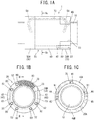
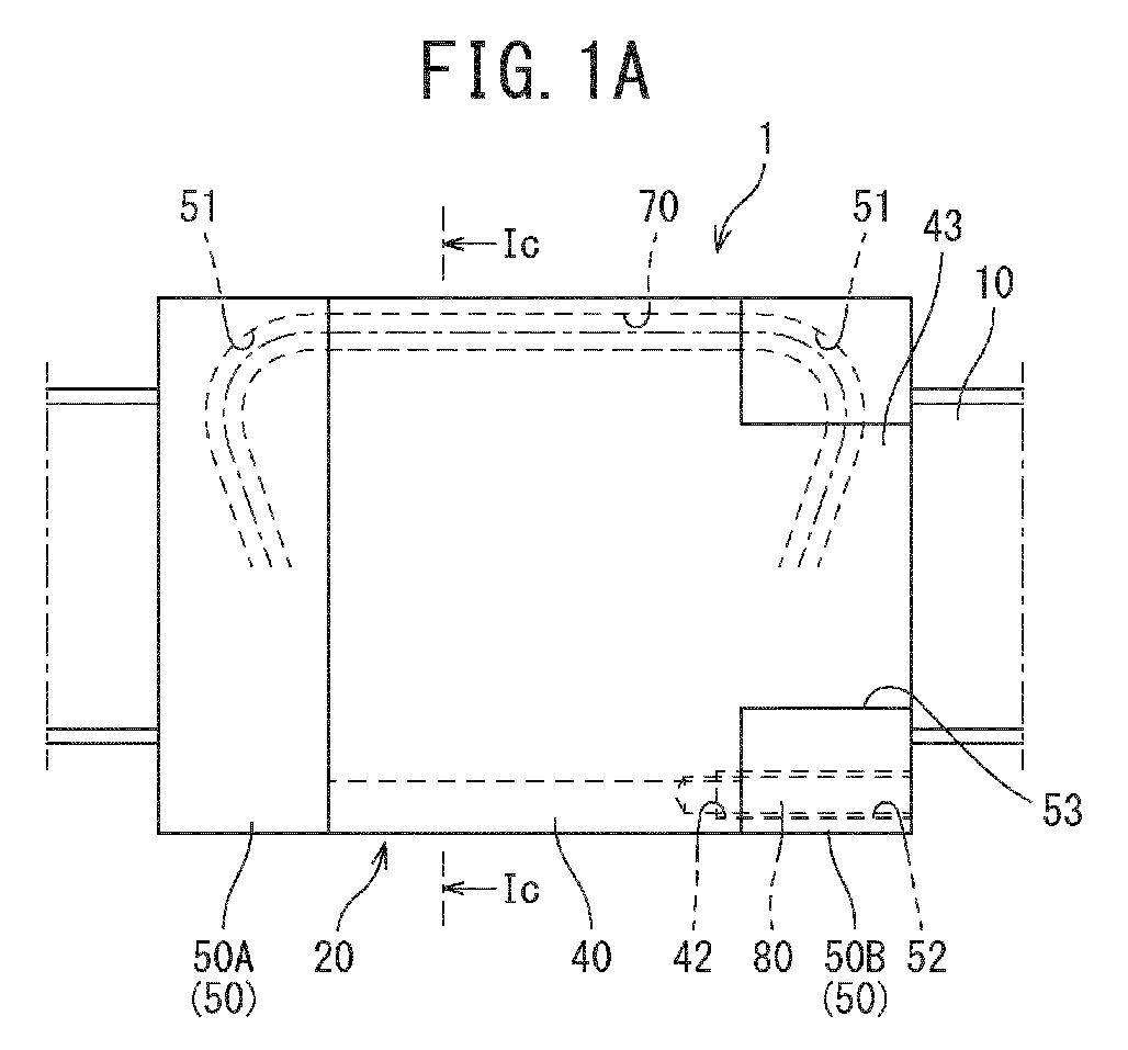
FIGS. 1A to 1C are diagrams illustrating a configuration of a ball screw according to a first embodiment, andFIG. 1A is a side view of the ball screw,FIG. 1B is a back view of the ball screw,FIG. 1C is a cross-sectional view of the ball screw illustrated inFIG. 1A along the line Ic-Ic; -
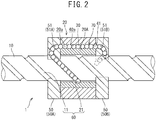
FIG. 2 is a cross-sectional view of the ball screw illustrated inFIG. 1B along the line II-II; -
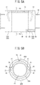
FIGS. 3A and 3B are diagrams illustrating a configuration of a ball screw according to a second embodiment, andFIG. 3A is a side view of the ball screw,FIG. 3B is a cross-sectional view of the ball screw illustrated inFIG. 3A along the line IIIb-IIIb; -
FIGS. 4A and 4B are diagrams illustrating a configuration of a ball screw according to a third embodiment, andFIG. 4A is a side view of the ball screw,FIG. 4B is a cross-sectional view of the ball screw illustrated inFIG. 4A along the line IVb-IVb; and -
FIGS. 5A and 5B are diagrams illustrating a configuration of a ball screw according to a fourth embodiment, andFIG. 5A is a side view of the ball screw,FIG. 5B is a cross-sectional view of the ball screw illustrated inFIG. 5A along the line Vb-Vb. - Embodiments of a ball screw according to the present invention will now be described with reference to the drawings.
- In the following detailed description, many particulars are described so as to provide complete understanding of the embodiments of the present invention. However, it will be obvious that one or more of the embodiments can be implemented even without those particulars. Furthermore, for simplicity of drawings, the well-known structures and devices are illustrated schematically.
- As illustrated in
FIGS. 1 and2 , aball screw 1 in a first embodiment includes ascrew shaft 10, anut 20, andballs 30 as a rolling body. - The
screw shaft 10 is a rod-like member made of steel material such as alloy steel, and has ahelical groove 11 formed on the outer peripheral surface thereof. - The
nut 20 includes anut body 20A, a coveringmember 40, and acirculation member 50. Thenut body 20A is a tubular member that is made of steel material such as alloy steel and of which the cross-section perpendicular to the shaft is formed into a barrel shape, and is arranged on the side of the outer periphery of thescrew shaft 10. On the inner peripheral surface of thenut body 20A, ahelical groove 21 facing thehelical groove 11 of thescrew shaft 10 is formed. That is, thehelical groove 11 of thescrew shaft 10 and thehelical groove 21 of thenut 20 are formed in the same lead of helix. - The
balls 30 are, for example, a spherical object made of steel material such as alloy steel, and are rollably loaded in aload rolling path 60 formed between thehelical groove 11 of thescrew shaft 10 and thehelical groove 21 of thenut 20. That is, in theball screw 1, theballs 30 roll through theload rolling path 60 in accordance with the rotational motion of thenut 20 with respect to thescrew shaft 10. Thenut 20 is configured to linearly move along an axial direction of thescrew shaft 10 through the rolling of theballs 30. - The covering member (hereinafter may be referred to as the "jacket part") 40 is made of synthetic resin or the like, and, just like the
nut body 20A, is a tubular member of which the cross-section perpendicular to the shaft is formed into a barrel shape, and is coaxially arranged on the side of the outer periphery of thenut body 20A. The diameter of the inner peripheral surface of the coveringmember 40 in an axial direction (the inner diameter of the covering member 40) is set to be greater than the diameter of the outer peripheral surface of thenut body 20A in an axial direction (the outer diameter of thenut body 20A). Then, as illustrated inFIGS. 1 and2 , on an innerperipheral surface 40a of the coveringmember 40, agroove part 41 having a cross-section that is big enough for theballs 30 to fit inside is formed along the axial direction of thescrew shaft 10; thisgroove part 41 and an outerperipheral surface 20a of thenut body 20A form a ball return path (a rolling-body return path) 70. Here, as the above-mentioned synthetic resin, polyacetal (POM) resin, polycarbonate (PC) resin, or polybutylene terephthalate (PBT) resin is used. - The
circulation member 50 has, as illustrated inFIG. 2 , a ball guidepath (a rolling-body guidepath) 51 formed inside thereof. The ball guidepath 51 is a passage communicating theload rolling path 60 with theball return path 70; theballs 30 having moved to one end of the ball guidepath 51 are scooped up from the inside of theload rolling path 60, and, from the other end, the scoopedballs 30 are returned to the inside of theload rolling path 60 through theball return path 70. - Accordingly, the
balls 30 infinitely circulate through the ball guidepath 51, theload rolling path 60, and theball return path 70 in accordance with the rotational motion of thenut 20 with respect to thescrew shaft 10. That is, the ball guidepath 51, theload rolling path 60, and theball return path 70 form an infinite circulation passage of theballs 30. - Incidentally, as illustrated in
FIGS. 1A and 1B , thecirculation member 50 is provided with a plurality of (in the present embodiment, six) throughholes 52 bored through thecirculation member 50 along the axial direction of thescrew shaft 10 in a circumferential direction of thecirculation member 50. Then, an end of the coveringmember 40 in the axial direction communicated with the throughholes 52 is also provided with screw holes 42 corresponding to the through holes 52. Therefore, by screwing a fixingmember 80, such as a bolt, into each throughhole 52 and itscorresponding screw hole 42, thecirculation member 50 is fixed to the coveringmember 40. - In this way, in the
ball screw 1 according to the present embodiment, thenut body 20A has a reduced diameter compared to conventional ones, and the coveringmember 40 is installed on the outer periphery of thenut body 20A. That is, the diameter of thenut body 20A made of steel material such as alloy steel is made smaller, and thenut body 20A is covered with the coveringmember 40 made of synthetic resin, and further, an internal circulation system is adopted. Therefore, it is possible to reduce the moment of inertia of theball screw 1 even when thenut 20 rotates at high speed. Specifically, the density of the alloy steel used in at least either thenut body 20A or theballs 30 is preferably 7 to 8 cm3/g. Furthermore, the density of the synthetic resin (POM, PC, PBT, or the like) is preferably 1.2 to 1.5 cm3/g. By defining the density of the alloy steel and the density of the synthetic resin in this way, the moment of inertia of theball screw 1 can be reduced. - Here, when the
nut 20 of the ball screw in the present embodiment rotates, the rotating force of theballs 30 in the infinite circulation passage (circuit) increases. As a result, the inertial force caused by the rotation of theballs 30 makes the coveringmember 40 more likely to rotate in a circumferential direction. Accordingly, as illustrated inFIGS. 1A and 1B , at least either one of thecirculation members 50 installed on both ends of thenut body 20A in the axial direction is provided with acutout part 53 that divides thecirculation member 50 in its circumferential direction. It is preferable to provide a pair ofcutout parts 53 in a radial direction of thenut body 20A. Then, on the coveringmember 40, anengagement part 43 engaged with thiscutout part 53 runs along the axial direction of thescrew shaft 10. That is, not only is the coveringmember 40 installed so as to cover thenut body 20A, but theengagement part 43 engaged with thecutout part 53 is provided on the coveringmember 40, thereby the coveringmember 40 can be inhibited from rotating in the circumferential direction. - Furthermore, the covering
member 40 is preferably divided into two dividedbodies engagement part 43. By configuring the coveringmember 40 like this, thenut body 20A and the circulation members 50 (50A and 50B) can be easily attached. - Incidentally, on the contact side of the divided
body 40A in contact with the dividedbody 40B, throughholes body 40A in the circumferential direction; on the contact side of the dividedbody 40B in contact with the dividedbody 40A, screw holes 45 and 45 communicated with the throughholes body 40B in the circumferential direction. - That is, the procedure of installing the covering
member 40 in the present embodiment is that, first, the dividedbodies nut body 20A and bring engagement parts 43A and 43B into contact with each other, thereby forming theengagement part 43. Then, by engaging theengagement part 43 with the cutout part 54 and screwing a fixingmember 81, such as a bolt, into the throughhole 44 and thescrew hole 45, the dividedbodies member 40. After that, the fixingmember 80, such as a bolt, is screwed into the throughhole 52 of each of thecirculation members corresponding screw hole 42 of the coveringmember 40, thereby thecirculation members member 40, and theball screw 1 is made up. - Subsequently, a second embodiment of a ball screw is described with reference to the drawings. Incidentally, in the present embodiment, the same member or part as that in the above-described first embodiment is assigned the same reference numeral, and overlapping description of the member or part is omitted. That is, the ball screw in the present embodiment has the same structure as that in the first embodiment, except that the shape of a covering member of the ball screw in the present embodiment is modified.
- As illustrated in
FIGS. 3A and 3B , in theball screw 1 according to the present embodiment, the shape of the coveringmember 40 is not "divided bodies" but an undivided cylindrical shape. - That is, the procedure of installing the covering
member 40 in the present embodiment is that, first, the coveringmember 40 is moved in the axial direction so as to cover thenut body 20A and put thenut body 20A inside, and also theengagement part 43 is engaged with thecutout part 53 of thecirculation member 50B. Then, the fixingmember 80, such as a bolt, is screwed into the throughhole 52 of thecirculation member 50B and itscorresponding screw hole 42 of the coveringmember 40, thereby thecirculation member 50B is fixed to the coveringmember 40. After that, the fixingmember 80, such as a bolt, is screwed into the throughhole 52 of thecirculation member 50A and itscorresponding screw hole 42 of the coveringmember 40, thereby thecirculation member 50A is fixed to the coveringmember 40, and theball screw 1 is made up. - In this way, the shape of the covering
member 40 is not "divided bodies" but an undivided cylindrical shape, thereby it is possible to smoothly perform the work of installing the coveringmember 40 to thenut body 20A and fixing thecirculation members member 40. - Subsequently, a third embodiment of a ball screw is described with reference to the drawings. Incidentally, in the present embodiment, the same member or part as that in the above-described first embodiment is assigned the same reference numeral, and overlapping description of the member or part is omitted. That is, the ball screw in the present embodiment has the same structure as that in the first embodiment, except that the ball screw in the present embodiment is provided with neither a cutout part nor an engagement part, and has a shape in which the covering member is engaged with the nut body.
- As illustrated in
FIGS. 4A and 4B , in theball screw 1 according to the present embodiment,cutout parts nut body 20A corresponding to the bottoms of the dividedbodies bodies cutout parts bodies bodies - In this way, the
nut body 20A is provided with thecutout parts 22, and the dividedbodies engagement parts 46 engaged with thecutout parts 22, respectively; therefore, without having to go to the trouble of a process to provide a cutout part and an engagement part, the coveringmember 40 can be fixed to thenut body 20A through the rollingbodies 30 so as not to rotate in the circumferential direction. - Subsequently, a fourth embodiment of a ball screw is described with reference to the drawings. Incidentally, in the present embodiment, the same member or part as that in the above-described first embodiment is assigned the same reference numeral, and overlapping description of the member or part is omitted. That is, the ball screw in the present embodiment has the same structure as that in the first embodiment, except that the ball screw in the present embodiment is provided with neither a cutout part nor an engagement part, and has a shape in which the covering member is engaged with the nut body, just like the third embodiment.
- As illustrated in
FIGS. 5A and 5B , in theball screw 1 according to the present embodiment,cutout parts nut body 20A corresponding to contact portions of the dividedbodies bodies cutout parts - In this way, the
nut body 20A is provided with thecutout parts 23, and the dividedbodies engagement parts 47 engaged with thecutout parts 23, respectively; therefore, without having to go to the trouble of a process to provide a cutout part and an engagement part, the coveringmember 40 can be fixed to thenut body 20A through the rollingbodies 30 so as not to rotate in the circumferential direction. - As described above, in the ball screw according to the present invention, the
nut body 20A has a reduced diameter compared to conventional ones, and the coveringmember 40 is installed on the outer periphery of thenut body 20A, and an internal circulation system is adopted; therefore, it is possible to provide a ball screw that achieves the reduction of the moment of inertia even when thenut 20 rotates at high speed and the reduction of the manufacturing cost. - The ball screw according to the present invention can be applied to, for example, a long machining center and a long conveying device. The term "long" here means, for example, an entire length of the ball screw is about forty or more times as large as the diameter of a screw shaft of the ball screw.
- Furthermore, the ball screw according to the present invention can be applied to, for example, a machine tool, such as an injection molding machine, and a conveying device. In particular, the ball screw according to the present invention is suitable to be applied to a rolling device for machine tool to which a high load is applied, such as an injection drive shaft and a clamping mechanism driving unit of an electric injection molding machine or an electric press.
- The present invention is described above with reference to the specific embodiments; however, this description is not intended to limit the invention. Various variations of the embodiments discussed here and other embodiments of the present invention will be obvious to those skilled in the art by referring to the description of the present invention. Therefore, claims should be interpreted to cover these variations or other embodiments included in the scope and gist of the present invention as well.
- For example, in the above-described embodiments, the infinite circulation passage of the balls is a one-lane passage; however, it can be configured to be a two-lane passage. Furthermore, the cutout part and the engagement part can be provided in any place of the nut body and the covering member in the circumferential direction. Moreover, the rolling bodies can be not balls but, for example, rollers.
- The present invention is described above with reference to the specific embodiments; however, this description is not intended to limit the invention. Various variations of the embodiments discussed here and other embodiments of the present invention will be obvious to those skilled in the art by referring to the description of the present invention. Therefore, claims should be interpreted to cover these variations or other embodiments included in the scope and gist of the present invention as well.
-
- 1
- ball screw
- 10
- screw shaft
- 11
- helical groove (of screw shaft)
- 20
- nut
- 20a
- outer peripheral surface (of nut)
- 20A
- nut body
- 21
- helical groove (of nut)
- 22
- cutout part
- 23
- cutout part
- 30
- rolling body (ball)
- 40
- covering member
- 40a
- inner peripheral surface (of covering member)
- 40A, 40B
- divided body
- 41
- groove part
- 42
- screw hole
- 43
- engagement part
- 44
- through hole
- 45
- screw hole
- 46
- engagement part
- 47
- engagement part
- 50
- circulation member
- 51
- ball guidepath
- 52
- through hole
- 53
- cutout part
- 60
- load rolling path
- 70
- ball return path
- 80
- fixing member
- 81
- fixing member
Claims (5)
- A ball screw comprising:a screw shaft with a helical groove formed on its outer peripheral surface;a tube-shaped nut body with a helical groove formed on its inner peripheral surface;rolling bodies configured to be placed in a load rolling path formed by the helical groove of the screw shaft and the helical groove of the nut body, a rolling-body guidepath communicated with the load rolling path, and a rolling-body return path communicated with the load rolling path and the rolling-body guidepath;circulation members configured to have the rolling-body return path formed inside and be installed on both ends of the nut body in an axial direction; anda synthetic-resin covering member configured to be shaped into a tube arranged coaxially with the nut body to cover an outer peripheral surface of the nut body, a groove part formed on its inner peripheral surface and the outer peripheral surface of the nut body forming the rolling-body return path,wherein the covering member is provided with an engagement part engaged with a cutout part formed on outer peripheral surfaces of the circulation members or the outer peripheral surface of the nut body to prevent the covering member from rotating in a circumferential direction.
- The ball screw according to claim 1, wherein the covering member is composed of a plurality of divided bodies into which the covering member is divided in the circumferential direction.
- The ball screw according to claim 1 or 2, wherein the cutout part includes a pair of cutout parts formed on the circulation members or the nut body in a radial direction.
- A machine tool including the ball screw according to any one of claims 1 to 3.
- A conveying device including the ball screw according to any one of claims 1 to 3.
Applications Claiming Priority (2)
| Application Number | Priority Date | Filing Date | Title |
|---|---|---|---|
| JP2015140705 | 2015-07-14 | ||
| PCT/JP2016/070177 WO2017010407A1 (en) | 2015-07-14 | 2016-07-07 | Ball screw, machine tool, and conveying device |
Publications (3)
| Publication Number | Publication Date |
|---|---|
| EP3324077A1 true EP3324077A1 (en) | 2018-05-23 |
| EP3324077A4 EP3324077A4 (en) | 2018-06-20 |
| EP3324077B1 EP3324077B1 (en) | 2019-09-18 |
Family
ID=57757339
Family Applications (1)
| Application Number | Title | Priority Date | Filing Date |
|---|---|---|---|
| EP16824387.1A Active EP3324077B1 (en) | 2015-07-14 | 2016-07-07 | Ball screw, machine tool, and conveying device |
Country Status (7)
| Country | Link |
|---|---|
| US (1) | US20180202525A1 (en) |
| EP (1) | EP3324077B1 (en) |
| JP (1) | JPWO2017010407A1 (en) |
| KR (1) | KR102019584B1 (en) |
| CN (1) | CN107835908A (en) |
| TW (1) | TWI600850B (en) |
| WO (1) | WO2017010407A1 (en) |
Families Citing this family (3)
| Publication number | Priority date | Publication date | Assignee | Title |
|---|---|---|---|---|
| WO2019138757A1 (en) * | 2018-01-11 | 2019-07-18 | 日立オートモティブシステムズ株式会社 | Power steering device |
| WO2023188057A1 (en) * | 2022-03-30 | 2023-10-05 | 株式会社ジェイテクト | Ball screw device |
| WO2023188058A1 (en) * | 2022-03-30 | 2023-10-05 | 株式会社ジェイテクト | Ball screw device |
Family Cites Families (18)
| Publication number | Priority date | Publication date | Assignee | Title |
|---|---|---|---|---|
| GB1574291A (en) * | 1977-08-23 | 1980-09-03 | Skf Kugellagerfabriken Gmbh | Recirculating linear rolling bearing |
| IT1245496B (en) * | 1991-01-25 | 1994-09-27 | Ricerca Elettromeccanica Srl | SCREW LINEAR ACTUATOR AND / OR BALL CIRCULATION |
| CH685513A5 (en) * | 1992-05-18 | 1995-07-31 | Eichenberger Gewinde Ag | Low=friction nut travelling along rotating threaded spindle |
| US5555770A (en) * | 1994-10-12 | 1996-09-17 | Thomson Saginaw Ball Screw Company, Inc. | Ball screw and nut system |
| JPH11344094A (en) | 1998-05-29 | 1999-12-14 | Sumitomo Heavy Ind Ltd | Ball screw for revolving nut |
| JP4331820B2 (en) * | 1999-04-30 | 2009-09-16 | Thk株式会社 | Linear motion device spacer and linear motion device using the spacer |
| JP2002226029A (en) * | 2001-01-26 | 2002-08-14 | Nsk Ltd | Work transfer device |
| DE10297160B4 (en) * | 2001-09-04 | 2015-11-19 | Thk Co., Ltd. | Ball screw |
| JP4786835B2 (en) * | 2001-09-05 | 2011-10-05 | 株式会社ジェイテクト | Ball screw device |
| TWI221512B (en) * | 2002-04-15 | 2004-10-01 | Smc Corp | Ball screw mechanism |
| DE102004063203B4 (en) * | 2004-12-23 | 2010-07-22 | Danaher Linear Gmbh | Method for producing a ball screw and ball screw |
| JP4916873B2 (en) * | 2006-12-27 | 2012-04-18 | 株式会社アイエイアイ | Ball screw / ball nut mechanism |
| CN101652224A (en) * | 2007-03-30 | 2010-02-17 | Thk株式会社 | Spindle drive mechanism for machine tool |
| JP5012832B2 (en) * | 2009-02-19 | 2012-08-29 | 日本精工株式会社 | Ball screw and ball screw device having the same |
| EP2532924B1 (en) * | 2010-03-17 | 2019-11-20 | NSK Ltd. | Ball screw, manufacturing method of nut for ball screw |
| JP5440951B2 (en) * | 2010-05-11 | 2014-03-12 | 日立金属株式会社 | Manufacturing method of flat enameled wire and flat enameled wire |
| DE102013105668B9 (en) * | 2013-06-03 | 2015-02-19 | Hiwin Technologies Corp. | Device, namely roller bearing or gear with a lubricating structure for two ring structures forming rolling body |
| JP5648727B1 (en) * | 2013-09-19 | 2015-01-07 | 日本精工株式会社 | Ball screw |
-
2016
- 2016-07-07 JP JP2017528649A patent/JPWO2017010407A1/en active Pending
- 2016-07-07 EP EP16824387.1A patent/EP3324077B1/en active Active
- 2016-07-07 KR KR1020177035607A patent/KR102019584B1/en active Active
- 2016-07-07 US US15/742,609 patent/US20180202525A1/en not_active Abandoned
- 2016-07-07 WO PCT/JP2016/070177 patent/WO2017010407A1/en not_active Ceased
- 2016-07-07 CN CN201680040951.9A patent/CN107835908A/en active Pending
- 2016-07-14 TW TW105122240A patent/TWI600850B/en not_active IP Right Cessation
Also Published As
| Publication number | Publication date |
|---|---|
| KR20180005237A (en) | 2018-01-15 |
| EP3324077A4 (en) | 2018-06-20 |
| KR102019584B1 (en) | 2019-09-06 |
| CN107835908A (en) | 2018-03-23 |
| TW201716705A (en) | 2017-05-16 |
| WO2017010407A1 (en) | 2017-01-19 |
| TWI600850B (en) | 2017-10-01 |
| JPWO2017010407A1 (en) | 2018-04-26 |
| US20180202525A1 (en) | 2018-07-19 |
| EP3324077B1 (en) | 2019-09-18 |
Similar Documents
| Publication | Publication Date | Title |
|---|---|---|
| US10677329B2 (en) | Electromechanical actuator cylinder | |
| TWI644038B (en) | Actuator | |
| EP3324077B1 (en) | Ball screw, machine tool, and conveying device | |
| KR20100023763A (en) | Ball screw mechanism | |
| US20150047444A1 (en) | Motor driven linear actuator and electric motor thereof | |
| CN203272651U (en) | Lead screw shaft and ball screw | |
| EP3018385B1 (en) | Ball screw | |
| US11060565B2 (en) | Screw nut | |
| JPWO1998038072A1 (en) | Power steering device | |
| EP2233789A1 (en) | Ball screw device | |
| JP2017075699A (en) | Torque-transmittable linear bush | |
| JP7124301B2 (en) | Four-point contact ball bearing and ball screw device provided with the same | |
| US11493092B2 (en) | Speed-reducing or -increasing apparatus | |
| KR20190067858A (en) | Ball screw | |
| KR101462782B1 (en) | Transmission element having a lubricating structure of the rolling bodies are two annularly arranged at a distance | |
| JP7000848B2 (en) | Linear actuator | |
| CN107605951B (en) | High-precision bearing and process method thereof | |
| JP5521798B2 (en) | Ball screw device | |
| KR102110595B1 (en) | Ball Screw Unit | |
| JP5961925B2 (en) | Ball screw device and manufacturing method thereof | |
| JP6631013B2 (en) | Ball screw | |
| JP2012002309A (en) | Ball screw with ball spline | |
| RU2705637C1 (en) | Missile steering gear unit | |
| JP2005249036A (en) | Ball screw device | |
| WO2016078687A1 (en) | Screw nut assembly |
Legal Events
| Date | Code | Title | Description |
|---|---|---|---|
| STAA | Information on the status of an ep patent application or granted ep patent |
Free format text: STATUS: THE INTERNATIONAL PUBLICATION HAS BEEN MADE |
|
| PUAI | Public reference made under article 153(3) epc to a published international application that has entered the european phase |
Free format text: ORIGINAL CODE: 0009012 |
|
| STAA | Information on the status of an ep patent application or granted ep patent |
Free format text: STATUS: REQUEST FOR EXAMINATION WAS MADE |
|
| 17P | Request for examination filed |
Effective date: 20180111 |
|
| AK | Designated contracting states |
Kind code of ref document: A1 Designated state(s): AL AT BE BG CH CY CZ DE DK EE ES FI FR GB GR HR HU IE IS IT LI LT LU LV MC MK MT NL NO PL PT RO RS SE SI SK SM TR |
|
| AX | Request for extension of the european patent |
Extension state: BA ME |
|
| A4 | Supplementary search report drawn up and despatched |
Effective date: 20180524 |
|
| RIC1 | Information provided on ipc code assigned before grant |
Ipc: F16H 25/24 20060101ALI20180517BHEP Ipc: F16H 25/22 20060101AFI20180517BHEP |
|
| DAV | Request for validation of the european patent (deleted) | ||
| DAX | Request for extension of the european patent (deleted) | ||
| GRAP | Despatch of communication of intention to grant a patent |
Free format text: ORIGINAL CODE: EPIDOSNIGR1 |
|
| STAA | Information on the status of an ep patent application or granted ep patent |
Free format text: STATUS: GRANT OF PATENT IS INTENDED |
|
| RIC1 | Information provided on ipc code assigned before grant |
Ipc: F16H 25/24 20060101ALI20190401BHEP Ipc: F16H 25/22 20060101AFI20190401BHEP |
|
| INTG | Intention to grant announced |
Effective date: 20190425 |
|
| GRAS | Grant fee paid |
Free format text: ORIGINAL CODE: EPIDOSNIGR3 |
|
| GRAA | (expected) grant |
Free format text: ORIGINAL CODE: 0009210 |
|
| STAA | Information on the status of an ep patent application or granted ep patent |
Free format text: STATUS: THE PATENT HAS BEEN GRANTED |
|
| AK | Designated contracting states |
Kind code of ref document: B1 Designated state(s): AL AT BE BG CH CY CZ DE DK EE ES FI FR GB GR HR HU IE IS IT LI LT LU LV MC MK MT NL NO PL PT RO RS SE SI SK SM TR |
|
| REG | Reference to a national code |
Ref country code: GB Ref legal event code: FG4D |
|
| REG | Reference to a national code |
Ref country code: CH Ref legal event code: EP |
|
| REG | Reference to a national code |
Ref country code: DE Ref legal event code: R096 Ref document number: 602016021042 Country of ref document: DE |
|
| REG | Reference to a national code |
Ref country code: AT Ref legal event code: REF Ref document number: 1181699 Country of ref document: AT Kind code of ref document: T Effective date: 20191015 |
|
| REG | Reference to a national code |
Ref country code: IE Ref legal event code: FG4D |
|
| REG | Reference to a national code |
Ref country code: NL Ref legal event code: MP Effective date: 20190918 |
|
| PG25 | Lapsed in a contracting state [announced via postgrant information from national office to epo] |
Ref country code: FI Free format text: LAPSE BECAUSE OF FAILURE TO SUBMIT A TRANSLATION OF THE DESCRIPTION OR TO PAY THE FEE WITHIN THE PRESCRIBED TIME-LIMIT Effective date: 20190918 Ref country code: HR Free format text: LAPSE BECAUSE OF FAILURE TO SUBMIT A TRANSLATION OF THE DESCRIPTION OR TO PAY THE FEE WITHIN THE PRESCRIBED TIME-LIMIT Effective date: 20190918 Ref country code: SE Free format text: LAPSE BECAUSE OF FAILURE TO SUBMIT A TRANSLATION OF THE DESCRIPTION OR TO PAY THE FEE WITHIN THE PRESCRIBED TIME-LIMIT Effective date: 20190918 Ref country code: BG Free format text: LAPSE BECAUSE OF FAILURE TO SUBMIT A TRANSLATION OF THE DESCRIPTION OR TO PAY THE FEE WITHIN THE PRESCRIBED TIME-LIMIT Effective date: 20191218 Ref country code: LT Free format text: LAPSE BECAUSE OF FAILURE TO SUBMIT A TRANSLATION OF THE DESCRIPTION OR TO PAY THE FEE WITHIN THE PRESCRIBED TIME-LIMIT Effective date: 20190918 Ref country code: NO Free format text: LAPSE BECAUSE OF FAILURE TO SUBMIT A TRANSLATION OF THE DESCRIPTION OR TO PAY THE FEE WITHIN THE PRESCRIBED TIME-LIMIT Effective date: 20191218 |
|
| REG | Reference to a national code |
Ref country code: LT Ref legal event code: MG4D |
|
| PG25 | Lapsed in a contracting state [announced via postgrant information from national office to epo] |
Ref country code: LV Free format text: LAPSE BECAUSE OF FAILURE TO SUBMIT A TRANSLATION OF THE DESCRIPTION OR TO PAY THE FEE WITHIN THE PRESCRIBED TIME-LIMIT Effective date: 20190918 Ref country code: AL Free format text: LAPSE BECAUSE OF FAILURE TO SUBMIT A TRANSLATION OF THE DESCRIPTION OR TO PAY THE FEE WITHIN THE PRESCRIBED TIME-LIMIT Effective date: 20190918 Ref country code: RS Free format text: LAPSE BECAUSE OF FAILURE TO SUBMIT A TRANSLATION OF THE DESCRIPTION OR TO PAY THE FEE WITHIN THE PRESCRIBED TIME-LIMIT Effective date: 20190918 Ref country code: GR Free format text: LAPSE BECAUSE OF FAILURE TO SUBMIT A TRANSLATION OF THE DESCRIPTION OR TO PAY THE FEE WITHIN THE PRESCRIBED TIME-LIMIT Effective date: 20191219 |
|
| REG | Reference to a national code |
Ref country code: AT Ref legal event code: MK05 Ref document number: 1181699 Country of ref document: AT Kind code of ref document: T Effective date: 20190918 |
|
| PG25 | Lapsed in a contracting state [announced via postgrant information from national office to epo] |
Ref country code: IT Free format text: LAPSE BECAUSE OF FAILURE TO SUBMIT A TRANSLATION OF THE DESCRIPTION OR TO PAY THE FEE WITHIN THE PRESCRIBED TIME-LIMIT Effective date: 20190918 Ref country code: EE Free format text: LAPSE BECAUSE OF FAILURE TO SUBMIT A TRANSLATION OF THE DESCRIPTION OR TO PAY THE FEE WITHIN THE PRESCRIBED TIME-LIMIT Effective date: 20190918 Ref country code: PL Free format text: LAPSE BECAUSE OF FAILURE TO SUBMIT A TRANSLATION OF THE DESCRIPTION OR TO PAY THE FEE WITHIN THE PRESCRIBED TIME-LIMIT Effective date: 20190918 Ref country code: RO Free format text: LAPSE BECAUSE OF FAILURE TO SUBMIT A TRANSLATION OF THE DESCRIPTION OR TO PAY THE FEE WITHIN THE PRESCRIBED TIME-LIMIT Effective date: 20190918 Ref country code: NL Free format text: LAPSE BECAUSE OF FAILURE TO SUBMIT A TRANSLATION OF THE DESCRIPTION OR TO PAY THE FEE WITHIN THE PRESCRIBED TIME-LIMIT Effective date: 20190918 Ref country code: ES Free format text: LAPSE BECAUSE OF FAILURE TO SUBMIT A TRANSLATION OF THE DESCRIPTION OR TO PAY THE FEE WITHIN THE PRESCRIBED TIME-LIMIT Effective date: 20190918 Ref country code: AT Free format text: LAPSE BECAUSE OF FAILURE TO SUBMIT A TRANSLATION OF THE DESCRIPTION OR TO PAY THE FEE WITHIN THE PRESCRIBED TIME-LIMIT Effective date: 20190918 Ref country code: PT Free format text: LAPSE BECAUSE OF FAILURE TO SUBMIT A TRANSLATION OF THE DESCRIPTION OR TO PAY THE FEE WITHIN THE PRESCRIBED TIME-LIMIT Effective date: 20200120 |
|
| PG25 | Lapsed in a contracting state [announced via postgrant information from national office to epo] |
Ref country code: CZ Free format text: LAPSE BECAUSE OF FAILURE TO SUBMIT A TRANSLATION OF THE DESCRIPTION OR TO PAY THE FEE WITHIN THE PRESCRIBED TIME-LIMIT Effective date: 20190918 Ref country code: SK Free format text: LAPSE BECAUSE OF FAILURE TO SUBMIT A TRANSLATION OF THE DESCRIPTION OR TO PAY THE FEE WITHIN THE PRESCRIBED TIME-LIMIT Effective date: 20190918 Ref country code: SM Free format text: LAPSE BECAUSE OF FAILURE TO SUBMIT A TRANSLATION OF THE DESCRIPTION OR TO PAY THE FEE WITHIN THE PRESCRIBED TIME-LIMIT Effective date: 20190918 Ref country code: IS Free format text: LAPSE BECAUSE OF FAILURE TO SUBMIT A TRANSLATION OF THE DESCRIPTION OR TO PAY THE FEE WITHIN THE PRESCRIBED TIME-LIMIT Effective date: 20200224 |
|
| REG | Reference to a national code |
Ref country code: DE Ref legal event code: R097 Ref document number: 602016021042 Country of ref document: DE |
|
| PLBE | No opposition filed within time limit |
Free format text: ORIGINAL CODE: 0009261 |
|
| STAA | Information on the status of an ep patent application or granted ep patent |
Free format text: STATUS: NO OPPOSITION FILED WITHIN TIME LIMIT |
|
| PG2D | Information on lapse in contracting state deleted |
Ref country code: IS |
|
| PG25 | Lapsed in a contracting state [announced via postgrant information from national office to epo] |
Ref country code: DK Free format text: LAPSE BECAUSE OF FAILURE TO SUBMIT A TRANSLATION OF THE DESCRIPTION OR TO PAY THE FEE WITHIN THE PRESCRIBED TIME-LIMIT Effective date: 20190918 Ref country code: IS Free format text: LAPSE BECAUSE OF FAILURE TO SUBMIT A TRANSLATION OF THE DESCRIPTION OR TO PAY THE FEE WITHIN THE PRESCRIBED TIME-LIMIT Effective date: 20200119 |
|
| 26N | No opposition filed |
Effective date: 20200619 |
|
| PG25 | Lapsed in a contracting state [announced via postgrant information from national office to epo] |
Ref country code: SI Free format text: LAPSE BECAUSE OF FAILURE TO SUBMIT A TRANSLATION OF THE DESCRIPTION OR TO PAY THE FEE WITHIN THE PRESCRIBED TIME-LIMIT Effective date: 20190918 |
|
| REG | Reference to a national code |
Ref country code: DE Ref legal event code: R119 Ref document number: 602016021042 Country of ref document: DE |
|
| PG25 | Lapsed in a contracting state [announced via postgrant information from national office to epo] |
Ref country code: MC Free format text: LAPSE BECAUSE OF FAILURE TO SUBMIT A TRANSLATION OF THE DESCRIPTION OR TO PAY THE FEE WITHIN THE PRESCRIBED TIME-LIMIT Effective date: 20190918 |
|
| REG | Reference to a national code |
Ref country code: CH Ref legal event code: PL |
|
| GBPC | Gb: european patent ceased through non-payment of renewal fee |
Effective date: 20200707 |
|
| REG | Reference to a national code |
Ref country code: BE Ref legal event code: MM Effective date: 20200731 |
|
| PG25 | Lapsed in a contracting state [announced via postgrant information from national office to epo] |
Ref country code: FR Free format text: LAPSE BECAUSE OF NON-PAYMENT OF DUE FEES Effective date: 20200731 Ref country code: GB Free format text: LAPSE BECAUSE OF NON-PAYMENT OF DUE FEES Effective date: 20200707 Ref country code: IE Free format text: LAPSE BECAUSE OF NON-PAYMENT OF DUE FEES Effective date: 20200707 Ref country code: CH Free format text: LAPSE BECAUSE OF NON-PAYMENT OF DUE FEES Effective date: 20200731 Ref country code: LU Free format text: LAPSE BECAUSE OF NON-PAYMENT OF DUE FEES Effective date: 20200707 Ref country code: LI Free format text: LAPSE BECAUSE OF NON-PAYMENT OF DUE FEES Effective date: 20200731 |
|
| PG25 | Lapsed in a contracting state [announced via postgrant information from national office to epo] |
Ref country code: DE Free format text: LAPSE BECAUSE OF NON-PAYMENT OF DUE FEES Effective date: 20210202 Ref country code: BE Free format text: LAPSE BECAUSE OF NON-PAYMENT OF DUE FEES Effective date: 20200731 |
|
| PG25 | Lapsed in a contracting state [announced via postgrant information from national office to epo] |
Ref country code: TR Free format text: LAPSE BECAUSE OF FAILURE TO SUBMIT A TRANSLATION OF THE DESCRIPTION OR TO PAY THE FEE WITHIN THE PRESCRIBED TIME-LIMIT Effective date: 20190918 Ref country code: MT Free format text: LAPSE BECAUSE OF FAILURE TO SUBMIT A TRANSLATION OF THE DESCRIPTION OR TO PAY THE FEE WITHIN THE PRESCRIBED TIME-LIMIT Effective date: 20190918 Ref country code: CY Free format text: LAPSE BECAUSE OF FAILURE TO SUBMIT A TRANSLATION OF THE DESCRIPTION OR TO PAY THE FEE WITHIN THE PRESCRIBED TIME-LIMIT Effective date: 20190918 |
|
| PG25 | Lapsed in a contracting state [announced via postgrant information from national office to epo] |
Ref country code: MK Free format text: LAPSE BECAUSE OF FAILURE TO SUBMIT A TRANSLATION OF THE DESCRIPTION OR TO PAY THE FEE WITHIN THE PRESCRIBED TIME-LIMIT Effective date: 20190918 |