EP3324036A1 - Engine control device - Google Patents
Engine control device Download PDFInfo
- Publication number
- EP3324036A1 EP3324036A1 EP16824290.7A EP16824290A EP3324036A1 EP 3324036 A1 EP3324036 A1 EP 3324036A1 EP 16824290 A EP16824290 A EP 16824290A EP 3324036 A1 EP3324036 A1 EP 3324036A1
- Authority
- EP
- European Patent Office
- Prior art keywords
- ignition
- energy supply
- supply units
- ignition energy
- coil
- Prior art date
- Legal status (The legal status is an assumption and is not a legal conclusion. Google has not performed a legal analysis and makes no representation as to the accuracy of the status listed.)
- Granted
Links
Images


Classifications
-
- F—MECHANICAL ENGINEERING; LIGHTING; HEATING; WEAPONS; BLASTING
- F02—COMBUSTION ENGINES; HOT-GAS OR COMBUSTION-PRODUCT ENGINE PLANTS
- F02P—IGNITION, OTHER THAN COMPRESSION IGNITION, FOR INTERNAL-COMBUSTION ENGINES; TESTING OF IGNITION TIMING IN COMPRESSION-IGNITION ENGINES
- F02P3/00—Other installations
- F02P3/02—Other installations having inductive energy storage, e.g. arrangements of induction coils
- F02P3/04—Layout of circuits
- F02P3/0407—Opening or closing the primary coil circuit with electronic switching means
- F02P3/0435—Opening or closing the primary coil circuit with electronic switching means with semiconductor devices
- F02P3/0442—Opening or closing the primary coil circuit with electronic switching means with semiconductor devices using digital techniques
-
- F—MECHANICAL ENGINEERING; LIGHTING; HEATING; WEAPONS; BLASTING
- F02—COMBUSTION ENGINES; HOT-GAS OR COMBUSTION-PRODUCT ENGINE PLANTS
- F02P—IGNITION, OTHER THAN COMPRESSION IGNITION, FOR INTERNAL-COMBUSTION ENGINES; TESTING OF IGNITION TIMING IN COMPRESSION-IGNITION ENGINES
- F02P3/00—Other installations
- F02P3/02—Other installations having inductive energy storage, e.g. arrangements of induction coils
- F02P3/04—Layout of circuits
- F02P3/05—Layout of circuits for control of the magnitude of the current in the ignition coil
-
- F—MECHANICAL ENGINEERING; LIGHTING; HEATING; WEAPONS; BLASTING
- F02—COMBUSTION ENGINES; HOT-GAS OR COMBUSTION-PRODUCT ENGINE PLANTS
- F02P—IGNITION, OTHER THAN COMPRESSION IGNITION, FOR INTERNAL-COMBUSTION ENGINES; TESTING OF IGNITION TIMING IN COMPRESSION-IGNITION ENGINES
- F02P15/00—Electric spark ignition having characteristics not provided for in, or of interest apart from, groups F02P1/00 - F02P13/00 and combined with layout of ignition circuits
- F02P15/02—Arrangements having two or more sparking plugs
-
- F—MECHANICAL ENGINEERING; LIGHTING; HEATING; WEAPONS; BLASTING
- F02—COMBUSTION ENGINES; HOT-GAS OR COMBUSTION-PRODUCT ENGINE PLANTS
- F02P—IGNITION, OTHER THAN COMPRESSION IGNITION, FOR INTERNAL-COMBUSTION ENGINES; TESTING OF IGNITION TIMING IN COMPRESSION-IGNITION ENGINES
- F02P15/00—Electric spark ignition having characteristics not provided for in, or of interest apart from, groups F02P1/00 - F02P13/00 and combined with layout of ignition circuits
- F02P15/10—Electric spark ignition having characteristics not provided for in, or of interest apart from, groups F02P1/00 - F02P13/00 and combined with layout of ignition circuits having continuous electric sparks
-
- F—MECHANICAL ENGINEERING; LIGHTING; HEATING; WEAPONS; BLASTING
- F02—COMBUSTION ENGINES; HOT-GAS OR COMBUSTION-PRODUCT ENGINE PLANTS
- F02P—IGNITION, OTHER THAN COMPRESSION IGNITION, FOR INTERNAL-COMBUSTION ENGINES; TESTING OF IGNITION TIMING IN COMPRESSION-IGNITION ENGINES
- F02P17/00—Testing of ignition installations, e.g. in combination with adjusting; Testing of ignition timing in compression-ignition engines
- F02P17/12—Testing characteristics of the spark, ignition voltage or current
-
- F—MECHANICAL ENGINEERING; LIGHTING; HEATING; WEAPONS; BLASTING
- F02—COMBUSTION ENGINES; HOT-GAS OR COMBUSTION-PRODUCT ENGINE PLANTS
- F02P—IGNITION, OTHER THAN COMPRESSION IGNITION, FOR INTERNAL-COMBUSTION ENGINES; TESTING OF IGNITION TIMING IN COMPRESSION-IGNITION ENGINES
- F02P3/00—Other installations
-
- F—MECHANICAL ENGINEERING; LIGHTING; HEATING; WEAPONS; BLASTING
- F02—COMBUSTION ENGINES; HOT-GAS OR COMBUSTION-PRODUCT ENGINE PLANTS
- F02P—IGNITION, OTHER THAN COMPRESSION IGNITION, FOR INTERNAL-COMBUSTION ENGINES; TESTING OF IGNITION TIMING IN COMPRESSION-IGNITION ENGINES
- F02P5/00—Advancing or retarding ignition; Control therefor
- F02P5/04—Advancing or retarding ignition; Control therefor automatically, as a function of the working conditions of the engine or vehicle or of the atmospheric conditions
- F02P5/145—Advancing or retarding ignition; Control therefor automatically, as a function of the working conditions of the engine or vehicle or of the atmospheric conditions using electrical means
- F02P5/15—Digital data processing
- F02P5/1502—Digital data processing using one central computing unit
- F02P5/1516—Digital data processing using one central computing unit with means relating to exhaust gas recirculation, e.g. turbo
-
- F—MECHANICAL ENGINEERING; LIGHTING; HEATING; WEAPONS; BLASTING
- F02—COMBUSTION ENGINES; HOT-GAS OR COMBUSTION-PRODUCT ENGINE PLANTS
- F02P—IGNITION, OTHER THAN COMPRESSION IGNITION, FOR INTERNAL-COMBUSTION ENGINES; TESTING OF IGNITION TIMING IN COMPRESSION-IGNITION ENGINES
- F02P9/00—Electric spark ignition control, not otherwise provided for
- F02P9/002—Control of spark intensity, intensifying, lengthening, suppression
- F02P9/007—Control of spark intensity, intensifying, lengthening, suppression by supplementary electrical discharge in the pre-ionised electrode interspace of the sparking plug, e.g. plasma jet ignition
-
- Y—GENERAL TAGGING OF NEW TECHNOLOGICAL DEVELOPMENTS; GENERAL TAGGING OF CROSS-SECTIONAL TECHNOLOGIES SPANNING OVER SEVERAL SECTIONS OF THE IPC; TECHNICAL SUBJECTS COVERED BY FORMER USPC CROSS-REFERENCE ART COLLECTIONS [XRACs] AND DIGESTS
- Y02—TECHNOLOGIES OR APPLICATIONS FOR MITIGATION OR ADAPTATION AGAINST CLIMATE CHANGE
- Y02T—CLIMATE CHANGE MITIGATION TECHNOLOGIES RELATED TO TRANSPORTATION
- Y02T10/00—Road transport of goods or passengers
- Y02T10/10—Internal combustion engine [ICE] based vehicles
- Y02T10/40—Engine management systems
Definitions
- the present invention relates to an engine control device which performs an ignition control to overlap spark discharges from an ignition plug of an internal combustion engine.
- a state of the air-fuel mixture deviates in the vicinity of the ignition plug so as to cause a state where the air-fuel ratio is reduced or a state where an inert gas such as an EGR gas is mixed.
- an unstable ignitionability of the air-fuel mixture is improved in a short-term discharge and the fuel efficiency of the internal combustion engine is improved by improving the ignitionability and by making the combustion stable.
- PTL 1 Ignition device of overlap discharge type for internal combustion engine
- a predetermined voltage for example, 500 V
- the boosting circuit is necessarily configured to handle the cylinders.
- the ignition energy is supplied by two systems of the boosting circuit which is provided in the ignition plug separately from the ignition coil.
- an ignition system equipped with ignition energy supply units of the two systems may cause the same problem regardless of the ignition coil and the boosting circuit.
- the invention has been made to solve such a problem, and an object thereof is to provide an engine control device which can suppress a shortage of output terminals of the control unit and an increase of costs even in a multiple-cylinder internal combustion engine equipped with the ignition energy supply units of two systems.
- an engine control device which controls a multiple-cylinder engine in which ignition energy supply units of two systems are provided for every cylinder, wherein a signal is transmitted through a common signal line to a plurality of ignition energy supply units of one system among the ignition energy supply units of the two systems to control the ignition energy supply units of the one system.
- an ignition device for an internal combustion engine of the invention there is provided an ignition system equipped with ignition energy supply units of two systems for every cylinder.
- the ignition energy supply units of the two systems can be controlled only by adding one signal line with respect to the ignition system equipped only with the ignition energy supply units of one system. It is possible to provide an engine control device which can suppress a shortage of output terminals of the control unit and an increase of costs even in a multiple-cylinder internal combustion engine.
- FIGS. 1 to 11 a first configuration of a control system of an internal combustion engine to which the invention is applied.
- the embodiment illustrated in FIG. 1 is a 4-cylinder internal combustion engine of a so-called port injection type, and an engine of a cylinder direct injection type may be applied regardless of the number of cylinders.
- FIG. 1 is a diagram illustrating a configuration of the internal combustion engine control system according to the first configuration.
- the air sucked into an internal combustion engine 65 passes through an air cleaner 60, and is introduced to an air flow sensor 2 of a hot wire type.
- a hot-wire air flow sensor is used in the air flow sensor 2 of the hot wire type.
- a signal corresponding to an intake air amount is output from the air flow sensor 2 of the hot wire type, and an intake air temperature signal is output measured by the intake air temperature sensor 2 using a thermistor.
- the intake air passes through a connected duct 61 and a throttle valve 40 which controls an air flow rate, and enters a collector 62.
- the throttle valve is operated by a throttle drive motor 42 which is driven by a control unit 71.
- the air entered the collector 62 is distributed into intake pipes connected to the engine, and sucked into the cylinder.
- a valve timing variation mechanism is equipped in a valve drive system to perform a feedback control to adjust the valve to be a target angle.
- a crank angle sensor 7 attached to a cylinder block outputs a pulse at every predetermined crank angle, and the output is input to the control unit 71.
- a fuel is sucked and compressed by a fuel pump 20 from a fuel tank 21, adjusted in pressure to be a certain pressure by a pressure regulator 22, and injected from an injector 23 provided in the intake pipe into the intake pipe.
- a throttle sensor 1 is attached to the throttle valve 40 to detect an opening of the throttle valve.
- a signal of the sensor is input to the control unit 71 to perform a feedback control of the opening of the throttle valve 40 and to detect a complete close position and an acceleration. Further, a target opening of the feedback control is obtained from a driver's stepping amount detected by an accelerator opening sensor 14 and an amount of an idle rotation speed control (that is, ISC control).
- a water temperature sensor 3 is attached to the internal combustion engine 65 to detect a coolant temperature.
- a signal of the sensor is input to the control unit 71 to detect a warming-up state of the internal combustion engine 65, and a target rotation speed is set at the time of increasing a fuel injection amount, correcting an ignition timing, turning on/off a radiator fan 75, and an idle operation.
- an air condition switch 18 which monitors a state of an air-conditioning clutch and a neutral switch 17 which is built in a transmission to monitor a state of a drive system are attached to calculate a target rotation speed at an idle time and a load correction amount.
- An air-fuel ratio sensor 8 is mounted in an exhaust pipe of the engine, and outputs a signal according to an oxygen concentration in the exhaust gas.
- the signal is input to the control unit 71, and used to adjust a pulse width of a fuel injection to be a target air-fuel ratio required according to an operation situation.
- An ignition coil 30 is provided with two coils (a main coil and a sub coil), each of which is connected to the control unit 71.
- An ignition signal and a timing signal are input according to an energizing time and an ignition timing of each coil which are calculated by the control unit 71.
- the discharging caused by the main coil and the discharging caused by the sub coil are overlapped to be output, and a spark discharge of an ignition plug 33 occurs.
- the control unit 71 is configured by a CPU 78 and a power source IC 79 as illustrated in FIG. 2 .
- the signals input to the control unit 71 organized using this drawing there are input signals from the air flow sensor, the built-in intake air temperature sensor 2, the crank angle sensor 7, the throttle sensor 1, the water temperature sensor 3, an oil temperature sensor 25, and the accelerator opening sensor 14.
- the output signal from the control unit 71 is output to the injector 23, a fuel pump 20, the ignition coil (main) 30, a timing signal 110, and the throttle drive motor 42.
- the timing signal 110 is configured to receive the output signal and to monitor an output result.
- FIG. 3 illustrates a configuration of an engine control device according to this embodiment in which the 4-cylinder internal combustion engine is exemplified.
- main ignition signals 101a to 101d for cylinders are output from a main ignition signal generation unit 1000 mounted in the control unit 71, and signal lines for transmitting the respective signals are connected to coils 30a to 30d provided in the respective cylinders.
- the coil 30a is provided with two coils of an ignition coil (main) 30a-1 and an ignition coil (sub) 30a-2 therein, and the ignition coil (main) 30a-1 and the ignition coil (sub) 30a-2 are connected to an overlapping discharge line 203a in series.
- a signal line for transmitting the ignition signal 101a output from the control unit 71 is connected to the ignition coil (main) 30a-1 and the ignition coil (sub) 30a-2.
- the timing signal 110 is output from a timing signal generation unit 1100 mounted in the control unit 71 through one common signal line.
- One side of the common signal line for transmitting the timing signal 110 is connected to the control unit 71, and the other side is branched in the middle thereof.
- the branched signal lines are connected to the ignition coils (sub) 30a-2 to 30d-2 which are disposed on a side near the control unit with respect to the ignition coil (main).
- the timing signal transmitted from the control unit 71 is input to the ignition coils (sub) 30a-2 to 30d-2, and the outputs of the ignition coils (sub) 30a-2 to 30d-2 are input to the ignition coils (main) 30a-1 to 30d-1.
- the ignition coil (main) 30a-1 and the ignition coil (sub) 30a-2 are illustrated by one coil 30a, and the ignition coil (main) 30a-1 and the ignition coil (sub) 30a-2 may be separately and independently configured without using the coil 30a.
- control unit of this embodiment transmits the timing signal to a plurality of ignition energy supply units of one system (that is, a plurality of ignition coils (sub)) through a common signal line (one signal line) among ignition energy supply units of two systems illustrated by the ignition coils (main) and the ignition coils (sub) so as to control the ignition energy supply units (a plurality of ignition coils (sub)) of one system.
- a timing signal monitor unit 1200 is provided in the control unit 71 to monitor the operation of the timing signal 110, and detects an abnormality of the ignition coil (sub) by monitoring the operation of the timing signal. Specifically, in a case where an abnormality occurs in the ignition coil (sub), the timing signal 110 is pulled up or down in the ignition coil (sub) to fix the potential. Therefore, the timing signal monitor value detected by the timing signal monitor unit 1200 is fixed even when the timing signal 110 is commanded by the control unit 71, so that the control unit 71 can determine control and abnormality from a difference between the command of the timing signal 110 and a monitor value.
- control unit of this embodiment receives the timing signal through the command signal line (one signal line) from the plurality of ignition energy supply units of one system (that is, the plurality of ignition coils (sub)) among the ignition energy supply units of two systems illustrated by the ignition coil (main) and the ignition coil (sub) so as to detect an abnormality of the plurality of ignition energy supply units (the plurality of ignition coils (sub)) of one system.
- FIG. 4 is a diagram illustrating a detailed connection between the ignition coil (main) 30a-1 and the ignition coil (sub) 30a-2.
- the ignition coil (main) 30a-1 is configured by an ignitor, a primary coil, and a secondary coil.
- the main ignition signal 101a output from the control unit 71 is input to the ignitor, and the current of the primary coil is controlled by the main ignition signal 101a, so that the ignition of the ignition plug 33 is performed.
- the ignition coil (sub) 30a-2 is configured by an ignitor, a primary coil, a secondary coil, and a control circuit.
- the control circuit receives the main ignition signal 101a which is an ignition signal of the ignition energy supply units of the other side belonging to the same cylinder as that of the ignition coil (sub) 30a-2 and the timing signal 110. At this time, the control circuit determines whether the cylinder is an ignition cylinder using the ignition signal of the ignition energy supply units of the other side, and generates a sub ignition signal with respect to the ignition coil (sub) 30a-2 according to the energizing time commanded by the timing signal.
- the current generated in the secondary coil is controlled by controlling the current of the primary coil using the sub ignition signal output from the control circuit.
- the upstream side of the secondary coil of the ignition coil (sub) 30a-2 is connected to the downstream side of the secondary coil of the ignition coil (main) 30a-1, and the secondary coil of the ignition coil (main) 30a-1 and the secondary coil of the ignition coil (sub) 30a-2 are connected in series with respect to the ignition plug 33.
- FIG. 5 is a timing chart illustrating input/output waveforms of the coil 30 configured as illustrated in FIG. 4 .
- a transistor in an ignitor 301a-1 is switched at an ON timing of a rising edge of a rectangular waveform of the main ignition signal 101a, and a magnetic energy is accumulated in the ignition coil (main) 30a-1 by a primary current in a range from 5 to 10 A flowing on the primary side of the ignition coil (main) 30a-1.
- the transistor in the ignitor 301a-1 is switched at an OFF timing (so-called ignition timing) of a falling edge of a rectangular waveform of the main ignition signal 101, and the primary current is blocked.
- a high secondary voltage is generated on the secondary side of the ignition coil (main) 30a-1, and thus the discharge starts in the ignition plug 33.
- the secondary voltage causing the discharge is typically about 10 kV to 15 kV, and the secondary current caused by the discharge is within a range of 0.1 A for example. Then, the discharge caused by the energy emission goes on several ms.
- the sub ignition signal is turned on by the control circuit, a transistor in an ignitor 301a-2 is switched at a timing when the sub ignition signal is turned on, and a primary current in a range of 5 to 10 A flows to the primary side of the ignition coil (sub) 30a-2.
- the sub ignition signal is turned off at a timing when the timing signal 110 is turned off, the transistor in the ignitor 301a-2 is switched, the primary current is blocked, a high secondary voltage (not illustrated) is generated on the secondary side of the ignition coil (sub) 30a-2, and the discharge is overlapped in the ignition plug 33.
- the OFF timing of the falling edge of the timing signal 110 is set to be the same as the OFF timing of the main ignition signal 101a, or to be delayed by a phase difference ⁇ IGN [ms], so that the discharge time can be extended compared to a case where only the ignition coil (main) 30a-1 is used for the ignition.
- control circuit has a function of monitoring the ignition coil (sub) 30a-2, and can detect an abnormality of the ignition coil (sub) 30a-2.
- the timing signal 110 is electrically fixed to either LOW (0 V) or HIGH (5 V) in the control circuit, and the ignition coil (sub) is monitored by the control unit 71, so that an abnormality can be detected by the control unit 71.
- control circuit which outputs the sub ignition signal is provided in the ignition coil (sub) 30a-2, and may be provided in the outer side of the ignition coil (sub) 30a-2, or may be provided in the control unit 71.
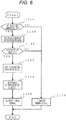
- FIG. 6 is a flowchart illustrating an operational process of a timing signal output performed by a calculation function (the timing signal generation unit 1100 and an overlap operation region determination unit 112) of the control unit 71.
- the operational process of the timing signal output is performed as an interrupt process based on a predetermined angle synchronized with a crank angle or a timer converted into an angle.
- Step 1110 is a step of determining an abnormality in the ignition coil (sub) .
- the procedure proceeds to step 1170 in which the timing signal is fixed to OFF and the process ends.
- the procedure proceeds to step 1120.
- Step 1120 is a step of retrieving an overlap operation region. It is retrieved whether there is a predetermined overlap operation region from the current operation region.
- step 1130 in a case where it is determined that the overlap discharge and a typical discharge (that is, the ignition by the ignition coil (sub) is performed or not) is determined and there is no overlap region, the procedure proceeds to step 1170, the timing signal is fixed to OFF, and the process ends. In the case of the overlap region, the procedure proceeds to step 1140.
- FIG. 7 illustrates a relation between an EGR rate and an overlap discharge region when the EGR rate (100% ⁇ EGR gas flow rate/New air flow rate) is set according to an engine speed and an engine load in a case where an EGR gas is introduced particularly for the purpose of improving a fuel efficiency.
- the execution region of the overlap discharge may be the same as the "large EGR region", but a region in which a rotation speed and a load direction are expanded more than the "large EGR region” is set.
- Such a configuration is to avoid that the EGR rate set in the "large EGR region” is introduced into the cylinder earlier than the overlap discharge so as to make the combustion worse and to reduce the performance in a case where the operation state shifts from the "small EGR region” to the large EGR region” in a short time.
- the execution region of the overlap discharge is set in a microcontroller in the control unit 71 in advance, and it is determined whether it is an operation region of the overlap discharge from the current operation state.
- Step 1140 of FIG. 6 is a step of setting an energizing time of the ignition coil (sub).
- the energizing time of the ignition coil (sub) is set in the microcontroller in the control unit 71 in advance. For example, as illustrated in FIG. 8 , the energizing time may be set to be longer as the EGR rate becomes large.
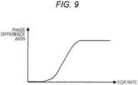
- Step 1150 of FIG. 6 is a step of setting a phase difference of the ignition coil (sub).
- a phase difference [ms] in the ignition timing of the ignition coil (main) is set.
- the phase difference of the ignition coil (sub) is set in the microcontroller in the control unit 71 in advance. For example, as illustrated in FIG. 9 , the phase difference may be set to be larger as the EGR rate becomes large.
- the timing signal is output in step 1160 according to the energizing time and the phase difference which are set in step 1140 and step 1150.
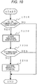
- FIG. 10 is a flowchart of the abnormality detection of step 1110 of FIG. 6 which is periodically performed by the control unit 71.
- Step 1210 of FIG. 10 is a step of determining whether the timing signal output is an ON command. In a case where it is determined that the timing signal output is the ON command from FIG. 6 , the procedure proceeds to step 1220. In a case where the timing signal is an OFF signal, this process ends.
- Step 1220 is a step of acquiring a monitor value of the timing signal. As illustrated in FIG. 2 , the timing signal 110 is input to the CPU 78 at the same time of being output, and acquired as the timing signal monitor value.
- Step 1230 is a step of determining whether the timing signal monitor value acquired in step 1220 is an ON value.
- the timing signal monitor value is an ON value (that is, the timing signal output is the ON command, and the monitor value at that time is also the ON value)
- it is determined as normal, and the process ends.
- the timing signal monitor value is an OFF value (that is, the timing signal monitor value becomes the OFF value even though the timing signal output is the ON command)
- the procedure proceeds to step 1240, and it is determined that the sub coil is abnormal.
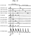
- a period from Time t1 to Time t5 illustrates an operation in the overlap region.
- a main ignition signal 1 is turned on, and the ignition coil (main) starts to be energized.
- a sub ignition signal 1 is turned on, and the ignition coil (main) starts to be energized.
- the timing signal is kept on until the energizing time previously set in step 1140 of FIG. 6 elapses.
- the main ignition signal 1 is turned off according to the ignition timing previously set at Time t2, the ignition coil (main) starts to discharge, and the secondary current rises.
- the timing signal is turned off at Time t3.
- the ignition coil (sub) starts to discharge at a timing when the sub ignition signal 1 is turned off.
- the discharge of the ignition coil (sub) is overlapped with the discharge of the ignition coil (main) . Therefore, the secondary current rises again.
- each cylinder is repeatedly performed until Time t5.
- the timing signal is fixed to OFF and the sub ignition signals of all cylinders are turned off. Therefore, only the secondary current of the ignition coil (main) remains. Further, since the ignition coil (sub) of FIG. 11 is normal, the timing signal and the timing signal monitor are identically operated.
- the main ignition signal 1 is turned on, and the ignition coil (main) starts to be energized. Since Time t1 is the overlap region, the sub ignition signal 1 is turned on and the ignition coil (main) starts to be energized when the timing signal is turned on between Time t1 and Time t2.
- the main ignition signal 1 is turned off according to the ignition timing previously set at Time t2
- the ignition coil (main) starts to discharge, and the secondary current rises.
- the timing signal is turned off at Time t3.
- the ignition coil (sub) starts to discharge at a timing when the sub ignition signal 1 is turned off.
- the secondary current does not rise because there is an abnormality in the ignition coil (sub), and it is not possible to detect the rising of the secondary current. Therefore, an abnormality is detected by the control circuit provided in the ignition coil (sub) of FIG. 4 , and the timing signal is fixed to OFF.
- a main ignition signal 2 is turned on at Time t4, and the same operation as that at Times t1, t2, and t3 is performed.
- the timing signal is fixed to OFF by the control circuit, a sub ignition signal 2 is not turned on and the timing signal monitor value is also not turned on.
- the ignition system is equipped with the ignition energy supply units of two systems for every cylinder.
- the ignition energy supply units of two systems can be controlled only by adding one signal line compared to an ignition system equipped only with the ignition energy supply units of one system. Even in the case of a multiple-cylinder internal combustion engine, it is possible to provide an engine control device which can suppress a shortage of output terminals of the control unit and an increase of costs.
- the second embodiment is different from the first embodiment in that the main ignition signal which is input to the ignition coil (sub) 30a-2 is not the main ignition signal 101a belonging to the same cylinder but the main ignition signal 101d belonging to a cylinder different from that of the ignition coil (sub) 30a-2 as illustrated in FIG. 13 .
- FIG. 14 is a diagram illustrating a detailed connection between the ignition coil (main) 30a-1 and the ignition coil (sub) 30a-2.
- the ignition coil (main) 30a-1 is configured by an ignitor, a primary coil, and a secondary coil.
- the main ignition signal 101a output from the control unit 71 is input to the ignitor, and the current of the primary coil is controlled by the main ignition signal 101a, so that the ignition of the ignition plug 33 is performed.
- the ignition coil (sub) 30a-2 is configured by an ignitor, a primary coil, a secondary coil, and a control circuit.
- the control circuit receives the main ignition signal 101d which is an ignition signal of the ignition energy supply units of the other side belonging to a cylinder different from that of the ignition coil (sub) 30a-2 and the timing signal 110. At this time, the control circuit determines whether the cylinder is an ignition cylinder using the ignition signal of the ignition energy supply units of the other side, and generates a sub ignition signal with respect to the ignition coil (sub) 30a-2 according to the energizing time commanded by the timing signal.
- the current generated in the secondary coil is controlled by controlling the current of the primary coil using the sub ignition signal output from the control circuit.
- the upstream side of the secondary coil of the ignition coil (sub) 30a-2 is connected to the downstream side of the secondary coil of the ignition coil (main) 30a-1, and the secondary coil of the ignition coil (main) 30a-1 and the secondary coil of the ignition coil (sub) 30a-2 are connected in series with respect to the ignition plug 33.
- a main ignition signal belonging to a cylinder which is used for the ignition right before the main ignition signal 101a is preferably used as the main ignition signal 101d which is an ignition signal of the ignition energy supply units of the other side belonging to a cylinder different from that of the ignition coil (sub) 30a-2.
- the main ignition signal to be input to the control circuit of the ignition coil (sub) belonging to the first cylinder is preferably the main ignition signal of the second cylinder.
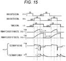
- FIG. 15 is a timing chart illustrating waveforms of the input/output of the coil 30 configured as illustrated in FIG. 14 .
- the main ignition control signal 101 a primary current with respect to the timing signal 110, and a discharge output (a secondary voltage and a secondary current) 401 in the coil 30 in a case where the air-fuel mixture compressed in one cylinder of the internal combustion engine ignites.
- This embodiment is different from the timing chart of FIG. 5 in that the timing of turning on the timing signal 110 occurs before the main ignition signal 101a.
- the control circuit illustrated in FIG. 14 determines an ignition cylinder on the basis of the main ignition signal 101d belonging to the cylinder which is subjected to the ignition right before. Therefore, it is possible to determine an ignition cylinder before the main ignition signal 101a, so that the timing of turning on the timing signal 101 is set before the main ignition signal 101a.
- the ON time of the timing signal that is, the energizing time of the ignition coil (sub)
- the ignition system equipped with the ignition energy supply units of two systems for every cylinder can control the ignition energy supply units of two systems only by adding one common signal line compared to the ignition system only equipped with the ignition energy supply units of one system. Even in the case of a multiple-cylinder internal combustion engine, it is possible to provide an engine control device which can suppress a shortage of output terminals of the control unit and an increase of costs.
- the third embodiment is different from the first embodiment in that the ignition coil (main) 30a-1 and the ignition coil (sub) 30a-2 are connected in parallel as illustrated in FIG. 16 .
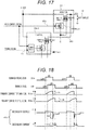
- FIG. 17 is a diagram illustrating a detailed connection between the ignition coil (main) 30a-1 and the ignition coil (sub) 30a-2.
- the ignition coil (main) 30a-1 is configured by an ignitor, a primary coil, and a secondary coil.
- the main ignition signal 101a output from the control unit 71 is input to the ignitor, and the current of the primary coil is controlled by the main ignition signal 101a, so that the ignition of the ignition plug 33 is performed.
- the ignition coil (sub) 30a-2 is configured by an ignitor, a primary coil, a secondary coil, and a control circuit.
- the control circuit receives the main ignition signal 101a which is an ignition signal of the ignition energy supply units of the other side belonging to the same cylinder as that of the ignition coil (sub) 30a-2 and the timing signal 110.
- the control circuit determines whether the cylinder is an ignition cylinder using the ignition signal of the ignition energy supply units of the other side, and generates a sub ignition signal with respect to the ignition coil (sub) 30a-2 according to the energizing time commanded by the timing signal.
- the current generated in the secondary coil is controlled by controlling the current of the primary coil using the sub ignition signal output from the control circuit.
- the upstream side of the secondary coil of the ignition coil (sub) 30a-2 is connected to the upstream side of the secondary coil of the ignition coil (main) 30a-1, and the secondary coil of the ignition coil (main) 30a-1 and the secondary coil of the ignition coil (sub) 30a-2 are connected in parallel with respect to the ignition plug 33.
- the main ignition signal which is input for the control circuit to determine an ignition cylinder may be the main ignition signal 101d which is an ignition signal of the ignition energy supply units of the other side belonging to a different cylinder as illustrated in FIG. 14 , and the main ignition signal belonging to a cylinder subjected to the ignition right before the main ignition signal 101a is preferably used.
- FIG. 18 is a timing chart illustrating waveforms of the input/output of the coil 30 configured as illustrated in FIG. 17 .
- the main ignition control signal 101 the primary currents with respect to the timing signal 110, and the discharge output (the secondary voltage and the secondary current) 401 in the coil 30 in a case where the air-fuel mixture compressed in one cylinder of the internal combustion engine ignites.
- the operation of the timing signal 110 and the operation of the primary current with respect to the timing signal 110 are the same as those of FIG. 5 , but the discharge time of the secondary current becomes short compared to the discharge time of FIG. 5 .
- the parallel connection between the ignition coil (main) and the ignition coil (sub) causes an inductance of the discharge path to be reduced compared to the series connection.
- the ignition system equipped with the ignition energy supply units of two systems for every cylinder can control the ignition energy supply units of two systems only by adding one common signal line compared to the ignition system only equipped with the ignition energy supply units of one system. Even in the case of a multiple-cylinder internal combustion engine, it is possible to provide an engine control device which can suppress a shortage of output terminals of the control unit and an increase of costs.
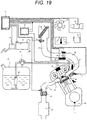
- the fourth embodiment is different from the first embodiment in that a discharge unit 72 is provided between the control unit 71 and the ignition coil 30 as illustrated in FIG. 19 .
- the discharge unit 72 detects the timing signal which is output from the control unit 71.
- a predetermined voltage for example, 500 V
- a predetermined voltage for example, 500 V
- FIG. 20 illustrates a four-cylinder engine (internal combustion engine) as an example of the engine control device according to this embodiment.
- the ignition signals 101a to 101d for the respective cylinders are output from the main ignition signal generation unit 1000 mounted in the control unit 71 to the ignition signal 101.
- the timing signal 110 is output from the timing signal generation unit 1100.
- the discharge unit 72 is provided separately from the control unit 71, and a boosting circuit 203 and the ignition coils 30a to 30d for the cylinders are connected by high voltage lines 203a to 203d (about 500 V).
- a boosting circuit 203 and the ignition coils 30a to 30d for the cylinders are connected by high voltage lines 203a to 203d (about 500 V).
- a current value required for the high voltage lines (203a to 203d) to keep the discharge state is supplied to the secondary coil.
- the engine cylinder is configured such that the discharge is caused by the ignition plugs (33a to 33d) to make the air-fuel mixture ignite and a typical discharge is kept on (so-called overlap discharge) .
- the respective portions are connected by a wire harness.
- the discharge unit 72 is configured by a control circuit 202 which controls a discharge time on the basis of information from the timing signal 110, a cylinder determination circuit 201 which determines an ignition timing of each cylinder, and the boosting circuit 203.
- a control circuit 202 which controls a discharge time on the basis of information from the timing signal 110
- a cylinder determination circuit 201 which determines an ignition timing of each cylinder
- the boosting circuit 203 When the ignition signals 101a to 101d for the cylinders and the high voltage lines 203a to 203d required for the overlap discharge are supplied to the secondary coil of the ignition coil corresponding to the respective cylinders in synchronization with the timing of the timing signal 110, the overlap discharge can be generated.
- FIG. 21 illustrates one representative cylinder configured by the ignition signal control 101a, an overlap request signal 110, the discharge unit 72, and the ignition coil 30a for each cylinder in a case where the overlap discharge is performed in this embodiment.
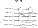
- FIG. 22 illustrates each situation of the primary current, the secondary current and voltage of the ignition coil in a case where the air-fuel mixture compressed in the cylinder of the internal combustion engine ignites.
- the discharge time control circuit 202 receives information of an input signal of the timing signal 110 to determine a time to perform the overlap discharge.
- the cylinder determination circuit 201 which determines an ignition timing of a target cylinder determines the target cylinder to which the boosting circuit 203 is performed by the ignition signal 101a.
- the high voltage line 203a required for the overlap discharge is connected to the secondary coil of the ignition coil 30a corresponding to the target cylinder in synchronization with timing of blocking the primary current so as to supply a high voltage in conjunction with a control circuit 302 in the ignition coil. Therefore, the overlap discharge can occur.
- the boosting circuit is blocked at a timing when the discharge time control circuit 202 ends the overlap discharge so as to end the overlap discharge.
- the secondary current and the secondary voltage illustrated in FIG. 22 are extended during the discharge time (tw) and the discharge voltage is continuously supplied during that time. Therefore, the ignition performance to the air-fuel mixture in the cylinder can be improved.
- the overlap request signal 110 illustrated in FIG. 22 is controlled to output the ON signal at a timing earlier by time (td) with respect to the falling edge of the ignition signal as depicted by a solid line.
- a calculation timing of the overlap request signal is not necessarily calculated at an ignition timing, but the calculation may be performed at a predetermined calculation timing of a microcontroller (for example, every 10 ms) and, while depending on a determination timing of the discharge time control circuit 202, the discharge time control circuit is able to determine information of an overlap request and information of an overlap time at a timing as early as possible when the information of the overlap request is surely output.
- the information of the discharge time (tw) is set to be ON/OFF output at every ignition timing in synchronization with the timing signal.
- the timing signal 110 may simply output an ON signal as illustrated by a broken line (that is, only information of overlap discharge ON/OFF) in a case where the control of the discharge time is independently controlled (for example, a fixed time) by the overlap control circuit 202. Further, in the case of the overlap discharge OFF mode, information indicating always OFF depicted by a dotted line is output.
- the ignition system equipped with the ignition energy supply units of two systems for every cylinder can control the ignition energy supply units of two systems only by adding one common signal line compared to the ignition system only equipped with the ignition energy supply units of one system. Even in the case of a multiple-cylinder internal combustion engine, it is possible to provide an engine control device which can suppress a shortage of output terminals of the control unit and an increase of costs.
- the fifth embodiment is an example where a 6-cylinder internal combustion engine is employed.
- the first embodiment is different from the fourth embodiment in that the timing signal generation unit is configured by two units such as a timing signal generation unit 1 and a timing signal generation unit 2 and there are two timing signals. One of the timing signals is connected to the control unit, and the other one is branched in the middle thereof. The timing signals are each connected to the plurality of ignition coils.
- the invention may be applied to an ignition system which includes the ignition energy supply units of two systems for every cylinder.
- the invention may be applied to an ignition system which includes two sets of the ignition plugs and the ignition coils for every cylinder.
Landscapes
- Engineering & Computer Science (AREA)
- Chemical & Material Sciences (AREA)
- Combustion & Propulsion (AREA)
- Mechanical Engineering (AREA)
- General Engineering & Computer Science (AREA)
- Physics & Mathematics (AREA)
- Plasma & Fusion (AREA)
- Theoretical Computer Science (AREA)
- Signal Processing (AREA)
- Ignition Installations For Internal Combustion Engines (AREA)
Abstract
Description
- The present invention relates to an engine control device which performs an ignition control to overlap spark discharges from an ignition plug of an internal combustion engine.
- In recent years, a reduction of fuel consumption of an internal combustion engine has been important. A method of improving the fuel efficiency is increasingly employed in which a large amount of EGR (Exhaust Gas Recirculation) gas is introduced in a light-loaded operation region for the purpose of low fuel consumption on the basis of the fact that pumping loss is reduced by introducing an EGR gas. However, in such a case, an inert gas is increased to reduce a ratio of the air which is newly introduced into a cylinder of the internal combustion engine, and accordingly a ratio of an appropriate air-fuel mixture is reduced around an ignition plug. Therefore, a secure ignition and a stable combustion are hardly achieved in a short-term discharge, and the internal combustion engine comes to be in an unstable state due to an incorrect combustion.
- In an ignition device for an internal combustion engine, a state of the air-fuel mixture deviates in the vicinity of the ignition plug so as to cause a state where the air-fuel ratio is reduced or a state where an inert gas such as an EGR gas is mixed. In such a state, it is considered as a very important technique that an unstable ignitionability of the air-fuel mixture is improved in a short-term discharge and the fuel efficiency of the internal combustion engine is improved by improving the ignitionability and by making the combustion stable. For example, there is a well-known technique "Ignition device of overlap discharge type for internal combustion engine" (PTL 1) as the related art.
- PTL 1:
JP 2000-240542 A - According to the ignition control of the ignition system of the overlap discharge type disclosed in
PTL 1, when an overlap discharge time is controlled, current consumption is excessively increased when the overlap discharge is performed over the entire region which may cause a defect such as deterioration and exhaustion of a battery mounted in a vehicle or the like. Therefore, an execution region of the overlap discharge is necessarily limited. In order to limit the overlap discharge region, there is a need for a control unit to give information of an overlap request signal which is used to make a limitation on a boosting circuit. - In addition, according to an ignition control of the ignition system of the overlap discharge type disclosed in
PTL 1, there is a need to supply large discharge energy to the ignition plug for a long time. Therefore, a predetermined voltage (for example, 500 V) or more is necessarily added to a discharge current of an ignition coil from a boosting circuit which is separately provided. In the case of a multiple-cylinder internal combustion engine, the boosting circuit is necessarily configured to handle the cylinders. In a case where an execution region of the overlap discharge is limited, or in a case where the ignition energy of the overlap discharge is adjusted, there is a need to transmit an overlap request signal for the cylinders from the control unit. There is a problem causing an increase of the number of outputs of the control unit, an increase of the number of signal lines connecting the control unit and the boosting circuit, a shortage of output terminals of the control unit, and an increase of costs due to an increase of the number of output circuits of the control unit and an increase of signal lines. - In
PTL 1, the ignition energy is supplied by two systems of the boosting circuit which is provided in the ignition plug separately from the ignition coil. However, an ignition system equipped with ignition energy supply units of the two systems may cause the same problem regardless of the ignition coil and the boosting circuit. - The invention has been made to solve such a problem, and an object thereof is to provide an engine control device which can suppress a shortage of output terminals of the control unit and an increase of costs even in a multiple-cylinder internal combustion engine equipped with the ignition energy supply units of two systems.
- In order to solve the technical problem, an engine control device according to the present invention is an engine control device which controls a multiple-cylinder engine in which ignition energy supply units of two systems are provided for every cylinder, wherein a signal is transmitted through a common signal line to a plurality of ignition energy supply units of one system among the ignition energy supply units of the two systems to control the ignition energy supply units of the one system.
- According to an ignition device for an internal combustion engine of the invention, there is provided an ignition system equipped with ignition energy supply units of two systems for every cylinder. The ignition energy supply units of the two systems can be controlled only by adding one signal line with respect to the ignition system equipped only with the ignition energy supply units of one system. It is possible to provide an engine control device which can suppress a shortage of output terminals of the control unit and an increase of costs even in a multiple-cylinder internal combustion engine.
-
- [
FIG. 1] FIG. 1 is a diagram illustrating a configuration of an engine control system according to an embodiment of the invention. - [
FIG. 2] FIG. 2 is a diagram illustrating a configuration of a control unit according to an embodiment of the invention. - [
FIG. 3] FIG. 3 is a diagram illustrating a configuration of an engine control system according to a first embodiment of the invention. - [
FIG. 4] FIG. 4 is a diagram for describing an ignition control device according to the first embodiment. - [
FIG. 5] FIG. 5 is a timing chart of the ignition control device according to the first embodiment. - [
FIG. 6] FIG. 6 is a flowchart of setting a timing signal according to the first embodiment. - [
FIG. 7] FIG. 7 is a diagram illustrating an overlap discharge region. - [
FIG. 8] FIG. 8 is a diagram illustrating a setting of an energizing time. - [
FIG. 9] FIG. 9 is a diagram illustrating a setting of a phase difference time - [
FIG. 10] FIG. 10 is a flowchart of an abnormality detection according to the first embodiment. - [
FIG. 11] FIG. 11 is a timing chart at a normal time of the ignition control device according to the first embodiment. - [
FIG. 12] FIG. 12 is a timing chart at a time when the ignition control device according to the first embodiment detects an abnormality. - [
FIG. 13] FIG. 13 is a diagram illustrating a configuration of an engine control system according to a second embodiment. - [
FIG. 14] FIG. 14 is a diagram for describing an ignition control device according to the second embodiment. - [
FIG. 15] FIG. 15 is a timing chart of the ignition control device according to the second embodiment. - [
FIG. 16] FIG. 16 is a diagram illustrating a configuration of an engine control system according to a third embodiment. - [
FIG. 17] FIG. 17 is a diagram for describing an ignition control device according to the third embodiment. - [
FIG. 18] FIG. 18 is a timing chart of the ignition control device according to the third embodiment. - [
FIG. 19] FIG. 19 is a diagram illustrating a configuration of an engine control system according to a fourth embodiment of the invention. - [
FIG. 20] FIG. 20 is a diagram illustrating a configuration of the engine control system according to the fourth embodiment of the invention. - [
FIG. 21] FIG. 21 is a diagram for describing an ignition control device according to the fourth embodiment. - [
FIG. 22] FIG. 22 is a timing chart of the ignition control device according to the fourth embodiment. - [
FIG. 23] FIG. 23 is a diagram illustrating a configuration of the engine control system according to the fourth embodiment of the invention. - Hereinafter, the description will be given about embodiments of the invention in detail with reference to the drawings, but the invention is not limited to the following embodiments. Various modifications and applications may be contained in the technical concept of the invention.
- First, the description will be given with reference to
FIGS. 1 to 11 about a first configuration of a control system of an internal combustion engine to which the invention is applied. Herein, the embodiment illustrated inFIG. 1 is a 4-cylinder internal combustion engine of a so-called port injection type, and an engine of a cylinder direct injection type may be applied regardless of the number of cylinders. -
FIG. 1 is a diagram illustrating a configuration of the internal combustion engine control system according to the first configuration. The air sucked into aninternal combustion engine 65 passes through anair cleaner 60, and is introduced to anair flow sensor 2 of a hot wire type. A hot-wire air flow sensor is used in theair flow sensor 2 of the hot wire type. A signal corresponding to an intake air amount is output from theair flow sensor 2 of the hot wire type, and an intake air temperature signal is output measured by the intakeair temperature sensor 2 using a thermistor. Next, the intake air passes through a connectedduct 61 and athrottle valve 40 which controls an air flow rate, and enters acollector 62. In addition, the throttle valve is operated by athrottle drive motor 42 which is driven by acontrol unit 71. The air entered thecollector 62 is distributed into intake pipes connected to the engine, and sucked into the cylinder. A valve timing variation mechanism is equipped in a valve drive system to perform a feedback control to adjust the valve to be a target angle. In addition, acrank angle sensor 7 attached to a cylinder block outputs a pulse at every predetermined crank angle, and the output is input to thecontrol unit 71. - A fuel is sucked and compressed by a
fuel pump 20 from afuel tank 21, adjusted in pressure to be a certain pressure by apressure regulator 22, and injected from aninjector 23 provided in the intake pipe into the intake pipe. - A
throttle sensor 1 is attached to thethrottle valve 40 to detect an opening of the throttle valve. A signal of the sensor is input to thecontrol unit 71 to perform a feedback control of the opening of thethrottle valve 40 and to detect a complete close position and an acceleration. Further, a target opening of the feedback control is obtained from a driver's stepping amount detected by anaccelerator opening sensor 14 and an amount of an idle rotation speed control (that is, ISC control). - A
water temperature sensor 3 is attached to theinternal combustion engine 65 to detect a coolant temperature. A signal of the sensor is input to thecontrol unit 71 to detect a warming-up state of theinternal combustion engine 65, and a target rotation speed is set at the time of increasing a fuel injection amount, correcting an ignition timing, turning on/off aradiator fan 75, and an idle operation. In addition, anair condition switch 18 which monitors a state of an air-conditioning clutch and aneutral switch 17 which is built in a transmission to monitor a state of a drive system are attached to calculate a target rotation speed at an idle time and a load correction amount. - An air-fuel ratio sensor 8 is mounted in an exhaust pipe of the engine, and outputs a signal according to an oxygen concentration in the exhaust gas. The signal is input to the
control unit 71, and used to adjust a pulse width of a fuel injection to be a target air-fuel ratio required according to an operation situation. - An
ignition coil 30 is provided with two coils (a main coil and a sub coil), each of which is connected to thecontrol unit 71. An ignition signal and a timing signal are input according to an energizing time and an ignition timing of each coil which are calculated by thecontrol unit 71. The discharging caused by the main coil and the discharging caused by the sub coil are overlapped to be output, and a spark discharge of anignition plug 33 occurs. - Next, the description will be given about an input/output signal of the
control unit 71 of an automobile according to this embodiment usingFIG. 2 . Thecontrol unit 71 is configured by aCPU 78 and apower source IC 79 as illustrated inFIG. 2 . Herein, as the signals input to thecontrol unit 71 organized using this drawing, there are input signals from the air flow sensor, the built-in intakeair temperature sensor 2, thecrank angle sensor 7, thethrottle sensor 1, thewater temperature sensor 3, anoil temperature sensor 25, and theaccelerator opening sensor 14. In addition, the output signal from thecontrol unit 71 is output to theinjector 23, afuel pump 20, the ignition coil (main) 30, atiming signal 110, and thethrottle drive motor 42. Further, thetiming signal 110 is configured to receive the output signal and to monitor an output result. - Next,
FIG. 3 illustrates a configuration of an engine control device according to this embodiment in which the 4-cylinder internal combustion engine is exemplified. First,main ignition signals 101a to 101d for cylinders are output from a main ignitionsignal generation unit 1000 mounted in thecontrol unit 71, and signal lines for transmitting the respective signals are connected to coils 30a to 30d provided in the respective cylinders. Thecoil 30a is provided with two coils of an ignition coil (main) 30a-1 and an ignition coil (sub) 30a-2 therein, and the ignition coil (main) 30a-1 and the ignition coil (sub) 30a-2 are connected to an overlappingdischarge line 203a in series. A signal line for transmitting theignition signal 101a output from thecontrol unit 71 is connected to the ignition coil (main) 30a-1 and the ignition coil (sub) 30a-2. - Next, the
timing signal 110 is output from a timingsignal generation unit 1100 mounted in thecontrol unit 71 through one common signal line. One side of the common signal line for transmitting thetiming signal 110 is connected to thecontrol unit 71, and the other side is branched in the middle thereof. The branched signal lines are connected to the ignition coils (sub) 30a-2 to 30d-2 which are disposed on a side near the control unit with respect to the ignition coil (main). With such an arrangement, the timing signal transmitted from thecontrol unit 71 is input to the ignition coils (sub) 30a-2 to 30d-2, and the outputs of the ignition coils (sub) 30a-2 to 30d-2 are input to the ignition coils (main) 30a-1 to 30d-1. - Further, in
FIG. 3 , the ignition coil (main) 30a-1 and the ignition coil (sub) 30a-2 are illustrated by onecoil 30a, and the ignition coil (main) 30a-1 and the ignition coil (sub) 30a-2 may be separately and independently configured without using thecoil 30a. - In other words, the control unit of this embodiment transmits the timing signal to a plurality of ignition energy supply units of one system (that is, a plurality of ignition coils (sub)) through a common signal line (one signal line) among ignition energy supply units of two systems illustrated by the ignition coils (main) and the ignition coils (sub) so as to control the ignition energy supply units (a plurality of ignition coils (sub)) of one system.
- In addition, a timing
signal monitor unit 1200 is provided in thecontrol unit 71 to monitor the operation of thetiming signal 110, and detects an abnormality of the ignition coil (sub) by monitoring the operation of the timing signal. Specifically, in a case where an abnormality occurs in the ignition coil (sub), thetiming signal 110 is pulled up or down in the ignition coil (sub) to fix the potential. Therefore, the timing signal monitor value detected by the timingsignal monitor unit 1200 is fixed even when thetiming signal 110 is commanded by thecontrol unit 71, so that thecontrol unit 71 can determine control and abnormality from a difference between the command of thetiming signal 110 and a monitor value. - In other words, the control unit of this embodiment receives the timing signal through the command signal line (one signal line) from the plurality of ignition energy supply units of one system (that is, the plurality of ignition coils (sub)) among the ignition energy supply units of two systems illustrated by the ignition coil (main) and the ignition coil (sub) so as to detect an abnormality of the plurality of ignition energy supply units (the plurality of ignition coils (sub)) of one system.
-
FIG. 4 is a diagram illustrating a detailed connection between the ignition coil (main) 30a-1 and the ignition coil (sub) 30a-2. The ignition coil (main) 30a-1 is configured by an ignitor, a primary coil, and a secondary coil. Themain ignition signal 101a output from thecontrol unit 71 is input to the ignitor, and the current of the primary coil is controlled by themain ignition signal 101a, so that the ignition of theignition plug 33 is performed. - The ignition coil (sub) 30a-2 is configured by an ignitor, a primary coil, a secondary coil, and a control circuit. The control circuit receives the
main ignition signal 101a which is an ignition signal of the ignition energy supply units of the other side belonging to the same cylinder as that of the ignition coil (sub) 30a-2 and thetiming signal 110. At this time, the control circuit determines whether the cylinder is an ignition cylinder using the ignition signal of the ignition energy supply units of the other side, and generates a sub ignition signal with respect to the ignition coil (sub) 30a-2 according to the energizing time commanded by the timing signal. - The current generated in the secondary coil is controlled by controlling the current of the primary coil using the sub ignition signal output from the control circuit. The upstream side of the secondary coil of the ignition coil (sub) 30a-2 is connected to the downstream side of the secondary coil of the ignition coil (main) 30a-1, and the secondary coil of the ignition coil (main) 30a-1 and the secondary coil of the ignition coil (sub) 30a-2 are connected in series with respect to the
ignition plug 33. -
FIG. 5 is a timing chart illustrating input/output waveforms of thecoil 30 configured as illustrated inFIG. 4 . Herein, there is illustrated a relation among the mainignition control signal 101, a primary current with respect to thetiming signal 110, and a discharge output (a secondary voltage and a secondary current) 401 in thecoil 30 in a case where the air-fuel mixture compressed in one cylinder of the internal combustion engine ignites. - Specifically, a transistor in an
ignitor 301a-1 is switched at an ON timing of a rising edge of a rectangular waveform of themain ignition signal 101a, and a magnetic energy is accumulated in the ignition coil (main) 30a-1 by a primary current in a range from 5 to 10 A flowing on the primary side of the ignition coil (main) 30a-1. The transistor in theignitor 301a-1 is switched at an OFF timing (so-called ignition timing) of a falling edge of a rectangular waveform of themain ignition signal 101, and the primary current is blocked. Then, a high secondary voltage is generated on the secondary side of the ignition coil (main) 30a-1, and thus the discharge starts in theignition plug 33. The secondary voltage causing the discharge is typically about 10 kV to 15 kV, and the secondary current caused by the discharge is within a range of 0.1 A for example. Then, the discharge caused by the energy emission goes on several ms. - In addition, when the
timing signal 110 transmitted through the common signal line is turned on at the same time as, or after, the turning-ON of themain ignition signal 101a, the sub ignition signal is turned on by the control circuit, a transistor in anignitor 301a-2 is switched at a timing when the sub ignition signal is turned on, and a primary current in a range of 5 to 10 A flows to the primary side of the ignition coil (sub) 30a-2. - Therefore, when the magnetic energy is accumulated in the ignition coil (sub) 30a-2, the sub ignition signal is turned off at a timing when the
timing signal 110 is turned off, the transistor in theignitor 301a-2 is switched, the primary current is blocked, a high secondary voltage (not illustrated) is generated on the secondary side of the ignition coil (sub) 30a-2, and the discharge is overlapped in theignition plug 33. Herein, the OFF timing of the falling edge of thetiming signal 110 is set to be the same as the OFF timing of themain ignition signal 101a, or to be delayed by a phase difference ΔIGN [ms], so that the discharge time can be extended compared to a case where only the ignition coil (main) 30a-1 is used for the ignition. - In addition, if a timing of shifting the
ignition control signal 101a and the timing signal 110 from ON to OFF is not appropriately controlled in consideration of a state of the air-fuel mixture in the cylinder and a load stage of the internal combustion engine, ignitionability and a combustion speed may be affected, and variation in a rotation speed and oscillation of the internal combustion engine caused by worsening combustion (worsening ignitionability) may follow. Therefore, the timing is very important since it causes a great influence on the engine performance. - In addition, the control circuit has a function of monitoring the ignition coil (sub) 30a-2, and can detect an abnormality of the ignition coil (sub) 30a-2. In a case where an abnormality is detected, the
timing signal 110 is electrically fixed to either LOW (0 V) or HIGH (5 V) in the control circuit, and the ignition coil (sub) is monitored by thecontrol unit 71, so that an abnormality can be detected by thecontrol unit 71. - Further, in this embodiment, the control circuit which outputs the sub ignition signal is provided in the ignition coil (sub) 30a-2, and may be provided in the outer side of the ignition coil (sub) 30a-2, or may be provided in the
control unit 71. -
FIG. 6 is a flowchart illustrating an operational process of a timing signal output performed by a calculation function (the timingsignal generation unit 1100 and an overlap operation region determination unit 112) of thecontrol unit 71. For example, the operational process of the timing signal output is performed as an interrupt process based on a predetermined angle synchronized with a crank angle or a timer converted into an angle. - Step 1110 is a step of determining an abnormality in the ignition coil (sub) . In a case where an abnormality is detected, the procedure proceeds to step 1170 in which the timing signal is fixed to OFF and the process ends. In a case where an abnormality is not detected, the procedure proceeds to step 1120.
- Step 1120 is a step of retrieving an overlap operation region. It is retrieved whether there is a predetermined overlap operation region from the current operation region. In step 1130, in a case where it is determined that the overlap discharge and a typical discharge (that is, the ignition by the ignition coil (sub) is performed or not) is determined and there is no overlap region, the procedure proceeds to step 1170, the timing signal is fixed to OFF, and the process ends. In the case of the overlap region, the procedure proceeds to step 1140.
- Herein, the overlap region retrieving of step 1120 will be described in detail using
FIG. 7. FIG. 7 illustrates a relation between an EGR rate and an overlap discharge region when the EGR rate (100% × EGR gas flow rate/New air flow rate) is set according to an engine speed and an engine load in a case where an EGR gas is introduced particularly for the purpose of improving a fuel efficiency. - Herein, on the basis of a combustion stability, it is roughly divided into a "large EGR region" in which the overlap discharge is necessary (for example, the EGR rate exceeds 20%) and a "small EGR region" in which the overlap discharge is not necessary. Further, the execution region of the overlap discharge may be the same as the "large EGR region", but a region in which a rotation speed and a load direction are expanded more than the "large EGR region" is set. Such a configuration is to avoid that the EGR rate set in the "large EGR region" is introduced into the cylinder earlier than the overlap discharge so as to make the combustion worse and to reduce the performance in a case where the operation state shifts from the "small EGR region" to the large EGR region" in a short time. As described above, the execution region of the overlap discharge is set in a microcontroller in the
control unit 71 in advance, and it is determined whether it is an operation region of the overlap discharge from the current operation state. -
Step 1140 ofFIG. 6 is a step of setting an energizing time of the ignition coil (sub). The energizing time of the ignition coil (sub) is set in the microcontroller in thecontrol unit 71 in advance. For example, as illustrated inFIG. 8 , the energizing time may be set to be longer as the EGR rate becomes large. -
Step 1150 ofFIG. 6 is a step of setting a phase difference of the ignition coil (sub). Instep 1150, a phase difference [ms] in the ignition timing of the ignition coil (main) is set. The phase difference of the ignition coil (sub) is set in the microcontroller in thecontrol unit 71 in advance. For example, as illustrated inFIG. 9 , the phase difference may be set to be larger as the EGR rate becomes large. The timing signal is output in step 1160 according to the energizing time and the phase difference which are set instep 1140 andstep 1150. - Next, the details of the abnormality detection of step 1110 of
FIG. 6 will be described usingFIG. 10. FIG. 10 is a flowchart of the abnormality detection of step 1110 ofFIG. 6 which is periodically performed by thecontrol unit 71. -
Step 1210 ofFIG. 10 is a step of determining whether the timing signal output is an ON command. In a case where it is determined that the timing signal output is the ON command fromFIG. 6 , the procedure proceeds to step 1220. In a case where the timing signal is an OFF signal, this process ends. -
Step 1220 is a step of acquiring a monitor value of the timing signal. As illustrated inFIG. 2 , thetiming signal 110 is input to theCPU 78 at the same time of being output, and acquired as the timing signal monitor value. -
Step 1230 is a step of determining whether the timing signal monitor value acquired instep 1220 is an ON value. In a case where the timing signal monitor value is an ON value (that is, the timing signal output is the ON command, and the monitor value at that time is also the ON value), it is determined as normal, and the process ends. In a case where the timing signal monitor value is an OFF value (that is, the timing signal monitor value becomes the OFF value even though the timing signal output is the ON command), the procedure proceeds to step 1240, and it is determined that the sub coil is abnormal. - Next, the description will be given using a timing chart of
FIG. 11 about a case where the ignition coil (sub) is normal. A period from Time t1 to Time t5 illustrates an operation in the overlap region. At Time t1, amain ignition signal 1 is turned on, and the ignition coil (main) starts to be energized. When the timing signal is turned on between Time t1 and Time t2, asub ignition signal 1 is turned on, and the ignition coil (main) starts to be energized. The timing signal is kept on until the energizing time previously set instep 1140 ofFIG. 6 elapses. When themain ignition signal 1 is turned off according to the ignition timing previously set at Time t2, the ignition coil (main) starts to discharge, and the secondary current rises. When a time from Time t2 passes a phase difference time set atstep 1150 ofFIG. 6 , the timing signal is turned off at Time t3. The ignition coil (sub) starts to discharge at a timing when thesub ignition signal 1 is turned off. The discharge of the ignition coil (sub) is overlapped with the discharge of the ignition coil (main) . Therefore, the secondary current rises again. - The ignition of each cylinder is repeatedly performed until Time t5. When it is determined that it is not an overlap region at Time t5, the timing signal is fixed to OFF and the sub ignition signals of all cylinders are turned off. Therefore, only the secondary current of the ignition coil (main) remains. Further, since the ignition coil (sub) of
FIG. 11 is normal, the timing signal and the timing signal monitor are identically operated. - Next, the description will be given using a timing chart of
FIG. 12 about a case where the ignition coil (sub) is abnormal. At Time t1, themain ignition signal 1 is turned on, and the ignition coil (main) starts to be energized. Since Time t1 is the overlap region, thesub ignition signal 1 is turned on and the ignition coil (main) starts to be energized when the timing signal is turned on between Time t1 and Time t2. When themain ignition signal 1 is turned off according to the ignition timing previously set at Time t2, the ignition coil (main) starts to discharge, and the secondary current rises. When a time from Time t2 passes a phase difference time set atstep 1150 ofFIG. 6 , the timing signal is turned off at Time t3. The ignition coil (sub) starts to discharge at a timing when thesub ignition signal 1 is turned off. However, the secondary current does not rise because there is an abnormality in the ignition coil (sub), and it is not possible to detect the rising of the secondary current. Therefore, an abnormality is detected by the control circuit provided in the ignition coil (sub) ofFIG. 4 , and the timing signal is fixed to OFF. Amain ignition signal 2 is turned on at Time t4, and the same operation as that at Times t1, t2, and t3 is performed. However, since the timing signal is fixed to OFF by the control circuit, asub ignition signal 2 is not turned on and the timing signal monitor value is also not turned on. When an abnormality of the sub coil instep 1240 ofFIG. 10 is detected at Time t6, it is out of the overlap region, and then the timing signal is fixed to OFF. - With the configuration described above, the ignition system is equipped with the ignition energy supply units of two systems for every cylinder. The ignition energy supply units of two systems can be controlled only by adding one signal line compared to an ignition system equipped only with the ignition energy supply units of one system. Even in the case of a multiple-cylinder internal combustion engine, it is possible to provide an engine control device which can suppress a shortage of output terminals of the control unit and an increase of costs.
- Next, a second embodiment of the invention will be described using
FIGS. 13 to 15 . The second embodiment is different from the first embodiment in that the main ignition signal which is input to the ignition coil (sub) 30a-2 is not themain ignition signal 101a belonging to the same cylinder but themain ignition signal 101d belonging to a cylinder different from that of the ignition coil (sub) 30a-2 as illustrated inFIG. 13 . - Next, the details will be described using
FIGS. 14 and15 .FIG. 14 is a diagram illustrating a detailed connection between the ignition coil (main) 30a-1 and the ignition coil (sub) 30a-2. The ignition coil (main) 30a-1 is configured by an ignitor, a primary coil, and a secondary coil. Themain ignition signal 101a output from thecontrol unit 71 is input to the ignitor, and the current of the primary coil is controlled by themain ignition signal 101a, so that the ignition of theignition plug 33 is performed. - The ignition coil (sub) 30a-2 is configured by an ignitor, a primary coil, a secondary coil, and a control circuit. The control circuit receives the
main ignition signal 101d which is an ignition signal of the ignition energy supply units of the other side belonging to a cylinder different from that of the ignition coil (sub) 30a-2 and thetiming signal 110. At this time, the control circuit determines whether the cylinder is an ignition cylinder using the ignition signal of the ignition energy supply units of the other side, and generates a sub ignition signal with respect to the ignition coil (sub) 30a-2 according to the energizing time commanded by the timing signal. - The current generated in the secondary coil is controlled by controlling the current of the primary coil using the sub ignition signal output from the control circuit. The upstream side of the secondary coil of the ignition coil (sub) 30a-2 is connected to the downstream side of the secondary coil of the ignition coil (main) 30a-1, and the secondary coil of the ignition coil (main) 30a-1 and the secondary coil of the ignition coil (sub) 30a-2 are connected in series with respect to the
ignition plug 33. - Herein, a main ignition signal belonging to a cylinder which is used for the ignition right before the
main ignition signal 101a is preferably used as themain ignition signal 101d which is an ignition signal of the ignition energy supply units of the other side belonging to a cylinder different from that of the ignition coil (sub) 30a-2. For example, in a case where an ignition order of a 4-cylinder engine is a first cylinder, a third cylinder, a fourth cylinder, and a second cylinder, the second cylinder is right before the first cylinder. Therefore, the main ignition signal to be input to the control circuit of the ignition coil (sub) belonging to the first cylinder is preferably the main ignition signal of the second cylinder. -
FIG. 15 is a timing chart illustrating waveforms of the input/output of thecoil 30 configured as illustrated inFIG. 14 . Herein, there is illustrated a relation among the mainignition control signal 101, a primary current with respect to thetiming signal 110, and a discharge output (a secondary voltage and a secondary current) 401 in thecoil 30 in a case where the air-fuel mixture compressed in one cylinder of the internal combustion engine ignites. - This embodiment is different from the timing chart of
FIG. 5 in that the timing of turning on thetiming signal 110 occurs before themain ignition signal 101a. Specifically, the control circuit illustrated inFIG. 14 determines an ignition cylinder on the basis of themain ignition signal 101d belonging to the cylinder which is subjected to the ignition right before. Therefore, it is possible to determine an ignition cylinder before themain ignition signal 101a, so that the timing of turning on thetiming signal 101 is set before themain ignition signal 101a. With such a configuration, the ON time of the timing signal (that is, the energizing time of the ignition coil (sub)) can be made longer than that of the method illustrated inFIGS. 4 and5 . - With the configuration described above, the ignition system equipped with the ignition energy supply units of two systems for every cylinder can control the ignition energy supply units of two systems only by adding one common signal line compared to the ignition system only equipped with the ignition energy supply units of one system. Even in the case of a multiple-cylinder internal combustion engine, it is possible to provide an engine control device which can suppress a shortage of output terminals of the control unit and an increase of costs.
- Next, a third embodiment of the invention will be described using
FIGS. 16 to 18 . The third embodiment is different from the first embodiment in that the ignition coil (main) 30a-1 and the ignition coil (sub) 30a-2 are connected in parallel as illustrated inFIG. 16 . - Next, the details will be described using
FIGS. 17 and 18. FIG. 17 is a diagram illustrating a detailed connection between the ignition coil (main) 30a-1 and the ignition coil (sub) 30a-2. The ignition coil (main) 30a-1 is configured by an ignitor, a primary coil, and a secondary coil. Themain ignition signal 101a output from thecontrol unit 71 is input to the ignitor, and the current of the primary coil is controlled by themain ignition signal 101a, so that the ignition of theignition plug 33 is performed. - The ignition coil (sub) 30a-2 is configured by an ignitor, a primary coil, a secondary coil, and a control circuit. The control circuit receives the
main ignition signal 101a which is an ignition signal of the ignition energy supply units of the other side belonging to the same cylinder as that of the ignition coil (sub) 30a-2 and thetiming signal 110. At this time, the control circuit determines whether the cylinder is an ignition cylinder using the ignition signal of the ignition energy supply units of the other side, and generates a sub ignition signal with respect to the ignition coil (sub) 30a-2 according to the energizing time commanded by the timing signal. The current generated in the secondary coil is controlled by controlling the current of the primary coil using the sub ignition signal output from the control circuit. - The upstream side of the secondary coil of the ignition coil (sub) 30a-2 is connected to the upstream side of the secondary coil of the ignition coil (main) 30a-1, and the secondary coil of the ignition coil (main) 30a-1 and the secondary coil of the ignition coil (sub) 30a-2 are connected in parallel with respect to the
ignition plug 33. - Further, the main ignition signal which is input for the control circuit to determine an ignition cylinder may be the
main ignition signal 101d which is an ignition signal of the ignition energy supply units of the other side belonging to a different cylinder as illustrated inFIG. 14 , and the main ignition signal belonging to a cylinder subjected to the ignition right before themain ignition signal 101a is preferably used. -
FIG. 18 is a timing chart illustrating waveforms of the input/output of thecoil 30 configured as illustrated inFIG. 17 . Herein, there is illustrated a relation among the mainignition control signal 101, the primary currents with respect to thetiming signal 110, and the discharge output (the secondary voltage and the secondary current) 401 in thecoil 30 in a case where the air-fuel mixture compressed in one cylinder of the internal combustion engine ignites. In this case, the operation of thetiming signal 110 and the operation of the primary current with respect to thetiming signal 110 are the same as those ofFIG. 5 , but the discharge time of the secondary current becomes short compared to the discharge time ofFIG. 5 . This is because the parallel connection between the ignition coil (main) and the ignition coil (sub) causes an inductance of the discharge path to be reduced compared to the series connection. - With the configuration described above, the ignition system equipped with the ignition energy supply units of two systems for every cylinder can control the ignition energy supply units of two systems only by adding one common signal line compared to the ignition system only equipped with the ignition energy supply units of one system. Even in the case of a multiple-cylinder internal combustion engine, it is possible to provide an engine control device which can suppress a shortage of output terminals of the control unit and an increase of costs.
- Further, in a case where a method of improving fuel efficiency by introducing a large amount of EGR gas is employed, an appropriate ratio of the air-fuel mixture about the ignition plug is reduced. Therefore, a method of extending the discharge time is employed using the series connection of the coils. In a case where there is a need to make the flow about the ignition plug faster and to supply ignition energy in a short time, the parallel connection of the coils may be employed. In addition, there may be employed a method of switching the series and parallel connections according to an engine stage.
- Next, a fourth embodiment of the invention will be described using
FIGS. 19 to 22 . The fourth embodiment is different from the first embodiment in that adischarge unit 72 is provided between thecontrol unit 71 and theignition coil 30 as illustrated inFIG. 19 . Thedischarge unit 72 detects the timing signal which is output from thecontrol unit 71. When the ignition timing is detected from the ignition signal, a predetermined voltage (for example, 500 V) or more is added to the discharge current of theignition coil 30 from a boosting circuit. - Next, the details will be described using
FIG. 20. FIG. 20 illustrates a four-cylinder engine (internal combustion engine) as an example of the engine control device according to this embodiment. First, theignition signals 101a to 101d for the respective cylinders are output from the main ignitionsignal generation unit 1000 mounted in thecontrol unit 71 to theignition signal 101. In addition, thetiming signal 110 is output from the timingsignal generation unit 1100. - The
discharge unit 72 is provided separately from thecontrol unit 71, and a boostingcircuit 203 and theignition coils 30a to 30d for the cylinders are connected byhigh voltage lines 203a to 203d (about 500 V). When the discharge starts at a typical ignition timing with respect to a target cylinder by switching the ignitors (301a to 301d) built in the respective ignition coils (30a to 30d), a current value required for the high voltage lines (203a to 203d) to keep the discharge state is supplied to the secondary coil. The engine cylinder is configured such that the discharge is caused by the ignition plugs (33a to 33d) to make the air-fuel mixture ignite and a typical discharge is kept on (so-called overlap discharge) . In addition, the respective portions are connected by a wire harness. - Herein, the
discharge unit 72 is configured by acontrol circuit 202 which controls a discharge time on the basis of information from thetiming signal 110, acylinder determination circuit 201 which determines an ignition timing of each cylinder, and the boostingcircuit 203. When theignition signals 101a to 101d for the cylinders and thehigh voltage lines 203a to 203d required for the overlap discharge are supplied to the secondary coil of the ignition coil corresponding to the respective cylinders in synchronization with the timing of thetiming signal 110, the overlap discharge can be generated. -
FIG. 21 illustrates one representative cylinder configured by theignition signal control 101a, anoverlap request signal 110, thedischarge unit 72, and theignition coil 30a for each cylinder in a case where the overlap discharge is performed in this embodiment.FIG. 22 illustrates each situation of the primary current, the secondary current and voltage of the ignition coil in a case where the air-fuel mixture compressed in the cylinder of the internal combustion engine ignites. - When the primary current is blocked by switching the
ignitor 301 at a timing of turning on the output from theignition signal 101a, a high voltage (secondary voltage) is generated in the secondary coil and the discharge starts in the ignition plug. The dischargetime control circuit 202 receives information of an input signal of thetiming signal 110 to determine a time to perform the overlap discharge. Thecylinder determination circuit 201 which determines an ignition timing of a target cylinder determines the target cylinder to which the boostingcircuit 203 is performed by theignition signal 101a. Thehigh voltage line 203a required for the overlap discharge is connected to the secondary coil of theignition coil 30a corresponding to the target cylinder in synchronization with timing of blocking the primary current so as to supply a high voltage in conjunction with a control circuit 302 in the ignition coil. Therefore, the overlap discharge can occur. The boosting circuit is blocked at a timing when the dischargetime control circuit 202 ends the overlap discharge so as to end the overlap discharge. - The secondary current and the secondary voltage illustrated in
FIG. 22 are extended during the discharge time (tw) and the discharge voltage is continuously supplied during that time. Therefore, the ignition performance to the air-fuel mixture in the cylinder can be improved. - In addition, the
overlap request signal 110 illustrated inFIG. 22 is controlled to output the ON signal at a timing earlier by time (td) with respect to the falling edge of the ignition signal as depicted by a solid line. This is because a calculation timing of the overlap request signal is not necessarily calculated at an ignition timing, but the calculation may be performed at a predetermined calculation timing of a microcontroller (for example, every 10 ms) and, while depending on a determination timing of the dischargetime control circuit 202, the discharge time control circuit is able to determine information of an overlap request and information of an overlap time at a timing as early as possible when the information of the overlap request is surely output. At least (td) is preferably the same timing as a timing when the ignition signal control is turned off (td = 0) or before that timing. - In the embodiment, the information of the discharge time (tw) is set to be ON/OFF output at every ignition timing in synchronization with the timing signal. As another method, the
timing signal 110 may simply output an ON signal as illustrated by a broken line (that is, only information of overlap discharge ON/OFF) in a case where the control of the discharge time is independently controlled (for example, a fixed time) by theoverlap control circuit 202. Further, in the case of the overlap discharge OFF mode, information indicating always OFF depicted by a dotted line is output. - With the configuration described above, the ignition system equipped with the ignition energy supply units of two systems for every cylinder can control the ignition energy supply units of two systems only by adding one common signal line compared to the ignition system only equipped with the ignition energy supply units of one system. Even in the case of a multiple-cylinder internal combustion engine, it is possible to provide an engine control device which can suppress a shortage of output terminals of the control unit and an increase of costs.
- Next, a fifth embodiment of the invention will be described using
FIG. 23 . - The fifth embodiment is an example where a 6-cylinder internal combustion engine is employed. The first embodiment is different from the fourth embodiment in that the timing signal generation unit is configured by two units such as a timing
signal generation unit 1 and a timingsignal generation unit 2 and there are two timing signals. One of the timing signals is connected to the control unit, and the other one is branched in the middle thereof. The timing signals are each connected to the plurality of ignition coils. - With the configuration described above, even in the case of a multiple-cylinder internal combustion engine, it is possible to provide an engine control device which can suppress a shortage of output terminals of the control unit and an increase of costs.
- Hitherto, the description has been given about five embodiments, but the contents do not depend on these embodiments. The invention may be applied to an ignition system which includes the ignition energy supply units of two systems for every cylinder. For example, the invention may be applied to an ignition system which includes two sets of the ignition plugs and the ignition coils for every cylinder.
-
- 1
- throttle sensor
- 2
- air flow sensor
- 3
- water temperature sensor
- 7
- crank angle sensor
- 14
- accelerator sensor
- 17
- neutral switch
- 18
- air condition switch
- 19
- auxiliary load switch
- 23
- injector
- 30
- ignition coil
- 42
- throttle drive motor
Claims (19)
- An engine control device which controls a multiple-cylinder engine in which ignition energy supply units of two systems are provided for every cylinder,
wherein a signal is transmitted through a common signal line to a plurality of ignition energy supply units of one system among the ignition energy supply units of the two systems to control the ignition energy supply units of the one system. - The engine control device according to claim 1,
wherein the ignition energy supply units of the two systems are configured to overlap a discharge of the ignition energy supply units of the one system and a discharge of the ignition energy supply units of the other system to be output. - The engine control device according to claim 1,
wherein the plurality of ignition energy supply units having received a signal through the common signal line determine an ignition cylinder using an ignition signal of the ignition energy supply units of the other system. - The engine control device according to claim 3,
wherein the ignition signal of the ignition energy supply units of the other system to be used for determining the ignition cylinder is an ignition signal of the ignition energy supply units of the other system belonging to the same cylinder as that of the ignition energy supply units of the one system. - The engine control device according to claim 3,
wherein the ignition signal of the ignition energy supply units of the other system to be used for determining the ignition cylinder is an ignition signal of the ignition energy supply units of the other system belonging to a cylinder which ignites right before the ignition cylinder. - The engine control device according to claim 4 or 5,
wherein a signal to be transmitted through the command signal line is turned on at the same time as, or after, a time when the ignition signal of the ignition energy supply units of the other system is turned on. - The engine control device according to claim 1,
wherein one side of the common signal line is connected to the engine control device, the other side is branched in the middle thereof, and the branched signal lines are each connected to the plurality of ignition energy supply units of the one system. - The engine control device according to claim 1,
wherein the ignition energy supply units of the two systems are each configured by coils, and a coil of the one system and a coil of the other system are disposed in series, and
wherein the common signal line is connected to a coil of a system which is disposed on a side near the engine control device among the ignition energy supply units of the two systems. - The engine control device according to claim 1,
wherein the ignition energy supply units of the two systems are each configured by coils, and a coil of the one system and a coil of the other system are disposed in series, and
wherein one side of the common signal line is connected to the engine control device, the other side is branched in the middle thereof, and the branched signal lines are each connected to a control circuit which is provided in correspondence with the coils of the one system among the ignition energy supply units of the two systems. - The engine control device according to claim 1,
wherein the ignition energy supply units of the two systems are each configured by coils, and a coil of the one system and a coil of the other system are disposed in parallel, and
wherein the common signal line is connected to a control circuit which is provided in correspondence with each coil of the one system among the ignition energy supply units of the two systems. - The engine control device according to claim 1,
wherein an energizing time of the ignition energy supply unit is controlled by the common signal line. - The engine control device according to claim 1,
wherein the ignition energy supply units of the two systems are configured by a discharge unit of an overlap discharge type which is provided with a coil and a boosting circuit to extend time for a spark discharge, and
wherein the common signal line is connected to the discharge unit among the ignition energy supply units of the two systems. - The engine control device according to claim 1,
wherein a discharge time of the ignition energy supply units is controlled by the common signal line. - The engine control device according to claim 1,
wherein a discharge allowance of the ignition energy supply units is controlled by the common signal line. - An engine control device which controls a multiple-cylinder engine in which ignition energy supply units of two systems are provided for every cylinder,
wherein a signal is received through a common signal line from a plurality of ignition energy supply units of one system among the ignition energy supply units of the two systems to detect an abnormality of the plurality of ignition energy supply units of the one system. - The engine control device according to claim 15,
wherein an ignition energy supply unit to which the command signal line is connected is stopped in a case where an abnormality is detected. - An engine control system, comprising:ignition energy supply units of two systems which are provided for every cylinder of a multiple-cylinder engine; and,an engine control device which controls the ignition energy supply units of the two systems,wherein the engine control device transmits a signal through a command signal line to a plurality of ignition energy supply units of one system among the ignition energy supply units of the two systems to control the plurality of ignition energy supply units of the one system.
- The engine control system according to claim 17,
wherein the ignition energy supply units of the two systems are configured to overlap a discharge of the ignition energy supply units of the one system and a discharge of the ignition energy supply units of the other system to be output. - The engine control system according to claim 17,
wherein one side of the common signal line is connected to the engine control device, the other side is branched in the middle thereof, and the branched signal lines are each connected to the plurality of ignition energy supply units of the one system.
Applications Claiming Priority (2)
| Application Number | Priority Date | Filing Date | Title |
|---|---|---|---|
| JP2015140951 | 2015-07-15 | ||
| PCT/JP2016/069582 WO2017010310A1 (en) | 2015-07-15 | 2016-07-01 | Engine control device |
Publications (3)
| Publication Number | Publication Date |
|---|---|
| EP3324036A1 true EP3324036A1 (en) | 2018-05-23 |
| EP3324036A4 EP3324036A4 (en) | 2019-02-20 |
| EP3324036B1 EP3324036B1 (en) | 2025-03-05 |
Family
ID=57757842
Family Applications (1)
| Application Number | Title | Priority Date | Filing Date |
|---|---|---|---|
| EP16824290.7A Active EP3324036B1 (en) | 2015-07-15 | 2016-07-01 | Engine control device |
Country Status (5)
| Country | Link |
|---|---|
| US (1) | US10309366B2 (en) |
| EP (1) | EP3324036B1 (en) |
| JP (1) | JP6476295B2 (en) |
| CN (1) | CN107709756B (en) |
| WO (1) | WO2017010310A1 (en) |
Families Citing this family (12)
| Publication number | Priority date | Publication date | Assignee | Title |
|---|---|---|---|---|
| JP2018178997A (en) * | 2017-04-20 | 2018-11-15 | 株式会社デンソー | Ignition system for internal combustion engine |
| WO2018193909A1 (en) * | 2017-04-20 | 2018-10-25 | 株式会社デンソー | Internal combustion engine ignition system |
| JP7040289B2 (en) * | 2018-05-25 | 2022-03-23 | 株式会社デンソー | Internal combustion engine ignition system |
| JP7087676B2 (en) * | 2018-05-25 | 2022-06-21 | 株式会社デンソー | Internal combustion engine ignition control device |
| JP7077811B2 (en) * | 2018-06-19 | 2022-05-31 | 株式会社デンソー | Internal combustion engine ignition control system |
| CN113167205B (en) * | 2018-12-07 | 2022-11-18 | 三菱电机株式会社 | Ignition device |
| WO2020121515A1 (en) * | 2018-12-14 | 2020-06-18 | 三菱電機株式会社 | Ignition device |
| JP7196741B2 (en) * | 2019-04-09 | 2022-12-27 | 株式会社デンソー | ignition controller |
| WO2020235219A1 (en) | 2019-05-23 | 2020-11-26 | 日立オートモティブシステムズ株式会社 | Control device for internal combustion engine |
| JP7331772B2 (en) * | 2020-05-01 | 2023-08-23 | 株式会社デンソー | ignition controller |
| JP7412599B2 (en) * | 2020-12-07 | 2024-01-12 | 日立Astemo株式会社 | Internal combustion engine control device |
| KR102948496B1 (en) * | 2021-02-05 | 2026-04-03 | 현대자동차 주식회사 | Control system of ignition coil and method thereof |
Family Cites Families (19)
| Publication number | Priority date | Publication date | Assignee | Title |
|---|---|---|---|---|
| JPS6483863A (en) * | 1987-09-28 | 1989-03-29 | Hanshin Electrics | Igniting method for internal combustion engine |
| JP3508258B2 (en) * | 1994-09-09 | 2004-03-22 | 株式会社デンソー | Ignition device for internal combustion engine |
| JP2000240542A (en) | 1999-02-18 | 2000-09-05 | Hanshin Electric Co Ltd | Lap discharging type ignition device for internal combustion engine |
| JP2002295354A (en) * | 2001-03-30 | 2002-10-09 | Diamond Electric Mfg Co Ltd | Ignition device for internal combustion engine |
| US6761156B2 (en) * | 2002-02-20 | 2004-07-13 | Daimlerchrysler Corporation | Multiplexed single wire control and diagnosis of an electrical object |
| JP2007120374A (en) * | 2005-10-27 | 2007-05-17 | Kokusan Denki Co Ltd | Capacitor discharge type internal combustion engine ignition device |
| JP4736942B2 (en) | 2006-05-17 | 2011-07-27 | 株式会社デンソー | Multiple discharge ignition device |
| JP4477607B2 (en) * | 2006-07-25 | 2010-06-09 | 日立オートモティブシステムズ株式会社 | Ignition device for internal combustion engine |
| JP4803008B2 (en) | 2006-12-05 | 2011-10-26 | 株式会社デンソー | Ignition control device for internal combustion engine |
| JP4431168B2 (en) | 2007-10-30 | 2010-03-10 | 三菱電機株式会社 | Combustion state detection apparatus and combustion state detection method for internal combustion engine |
| US8490598B2 (en) * | 2009-08-20 | 2013-07-23 | Ford Global Technologies, Llc | Ignition coil with ionization and digital feedback for an internal combustion engine |
| US10502176B2 (en) * | 2012-10-15 | 2019-12-10 | Ford Global Technologies, Llc | System and method for delivering spark to an engine |
| DE102013111299B4 (en) * | 2012-10-15 | 2025-10-23 | Ford Global Technologies, Llc | System and method for delivering a spark to a machine |
| US9605644B2 (en) | 2013-06-06 | 2017-03-28 | Ford Global Technologies, Llc | Dual coil ignition system |
| JP6078432B2 (en) * | 2013-07-25 | 2017-02-08 | 日立オートモティブシステムズ株式会社 | Ignition device for internal combustion engine and ignition control device used therefor |
| US9617965B2 (en) * | 2013-12-16 | 2017-04-11 | Transient Plasma Systems, Inc. | Repetitive ignition system for enhanced combustion |
| KR20150072265A (en) * | 2013-12-19 | 2015-06-29 | 현대오트론 주식회사 | Apparatus for trouble diagnostics of ignition system |
| US9458773B2 (en) * | 2014-05-15 | 2016-10-04 | Ford Global Technologies, Llc | Method and system for ignition energy control |
| US9695792B2 (en) * | 2015-07-24 | 2017-07-04 | Ford Global Technologies, Llc | System and method for operating an ignition system |
-
2016
- 2016-07-01 CN CN201680038452.6A patent/CN107709756B/en active Active
- 2016-07-01 JP JP2017528382A patent/JP6476295B2/en active Active
- 2016-07-01 EP EP16824290.7A patent/EP3324036B1/en active Active
- 2016-07-01 WO PCT/JP2016/069582 patent/WO2017010310A1/en not_active Ceased
- 2016-07-01 US US15/741,526 patent/US10309366B2/en active Active
Also Published As
| Publication number | Publication date |
|---|---|
| JPWO2017010310A1 (en) | 2018-04-19 |
| US10309366B2 (en) | 2019-06-04 |
| EP3324036A4 (en) | 2019-02-20 |
| EP3324036B1 (en) | 2025-03-05 |
| CN107709756B (en) | 2019-05-10 |
| WO2017010310A1 (en) | 2017-01-19 |
| JP6476295B2 (en) | 2019-02-27 |
| CN107709756A (en) | 2018-02-16 |
| US20180195485A1 (en) | 2018-07-12 |
Similar Documents
| Publication | Publication Date | Title |
|---|---|---|
| EP3324036B1 (en) | Engine control device | |
| US10302062B2 (en) | Ignition control apparatus | |
| US9771918B2 (en) | Ignition system | |
| RU145341U1 (en) | ENGINE SPARK SYSTEM | |
| US10590829B2 (en) | Control device for internal combustion engine and control method for cooling device | |
| US9822753B2 (en) | Ignition control device | |
| JP6239463B2 (en) | Ignition control device for internal combustion engine | |
| JP5843047B2 (en) | Ignition control device and ignition control method for internal combustion engine | |
| JP2014020210A (en) | Suction air volume measuring device for engine | |
| JP2018003635A (en) | Control device of internal combustion engine | |
| KR20200020920A (en) | Ignition | |
| US20180258840A1 (en) | Exhaust turbine power generating system and control device for the same | |
| JP2004143969A (en) | Cooling control device for internal combustion engine | |
| JP6411951B2 (en) | Control device for internal combustion engine | |
| JP2014062494A (en) | Control device of internal combustion engine | |
| JP4894540B2 (en) | AC generator power generation control device | |
| US9334825B2 (en) | Fuel supply apparatus for internal combustion engine | |
| JPH09130989A (en) | Alternator control unit | |
| JP6252324B2 (en) | Control device for internal combustion engine | |
| JP2018178735A (en) | Exhaust turbine power generation system and its control device | |
| JP5868075B2 (en) | Generator control device | |
| JP2023095395A (en) | engine controller | |
| JP2021131075A (en) | Spark ignition type internal combustion engine | |
| JP2014109196A (en) | Control device for internal combustion engine | |
| JP2007255300A (en) | Idle stabilization controlling device of engine |
Legal Events
| Date | Code | Title | Description |
|---|---|---|---|
| STAA | Information on the status of an ep patent application or granted ep patent |
Free format text: STATUS: THE INTERNATIONAL PUBLICATION HAS BEEN MADE |
|
| PUAI | Public reference made under article 153(3) epc to a published international application that has entered the european phase |
Free format text: ORIGINAL CODE: 0009012 |
|
| STAA | Information on the status of an ep patent application or granted ep patent |
Free format text: STATUS: REQUEST FOR EXAMINATION WAS MADE |
|
| 17P | Request for examination filed |
Effective date: 20180102 |
|
| AK | Designated contracting states |
Kind code of ref document: A1 Designated state(s): AL AT BE BG CH CY CZ DE DK EE ES FI FR GB GR HR HU IE IS IT LI LT LU LV MC MK MT NL NO PL PT RO RS SE SI SK SM TR |
|
| AX | Request for extension of the european patent |
Extension state: BA ME |
|
| TPAC | Observations filed by third parties |
Free format text: ORIGINAL CODE: EPIDOSNTIPA |
|
| DAV | Request for validation of the european patent (deleted) | ||
| DAX | Request for extension of the european patent (deleted) | ||
| TPAC | Observations filed by third parties |
Free format text: ORIGINAL CODE: EPIDOSNTIPA |
|
| A4 | Supplementary search report drawn up and despatched |
Effective date: 20190121 |
|
| RIC1 | Information provided on ipc code assigned before grant |
Ipc: F02P 15/02 20060101ALI20190115BHEP Ipc: F02P 17/00 20060101ALI20190115BHEP Ipc: F02P 3/00 20060101AFI20190115BHEP Ipc: F02P 17/12 20060101ALI20190115BHEP Ipc: F02P 15/10 20060101ALI20190115BHEP |
|
| RAP3 | Party data changed (applicant data changed or rights of an application transferred) |
Owner name: HITACHI ASTEMO, LTD. |
|
| STAA | Information on the status of an ep patent application or granted ep patent |
Free format text: STATUS: EXAMINATION IS IN PROGRESS |
|
| 17Q | First examination report despatched |
Effective date: 20211214 |
|
| REG | Reference to a national code |
Ref country code: DE Ref legal event code: R079 Free format text: PREVIOUS MAIN CLASS: F02P0003000000 Ipc: F02P0015100000 Ref country code: DE Ref legal event code: R079 Ref document number: 602016091464 Country of ref document: DE Free format text: PREVIOUS MAIN CLASS: F02P0003000000 Ipc: F02P0015100000 |
|
| RIC1 | Information provided on ipc code assigned before grant |
Ipc: F02P 5/15 20060101ALI20240813BHEP Ipc: F02P 9/00 20060101ALI20240813BHEP Ipc: F02P 3/04 20060101ALI20240813BHEP Ipc: F02P 15/10 20060101AFI20240813BHEP |
|
| GRAP | Despatch of communication of intention to grant a patent |
Free format text: ORIGINAL CODE: EPIDOSNIGR1 |
|
| STAA | Information on the status of an ep patent application or granted ep patent |
Free format text: STATUS: GRANT OF PATENT IS INTENDED |
|
| INTG | Intention to grant announced |
Effective date: 20241029 |
|
| GRAS | Grant fee paid |
Free format text: ORIGINAL CODE: EPIDOSNIGR3 |
|
| GRAA | (expected) grant |
Free format text: ORIGINAL CODE: 0009210 |
|
| STAA | Information on the status of an ep patent application or granted ep patent |
Free format text: STATUS: THE PATENT HAS BEEN GRANTED |
|
| AK | Designated contracting states |
Kind code of ref document: B1 Designated state(s): AL AT BE BG CH CY CZ DE DK EE ES FI FR GB GR HR HU IE IS IT LI LT LU LV MC MK MT NL NO PL PT RO RS SE SI SK SM TR |
|
| REG | Reference to a national code |
Ref country code: GB Ref legal event code: FG4D |
|
| REG | Reference to a national code |
Ref country code: CH Ref legal event code: EP |
|
| REG | Reference to a national code |
Ref country code: DE Ref legal event code: R096 Ref document number: 602016091464 Country of ref document: DE |
|
| REG | Reference to a national code |
Ref country code: IE Ref legal event code: FG4D |
|
| PG25 | Lapsed in a contracting state [announced via postgrant information from national office to epo] |
Ref country code: RS Free format text: LAPSE BECAUSE OF FAILURE TO SUBMIT A TRANSLATION OF THE DESCRIPTION OR TO PAY THE FEE WITHIN THE PRESCRIBED TIME-LIMIT Effective date: 20250605 |
|
| PG25 | Lapsed in a contracting state [announced via postgrant information from national office to epo] |
Ref country code: FI Free format text: LAPSE BECAUSE OF FAILURE TO SUBMIT A TRANSLATION OF THE DESCRIPTION OR TO PAY THE FEE WITHIN THE PRESCRIBED TIME-LIMIT Effective date: 20250305 |
|
| REG | Reference to a national code |
Ref country code: NL Ref legal event code: MP Effective date: 20250305 |
|
| PG25 | Lapsed in a contracting state [announced via postgrant information from national office to epo] |
Ref country code: ES Free format text: LAPSE BECAUSE OF FAILURE TO SUBMIT A TRANSLATION OF THE DESCRIPTION OR TO PAY THE FEE WITHIN THE PRESCRIBED TIME-LIMIT Effective date: 20250305 |
|
| REG | Reference to a national code |
Ref country code: LT Ref legal event code: MG9D |
|
| PG25 | Lapsed in a contracting state [announced via postgrant information from national office to epo] |
Ref country code: NO Free format text: LAPSE BECAUSE OF FAILURE TO SUBMIT A TRANSLATION OF THE DESCRIPTION OR TO PAY THE FEE WITHIN THE PRESCRIBED TIME-LIMIT Effective date: 20250605 |
|
| PG25 | Lapsed in a contracting state [announced via postgrant information from national office to epo] |
Ref country code: HR Free format text: LAPSE BECAUSE OF FAILURE TO SUBMIT A TRANSLATION OF THE DESCRIPTION OR TO PAY THE FEE WITHIN THE PRESCRIBED TIME-LIMIT Effective date: 20250305 |
|
| PG25 | Lapsed in a contracting state [announced via postgrant information from national office to epo] |
Ref country code: LV Free format text: LAPSE BECAUSE OF FAILURE TO SUBMIT A TRANSLATION OF THE DESCRIPTION OR TO PAY THE FEE WITHIN THE PRESCRIBED TIME-LIMIT Effective date: 20250305 |
|
| PG25 | Lapsed in a contracting state [announced via postgrant information from national office to epo] |
Ref country code: GR Free format text: LAPSE BECAUSE OF FAILURE TO SUBMIT A TRANSLATION OF THE DESCRIPTION OR TO PAY THE FEE WITHIN THE PRESCRIBED TIME-LIMIT Effective date: 20250606 Ref country code: BG Free format text: LAPSE BECAUSE OF FAILURE TO SUBMIT A TRANSLATION OF THE DESCRIPTION OR TO PAY THE FEE WITHIN THE PRESCRIBED TIME-LIMIT Effective date: 20250305 |
|
| REG | Reference to a national code |
Ref country code: AT Ref legal event code: MK05 Ref document number: 1773126 Country of ref document: AT Kind code of ref document: T Effective date: 20250305 |
|
| PG25 | Lapsed in a contracting state [announced via postgrant information from national office to epo] |
Ref country code: NL Free format text: LAPSE BECAUSE OF FAILURE TO SUBMIT A TRANSLATION OF THE DESCRIPTION OR TO PAY THE FEE WITHIN THE PRESCRIBED TIME-LIMIT Effective date: 20250305 |
|
| PG25 | Lapsed in a contracting state [announced via postgrant information from national office to epo] |
Ref country code: SE Free format text: LAPSE BECAUSE OF FAILURE TO SUBMIT A TRANSLATION OF THE DESCRIPTION OR TO PAY THE FEE WITHIN THE PRESCRIBED TIME-LIMIT Effective date: 20250305 |
|
| PG25 | Lapsed in a contracting state [announced via postgrant information from national office to epo] |
Ref country code: SM Free format text: LAPSE BECAUSE OF FAILURE TO SUBMIT A TRANSLATION OF THE DESCRIPTION OR TO PAY THE FEE WITHIN THE PRESCRIBED TIME-LIMIT Effective date: 20250305 |
|
| PG25 | Lapsed in a contracting state [announced via postgrant information from national office to epo] |
Ref country code: PT Free format text: LAPSE BECAUSE OF FAILURE TO SUBMIT A TRANSLATION OF THE DESCRIPTION OR TO PAY THE FEE WITHIN THE PRESCRIBED TIME-LIMIT Effective date: 20250707 |
|
| PGFP | Annual fee paid to national office [announced via postgrant information from national office to epo] |
Ref country code: DE Payment date: 20250724 Year of fee payment: 10 |
|
| PG25 | Lapsed in a contracting state [announced via postgrant information from national office to epo] |
Ref country code: PL Free format text: LAPSE BECAUSE OF FAILURE TO SUBMIT A TRANSLATION OF THE DESCRIPTION OR TO PAY THE FEE WITHIN THE PRESCRIBED TIME-LIMIT Effective date: 20250305 Ref country code: IT Free format text: LAPSE BECAUSE OF FAILURE TO SUBMIT A TRANSLATION OF THE DESCRIPTION OR TO PAY THE FEE WITHIN THE PRESCRIBED TIME-LIMIT Effective date: 20250305 |
|
| PG25 | Lapsed in a contracting state [announced via postgrant information from national office to epo] |
Ref country code: AT Free format text: LAPSE BECAUSE OF FAILURE TO SUBMIT A TRANSLATION OF THE DESCRIPTION OR TO PAY THE FEE WITHIN THE PRESCRIBED TIME-LIMIT Effective date: 20250305 |
|
| PG25 | Lapsed in a contracting state [announced via postgrant information from national office to epo] |
Ref country code: EE Free format text: LAPSE BECAUSE OF FAILURE TO SUBMIT A TRANSLATION OF THE DESCRIPTION OR TO PAY THE FEE WITHIN THE PRESCRIBED TIME-LIMIT Effective date: 20250305 Ref country code: CZ Free format text: LAPSE BECAUSE OF FAILURE TO SUBMIT A TRANSLATION OF THE DESCRIPTION OR TO PAY THE FEE WITHIN THE PRESCRIBED TIME-LIMIT Effective date: 20250305 |
|
| PG25 | Lapsed in a contracting state [announced via postgrant information from national office to epo] |
Ref country code: RO Free format text: LAPSE BECAUSE OF FAILURE TO SUBMIT A TRANSLATION OF THE DESCRIPTION OR TO PAY THE FEE WITHIN THE PRESCRIBED TIME-LIMIT Effective date: 20250305 |
|
| PG25 | Lapsed in a contracting state [announced via postgrant information from national office to epo] |
Ref country code: SK Free format text: LAPSE BECAUSE OF FAILURE TO SUBMIT A TRANSLATION OF THE DESCRIPTION OR TO PAY THE FEE WITHIN THE PRESCRIBED TIME-LIMIT Effective date: 20250305 |
|
| PG25 | Lapsed in a contracting state [announced via postgrant information from national office to epo] |
Ref country code: IS Free format text: LAPSE BECAUSE OF FAILURE TO SUBMIT A TRANSLATION OF THE DESCRIPTION OR TO PAY THE FEE WITHIN THE PRESCRIBED TIME-LIMIT Effective date: 20250705 |
|
| REG | Reference to a national code |
Ref country code: DE Ref legal event code: R097 Ref document number: 602016091464 Country of ref document: DE |
|
| PLBE | No opposition filed within time limit |
Free format text: ORIGINAL CODE: 0009261 |
|
| STAA | Information on the status of an ep patent application or granted ep patent |
Free format text: STATUS: NO OPPOSITION FILED WITHIN TIME LIMIT |
|
| PG25 | Lapsed in a contracting state [announced via postgrant information from national office to epo] |
Ref country code: DK Free format text: LAPSE BECAUSE OF FAILURE TO SUBMIT A TRANSLATION OF THE DESCRIPTION OR TO PAY THE FEE WITHIN THE PRESCRIBED TIME-LIMIT Effective date: 20250305 |
|
| REG | Reference to a national code |
Ref country code: CH Ref legal event code: L10 Free format text: ST27 STATUS EVENT CODE: U-0-0-L10-L00 (AS PROVIDED BY THE NATIONAL OFFICE) Effective date: 20260114 |
|
| 26N | No opposition filed |
Effective date: 20251208 |
|
| REG | Reference to a national code |
Ref country code: CH Ref legal event code: H13 Free format text: ST27 STATUS EVENT CODE: U-0-0-H10-H13 (AS PROVIDED BY THE NATIONAL OFFICE) Effective date: 20260224 |
|
| PG25 | Lapsed in a contracting state [announced via postgrant information from national office to epo] |
Ref country code: LU Free format text: LAPSE BECAUSE OF NON-PAYMENT OF DUE FEES Effective date: 20250701 |
|
| GBPC | Gb: european patent ceased through non-payment of renewal fee |
Effective date: 20250701 |
|
| REG | Reference to a national code |
Ref country code: BE Ref legal event code: MM Effective date: 20250731 |
|
| PG25 | Lapsed in a contracting state [announced via postgrant information from national office to epo] |
Ref country code: GB Free format text: LAPSE BECAUSE OF NON-PAYMENT OF DUE FEES Effective date: 20250701 |
|
| PG25 | Lapsed in a contracting state [announced via postgrant information from national office to epo] |
Ref country code: BE Free format text: LAPSE BECAUSE OF NON-PAYMENT OF DUE FEES Effective date: 20250731 |
|
| PG25 | Lapsed in a contracting state [announced via postgrant information from national office to epo] |
Ref country code: FR Free format text: LAPSE BECAUSE OF NON-PAYMENT OF DUE FEES Effective date: 20250731 |
|
| PG25 | Lapsed in a contracting state [announced via postgrant information from national office to epo] |
Ref country code: CH Free format text: LAPSE BECAUSE OF NON-PAYMENT OF DUE FEES Effective date: 20250731 |