EP3324027A1 - Staged high temperature heat exchanger - Google Patents
Staged high temperature heat exchanger Download PDFInfo
- Publication number
- EP3324027A1 EP3324027A1 EP17191899.8A EP17191899A EP3324027A1 EP 3324027 A1 EP3324027 A1 EP 3324027A1 EP 17191899 A EP17191899 A EP 17191899A EP 3324027 A1 EP3324027 A1 EP 3324027A1
- Authority
- EP
- European Patent Office
- Prior art keywords
- flow
- hex
- fluid
- manifold
- high temperature
- Prior art date
- Legal status (The legal status is an assumption and is not a legal conclusion. Google has not performed a legal analysis and makes no representation as to the accuracy of the status listed.)
- Granted
Links
Images



Classifications
-
- F—MECHANICAL ENGINEERING; LIGHTING; HEATING; WEAPONS; BLASTING
- F28—HEAT EXCHANGE IN GENERAL
- F28F—DETAILS OF HEAT-EXCHANGE AND HEAT-TRANSFER APPARATUS, OF GENERAL APPLICATION
- F28F21/00—Constructions of heat-exchange apparatus characterised by the selection of particular materials
- F28F21/08—Constructions of heat-exchange apparatus characterised by the selection of particular materials of metal
- F28F21/081—Heat exchange elements made from metals or metal alloys
- F28F21/087—Heat exchange elements made from metals or metal alloys from nickel or nickel alloys
-
- F—MECHANICAL ENGINEERING; LIGHTING; HEATING; WEAPONS; BLASTING
- F01—MACHINES OR ENGINES IN GENERAL; ENGINE PLANTS IN GENERAL; STEAM ENGINES
- F01D—NON-POSITIVE DISPLACEMENT MACHINES OR ENGINES, e.g. STEAM TURBINES
- F01D25/00—Component parts, details, or accessories, not provided for in, or of interest apart from, other groups
- F01D25/08—Cooling; Heating; Heat-insulation
- F01D25/12—Cooling
-
- F—MECHANICAL ENGINEERING; LIGHTING; HEATING; WEAPONS; BLASTING
- F02—COMBUSTION ENGINES; HOT-GAS OR COMBUSTION-PRODUCT ENGINE PLANTS
- F02C—GAS-TURBINE PLANTS; AIR INTAKES FOR JET-PROPULSION PLANTS; CONTROLLING FUEL SUPPLY IN AIR-BREATHING JET-PROPULSION PLANTS
- F02C7/00—Features, components parts, details or accessories, not provided for in, or of interest apart form groups F02C1/00 - F02C6/00; Air intakes for jet-propulsion plants
- F02C7/12—Cooling of plants
- F02C7/16—Cooling of plants characterised by cooling medium
- F02C7/18—Cooling of plants characterised by cooling medium the medium being gaseous, e.g. air
-
- F—MECHANICAL ENGINEERING; LIGHTING; HEATING; WEAPONS; BLASTING
- F02—COMBUSTION ENGINES; HOT-GAS OR COMBUSTION-PRODUCT ENGINE PLANTS
- F02K—JET-PROPULSION PLANTS
- F02K3/00—Plants including a gas turbine driving a compressor or a ducted fan
- F02K3/08—Plants including a gas turbine driving a compressor or a ducted fan with supplementary heating of the working fluid; Control thereof
- F02K3/105—Heating the by-pass flow
- F02K3/115—Heating the by-pass flow by means of indirect heat exchange
-
- F—MECHANICAL ENGINEERING; LIGHTING; HEATING; WEAPONS; BLASTING
- F28—HEAT EXCHANGE IN GENERAL
- F28F—DETAILS OF HEAT-EXCHANGE AND HEAT-TRANSFER APPARATUS, OF GENERAL APPLICATION
- F28F9/00—Casings; Header boxes; Auxiliary supports for elements; Auxiliary members within casings
- F28F9/02—Header boxes; End plates
-
- F—MECHANICAL ENGINEERING; LIGHTING; HEATING; WEAPONS; BLASTING
- F05—INDEXING SCHEMES RELATING TO ENGINES OR PUMPS IN VARIOUS SUBCLASSES OF CLASSES F01-F04
- F05D—INDEXING SCHEME FOR ASPECTS RELATING TO NON-POSITIVE-DISPLACEMENT MACHINES OR ENGINES, GAS-TURBINES OR JET-PROPULSION PLANTS
- F05D2220/00—Application
- F05D2220/30—Application in turbines
- F05D2220/32—Application in turbines in gas turbines
-
- F—MECHANICAL ENGINEERING; LIGHTING; HEATING; WEAPONS; BLASTING
- F05—INDEXING SCHEMES RELATING TO ENGINES OR PUMPS IN VARIOUS SUBCLASSES OF CLASSES F01-F04
- F05D—INDEXING SCHEME FOR ASPECTS RELATING TO NON-POSITIVE-DISPLACEMENT MACHINES OR ENGINES, GAS-TURBINES OR JET-PROPULSION PLANTS
- F05D2250/00—Geometry
- F05D2250/70—Shape
- F05D2250/75—Shape given by its similarity to a letter, e.g. T-shaped
-
- F—MECHANICAL ENGINEERING; LIGHTING; HEATING; WEAPONS; BLASTING
- F05—INDEXING SCHEMES RELATING TO ENGINES OR PUMPS IN VARIOUS SUBCLASSES OF CLASSES F01-F04
- F05D—INDEXING SCHEME FOR ASPECTS RELATING TO NON-POSITIVE-DISPLACEMENT MACHINES OR ENGINES, GAS-TURBINES OR JET-PROPULSION PLANTS
- F05D2260/00—Function
- F05D2260/20—Heat transfer, e.g. cooling
- F05D2260/213—Heat transfer, e.g. cooling by the provision of a heat exchanger within the cooling circuit
-
- F—MECHANICAL ENGINEERING; LIGHTING; HEATING; WEAPONS; BLASTING
- F05—INDEXING SCHEMES RELATING TO ENGINES OR PUMPS IN VARIOUS SUBCLASSES OF CLASSES F01-F04
- F05D—INDEXING SCHEME FOR ASPECTS RELATING TO NON-POSITIVE-DISPLACEMENT MACHINES OR ENGINES, GAS-TURBINES OR JET-PROPULSION PLANTS
- F05D2300/00—Materials; Properties thereof
- F05D2300/10—Metals, alloys or intermetallic compounds
- F05D2300/17—Alloys
- F05D2300/172—Copper alloys
- F05D2300/1723—Nickel-Copper alloy, e.g. Monel
-
- F—MECHANICAL ENGINEERING; LIGHTING; HEATING; WEAPONS; BLASTING
- F05—INDEXING SCHEMES RELATING TO ENGINES OR PUMPS IN VARIOUS SUBCLASSES OF CLASSES F01-F04
- F05D—INDEXING SCHEME FOR ASPECTS RELATING TO NON-POSITIVE-DISPLACEMENT MACHINES OR ENGINES, GAS-TURBINES OR JET-PROPULSION PLANTS
- F05D2300/00—Materials; Properties thereof
- F05D2300/10—Metals, alloys or intermetallic compounds
- F05D2300/17—Alloys
- F05D2300/175—Superalloys
-
- F—MECHANICAL ENGINEERING; LIGHTING; HEATING; WEAPONS; BLASTING
- F05—INDEXING SCHEMES RELATING TO ENGINES OR PUMPS IN VARIOUS SUBCLASSES OF CLASSES F01-F04
- F05D—INDEXING SCHEME FOR ASPECTS RELATING TO NON-POSITIVE-DISPLACEMENT MACHINES OR ENGINES, GAS-TURBINES OR JET-PROPULSION PLANTS
- F05D2300/00—Materials; Properties thereof
- F05D2300/10—Metals, alloys or intermetallic compounds
- F05D2300/17—Alloys
- F05D2300/177—Ni - Si alloys
-
- F—MECHANICAL ENGINEERING; LIGHTING; HEATING; WEAPONS; BLASTING
- F05—INDEXING SCHEMES RELATING TO ENGINES OR PUMPS IN VARIOUS SUBCLASSES OF CLASSES F01-F04
- F05D—INDEXING SCHEME FOR ASPECTS RELATING TO NON-POSITIVE-DISPLACEMENT MACHINES OR ENGINES, GAS-TURBINES OR JET-PROPULSION PLANTS
- F05D2300/00—Materials; Properties thereof
- F05D2300/60—Properties or characteristics given to material by treatment or manufacturing
- F05D2300/607—Monocrystallinity
-
- F—MECHANICAL ENGINEERING; LIGHTING; HEATING; WEAPONS; BLASTING
- F28—HEAT EXCHANGE IN GENERAL
- F28D—HEAT-EXCHANGE APPARATUS, NOT PROVIDED FOR IN ANOTHER SUBCLASS, IN WHICH THE HEAT-EXCHANGE MEDIA DO NOT COME INTO DIRECT CONTACT
- F28D1/00—Heat-exchange apparatus having stationary conduit assemblies for one heat-exchange medium only, the media being in contact with different sides of the conduit wall, in which the other heat-exchange medium is a large body of fluid, e.g. domestic or motor car radiators
- F28D1/02—Heat-exchange apparatus having stationary conduit assemblies for one heat-exchange medium only, the media being in contact with different sides of the conduit wall, in which the other heat-exchange medium is a large body of fluid, e.g. domestic or motor car radiators with heat-exchange conduits immersed in the body of fluid
- F28D1/04—Heat-exchange apparatus having stationary conduit assemblies for one heat-exchange medium only, the media being in contact with different sides of the conduit wall, in which the other heat-exchange medium is a large body of fluid, e.g. domestic or motor car radiators with heat-exchange conduits immersed in the body of fluid with tubular conduits
- F28D1/053—Heat-exchange apparatus having stationary conduit assemblies for one heat-exchange medium only, the media being in contact with different sides of the conduit wall, in which the other heat-exchange medium is a large body of fluid, e.g. domestic or motor car radiators with heat-exchange conduits immersed in the body of fluid with tubular conduits the conduits being straight
- F28D1/05316—Assemblies of conduits connected to common headers, e.g. core type radiators
-
- F—MECHANICAL ENGINEERING; LIGHTING; HEATING; WEAPONS; BLASTING
- F28—HEAT EXCHANGE IN GENERAL
- F28D—HEAT-EXCHANGE APPARATUS, NOT PROVIDED FOR IN ANOTHER SUBCLASS, IN WHICH THE HEAT-EXCHANGE MEDIA DO NOT COME INTO DIRECT CONTACT
- F28D1/00—Heat-exchange apparatus having stationary conduit assemblies for one heat-exchange medium only, the media being in contact with different sides of the conduit wall, in which the other heat-exchange medium is a large body of fluid, e.g. domestic or motor car radiators
- F28D1/02—Heat-exchange apparatus having stationary conduit assemblies for one heat-exchange medium only, the media being in contact with different sides of the conduit wall, in which the other heat-exchange medium is a large body of fluid, e.g. domestic or motor car radiators with heat-exchange conduits immersed in the body of fluid
- F28D1/04—Heat-exchange apparatus having stationary conduit assemblies for one heat-exchange medium only, the media being in contact with different sides of the conduit wall, in which the other heat-exchange medium is a large body of fluid, e.g. domestic or motor car radiators with heat-exchange conduits immersed in the body of fluid with tubular conduits
- F28D1/053—Heat-exchange apparatus having stationary conduit assemblies for one heat-exchange medium only, the media being in contact with different sides of the conduit wall, in which the other heat-exchange medium is a large body of fluid, e.g. domestic or motor car radiators with heat-exchange conduits immersed in the body of fluid with tubular conduits the conduits being straight
- F28D1/05316—Assemblies of conduits connected to common headers, e.g. core type radiators
- F28D1/05325—Assemblies of conduits connected to common headers, e.g. core type radiators with particular pattern of flow, e.g. change of flow direction
-
- F—MECHANICAL ENGINEERING; LIGHTING; HEATING; WEAPONS; BLASTING
- F28—HEAT EXCHANGE IN GENERAL
- F28D—HEAT-EXCHANGE APPARATUS, NOT PROVIDED FOR IN ANOTHER SUBCLASS, IN WHICH THE HEAT-EXCHANGE MEDIA DO NOT COME INTO DIRECT CONTACT
- F28D21/00—Heat-exchange apparatus not covered by any of the groups F28D1/00 - F28D20/00
- F28D2021/0019—Other heat exchangers for particular applications; Heat exchange systems not otherwise provided for
- F28D2021/0026—Other heat exchangers for particular applications; Heat exchange systems not otherwise provided for for combustion engines, e.g. for gas turbines or for Stirling engines
-
- F—MECHANICAL ENGINEERING; LIGHTING; HEATING; WEAPONS; BLASTING
- F28—HEAT EXCHANGE IN GENERAL
- F28F—DETAILS OF HEAT-EXCHANGE AND HEAT-TRANSFER APPARATUS, OF GENERAL APPLICATION
- F28F2265/00—Safety or protection arrangements; Arrangements for preventing malfunction
-
- Y—GENERAL TAGGING OF NEW TECHNOLOGICAL DEVELOPMENTS; GENERAL TAGGING OF CROSS-SECTIONAL TECHNOLOGIES SPANNING OVER SEVERAL SECTIONS OF THE IPC; TECHNICAL SUBJECTS COVERED BY FORMER USPC CROSS-REFERENCE ART COLLECTIONS [XRACs] AND DIGESTS
- Y02—TECHNOLOGIES OR APPLICATIONS FOR MITIGATION OR ADAPTATION AGAINST CLIMATE CHANGE
- Y02T—CLIMATE CHANGE MITIGATION TECHNOLOGIES RELATED TO TRANSPORTATION
- Y02T50/00—Aeronautics or air transport
- Y02T50/60—Efficient propulsion technologies, e.g. for aircraft
Definitions
- the present disclosure relates to gas turbine engines, and, more specifically, to heat exchangers (HEX) for cooling air of gas turbine engines.
- HEX heat exchangers
- a heat exchanger may be provided to cool hot air in a gas turbine engine.
- a high temperature heat exchanger (HEX) is disclosed herein, in accordance with various embodiments.
- a high temperature heat exchanger (HEX) may comprise an inlet manifold comprising a first material and configured to receive a flow of fluid, an outlet manifold comprising a second material whereby the flow of fluid exits the HEX, wherein the first material comprises a nickel-based super alloy.
- the first material may comprise a single crystal alloy.
- the nickel-based superalloy may have at least 40% of a Ni 3 (Al,X) precipitate phase, X being a metallic or refractory element other than Al.
- the high temperature HEX may further comprise an intermediary manifold configured to couple the inlet manifold to the outlet manifold.
- the HEX may be at least partially located within a flow of bypass air configured to flow through a portion of the inlet manifold and a portion of the outlet manifold and remove heat from the flow of fluid.
- the intermediary manifold may comprise the first material.
- the intermediary manifold may comprise a "U" shape configured to turn the flow of fluid, the inlet manifold located upstream of the outlet manifold.
- the second material may comprise a nickel alloy.
- a staged high temperature heat exchanger (HEX) is disclosed herein, in accordance with various embodiments.
- a staged high temperature heat exchanger (HEX) may comprise a first stage made from a first material comprising an inlet manifold configured to receive a flow of fluid, and a second stage made from a second material comprising an outlet manifold whereby the flow of fluid exits the HEX, wherein the first stage is configured to withstand a temperature of the flow of fluid entering the inlet manifold and configured to reduce the temperature of the flow of fluid to an intermediate temperature before the flow of fluid reaches the second stage.
- the first material may comprise a single crystal alloy.
- the first material may comprise a nickel-based superalloy having at least 40% of a Ni 3 (Al,X) precipitate phase, X being a metallic or refractory element other than Al.
- the intermediate temperature may comprise less than about 1,200 °F.
- the staged high temperature HEX may further comprise an intermediary manifold configured to couple the inlet manifold to the outlet manifold.
- the HEX may be at least partially located within a flow of bypass air configured to flow through a portion of the inlet manifold and a portion of the outlet manifold and remove heat from the flow of fluid.
- the HEX may comprise a plurality of fins whereby heat is transferred from the HEX to the bypass air.
- the staged high temperature HEX may further comprise a spring element coupled between the inlet manifold and the outlet manifold.
- a gas turbine engine may comprise a staged high temperature heat exchanger (HEX) comprising a first stage made from a first material comprising an inlet manifold configured to receive a flow of fluid, and a second stage made from a second material comprising an outlet manifold whereby the flow of fluid exits the HEX, wherein the first stage is configured to withstand a temperature of the flow of fluid entering the inlet manifold and configured to reduce the temperature of the flow of fluid to an intermediate temperature before the flow of fluid reaches the second stage, and the first material comprises a nickel-based superalloy having at least 40% of a Ni 3 (Al,X) precipitate phase, X being a metallic or refractory element other than Al.
- HEX staged high temperature heat exchanger
- the first material may comprise a single crystal nickel alloy.
- the temperature of the flow of fluid entering the inlet manifold may be between about 1,200 °F and about 1,800 °F.
- the intermediate temperature may comprise less than about 1,200 °F.
- any reference to attached, fixed, connected or the like may include permanent, removable, temporary, partial, full and/or any other possible attachment option. Additionally, any reference to without contact (or similar phrases) may also include reduced contact or minimal contact. Surface shading lines may be used throughout the figures to denote different parts but not necessarily to denote the same or different materials. In some cases, reference coordinates may be specific to each figure.
- a heat exchanger may comprise a first stage comprising a first material and a second stage comprising a second material.
- the first material may comprise a precipitation hardened nickel superalloy, including but not limited to single crystal alloys.
- the described first stage can reduce the temperature of a flow of fluid, such as a flow of air for example, to be cooled by the HEX to a temperature suitable for the second stage.
- tail refers to the direction associated with the tail (e.g., the back end) of an aircraft, or generally, to the direction of exhaust of the gas turbine.
- forward refers to the direction associated with the nose (e.g., the front end) of an aircraft, or generally, to the direction of flight or motion.
- FIG. 1 illustrates a schematic view of a gas turbine engine, in accordance with various embodiments.
- Gas turbine engine 110 may include core engine 120. Core air flow C flows through core engine 120 and is expelled through exhaust outlet 118 surrounding tail cone 122.
- Core engine 120 drives a fan 114 arranged in a bypass flow path B.
- Air in bypass flow-path B flows in the aft direction (z-direction) along bypass flow-path B.
- At least a portion of bypass flow path B may be defined by nacelle 112 and inner fixed structure (IFS) 126.
- Fan case 132 may surround fan 114. Fan case 132 may be housed within nacelle 112.
- Nacelle 112 typically comprises two halves which are typically mounted to a pylon. According to various embodiments, multiple guide vanes 116 may extend radially between core engine 120 and intermediary case (IMC) 134. Upper bifurcation 144 and lower bifurcation 142 may extend radially between the nacelle 112 and IFS 126 in locations opposite one another to accommodate engine components such as wires and fluids, for example.
- IMC intermediary case
- Inner fixed structure 126 surrounds core engine 120 and provides core compartments 128.
- Various components may be provided in core compartment 128 such as fluid conduits and/or a compressed air duct, for example.
- Compressed air ducts may be under high pressure and may supply compressed air from a compressor stage to a turbine stage, for example.
- HEX 100 may include first stage 210 and a second stage 220.
- First stage 210 may comprise a first material comprising a high temperature superalloy.
- the superalloy is a nickel-based superally having at least 40% of a Ni 3 (Al,X) precipitate phase, where X is a metallic or refractory element other than Al. This is typically a gamma-prime phase, depending on the identity of X and the conditions under which the precipitate is formed.
- the superalloy can be formed as a single crystal. The superalloy may have increased creep strength in comparison to conventional nickel alloys.
- the superalloy may comprise increased thermal and pressure resilience.
- a first stage 210 comprising a superalloy may withstand temperatures of over 1200 °F (648.9 °C) and up to 1800 °F (982.2 °C) or more, at which temperatures a conventional nickel alloy would have inferior thermal and pressure properties.
- Second stage 220 may comprise a second material, comprising a conventional nickel-based alloy, or an early-generation superalloy such as Waspaloy®, Haynes 25, or INCO 625. None of these can achieve gamma-prime precipitate levels of more than 25%. The lower level of gamma-prime precipitates in these alloys may simplify manufacturing methods but the alloys have less resilience to temperature and pressure, particularly as compared to newer superalloys used for other components (airfoils, disks, etc.).
- a conventionally formed heat exchanger may more quickly break down due to creep, fatigue, etc., allowing leakage and necessitating frequent replacement, or may require large wall thickness to deal with thermal loading and pressure loading, which may lead to creep and stress rupture.
- a first stage comprising the first material, or superalloy may result in increased thermal and pressure resilience, as well as weight savings and decreased size.
- first stage 210 may receive a flow of fluid 230 comprising an inlet temperature T in and an inlet pressure P in .
- the temperature T in of the flow of fluid 230 may decrease across first stage 210.
- the pressure P in of the flow of fluid 230 may decrease across first stage 210.
- the flow of fluid 230 may then enter the second stage 220.
- the temperature of the flow of fluid 230 may decrease across second stage 220.
- the pressure of the flow of fluid 230 may decrease across second stage 220.
- gas turbine engine 110 may include HEX 100.
- HEX 100 may be located within a bypass flow path, such as bypass flow path B.
- HEX 100 may be included in other turbine engine applications, such as turbojet engines for military aircraft.
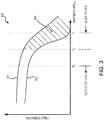
- a plot 300 of the yield strength of a first material and a second material versus temperature is illustrated, in accordance with various embodiments.
- Line 301 represents the yield strength of the first material.
- Line 302 represents the yield strength of the second material.
- the yield strength of the first material may be greater than the yield strength of the second material at an inlet temperature T i .
- the yield strength of the second material may not be sufficient to withstand pressure and thermal stress at inlet temperature T i .
- the inlet temperature T i may be greater than about 1100 °F (593.3 °C), and in various embodiments, greater than about 1200 °F (648.9 °C), and in various embodiments, greater than about 1300 °F (704.4 °C), wherein the term "about” in this regard means ⁇ 50 °F ( ⁇ 27.8 °C).
- the flow of fluid 230 may decrease in temperature as it passes through first stage 210 until it reaches intermediate temperature T m .
- the intermediate temperature T m may be less than about 1200 °F (648.9 °C), and in various embodiments, less than about 1100 °F (593.3 °C), and in various embodiments, less than about 1000 °F (537.8 °C), wherein the term "about” in this regard means ⁇ 50 °F ( ⁇ 27.8 °C).
- the yield strength of the second material may be sufficient to withstand pressure and thermal stress at intermediate temperature T m .
- the flow of fluid 230 may decrease in temperature as it passes through second stage 220 until it reaches outlet temperature T o .
- shaded region 304 represents a region of additional beneficial strength of HEX 100 in comparison to conventional heat exchangers.
- a first stage 210 capable of withstanding higher temperatures, may allow for the HEX 200 to provide cooling to a flow of fluid 230 comprising high temperatures (e.g., temperatures greater than about 1200 °F (648.9 °C)).
- the wall thickness of a staged HEX 200 may be less than the wall thickness of a conventional heat exchanger and thus the overall weight of HEX 200 may be less than a conventional heat exchanger.
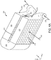
- FIG. 4A and FIG. 4B elements with like element numbering as depicted in FIG. 2 are intended to be the same and will not necessarily be repeated for the sake of clarity.
- HEX 200 may comprise a first stage 210 and a second stage 220.
- First stage 210 may comprise an inlet manifold 212.
- Second stage 220 may comprise an outlet manifold 222.
- inlet manifold 212 may be coupled to outlet manifold 222 via an intermediary manifold 202.
- intermediary manifold 202 may comprise a "U" shape.
- intermediary manifold 202 may comprise any suitable geometry.
- HEX 200 may receive a flow of fluid 230 at inlet manifold 212.
- the flow of fluid 230 may exit inlet manifold 212 into intermediary manifold 202.
- Flow of fluid 230 may be turned by intermediary manifold 202 and exit into outlet manifold 222.
- Flow of fluid 230 may flow through outlet manifold 222 and exit outlet manifold 222.
- the flow of fluid 230 exiting the outlet manifold 222 may be cooler than the flow of fluid 230 entering the inlet manifold 212.
- HEX 200 may be positioned at least partially within a flow of bypass air 240.
- Bypass air 240 may comprise a temperature substantially lower than the temperature of the flow of fluid 230.
- Inlet manifold 212 may be configured to transfer heat from flow of fluid 230 to bypass air 240.
- bypass air 240 may flow over a portion of HEX 200 to remove heat from flow of fluid 230.
- bypass air 240 may flow over plurality of fins 214 of inlet manifold 212, whereby heat is transferred from flow of fluid 230.
- bypass air 240 may continue to flow over plurality of fins 224 of outlet manifold 222, whereby heat is transferred from flow of fluid 230.
- outlet manifold 222 may be configured to transfer heat from flow of fluid 230 to bypass air 240.
- a spring element 250 may be coupled between inlet manifold 212 and outlet manifold 222.
- Spring element 250 may allow for movement (in the z-direction) of inlet manifold 212 relative to outlet manifold 222, for example during thermal expansion and/or contraction of inlet manifold 212 and/or outlet manifold 222.
- Spring element 250 may provide structural support between inlet manifold 212 and outlet manifold 222.
- spring element 250 may comprise a leaf spring, a coil spring, a beam spring, or other compliant connection.
- spring element 250 may comprise metal.
- spring element 250 may comprise sheet metal.
- inlet manifold 212 may comprise the first material.
- plurality of fins 214 may comprise the first material.
- outlet manifold 222 may comprise the second material.
- HEX 400 may be similar to HEX 200, with momentary reference to FIG. 2 , except that inlet manifold 212 and outlet manifold 222 may be disposed in the same plane (i.e., the xy-plane of FIG. 4B ) normal to the flow of bypass air 240.
- intermediary manifold 402 may couple inlet manifold 212 to outlet manifold 222.
- intermediary manifold 402 may comprise the first material.
- intermediary manifold 402 may comprise the second material.
- references to "various embodiments”, “one embodiment”, “an embodiment”, “an example embodiment”, etc. indicate that the embodiment described may include a particular feature, structure, or characteristic, but every embodiment may not necessarily include the particular feature, structure, or characteristic. Moreover, such phrases are not necessarily referring to the same embodiment. Further, when a particular feature, structure, or characteristic is described in connection with an embodiment, it is submitted that it is within the knowledge of one skilled in the art to affect such feature, structure, or characteristic in connection with other embodiments whether or not explicitly described. After reading the description, it will be apparent to one skilled in the relevant art(s) how to implement the disclosure in alternative embodiments.
Landscapes
- Engineering & Computer Science (AREA)
- Mechanical Engineering (AREA)
- General Engineering & Computer Science (AREA)
- Chemical & Material Sciences (AREA)
- Combustion & Propulsion (AREA)
- Physics & Mathematics (AREA)
- Thermal Sciences (AREA)
- Turbine Rotor Nozzle Sealing (AREA)
Abstract
Description
- The present disclosure relates to gas turbine engines, and, more specifically, to heat exchangers (HEX) for cooling air of gas turbine engines.
- As higher pressures are achieved in compressors of gas turbine engines, the temperature of compressed air in and/or leaving the compressors may increase as well. As a result, various components in a gas turbine engine may experience thermal stress. Thus, a heat exchanger (HEX) may be provided to cool hot air in a gas turbine engine.
- A high temperature heat exchanger (HEX) is disclosed herein, in accordance with various embodiments. A high temperature heat exchanger (HEX) may comprise an inlet manifold comprising a first material and configured to receive a flow of fluid, an outlet manifold comprising a second material whereby the flow of fluid exits the HEX, wherein the first material comprises a nickel-based super alloy.
- The first material may comprise a single crystal alloy. The nickel-based superalloy may have at least 40% of a Ni3(Al,X) precipitate phase, X being a metallic or refractory element other than Al. The high temperature HEX may further comprise an intermediary manifold configured to couple the inlet manifold to the outlet manifold. The HEX may be at least partially located within a flow of bypass air configured to flow through a portion of the inlet manifold and a portion of the outlet manifold and remove heat from the flow of fluid. The intermediary manifold may comprise the first material. The intermediary manifold may comprise a "U" shape configured to turn the flow of fluid, the inlet manifold located upstream of the outlet manifold. The second material may comprise a nickel alloy.
- A staged high temperature heat exchanger (HEX) is disclosed herein, in accordance with various embodiments. A staged high temperature heat exchanger (HEX) may comprise a first stage made from a first material comprising an inlet manifold configured to receive a flow of fluid, and a second stage made from a second material comprising an outlet manifold whereby the flow of fluid exits the HEX, wherein the first stage is configured to withstand a temperature of the flow of fluid entering the inlet manifold and configured to reduce the temperature of the flow of fluid to an intermediate temperature before the flow of fluid reaches the second stage.
- In various embodiments, the first material may comprise a single crystal alloy. The first material may comprise a nickel-based superalloy having at least 40% of a Ni3(Al,X) precipitate phase, X being a metallic or refractory element other than Al. The intermediate temperature may comprise less than about 1,200 °F. The staged high temperature HEX may further comprise an intermediary manifold configured to couple the inlet manifold to the outlet manifold. The HEX may be at least partially located within a flow of bypass air configured to flow through a portion of the inlet manifold and a portion of the outlet manifold and remove heat from the flow of fluid. The HEX may comprise a plurality of fins whereby heat is transferred from the HEX to the bypass air. The staged high temperature HEX may further comprise a spring element coupled between the inlet manifold and the outlet manifold.
- A gas turbine engine is disclosed herein, in accordance with various embodiments. A gas turbine engine may comprise a staged high temperature heat exchanger (HEX) comprising a first stage made from a first material comprising an inlet manifold configured to receive a flow of fluid, and a second stage made from a second material comprising an outlet manifold whereby the flow of fluid exits the HEX, wherein the first stage is configured to withstand a temperature of the flow of fluid entering the inlet manifold and configured to reduce the temperature of the flow of fluid to an intermediate temperature before the flow of fluid reaches the second stage, and the first material comprises a nickel-based superalloy having at least 40% of a Ni3(Al,X) precipitate phase, X being a metallic or refractory element other than Al.
- In various embodiments, the first material may comprise a single crystal nickel alloy. The temperature of the flow of fluid entering the inlet manifold may be between about 1,200 °F and about 1,800 °F. The intermediate temperature may comprise less than about 1,200 °F.
- The forgoing features and elements may be combined in various combinations without exclusivity, unless expressly indicated herein otherwise. These features and elements as well as the operation of the disclosed embodiments will become more apparent in light of the following description and accompanying drawings.
- The subject matter of the present disclosure is particularly pointed out and distinctly claimed in the concluding portion of the specification. A more complete understanding of the present disclosure, however, may best be obtained by referring to the detailed description and claims when considered in connection with the figures, wherein like numerals denote like elements.
-
FIG. 1 illustrates a cross-sectional view of an exemplary gas turbine engine, in accordance with various embodiments; -
FIG. 2 illustrates a schematic view of a staged high temperature heat exchanger (HEX), in accordance with various embodiments; -
FIG. 3 illustrates a plot of yield strength versus temperature of a first material and a second material, in accordance with various embodiments; -
FIG. 4A illustrates a perspective view of a staged high temperature HEX, in accordance with various embodiments; and -
FIG. 4B illustrates a perspective view of a staged high temperature HEX, in accordance with various embodiments. - The detailed description of exemplary embodiments herein makes reference to the accompanying drawings, which show exemplary embodiments by way of illustration. While these exemplary embodiments are described in sufficient detail to enable those skilled in the art to practice the inventions, it should be understood that other embodiments may be realized and that logical changes and adaptations in design and construction may be made in accordance with this invention and the teachings herein. Thus, the detailed description herein is presented for purposes of illustration only and not of limitation. The scope of the invention is defined by the appended claims. For example, the steps recited in any of the method or process descriptions may be executed in any order and are not necessarily limited to the order presented. Furthermore, any reference to singular includes plural embodiments, and any reference to more than one component or step may include a singular embodiment or step. Also, any reference to attached, fixed, connected or the like may include permanent, removable, temporary, partial, full and/or any other possible attachment option. Additionally, any reference to without contact (or similar phrases) may also include reduced contact or minimal contact. Surface shading lines may be used throughout the figures to denote different parts but not necessarily to denote the same or different materials. In some cases, reference coordinates may be specific to each figure.
- A heat exchanger (HEX), as described herein, may comprise a first stage comprising a first material and a second stage comprising a second material. The first material may comprise a precipitation hardened nickel superalloy, including but not limited to single crystal alloys. The described first stage can reduce the temperature of a flow of fluid, such as a flow of air for example, to be cooled by the HEX to a temperature suitable for the second stage.
- As used herein, "aft" refers to the direction associated with the tail (e.g., the back end) of an aircraft, or generally, to the direction of exhaust of the gas turbine. As used herein, "forward" refers to the direction associated with the nose (e.g., the front end) of an aircraft, or generally, to the direction of flight or motion.
-
FIG. 1 illustrates a schematic view of a gas turbine engine, in accordance with various embodiments.Gas turbine engine 110 may includecore engine 120. Core air flow C flows throughcore engine 120 and is expelled throughexhaust outlet 118 surroundingtail cone 122. -
Core engine 120 drives afan 114 arranged in a bypass flow path B. Air in bypass flow-path B flows in the aft direction (z-direction) along bypass flow-path B. At least a portion of bypass flow path B may be defined bynacelle 112 and inner fixed structure (IFS) 126.Fan case 132 may surroundfan 114.Fan case 132 may be housed withinnacelle 112. - Nacelle 112 typically comprises two halves which are typically mounted to a pylon. According to various embodiments,
multiple guide vanes 116 may extend radially betweencore engine 120 and intermediary case (IMC) 134.Upper bifurcation 144 andlower bifurcation 142 may extend radially between thenacelle 112 and IFS 126 in locations opposite one another to accommodate engine components such as wires and fluids, for example. - Inner
fixed structure 126 surroundscore engine 120 and provides core compartments 128. Various components may be provided incore compartment 128 such as fluid conduits and/or a compressed air duct, for example. Compressed air ducts may be under high pressure and may supply compressed air from a compressor stage to a turbine stage, for example. - With reference to
FIG. 2 , a staged, high temperature heat exchanger (HEX) 100 is illustrated, in accordance with various embodiments.HEX 100 may includefirst stage 210 and asecond stage 220.First stage 210 may comprise a first material comprising a high temperature superalloy. In various embodiments, the superalloy is a nickel-based superally having at least 40% of a Ni3(Al,X) precipitate phase, where X is a metallic or refractory element other than Al. This is typically a gamma-prime phase, depending on the identity of X and the conditions under which the precipitate is formed. The superalloy can be formed as a single crystal. The superalloy may have increased creep strength in comparison to conventional nickel alloys. In this regard, the superalloy may comprise increased thermal and pressure resilience. In this regard, afirst stage 210 comprising a superalloy may withstand temperatures of over 1200 °F (648.9 °C) and up to 1800 °F (982.2 °C) or more, at which temperatures a conventional nickel alloy would have inferior thermal and pressure properties. -
Second stage 220 may comprise a second material, comprising a conventional nickel-based alloy, or an early-generation superalloy such as Waspaloy®, Haynes 25, or INCO 625. None of these can achieve gamma-prime precipitate levels of more than 25%. The lower level of gamma-prime precipitates in these alloys may simplify manufacturing methods but the alloys have less resilience to temperature and pressure, particularly as compared to newer superalloys used for other components (airfoils, disks, etc.). Thus as exposure to temperatures and pressure differentials increase, e.g., temperatures beyond 1200 °F (649 °C), a conventionally formed heat exchanger may more quickly break down due to creep, fatigue, etc., allowing leakage and necessitating frequent replacement, or may require large wall thickness to deal with thermal loading and pressure loading, which may lead to creep and stress rupture. Thus, a first stage comprising the first material, or superalloy, may result in increased thermal and pressure resilience, as well as weight savings and decreased size. - In various embodiments,
first stage 210 may receive a flow offluid 230 comprising an inlet temperature Tin and an inlet pressure Pin. The temperature Tin of the flow offluid 230 may decrease acrossfirst stage 210. The pressure Pin of the flow offluid 230 may decrease acrossfirst stage 210. The flow offluid 230 may then enter thesecond stage 220. The temperature of the flow offluid 230 may decrease acrosssecond stage 220. The pressure of the flow offluid 230 may decrease acrosssecond stage 220. With combined reference toFIG. 1 andFIG. 2 ,gas turbine engine 110 may includeHEX 100.HEX 100 may be located within a bypass flow path, such as bypass flow path B. Although described with reference to a bypass turbofan engine (i.e., gas turbine engine 110),HEX 100 may be included in other turbine engine applications, such as turbojet engines for military aircraft. - With reference to
FIG. 3 , aplot 300 of the yield strength of a first material and a second material versus temperature is illustrated, in accordance with various embodiments.Line 301 represents the yield strength of the first material.Line 302 represents the yield strength of the second material. The yield strength of the first material may be greater than the yield strength of the second material at an inlet temperature Ti. As illustrated inFIG. 3 , the yield strength of the second material may not be sufficient to withstand pressure and thermal stress at inlet temperature Ti. In various embodiments, the inlet temperature Ti may be greater than about 1100 °F (593.3 °C), and in various embodiments, greater than about 1200 °F (648.9 °C), and in various embodiments, greater than about 1300 °F (704.4 °C), wherein the term "about" in this regard means ± 50 °F (± 27.8 °C). With combined reference toFIG. 2 andFIG. 3 , the flow offluid 230 may decrease in temperature as it passes throughfirst stage 210 until it reaches intermediate temperature Tm. In various embodiments, the intermediate temperature Tm may be less than about 1200 °F (648.9 °C), and in various embodiments, less than about 1100 °F (593.3 °C), and in various embodiments, less than about 1000 °F (537.8 °C), wherein the term "about" in this regard means ± 50 °F (± 27.8 °C). The yield strength of the second material may be sufficient to withstand pressure and thermal stress at intermediate temperature Tm. The flow offluid 230 may decrease in temperature as it passes throughsecond stage 220 until it reaches outlet temperature To. In this regard, shadedregion 304 represents a region of additional beneficial strength ofHEX 100 in comparison to conventional heat exchangers. Therefore, providing afirst stage 210 capable of withstanding higher temperatures, may allow for theHEX 200 to provide cooling to a flow offluid 230 comprising high temperatures (e.g., temperatures greater than about 1200 °F (648.9 °C)). Furthermore, the wall thickness of a stagedHEX 200 may be less than the wall thickness of a conventional heat exchanger and thus the overall weight ofHEX 200 may be less than a conventional heat exchanger. - With respect to
FIG. 4A andFIG. 4B , elements with like element numbering as depicted inFIG. 2 are intended to be the same and will not necessarily be repeated for the sake of clarity. - With reference to
FIG. 4A , a perspective view of a staged, high temperature heat exchanger (HEX) 200 is illustrated, in accordance with various embodiments.HEX 200 may comprise afirst stage 210 and asecond stage 220.First stage 210 may comprise aninlet manifold 212.Second stage 220 may comprise anoutlet manifold 222. In various embodiments,inlet manifold 212 may be coupled tooutlet manifold 222 via anintermediary manifold 202. In various embodiments,intermediary manifold 202 may comprise a "U" shape. However,intermediary manifold 202 may comprise any suitable geometry.HEX 200 may receive a flow offluid 230 atinlet manifold 212. The flow offluid 230 may exitinlet manifold 212 intointermediary manifold 202. Flow offluid 230 may be turned byintermediary manifold 202 and exit intooutlet manifold 222. Flow offluid 230 may flow throughoutlet manifold 222 andexit outlet manifold 222. The flow offluid 230 exiting theoutlet manifold 222 may be cooler than the flow offluid 230 entering theinlet manifold 212. In this regard,HEX 200 may be positioned at least partially within a flow ofbypass air 240.Bypass air 240 may comprise a temperature substantially lower than the temperature of the flow offluid 230.Inlet manifold 212 may be configured to transfer heat from flow offluid 230 to bypassair 240. In this regard,bypass air 240 may flow over a portion ofHEX 200 to remove heat from flow offluid 230. In various embodiments,bypass air 240 may flow over plurality offins 214 ofinlet manifold 212, whereby heat is transferred from flow offluid 230. Similarly,bypass air 240 may continue to flow over plurality offins 224 ofoutlet manifold 222, whereby heat is transferred from flow offluid 230. Thus,outlet manifold 222 may be configured to transfer heat from flow offluid 230 to bypassair 240. - In various embodiments, a
spring element 250 may be coupled betweeninlet manifold 212 andoutlet manifold 222.Spring element 250 may allow for movement (in the z-direction) ofinlet manifold 212 relative tooutlet manifold 222, for example during thermal expansion and/or contraction ofinlet manifold 212 and/oroutlet manifold 222.Spring element 250 may provide structural support betweeninlet manifold 212 andoutlet manifold 222. In various embodiments,spring element 250 may comprise a leaf spring, a coil spring, a beam spring, or other compliant connection. In various embodiments,spring element 250 may comprise metal. In various embodiments,spring element 250 may comprise sheet metal. - In various embodiments,
inlet manifold 212 may comprise the first material. In various embodiments, plurality offins 214 may comprise the first material. In various embodiments,outlet manifold 222 may comprise the second material. - With reference to
FIG. 4B , aHEX 400 is illustrated, in accordance with various embodiments.HEX 400 may be similar toHEX 200, with momentary reference toFIG. 2 , except thatinlet manifold 212 andoutlet manifold 222 may be disposed in the same plane (i.e., the xy-plane ofFIG. 4B ) normal to the flow ofbypass air 240. In this regard,intermediary manifold 402 may coupleinlet manifold 212 tooutlet manifold 222. In various embodiments,intermediary manifold 402 may comprise the first material. In various embodiments,intermediary manifold 402 may comprise the second material. - Benefits, other advantages, and solutions to problems have been described herein with regard to specific embodiments. Furthermore, the connecting lines shown in the various figures contained herein are intended to represent exemplary functional relationships and/or physical couplings between the various elements. It should be noted that many alternative or additional functional relationships or physical connections may be present in a practical system. However, the benefits, advantages, solutions to problems, and any elements that may cause any benefit, advantage, or solution to occur or become more pronounced are not to be construed as critical, required, or essential features or elements of the inventions. The scope of the inventions is accordingly to be limited by nothing other than the appended claims, in which reference to an element in the singular is not intended to mean "one and only one" unless explicitly so stated, but rather "one or more." Moreover, where a phrase similar to "at least one of A, B, or C" is used in the claims, it is intended that the phrase be interpreted to mean that A alone may be present in an embodiment, B alone may be present in an embodiment, C alone may be present in an embodiment, or that any combination of the elements A, B and C may be present in a single embodiment; for example, A and B, A and C, B and C, or A and B and C.
- Systems, methods and apparatus are provided herein. In the detailed description herein, references to "various embodiments", "one embodiment", "an embodiment", "an example embodiment", etc., indicate that the embodiment described may include a particular feature, structure, or characteristic, but every embodiment may not necessarily include the particular feature, structure, or characteristic. Moreover, such phrases are not necessarily referring to the same embodiment. Further, when a particular feature, structure, or characteristic is described in connection with an embodiment, it is submitted that it is within the knowledge of one skilled in the art to affect such feature, structure, or characteristic in connection with other embodiments whether or not explicitly described. After reading the description, it will be apparent to one skilled in the relevant art(s) how to implement the disclosure in alternative embodiments.
- Furthermore, no element, component, or method step in the present disclosure is intended to be dedicated to the public regardless of whether the element, component, or method step is explicitly recited in the claims. No claim element herein is intended to invoke 35 U.S.C. 112(f) unless the element is expressly recited using the phrase "means for." As used herein, the terms "comprises", "comprising", or any other variation thereof, are intended to cover a non-exclusive inclusion, such that a process, method, article, or apparatus that comprises a list of elements does not include only those elements but may include other elements not expressly listed or inherent to such process, method, article, or apparatus.
Claims (15)
- A high temperature heat exchanger (HEX), comprising:an inlet manifold comprising a first material and configured to receive a flow of fluid;an outlet manifold comprising a second material whereby the flow of fluid exits the HEX,wherein the first material comprises a nickel-based super alloy.
- The high temperature HEX of claim 1, wherein the first material comprises a single crystal alloy.
- The high temperature HEX of claim 2, wherein the nickel-based superalloy has at least 40% of a Ni3(Al,X) precipitate phase, X being a metallic or refractory element other than Al.
- The high temperature HEX of any preceding claim, further comprising an intermediary manifold configured to couple the inlet manifold to the outlet manifold.
- The high temperature HEX of any preceding claim, wherein the HEX is at least partially located within a flow of bypass air configured to flow through a portion of the inlet manifold and a portion of the outlet manifold and remove heat from the flow of fluid.
- The high temperature HEX of claim 4, wherein the intermediary manifold comprises the first material, and
wherein optionally, the intermediary manifold comprises a "U" shape configured to turn the flow of fluid, the inlet manifold located upstream of the outlet manifold. - The high temperature HEX of any preceding claim, wherein the second material comprises a nickel alloy.
- A staged high temperature heat exchanger (HEX), comprising:a first stage made from a first material comprising:an inlet manifold configured to receive a flow of fluid; anda second stage made from a second material comprising:an outlet manifold whereby the flow of fluid exits the HEX,wherein the first stage is configured to withstand a temperature of the flow of fluid entering the inlet manifold and configured to reduce the temperature of the flow of fluid to an intermediate temperature before the flow of fluid reaches the second stage.
- The staged high temperature HEX of claim 8, wherein the first material comprises a single crystal alloy.
- The staged high temperature HEX of claim 9, wherein the first material comprises a nickel-based superalloy having at least 40% of a Ni3(Al,X) precipitate phase, X being a metallic or refractory element other than Al,
wherein optionally, the intermediate temperature comprises less than about 1,200 °F. - The staged high temperature HEX of any of claims 8 to 10, further comprising an intermediary manifold configured to couple the inlet manifold to the outlet manifold.
- The staged high temperature HEX of any of claims 8 to 11, wherein the HEX is at least partially located within a flow of bypass air configured to flow through a portion of the inlet manifold and a portion of the outlet manifold and remove heat from the flow of fluid, and
wherein optionally, the HEX comprises a plurality of fins whereby heat is transferred from the HEX to the bypass air. - The staged high temperature HEX of any of claims 8 to 12, further comprising a spring element coupled between the inlet manifold and the outlet manifold.
- A gas turbine engine comprising:a staged high temperature heat exchanger (HEX), comprising:a first stage made from a first material comprising:an inlet manifold configured to receive a flow of fluid; anda second stage made from a second material comprising:an outlet manifold whereby the flow of fluid exits the HEX,wherein the first stage is configured to withstand a temperature of the flow of fluid entering the inlet manifold and configured to reduce the temperature of the flow of fluid to an intermediate temperature before the flow of fluid reaches the second stage, andthe first material comprises a nickel-based superalloy having at least 40% of a Ni3(Al,X) precipitate phase, X being a metallic or refractory element other than Al.
- The gas turbine engine of claim 14, wherein the first material comprises a single crystal nickel alloy,
wherein optionally, the temperature of the flow of fluid entering the inlet manifold is between about 1,200 °F and about 1,800 °F, and wherein optionally the intermediate temperature comprises less than about 1,200 °F.
Applications Claiming Priority (1)
| Application Number | Priority Date | Filing Date | Title |
|---|---|---|---|
| US15/357,467 US10317150B2 (en) | 2016-11-21 | 2016-11-21 | Staged high temperature heat exchanger |
Publications (2)
| Publication Number | Publication Date |
|---|---|
| EP3324027A1 true EP3324027A1 (en) | 2018-05-23 |
| EP3324027B1 EP3324027B1 (en) | 2021-10-27 |
Family
ID=60019670
Family Applications (1)
| Application Number | Title | Priority Date | Filing Date |
|---|---|---|---|
| EP17191899.8A Active EP3324027B1 (en) | 2016-11-21 | 2017-09-19 | Staged high temperature heat exchanger |
Country Status (2)
| Country | Link |
|---|---|
| US (1) | US10317150B2 (en) |
| EP (1) | EP3324027B1 (en) |
Families Citing this family (3)
| Publication number | Priority date | Publication date | Assignee | Title |
|---|---|---|---|---|
| US10907500B2 (en) * | 2015-02-06 | 2021-02-02 | Raytheon Technologies Corporation | Heat exchanger system with spatially varied additively manufactured heat transfer surfaces |
| US10317150B2 (en) * | 2016-11-21 | 2019-06-11 | United Technologies Corporation | Staged high temperature heat exchanger |
| US11525637B2 (en) * | 2020-01-19 | 2022-12-13 | Raytheon Technologies Corporation | Aircraft heat exchanger finned plate manufacture |
Citations (7)
| Publication number | Priority date | Publication date | Assignee | Title |
|---|---|---|---|---|
| EP2865981A1 (en) * | 2013-10-28 | 2015-04-29 | Honeywell International Inc. | Counter-flow heat exchange systems |
| WO2016012161A2 (en) * | 2014-07-25 | 2016-01-28 | Airbus Helicopters | Plate heat exchanger comprising structural reinforcements for a turbine engine |
| WO2016057443A1 (en) * | 2014-10-07 | 2016-04-14 | Unison Industries, Llc | Multi-branch furcating flow heat exchanger |
| EP3054256A1 (en) * | 2015-02-06 | 2016-08-10 | United Technologies Corporation | Additive manufactured ducted heat exchanger system with additively manufactured header |
| US20160231072A1 (en) * | 2014-08-20 | 2016-08-11 | Honeywell International Inc. | Mixed material tubular heat exchanger |
| EP3130781A1 (en) * | 2015-08-14 | 2017-02-15 | United Technologies Corporation | Heat exchanger for cooled cooling air |
| EP3239493A1 (en) * | 2016-04-26 | 2017-11-01 | United Technologies Corporation | Simple heat exchanger using super alloy materials |
Family Cites Families (38)
| Publication number | Priority date | Publication date | Assignee | Title |
|---|---|---|---|---|
| JP2003279278A (en) * | 2002-01-15 | 2003-10-02 | Denso Corp | Heat exchanger |
| US7921905B2 (en) * | 2006-06-29 | 2011-04-12 | Mahle International Gmbh | Plastic intercooler |
| US7775768B2 (en) * | 2007-03-06 | 2010-08-17 | United Technologies Corporation | Turbine component with axially spaced radially flowing microcircuit cooling channels |
| WO2009082504A1 (en) * | 2007-12-21 | 2009-07-02 | Doty Scientific, Inc. | Compact, high-effectiveness, gas-to-gas compound recuperator with liquid intermediary |
| US8376073B2 (en) * | 2010-02-26 | 2013-02-19 | Nissan North America, Inc. | Vehicle radiator structure |
| US8353329B2 (en) * | 2010-05-24 | 2013-01-15 | United Technologies Corporation | Ceramic core tapered trip strips |
| US9624831B2 (en) * | 2011-03-17 | 2017-04-18 | Bombardier Inc. | System and method for operating a precooler in an aircraft |
| US20130236329A1 (en) * | 2012-03-09 | 2013-09-12 | United Technologies Corporation | Rotor blade with one or more side wall cooling circuits |
| US9879546B2 (en) * | 2012-06-21 | 2018-01-30 | United Technologies Corporation | Airfoil cooling circuits |
| US9725833B2 (en) * | 2012-07-12 | 2017-08-08 | United Technologies Corporation | Woven structure and method for weaving same |
| US9670797B2 (en) * | 2012-09-28 | 2017-06-06 | United Technologies Corporation | Modulated turbine vane cooling |
| US9890645B2 (en) * | 2014-09-04 | 2018-02-13 | United Technologies Corporation | Coolant flow redirection component |
| EP3167165A1 (en) * | 2014-09-30 | 2017-05-17 | Siemens Aktiengesellschaft | High temperature thermal energy exchange system with horizontal heat exchange chamber and method for exchanging thermal energy |
| JP6405914B2 (en) * | 2014-11-11 | 2018-10-17 | 株式会社デンソー | HEAT EXCHANGE DEVICE AND HEAT EXCHANGE DEVICE MANUFACTURING METHOD |
| US10507515B2 (en) * | 2014-12-15 | 2019-12-17 | United Technologies Corporation | Ceramic core for component casting |
| US10400607B2 (en) * | 2014-12-30 | 2019-09-03 | United Technologies Corporation | Large-footprint turbine cooling hole |
| CN105904960B (en) * | 2015-02-24 | 2019-12-10 | 翰昂汽车零部件有限公司 | Cooling module |
| JP6350373B2 (en) * | 2015-04-17 | 2018-07-04 | 株式会社デンソー | Evaporator |
| JP6641721B2 (en) * | 2015-04-27 | 2020-02-05 | ダイキン工業株式会社 | Heat exchangers and air conditioners |
| US9655281B2 (en) * | 2015-06-26 | 2017-05-16 | Seagate Technology Llc | Modular cooling system |
| US20170010053A1 (en) * | 2015-07-09 | 2017-01-12 | Alstom Technology Ltd | Tube arrangement in a once-through horizontal evaporator |
| US10233763B2 (en) * | 2015-09-09 | 2019-03-19 | United Technologies Corporation | Seal assembly for turbine engine component |
| US10451363B2 (en) * | 2016-01-15 | 2019-10-22 | Johnson Controls Technology Company | Bracket assembly for a heat exchanger |
| US10563582B2 (en) * | 2016-01-19 | 2020-02-18 | United Technologies Corporation | Heat exchanger array |
| US20170241722A1 (en) * | 2016-02-18 | 2017-08-24 | Alfred N. Montestruc | Method to Control Fluid Flow Variations Among Fluid Tubes of Heat Exchangers in Transfer Line Exchangers and Like Applications |
| US10513943B2 (en) * | 2016-03-16 | 2019-12-24 | United Technologies Corporation | Boas enhanced heat transfer surface |
| US10151247B2 (en) * | 2016-03-18 | 2018-12-11 | United Technologies Corporation | Heat exchanger suspension system with pipe-to-linkage spring rate ratio |
| US10202863B2 (en) * | 2016-05-23 | 2019-02-12 | United Technologies Corporation | Seal ring for gas turbine engines |
| GB2551553A (en) * | 2016-06-22 | 2017-12-27 | Rolls Royce Plc | Gas turbine engine |
| US10415417B2 (en) * | 2016-07-27 | 2019-09-17 | United Technologies Corporation | Gas turbine engine active clearance control system |
| US10429133B2 (en) * | 2016-08-04 | 2019-10-01 | Hanon Systems | Heat exchanger element with thermal expansion feature |
| US20180051941A1 (en) * | 2016-08-16 | 2018-02-22 | Hamilton Sundstrand Corporation | Heat exchanger with removable core assembly |
| CA3282303A1 (en) * | 2016-08-26 | 2025-11-29 | Inertech Ip Llc | Cooling systems and methods using single-phase fluid and a flat tube heat exchanger with counter-flow circuiting |
| DE202016104702U1 (en) * | 2016-08-26 | 2017-11-28 | Akg Thermotechnik International Gmbh & Co. Kg | heat exchangers |
| US10711624B2 (en) * | 2016-11-17 | 2020-07-14 | Raytheon Technologies Corporation | Airfoil with geometrically segmented coating section |
| US10808554B2 (en) * | 2016-11-17 | 2020-10-20 | Raytheon Technologies Corporation | Method for making ceramic turbine engine article |
| US10746038B2 (en) * | 2016-11-17 | 2020-08-18 | Raytheon Technologies Corporation | Airfoil with airfoil piece having radial seal |
| US10317150B2 (en) * | 2016-11-21 | 2019-06-11 | United Technologies Corporation | Staged high temperature heat exchanger |
-
2016
- 2016-11-21 US US15/357,467 patent/US10317150B2/en active Active
-
2017
- 2017-09-19 EP EP17191899.8A patent/EP3324027B1/en active Active
Patent Citations (7)
| Publication number | Priority date | Publication date | Assignee | Title |
|---|---|---|---|---|
| EP2865981A1 (en) * | 2013-10-28 | 2015-04-29 | Honeywell International Inc. | Counter-flow heat exchange systems |
| WO2016012161A2 (en) * | 2014-07-25 | 2016-01-28 | Airbus Helicopters | Plate heat exchanger comprising structural reinforcements for a turbine engine |
| US20160231072A1 (en) * | 2014-08-20 | 2016-08-11 | Honeywell International Inc. | Mixed material tubular heat exchanger |
| WO2016057443A1 (en) * | 2014-10-07 | 2016-04-14 | Unison Industries, Llc | Multi-branch furcating flow heat exchanger |
| EP3054256A1 (en) * | 2015-02-06 | 2016-08-10 | United Technologies Corporation | Additive manufactured ducted heat exchanger system with additively manufactured header |
| EP3130781A1 (en) * | 2015-08-14 | 2017-02-15 | United Technologies Corporation | Heat exchanger for cooled cooling air |
| EP3239493A1 (en) * | 2016-04-26 | 2017-11-01 | United Technologies Corporation | Simple heat exchanger using super alloy materials |
Non-Patent Citations (1)
| Title |
|---|
| SPECIAL METALS: "inconel alloy 625", 1 August 2013 (2013-08-01), XP055465665, Retrieved from the Internet <URL:http://www.specialmetals.com/assets/smc/documents/alloys/inconel/inconel-alloy-625.pdf> [retrieved on 20180409] * |
Also Published As
| Publication number | Publication date |
|---|---|
| EP3324027B1 (en) | 2021-10-27 |
| US20180142971A1 (en) | 2018-05-24 |
| US10317150B2 (en) | 2019-06-11 |
Similar Documents
| Publication | Publication Date | Title |
|---|---|---|
| EP3081755B1 (en) | Gas turbine engine component with integrated heat pipe | |
| EP3130781B1 (en) | Heat exchanger for cooled cooling air | |
| US11492973B2 (en) | Folded heat exchanger for cooled cooling air | |
| US20140212284A1 (en) | Hybrid turbine nozzle | |
| US7828515B1 (en) | Multiple piece turbine airfoil | |
| EP3306056B1 (en) | Flange heat shield for a gas turbine engine case | |
| EP3214274B1 (en) | Encapsulated cooling for turbine shrouds | |
| EP3012407A1 (en) | Film hole with protruding flow accumulator | |
| EP2412932B1 (en) | Blade outer air seal and manufacturing methods | |
| EP3324027B1 (en) | Staged high temperature heat exchanger | |
| EP3467257A1 (en) | Vane platform cooling structuresplatform | |
| CN107110623A (en) | Heat exchanger and the turbogenerator for including this exchanger | |
| EP3190263A1 (en) | Thermally driven spring valve for turbine gas path parts | |
| EP3832074A1 (en) | Integral engine case precooler | |
| EP3232019A1 (en) | Heat shield with axial retention lock | |
| US20250163812A1 (en) | Dual tip flag | |
| EP3567271A1 (en) | Heat exchanger for cooled cooling air with adjustable damper | |
| US12421897B2 (en) | Aircraft heat exchanger | |
| EP3279448B1 (en) | Annular heatshield in a gas turbine fan section | |
| US11021961B2 (en) | Rotor assembly thermal attenuation structure and system | |
| EP3508710A1 (en) | Systems for cooling a coolant airflow | |
| CN120925967A (en) | Compressor bleed slot with variable wall structure | |
| Kimmel | Multiple piece turbine airfoil |
Legal Events
| Date | Code | Title | Description |
|---|---|---|---|
| PUAI | Public reference made under article 153(3) epc to a published international application that has entered the european phase |
Free format text: ORIGINAL CODE: 0009012 |
|
| STAA | Information on the status of an ep patent application or granted ep patent |
Free format text: STATUS: THE APPLICATION HAS BEEN PUBLISHED |
|
| AK | Designated contracting states |
Kind code of ref document: A1 Designated state(s): AL AT BE BG CH CY CZ DE DK EE ES FI FR GB GR HR HU IE IS IT LI LT LU LV MC MK MT NL NO PL PT RO RS SE SI SK SM TR |
|
| AX | Request for extension of the european patent |
Extension state: BA ME |
|
| STAA | Information on the status of an ep patent application or granted ep patent |
Free format text: STATUS: REQUEST FOR EXAMINATION WAS MADE |
|
| 17P | Request for examination filed |
Effective date: 20181121 |
|
| RBV | Designated contracting states (corrected) |
Designated state(s): AL AT BE BG CH CY CZ DE DK EE ES FI FR GB GR HR HU IE IS IT LI LT LU LV MC MK MT NL NO PL PT RO RS SE SI SK SM TR |
|
| RAP1 | Party data changed (applicant data changed or rights of an application transferred) |
Owner name: RAYTHEON TECHNOLOGIES CORPORATION |
|
| GRAP | Despatch of communication of intention to grant a patent |
Free format text: ORIGINAL CODE: EPIDOSNIGR1 |
|
| STAA | Information on the status of an ep patent application or granted ep patent |
Free format text: STATUS: GRANT OF PATENT IS INTENDED |
|
| INTG | Intention to grant announced |
Effective date: 20210507 |
|
| GRAS | Grant fee paid |
Free format text: ORIGINAL CODE: EPIDOSNIGR3 |
|
| GRAA | (expected) grant |
Free format text: ORIGINAL CODE: 0009210 |
|
| STAA | Information on the status of an ep patent application or granted ep patent |
Free format text: STATUS: THE PATENT HAS BEEN GRANTED |
|
| AK | Designated contracting states |
Kind code of ref document: B1 Designated state(s): AL AT BE BG CH CY CZ DE DK EE ES FI FR GB GR HR HU IE IS IT LI LT LU LV MC MK MT NL NO PL PT RO RS SE SI SK SM TR |
|
| REG | Reference to a national code |
Ref country code: GB Ref legal event code: FG4D |
|
| REG | Reference to a national code |
Ref country code: CH Ref legal event code: EP |
|
| REG | Reference to a national code |
Ref country code: DE Ref legal event code: R096 Ref document number: 602017048160 Country of ref document: DE |
|
| REG | Reference to a national code |
Ref country code: AT Ref legal event code: REF Ref document number: 1442012 Country of ref document: AT Kind code of ref document: T Effective date: 20211115 |
|
| REG | Reference to a national code |
Ref country code: IE Ref legal event code: FG4D |
|
| REG | Reference to a national code |
Ref country code: LT Ref legal event code: MG9D |
|
| REG | Reference to a national code |
Ref country code: NL Ref legal event code: MP Effective date: 20211027 |
|
| REG | Reference to a national code |
Ref country code: AT Ref legal event code: MK05 Ref document number: 1442012 Country of ref document: AT Kind code of ref document: T Effective date: 20211027 |
|
| PG25 | Lapsed in a contracting state [announced via postgrant information from national office to epo] |
Ref country code: RS Free format text: LAPSE BECAUSE OF FAILURE TO SUBMIT A TRANSLATION OF THE DESCRIPTION OR TO PAY THE FEE WITHIN THE PRESCRIBED TIME-LIMIT Effective date: 20211027 Ref country code: LT Free format text: LAPSE BECAUSE OF FAILURE TO SUBMIT A TRANSLATION OF THE DESCRIPTION OR TO PAY THE FEE WITHIN THE PRESCRIBED TIME-LIMIT Effective date: 20211027 Ref country code: FI Free format text: LAPSE BECAUSE OF FAILURE TO SUBMIT A TRANSLATION OF THE DESCRIPTION OR TO PAY THE FEE WITHIN THE PRESCRIBED TIME-LIMIT Effective date: 20211027 Ref country code: BG Free format text: LAPSE BECAUSE OF FAILURE TO SUBMIT A TRANSLATION OF THE DESCRIPTION OR TO PAY THE FEE WITHIN THE PRESCRIBED TIME-LIMIT Effective date: 20220127 Ref country code: AT Free format text: LAPSE BECAUSE OF FAILURE TO SUBMIT A TRANSLATION OF THE DESCRIPTION OR TO PAY THE FEE WITHIN THE PRESCRIBED TIME-LIMIT Effective date: 20211027 |
|
| PG25 | Lapsed in a contracting state [announced via postgrant information from national office to epo] |
Ref country code: IS Free format text: LAPSE BECAUSE OF FAILURE TO SUBMIT A TRANSLATION OF THE DESCRIPTION OR TO PAY THE FEE WITHIN THE PRESCRIBED TIME-LIMIT Effective date: 20220227 Ref country code: SE Free format text: LAPSE BECAUSE OF FAILURE TO SUBMIT A TRANSLATION OF THE DESCRIPTION OR TO PAY THE FEE WITHIN THE PRESCRIBED TIME-LIMIT Effective date: 20211027 Ref country code: PT Free format text: LAPSE BECAUSE OF FAILURE TO SUBMIT A TRANSLATION OF THE DESCRIPTION OR TO PAY THE FEE WITHIN THE PRESCRIBED TIME-LIMIT Effective date: 20220228 Ref country code: PL Free format text: LAPSE BECAUSE OF FAILURE TO SUBMIT A TRANSLATION OF THE DESCRIPTION OR TO PAY THE FEE WITHIN THE PRESCRIBED TIME-LIMIT Effective date: 20211027 Ref country code: NO Free format text: LAPSE BECAUSE OF FAILURE TO SUBMIT A TRANSLATION OF THE DESCRIPTION OR TO PAY THE FEE WITHIN THE PRESCRIBED TIME-LIMIT Effective date: 20220127 Ref country code: NL Free format text: LAPSE BECAUSE OF FAILURE TO SUBMIT A TRANSLATION OF THE DESCRIPTION OR TO PAY THE FEE WITHIN THE PRESCRIBED TIME-LIMIT Effective date: 20211027 Ref country code: LV Free format text: LAPSE BECAUSE OF FAILURE TO SUBMIT A TRANSLATION OF THE DESCRIPTION OR TO PAY THE FEE WITHIN THE PRESCRIBED TIME-LIMIT Effective date: 20211027 Ref country code: HR Free format text: LAPSE BECAUSE OF FAILURE TO SUBMIT A TRANSLATION OF THE DESCRIPTION OR TO PAY THE FEE WITHIN THE PRESCRIBED TIME-LIMIT Effective date: 20211027 Ref country code: GR Free format text: LAPSE BECAUSE OF FAILURE TO SUBMIT A TRANSLATION OF THE DESCRIPTION OR TO PAY THE FEE WITHIN THE PRESCRIBED TIME-LIMIT Effective date: 20220128 Ref country code: ES Free format text: LAPSE BECAUSE OF FAILURE TO SUBMIT A TRANSLATION OF THE DESCRIPTION OR TO PAY THE FEE WITHIN THE PRESCRIBED TIME-LIMIT Effective date: 20211027 |
|
| REG | Reference to a national code |
Ref country code: DE Ref legal event code: R097 Ref document number: 602017048160 Country of ref document: DE |
|
| PG25 | Lapsed in a contracting state [announced via postgrant information from national office to epo] |
Ref country code: SM Free format text: LAPSE BECAUSE OF FAILURE TO SUBMIT A TRANSLATION OF THE DESCRIPTION OR TO PAY THE FEE WITHIN THE PRESCRIBED TIME-LIMIT Effective date: 20211027 Ref country code: SK Free format text: LAPSE BECAUSE OF FAILURE TO SUBMIT A TRANSLATION OF THE DESCRIPTION OR TO PAY THE FEE WITHIN THE PRESCRIBED TIME-LIMIT Effective date: 20211027 Ref country code: RO Free format text: LAPSE BECAUSE OF FAILURE TO SUBMIT A TRANSLATION OF THE DESCRIPTION OR TO PAY THE FEE WITHIN THE PRESCRIBED TIME-LIMIT Effective date: 20211027 Ref country code: EE Free format text: LAPSE BECAUSE OF FAILURE TO SUBMIT A TRANSLATION OF THE DESCRIPTION OR TO PAY THE FEE WITHIN THE PRESCRIBED TIME-LIMIT Effective date: 20211027 Ref country code: DK Free format text: LAPSE BECAUSE OF FAILURE TO SUBMIT A TRANSLATION OF THE DESCRIPTION OR TO PAY THE FEE WITHIN THE PRESCRIBED TIME-LIMIT Effective date: 20211027 Ref country code: CZ Free format text: LAPSE BECAUSE OF FAILURE TO SUBMIT A TRANSLATION OF THE DESCRIPTION OR TO PAY THE FEE WITHIN THE PRESCRIBED TIME-LIMIT Effective date: 20211027 |
|
| PLBE | No opposition filed within time limit |
Free format text: ORIGINAL CODE: 0009261 |
|
| STAA | Information on the status of an ep patent application or granted ep patent |
Free format text: STATUS: NO OPPOSITION FILED WITHIN TIME LIMIT |
|
| 26N | No opposition filed |
Effective date: 20220728 |
|
| PG25 | Lapsed in a contracting state [announced via postgrant information from national office to epo] |
Ref country code: AL Free format text: LAPSE BECAUSE OF FAILURE TO SUBMIT A TRANSLATION OF THE DESCRIPTION OR TO PAY THE FEE WITHIN THE PRESCRIBED TIME-LIMIT Effective date: 20211027 |
|
| PG25 | Lapsed in a contracting state [announced via postgrant information from national office to epo] |
Ref country code: SI Free format text: LAPSE BECAUSE OF FAILURE TO SUBMIT A TRANSLATION OF THE DESCRIPTION OR TO PAY THE FEE WITHIN THE PRESCRIBED TIME-LIMIT Effective date: 20211027 |
|
| PG25 | Lapsed in a contracting state [announced via postgrant information from national office to epo] |
Ref country code: MC Free format text: LAPSE BECAUSE OF FAILURE TO SUBMIT A TRANSLATION OF THE DESCRIPTION OR TO PAY THE FEE WITHIN THE PRESCRIBED TIME-LIMIT Effective date: 20211027 |
|
| REG | Reference to a national code |
Ref country code: CH Ref legal event code: PL |
|
| REG | Reference to a national code |
Ref country code: BE Ref legal event code: MM Effective date: 20220930 |
|
| PG25 | Lapsed in a contracting state [announced via postgrant information from national office to epo] |
Ref country code: IT Free format text: LAPSE BECAUSE OF FAILURE TO SUBMIT A TRANSLATION OF THE DESCRIPTION OR TO PAY THE FEE WITHIN THE PRESCRIBED TIME-LIMIT Effective date: 20211027 |
|
| P01 | Opt-out of the competence of the unified patent court (upc) registered |
Effective date: 20230520 |
|
| PG25 | Lapsed in a contracting state [announced via postgrant information from national office to epo] |
Ref country code: LU Free format text: LAPSE BECAUSE OF NON-PAYMENT OF DUE FEES Effective date: 20220919 |
|
| PG25 | Lapsed in a contracting state [announced via postgrant information from national office to epo] |
Ref country code: LI Free format text: LAPSE BECAUSE OF NON-PAYMENT OF DUE FEES Effective date: 20220930 Ref country code: IE Free format text: LAPSE BECAUSE OF NON-PAYMENT OF DUE FEES Effective date: 20220919 Ref country code: CH Free format text: LAPSE BECAUSE OF NON-PAYMENT OF DUE FEES Effective date: 20220930 |
|
| PG25 | Lapsed in a contracting state [announced via postgrant information from national office to epo] |
Ref country code: BE Free format text: LAPSE BECAUSE OF NON-PAYMENT OF DUE FEES Effective date: 20220930 |
|
| PG25 | Lapsed in a contracting state [announced via postgrant information from national office to epo] |
Ref country code: HU Free format text: LAPSE BECAUSE OF FAILURE TO SUBMIT A TRANSLATION OF THE DESCRIPTION OR TO PAY THE FEE WITHIN THE PRESCRIBED TIME-LIMIT; INVALID AB INITIO Effective date: 20170919 |
|
| PG25 | Lapsed in a contracting state [announced via postgrant information from national office to epo] |
Ref country code: CY Free format text: LAPSE BECAUSE OF FAILURE TO SUBMIT A TRANSLATION OF THE DESCRIPTION OR TO PAY THE FEE WITHIN THE PRESCRIBED TIME-LIMIT Effective date: 20211027 |
|
| PG25 | Lapsed in a contracting state [announced via postgrant information from national office to epo] |
Ref country code: MK Free format text: LAPSE BECAUSE OF FAILURE TO SUBMIT A TRANSLATION OF THE DESCRIPTION OR TO PAY THE FEE WITHIN THE PRESCRIBED TIME-LIMIT Effective date: 20211027 |
|
| PG25 | Lapsed in a contracting state [announced via postgrant information from national office to epo] |
Ref country code: MT Free format text: LAPSE BECAUSE OF FAILURE TO SUBMIT A TRANSLATION OF THE DESCRIPTION OR TO PAY THE FEE WITHIN THE PRESCRIBED TIME-LIMIT Effective date: 20211027 |
|
| REG | Reference to a national code |
Ref country code: DE Ref legal event code: R081 Ref document number: 602017048160 Country of ref document: DE Owner name: RTX CORPORATION (N.D.GES.D. STAATES DELAWARE),, US Free format text: FORMER OWNER: RAYTHEON TECHNOLOGIES CORPORATION, FARMINGTON, CT, US |
|
| PGFP | Annual fee paid to national office [announced via postgrant information from national office to epo] |
Ref country code: DE Payment date: 20250820 Year of fee payment: 9 |
|
| PGFP | Annual fee paid to national office [announced via postgrant information from national office to epo] |
Ref country code: GB Payment date: 20250820 Year of fee payment: 9 |
|
| PGFP | Annual fee paid to national office [announced via postgrant information from national office to epo] |
Ref country code: FR Payment date: 20250820 Year of fee payment: 9 |
|
| PG25 | Lapsed in a contracting state [announced via postgrant information from national office to epo] |
Ref country code: TR Free format text: LAPSE BECAUSE OF FAILURE TO SUBMIT A TRANSLATION OF THE DESCRIPTION OR TO PAY THE FEE WITHIN THE PRESCRIBED TIME-LIMIT Effective date: 20211027 |