EP3323997B1 - Airfoil with ceramic airfoil piece having internal cooling circuit - Google Patents
Airfoil with ceramic airfoil piece having internal cooling circuit Download PDFInfo
- Publication number
- EP3323997B1 EP3323997B1 EP17202345.9A EP17202345A EP3323997B1 EP 3323997 B1 EP3323997 B1 EP 3323997B1 EP 17202345 A EP17202345 A EP 17202345A EP 3323997 B1 EP3323997 B1 EP 3323997B1
- Authority
- EP
- European Patent Office
- Prior art keywords
- airfoil
- ceramic
- recited
- flow guides
- cooling circuit
- Prior art date
- Legal status (The legal status is an assumption and is not a legal conclusion. Google has not performed a legal analysis and makes no representation as to the accuracy of the status listed.)
- Active
Links
- 239000000919 ceramic Substances 0.000 title claims description 63
- 238000001816 cooling Methods 0.000 title claims description 51
- 239000000446 fuel Substances 0.000 description 6
- 230000001965 increasing effect Effects 0.000 description 5
- 230000009467 reduction Effects 0.000 description 5
- 230000008901 benefit Effects 0.000 description 4
- 230000003068 static effect Effects 0.000 description 4
- WYTGDNHDOZPMIW-RCBQFDQVSA-N alstonine Natural products C1=CC2=C3C=CC=CC3=NC2=C2N1C[C@H]1[C@H](C)OC=C(C(=O)OC)[C@H]1C2 WYTGDNHDOZPMIW-RCBQFDQVSA-N 0.000 description 3
- 239000011153 ceramic matrix composite Substances 0.000 description 3
- 230000008602 contraction Effects 0.000 description 3
- 230000008646 thermal stress Effects 0.000 description 3
- 238000007669 thermal treatment Methods 0.000 description 3
- 238000004519 manufacturing process Methods 0.000 description 2
- 150000001247 metal acetylides Chemical class 0.000 description 2
- 229910052752 metalloid Inorganic materials 0.000 description 2
- 238000000034 method Methods 0.000 description 2
- 238000012986 modification Methods 0.000 description 2
- 230000004048 modification Effects 0.000 description 2
- 150000004767 nitrides Chemical class 0.000 description 2
- 238000012545 processing Methods 0.000 description 2
- 229910021332 silicide Inorganic materials 0.000 description 2
- OKTJSMMVPCPJKN-UHFFFAOYSA-N Carbon Chemical compound [C] OKTJSMMVPCPJKN-UHFFFAOYSA-N 0.000 description 1
- 229920000049 Carbon (fiber) Polymers 0.000 description 1
- 238000013459 approach Methods 0.000 description 1
- 229910052799 carbon Inorganic materials 0.000 description 1
- 239000004917 carbon fiber Substances 0.000 description 1
- 229910010293 ceramic material Inorganic materials 0.000 description 1
- 230000008859 change Effects 0.000 description 1
- 238000006243 chemical reaction Methods 0.000 description 1
- 238000002485 combustion reaction Methods 0.000 description 1
- 238000004891 communication Methods 0.000 description 1
- 239000002131 composite material Substances 0.000 description 1
- 150000001875 compounds Chemical class 0.000 description 1
- 230000006835 compression Effects 0.000 description 1
- 238000007906 compression Methods 0.000 description 1
- 238000012937 correction Methods 0.000 description 1
- 230000002708 enhancing effect Effects 0.000 description 1
- 239000000835 fiber Substances 0.000 description 1
- 239000000463 material Substances 0.000 description 1
- 239000011159 matrix material Substances 0.000 description 1
- 230000007246 mechanism Effects 0.000 description 1
- 229910052751 metal Inorganic materials 0.000 description 1
- 238000002156 mixing Methods 0.000 description 1
- 230000002093 peripheral effect Effects 0.000 description 1
- 229920000642 polymer Polymers 0.000 description 1
- 230000002787 reinforcement Effects 0.000 description 1
- 230000004044 response Effects 0.000 description 1
- 239000007787 solid Substances 0.000 description 1
- 238000011282 treatment Methods 0.000 description 1
Images


Classifications
-
- F—MECHANICAL ENGINEERING; LIGHTING; HEATING; WEAPONS; BLASTING
- F01—MACHINES OR ENGINES IN GENERAL; ENGINE PLANTS IN GENERAL; STEAM ENGINES
- F01D—NON-POSITIVE DISPLACEMENT MACHINES OR ENGINES, e.g. STEAM TURBINES
- F01D5/00—Blades; Blade-carrying members; Heating, heat-insulating, cooling or antivibration means on the blades or the members
- F01D5/12—Blades
- F01D5/28—Selecting particular materials; Particular measures relating thereto; Measures against erosion or corrosion
-
- F—MECHANICAL ENGINEERING; LIGHTING; HEATING; WEAPONS; BLASTING
- F01—MACHINES OR ENGINES IN GENERAL; ENGINE PLANTS IN GENERAL; STEAM ENGINES
- F01D—NON-POSITIVE DISPLACEMENT MACHINES OR ENGINES, e.g. STEAM TURBINES
- F01D9/00—Stators
- F01D9/06—Fluid supply conduits to nozzles or the like
- F01D9/065—Fluid supply or removal conduits traversing the working fluid flow, e.g. for lubrication-, cooling-, or sealing fluids
-
- F—MECHANICAL ENGINEERING; LIGHTING; HEATING; WEAPONS; BLASTING
- F01—MACHINES OR ENGINES IN GENERAL; ENGINE PLANTS IN GENERAL; STEAM ENGINES
- F01D—NON-POSITIVE DISPLACEMENT MACHINES OR ENGINES, e.g. STEAM TURBINES
- F01D25/00—Component parts, details, or accessories, not provided for in, or of interest apart from, other groups
- F01D25/005—Selecting particular materials
-
- F—MECHANICAL ENGINEERING; LIGHTING; HEATING; WEAPONS; BLASTING
- F01—MACHINES OR ENGINES IN GENERAL; ENGINE PLANTS IN GENERAL; STEAM ENGINES
- F01D—NON-POSITIVE DISPLACEMENT MACHINES OR ENGINES, e.g. STEAM TURBINES
- F01D5/00—Blades; Blade-carrying members; Heating, heat-insulating, cooling or antivibration means on the blades or the members
- F01D5/12—Blades
- F01D5/28—Selecting particular materials; Particular measures relating thereto; Measures against erosion or corrosion
- F01D5/284—Selection of ceramic materials
-
- F—MECHANICAL ENGINEERING; LIGHTING; HEATING; WEAPONS; BLASTING
- F02—COMBUSTION ENGINES; HOT-GAS OR COMBUSTION-PRODUCT ENGINE PLANTS
- F02C—GAS-TURBINE PLANTS; AIR INTAKES FOR JET-PROPULSION PLANTS; CONTROLLING FUEL SUPPLY IN AIR-BREATHING JET-PROPULSION PLANTS
- F02C3/00—Gas-turbine plants characterised by the use of combustion products as the working fluid
- F02C3/04—Gas-turbine plants characterised by the use of combustion products as the working fluid having a turbine driving a compressor
-
- F—MECHANICAL ENGINEERING; LIGHTING; HEATING; WEAPONS; BLASTING
- F05—INDEXING SCHEMES RELATING TO ENGINES OR PUMPS IN VARIOUS SUBCLASSES OF CLASSES F01-F04
- F05D—INDEXING SCHEME FOR ASPECTS RELATING TO NON-POSITIVE-DISPLACEMENT MACHINES OR ENGINES, GAS-TURBINES OR JET-PROPULSION PLANTS
- F05D2220/00—Application
- F05D2220/30—Application in turbines
- F05D2220/32—Application in turbines in gas turbines
-
- F—MECHANICAL ENGINEERING; LIGHTING; HEATING; WEAPONS; BLASTING
- F05—INDEXING SCHEMES RELATING TO ENGINES OR PUMPS IN VARIOUS SUBCLASSES OF CLASSES F01-F04
- F05D—INDEXING SCHEME FOR ASPECTS RELATING TO NON-POSITIVE-DISPLACEMENT MACHINES OR ENGINES, GAS-TURBINES OR JET-PROPULSION PLANTS
- F05D2240/00—Components
- F05D2240/10—Stators
- F05D2240/12—Fluid guiding means, e.g. vanes
- F05D2240/121—Fluid guiding means, e.g. vanes related to the leading edge of a stator vane
-
- F—MECHANICAL ENGINEERING; LIGHTING; HEATING; WEAPONS; BLASTING
- F05—INDEXING SCHEMES RELATING TO ENGINES OR PUMPS IN VARIOUS SUBCLASSES OF CLASSES F01-F04
- F05D—INDEXING SCHEME FOR ASPECTS RELATING TO NON-POSITIVE-DISPLACEMENT MACHINES OR ENGINES, GAS-TURBINES OR JET-PROPULSION PLANTS
- F05D2240/00—Components
- F05D2240/10—Stators
- F05D2240/12—Fluid guiding means, e.g. vanes
- F05D2240/122—Fluid guiding means, e.g. vanes related to the trailing edge of a stator vane
-
- F—MECHANICAL ENGINEERING; LIGHTING; HEATING; WEAPONS; BLASTING
- F05—INDEXING SCHEMES RELATING TO ENGINES OR PUMPS IN VARIOUS SUBCLASSES OF CLASSES F01-F04
- F05D—INDEXING SCHEME FOR ASPECTS RELATING TO NON-POSITIVE-DISPLACEMENT MACHINES OR ENGINES, GAS-TURBINES OR JET-PROPULSION PLANTS
- F05D2240/00—Components
- F05D2240/10—Stators
- F05D2240/12—Fluid guiding means, e.g. vanes
- F05D2240/123—Fluid guiding means, e.g. vanes related to the pressure side of a stator vane
-
- F—MECHANICAL ENGINEERING; LIGHTING; HEATING; WEAPONS; BLASTING
- F05—INDEXING SCHEMES RELATING TO ENGINES OR PUMPS IN VARIOUS SUBCLASSES OF CLASSES F01-F04
- F05D—INDEXING SCHEME FOR ASPECTS RELATING TO NON-POSITIVE-DISPLACEMENT MACHINES OR ENGINES, GAS-TURBINES OR JET-PROPULSION PLANTS
- F05D2240/00—Components
- F05D2240/10—Stators
- F05D2240/12—Fluid guiding means, e.g. vanes
- F05D2240/124—Fluid guiding means, e.g. vanes related to the suction side of a stator vane
-
- F—MECHANICAL ENGINEERING; LIGHTING; HEATING; WEAPONS; BLASTING
- F05—INDEXING SCHEMES RELATING TO ENGINES OR PUMPS IN VARIOUS SUBCLASSES OF CLASSES F01-F04
- F05D—INDEXING SCHEME FOR ASPECTS RELATING TO NON-POSITIVE-DISPLACEMENT MACHINES OR ENGINES, GAS-TURBINES OR JET-PROPULSION PLANTS
- F05D2260/00—Function
- F05D2260/20—Heat transfer, e.g. cooling
- F05D2260/201—Heat transfer, e.g. cooling by impingement of a fluid
-
- F—MECHANICAL ENGINEERING; LIGHTING; HEATING; WEAPONS; BLASTING
- F05—INDEXING SCHEMES RELATING TO ENGINES OR PUMPS IN VARIOUS SUBCLASSES OF CLASSES F01-F04
- F05D—INDEXING SCHEME FOR ASPECTS RELATING TO NON-POSITIVE-DISPLACEMENT MACHINES OR ENGINES, GAS-TURBINES OR JET-PROPULSION PLANTS
- F05D2300/00—Materials; Properties thereof
- F05D2300/60—Properties or characteristics given to material by treatment or manufacturing
- F05D2300/603—Composites; e.g. fibre-reinforced
- F05D2300/6033—Ceramic matrix composites [CMC]
-
- Y—GENERAL TAGGING OF NEW TECHNOLOGICAL DEVELOPMENTS; GENERAL TAGGING OF CROSS-SECTIONAL TECHNOLOGIES SPANNING OVER SEVERAL SECTIONS OF THE IPC; TECHNICAL SUBJECTS COVERED BY FORMER USPC CROSS-REFERENCE ART COLLECTIONS [XRACs] AND DIGESTS
- Y02—TECHNOLOGIES OR APPLICATIONS FOR MITIGATION OR ADAPTATION AGAINST CLIMATE CHANGE
- Y02T—CLIMATE CHANGE MITIGATION TECHNOLOGIES RELATED TO TRANSPORTATION
- Y02T50/00—Aeronautics or air transport
- Y02T50/60—Efficient propulsion technologies, e.g. for aircraft
Definitions
- a gas turbine engine typically includes a fan section, a compressor section, a combustor section and a turbine section. Air entering the compressor section is compressed and delivered into the combustion section where it is mixed with fuel and ignited to generate a high-speed exhaust gas flow. The high-speed exhaust gas flow expands through the turbine section to drive the compressor and the fan section.
- the compressor section typically includes low and high pressure compressors, and the turbine section includes low and high pressure turbines.
- the high pressure turbine drives the high pressure compressor through an outer shaft to form a high spool
- the low pressure turbine drives the low pressure compressor through an inner shaft to form a low spool.
- the fan section may also be driven by the low inner shaft.
- a direct drive gas turbine engine includes a fan section driven by the low spool such that the low pressure compressor, low pressure turbine and fan section rotate at a common speed in a common direction.
- a speed reduction device such as an epicyclical gear assembly, may be utilized to drive the fan section such that the fan section may rotate at a speed different than the turbine section.
- a shaft driven by one of the turbine sections provides an input to the epicyclical gear assembly that drives the fan section at a reduced speed.
- a prior art airfoil having the features of the preamble to claim 1 is disclosed in EP 1,087,103 . Further prior art airfoils are disclosed in US 2016/101561 A1 and US 2014/271153 A1 .
- the present invention provides an airfoil according to claim 1.
- the ceramic airfoil piece includes a core cavity, and a plurality of inlet holes that open at one end thereof to the core cavity and open at another end thereof to the internal cooling circuit.
- the exterior wall includes a plurality of outlet holes that open on one end thereof to the internal cooling circuit and open on another end thereof to an exterior surface of the exterior wall.
- one of the inner or outer wall portions include a plurality of flow guides that project into the passage toward the other of the inner or outer wall portions.
- the flow guides are radially elongated ridges.
- the flow guides are staggered in a radial direction.
- a plurality of flow guides that span across the passage and that are connected on opposed ends to the inner and outer wall portions.
- the flow guides are radially elongated.
- the flow guides are staggered in a radial direction.
- the ceramic airfoil piece defines the leading end of the airfoil profile.
- the ceramic airfoil piece includes a core cavity, and the core cavity is isolated from the internal cooling circuit.
- one of the inner or outer wall portions includes a plurality of flow guides that project into the passage toward the other of the inner or outer wall portions.
- the other of the inner or outer wall portions include flow dimples that border the passage.
- the flow guides project into the flow dimples.
- FIG. 1 schematically illustrates a gas turbine engine 20.
- the gas turbine engine 20 is disclosed herein as a two-spool turbofan that generally incorporates a fan section 22, a compressor section 24, a combustor section 26 and a turbine section 28.
- Alternative engine designs can include an augmentor section (not shown) among other systems or features.
- the fan section 22 drives air along a bypass flow path B in a bypass duct defined within a nacelle 15, while the compressor section 24 drives air along a core flow path C for compression and communication into the combustor section 26 then expansion through the turbine section 28.
- the examples herein are not limited to use with two-spool turbofans and may be applied to other types of turbomachinery, including direct drive engine architectures, three-spool engine architectures, and ground-based turbines.
- the engine 20 generally includes a low speed spool 30 and a high speed spool 32 mounted for rotation about an engine central longitudinal axis A relative to an engine static structure 36 via several bearing systems 38. It should be understood that various bearing systems 38 at various locations may alternatively or additionally be provided, and the location of bearing systems 38 may be varied as appropriate to the application.
- the low speed spool 30 generally includes an inner shaft 40 that interconnects a fan 42, a first (or low) pressure compressor 44 and a first (or low) pressure turbine 46.
- the inner shaft 40 may be connected to the fan 42 through a speed change mechanism, which in exemplary gas turbine engine 20 is illustrated as a geared architecture 48, to drive the fan 42 at a lower speed than the low speed spool 30.
- the high speed spool 32 includes an outer shaft 50 that interconnects a second (or high) pressure compressor 52 and a second (or high) pressure turbine 54.
- a combustor 56 is arranged between the high pressure compressor 52 and the high pressure turbine 54.
- a mid-turbine frame 57 of the engine static structure 36, if included, is arranged generally between the high pressure turbine 54 and the low pressure turbine 46.
- the mid-turbine frame 57 further supports the bearing systems 38 in the turbine section 28.
- the inner shaft 40 and the outer shaft 50 are concentric and rotate via bearing systems 38 about the engine central longitudinal axis A, which is collinear with their longitudinal axes.
- the core airflow is compressed by the low pressure compressor 44 then the high pressure compressor 52, mixed and burned with fuel in the combustor 56, then expanded through the high pressure turbine 54 and low pressure turbine 46.
- the mid-turbine frame 57 includes airfoils 59 which are in the core airflow path C.
- the turbines 46, 54 rotationally drive the respective low speed spool 30 and high speed spool 32 in response to the expansion.
- gear system 48 may be located aft of combustor section 26 or even aft of turbine section 28, and fan section 22 may be positioned forward or aft of the location of gear system 48.
- the engine 20 in one example is a high-bypass geared aircraft engine.
- the engine 20 bypass ratio is greater than about six, with an example embodiment being greater than about ten
- the geared architecture 48 is an epicyclic gear train, such as a planetary gear system or other gear system, with a gear reduction ratio of greater than about 2.3 and the low pressure turbine 46 has a pressure ratio that is greater than about five.
- the engine 20 bypass ratio is greater than about ten
- the fan diameter is significantly larger than that of the low pressure compressor 44
- the low pressure turbine 46 has a pressure ratio that is greater than about five.
- Low pressure turbine 46 pressure ratio is pressure measured prior to inlet of low pressure turbine 46 as related to the pressure at the outlet of the low pressure turbine 46 prior to an exhaust nozzle.
- the geared architecture 48 may be an epicycle gear train, such as a planetary gear system or other gear system, with a gear reduction ratio of greater than about 2.3:1. It should be understood, however, that the above parameters are only exemplary of one embodiment of a geared architecture engine and that the present invention is applicable to other gas turbine engines, including direct drive turbofans and gas turbines with multiple bypass streams.
- the fan section 22 of the engine 20 may be designed for a particular flight condition -- typically cruise at about 0.8 Mach and about 35,000 feet (10.7 km).
- the flight condition of 0.8 Mach and 35,000 ft (10.7 km), with the engine at its best fuel consumption - also known as "bucket cruise Thrust Specific Fuel Consumption ('TSFC')" - is the industry standard parameter of lbm of fuel being burned divided by lbf of thrust the engine produces at that minimum point.
- “Low fan pressure ratio” is the pressure ratio across the fan blade alone, without a Fan Exit Guide Vane (“FEGV”) system.
- the low fan pressure ratio as disclosed herein according to one non-limiting embodiment is less than about 1.45.
- the "Low corrected fan tip speed” as disclosed herein according to one non-limiting embodiment is less than about 1150 ft / second (351 m/s).
- Figure 2A illustrates one such article, namely an airfoil 60.
- Figure 2B illustrates the airfoil 60, with a portion cut away.
- the airfoil 60 can be a turbine vane, as represented at 60a in Figure 1 , or a compressor vane, as represented at 60b in Figure 1 .
- the airfoil 60 is a static vane.
- this disclosure is not limited to vanes, and the examples may also be applicable to blades or other airfoils that are exposed to high temperatures.
- the airfoil 60 includes a first or outer end section 62, a second or inner end section 64, and an airfoil section 66 that spans in a longitudinal direction between a first radial end 66a at the first end section 62 and a second radial end 66b at the second end section 64.
- the longitudinal direction is also the radial direction in the engine 20 with regard to the engine central axis A.
- the airfoil section 66 defines an airfoil profile (AP), which is the peripheral shape of the airfoil section 66 when viewed in a radial direction.
- AP airfoil profile
- the airfoil profile (AP) has a wing-like shape that provides a reaction force via Bernoulli's principle with regard to flow over the airfoil section 66.
- the full or complete airfoil profile (AP) generally includes a leading end (LE), a trailing end (TE), a pressure side (PS), and a suction side (SS).
- the leading end (LE) is the region of the airfoil profile (AP) that includes a leading edge of the airfoil profile (AP)
- the trailing end (TE) is the region of the airfoil profile that includes a trailing edge.
- the leading edge may be the portion of the airfoil profile (AP) that first contacts air or the foremost edge of the airfoil profile (AP).
- the trailing edge may be the portion of the airfoil profile (AP) that last contacts air or the aftmost edge of the airfoil profile (AP).
- the leading edge may shift, depending on the orientation of the vane.
- the airfoil section 66 may be hollow and include one or more internal cavities 68.
- the internal cavity or cavities 68 may be provided with cooling bleed air from the compressor section 24 of the engine 20, to cool the airfoil 60.
- the end sections 62/64 include respective platforms 70. Together, the platforms 70 provide the inner and outer bounds of the core gas path.
- the end sections may have aerodynamic geometries without platforms; or for a blade, the airfoil 60 may include only an inner end section.
- the airfoil section 66 is formed of an airfoil structure 72 and a ceramic airfoil piece 74 that is adjacent the airfoil structure 72.
- the airfoil structure 72 defines the suction side (SS), the pressure side (PS), and the trailing end (TE) of the airfoil profile (AP), and the ceramic airfoil piece 74 defines the leading end (LE), or at least a portion thereof.
- the ceramic airfoil piece 74 in the illustrated example defines the leading end (LE)
- the ceramic airfoil piece 74 may additionally or alternatively define the pressure side (PS), the suction side (SS), and/or the trailing end (TE), or additional ceramic airfoil pieces may be used to form the pressure side (PS), the suction side (SS), and/or the trailing end (TE).
- the ceramic airfoil piece 74 includes an exterior wall 76 and an interior wall 78.
- the exterior surface (E1) of exterior wall 76 is directly exposed in the core gas path, and the outside surface (E2) of the interior wall 78 is not exposed in the core gas path.
- the outside surface (E2) of the interior wall 78 which is an axial face, is located adjacent a forward axial face 72a of the airfoil structure 72.
- the exterior wall 76 and the interior wall 78 generally circumscribe a core passage 68a through the ceramic airfoil piece 74, which is one of the passages 68 of the airfoil section 66.
- the core passage 68a is generally a radially elongated passage with at least one open end that receives cooling bleed air through either the inner or outer end sections 62/64.
- the exterior wall 76 includes inner and outer wall portions 76a/76b. In this example, the inner and outer wall portions 76a/76b are both connected with the interior wall 78.
- the exterior wall 76 includes an internal cooling circuit 80 defined between the inner and outer wall portions 76a/76b.
- the internal cooling circuit 80 is a passage or series of interconnected passages within the exterior wall 76.
- the interior wall portion 76a includes a plurality of inlet holes 76c.
- Each inlet hole 76c opens at one end thereof to the core cavity 68a and opens at an opposed end thereof to the internal cooling circuit 80.
- Bleed air from the core cavity 68a is fed through the inlet holes 76c and may impinge on the outer wall portion 76b, to cool the outer wall portion 76b.
- the outer wall portion 76b includes a plurality of outlet holes 76d that open on one end thereof to the internal cooling circuit 80 and open on another end thereof to the exterior surface (E1) of the outer wall portion 76b.
- the bleed air in the internal cooling circuit 80 is discharged through the outlet holes 76d, to provide film cooling over the exterior surface of the outer wall portion 76b.
- the bleed air is fed into the internal cooling circuit 80 exclusively through the inlet holes 76c. That is, the internal cooling circuit 80 is otherwise sealed.
- the inner and outer wall portions 76a/76b include a plurality of flow guides 82 that project into the passage of the internal cooling circuit 80.
- the flow guides 82 are protrusions that project from either the inner or outer wall portions 76a/76b toward the other of the inner or outer wall portions 76a/76b.
- the flow guides 82 are separated by valleys 84.
- the flow guides 82 are disposed in a pattern of rows 82a.
- the rows 82a may be substantially parallel.
- the flow guides 82 serve to facilitate distribution and mixing of the bleed air in the internal cooling circuit 80 to enhance cooling effectiveness.
- Figure 5A illustrates a modified example of a ceramic airfoil piece 174.
- like reference numerals designate like elements where appropriate and reference numerals with the additional of one-hundred or multiples thereof designate modified elements that are understood to incorporate the same features or benefits of the corresponding elements.
- the outer wall portion 176b includes flow guides 182 that project into the passage of the internal cooling circuit 180.
- the inner wall portion 176a includes no flow guides.
- the flow guides 182 are discrete protrusions that are staggered along the radial direction (R).
- Figure 6A illustrates another modified example of a ceramic airfoil piece 274.
- the inner wall portion 276a includes flow guides 282 that project into the passage of the internal cooling circuit 280.
- the outer wall portion 276b includes no flow guides.
- the flow guides 282 in this example are radially elongated ridges.
- a further modification may include a combination of discrete protrusions and ridges in a pattern.
- Figure 7 illustrates another modified example of a ceramic airfoil piece 374, which is similar to ceramic airfoil piece 274.
- the outer wall portion 376b includes flow guides 382 that project into the passage of the internal cooling circuit 380.
- the inner wall portion 376a includes no flow guides. Similar to the flow guides 282, the flow guides 382 are radially elongated ridges.
- Figure 8 illustrates another modified example of a ceramic airfoil piece 474.
- the inner wall portion 476a includes flow guides 482 that project into the passage of the internal cooling circuit 480.
- the outer wall portion 476b includes no flow guides. Similar to the flow guides 182, the flow guides 482 are radially staggered discrete protrusions.
- the flow guides 82/182/282/382/482 extend from one of the wall portions but are disconnected or disjointed from the opposite wall portion. For instance, the tip ends of the protrusions are not attached to the opposite wall portion. This disconnection facilitates management of thermal stress in the ceramic airfoil piece. For instance, due to thermal gradients, the inner and outer wall portions may thermally expand/contract differently. By disconnecting the flow guides, the differential thermal expansion/contraction may facilitate reduction of thermal stresses between the inner and outer wall portions because the inner and outer wall portions do not restrict each other. In the examples that follow, the flow guides are connected to both the inner and outer wall portions, and thus tie the inner and outer wall portions together.
- Figure 9 illustrates another modified example of a ceramic airfoil piece 574.
- the flow guides 582 are connected to both the inner and outer wall portions 576a/576b and span across the passage of the internal cooling circuit 580. Similar to the flow guides 182, the flow guides 582 are discrete elements that are radially staggered.
- Figure 10 illustrates another modified example of a ceramic airfoil piece 674.
- the flow guides 682 are connected to both the inner and outer wall portions 676a/676b and span across the passage of the internal cooling circuit 680. Similar to the flow guides 282, the flow guides 682 are radially elongated.
- Figure 11 illustrates another modified example of a ceramic airfoil piece 774.
- Figure 12 illustrates another example ceramic airfoil piece 1074.
- the inner wall portion 1076a is solid and continuous, and thus isolates the core cavity 68a from the internal cooling circuit 1080.
- Bleed air may be fed into the internal cooling circuit 1080 from either the inner or outer radial end of the ceramic airfoil piece 1074.
- the core cavity 68a may receive no bleed air or may receive a separate stream of bleed air from either the inner or outer radial end of the ceramic airfoil piece 1074.
- the outer wall portion 1076b includes a plurality of outlet holes 1076c that open on one end thereof to the internal cooling circuit 1080 and open on another end thereof to the exterior surface (E1) of the outer wall portion 1076b.
- the bleed air in the internal cooling circuit 1080 is discharged through the outlet holes 1076c, to provide film cooling over the exterior surface (E1) of the outer wall portion 1076b.
- the bleed air is fed into the internal cooling circuit 1080 exclusively from either the inner or outer radial end of the ceramic airfoil piece 1074.
- the outer wall portion 1076b includes a plurality of flow guides 1082a that project into the passage of the internal cooling circuit 1080.
- the flow guides 1082a are discrete protrusions that project from the outer wall portion 1076b toward the inner wall portion 1076a.
- the flow guides 1082a may be arranged in patterned rows such that bleed air flows around the flow guides 1082a.
- the inner wall portion 1076a includes a plurality of flow dimples 1082b, which are valleys or recesses in the inner wall portion 1076a.
- the flow guides 1082a project into the flow dimples 1082b, and thus form a circuitous passage there between.
- the engagement of flow guides 1082a with the flow dimples 1082b also serves to lock the inner and outer wall portions 1076a/1076b together, yet allow for thermal expansion/contraction differences.
- the inner and outer wall portions 1076a/1076b may thermally expand/contract differently.
- the flow guides 1082a are not rigidly attached with the flow dimples 1082b and thus permit relative thermal movement to facilitate reduction of thermal stresses between the inner and outer wall portions 1076a/1076b.
- the flow guides 1082a since the flow guides 1082a are in close proximity to the flow dimples 1082b, the flow guides 1082a may contact the flow dimples 1082b if there is a relatively large thermal expansion or contraction difference, thus limiting thermal movement.
- Figure 14 illustrates an airfoil comprising a ceramic airfoil piece 1174 with a portion cut away, in accordance with the present invention.
- like reference numerals designate like elements where appropriate and reference numerals with the addition of one-hundred or multiples thereof designate modified elements that are understood to incorporate the same features and benefits of the corresponding elements.
- the exterior wall 1176 includes inner and outer wall portions 1176a/1176b that define the internal cooling circuit 1180 there between. Internal ribs 1184 connect the inner wall portion 1176a to the outer wall portion 1176b and define circuitous circuit passages 1192 of the internal cooling circuit 1180.
- the internal ribs 1184 may form one or more of several different types of passages 1192.
- the passages 1192 may include one or more manifold circuit passages 1192a that each feed two or more branch circuit passages.
- a serpentine branch circuit passage 1192b-1 extends off of the manifold circuit passage 1192a.
- a block or line branch circuit passage 1192b-2 also extends off of another portion of the manifold circuit passage 1192a.
- the passages 1192 may additionally or alternatively include one or more loop/impingement passages 1192c.
- Outlet holes 1176d are located at or near the ends of the branch circuit passages 1192b-1/1192b-2. The outlet holes 1176d serve as a pressure dump to urge the bleed air flow (F1) to flow to the respective branch circuit passages 1192b-1/1192b-2.
- the internal cooling circuit 1180 also includes one or more of several different types of the internal ribs 1184.
- a first internal rib 1184a includes an impingement orifice 1194.
- the impingement orifice 1194 opens toward an impingement face 1184b of a second internal rib 1184c such that bleed air flow (F1) impinges upon the impingement face 1184b.
- the bleed air flow (F1) flows along the surface of the second internal rib 1184c and around the ends of the rib 1184c.
- the rib 1184c is in an impingement passage 1192c, with an outlet hole 1176d of the exterior wall (1176), opposite the rib 1184c.
- the outlet hole 1176d serves as a pressure dump to urge the bleed air flow (F1) to flow around the rib 1184c.
- the internal cooling circuit 1180 may be configured with the different types of passages 1192 and internal ribs 1184, depending on the cooling requirements at particular locations on the ceramic airfoil piece 1174. For instance, the bleed air in the serpentine branch circuit passage 1192b-1 or in a loop passage 1192c for impingement would pick up more heat than the bleed air in the block branch circuit passage 1192b-2, but the bleed air discharged from the serpentine branch circuit passage 1192b-1 or loop passage 1192c would be at a lower pressure (for film cooling) than the bleed air discharged from the block branch circuit passage 1192b-2.
- the airfoil 60 can be disassembled, the ceramic airfoil piece 74/174/274/374/474/574/674/774/1074/1174 can be replaced with a new one, and the airfoil 60 can be reassembled. Accordingly, the ceramic airfoil piece 74/174/274/374/474/574/674/774/1074/1174 can be produced individually as a new article for original airfoils 60 or as an individual replacement article for an existing airfoil.
- the ceramic from which the ceramic airfoil piece 74/174/274/374/474/574/674/774/1074/1174 is formed may include, but is not limited to, oxides, carbides, nitrides, borides, silicides, and combinations thereof.
- a ceramic is a compound of metallic or metalloid elements bonded with nonmetallic elements or metalloid elements primarily in ionic or covalent bonds.
- the ceramic is a monolithic ceramic or a ceramic matrix composite (CMC).
- a monolithic ceramic is composed of a single, homogenous ceramic material.
- a composite is composed of two or more materials that are individually easily distinguishable.
- a CMC has a reinforcement phase, such as ceramic or carbon fibers, dispersed in a ceramic matrix formed of oxides, carbides, nitrides, borides, silicides, or combinations thereof.
- the ceramic airfoil piece 74/174/274/374/474/574/674/774/1074/1174, or other turbine engine articles such as but not limited to blade outer air seals, platforms or end walls, may be fabricated using a sacrificial core processing technique.
- the processing technique is depicted in Figure 15 .
- the method of fabrication which is not claimed by the the present invention, may include wrapping preceramic layers 96a around a first sacrificial core element 98a.
- the preceramic layers 96a will form an inner wall portion as described herein and the first sacrificial core element 98a will form the core cavity 68a of the ceramic airfoil piece.
- a second sacrificial core element 98b is provided on the preceramic layers 96a.
- the second sacrificial core element 98b will form the internal cooling circuit and any negative features, such as the flow dimples.
- Preceramic layers 96b are built up around second sacrificial core element 98b.
- the preceramic layers 96b will form the flow guides or any positive features in the internal cooling circuit.
- Additional preceramic layers 96c are arranged around, and encompass, the entire structure.
- the preceramic layers 96c will form the outer wall portion and the interior wall of the ceramic airfoil piece. Once built, the structure may be treated to convert the preceramic layers 96a/96b/96c to ceramic and to remove the sacrificial core elements 98a/98b, leaving the core cavity 68a and internal cooling circuit.
- the treatment of the preceramic layers 96a/96b/96c may include one or more thermal treatments.
- the thermal treatments convert the preceramic layers 96a/96b/96c to ceramic and may also serve as a thermal treatment to remove the sacrificial core elements 98a/98b.
- the sacrificial core elements 98a/98b may be chemically removed.
- the layers 96a/96b/96c may be fiber layers that are impregnated with a preceramic polymer, and the sacrificial core elements 98a/98b may be carbon elements.
Description
- A gas turbine engine typically includes a fan section, a compressor section, a combustor section and a turbine section. Air entering the compressor section is compressed and delivered into the combustion section where it is mixed with fuel and ignited to generate a high-speed exhaust gas flow. The high-speed exhaust gas flow expands through the turbine section to drive the compressor and the fan section. The compressor section typically includes low and high pressure compressors, and the turbine section includes low and high pressure turbines.
- The high pressure turbine drives the high pressure compressor through an outer shaft to form a high spool, and the low pressure turbine drives the low pressure compressor through an inner shaft to form a low spool. The fan section may also be driven by the low inner shaft. A direct drive gas turbine engine includes a fan section driven by the low spool such that the low pressure compressor, low pressure turbine and fan section rotate at a common speed in a common direction.
- A speed reduction device, such as an epicyclical gear assembly, may be utilized to drive the fan section such that the fan section may rotate at a speed different than the turbine section. In such engine architectures, a shaft driven by one of the turbine sections provides an input to the epicyclical gear assembly that drives the fan section at a reduced speed.
- A prior art airfoil having the features of the preamble to claim 1 is disclosed in
EP 1,087,103 . Further prior art airfoils are disclosed inUS 2016/101561 A1 andUS 2014/271153 A1 . - The present invention provides an airfoil according to
claim 1. - In an embodiment of the airfoil, the ceramic airfoil piece includes a core cavity, and a plurality of inlet holes that open at one end thereof to the core cavity and open at another end thereof to the internal cooling circuit.
- In a further embodiment of any of the foregoing embodiments, the exterior wall includes a plurality of outlet holes that open on one end thereof to the internal cooling circuit and open on another end thereof to an exterior surface of the exterior wall.
- In a further embodiment of any of the foregoing embodiments, one of the inner or outer wall portions include a plurality of flow guides that project into the passage toward the other of the inner or outer wall portions.
- In a further embodiment of any of the foregoing embodiments, the flow guides are radially elongated ridges.
- In a further embodiment of any of the foregoing embodiments, the flow guides are staggered in a radial direction.
- In a further embodiment of any of the foregoing embodiments, a plurality of flow guides that span across the passage and that are connected on opposed ends to the inner and outer wall portions.
- In a further embodiment of any of the foregoing embodiments, the flow guides are radially elongated.
- In a further embodiment of any of the foregoing embodiments, the flow guides are staggered in a radial direction.
- In a further embodiment of any of the foregoing embodiments, the ceramic airfoil piece defines the leading end of the airfoil profile.
- In a further embodiment of any of the foregoing embodiments, the ceramic airfoil piece includes a core cavity, and the core cavity is isolated from the internal cooling circuit.
- In a further embodiment of any of the foregoing embodiments, one of the inner or outer wall portions includes a plurality of flow guides that project into the passage toward the other of the inner or outer wall portions. The other of the inner or outer wall portions include flow dimples that border the passage.
- In a further embodiment of any of the foregoing embodiments, the flow guides project into the flow dimples.
- The various features and advantages of the present disclosure will become apparent to those skilled in the art from the following detailed description. The drawings that accompany the detailed description can be briefly described as follows.
-
Figure 1 illustrates an example gas turbine engine. -
Figure 2A illustrates an example airfoil of the engine ofFigure 1 . -
Figure 2B illustrates the airfoil ofFigure 2A with a portion cut away. -
Figure 3 illustrates a sectioned view of a ceramic airfoil piece of the airfoil ofFigure 2A . -
Figure 4 illustrates a representative section of the airfoil ofFigure 3 . -
Figure 5A illustrates a sectioned view of another example ceramic airfoil piece. -
Figure 5B illustrates a representative view of the ceramic airfoil section ofFigure 5A . -
Figure 6A illustrates a sectioned view of another example ceramic airfoil piece. -
Figure 6B illustrates a representative view of the ceramic airfoil section ofFigure 6A . -
Figure 7 illustrates a sectioned view of another example ceramic airfoil piece. -
Figure 8 illustrates a sectioned view of another example ceramic airfoil piece. -
Figure 9 illustrates a sectioned view of another example ceramic airfoil piece. -
Figure 10 illustrates a sectioned view of another example ceramic airfoil piece. -
Figure 11 illustrates a sectioned view of another example ceramic airfoil piece. -
Figure 12 illustrates a sectioned view of another ceramic airfoil piece. -
Figure 13A illustrates a first representative view of an internal cooling circuit of the ceramic airfoil piece ofFigure 12 . -
Figure 13B illustrates a second representative view of the internal cooling circuit of the ceramic airfoil piece ofFigure 12 . -
Figure 14 illustrates an embodiment of an airfoil comprising a ceramic airfoil piece, in accordance with the present invention. -
Figure 15 depicts a method of fabricating a ceramic airfoil piece which is outside the scope of the present invention. -
Figure 1 schematically illustrates agas turbine engine 20. Thegas turbine engine 20 is disclosed herein as a two-spool turbofan that generally incorporates afan section 22, a compressor section 24, acombustor section 26 and aturbine section 28. Alternative engine designs can include an augmentor section (not shown) among other systems or features. - The
fan section 22 drives air along a bypass flow path B in a bypass duct defined within anacelle 15, while the compressor section 24 drives air along a core flow path C for compression and communication into thecombustor section 26 then expansion through theturbine section 28. Although depicted as a two-spool turbofan gas turbine engine in the disclosed non-limiting embodiment, the examples herein are not limited to use with two-spool turbofans and may be applied to other types of turbomachinery, including direct drive engine architectures, three-spool engine architectures, and ground-based turbines. - The
engine 20 generally includes alow speed spool 30 and ahigh speed spool 32 mounted for rotation about an engine central longitudinal axis A relative to an enginestatic structure 36 viaseveral bearing systems 38. It should be understood thatvarious bearing systems 38 at various locations may alternatively or additionally be provided, and the location ofbearing systems 38 may be varied as appropriate to the application. - The
low speed spool 30 generally includes aninner shaft 40 that interconnects afan 42, a first (or low) pressure compressor 44 and a first (or low)pressure turbine 46. Theinner shaft 40 may be connected to thefan 42 through a speed change mechanism, which in exemplarygas turbine engine 20 is illustrated as a gearedarchitecture 48, to drive thefan 42 at a lower speed than thelow speed spool 30. - The
high speed spool 32 includes anouter shaft 50 that interconnects a second (or high)pressure compressor 52 and a second (or high)pressure turbine 54. Acombustor 56 is arranged between thehigh pressure compressor 52 and thehigh pressure turbine 54. Amid-turbine frame 57 of the enginestatic structure 36, if included, is arranged generally between thehigh pressure turbine 54 and thelow pressure turbine 46. Themid-turbine frame 57 further supports thebearing systems 38 in theturbine section 28. Theinner shaft 40 and theouter shaft 50 are concentric and rotate viabearing systems 38 about the engine central longitudinal axis A, which is collinear with their longitudinal axes. - The core airflow is compressed by the low pressure compressor 44 then the
high pressure compressor 52, mixed and burned with fuel in thecombustor 56, then expanded through thehigh pressure turbine 54 andlow pressure turbine 46. Themid-turbine frame 57 includesairfoils 59 which are in the core airflow path C. Theturbines low speed spool 30 andhigh speed spool 32 in response to the expansion. It will be appreciated that each of the positions of thefan section 22, compressor section 24,combustor section 26,turbine section 28, and fandrive gear system 48 may be varied. For example,gear system 48 may be located aft ofcombustor section 26 or even aft ofturbine section 28, andfan section 22 may be positioned forward or aft of the location ofgear system 48. - The
engine 20 in one example is a high-bypass geared aircraft engine. In a further example, theengine 20 bypass ratio is greater than about six, with an example embodiment being greater than about ten, the gearedarchitecture 48 is an epicyclic gear train, such as a planetary gear system or other gear system, with a gear reduction ratio of greater than about 2.3 and thelow pressure turbine 46 has a pressure ratio that is greater than about five. In one disclosed embodiment, theengine 20 bypass ratio is greater than about ten, the fan diameter is significantly larger than that of the low pressure compressor 44, and thelow pressure turbine 46 has a pressure ratio that is greater than about five.Low pressure turbine 46 pressure ratio is pressure measured prior to inlet oflow pressure turbine 46 as related to the pressure at the outlet of thelow pressure turbine 46 prior to an exhaust nozzle. The gearedarchitecture 48 may be an epicycle gear train, such as a planetary gear system or other gear system, with a gear reduction ratio of greater than about 2.3:1. It should be understood, however, that the above parameters are only exemplary of one embodiment of a geared architecture engine and that the present invention is applicable to other gas turbine engines, including direct drive turbofans and gas turbines with multiple bypass streams. - A significant amount of thrust is provided by the bypass flow B due to the high bypass ratio. The
fan section 22 of theengine 20 may be designed for a particular flight condition -- typically cruise at about 0.8 Mach and about 35,000 feet (10.7 km). The flight condition of 0.8 Mach and 35,000 ft (10.7 km), with the engine at its best fuel consumption - also known as "bucket cruise Thrust Specific Fuel Consumption ('TSFC')" - is the industry standard parameter of lbm of fuel being burned divided by lbf of thrust the engine produces at that minimum point. "Low fan pressure ratio" is the pressure ratio across the fan blade alone, without a Fan Exit Guide Vane ("FEGV") system. The low fan pressure ratio as disclosed herein according to one non-limiting embodiment is less than about 1.45. "Low corrected fan tip speed" is the actual fan tip speed in ft/sec divided by an industry standard temperature correction of [(Tram °R) / (518.7 °R)]0.5(°R = K x 9/5). The "Low corrected fan tip speed" as disclosed herein according to one non-limiting embodiment is less than about 1150 ft / second (351 m/s). - In gas turbine engines air is often bled from the compressor for cooling components in the turbine that cannot withstand stoichiometric ideal temperatures of fuel burn; however, compressor bleed penalizes engine efficiency. Efficiency is governed by thermodynamics and mass flow through the turbine. Efficiency can generally be increased by lowering volume of compressor bleed, increasing velocity of compressor bleed, or increasing temperature of compressor bleed. These goals are challenging to meet because compressor bleed relies on the pressure differential between the compressor and the turbine. That is, the goals of lower volume, increased velocity, and increased temperature of compressor bleed are generally opposite to the goals of high pressure and low temperature compressor bleed desired for achieving good pressure differential. In this regard, to facilitate overcoming such challenges, an approach taken in this disclosure is to reduce the need for compressor bleed and cooling by enhancing the temperature resistance capability of the turbine or other components exposed to high temperatures. In particular, thermal resistance can be enhanced at the compressor exit and turbine inlet.
-
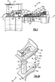
Figure 2A illustrates one such article, namely anairfoil 60.Figure 2B illustrates theairfoil 60, with a portion cut away. For instance, theairfoil 60 can be a turbine vane, as represented at 60a inFigure 1 , or a compressor vane, as represented at 60b inFigure 1 . In this example, theairfoil 60 is a static vane. As will be appreciated, although the examples herein are described in the context of a vane, this disclosure is not limited to vanes, and the examples may also be applicable to blades or other airfoils that are exposed to high temperatures. - The
airfoil 60 includes a first orouter end section 62, a second orinner end section 64, and anairfoil section 66 that spans in a longitudinal direction between a firstradial end 66a at thefirst end section 62 and a secondradial end 66b at thesecond end section 64. The longitudinal direction is also the radial direction in theengine 20 with regard to the engine central axis A. Theairfoil section 66 defines an airfoil profile (AP), which is the peripheral shape of theairfoil section 66 when viewed in a radial direction. For example, the airfoil profile (AP) has a wing-like shape that provides a reaction force via Bernoulli's principle with regard to flow over theairfoil section 66. The full or complete airfoil profile (AP) generally includes a leading end (LE), a trailing end (TE), a pressure side (PS), and a suction side (SS). For example, the leading end (LE) is the region of the airfoil profile (AP) that includes a leading edge of the airfoil profile (AP), and the trailing end (TE) is the region of the airfoil profile that includes a trailing edge. The leading edge may be the portion of the airfoil profile (AP) that first contacts air or the foremost edge of the airfoil profile (AP). The trailing edge may be the portion of the airfoil profile (AP) that last contacts air or the aftmost edge of the airfoil profile (AP). For a variable vane, the leading edge may shift, depending on the orientation of the vane. - The
airfoil section 66 may be hollow and include one or moreinternal cavities 68. The internal cavity orcavities 68 may be provided with cooling bleed air from the compressor section 24 of theengine 20, to cool theairfoil 60. In this example of a static vane, and theend sections 62/64 includerespective platforms 70. Together, theplatforms 70 provide the inner and outer bounds of the core gas path. Alternatively, for a variable vane, the end sections may have aerodynamic geometries without platforms; or for a blade, theairfoil 60 may include only an inner end section. - The
airfoil section 66 is formed of anairfoil structure 72 and aceramic airfoil piece 74 that is adjacent theairfoil structure 72. In this example, theairfoil structure 72 defines the suction side (SS), the pressure side (PS), and the trailing end (TE) of the airfoil profile (AP), and theceramic airfoil piece 74 defines the leading end (LE), or at least a portion thereof. As will be appreciated, although theceramic airfoil piece 74 in the illustrated example defines the leading end (LE), theceramic airfoil piece 74 may additionally or alternatively define the pressure side (PS), the suction side (SS), and/or the trailing end (TE), or additional ceramic airfoil pieces may be used to form the pressure side (PS), the suction side (SS), and/or the trailing end (TE). - Referring also to a sectioned view of the
ceramic airfoil piece 74 inFigure 3 , theceramic airfoil piece 74 includes anexterior wall 76 and aninterior wall 78. For example, the exterior surface (E1) ofexterior wall 76 is directly exposed in the core gas path, and the outside surface (E2) of theinterior wall 78 is not exposed in the core gas path. The outside surface (E2) of theinterior wall 78, which is an axial face, is located adjacent a forwardaxial face 72a of theairfoil structure 72. Theexterior wall 76 and theinterior wall 78 generally circumscribe acore passage 68a through theceramic airfoil piece 74, which is one of thepassages 68 of theairfoil section 66. Thecore passage 68a is generally a radially elongated passage with at least one open end that receives cooling bleed air through either the inner orouter end sections 62/64. - The
exterior wall 76 includes inner andouter wall portions 76a/76b. In this example, the inner andouter wall portions 76a/76b are both connected with theinterior wall 78. Theexterior wall 76 includes aninternal cooling circuit 80 defined between the inner andouter wall portions 76a/76b. For instance, theinternal cooling circuit 80 is a passage or series of interconnected passages within theexterior wall 76. - The
interior wall portion 76a includes a plurality ofinlet holes 76c. Eachinlet hole 76c opens at one end thereof to thecore cavity 68a and opens at an opposed end thereof to theinternal cooling circuit 80. Bleed air from thecore cavity 68a is fed through the inlet holes 76c and may impinge on theouter wall portion 76b, to cool theouter wall portion 76b. Theouter wall portion 76b includes a plurality ofoutlet holes 76d that open on one end thereof to theinternal cooling circuit 80 and open on another end thereof to the exterior surface (E1) of theouter wall portion 76b. The bleed air in theinternal cooling circuit 80 is discharged through theoutlet holes 76d, to provide film cooling over the exterior surface of theouter wall portion 76b. As an example, the bleed air is fed into theinternal cooling circuit 80 exclusively through the inlet holes 76c. That is, theinternal cooling circuit 80 is otherwise sealed. - In this example, the inner and
outer wall portions 76a/76b include a plurality of flow guides 82 that project into the passage of theinternal cooling circuit 80. For instance, the flow guides 82 are protrusions that project from either the inner orouter wall portions 76a/76b toward the other of the inner orouter wall portions 76a/76b. As also shown in the view ofFigure 4 , the flow guides 82 are separated byvalleys 84. In this example, the flow guides 82 are disposed in a pattern ofrows 82a. For example, therows 82a may be substantially parallel. The flow guides 82 serve to facilitate distribution and mixing of the bleed air in theinternal cooling circuit 80 to enhance cooling effectiveness. -
Figure 5A illustrates a modified example of aceramic airfoil piece 174. In this disclosure like reference numerals designate like elements where appropriate and reference numerals with the additional of one-hundred or multiples thereof designate modified elements that are understood to incorporate the same features or benefits of the corresponding elements. In this example, only theouter wall portion 176b includes flow guides 182 that project into the passage of theinternal cooling circuit 180. Theinner wall portion 176a includes no flow guides. As shown inFigure 5B , the flow guides 182 are discrete protrusions that are staggered along the radial direction (R). -
Figure 6A illustrates another modified example of a ceramic airfoil piece 274. In this example, only theinner wall portion 276a includes flow guides 282 that project into the passage of theinternal cooling circuit 280. The outer wall portion 276b includes no flow guides. As shown inFigure 6B , the flow guides 282 in this example are radially elongated ridges. As will be appreciated, a further modification may include a combination of discrete protrusions and ridges in a pattern. -
Figure 7 illustrates another modified example of a ceramic airfoil piece 374, which is similar to ceramic airfoil piece 274. In this example though, only theouter wall portion 376b includes flow guides 382 that project into the passage of theinternal cooling circuit 380. Theinner wall portion 376a includes no flow guides. Similar to the flow guides 282, the flow guides 382 are radially elongated ridges. -
Figure 8 illustrates another modified example of a ceramic airfoil piece 474. In this example, only theinner wall portion 476a includes flow guides 482 that project into the passage of theinternal cooling circuit 480. Theouter wall portion 476b includes no flow guides. Similar to the flow guides 182, the flow guides 482 are radially staggered discrete protrusions. - In each of the prior examples, the flow guides 82/182/282/382/482 extend from one of the wall portions but are disconnected or disjointed from the opposite wall portion. For instance, the tip ends of the protrusions are not attached to the opposite wall portion. This disconnection facilitates management of thermal stress in the ceramic airfoil piece. For instance, due to thermal gradients, the inner and outer wall portions may thermally expand/contract differently. By disconnecting the flow guides, the differential thermal expansion/contraction may facilitate reduction of thermal stresses between the inner and outer wall portions because the inner and outer wall portions do not restrict each other. In the examples that follow, the flow guides are connected to both the inner and outer wall portions, and thus tie the inner and outer wall portions together.
-
Figure 9 illustrates another modified example of a ceramic airfoil piece 574. In this example, the flow guides 582 are connected to both the inner andouter wall portions 576a/576b and span across the passage of theinternal cooling circuit 580. Similar to the flow guides 182, the flow guides 582 are discrete elements that are radially staggered. -
Figure 10 illustrates another modified example of aceramic airfoil piece 674. In this example, the flow guides 682 are connected to both the inner andouter wall portions 676a/676b and span across the passage of theinternal cooling circuit 680. Similar to the flow guides 282, the flow guides 682 are radially elongated. -
Figure 11 illustrates another modified example of aceramic airfoil piece 774. In this example, there are no flow guides in theinternal cooling circuit 780. -
Figure 12 illustrates another exampleceramic airfoil piece 1074. In this example, theinner wall portion 1076a is solid and continuous, and thus isolates thecore cavity 68a from theinternal cooling circuit 1080. Bleed air may be fed into theinternal cooling circuit 1080 from either the inner or outer radial end of theceramic airfoil piece 1074. Thecore cavity 68a may receive no bleed air or may receive a separate stream of bleed air from either the inner or outer radial end of theceramic airfoil piece 1074. - The
outer wall portion 1076b includes a plurality ofoutlet holes 1076c that open on one end thereof to theinternal cooling circuit 1080 and open on another end thereof to the exterior surface (E1) of theouter wall portion 1076b. The bleed air in theinternal cooling circuit 1080 is discharged through theoutlet holes 1076c, to provide film cooling over the exterior surface (E1) of theouter wall portion 1076b. As an example, the bleed air is fed into theinternal cooling circuit 1080 exclusively from either the inner or outer radial end of theceramic airfoil piece 1074. - In this example, the
outer wall portion 1076b includes a plurality offlow guides 1082a that project into the passage of theinternal cooling circuit 1080. For instance, as also shown in the views inFigures 13A and 13B , theflow guides 1082a are discrete protrusions that project from theouter wall portion 1076b toward theinner wall portion 1076a. As an example, the flow guides 1082a may be arranged in patterned rows such that bleed air flows around the flow guides 1082a. - The
inner wall portion 1076a includes a plurality offlow dimples 1082b, which are valleys or recesses in theinner wall portion 1076a. In this example, the flow guides 1082a project into the flow dimples 1082b, and thus form a circuitous passage there between. The engagement offlow guides 1082a with the flow dimples 1082b also serves to lock the inner andouter wall portions 1076a/1076b together, yet allow for thermal expansion/contraction differences. For instance, the inner andouter wall portions 1076a/1076b may thermally expand/contract differently. The flow guides 1082a are not rigidly attached with the flow dimples 1082b and thus permit relative thermal movement to facilitate reduction of thermal stresses between the inner andouter wall portions 1076a/1076b. However, since the flow guides 1082a are in close proximity to the flow dimples 1082b, the flow guides 1082a may contact the flow dimples 1082b if there is a relatively large thermal expansion or contraction difference, thus limiting thermal movement. -
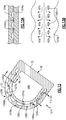
Figure 14 illustrates an airfoil comprising a ceramic airfoil piece 1174 with a portion cut away, in accordance with the present invention. In this disclosure, like reference numerals designate like elements where appropriate and reference numerals with the addition of one-hundred or multiples thereof designate modified elements that are understood to incorporate the same features and benefits of the corresponding elements. Theexterior wall 1176 includes inner and outer wall portions 1176a/1176b that define theinternal cooling circuit 1180 there between.Internal ribs 1184 connect the inner wall portion 1176a to theouter wall portion 1176b and definecircuitous circuit passages 1192 of theinternal cooling circuit 1180. - For instance, the
internal ribs 1184 may form one or more of several different types ofpassages 1192. For instance, thepassages 1192 may include one or moremanifold circuit passages 1192a that each feed two or more branch circuit passages. In the illustrated example, a serpentinebranch circuit passage 1192b-1 extends off of themanifold circuit passage 1192a. A block or linebranch circuit passage 1192b-2 also extends off of another portion of themanifold circuit passage 1192a. Thepassages 1192 may additionally or alternatively include one or more loop/impingement passages 1192c.Outlet holes 1176d are located at or near the ends of thebranch circuit passages 1192b-1/1192b-2. Theoutlet holes 1176d serve as a pressure dump to urge the bleed air flow (F1) to flow to the respectivebranch circuit passages 1192b-1/1192b-2. - The
internal cooling circuit 1180 also includes one or more of several different types of theinternal ribs 1184. In accordance with the present invention, a firstinternal rib 1184a includes animpingement orifice 1194. Theimpingement orifice 1194 opens toward animpingement face 1184b of a secondinternal rib 1184c such that bleed air flow (F1) impinges upon theimpingement face 1184b. The bleed air flow (F1) flows along the surface of the secondinternal rib 1184c and around the ends of therib 1184c. Therib 1184c is in animpingement passage 1192c, with anoutlet hole 1176d of the exterior wall (1176), opposite therib 1184c. Theoutlet hole 1176d serves as a pressure dump to urge the bleed air flow (F1) to flow around therib 1184c. - The
internal cooling circuit 1180 may be configured with the different types ofpassages 1192 andinternal ribs 1184, depending on the cooling requirements at particular locations on the ceramic airfoil piece 1174. For instance, the bleed air in the serpentinebranch circuit passage 1192b-1 or in aloop passage 1192c for impingement would pick up more heat than the bleed air in the blockbranch circuit passage 1192b-2, but the bleed air discharged from the serpentinebranch circuit passage 1192b-1 orloop passage 1192c would be at a lower pressure (for film cooling) than the bleed air discharged from the blockbranch circuit passage 1192b-2. - Should the
ceramic airfoil piece 74/174/274/374/474/574/674/774/1074/1174 require replacement, theairfoil 60 can be disassembled, theceramic airfoil piece 74/174/274/374/474/574/674/774/1074/1174 can be replaced with a new one, and theairfoil 60 can be reassembled. Accordingly, theceramic airfoil piece 74/174/274/374/474/574/674/774/1074/1174 can be produced individually as a new article fororiginal airfoils 60 or as an individual replacement article for an existing airfoil. - The ceramic from which the
ceramic airfoil piece 74/174/274/374/474/574/674/774/1074/1174 is formed may include, but is not limited to, oxides, carbides, nitrides, borides, silicides, and combinations thereof. A ceramic is a compound of metallic or metalloid elements bonded with nonmetallic elements or metalloid elements primarily in ionic or covalent bonds. In further examples, the ceramic is a monolithic ceramic or a ceramic matrix composite (CMC). For example, a monolithic ceramic is composed of a single, homogenous ceramic material. In comparison, a composite is composed of two or more materials that are individually easily distinguishable. A CMC has a reinforcement phase, such as ceramic or carbon fibers, dispersed in a ceramic matrix formed of oxides, carbides, nitrides, borides, silicides, or combinations thereof. - The
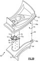
ceramic airfoil piece 74/174/274/374/474/574/674/774/1074/1174, or other turbine engine articles such as but not limited to blade outer air seals, platforms or end walls, may be fabricated using a sacrificial core processing technique. The processing technique is depicted inFigure 15 . The method of fabrication ,which is not claimed by the the present invention, may include wrappingpreceramic layers 96a around a firstsacrificial core element 98a. Thepreceramic layers 96a will form an inner wall portion as described herein and the firstsacrificial core element 98a will form thecore cavity 68a of the ceramic airfoil piece. A secondsacrificial core element 98b is provided on thepreceramic layers 96a. The secondsacrificial core element 98b will form the internal cooling circuit and any negative features, such as the flow dimples. Preceramic layers 96b are built up around secondsacrificial core element 98b. Thepreceramic layers 96b will form the flow guides or any positive features in the internal cooling circuit. Additionalpreceramic layers 96c are arranged around, and encompass, the entire structure. Thepreceramic layers 96c will form the outer wall portion and the interior wall of the ceramic airfoil piece. Once built, the structure may be treated to convert thepreceramic layers 96a/96b/96c to ceramic and to remove thesacrificial core elements 98a/98b, leaving thecore cavity 68a and internal cooling circuit. - For example, the treatment of the
preceramic layers 96a/96b/96c may include one or more thermal treatments. The thermal treatments convert thepreceramic layers 96a/96b/96c to ceramic and may also serve as a thermal treatment to remove thesacrificial core elements 98a/98b. Alternatively, thesacrificial core elements 98a/98b may be chemically removed. Although not limited, thelayers 96a/96b/96c may be fiber layers that are impregnated with a preceramic polymer, and thesacrificial core elements 98a/98b may be carbon elements. - Although a combination of features is shown in the illustrated examples, not all of them need to be combined to realize the benefits of various embodiments of this disclosure. In other words, a system designed according to an embodiment of this disclosure will not necessarily include all of the features shown in any one of the Figures or all of the portions schematically shown in the Figures. Moreover, selected features of one example embodiment may be combined with selected features of other example embodiments.
- The preceding description is exemplary rather than limiting in nature. Variations and modifications to the disclosed examples may become apparent to those skilled in the art that do not necessarily depart from this disclosure. The scope of legal protection given to this disclosure can only be determined by studying the following claims.
Claims (13)
- An airfoil (60) for a gas turbine engine (20) comprising an airfoil section (66) having radially inner and outer ends (66a, 66b) and defining an airfoil profile (AP) having a leading end (LE), a trailing end (TE), a suction side (SS), and a pressure side (PS), the airfoil section (66) including a ceramic airfoil piece (1174) that defines a portion of the airfoil profile (AP), the ceramic airfoil piece (1174) including an exterior wall (1176) having an internal cooling circuit (1180), wherein the exterior wall (1176) includes inner and outer wall portions (1176a, 1176b) that define the internal cooling circuit (1180) there between; characterised in that
the exterior wall (1176) includes a first internal rib (1184a) and a second internal rib (1184c) that connect the inner wall portion (1176a) to the outer wall portion (1176b) and define a circuitous circuit passages (1192) of the internal cooling circuit (1180) within the exterior wall (1176), the first internal rib (1184a) including an impingement orifice (1194) that opens toward an impingement face (1184b) of the second internal rib (1184c), and the exterior wall (1176) includes a cooling hole (1176d) on an opposite side of the second internal rib (1184c) from the impingement face (1184b). - The airfoil as recited in claim 1, wherein the ceramic airfoil piece (1174) includes a core cavity (68a), and a plurality of inlet holes (76c) that open at one end thereof to the core cavity (68a) and open at another end thereof to the internal cooling circuit (1180).
- The airfoil as recited in claim 1 or 2, wherein the exterior wall (1176) includes a plurality of outlet holes (76d) that open on one end thereof to the internal cooling circuit (1180) and open on another end thereof to an exterior surface of the exterior wall (1176).
- The airfoil as recited in claim 1, 2 or 3, wherein at least one of the inner or outer wall portions (1176a, 1176b) includes a plurality of flow guides that project into the passage toward the other of the inner or outer wall portions (1176a, 1176b).
- The airfoil as recited in claim 4, wherein the flow guides are radially elongated ridges.
- The airfoil as recited in claim 4 or 5, wherein the flow guides are staggered in a radial direction.
- The airfoil as recited in claim 1, 2 or 3, further comprising a plurality of flow guides that span across the passage (1192) and that are connected on opposed ends to the inner and outer wall portions (1176a, 1176b).
- The airfoil as recited in claim 7, wherein the flow guides are radially elongated.
- The airfoil as recited in claim 7 or 8, wherein the flow guides are staggered in a radial direction.
- The airfoil as recited in any preceding claim, wherein the ceramic airfoil piece (1174) defines the leading end (LE) of the airfoil profile (AP).
- The airfoil as recited in any preceding claim, wherein the ceramic airfoil piece (1174) includes a/the core cavity (68a), and the core cavity (68a) is isolated from the internal cooling circuit (1180).
- The airfoil as recited in any of claims 1 to 3, 10 and 11, wherein at least one of the inner or outer wall portions (1176a, 1176b) includes a plurality of flow guides that project into the passage (1192) toward the other of the inner or outer wall portions (1176a, 1176b), the other of the inner or outer wall portions (1176a, 1176b) including flow dimples (1082b) that border the passage (1192).
- The airfoil of claim 12, wherein the flow guides (1082a) project into the flow dimples (1082b).
Applications Claiming Priority (1)
| Application Number | Priority Date | Filing Date | Title |
|---|---|---|---|
| US15/354,093 US10677079B2 (en) | 2016-11-17 | 2016-11-17 | Airfoil with ceramic airfoil piece having internal cooling circuit |
Publications (2)
| Publication Number | Publication Date |
|---|---|
| EP3323997A1 EP3323997A1 (en) | 2018-05-23 |
| EP3323997B1 true EP3323997B1 (en) | 2021-06-02 |
Family
ID=60387929
Family Applications (1)
| Application Number | Title | Priority Date | Filing Date |
|---|---|---|---|
| EP17202345.9A Active EP3323997B1 (en) | 2016-11-17 | 2017-11-17 | Airfoil with ceramic airfoil piece having internal cooling circuit |
Country Status (2)
| Country | Link |
|---|---|
| US (1) | US10677079B2 (en) |
| EP (1) | EP3323997B1 (en) |
Families Citing this family (6)
| Publication number | Priority date | Publication date | Assignee | Title |
|---|---|---|---|---|
| US10370983B2 (en) * | 2017-07-28 | 2019-08-06 | Rolls-Royce Corporation | Endwall cooling system |
| US11255343B2 (en) | 2018-02-02 | 2022-02-22 | General Electric Company | Engine systems and methods |
| US10822985B2 (en) * | 2018-08-29 | 2020-11-03 | Raytheon Technologies Corporation | Internal cooling circuit for blade outer air seal formed of laminate |
| US11753944B2 (en) * | 2018-11-09 | 2023-09-12 | Raytheon Technologies Corporation | Airfoil with wall that tapers in thickness |
| JP6666500B1 (en) * | 2019-03-29 | 2020-03-13 | 三菱重工業株式会社 | High temperature component and method of manufacturing high temperature component |
| US11560803B1 (en) | 2021-11-05 | 2023-01-24 | General Electric Company | Component with cooling passage for a turbine engine |
Family Cites Families (62)
| Publication number | Priority date | Publication date | Assignee | Title |
|---|---|---|---|---|
| US3215511A (en) | 1962-03-30 | 1965-11-02 | Union Carbide Corp | Gas turbine nozzle vane and like articles |
| US4137008A (en) | 1977-09-21 | 1979-01-30 | The United States Of America As Represented By The Secretary Of The Navy | Adjustable blowing slot for circulation control airfoil |
| US4384452A (en) * | 1978-10-26 | 1983-05-24 | Rice Ivan G | Steam-cooled blading with steam thermal barrier for reheat gas turbine combined with steam turbine |
| US4835958A (en) * | 1978-10-26 | 1989-06-06 | Rice Ivan G | Process for directing a combustion gas stream onto rotatable blades of a gas turbine |
| US4247259A (en) | 1979-04-18 | 1981-01-27 | Avco Corporation | Composite ceramic/metallic turbine blade and method of making same |
| DE3110098C2 (en) | 1981-03-16 | 1983-03-17 | MTU Motoren- und Turbinen-Union München GmbH, 8000 München | Turbine guide vane for gas turbine engines |
| JPS59200001A (en) | 1983-04-28 | 1984-11-13 | Toshiba Corp | Gas turbine blade |
| JPS6166802A (en) | 1984-09-10 | 1986-04-05 | Mitsubishi Heavy Ind Ltd | Turbine blade of gas turbine |
| US4914794A (en) | 1986-08-07 | 1990-04-10 | Allied-Signal Inc. | Method of making an abradable strain-tolerant ceramic coated turbine shroud |
| US5295530A (en) * | 1992-02-18 | 1994-03-22 | General Motors Corporation | Single-cast, high-temperature, thin wall structures and methods of making the same |
| JPH05321602A (en) | 1992-05-25 | 1993-12-07 | Toshiba Corp | Gas turbine rotor blade |
| DE4238369C2 (en) | 1992-11-13 | 1996-09-26 | Mtu Muenchen Gmbh | Component made of a metallic base substrate with a ceramic coating |
| US5419971A (en) | 1993-03-03 | 1995-05-30 | General Electric Company | Enhanced thermal barrier coating system |
| US5358379A (en) | 1993-10-27 | 1994-10-25 | Westinghouse Electric Corporation | Gas turbine vane |
| US5538380A (en) | 1994-06-27 | 1996-07-23 | Solar Turbines Incorporated | Metallic nut for use with ceramic threads |
| US5558922A (en) | 1994-12-28 | 1996-09-24 | General Electric Company | Thick thermal barrier coating having grooves for enhanced strain tolerance |
| US5634771A (en) | 1995-09-25 | 1997-06-03 | General Electric Company | Partially-metallic blade for a gas turbine |
| US6102656A (en) | 1995-09-26 | 2000-08-15 | United Technologies Corporation | Segmented abradable ceramic coating |
| US5951892A (en) | 1996-12-10 | 1999-09-14 | Chromalloy Gas Turbine Corporation | Method of making an abradable seal by laser cutting |
| US6224963B1 (en) | 1997-05-14 | 2001-05-01 | Alliedsignal Inc. | Laser segmented thick thermal barrier coatings for turbine shrouds |
| US6000906A (en) | 1997-09-12 | 1999-12-14 | Alliedsignal Inc. | Ceramic airfoil |
| US6200092B1 (en) | 1999-09-24 | 2001-03-13 | General Electric Company | Ceramic turbine nozzle |
| US6316078B1 (en) | 2000-03-14 | 2001-11-13 | The United States Of America As Represented By The Administrator Of The National Aeronautics And Space Administration | Segmented thermal barrier coating |
| US6514046B1 (en) * | 2000-09-29 | 2003-02-04 | Siemens Westinghouse Power Corporation | Ceramic composite vane with metallic substructure |
| US6627019B2 (en) * | 2000-12-18 | 2003-09-30 | David C. Jarmon | Process for making ceramic matrix composite parts with cooling channels |
| US6846574B2 (en) | 2001-05-16 | 2005-01-25 | Siemens Westinghouse Power Corporation | Honeycomb structure thermal barrier coating |
| US6543996B2 (en) * | 2001-06-28 | 2003-04-08 | General Electric Company | Hybrid turbine nozzle |
| US6703137B2 (en) | 2001-08-02 | 2004-03-09 | Siemens Westinghouse Power Corporation | Segmented thermal barrier coating and method of manufacturing the same |
| US6554563B2 (en) * | 2001-08-13 | 2003-04-29 | General Electric Company | Tangential flow baffle |
| US6709230B2 (en) | 2002-05-31 | 2004-03-23 | Siemens Westinghouse Power Corporation | Ceramic matrix composite gas turbine vane |
| US7080971B2 (en) | 2003-03-12 | 2006-07-25 | Florida Turbine Technologies, Inc. | Cooled turbine spar shell blade construction |
| EP1489264A1 (en) | 2003-06-18 | 2004-12-22 | Siemens Aktiengesellschaft | Blade consisting of moduls |
| US7494557B1 (en) * | 2004-01-30 | 2009-02-24 | Sandia Corporation | Method of using sacrificial materials for fabricating internal cavities in laminated dielectric structures |
| US7104756B2 (en) | 2004-08-11 | 2006-09-12 | United Technologies Corporation | Temperature tolerant vane assembly |
| US7435058B2 (en) | 2005-01-18 | 2008-10-14 | Siemens Power Generation, Inc. | Ceramic matrix composite vane with chordwise stiffener |
| US7326030B2 (en) | 2005-02-02 | 2008-02-05 | Siemens Power Generation, Inc. | Support system for a composite airfoil in a turbine engine |
| US7316539B2 (en) | 2005-04-07 | 2008-01-08 | Siemens Power Generation, Inc. | Vane assembly with metal trailing edge segment |
| US7452182B2 (en) * | 2005-04-07 | 2008-11-18 | Siemens Energy, Inc. | Multi-piece turbine vane assembly |
| US7789621B2 (en) * | 2005-06-27 | 2010-09-07 | Rolls-Royce North American Technologies, Inc. | Gas turbine engine airfoil |
| US7329087B2 (en) | 2005-09-19 | 2008-02-12 | General Electric Company | Seal-less CMC vane to platform interfaces |
| US7520725B1 (en) | 2006-08-11 | 2009-04-21 | Florida Turbine Technologies, Inc. | Turbine airfoil with near-wall leading edge multi-holes cooling |
| US9039358B2 (en) | 2007-01-03 | 2015-05-26 | United Technologies Corporation | Replaceable blade outer air seal design |
| US20100136258A1 (en) | 2007-04-25 | 2010-06-03 | Strock Christopher W | Method for improved ceramic coating |
| US8182208B2 (en) | 2007-07-10 | 2012-05-22 | United Technologies Corp. | Gas turbine systems involving feather seals |
| US7963745B1 (en) | 2007-07-10 | 2011-06-21 | Florida Turbine Technologies, Inc. | Composite turbine blade |
| US8202043B2 (en) | 2007-10-15 | 2012-06-19 | United Technologies Corp. | Gas turbine engines and related systems involving variable vanes |
| US8079806B2 (en) | 2007-11-28 | 2011-12-20 | United Technologies Corporation | Segmented ceramic layer for member of gas turbine engine |
| GB2458685B (en) | 2008-03-28 | 2010-05-12 | Rolls Royce Plc | An article formed from a composite material |
| US8251651B2 (en) | 2009-01-28 | 2012-08-28 | United Technologies Corporation | Segmented ceramic matrix composite turbine airfoil component |
| US8109724B2 (en) | 2009-03-26 | 2012-02-07 | United Technologies Corporation | Recessed metering standoffs for airfoil baffle |
| US8585368B2 (en) | 2009-04-16 | 2013-11-19 | United Technologies Corporation | Hybrid structure airfoil |
| US8366392B1 (en) | 2009-05-06 | 2013-02-05 | Florida Turbine Technologies, Inc. | Composite air cooled turbine rotor blade |
| US8197211B1 (en) | 2009-09-25 | 2012-06-12 | Florida Turbine Technologies, Inc. | Composite air cooled turbine rotor blade |
| US8506243B2 (en) | 2009-11-19 | 2013-08-13 | United Technologies Corporation | Segmented thermally insulating coating |
| US9739157B2 (en) | 2013-03-12 | 2017-08-22 | Rolls-Royce Corporation | Cooled ceramic matrix composite airfoil |
| US10253634B2 (en) * | 2013-06-04 | 2019-04-09 | United Technologies Corporation | Gas turbine engine airfoil trailing edge suction side cooling |
| DE102013219774A1 (en) | 2013-09-30 | 2015-04-02 | MTU Aero Engines AG | Shovel for a gas turbine |
| US10221701B2 (en) | 2013-11-22 | 2019-03-05 | United Technologies Corporation | Multi-material turbine airfoil |
| US20150152737A1 (en) * | 2013-12-02 | 2015-06-04 | George Liang | Turbine blade with near wall microcircuit edge cooling |
| US10107117B2 (en) | 2014-09-30 | 2018-10-23 | United Technologies Corporation | Airfoil assembly with spacer and tie-spar |
| US9896954B2 (en) * | 2014-10-14 | 2018-02-20 | Rolls-Royce Corporation | Dual-walled ceramic matrix composite (CMC) component with integral cooling and method of making a CMC component with integral cooling |
| US10408084B2 (en) | 2015-03-02 | 2019-09-10 | Rolls-Royce North American Technologies Inc. | Vane assembly for a gas turbine engine |
-
2016
- 2016-11-17 US US15/354,093 patent/US10677079B2/en active Active
-
2017
- 2017-11-17 EP EP17202345.9A patent/EP3323997B1/en active Active
Non-Patent Citations (1)
| Title |
|---|
| None * |
Also Published As
| Publication number | Publication date |
|---|---|
| US20180135446A1 (en) | 2018-05-17 |
| US10677079B2 (en) | 2020-06-09 |
| EP3323997A1 (en) | 2018-05-23 |
Similar Documents
| Publication | Publication Date | Title |
|---|---|---|
| EP3323997B1 (en) | Airfoil with ceramic airfoil piece having internal cooling circuit | |
| US10301964B2 (en) | Baffle with flow augmentation feature | |
| EP3323612B1 (en) | Method for making ceramic turbine engine article | |
| US10837294B2 (en) | Multi-material turbine airfoil | |
| EP3335873B1 (en) | Gas turbine engine vane | |
| EP3342980B1 (en) | Airfoil with dual profile leading end | |
| EP3323991B1 (en) | Vane or blade with airfoil piece having radial seal | |
| EP3323979B1 (en) | Airfoil with panel having perimeter seal | |
| EP3323987B1 (en) | Airfoil having endwall panels and corresponding gas turbine engine | |
| EP3323993B1 (en) | Gas turbine airfoil pieces and feather seal | |
| EP3323981B1 (en) | Airfoil pieces secured with endwall section | |
| EP3617454B1 (en) | Variable heat transfer collector baffle | |
| EP3508693B1 (en) | Segregated cooling air passages for turbine vane | |
| US11788419B1 (en) | Airfoil leading edge venturi cooling passage | |
| EP4056811A1 (en) | Scalloped mateface seal arrangement for cmc platforms | |
| US11802487B1 (en) | Gas turbine engine stator vane formed of ceramic matrix composites and having attachment flanges | |
| EP3808940B1 (en) | Cmc airfoil for a gas turbine engine with cooling holes | |
| EP4353949A1 (en) | Gas turbine engine vane and spar combination with variable air flow path | |
| EP3324004B1 (en) | Airfoil with retention pocket holding airfoil piece | |
| US20180135444A1 (en) | Airfoil with retention pocket holding airfoil piece |
Legal Events
| Date | Code | Title | Description |
|---|---|---|---|
| PUAI | Public reference made under article 153(3) epc to a published international application that has entered the european phase |
Free format text: ORIGINAL CODE: 0009012 |
|
| STAA | Information on the status of an ep patent application or granted ep patent |
Free format text: STATUS: THE APPLICATION HAS BEEN PUBLISHED |
|
| AK | Designated contracting states |
Kind code of ref document: A1 Designated state(s): AL AT BE BG CH CY CZ DE DK EE ES FI FR GB GR HR HU IE IS IT LI LT LU LV MC MK MT NL NO PL PT RO RS SE SI SK SM TR |
|
| AX | Request for extension of the european patent |
Extension state: BA ME |
|
| STAA | Information on the status of an ep patent application or granted ep patent |
Free format text: STATUS: REQUEST FOR EXAMINATION WAS MADE |
|
| 17P | Request for examination filed |
Effective date: 20181123 |
|
| RBV | Designated contracting states (corrected) |
Designated state(s): AL AT BE BG CH CY CZ DE DK EE ES FI FR GB GR HR HU IE IS IT LI LT LU LV MC MK MT NL NO PL PT RO RS SE SI SK SM TR |
|
| STAA | Information on the status of an ep patent application or granted ep patent |
Free format text: STATUS: EXAMINATION IS IN PROGRESS |
|
| 17Q | First examination report despatched |
Effective date: 20200130 |
|
| GRAP | Despatch of communication of intention to grant a patent |
Free format text: ORIGINAL CODE: EPIDOSNIGR1 |
|
| STAA | Information on the status of an ep patent application or granted ep patent |
Free format text: STATUS: GRANT OF PATENT IS INTENDED |
|
| INTG | Intention to grant announced |
Effective date: 20210112 |
|
| RAP1 | Party data changed (applicant data changed or rights of an application transferred) |
Owner name: RAYTHEON TECHNOLOGIES CORPORATION |
|
| GRAS | Grant fee paid |
Free format text: ORIGINAL CODE: EPIDOSNIGR3 |
|
| GRAA | (expected) grant |
Free format text: ORIGINAL CODE: 0009210 |
|
| STAA | Information on the status of an ep patent application or granted ep patent |
Free format text: STATUS: THE PATENT HAS BEEN GRANTED |
|
| REG | Reference to a national code |
Ref country code: CH Ref legal event code: EP |
|
| AK | Designated contracting states |
Kind code of ref document: B1 Designated state(s): AL AT BE BG CH CY CZ DE DK EE ES FI FR GB GR HR HU IE IS IT LI LT LU LV MC MK MT NL NO PL PT RO RS SE SI SK SM TR |
|
| REG | Reference to a national code |
Ref country code: GB Ref legal event code: FG4D |
|
| REG | Reference to a national code |
Ref country code: AT Ref legal event code: REF Ref document number: 1398607 Country of ref document: AT Kind code of ref document: T Effective date: 20210615 |
|
| REG | Reference to a national code |
Ref country code: IE Ref legal event code: FG4D |
|
| REG | Reference to a national code |
Ref country code: DE Ref legal event code: R096 Ref document number: 602017039590 Country of ref document: DE |
|
| REG | Reference to a national code |
Ref country code: LT Ref legal event code: MG9D |
|
| PG25 | Lapsed in a contracting state [announced via postgrant information from national office to epo] |
Ref country code: BG Free format text: LAPSE BECAUSE OF FAILURE TO SUBMIT A TRANSLATION OF THE DESCRIPTION OR TO PAY THE FEE WITHIN THE PRESCRIBED TIME-LIMIT Effective date: 20210902 Ref country code: HR Free format text: LAPSE BECAUSE OF FAILURE TO SUBMIT A TRANSLATION OF THE DESCRIPTION OR TO PAY THE FEE WITHIN THE PRESCRIBED TIME-LIMIT Effective date: 20210602 Ref country code: FI Free format text: LAPSE BECAUSE OF FAILURE TO SUBMIT A TRANSLATION OF THE DESCRIPTION OR TO PAY THE FEE WITHIN THE PRESCRIBED TIME-LIMIT Effective date: 20210602 Ref country code: LT Free format text: LAPSE BECAUSE OF FAILURE TO SUBMIT A TRANSLATION OF THE DESCRIPTION OR TO PAY THE FEE WITHIN THE PRESCRIBED TIME-LIMIT Effective date: 20210602 |
|
| REG | Reference to a national code |
Ref country code: NL Ref legal event code: MP Effective date: 20210602 |
|
| REG | Reference to a national code |
Ref country code: AT Ref legal event code: MK05 Ref document number: 1398607 Country of ref document: AT Kind code of ref document: T Effective date: 20210602 |
|
| PG25 | Lapsed in a contracting state [announced via postgrant information from national office to epo] |
Ref country code: GR Free format text: LAPSE BECAUSE OF FAILURE TO SUBMIT A TRANSLATION OF THE DESCRIPTION OR TO PAY THE FEE WITHIN THE PRESCRIBED TIME-LIMIT Effective date: 20210903 Ref country code: LV Free format text: LAPSE BECAUSE OF FAILURE TO SUBMIT A TRANSLATION OF THE DESCRIPTION OR TO PAY THE FEE WITHIN THE PRESCRIBED TIME-LIMIT Effective date: 20210602 Ref country code: RS Free format text: LAPSE BECAUSE OF FAILURE TO SUBMIT A TRANSLATION OF THE DESCRIPTION OR TO PAY THE FEE WITHIN THE PRESCRIBED TIME-LIMIT Effective date: 20210602 Ref country code: SE Free format text: LAPSE BECAUSE OF FAILURE TO SUBMIT A TRANSLATION OF THE DESCRIPTION OR TO PAY THE FEE WITHIN THE PRESCRIBED TIME-LIMIT Effective date: 20210602 Ref country code: PL Free format text: LAPSE BECAUSE OF FAILURE TO SUBMIT A TRANSLATION OF THE DESCRIPTION OR TO PAY THE FEE WITHIN THE PRESCRIBED TIME-LIMIT Effective date: 20210602 Ref country code: NO Free format text: LAPSE BECAUSE OF FAILURE TO SUBMIT A TRANSLATION OF THE DESCRIPTION OR TO PAY THE FEE WITHIN THE PRESCRIBED TIME-LIMIT Effective date: 20210902 |
|
| PG25 | Lapsed in a contracting state [announced via postgrant information from national office to epo] |
Ref country code: SM Free format text: LAPSE BECAUSE OF FAILURE TO SUBMIT A TRANSLATION OF THE DESCRIPTION OR TO PAY THE FEE WITHIN THE PRESCRIBED TIME-LIMIT Effective date: 20210602 Ref country code: SK Free format text: LAPSE BECAUSE OF FAILURE TO SUBMIT A TRANSLATION OF THE DESCRIPTION OR TO PAY THE FEE WITHIN THE PRESCRIBED TIME-LIMIT Effective date: 20210602 Ref country code: NL Free format text: LAPSE BECAUSE OF FAILURE TO SUBMIT A TRANSLATION OF THE DESCRIPTION OR TO PAY THE FEE WITHIN THE PRESCRIBED TIME-LIMIT Effective date: 20210602 Ref country code: RO Free format text: LAPSE BECAUSE OF FAILURE TO SUBMIT A TRANSLATION OF THE DESCRIPTION OR TO PAY THE FEE WITHIN THE PRESCRIBED TIME-LIMIT Effective date: 20210602 Ref country code: PT Free format text: LAPSE BECAUSE OF FAILURE TO SUBMIT A TRANSLATION OF THE DESCRIPTION OR TO PAY THE FEE WITHIN THE PRESCRIBED TIME-LIMIT Effective date: 20211004 Ref country code: ES Free format text: LAPSE BECAUSE OF FAILURE TO SUBMIT A TRANSLATION OF THE DESCRIPTION OR TO PAY THE FEE WITHIN THE PRESCRIBED TIME-LIMIT Effective date: 20210602 Ref country code: AT Free format text: LAPSE BECAUSE OF FAILURE TO SUBMIT A TRANSLATION OF THE DESCRIPTION OR TO PAY THE FEE WITHIN THE PRESCRIBED TIME-LIMIT Effective date: 20210602 Ref country code: CZ Free format text: LAPSE BECAUSE OF FAILURE TO SUBMIT A TRANSLATION OF THE DESCRIPTION OR TO PAY THE FEE WITHIN THE PRESCRIBED TIME-LIMIT Effective date: 20210602 Ref country code: EE Free format text: LAPSE BECAUSE OF FAILURE TO SUBMIT A TRANSLATION OF THE DESCRIPTION OR TO PAY THE FEE WITHIN THE PRESCRIBED TIME-LIMIT Effective date: 20210602 |
|
| REG | Reference to a national code |
Ref country code: DE Ref legal event code: R097 Ref document number: 602017039590 Country of ref document: DE |
|
| PLBE | No opposition filed within time limit |
Free format text: ORIGINAL CODE: 0009261 |
|
| STAA | Information on the status of an ep patent application or granted ep patent |
Free format text: STATUS: NO OPPOSITION FILED WITHIN TIME LIMIT |
|
| PG25 | Lapsed in a contracting state [announced via postgrant information from national office to epo] |
Ref country code: DK Free format text: LAPSE BECAUSE OF FAILURE TO SUBMIT A TRANSLATION OF THE DESCRIPTION OR TO PAY THE FEE WITHIN THE PRESCRIBED TIME-LIMIT Effective date: 20210602 |
|
| 26N | No opposition filed |
Effective date: 20220303 |
|
| PG25 | Lapsed in a contracting state [announced via postgrant information from national office to epo] |
Ref country code: AL Free format text: LAPSE BECAUSE OF FAILURE TO SUBMIT A TRANSLATION OF THE DESCRIPTION OR TO PAY THE FEE WITHIN THE PRESCRIBED TIME-LIMIT Effective date: 20210602 |
|
| PG25 | Lapsed in a contracting state [announced via postgrant information from national office to epo] |
Ref country code: MC Free format text: LAPSE BECAUSE OF FAILURE TO SUBMIT A TRANSLATION OF THE DESCRIPTION OR TO PAY THE FEE WITHIN THE PRESCRIBED TIME-LIMIT Effective date: 20210602 |
|
| REG | Reference to a national code |
Ref country code: CH Ref legal event code: PL |
|
| PG25 | Lapsed in a contracting state [announced via postgrant information from national office to epo] |
Ref country code: LU Free format text: LAPSE BECAUSE OF NON-PAYMENT OF DUE FEES Effective date: 20211117 Ref country code: IT Free format text: LAPSE BECAUSE OF FAILURE TO SUBMIT A TRANSLATION OF THE DESCRIPTION OR TO PAY THE FEE WITHIN THE PRESCRIBED TIME-LIMIT Effective date: 20210602 Ref country code: BE Free format text: LAPSE BECAUSE OF NON-PAYMENT OF DUE FEES Effective date: 20211130 |
|
| REG | Reference to a national code |
Ref country code: BE Ref legal event code: MM Effective date: 20211130 |
|
| PG25 | Lapsed in a contracting state [announced via postgrant information from national office to epo] |
Ref country code: LI Free format text: LAPSE BECAUSE OF NON-PAYMENT OF DUE FEES Effective date: 20211130 Ref country code: CH Free format text: LAPSE BECAUSE OF NON-PAYMENT OF DUE FEES Effective date: 20211130 |
|
| PG25 | Lapsed in a contracting state [announced via postgrant information from national office to epo] |
Ref country code: IE Free format text: LAPSE BECAUSE OF NON-PAYMENT OF DUE FEES Effective date: 20211117 |
|
| PG25 | Lapsed in a contracting state [announced via postgrant information from national office to epo] |
Ref country code: HU Free format text: LAPSE BECAUSE OF FAILURE TO SUBMIT A TRANSLATION OF THE DESCRIPTION OR TO PAY THE FEE WITHIN THE PRESCRIBED TIME-LIMIT; INVALID AB INITIO Effective date: 20171117 |
|
| P01 | Opt-out of the competence of the unified patent court (upc) registered |
Effective date: 20230520 |
|
| PG25 | Lapsed in a contracting state [announced via postgrant information from national office to epo] |
Ref country code: CY Free format text: LAPSE BECAUSE OF FAILURE TO SUBMIT A TRANSLATION OF THE DESCRIPTION OR TO PAY THE FEE WITHIN THE PRESCRIBED TIME-LIMIT Effective date: 20210602 |
|
| PGFP | Annual fee paid to national office [announced via postgrant information from national office to epo] |
Ref country code: GB Payment date: 20231019 Year of fee payment: 7 |
|
| PGFP | Annual fee paid to national office [announced via postgrant information from national office to epo] |
Ref country code: FR Payment date: 20231019 Year of fee payment: 7 Ref country code: DE Payment date: 20231019 Year of fee payment: 7 |