EP3323996A1 - Composant de moteur à turbine avec section de revêtement segmenté géométriquement et passage de refroidissement - Google Patents
Composant de moteur à turbine avec section de revêtement segmenté géométriquement et passage de refroidissement Download PDFInfo
- Publication number
- EP3323996A1 EP3323996A1 EP17202298.0A EP17202298A EP3323996A1 EP 3323996 A1 EP3323996 A1 EP 3323996A1 EP 17202298 A EP17202298 A EP 17202298A EP 3323996 A1 EP3323996 A1 EP 3323996A1
- Authority
- EP
- European Patent Office
- Prior art keywords
- coating
- cooling passage
- section
- cells
- turbine engine
- Prior art date
- Legal status (The legal status is an assumption and is not a legal conclusion. Google has not performed a legal analysis and makes no representation as to the accuracy of the status listed.)
- Granted
Links
- 239000011248 coating agent Substances 0.000 title claims abstract description 92
- 238000000576 coating method Methods 0.000 title claims abstract description 92
- 238000001816 cooling Methods 0.000 title claims abstract description 81
- 238000005538 encapsulation Methods 0.000 claims description 24
- 238000000034 method Methods 0.000 claims description 16
- 239000000919 ceramic Substances 0.000 claims description 5
- 238000004891 communication Methods 0.000 claims description 5
- 238000000151 deposition Methods 0.000 claims description 5
- 239000012530 fluid Substances 0.000 claims description 4
- 239000011247 coating layer Substances 0.000 description 11
- 229910010293 ceramic material Inorganic materials 0.000 description 10
- 229910045601 alloy Inorganic materials 0.000 description 6
- 239000000956 alloy Substances 0.000 description 6
- 239000000446 fuel Substances 0.000 description 6
- 239000000463 material Substances 0.000 description 6
- 230000001965 increasing effect Effects 0.000 description 5
- 238000003754 machining Methods 0.000 description 5
- 230000008569 process Effects 0.000 description 5
- 229910000990 Ni alloy Inorganic materials 0.000 description 4
- CMIHHWBVHJVIGI-UHFFFAOYSA-N gadolinium(iii) oxide Chemical compound [O-2].[O-2].[O-2].[Gd+3].[Gd+3] CMIHHWBVHJVIGI-UHFFFAOYSA-N 0.000 description 4
- 238000004519 manufacturing process Methods 0.000 description 4
- 230000004888 barrier function Effects 0.000 description 3
- 230000009467 reduction Effects 0.000 description 3
- 239000007921 spray Substances 0.000 description 3
- 229910000531 Co alloy Inorganic materials 0.000 description 2
- XEEYBQQBJWHFJM-UHFFFAOYSA-N Iron Chemical compound [Fe] XEEYBQQBJWHFJM-UHFFFAOYSA-N 0.000 description 2
- PXHVJJICTQNCMI-UHFFFAOYSA-N Nickel Chemical compound [Ni] PXHVJJICTQNCMI-UHFFFAOYSA-N 0.000 description 2
- MCMNRKCIXSYSNV-UHFFFAOYSA-N Zirconium dioxide Chemical compound O=[Zr]=O MCMNRKCIXSYSNV-UHFFFAOYSA-N 0.000 description 2
- 230000008901 benefit Effects 0.000 description 2
- 229910017052 cobalt Inorganic materials 0.000 description 2
- 239000010941 cobalt Substances 0.000 description 2
- GUTLYIVDDKVIGB-UHFFFAOYSA-N cobalt atom Chemical compound [Co] GUTLYIVDDKVIGB-UHFFFAOYSA-N 0.000 description 2
- 230000007613 environmental effect Effects 0.000 description 2
- 238000000227 grinding Methods 0.000 description 2
- 150000001247 metal acetylides Chemical class 0.000 description 2
- 229910052752 metalloid Inorganic materials 0.000 description 2
- 150000004767 nitrides Chemical class 0.000 description 2
- BASFCYQUMIYNBI-UHFFFAOYSA-N platinum Chemical compound [Pt] BASFCYQUMIYNBI-UHFFFAOYSA-N 0.000 description 2
- 229910021332 silicide Inorganic materials 0.000 description 2
- 238000005245 sintering Methods 0.000 description 2
- 230000003068 static effect Effects 0.000 description 2
- 229920000049 Carbon (fiber) Polymers 0.000 description 1
- 241000588731 Hafnia Species 0.000 description 1
- BQCADISMDOOEFD-UHFFFAOYSA-N Silver Chemical compound [Ag] BQCADISMDOOEFD-UHFFFAOYSA-N 0.000 description 1
- 238000005299 abrasion Methods 0.000 description 1
- 239000000654 additive Substances 0.000 description 1
- 230000000996 additive effect Effects 0.000 description 1
- PNEYBMLMFCGWSK-UHFFFAOYSA-N aluminium oxide Inorganic materials [O-2].[O-2].[O-2].[Al+3].[Al+3] PNEYBMLMFCGWSK-UHFFFAOYSA-N 0.000 description 1
- 238000013459 approach Methods 0.000 description 1
- 238000005219 brazing Methods 0.000 description 1
- 239000004917 carbon fiber Substances 0.000 description 1
- 238000005524 ceramic coating Methods 0.000 description 1
- 239000011153 ceramic matrix composite Substances 0.000 description 1
- 230000008859 change Effects 0.000 description 1
- 238000002485 combustion reaction Methods 0.000 description 1
- 150000001875 compounds Chemical class 0.000 description 1
- 230000006835 compression Effects 0.000 description 1
- 238000007906 compression Methods 0.000 description 1
- 238000012937 correction Methods 0.000 description 1
- 238000005336 cracking Methods 0.000 description 1
- 230000032798 delamination Effects 0.000 description 1
- 238000000280 densification Methods 0.000 description 1
- 238000005137 deposition process Methods 0.000 description 1
- 230000002708 enhancing effect Effects 0.000 description 1
- PCHJSUWPFVWCPO-UHFFFAOYSA-N gold Chemical compound [Au] PCHJSUWPFVWCPO-UHFFFAOYSA-N 0.000 description 1
- 229910052737 gold Inorganic materials 0.000 description 1
- 239000010931 gold Substances 0.000 description 1
- CJNBYAVZURUTKZ-UHFFFAOYSA-N hafnium(IV) oxide Inorganic materials O=[Hf]=O CJNBYAVZURUTKZ-UHFFFAOYSA-N 0.000 description 1
- 238000005495 investment casting Methods 0.000 description 1
- 229910052742 iron Inorganic materials 0.000 description 1
- 239000010410 layer Substances 0.000 description 1
- 239000011159 matrix material Substances 0.000 description 1
- 230000007246 mechanism Effects 0.000 description 1
- 238000002844 melting Methods 0.000 description 1
- 230000008018 melting Effects 0.000 description 1
- 229910052751 metal Inorganic materials 0.000 description 1
- 238000012986 modification Methods 0.000 description 1
- 230000004048 modification Effects 0.000 description 1
- MEFBJEMVZONFCJ-UHFFFAOYSA-N molybdate Chemical compound [O-][Mo]([O-])(=O)=O MEFBJEMVZONFCJ-UHFFFAOYSA-N 0.000 description 1
- 229910052759 nickel Inorganic materials 0.000 description 1
- 238000005240 physical vapour deposition Methods 0.000 description 1
- 229910052697 platinum Inorganic materials 0.000 description 1
- 239000011148 porous material Substances 0.000 description 1
- 230000002787 reinforcement Effects 0.000 description 1
- 230000004044 response Effects 0.000 description 1
- 229910052709 silver Inorganic materials 0.000 description 1
- 239000004332 silver Substances 0.000 description 1
- 239000002356 single layer Substances 0.000 description 1
- RUDFQVOCFDJEEF-UHFFFAOYSA-N yttrium(III) oxide Inorganic materials [O-2].[O-2].[O-2].[Y+3].[Y+3] RUDFQVOCFDJEEF-UHFFFAOYSA-N 0.000 description 1
Images
Classifications
-
- F—MECHANICAL ENGINEERING; LIGHTING; HEATING; WEAPONS; BLASTING
- F01—MACHINES OR ENGINES IN GENERAL; ENGINE PLANTS IN GENERAL; STEAM ENGINES
- F01D—NON-POSITIVE DISPLACEMENT MACHINES OR ENGINES, e.g. STEAM TURBINES
- F01D5/00—Blades; Blade-carrying members; Heating, heat-insulating, cooling or antivibration means on the blades or the members
- F01D5/12—Blades
- F01D5/28—Selecting particular materials; Particular measures relating thereto; Measures against erosion or corrosion
- F01D5/288—Protective coatings for blades
-
- F—MECHANICAL ENGINEERING; LIGHTING; HEATING; WEAPONS; BLASTING
- F01—MACHINES OR ENGINES IN GENERAL; ENGINE PLANTS IN GENERAL; STEAM ENGINES
- F01D—NON-POSITIVE DISPLACEMENT MACHINES OR ENGINES, e.g. STEAM TURBINES
- F01D9/00—Stators
- F01D9/02—Nozzles; Nozzle boxes; Stator blades; Guide conduits, e.g. individual nozzles
-
- F—MECHANICAL ENGINEERING; LIGHTING; HEATING; WEAPONS; BLASTING
- F01—MACHINES OR ENGINES IN GENERAL; ENGINE PLANTS IN GENERAL; STEAM ENGINES
- F01D—NON-POSITIVE DISPLACEMENT MACHINES OR ENGINES, e.g. STEAM TURBINES
- F01D11/00—Preventing or minimising internal leakage of working-fluid, e.g. between stages
- F01D11/08—Preventing or minimising internal leakage of working-fluid, e.g. between stages for sealing space between rotor blade tips and stator
- F01D11/12—Preventing or minimising internal leakage of working-fluid, e.g. between stages for sealing space between rotor blade tips and stator using a rubstrip, e.g. erodible. deformable or resiliently-biased part
- F01D11/122—Preventing or minimising internal leakage of working-fluid, e.g. between stages for sealing space between rotor blade tips and stator using a rubstrip, e.g. erodible. deformable or resiliently-biased part with erodable or abradable material
- F01D11/125—Preventing or minimising internal leakage of working-fluid, e.g. between stages for sealing space between rotor blade tips and stator using a rubstrip, e.g. erodible. deformable or resiliently-biased part with erodable or abradable material with a reinforcing structure
-
- F—MECHANICAL ENGINEERING; LIGHTING; HEATING; WEAPONS; BLASTING
- F01—MACHINES OR ENGINES IN GENERAL; ENGINE PLANTS IN GENERAL; STEAM ENGINES
- F01D—NON-POSITIVE DISPLACEMENT MACHINES OR ENGINES, e.g. STEAM TURBINES
- F01D25/00—Component parts, details, or accessories, not provided for in, or of interest apart from, other groups
- F01D25/08—Cooling; Heating; Heat-insulation
- F01D25/12—Cooling
-
- F—MECHANICAL ENGINEERING; LIGHTING; HEATING; WEAPONS; BLASTING
- F02—COMBUSTION ENGINES; HOT-GAS OR COMBUSTION-PRODUCT ENGINE PLANTS
- F02C—GAS-TURBINE PLANTS; AIR INTAKES FOR JET-PROPULSION PLANTS; CONTROLLING FUEL SUPPLY IN AIR-BREATHING JET-PROPULSION PLANTS
- F02C3/00—Gas-turbine plants characterised by the use of combustion products as the working fluid
- F02C3/04—Gas-turbine plants characterised by the use of combustion products as the working fluid having a turbine driving a compressor
-
- F—MECHANICAL ENGINEERING; LIGHTING; HEATING; WEAPONS; BLASTING
- F04—POSITIVE - DISPLACEMENT MACHINES FOR LIQUIDS; PUMPS FOR LIQUIDS OR ELASTIC FLUIDS
- F04D—NON-POSITIVE-DISPLACEMENT PUMPS
- F04D29/00—Details, component parts, or accessories
- F04D29/08—Sealings
- F04D29/083—Sealings especially adapted for elastic fluid pumps
-
- F—MECHANICAL ENGINEERING; LIGHTING; HEATING; WEAPONS; BLASTING
- F04—POSITIVE - DISPLACEMENT MACHINES FOR LIQUIDS; PUMPS FOR LIQUIDS OR ELASTIC FLUIDS
- F04D—NON-POSITIVE-DISPLACEMENT PUMPS
- F04D29/00—Details, component parts, or accessories
- F04D29/40—Casings; Connections of working fluid
- F04D29/52—Casings; Connections of working fluid for axial pumps
- F04D29/54—Fluid-guiding means, e.g. diffusers
- F04D29/541—Specially adapted for elastic fluid pumps
- F04D29/542—Bladed diffusers
-
- F—MECHANICAL ENGINEERING; LIGHTING; HEATING; WEAPONS; BLASTING
- F04—POSITIVE - DISPLACEMENT MACHINES FOR LIQUIDS; PUMPS FOR LIQUIDS OR ELASTIC FLUIDS
- F04D—NON-POSITIVE-DISPLACEMENT PUMPS
- F04D29/00—Details, component parts, or accessories
- F04D29/58—Cooling; Heating; Diminishing heat transfer
- F04D29/582—Cooling; Heating; Diminishing heat transfer specially adapted for elastic fluid pumps
-
- F—MECHANICAL ENGINEERING; LIGHTING; HEATING; WEAPONS; BLASTING
- F23—COMBUSTION APPARATUS; COMBUSTION PROCESSES
- F23R—GENERATING COMBUSTION PRODUCTS OF HIGH PRESSURE OR HIGH VELOCITY, e.g. GAS-TURBINE COMBUSTION CHAMBERS
- F23R3/00—Continuous combustion chambers using liquid or gaseous fuel
- F23R3/002—Wall structures
-
- F—MECHANICAL ENGINEERING; LIGHTING; HEATING; WEAPONS; BLASTING
- F05—INDEXING SCHEMES RELATING TO ENGINES OR PUMPS IN VARIOUS SUBCLASSES OF CLASSES F01-F04
- F05D—INDEXING SCHEME FOR ASPECTS RELATING TO NON-POSITIVE-DISPLACEMENT MACHINES OR ENGINES, GAS-TURBINES OR JET-PROPULSION PLANTS
- F05D2220/00—Application
- F05D2220/30—Application in turbines
- F05D2220/32—Application in turbines in gas turbines
-
- F—MECHANICAL ENGINEERING; LIGHTING; HEATING; WEAPONS; BLASTING
- F05—INDEXING SCHEMES RELATING TO ENGINES OR PUMPS IN VARIOUS SUBCLASSES OF CLASSES F01-F04
- F05D—INDEXING SCHEME FOR ASPECTS RELATING TO NON-POSITIVE-DISPLACEMENT MACHINES OR ENGINES, GAS-TURBINES OR JET-PROPULSION PLANTS
- F05D2230/00—Manufacture
- F05D2230/10—Manufacture by removing material
-
- F—MECHANICAL ENGINEERING; LIGHTING; HEATING; WEAPONS; BLASTING
- F05—INDEXING SCHEMES RELATING TO ENGINES OR PUMPS IN VARIOUS SUBCLASSES OF CLASSES F01-F04
- F05D—INDEXING SCHEME FOR ASPECTS RELATING TO NON-POSITIVE-DISPLACEMENT MACHINES OR ENGINES, GAS-TURBINES OR JET-PROPULSION PLANTS
- F05D2230/00—Manufacture
- F05D2230/30—Manufacture with deposition of material
-
- F—MECHANICAL ENGINEERING; LIGHTING; HEATING; WEAPONS; BLASTING
- F05—INDEXING SCHEMES RELATING TO ENGINES OR PUMPS IN VARIOUS SUBCLASSES OF CLASSES F01-F04
- F05D—INDEXING SCHEME FOR ASPECTS RELATING TO NON-POSITIVE-DISPLACEMENT MACHINES OR ENGINES, GAS-TURBINES OR JET-PROPULSION PLANTS
- F05D2250/00—Geometry
- F05D2250/20—Three-dimensional
- F05D2250/28—Three-dimensional patterned
-
- F—MECHANICAL ENGINEERING; LIGHTING; HEATING; WEAPONS; BLASTING
- F05—INDEXING SCHEMES RELATING TO ENGINES OR PUMPS IN VARIOUS SUBCLASSES OF CLASSES F01-F04
- F05D—INDEXING SCHEME FOR ASPECTS RELATING TO NON-POSITIVE-DISPLACEMENT MACHINES OR ENGINES, GAS-TURBINES OR JET-PROPULSION PLANTS
- F05D2250/00—Geometry
- F05D2250/60—Structure; Surface texture
-
- F—MECHANICAL ENGINEERING; LIGHTING; HEATING; WEAPONS; BLASTING
- F05—INDEXING SCHEMES RELATING TO ENGINES OR PUMPS IN VARIOUS SUBCLASSES OF CLASSES F01-F04
- F05D—INDEXING SCHEME FOR ASPECTS RELATING TO NON-POSITIVE-DISPLACEMENT MACHINES OR ENGINES, GAS-TURBINES OR JET-PROPULSION PLANTS
- F05D2260/00—Function
- F05D2260/20—Heat transfer, e.g. cooling
- F05D2260/202—Heat transfer, e.g. cooling by film cooling
-
- F—MECHANICAL ENGINEERING; LIGHTING; HEATING; WEAPONS; BLASTING
- F05—INDEXING SCHEMES RELATING TO ENGINES OR PUMPS IN VARIOUS SUBCLASSES OF CLASSES F01-F04
- F05D—INDEXING SCHEME FOR ASPECTS RELATING TO NON-POSITIVE-DISPLACEMENT MACHINES OR ENGINES, GAS-TURBINES OR JET-PROPULSION PLANTS
- F05D2300/00—Materials; Properties thereof
- F05D2300/20—Oxide or non-oxide ceramics
-
- F—MECHANICAL ENGINEERING; LIGHTING; HEATING; WEAPONS; BLASTING
- F23—COMBUSTION APPARATUS; COMBUSTION PROCESSES
- F23M—CASINGS, LININGS, WALLS OR DOORS SPECIALLY ADAPTED FOR COMBUSTION CHAMBERS, e.g. FIREBRIDGES; DEVICES FOR DEFLECTING AIR, FLAMES OR COMBUSTION PRODUCTS IN COMBUSTION CHAMBERS; SAFETY ARRANGEMENTS SPECIALLY ADAPTED FOR COMBUSTION APPARATUS; DETAILS OF COMBUSTION CHAMBERS, NOT OTHERWISE PROVIDED FOR
- F23M2900/00—Special features of, or arrangements for combustion chambers
- F23M2900/05004—Special materials for walls or lining
-
- F—MECHANICAL ENGINEERING; LIGHTING; HEATING; WEAPONS; BLASTING
- F23—COMBUSTION APPARATUS; COMBUSTION PROCESSES
- F23R—GENERATING COMBUSTION PRODUCTS OF HIGH PRESSURE OR HIGH VELOCITY, e.g. GAS-TURBINE COMBUSTION CHAMBERS
- F23R2900/00—Special features of, or arrangements for continuous combustion chambers; Combustion processes therefor
- F23R2900/03042—Film cooled combustion chamber walls or domes
-
- Y—GENERAL TAGGING OF NEW TECHNOLOGICAL DEVELOPMENTS; GENERAL TAGGING OF CROSS-SECTIONAL TECHNOLOGIES SPANNING OVER SEVERAL SECTIONS OF THE IPC; TECHNICAL SUBJECTS COVERED BY FORMER USPC CROSS-REFERENCE ART COLLECTIONS [XRACs] AND DIGESTS
- Y02—TECHNOLOGIES OR APPLICATIONS FOR MITIGATION OR ADAPTATION AGAINST CLIMATE CHANGE
- Y02T—CLIMATE CHANGE MITIGATION TECHNOLOGIES RELATED TO TRANSPORTATION
- Y02T50/00—Aeronautics or air transport
- Y02T50/60—Efficient propulsion technologies, e.g. for aircraft
Definitions
- a gas turbine engine typically includes a fan section, a compressor section, a combustor section and a turbine section. Air entering the compressor section is compressed and delivered into the combustion section where it is mixed with fuel and ignited to generate a high-speed exhaust gas flow. The high-speed exhaust gas flow expands through the turbine section to drive the compressor and the fan section.
- the compressor section typically includes low and high pressure compressors, and the turbine section includes low and high pressure turbines.
- the high pressure turbine drives the high pressure compressor through an outer shaft to form a high spool
- the low pressure turbine drives the low pressure compressor through an inner shaft to form a low spool.
- the fan section may also be driven by the low inner shaft.
- a direct drive gas turbine engine includes a fan section driven by the low spool such that the low pressure compressor, low pressure turbine and fan section rotate at a common speed in a common direction.
- a speed reduction device such as an epicyclical gear assembly, may be utilized to drive the fan section such that the fan section may rotate at a speed different than the turbine section.
- a shaft driven by one of the turbine sections provides an input to the epicyclical gear assembly that drives the fan section at a reduced speed.
- the invention provides a gas turbine engine component that includes a passage, and a coating section adjacent the passage.
- the coating section includes a wall that has a first side bordering the passage and a second side opposite the first side.
- the second side includes an array of cells, and a coating disposed in the array of cells.
- the coating defines an exterior side.
- a cooling passage extends through the wall and the coating. The cooling passage fluidly connects the passage and the exterior side.
- the cooling passage is sloped relative to the coating.
- the cooling passage includes at least one flow guide.
- the flow guide tapers.
- the wall defines a portion of the cooling passage and the coating defines another portion of the cooling passage.
- the cooling passage has an aspect ratio of greater than one.
- the cooling passage tapers.
- the coating is ceramic.
- the cells are polygonal.
- the cooling passage is sloped relative to the coating.
- the cooling passage includes at least one flow guide, and the wall defines a portion of the cooling passage and the coating defines another portion of the passage.
- the invention also provides a gas turbine engine including a compressor section, a combustor in fluid communication with the compressor section, and a turbine section in fluid communication with the combustor.
- One of the turbine section or the compressor section includes a gas turbine engine component that has a passage, and a coating section adjacent the passage.
- the coating section includes a wall that has a first side bordering the passage and a second side opposite the first side.
- the second side includes an array of cells.
- a coating is disposed in the array of cells.
- the coating defines an exterior side.
- a cooling passage extends through the wall and the coating. The cooling passage fluidly connects the passage and the exterior side.
- the cooling passage is sloped relative to the coating.
- the cooling passage includes at least one flow guide.
- the wall defines a portion of the cooling passage and the coating defines another portion of the passage.
- This invention also provides a method for fabricating a geometrically segmented coating section that includes depositing a coating on a wall.
- the wall includes a first side and a second side opposite the first side.
- the second side includes an array of cells.
- a cooling passage extends from the first side and through the array of cells to an encapsulation.
- the coating is deposited in the array of cells. A portion of the coating along the array of cells is removed, and the encapsulation is removed to open the cooling passage.
- the removing of the encapsulation is conducted after the removing of the portion of the coating.
- the removing of the portion of the coating includes exposing the array of cells.
- a further embodiment of any of the foregoing embodiments includes depositing additional coating with a thickness that does not bridge over the open cooling passage.
- the coating is formed of ceramic material.
- the encapsulation projects beyond the array of cells.
- FIG. 1 schematically illustrates a gas turbine engine 20.
- the gas turbine engine 20 is disclosed herein as a two-spool turbofan that generally incorporates a fan section 22, a compressor section 24, a combustor section 26 and a turbine section 28.
- Alternative engine designs can include an augmentor section (not shown) among other systems or features.
- the fan section 22 drives air along a bypass flow path B in a bypass duct defined within a nacelle 15, while the compressor section 24 drives air along a core flow path C for compression and communication into the combustor section 26 then expansion through the turbine section 28.
- the examples herein are not limited to use with two-spool turbofans and may be applied to other types of turbomachinery, including direct drive engine architectures, three-spool engine architectures, and ground-based turbines.
- the engine 20 generally includes a low speed spool 30 and a high speed spool 32 mounted for rotation about an engine central longitudinal axis A relative to an engine static structure 36 via several bearing systems 38. It should be understood that various bearing systems 38 at various locations may alternatively or additionally be provided, and the location of bearing systems 38 may be varied as appropriate to the application.
- the low speed spool 30 generally includes an inner shaft 40 that interconnects a fan 42, a first (or low) pressure compressor 44 and a first (or low) pressure turbine 46.
- the inner shaft 40 is connected to the fan 42 through a speed change mechanism, which in exemplary gas turbine engine 20 is illustrated as a geared architecture 48, to drive the fan 42 at a lower speed than the low speed spool 30.
- the high speed spool 32 includes an outer shaft 50 that interconnects a second (or high) pressure compressor 52 and a second (or high) pressure turbine 54.
- a combustor 56 is arranged between the high pressure compressor 52 and the high pressure turbine 54.
- a mid-turbine frame 57 of the engine static structure 36 is arranged generally between the high pressure turbine 54 and the low pressure turbine 46.
- the mid-turbine frame 57 further supports the bearing systems 38 in the turbine section 28.
- the inner shaft 40 and the outer shaft 50 are concentric and rotate via bearing systems 38 about the engine central longitudinal axis A, which is collinear with their longitudinal axes.
- the core airflow is compressed by the low pressure compressor 44 then the high pressure compressor 52, mixed and burned with fuel in the combustor 56, then expanded over the high pressure turbine 54 and low pressure turbine 46.
- the mid-turbine frame 57 includes airfoils 59 which are in the core airflow path C.
- the turbines 46, 54 rotationally drive the respective low speed spool 30 and high speed spool 32 in response to the expansion.
- gear system 48 may be located aft of combustor section 26 or even aft of turbine section 28, and fan section 22 may be positioned forward or aft of the location of gear system 48.
- the engine 20 in one example is a high-bypass geared aircraft engine.
- the engine 20 bypass ratio is greater than about six, with an example embodiment being greater than about ten
- the geared architecture 48 is an epicyclic gear train, such as a planetary gear system or other gear system, with a gear reduction ratio of greater than about 2.3 and the low pressure turbine 46 has a pressure ratio that is greater than about five.
- the engine 20 bypass ratio is greater than about ten
- the fan diameter is significantly larger than that of the low pressure compressor 44
- the low pressure turbine 46 has a pressure ratio that is greater than about five.
- Low pressure turbine 46 pressure ratio is pressure measured prior to inlet of low pressure turbine 46 as related to the pressure at the outlet of the low pressure turbine 46 prior to an exhaust nozzle.
- the geared architecture 48 may be an epicycle gear train, such as a planetary gear system or other gear system, with a gear reduction ratio of greater than about 2.3:1. It should be understood, however, that the above parameters are only exemplary of one embodiment of a geared architecture engine and that the present invention is applicable to other gas turbine engines, including direct drive turbofans.
- the fan section 22 of the engine 20 is designed for a particular flight condition -- typically cruise at about 0.8 Mach and about 35,000 feet (10,668 metres).
- the flight condition of 0.8 Mach and 35,000 ft (10,668 m), with the engine at its best fuel consumption - also known as "bucket cruise Thrust Specific Fuel Consumption ('TSFC')" - is the industry standard parameter of lbm of fuel being burned divided by lbf of thrust the engine produces at that minimum point.
- "Low fan pressure ratio” is the pressure ratio across the fan blade alone, without a Fan Exit Guide Vane (“FEGV”) system.
- the low fan pressure ratio as disclosed herein according to one non-limiting embodiment is less than about 1.45.
- the "Low corrected fan tip speed" as disclosed herein according to one non-limiting embodiment is less than about 1150 ft / second (350.5 m/s).
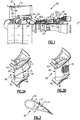
- Figures 2A and 2B illustrate one such component.
- the component is an airfoil 60, namely a vane.
- the vane can be a turbine vane, as represented at 60a in Figure 1 , or a compressor vane as represented at 60b in Figure 1 .
- the examples herein are described in the context of a vane, this disclosure is not limited to vanes or airfoils, and the examples may also be applicable to blade outer air seals or other components that are exposed to high temperatures in the core flow path.
- the airfoil 60 includes a body which generally includes inner and outer platforms 62/64 and an airfoil section 66 that extends radially between the inner and outer platforms 62/64.
- the airfoil section 66 may be hollow and can include one or more internal passages 68 ( Figure 3 ).
- a passage can include a cavity, a channel, or the like.
- the airfoil 60 includes a geometric segmented coating section 70, a portion of which is shown in cutaway in Figure 2B .
- the coating section 70 may be integral with the airfoil section 66, but could alternatively be a segment or panel that forms a portion of the airfoil section 66.
- the coating section 70 is located on a suction side (S) of the airfoil section 66.
- a coating section 70 could also be provided on the pressure side (P) of the airfoil section 66.
- the coating section 70 includes a segmented structure and a cooling scheme to enhance temperature resistance capability of the airfoil 60.
- Figure 3 illustrates a sectioned view through the airfoil section 66
- Figure 4 illustrates a sectioned view of the coating section 70.
- the coating section 70 includes a wall 72.
- the wall 72 includes a first side 72a that will most typically border the passage 68 and a second side 72b that is opposite the first side 72a.
- the second side 72b includes an array of cells 74 defined by cell sidewalls 74a.
- the array is a repeating geometric pattern of one or more cell geometries.
- the cell sidewalls 74a have a uniform thickness.
- the cells 74 are hexagonal (see Figure 6A ) but alternatively could be circular, ovular, other polygonal geometry, or mixed cell geometries.
- a coating 76 is disposed over the array of cells 74.
- the cells 74 mechanically facilitate bonding of the coating 76 on the wall 72.
- the coating 76 is a barrier coating, such as a thermal barrier or environmental barrier, which is formed of a ceramic material.
- a ceramic material is a compound of metallic or metalloid elements bonded with nonmetallic elements or metalloid elements primarily in ionic or covalent bonds.
- Example ceramic materials may include, but are not limited to, oxides, carbides, nitrides, borides, silicides, and combinations thereof.
- the coating 76 may be a monolayer coating but more typically will be a multi-layer coating. For instance, the coating 76 has a first coating layer 76a and a second coating layer 76b. In this example, the second coating layer 76b is a topcoat.
- the ceramic material of the coating 76 provides thermal and/or environmental resistance.
- the ceramic material may include or may be yttria stabilized with zirconia, hafnia, and/or gadolinia, gadolinia zirconate, molybdate, alumina, or combinations thereof.
- the ceramic material may include or may be a ceramic matrix composite which has a reinforcement phase, such as ceramic or carbon fibers, dispersed in a ceramic matrix formed of oxides, carbides, nitrides, borides, silicides, or combinations thereof.
- the coating 76 may also include a bond coat for attaching the ceramic material to the wall 72 and cells 74.
- the wall 72 and cells 74 may be formed of an alloy.
- Example alloys may include, but are not limited to, nickel alloys, cobalt alloys, a nickel alloy coated with cobalt or cobalt alloy, or a non-nickel alloys that do not substantially react with ceramic.
- the bond coat may include a nickel alloy, platinum, gold, silver, or MCrAlY, where the M includes at least one of nickel, cobalt, iron, or combinations thereof.
- the cell sidewalls 74a also facilitate reducing internal stresses in the coating 76 that may occur from sintering at relatively high surface temperatures during use in the engine 20.
- the sintering may result in partial melting, densification, and diffusional shrinkage of the coating 76 and thereby induce internal stresses.
- the cell sidewalls 74a serve to produce faults in at least the portion of the coating 76 above the cell sidewalls 74a.
- the faults provide locations for releasing energy associated with the internal stresses (e.g., reducing shear and radial stresses). That is, the energy associated with the internal stresses may be dissipated in the faults such that there is less energy available for causing delamination cracking between the coating 76 and the underlying wall 72.
- the wall 72 may be fabricated by investment casting, additive manufacturing, brazing, or combinations thereof, but is not limited to such techniques.
- the cells 74 can be separately fabricated and brazed to the remaining portion of the wall 72, which can be investment cast or additively fabricated.
- the cells 74 can be formed by other techniques, such as depositing an alloy coating and removing sections of the alloy coating by machining, electro-discharge machining (EDM), or other removal process.
- the coating 76 ceramic coating material is deposited over the cells 74.
- the deposition process can include, but is not limited to, plasma spray or physical vapor deposition.
- plasma spray is used to produce a more durable version of the coating 76.
- the coating 76 has a laminar microstructure with grains of ceramic material that have a high aspect ratio.
- the laminar microstructure is a product of the plasma spray process, in which droplets of melted or partially melted ceramic material are sprayed onto the cells 74. Upon impact, the droplets flatten and solidify, yielding the laminar microstructure. There may be voids or pores among the grains; however, the coating 76 is substantially fully dense.
- the coating 76 defines an exterior side 76c of the component 60, which in this example is the exterior side of the suction side of the airfoil section 66.
- One or more cooling passages 78 extend through the wall 72 and the coating 76.
- the cooling passage 78 fluidly connects the passage 68 and the exterior side 76c.
- the wall 72 defines a portion 78a of the cooling passage 78 and the coating 76 defines another portion 78b of the cooling passage 78.
- the portion 78a provides a majority of the cooling passage 78 in comparison to the portion 78b.
- the portion 78a provides approximately 50% to approximately 90% of the surface area of the cooling passage 78.
- the portion 78a is 60%, 70%, or 80% of the surface area.
- the airfoil section 66 has a row 80 of the cooling passages 78 that are generally aligned in a radial direction.
- Each such cooling passage 78 may slope relative to the coating 76.
- each such cooling passage 78 slopes along a central axis A1 ( Figure 4 ) that forms a non-perpendicular angle at the intersection of the axis A1 and the coating 76.
- Most typically, each cooling passage 78 will be sloped toward a trailing end of the airfoil section 66. The slope allows a film of cooling bleed air to be discharged along the exterior side 76c of the coating 76.
- the cooling bleed air also removes heat from the wall 72 and cell sidewalls 74a as it moves through the cooling passage 78.
- the cooling passage 78 generally has a rectangular, slot-like profile, which may be desired for providing film cooling.
- the rectangular profile has a first dimension D1, a second dimension D2, and an aspect ratio of D1/D2 that is greater than one.
- the cooling passage 78 may have a different, elongated profile geometry that has an aspect ratio of greater than one.
- the cooling passage 78 may also taper.
- the cooling passage 78 tapers (represented at "T") from the first side 72a toward the second side 72b but alternatively could be tapered from the second side 72b toward the first side 72a. The taper serves to accelerate or decelerate air flow.
- the taper may also serve as a self-healing type feature to provide more air flow as the coating section 70 erodes away and progressively opens larger cross-sections of the cooling passage 78.
- an inverse taper may provide less air flow by progressively opening smaller cross-sections of the cooling channel 78.
- the taper is not so great as to accelerate the cooling bleed air to a rate that it will be ejected and lost into the core gas path with flowing along the exterior surface 76c for film cooling.
- the cooling passage 78 may include a flow guide to control cooling bleed air flow through the cooling passage 78.
- Figure 5 illustrates a portion of an example cooling passage 178 with a flow guide 180.
- the flow guide 180 is tapered.
- the larger end of the flow guide is oriented toward the passage 68 and the narrower end is oriented toward the exterior side 76c.
- the tapered flow guide 180 orients or straightens cooling bleed air flow through the cooling passage 78.
- the tapered flow guide 180 may alternatively have other geometries, such as but not limited to circular, ovular, or polygonal.
- the cooling passages 78 may include flow guides of mixed geometries, wherein one or more cooling passages 78 includes one or more different flow guide geometries.
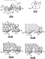
- Figures 6A, 6B, 6C, and 6D depict progressions through an example method of fabricating the component 60.
- the wall 72 initially has the array of cells 74 without the coating 76 yet deposited thereon.
- the encapsulation 82 projects beyond the array of cells 74.
- the encapsulation 82 projects above the top surfaces of the cell sidewalls 74a.
- the encapsulation 82 could be flush with the top surfaces of the cell sidewalls 74a or recessed below the top surfaces of the cell sidewalls 74a.
- the encapsulation 82 may be fabricated with, and thus integral with, the wall 72. In this regard, the wall 72 and encapsulation form a monolithic body.
- the first coating layer 76a is deposited on the wall 72 over the cells 74 and on the encapsulation 82.
- the first coating layer 76a completely covers the cells 74 and the encapsulation 82.
- a portion of the encapsulation 82 may be only thinly covered or may not include any, or any substantial amount, of the coating material.
- a portion of the first coating layer 76a is then removed along the array of cells 74, such as by machining, grinding, and/or abrading.
- the portion of the first coating layer 76a is selectively removed down to, or close to, the tops of the cell sidewalls 74a and the encapsulation 82 remains.
- the tops of the cell sidewalls 74a may be exposed in the process, which may be desirable for producing the faults discussed above.
- an abrasive is used for removal of the portion of the first coating layer 76a, it may be necessary to shield or mask the encapsulation 82 to avoid excessive alloy removal and damage of the wall 72.
- the encapsulation 82 is then removed, to open the cooling passage 78.
- the encapsulation 82 is removed by machining, grinding, electro-discharge machining (EDM), and/or abrasion such that the sides of the cooling passage 78 are flush or substantially flush with the tops of the cell sidewalls 74a. If the initial encapsulation 82 were instead flush with the tops of the cell sidewalls 74a or recessed, the encapsulation 82 is removed using similar techniques, but the sides of the cooling passage 78 are already flush or substantially flush with the tops of the cell sidewalls 74a.
- EDM electro-discharge machining
- the second coating layer 76b is deposited over the array of cells 74 and around the open cooling passage 78 (as shown in final form in Figure 4 ).
- the second coating layer 76b is relatively thin in thickness and there is therefore not a sufficient amount of coating material to bridge over the open cooling passage 78. Some of the coating material may deposit down into the cooling passage 78, but this would not be expected to plug the cooling passage 78 or substantially interfere with flow through the cooling passage 78. If desired, any such coating material that is deposited in the cooling passage 78 could be removed.
- the geometrically segmented coating section 70 has a relatively complex geometry, as well as the coating 76. Such a geometry in combination with the coating 76 presents challenges to integrating a cooling scheme, and doing so in a way that is manufacturable.
- the encapsulation 82 and process described herein provide a practical technique for forming the cooling passage 78 in the coating section 70 and also enable secondary features such as the flow guides 180 to be readily implemented.
Landscapes
- Engineering & Computer Science (AREA)
- Mechanical Engineering (AREA)
- General Engineering & Computer Science (AREA)
- Chemical & Material Sciences (AREA)
- Combustion & Propulsion (AREA)
- Materials Engineering (AREA)
- Physics & Mathematics (AREA)
- Thermal Sciences (AREA)
- Turbine Rotor Nozzle Sealing (AREA)
Applications Claiming Priority (1)
| Application Number | Priority Date | Filing Date | Title |
|---|---|---|---|
| US15/354,153 US10309238B2 (en) | 2016-11-17 | 2016-11-17 | Turbine engine component with geometrically segmented coating section and cooling passage |
Publications (2)
| Publication Number | Publication Date |
|---|---|
| EP3323996A1 true EP3323996A1 (fr) | 2018-05-23 |
| EP3323996B1 EP3323996B1 (fr) | 2022-04-20 |
Family
ID=60387907
Family Applications (1)
| Application Number | Title | Priority Date | Filing Date |
|---|---|---|---|
| EP17202298.0A Active EP3323996B1 (fr) | 2016-11-17 | 2017-11-17 | Composant de moteur à turbine avec section de revêtement segmenté géométriquement et passage de refroidissement |
Country Status (2)
| Country | Link |
|---|---|
| US (1) | US10309238B2 (fr) |
| EP (1) | EP3323996B1 (fr) |
Families Citing this family (2)
| Publication number | Priority date | Publication date | Assignee | Title |
|---|---|---|---|---|
| US10662779B2 (en) * | 2016-11-17 | 2020-05-26 | Raytheon Technologies Corporation | Gas turbine engine component with degradation cooling scheme |
| US10370976B2 (en) * | 2017-08-17 | 2019-08-06 | United Technologies Corporation | Directional cooling arrangement for airfoils |
Citations (6)
| Publication number | Priority date | Publication date | Assignee | Title |
|---|---|---|---|---|
| EP1496140A1 (fr) * | 2003-07-09 | 2005-01-12 | Siemens Aktiengesellschaft | Structure stratifiée et procédé pour sa production |
| EP2131108A2 (fr) * | 2008-06-06 | 2009-12-09 | United Technologies Corporation | Conception d'un trou de refroidissement à film à vortex inversé |
| US20100074726A1 (en) * | 2008-09-19 | 2010-03-25 | Merrill Gary B | Gas turbine airfoil |
| US20130209229A1 (en) * | 2012-02-15 | 2013-08-15 | United Technologies Corporation | Gas turbine engine component with converging/diverging cooling passage |
| EP2641993A2 (fr) * | 2012-03-22 | 2013-09-25 | Rolls-Royce plc | Procédé de fabrication d'un article revêtu d'une barrière thermique |
| EP2815823A1 (fr) * | 2013-06-18 | 2014-12-24 | Alstom Technology Ltd | Procédé de production d'un article en trois dimensions et article produit avec un tel procédé |
Family Cites Families (53)
| Publication number | Priority date | Publication date | Assignee | Title |
|---|---|---|---|---|
| US3215511A (en) | 1962-03-30 | 1965-11-02 | Union Carbide Corp | Gas turbine nozzle vane and like articles |
| US4137008A (en) | 1977-09-21 | 1979-01-30 | The United States Of America As Represented By The Secretary Of The Navy | Adjustable blowing slot for circulation control airfoil |
| US4247259A (en) | 1979-04-18 | 1981-01-27 | Avco Corporation | Composite ceramic/metallic turbine blade and method of making same |
| DE3110098C2 (de) | 1981-03-16 | 1983-03-17 | MTU Motoren- und Turbinen-Union München GmbH, 8000 München | Turbinenleitschaufel für Gasturbinentriebwerke |
| JPS6166802A (ja) | 1984-09-10 | 1986-04-05 | Mitsubishi Heavy Ind Ltd | ガスタ−ビンのタ−ビン翼 |
| US4914794A (en) | 1986-08-07 | 1990-04-10 | Allied-Signal Inc. | Method of making an abradable strain-tolerant ceramic coated turbine shroud |
| US4867639A (en) * | 1987-09-22 | 1989-09-19 | Allied-Signal Inc. | Abradable shroud coating |
| US5030060A (en) * | 1988-10-20 | 1991-07-09 | The United States Of America As Represented By The Secretary Of The Air Force | Method and apparatus for cooling high temperature ceramic turbine blade portions |
| JPH05321602A (ja) | 1992-05-25 | 1993-12-07 | Toshiba Corp | ガスタービン動翼 |
| DE4238369C2 (de) | 1992-11-13 | 1996-09-26 | Mtu Muenchen Gmbh | Bauteil aus einem metallischen Grundsubstrat mit keramischer Beschichtung |
| US5419971A (en) | 1993-03-03 | 1995-05-30 | General Electric Company | Enhanced thermal barrier coating system |
| US5358379A (en) | 1993-10-27 | 1994-10-25 | Westinghouse Electric Corporation | Gas turbine vane |
| US5538380A (en) | 1994-06-27 | 1996-07-23 | Solar Turbines Incorporated | Metallic nut for use with ceramic threads |
| US5558922A (en) | 1994-12-28 | 1996-09-24 | General Electric Company | Thick thermal barrier coating having grooves for enhanced strain tolerance |
| US5634771A (en) | 1995-09-25 | 1997-06-03 | General Electric Company | Partially-metallic blade for a gas turbine |
| US6102656A (en) | 1995-09-26 | 2000-08-15 | United Technologies Corporation | Segmented abradable ceramic coating |
| US5771577A (en) * | 1996-05-17 | 1998-06-30 | General Electric Company | Method for making a fluid cooled article with protective coating |
| US5951892A (en) | 1996-12-10 | 1999-09-14 | Chromalloy Gas Turbine Corporation | Method of making an abradable seal by laser cutting |
| US6224963B1 (en) | 1997-05-14 | 2001-05-01 | Alliedsignal Inc. | Laser segmented thick thermal barrier coatings for turbine shrouds |
| US6000906A (en) | 1997-09-12 | 1999-12-14 | Alliedsignal Inc. | Ceramic airfoil |
| US6243948B1 (en) * | 1999-11-18 | 2001-06-12 | General Electric Company | Modification and repair of film cooling holes in gas turbine engine components |
| US6316078B1 (en) | 2000-03-14 | 2001-11-13 | The United States Of America As Represented By The Administrator Of The National Aeronautics And Space Administration | Segmented thermal barrier coating |
| US6514046B1 (en) | 2000-09-29 | 2003-02-04 | Siemens Westinghouse Power Corporation | Ceramic composite vane with metallic substructure |
| US6846574B2 (en) | 2001-05-16 | 2005-01-25 | Siemens Westinghouse Power Corporation | Honeycomb structure thermal barrier coating |
| US6543996B2 (en) | 2001-06-28 | 2003-04-08 | General Electric Company | Hybrid turbine nozzle |
| US6703137B2 (en) | 2001-08-02 | 2004-03-09 | Siemens Westinghouse Power Corporation | Segmented thermal barrier coating and method of manufacturing the same |
| US6709230B2 (en) | 2002-05-31 | 2004-03-23 | Siemens Westinghouse Power Corporation | Ceramic matrix composite gas turbine vane |
| US7080971B2 (en) | 2003-03-12 | 2006-07-25 | Florida Turbine Technologies, Inc. | Cooled turbine spar shell blade construction |
| US7104756B2 (en) | 2004-08-11 | 2006-09-12 | United Technologies Corporation | Temperature tolerant vane assembly |
| US7435058B2 (en) | 2005-01-18 | 2008-10-14 | Siemens Power Generation, Inc. | Ceramic matrix composite vane with chordwise stiffener |
| US7326030B2 (en) | 2005-02-02 | 2008-02-05 | Siemens Power Generation, Inc. | Support system for a composite airfoil in a turbine engine |
| US7316539B2 (en) | 2005-04-07 | 2008-01-08 | Siemens Power Generation, Inc. | Vane assembly with metal trailing edge segment |
| US7452182B2 (en) | 2005-04-07 | 2008-11-18 | Siemens Energy, Inc. | Multi-piece turbine vane assembly |
| US7329087B2 (en) | 2005-09-19 | 2008-02-12 | General Electric Company | Seal-less CMC vane to platform interfaces |
| US7686570B2 (en) * | 2006-08-01 | 2010-03-30 | Siemens Energy, Inc. | Abradable coating system |
| US7520725B1 (en) | 2006-08-11 | 2009-04-21 | Florida Turbine Technologies, Inc. | Turbine airfoil with near-wall leading edge multi-holes cooling |
| US9039358B2 (en) | 2007-01-03 | 2015-05-26 | United Technologies Corporation | Replaceable blade outer air seal design |
| US20100136258A1 (en) | 2007-04-25 | 2010-06-03 | Strock Christopher W | Method for improved ceramic coating |
| US7901181B1 (en) * | 2007-05-02 | 2011-03-08 | Florida Turbine Technologies, Inc. | Turbine blade with triple spiral serpentine flow cooling circuits |
| US7963745B1 (en) | 2007-07-10 | 2011-06-21 | Florida Turbine Technologies, Inc. | Composite turbine blade |
| US8182208B2 (en) | 2007-07-10 | 2012-05-22 | United Technologies Corp. | Gas turbine systems involving feather seals |
| US8202043B2 (en) | 2007-10-15 | 2012-06-19 | United Technologies Corp. | Gas turbine engines and related systems involving variable vanes |
| US8079806B2 (en) | 2007-11-28 | 2011-12-20 | United Technologies Corporation | Segmented ceramic layer for member of gas turbine engine |
| GB2458685B (en) | 2008-03-28 | 2010-05-12 | Rolls Royce Plc | An article formed from a composite material |
| US8251651B2 (en) | 2009-01-28 | 2012-08-28 | United Technologies Corporation | Segmented ceramic matrix composite turbine airfoil component |
| US8109724B2 (en) | 2009-03-26 | 2012-02-07 | United Technologies Corporation | Recessed metering standoffs for airfoil baffle |
| US8585368B2 (en) | 2009-04-16 | 2013-11-19 | United Technologies Corporation | Hybrid structure airfoil |
| US8366392B1 (en) | 2009-05-06 | 2013-02-05 | Florida Turbine Technologies, Inc. | Composite air cooled turbine rotor blade |
| US8852720B2 (en) * | 2009-07-17 | 2014-10-07 | Rolls-Royce Corporation | Substrate features for mitigating stress |
| US8197211B1 (en) | 2009-09-25 | 2012-06-12 | Florida Turbine Technologies, Inc. | Composite air cooled turbine rotor blade |
| US8506243B2 (en) | 2009-11-19 | 2013-08-13 | United Technologies Corporation | Segmented thermally insulating coating |
| DE102013219774A1 (de) | 2013-09-30 | 2015-04-02 | MTU Aero Engines AG | Schaufel für eine Gasturbine |
| US10107117B2 (en) | 2014-09-30 | 2018-10-23 | United Technologies Corporation | Airfoil assembly with spacer and tie-spar |
-
2016
- 2016-11-17 US US15/354,153 patent/US10309238B2/en active Active
-
2017
- 2017-11-17 EP EP17202298.0A patent/EP3323996B1/fr active Active
Patent Citations (6)
| Publication number | Priority date | Publication date | Assignee | Title |
|---|---|---|---|---|
| EP1496140A1 (fr) * | 2003-07-09 | 2005-01-12 | Siemens Aktiengesellschaft | Structure stratifiée et procédé pour sa production |
| EP2131108A2 (fr) * | 2008-06-06 | 2009-12-09 | United Technologies Corporation | Conception d'un trou de refroidissement à film à vortex inversé |
| US20100074726A1 (en) * | 2008-09-19 | 2010-03-25 | Merrill Gary B | Gas turbine airfoil |
| US20130209229A1 (en) * | 2012-02-15 | 2013-08-15 | United Technologies Corporation | Gas turbine engine component with converging/diverging cooling passage |
| EP2641993A2 (fr) * | 2012-03-22 | 2013-09-25 | Rolls-Royce plc | Procédé de fabrication d'un article revêtu d'une barrière thermique |
| EP2815823A1 (fr) * | 2013-06-18 | 2014-12-24 | Alstom Technology Ltd | Procédé de production d'un article en trois dimensions et article produit avec un tel procédé |
Also Published As
| Publication number | Publication date |
|---|---|
| US20180135443A1 (en) | 2018-05-17 |
| US10309238B2 (en) | 2019-06-04 |
| EP3323996B1 (fr) | 2022-04-20 |
Similar Documents
| Publication | Publication Date | Title |
|---|---|---|
| EP3323984B1 (fr) | Profil aérodynamique comportant une section de revêtement segmentée géométriquement | |
| EP3351729B1 (fr) | Composant de moteur à turbine à gaz et moteur à turbine à gaz associé | |
| EP3339571B1 (fr) | Profil aérodynamique comportant un panneau ayant un guide d'écoulement | |
| US11149573B2 (en) | Airfoil with seal between end wall and airfoil section | |
| EP3336314B1 (fr) | Profil aérodynamique comportant une section de revêtement segmentée géométriquement et présentant une caractéristique de liaison secondaire mécanique | |
| US11319817B2 (en) | Airfoil with panel and side edge cooling | |
| EP3323990A1 (fr) | Profil aérodynamique, moteur à turbine à gaz associé et procédé d'assemblage d'un profil aérodynamique | |
| EP3323986B1 (fr) | Profil aérodynamique comportant une section de revêtement segmentée géométriquement | |
| US10309226B2 (en) | Airfoil having panels | |
| EP3323983B1 (fr) | Aube fixe et moteur à turbine à gaz ayant une telle aube | |
| EP3323996B1 (fr) | Composant de moteur à turbine avec section de revêtement segmenté géométriquement et passage de refroidissement | |
| EP3556998B1 (fr) | Joint d'air ayant une partie de trajectoire de gaz comportant un revêtement segmenté géométriquement |
Legal Events
| Date | Code | Title | Description |
|---|---|---|---|
| PUAI | Public reference made under article 153(3) epc to a published international application that has entered the european phase |
Free format text: ORIGINAL CODE: 0009012 |
|
| STAA | Information on the status of an ep patent application or granted ep patent |
Free format text: STATUS: THE APPLICATION HAS BEEN PUBLISHED |
|
| AK | Designated contracting states |
Kind code of ref document: A1 Designated state(s): AL AT BE BG CH CY CZ DE DK EE ES FI FR GB GR HR HU IE IS IT LI LT LU LV MC MK MT NL NO PL PT RO RS SE SI SK SM TR |
|
| AX | Request for extension of the european patent |
Extension state: BA ME |
|
| STAA | Information on the status of an ep patent application or granted ep patent |
Free format text: STATUS: REQUEST FOR EXAMINATION WAS MADE |
|
| 17P | Request for examination filed |
Effective date: 20181123 |
|
| RBV | Designated contracting states (corrected) |
Designated state(s): AL AT BE BG CH CY CZ DE DK EE ES FI FR GB GR HR HU IE IS IT LI LT LU LV MC MK MT NL NO PL PT RO RS SE SI SK SM TR |
|
| STAA | Information on the status of an ep patent application or granted ep patent |
Free format text: STATUS: REQUEST FOR EXAMINATION WAS MADE |
|
| RAP1 | Party data changed (applicant data changed or rights of an application transferred) |
Owner name: RAYTHEON TECHNOLOGIES CORPORATION |
|
| GRAP | Despatch of communication of intention to grant a patent |
Free format text: ORIGINAL CODE: EPIDOSNIGR1 |
|
| STAA | Information on the status of an ep patent application or granted ep patent |
Free format text: STATUS: GRANT OF PATENT IS INTENDED |
|
| INTG | Intention to grant announced |
Effective date: 20211216 |
|
| GRAS | Grant fee paid |
Free format text: ORIGINAL CODE: EPIDOSNIGR3 |
|
| GRAA | (expected) grant |
Free format text: ORIGINAL CODE: 0009210 |
|
| STAA | Information on the status of an ep patent application or granted ep patent |
Free format text: STATUS: THE PATENT HAS BEEN GRANTED |
|
| AK | Designated contracting states |
Kind code of ref document: B1 Designated state(s): AL AT BE BG CH CY CZ DE DK EE ES FI FR GB GR HR HU IE IS IT LI LT LU LV MC MK MT NL NO PL PT RO RS SE SI SK SM TR |
|
| REG | Reference to a national code |
Ref country code: GB Ref legal event code: FG4D |
|
| REG | Reference to a national code |
Ref country code: CH Ref legal event code: EP |
|
| REG | Reference to a national code |
Ref country code: IE Ref legal event code: FG4D |
|
| REG | Reference to a national code |
Ref country code: DE Ref legal event code: R096 Ref document number: 602017056188 Country of ref document: DE |
|
| REG | Reference to a national code |
Ref country code: AT Ref legal event code: REF Ref document number: 1485297 Country of ref document: AT Kind code of ref document: T Effective date: 20220515 |
|
| REG | Reference to a national code |
Ref country code: LT Ref legal event code: MG9D |
|
| REG | Reference to a national code |
Ref country code: NL Ref legal event code: MP Effective date: 20220420 |
|
| REG | Reference to a national code |
Ref country code: AT Ref legal event code: MK05 Ref document number: 1485297 Country of ref document: AT Kind code of ref document: T Effective date: 20220420 |
|
| PG25 | Lapsed in a contracting state [announced via postgrant information from national office to epo] |
Ref country code: NL Free format text: LAPSE BECAUSE OF FAILURE TO SUBMIT A TRANSLATION OF THE DESCRIPTION OR TO PAY THE FEE WITHIN THE PRESCRIBED TIME-LIMIT Effective date: 20220420 |
|
| PG25 | Lapsed in a contracting state [announced via postgrant information from national office to epo] |
Ref country code: SE Free format text: LAPSE BECAUSE OF FAILURE TO SUBMIT A TRANSLATION OF THE DESCRIPTION OR TO PAY THE FEE WITHIN THE PRESCRIBED TIME-LIMIT Effective date: 20220420 Ref country code: PT Free format text: LAPSE BECAUSE OF FAILURE TO SUBMIT A TRANSLATION OF THE DESCRIPTION OR TO PAY THE FEE WITHIN THE PRESCRIBED TIME-LIMIT Effective date: 20220822 Ref country code: NO Free format text: LAPSE BECAUSE OF FAILURE TO SUBMIT A TRANSLATION OF THE DESCRIPTION OR TO PAY THE FEE WITHIN THE PRESCRIBED TIME-LIMIT Effective date: 20220720 Ref country code: LT Free format text: LAPSE BECAUSE OF FAILURE TO SUBMIT A TRANSLATION OF THE DESCRIPTION OR TO PAY THE FEE WITHIN THE PRESCRIBED TIME-LIMIT Effective date: 20220420 Ref country code: HR Free format text: LAPSE BECAUSE OF FAILURE TO SUBMIT A TRANSLATION OF THE DESCRIPTION OR TO PAY THE FEE WITHIN THE PRESCRIBED TIME-LIMIT Effective date: 20220420 Ref country code: GR Free format text: LAPSE BECAUSE OF FAILURE TO SUBMIT A TRANSLATION OF THE DESCRIPTION OR TO PAY THE FEE WITHIN THE PRESCRIBED TIME-LIMIT Effective date: 20220721 Ref country code: FI Free format text: LAPSE BECAUSE OF FAILURE TO SUBMIT A TRANSLATION OF THE DESCRIPTION OR TO PAY THE FEE WITHIN THE PRESCRIBED TIME-LIMIT Effective date: 20220420 Ref country code: ES Free format text: LAPSE BECAUSE OF FAILURE TO SUBMIT A TRANSLATION OF THE DESCRIPTION OR TO PAY THE FEE WITHIN THE PRESCRIBED TIME-LIMIT Effective date: 20220420 Ref country code: BG Free format text: LAPSE BECAUSE OF FAILURE TO SUBMIT A TRANSLATION OF THE DESCRIPTION OR TO PAY THE FEE WITHIN THE PRESCRIBED TIME-LIMIT Effective date: 20220720 Ref country code: AT Free format text: LAPSE BECAUSE OF FAILURE TO SUBMIT A TRANSLATION OF THE DESCRIPTION OR TO PAY THE FEE WITHIN THE PRESCRIBED TIME-LIMIT Effective date: 20220420 |
|
| PG25 | Lapsed in a contracting state [announced via postgrant information from national office to epo] |
Ref country code: RS Free format text: LAPSE BECAUSE OF FAILURE TO SUBMIT A TRANSLATION OF THE DESCRIPTION OR TO PAY THE FEE WITHIN THE PRESCRIBED TIME-LIMIT Effective date: 20220420 Ref country code: PL Free format text: LAPSE BECAUSE OF FAILURE TO SUBMIT A TRANSLATION OF THE DESCRIPTION OR TO PAY THE FEE WITHIN THE PRESCRIBED TIME-LIMIT Effective date: 20220420 Ref country code: LV Free format text: LAPSE BECAUSE OF FAILURE TO SUBMIT A TRANSLATION OF THE DESCRIPTION OR TO PAY THE FEE WITHIN THE PRESCRIBED TIME-LIMIT Effective date: 20220420 Ref country code: IS Free format text: LAPSE BECAUSE OF FAILURE TO SUBMIT A TRANSLATION OF THE DESCRIPTION OR TO PAY THE FEE WITHIN THE PRESCRIBED TIME-LIMIT Effective date: 20220820 |
|
| REG | Reference to a national code |
Ref country code: DE Ref legal event code: R097 Ref document number: 602017056188 Country of ref document: DE |
|
| PG25 | Lapsed in a contracting state [announced via postgrant information from national office to epo] |
Ref country code: SM Free format text: LAPSE BECAUSE OF FAILURE TO SUBMIT A TRANSLATION OF THE DESCRIPTION OR TO PAY THE FEE WITHIN THE PRESCRIBED TIME-LIMIT Effective date: 20220420 Ref country code: SK Free format text: LAPSE BECAUSE OF FAILURE TO SUBMIT A TRANSLATION OF THE DESCRIPTION OR TO PAY THE FEE WITHIN THE PRESCRIBED TIME-LIMIT Effective date: 20220420 Ref country code: RO Free format text: LAPSE BECAUSE OF FAILURE TO SUBMIT A TRANSLATION OF THE DESCRIPTION OR TO PAY THE FEE WITHIN THE PRESCRIBED TIME-LIMIT Effective date: 20220420 Ref country code: EE Free format text: LAPSE BECAUSE OF FAILURE TO SUBMIT A TRANSLATION OF THE DESCRIPTION OR TO PAY THE FEE WITHIN THE PRESCRIBED TIME-LIMIT Effective date: 20220420 Ref country code: DK Free format text: LAPSE BECAUSE OF FAILURE TO SUBMIT A TRANSLATION OF THE DESCRIPTION OR TO PAY THE FEE WITHIN THE PRESCRIBED TIME-LIMIT Effective date: 20220420 Ref country code: CZ Free format text: LAPSE BECAUSE OF FAILURE TO SUBMIT A TRANSLATION OF THE DESCRIPTION OR TO PAY THE FEE WITHIN THE PRESCRIBED TIME-LIMIT Effective date: 20220420 |
|
| PLBE | No opposition filed within time limit |
Free format text: ORIGINAL CODE: 0009261 |
|
| STAA | Information on the status of an ep patent application or granted ep patent |
Free format text: STATUS: NO OPPOSITION FILED WITHIN TIME LIMIT |
|
| 26N | No opposition filed |
Effective date: 20230123 |
|
| PG25 | Lapsed in a contracting state [announced via postgrant information from national office to epo] |
Ref country code: AL Free format text: LAPSE BECAUSE OF FAILURE TO SUBMIT A TRANSLATION OF THE DESCRIPTION OR TO PAY THE FEE WITHIN THE PRESCRIBED TIME-LIMIT Effective date: 20220420 |
|
| PG25 | Lapsed in a contracting state [announced via postgrant information from national office to epo] |
Ref country code: SI Free format text: LAPSE BECAUSE OF FAILURE TO SUBMIT A TRANSLATION OF THE DESCRIPTION OR TO PAY THE FEE WITHIN THE PRESCRIBED TIME-LIMIT Effective date: 20220420 |
|
| P01 | Opt-out of the competence of the unified patent court (upc) registered |
Effective date: 20230520 |
|
| PG25 | Lapsed in a contracting state [announced via postgrant information from national office to epo] |
Ref country code: MC Free format text: LAPSE BECAUSE OF FAILURE TO SUBMIT A TRANSLATION OF THE DESCRIPTION OR TO PAY THE FEE WITHIN THE PRESCRIBED TIME-LIMIT Effective date: 20220420 |
|
| REG | Reference to a national code |
Ref country code: CH Ref legal event code: PL |
|
| REG | Reference to a national code |
Ref country code: BE Ref legal event code: MM Effective date: 20221130 |
|
| PG25 | Lapsed in a contracting state [announced via postgrant information from national office to epo] |
Ref country code: LI Free format text: LAPSE BECAUSE OF NON-PAYMENT OF DUE FEES Effective date: 20221130 Ref country code: CH Free format text: LAPSE BECAUSE OF NON-PAYMENT OF DUE FEES Effective date: 20221130 |
|
| PG25 | Lapsed in a contracting state [announced via postgrant information from national office to epo] |
Ref country code: LU Free format text: LAPSE BECAUSE OF NON-PAYMENT OF DUE FEES Effective date: 20221117 |
|
| PG25 | Lapsed in a contracting state [announced via postgrant information from national office to epo] |
Ref country code: IE Free format text: LAPSE BECAUSE OF NON-PAYMENT OF DUE FEES Effective date: 20221117 |
|
| PG25 | Lapsed in a contracting state [announced via postgrant information from national office to epo] |
Ref country code: BE Free format text: LAPSE BECAUSE OF NON-PAYMENT OF DUE FEES Effective date: 20221130 |
|
| PGFP | Annual fee paid to national office [announced via postgrant information from national office to epo] |
Ref country code: GB Payment date: 20231019 Year of fee payment: 7 |
|
| PG25 | Lapsed in a contracting state [announced via postgrant information from national office to epo] |
Ref country code: IT Free format text: LAPSE BECAUSE OF FAILURE TO SUBMIT A TRANSLATION OF THE DESCRIPTION OR TO PAY THE FEE WITHIN THE PRESCRIBED TIME-LIMIT Effective date: 20220420 |
|
| PGFP | Annual fee paid to national office [announced via postgrant information from national office to epo] |
Ref country code: FR Payment date: 20231019 Year of fee payment: 7 Ref country code: DE Payment date: 20231019 Year of fee payment: 7 |
|
| PG25 | Lapsed in a contracting state [announced via postgrant information from national office to epo] |
Ref country code: HU Free format text: LAPSE BECAUSE OF FAILURE TO SUBMIT A TRANSLATION OF THE DESCRIPTION OR TO PAY THE FEE WITHIN THE PRESCRIBED TIME-LIMIT; INVALID AB INITIO Effective date: 20171117 |
|
| PG25 | Lapsed in a contracting state [announced via postgrant information from national office to epo] |
Ref country code: CY Free format text: LAPSE BECAUSE OF FAILURE TO SUBMIT A TRANSLATION OF THE DESCRIPTION OR TO PAY THE FEE WITHIN THE PRESCRIBED TIME-LIMIT Effective date: 20220420 |