EP3323755A1 - Electronic seal and electronic sealing system - Google Patents
Electronic seal and electronic sealing system Download PDFInfo
- Publication number
- EP3323755A1 EP3323755A1 EP16823773.3A EP16823773A EP3323755A1 EP 3323755 A1 EP3323755 A1 EP 3323755A1 EP 16823773 A EP16823773 A EP 16823773A EP 3323755 A1 EP3323755 A1 EP 3323755A1
- Authority
- EP
- European Patent Office
- Prior art keywords
- electronic seal
- box
- magnet
- electronic
- seal
- Prior art date
- Legal status (The legal status is an assumption and is not a legal conclusion. Google has not performed a legal analysis and makes no representation as to the accuracy of the status listed.)
- Granted
Links
Images


Classifications
-
- B—PERFORMING OPERATIONS; TRANSPORTING
- B65—CONVEYING; PACKING; STORING; HANDLING THIN OR FILAMENTARY MATERIAL
- B65D—CONTAINERS FOR STORAGE OR TRANSPORT OF ARTICLES OR MATERIALS, e.g. BAGS, BARRELS, BOTTLES, BOXES, CANS, CARTONS, CRATES, DRUMS, JARS, TANKS, HOPPERS, FORWARDING CONTAINERS; ACCESSORIES, CLOSURES, OR FITTINGS THEREFOR; PACKAGING ELEMENTS; PACKAGES
- B65D90/00—Component parts, details or accessories for large containers
- B65D90/48—Arrangements of indicating or measuring devices
-
- G—PHYSICS
- G09—EDUCATION; CRYPTOGRAPHY; DISPLAY; ADVERTISING; SEALS
- G09F—DISPLAYING; ADVERTISING; SIGNS; LABELS OR NAME-PLATES; SEALS
- G09F3/00—Labels, tag tickets, or similar identification or indication means; Seals; Postage or like stamps
- G09F3/02—Forms or constructions
- G09F3/03—Forms or constructions of security seals
-
- G—PHYSICS
- G09—EDUCATION; CRYPTOGRAPHY; DISPLAY; ADVERTISING; SEALS
- G09F—DISPLAYING; ADVERTISING; SIGNS; LABELS OR NAME-PLATES; SEALS
- G09F3/00—Labels, tag tickets, or similar identification or indication means; Seals; Postage or like stamps
- G09F3/02—Forms or constructions
- G09F3/03—Forms or constructions of security seals
- G09F3/0305—Forms or constructions of security seals characterised by the type of seal used
- G09F3/0329—Forms or constructions of security seals characterised by the type of seal used having electronic sealing means
Definitions
- the present invention relates to an electronic seal and an electronic seal system.
- An existing container employs a lead seal, which requires manual working and results in waste of lead.
- the lead seal is likely to be remade by forging after being illegally sheared off.
- the existing container also employs a sensor-type seal for sealing, for example, a clamping sensor seal between door leaves of the container.
- a clamping sensor seal is installed between door leaves. When the door is opened, the clamping sensor seal sends information to a control center to report, so as to prevent illegally opening the door.
- a clamping sensor seal needs to be installed by opening the door, such a clamping sensor seal can not be used if it requires to perform protection detection in a case of closing the door.
- an object of the present invention is to provide an electronic seal, which can be reused and installed for use without opening the door of a container, so as to solve part or all of problems of the seal in the prior art.
- Another object of the present invention is to provide an electronic seal convenient to install and disassemble.
- a further object of the present invention is to provide an electronic seal which can be protected from damage and forging.
- an electronic seal for indicating whether an attached box is opened, wherein the electronic seal comprises a housing having a first surface and a second surface, the electronic seal further comprises at least one magnet and at least one Hall element paired with the magnet, and the magnet and the Hall element are arranged in the housing, wherein the first surface is adapted to contact and fit with the box, and after said magnet is attached on the box, the magnet and the Hall element cooperate to send a signal that said electronic seal is moved, when said electronic seal leaves the box.
- an electronic seal system comprising a customs lock and at least one electronic seal described above, wherein each electronic seal establishes data communication with said customs lock configured to send information of the electronic seal to users.
- an electronic seal 11 is provided, for indicating whether a sealed box 2 is opened.
- Figs. 1A and 1B show an L-shaped electronic seal 11 of the present invention.
- the electronic seal 11 comprises an integrally formed housing 114, which can be formed by an ultrasonic injection molding process, for example.
- the integrated housing 114 has the advantage that entering the inside of the housing 114 will inevitably cause a damaged trace on the housing 114. In other words, if access to the inside of the housing 114 is desired, the housing 114 must be opened or damaged, and a trace will be left on the surface of the housing 114 in opening or damaging the housing 114, so inspectors could know the electronic seal has been damaged.
- the integrated housing 114 can be prevented from being illegally damaged.
- the integrated housing 114 comprises a front face 115 (corresponding to the second surface) and a back face 116 (corresponding to the first surface).
- the front face 115 of the housing 114 faces outwards, and the back face 116 of the housing 114 is adapted to contact and fit with the sealed box 2 (corresponding to the attached box).
- "Fit” refers to that the back face 116 of the housing 114 is substantially complementary with the surface of the box 2 to be contacted, so that after the back face 116 of the housing 114 and the surface of the box 2 contact and fit with each other, no obvious gap is formed between the back face 116 of the housing 114 and the surface of the box 2.
- Tools such as a blade, a screw driver, etc. or foreign objects cannot enter the back face 116 of the housing 114, so as to prevent the back face 116 of the housing 114 from being damaged.
- the electronic seal 11 further comprises at least one magnet 111 and at least one Hall element 112 paired with the magnet.
- the magnet and the Hall element are arranged in the housing 114.
- the Hall element is adapted to send a warning signal when the housing 114 of the electronic seal 11 is opened.
- a very strong magnetic attractive force is generated when the magnet 111 contacts and fits with the metal box 2 such as a steel container, accordingly, the electronic seal 11 is attached and fixed on the surface of the box 2 of the container.
- the electronic seal 11 is fixed on the surface of the box 2, no part of the back face 116 of the housing 114 of the electronic seal 11 can be contacted.
- the back face 116 of the electronic seal 11 can be contacted only when the electronic seal 11 is pried off the box 2, but in such case, the electronic seal 11 will send a signal indicating the electronic seal 11 has left the box 2.
- the electronic seal 11 comprises at least one magnet 111 and at least one Hall element 112 paired with the magnet.
- the state of the Hall element 112 is "0"; and when the magnet 111 is attached on the metal box 2, the magnet 111 and the Hall element 112 interact with each other, so that the state of the Hall element 112 is "I”.
- the state of the Hall element 112 is recorded; and when the state of the Hall element 112 changes, the Hall element 112 will send out state information through an antenna. In such a way, an operator can obtain change of the state of the electronic seal 11 and information that the electronic seal 11 is moved.
- the magnet of the electronic seal is not only adapted to attach the electronic seal to the metal box through magnetic attractive force, but also reflect the state of the electronic seal through interaction with the Hall element.
- a door 20 may be removed by cutting an L-shaped hinge 1, which is welded on the box 2 and connects the door 20 and a side edge 21, for example, of the box 2 (a part of the hinge 1 is welded on the door 20, the other part is welded on a side of the box 2 orthogonal to the door 20), and after illegal movement is completed, the hinge 1 is welded on the box 2 again, so as to avoid that the door 20 is found be opened.
- the electronic seal 11 may cover the hinge 1 and protect the hinge 1 from contact or removal, thereby preventing criminal behaviors.
- Such an electronic seal 11 may be in the shape of L as shown in Figs.
- the electronic seal 11 covers the hinge 1 in two directions of the L-shaped hinge perpendicular to each other to be attached to the box 2, thereby protecting the hinge 1. Any action damaging the hinge must be performed by removing the electronic seal 11, and illegally removing the electronic seal 11 will trigger warning.
- the electronic seal 11 may further comprise one or more additional Hall elements 117. The additional Hall elements send a signal indicating the housing 114 is damaged when the housing 114 of the electronic seal 11 is damaged. Due to the additional Hall elements 117, the integrally formed housing 114 cannot be damaged, and the electronic seal 11 itself is monitored.
- the additional Hall elements 117 are distributed in the electronic seal, and mutually cooperate with magnet matched with the same and arranged in the electronic seal, and when the housing 114 of the electronic seal is damaged, the additional Hall elements 117 send a signal.
- the additional Hall elements 117 mutually cooperate with the magnet 111, which is arranged in the electronic seal and adapted to determine whether the electronic seal leaves the box.
- the magnet 111 can cooperate with the additional Hall elements 117 and at the same time protect the housing of the electronic seal through cooperation with the additional Hall elements 117.
- the electronic seal 11 may further comprise one or more additional optical elements.
- the additional optical elements are arranged at one or more positions in the electronic seal, and these additional optical elements may comprise, for example, a optical sensor.
- a optical sensor When the electronic seal is damaged and external light irradiates to the inside of the electronic seal, light is sensed by an optical sensor, and then a signal is sent for warning.
- the optical sensor may comprise an infrared sensor, an ultraviolet sensor, a broadband optical sensor or the like, for example.
- the optical sensor may be an active optical sensor.
- the electronic seal 11 may further comprise one or more additional optical elements and one or more additional Hall elements 117.
- Such a structure is favorable and can provide redundant protection.
- the electronic seal 11 comprises two magnets 111 and two Hall elements 112 respectively paired with the two magnets.
- Two magnets 111 and two Hall elements 112 are respectively disposed at positions adjacent to two end portions of the electronic seal 11, for example, as shown in Fig. 1B .
- One of the functions of the magnets 111 is fixing the electronic seal 11.
- the two magnets 111 respectively are arranged adjacent to two ends of the electronic seal 11 may maintain the electronic seal 11 to be fixed on the box 2 in a balancing manner.
- the magnets 111 are also adapted to form the warning together with the Hall elements 112.
- the state of the Hall element 112 is 1; and when the magnet 111 leaves the box 2, the state of the Hall element 112 is changed to be 0, and is sent out. Accordingly, the state of the electronic seal 11 may be determined.
- the electronic seal 11 further comprises a magnet locking device 113.
- the extending and retracting of the magnet 111 is controlled by virtue of the magnet locking device 113.
- the magnet locking device 113 is adapted to drive the magnet 111 to contact or leave the box 2.
- the magnet locking device 113 comprises a lock plunger adapted to be operated on the front face 115 (corresponding to the second surface), and a user drives said magnet 111 to contact or leave the box 2 by rotating said lock plunger from the second surface.
- the second surface is the front face 115 of the housing 114 of the electronic seal 11 facing outwards. Arranging the magnet locking device 113 on the face facing outwards allows an operator to control extending and retracting of the magnet 111 from the front face 115 of the housing 114. For example, if the lock plunger of the magnet locking device 113 is rotated from the second surface, the lock plunger will extend forwards or retract backwards, and the lock plunger pushes or pulls the magnet 111, so as to drive the magnet 111.
- the electronic seal 11 comprises an antenna, for transmitting a signal indicating the state of the Hall element 112.
- the electronic seal 11 comprises a power supply, for providing power for the Hall element 112 and additional Hall elements.
- the electronic seal 11 comprises a switch for turning on/off the power supply.
- the switch of the electronic seal 11 is a press-in trigger switch, configured to be pressed in for turning on the power supply when the electronic seal 11 is installed on the box 2.
- the electronic seal further comprises an electronic control switch, which can be a power supply switch or other electronic switch in parallel with the press-in trigger switch and controlled by program, thereby ensuring that the electronic seal will not power down in abnormal conditions.
- an electronic control switch which can be a power supply switch or other electronic switch in parallel with the press-in trigger switch and controlled by program, thereby ensuring that the electronic seal will not power down in abnormal conditions.
- an electronic seal 12 is provided, for indicating whether a sealed box 2 is opened.
- Figs. 2A and 2B show a line-type electronic seal 12 of the present invention. Refer to Figs. 2A and 2B . Comparing the line-type electronic seal 12 of the second embodiment with the L-shaped electronic seal 11 of the first embodiment, the housings of the two are different in shape.
- the line-type electronic seal 12 comprises an integrally formed line-type housing 124.
- the housing 124 comprises a front face 125 and a back face 126.
- the electronic seal 12 further comprises at least one magnet 121 and at least one Hall element 122 paired with the magnet 121.
- the magnet 121 and the Hall element 122 are arranged in the housing 124.
- the Hall element is adapted to send a warning signal when the housing 124 of the electronic seal 12 is opened.
- the electronic seal 12 further comprises a magnet locking device 123. The extending and retracting of the magnet 121 is controlled by virtue of the magnet locking device 123.
- the electronic seal 12 may further comprise one or more additional Hall elements 127 and/or one or more additional optical elements.
- the electronic seal 12 may further comprise an antenna, a power supply, a switch, an electronic control switch and the like.
- the housing 114 in the first embodiment may be made with respect to the housing 124 and the front face 125 and back face 126 thereof, except for its different shape from the housing 114.
- the magnet or magnets 121, the Hall element or elements 122, the magnet locking device 123, the additional Hall elements 127, the additional optical elements, the antenna, the power supply, the switch, the electronic control switch and the like reference may be correspondingly made to relevant description about the magnet 111, the Hall element 112, the magnetic locking device 113, the additional Hall elements 117, the additional optical elements, the antenna, the power supply, the switch, the electronic control switch and the like in the first embodiment.
- a signal indicating the electronic seal 12 leaves the box 2 is sent once the electronic seal 12 leaves the box 2, and then a customs officer or other relevant person, for example, could know the electronic seal 12 is moved and the door 20 is opened.
- Such electronic seal 12 may be in the shape of a strip, for example, a line-type shape as shown in Figs. 2A and 2B .
- the door 20 may be closed by enabling the electronic seal to cross the slot between door leaves of the door 20.
- the electronic seal 12 may further cover a lock 3 for locking the door, as shown in Figs. 3A and 3B .
- an electronic seal system comprising a customs lock 13 and at least one electronic seal described above.
- each electronic seal establishes data communication with said customs lock 13 adapted to send information of the electronic seal to users.
- the customs lock 13 is configured to store state information of the electronic seal, for example, the information including the number, position and state information of the electronic seal.
- said customs lock 13 is configured to activate the electronic seal.
- the Hall element is merely a form of the present invention, and other elements adapted to detect the change of magnetic field or the occurrence of damage all can replace the Hall element under the teaching of the present invention.
- the present invention is specially illustrated and described with reference to typical embodiments of the present invention, however, it should be understood by those of ordinary skill in the art that various changes in forms and details could be made to these embodiments without departing from the spirit and scope of the present invention defined by the appended claims.
Landscapes
- Engineering & Computer Science (AREA)
- Computer Security & Cryptography (AREA)
- Physics & Mathematics (AREA)
- General Physics & Mathematics (AREA)
- Theoretical Computer Science (AREA)
- Mechanical Engineering (AREA)
- Burglar Alarm Systems (AREA)
- Casings For Electric Apparatus (AREA)
Abstract
Description
- The present invention relates to an electronic seal and an electronic seal system.
- At present, it needs to prevent door of containers used at customs from being illegally opened when entering/leaving customs and ports, and it is desired to not open the door in many cases to reduce trouble of inspection.
- An existing container, however, employs a lead seal, which requires manual working and results in waste of lead. In addition, the lead seal is likely to be remade by forging after being illegally sheared off. The existing container also employs a sensor-type seal for sealing, for example, a clamping sensor seal between door leaves of the container. Such a clamping sensor seal is installed between door leaves. When the door is opened, the clamping sensor seal sends information to a control center to report, so as to prevent illegally opening the door. However, as a clamping sensor seal needs to be installed by opening the door, such a clamping sensor seal can not be used if it requires to perform protection detection in a case of closing the door.
- In view of this, an object of the present invention is to provide an electronic seal, which can be reused and installed for use without opening the door of a container, so as to solve part or all of problems of the seal in the prior art. Another object of the present invention is to provide an electronic seal convenient to install and disassemble. A further object of the present invention is to provide an electronic seal which can be protected from damage and forging.
- In a first aspect of the present invention, an electronic seal is provided, for indicating whether an attached box is opened, wherein the electronic seal comprises a housing having a first surface and a second surface, the electronic seal further comprises at least one magnet and at least one Hall element paired with the magnet, and the magnet and the Hall element are arranged in the housing,
wherein the first surface is adapted to contact and fit with the box, and after said magnet is attached on the box, the magnet and the Hall element cooperate to send a signal that said electronic seal is moved, when said electronic seal leaves the box. - In a second aspect of the present invention, an electronic seal system is provided, comprising a customs lock and at least one electronic seal described above, wherein each electronic seal establishes data communication with said customs lock configured to send information of the electronic seal to users.
-
-
Figs. 1A and 1B show an L-shaped electronic seal of the present invention; -
Figs. 2A and 2B show a line-type electronic seal of the present invention; and -
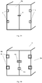
Figs. 3A and 3B show an electronic seal system of the present invention. - Now, detailed references are provided for the embodiments of the present invention, and examples thereof are illustrated in the accompanying drawings, in which like numbers all represent like elements. To explain the present invention, the embodiments below will be described with reference to the accompanying drawings.
- According to the first embodiment of the present invention, an
electronic seal 11 is provided, for indicating whether a sealedbox 2 is opened. -
Figs. 1A and 1B show an L-shapedelectronic seal 11 of the present invention. Refer toFigs. 1A and 1B . Theelectronic seal 11 comprises an integrally formedhousing 114, which can be formed by an ultrasonic injection molding process, for example. The integratedhousing 114 has the advantage that entering the inside of thehousing 114 will inevitably cause a damaged trace on thehousing 114. In other words, if access to the inside of thehousing 114 is desired, thehousing 114 must be opened or damaged, and a trace will be left on the surface of thehousing 114 in opening or damaging thehousing 114, so inspectors could know the electronic seal has been damaged. The integratedhousing 114 can be prevented from being illegally damaged. The integratedhousing 114 comprises a front face 115 (corresponding to the second surface) and a back face 116 (corresponding to the first surface). Thefront face 115 of thehousing 114 faces outwards, and theback face 116 of thehousing 114 is adapted to contact and fit with the sealed box 2 (corresponding to the attached box). "Fit" refers to that theback face 116 of thehousing 114 is substantially complementary with the surface of thebox 2 to be contacted, so that after theback face 116 of thehousing 114 and the surface of thebox 2 contact and fit with each other, no obvious gap is formed between theback face 116 of thehousing 114 and the surface of thebox 2. Tools such as a blade, a screw driver, etc. or foreign objects cannot enter theback face 116 of thehousing 114, so as to prevent theback face 116 of thehousing 114 from being damaged. - The
electronic seal 11 further comprises at least onemagnet 111 and at least oneHall element 112 paired with the magnet. The magnet and the Hall element are arranged in thehousing 114. The Hall element is adapted to send a warning signal when thehousing 114 of theelectronic seal 11 is opened. - A very strong magnetic attractive force is generated when the
magnet 111 contacts and fits with themetal box 2 such as a steel container, accordingly, theelectronic seal 11 is attached and fixed on the surface of thebox 2 of the container. When theelectronic seal 11 is fixed on the surface of thebox 2, no part of theback face 116 of thehousing 114 of theelectronic seal 11 can be contacted. Theback face 116 of theelectronic seal 11 can be contacted only when theelectronic seal 11 is pried off thebox 2, but in such case, theelectronic seal 11 will send a signal indicating theelectronic seal 11 has left thebox 2. - The
electronic seal 11 comprises at least onemagnet 111 and at least oneHall element 112 paired with the magnet. When themagnet 111 is not attached on themetal box 2, the state of theHall element 112 is "0"; and when themagnet 111 is attached on themetal box 2, themagnet 111 and theHall element 112 interact with each other, so that the state of theHall element 112 is "I". After theelectronic seal 11 is installed on thebox 2, the state of theHall element 112 is recorded; and when the state of theHall element 112 changes, theHall element 112 will send out state information through an antenna. In such a way, an operator can obtain change of the state of theelectronic seal 11 and information that theelectronic seal 11 is moved. The magnet of the electronic seal is not only adapted to attach the electronic seal to the metal box through magnetic attractive force, but also reflect the state of the electronic seal through interaction with the Hall element. - Accordingly, as shown in
Figs. 3A and 3B , in some cases, adoor 20 may be removed by cutting an L-shaped hinge 1, which is welded on thebox 2 and connects thedoor 20 and aside edge 21, for example, of the box 2 (a part of the hinge 1 is welded on thedoor 20, the other part is welded on a side of thebox 2 orthogonal to the door 20), and after illegal movement is completed, the hinge 1 is welded on thebox 2 again, so as to avoid that thedoor 20 is found be opened. In order to prevent the hinge 1 from being damaged, theelectronic seal 11 may cover the hinge 1 and protect the hinge 1 from contact or removal, thereby preventing criminal behaviors. Such anelectronic seal 11 may be in the shape of L as shown inFigs. 1A and 1B . As shown inFigs. 3A and 3B , theelectronic seal 11 covers the hinge 1 in two directions of the L-shaped hinge perpendicular to each other to be attached to thebox 2, thereby protecting the hinge 1. Any action damaging the hinge must be performed by removing theelectronic seal 11, and illegally removing theelectronic seal 11 will trigger warning. Alternatively, theelectronic seal 11 may further comprise one or moreadditional Hall elements 117. The additional Hall elements send a signal indicating thehousing 114 is damaged when thehousing 114 of theelectronic seal 11 is damaged. Due to theadditional Hall elements 117, the integrally formedhousing 114 cannot be damaged, and theelectronic seal 11 itself is monitored. For example, theadditional Hall elements 117 are distributed in the electronic seal, and mutually cooperate with magnet matched with the same and arranged in the electronic seal, and when thehousing 114 of the electronic seal is damaged, theadditional Hall elements 117 send a signal. Favorably, theadditional Hall elements 117 mutually cooperate with themagnet 111, which is arranged in the electronic seal and adapted to determine whether the electronic seal leaves the box. Thus, there's no need of arranging additional or special magnet or magnets in the electronic seal, and themagnet 111 can cooperate with theadditional Hall elements 117 and at the same time protect the housing of the electronic seal through cooperation with theadditional Hall elements 117. Alternatively, theelectronic seal 11 may further comprise one or more additional optical elements. The additional optical elements are arranged at one or more positions in the electronic seal, and these additional optical elements may comprise, for example, a optical sensor. When the electronic seal is damaged and external light irradiates to the inside of the electronic seal, light is sensed by an optical sensor, and then a signal is sent for warning. The optical sensor may comprise an infrared sensor, an ultraviolet sensor, a broadband optical sensor or the like, for example. The optical sensor may be an active optical sensor. - Alternatively, the
electronic seal 11 may further comprise one or more additional optical elements and one or moreadditional Hall elements 117. Such a structure is favorable and can provide redundant protection. - The
electronic seal 11 comprises twomagnets 111 and twoHall elements 112 respectively paired with the two magnets. Twomagnets 111 and twoHall elements 112 are respectively disposed at positions adjacent to two end portions of theelectronic seal 11, for example, as shown inFig. 1B . One of the functions of themagnets 111 is fixing theelectronic seal 11. The twomagnets 111 respectively are arranged adjacent to two ends of theelectronic seal 11 may maintain theelectronic seal 11 to be fixed on thebox 2 in a balancing manner. At the same time, themagnets 111 are also adapted to form the warning together with theHall elements 112. When themagnet 111 is disposed together with theHall elements 112 paired with it, and themagnet 111 is attached on thebox 2 due to magnetic property, the state of theHall element 112 is 1; and when themagnet 111 leaves thebox 2, the state of theHall element 112 is changed to be 0, and is sent out. Accordingly, the state of theelectronic seal 11 may be determined. - In the first embodiment, the
electronic seal 11 further comprises amagnet locking device 113. The extending and retracting of themagnet 111 is controlled by virtue of themagnet locking device 113. Themagnet locking device 113 is adapted to drive themagnet 111 to contact or leave thebox 2. Themagnet locking device 113 comprises a lock plunger adapted to be operated on the front face 115 (corresponding to the second surface), and a user drives saidmagnet 111 to contact or leave thebox 2 by rotating said lock plunger from the second surface. The second surface is thefront face 115 of thehousing 114 of theelectronic seal 11 facing outwards. Arranging themagnet locking device 113 on the face facing outwards allows an operator to control extending and retracting of themagnet 111 from thefront face 115 of thehousing 114. For example, if the lock plunger of themagnet locking device 113 is rotated from the second surface, the lock plunger will extend forwards or retract backwards, and the lock plunger pushes or pulls themagnet 111, so as to drive themagnet 111. - The
electronic seal 11 comprises an antenna, for transmitting a signal indicating the state of theHall element 112. - The
electronic seal 11 comprises a power supply, for providing power for theHall element 112 and additional Hall elements. - Preferably, the
electronic seal 11 comprises a switch for turning on/off the power supply. - Preferably, the switch of the
electronic seal 11 is a press-in trigger switch, configured to be pressed in for turning on the power supply when theelectronic seal 11 is installed on thebox 2. - Alternatively, the electronic seal further comprises an electronic control switch, which can be a power supply switch or other electronic switch in parallel with the press-in trigger switch and controlled by program, thereby ensuring that the electronic seal will not power down in abnormal conditions.
- According to the second embodiment of the present invention, an
electronic seal 12 is provided, for indicating whether a sealedbox 2 is opened. -
Figs. 2A and 2B show a line-typeelectronic seal 12 of the present invention. Refer toFigs. 2A and 2B . Comparing the line-typeelectronic seal 12 of the second embodiment with the L-shapedelectronic seal 11 of the first embodiment, the housings of the two are different in shape. - The line-type
electronic seal 12 comprises an integrally formed line-type housing 124. Thehousing 124 comprises afront face 125 and aback face 126. Theelectronic seal 12 further comprises at least onemagnet 121 and at least oneHall element 122 paired with themagnet 121. Themagnet 121 and theHall element 122 are arranged in thehousing 124. The Hall element is adapted to send a warning signal when thehousing 124 of theelectronic seal 12 is opened. Theelectronic seal 12 further comprises amagnet locking device 123. The extending and retracting of themagnet 121 is controlled by virtue of themagnet locking device 123. Theelectronic seal 12 may further comprise one or moreadditional Hall elements 127 and/or one or more additional optical elements. Theelectronic seal 12 may further comprise an antenna, a power supply, a switch, an electronic control switch and the like. - As for others not illustrated in the second embodiment, please refer to relevant contents of the first embodiment. For example, reference to relevant description about the
housing 114 in the first embodiment may be made with respect to thehousing 124 and thefront face 125 and back face 126 thereof, except for its different shape from thehousing 114. For the magnet ormagnets 121, the Hall element orelements 122, themagnet locking device 123, theadditional Hall elements 127, the additional optical elements, the antenna, the power supply, the switch, the electronic control switch and the like, reference may be correspondingly made to relevant description about themagnet 111, theHall element 112, themagnetic locking device 113, theadditional Hall elements 117, the additional optical elements, the antenna, the power supply, the switch, the electronic control switch and the like in the first embodiment. Thus, according to the embodiment of the present invention, as shown inFigs. 3A and 3B , when theelectronic seal 12 is attached to thedoor 20, for example, crossing a slot between door leaves of thedoor 20, thedoor 20 can not be opened. Because if once thedoor 20 is opened, theelectronic seal 12 cannot well fit with thedoor 20, a signal indicating theelectronic seal 12 leaves thebox 2 is sent once theelectronic seal 12 leaves thebox 2, and then a customs officer or other relevant person, for example, could know theelectronic seal 12 is moved and thedoor 20 is opened. Suchelectronic seal 12 may be in the shape of a strip, for example, a line-type shape as shown inFigs. 2A and 2B . Thedoor 20 may be closed by enabling the electronic seal to cross the slot between door leaves of thedoor 20. Theelectronic seal 12 may further cover alock 3 for locking the door, as shown inFigs. 3A and 3B . - Refer to
Fig. 3B . According to the third embodiment of the present invention, an electronic seal system is provided, comprising acustoms lock 13 and at least one electronic seal described above. In this embodiment, each electronic seal establishes data communication with said customs lock 13 adapted to send information of the electronic seal to users. The customs lock 13 is configured to store state information of the electronic seal, for example, the information including the number, position and state information of the electronic seal. In this embodiment, said customs lock 13 is configured to activate the electronic seal. - According to the embodiments of the present invention, it should be known by a person skilled in the art the Hall element is merely a form of the present invention, and other elements adapted to detect the change of magnetic field or the occurrence of damage all can replace the Hall element under the teaching of the present invention. The present invention is specially illustrated and described with reference to typical embodiments of the present invention, however, it should be understood by those of ordinary skill in the art that various changes in forms and details could be made to these embodiments without departing from the spirit and scope of the present invention defined by the appended claims.
Claims (15)
- An electronic seal for indicating whether an attached box is opened, wherein the electronic seal comprises a housing having a first surface and a second surface, the electronic seal further comprises at least one magnet and at least one Hall element paired with the magnet, and the magnet and the Hall element are arranged in the housing,
wherein the first surface is adapted to contact and fit with the box, and after the magnet is attached on the box, the magnet and the Hall element cooperate to send a signal that the electronic seal is moved, when the electronic seal leaves the box. - The electronic seal of claim 1, wherein the magnet is adapted to contact and attach on the box, so as to fix the electronic seal on the box.
- The electronic seal of claim 1, wherein the housing is an integrally formed housing.
- The electronic seal of claim 1, wherein the electronic seal further comprises additional Hall element arranged in the electronic seal and for sending a warning signal when the housing of the electronic seal is opened.
- The electronic seal of claim 1, wherein the electronic seal further comprises additional optical sensor arranged in the electronic seal and for sending a warning signal due to light received when the housing of the electronic seal is opened.
- The electronic seal of claim 1, wherein the electronic seal is line-type seal for crossing a gap between door leaves of a door of the box to attach on the door, and when the door is opened, the electronic seal is separated from the door and sends a signal that the electronic seal leaves the door.
- The electronic seal of claim 1, wherein the electronic seal is L-shaped for covering a hinge connecting a door of the box and the box to completely cover a L-shaped hinge in two directions of the L-shaped hinge, so as to prevent from contacting the hinge.
- The electronic seal of claim 1, wherein the electronic seal comprises two magnets and two Hall elements respectively paired with the two magnets, and the two magnets and the two Hall elements are respectively disposed at two positions adjacent to two end portions of the electronic seal.
- The electronic seal of claim 1, wherein the electronic seal comprises a magnet locking device adapted to drive the magnet to extend out to contact the box or retract to leave the box, the magnet locking device comprises a lock plunger adapted to be operated on the second surface, and a user drives the magnet to contact or leave the box by rotating the lock plunger from the second surface.
- The electronic seal of claim 1, wherein the electronic seal comprises an antenna for transmitting a signal from the Hall element.
- The electronic seal of claim 1, wherein the electronic seal comprises a power supply for providing power for the Hall element and additional Hall element.
- The electronic seal of claim 11, wherein the electronic seal comprises a switch for turning on and off the power supply.
- The electronic seal of claim 12, wherein the switch is a press-in trigger switch, configured to be pressed in when the electronic seal is installed on the box, so as to turn on the power supply.
- An electronic seal system, comprising a customs lock and at least one electronic seal of claim 1, wherein each electronic seal establishes data communication with the customs lock which sends information of the electronic seal to users.
- The electronic seal system of claim 14, wherein the customs lock is configured to activate the electronic seal and store information of the electronic seal, the information includes the number, position and state information of the electronic seal.
Priority Applications (1)
| Application Number | Priority Date | Filing Date | Title |
|---|---|---|---|
| PL16823773T PL3323755T3 (en) | 2015-07-14 | 2016-06-27 | Electronic seal and electronic sealing system |
Applications Claiming Priority (2)
| Application Number | Priority Date | Filing Date | Title |
|---|---|---|---|
| CN201510412434.7A CN104989184B (en) | 2015-07-14 | 2015-07-14 | E-seals and e-seals system |
| PCT/CN2016/087235 WO2017008626A1 (en) | 2015-07-14 | 2016-06-27 | Electronic seal and electronic sealing system |
Publications (3)
| Publication Number | Publication Date |
|---|---|
| EP3323755A1 true EP3323755A1 (en) | 2018-05-23 |
| EP3323755A4 EP3323755A4 (en) | 2019-03-06 |
| EP3323755B1 EP3323755B1 (en) | 2020-11-18 |
Family
ID=54301055
Family Applications (1)
| Application Number | Title | Priority Date | Filing Date |
|---|---|---|---|
| EP16823773.3A Active EP3323755B1 (en) | 2015-07-14 | 2016-06-27 | Electronic seal and electronic sealing system |
Country Status (6)
| Country | Link |
|---|---|
| EP (1) | EP3323755B1 (en) |
| CN (1) | CN104989184B (en) |
| MX (1) | MX373839B (en) |
| MY (1) | MY188542A (en) |
| PL (1) | PL3323755T3 (en) |
| WO (1) | WO2017008626A1 (en) |
Families Citing this family (3)
| Publication number | Priority date | Publication date | Assignee | Title |
|---|---|---|---|---|
| CN104989184B (en) * | 2015-07-14 | 2018-02-16 | 同方威视技术股份有限公司 | E-seals and e-seals system |
| CN105955106A (en) * | 2016-04-29 | 2016-09-21 | 深圳市久通物联科技股份有限公司 | Container monitoring device and monitoring implementation method thereof |
| CN111502419A (en) * | 2020-05-11 | 2020-08-07 | 北京中经天平科技有限公司 | Electronic seal |
Family Cites Families (14)
| Publication number | Priority date | Publication date | Assignee | Title |
|---|---|---|---|---|
| CN101866510B (en) * | 2002-12-31 | 2011-09-07 | 迪布尔特有限公司 | ATM currency cassette arrangement and operating method |
| CN1272224C (en) * | 2003-07-02 | 2006-08-30 | 中国国际海运集装箱(集团)股份有限公司 | Device of electronic box with built in inductive contact |
| JP2006039302A (en) * | 2004-07-28 | 2006-02-09 | Nippon Signal Co Ltd:The | Ic tag for sealing, document file, and document file management system |
| CN1884012B (en) * | 2005-06-22 | 2011-08-03 | 中国国际海运集装箱(集团)股份有限公司 | Integrated container seal |
| CN2846341Y (en) * | 2005-08-09 | 2006-12-13 | 上海锐帆信息科技有限公司 | Electronic seal for container |
| CN101074064B (en) * | 2006-05-17 | 2011-01-05 | 中国国际海运集装箱(集团)股份有限公司 | Safety monitoring device and system for container |
| CN201080344Y (en) * | 2007-06-11 | 2008-07-02 | 中国国际海运集装箱(集团)股份有限公司 | Refrigerated container |
| CN101667362B (en) * | 2008-09-03 | 2011-12-14 | 中国国际海运集装箱(集团)股份有限公司 | Electronic seal |
| DE102010061069A1 (en) * | 2010-12-07 | 2012-06-14 | Wincor Nixdorf International Gmbh | Cashbox with electronic seal |
| TWM457051U (en) * | 2012-09-11 | 2013-07-11 | Li-shi LIAO | Blocking-detection energy-saving device for electromagnetic door lock |
| WO2014142826A1 (en) * | 2013-03-13 | 2014-09-18 | Sea Box Inc. | Collapsible stackable container with reusable seals |
| US9221599B2 (en) * | 2013-03-13 | 2015-12-29 | Sea Box Inc. | Collapsible stackable shipping container with reusable seals |
| CN104989184B (en) * | 2015-07-14 | 2018-02-16 | 同方威视技术股份有限公司 | E-seals and e-seals system |
| CN204782324U (en) * | 2015-07-14 | 2015-11-18 | 同方威视技术股份有限公司 | Electronic seal and electronic seal system |
-
2015
- 2015-07-14 CN CN201510412434.7A patent/CN104989184B/en active Active
-
2016
- 2016-06-27 WO PCT/CN2016/087235 patent/WO2017008626A1/en not_active Ceased
- 2016-06-27 PL PL16823773T patent/PL3323755T3/en unknown
- 2016-06-27 MY MYPI2016702857A patent/MY188542A/en unknown
- 2016-06-27 EP EP16823773.3A patent/EP3323755B1/en active Active
- 2016-06-27 MX MX2016010490A patent/MX373839B/en active IP Right Grant
Also Published As
| Publication number | Publication date |
|---|---|
| MX373839B (en) | 2020-03-25 |
| EP3323755B1 (en) | 2020-11-18 |
| WO2017008626A1 (en) | 2017-01-19 |
| CN104989184A (en) | 2015-10-21 |
| MX2016010490A (en) | 2017-07-26 |
| PL3323755T3 (en) | 2021-05-17 |
| MY188542A (en) | 2021-12-21 |
| CN104989184B (en) | 2018-02-16 |
| EP3323755A4 (en) | 2019-03-06 |
Similar Documents
| Publication | Publication Date | Title |
|---|---|---|
| CA2740861C (en) | Sealing device | |
| EP3073410B1 (en) | Usb link lock device | |
| CN106437304B (en) | Security system | |
| US11238184B2 (en) | Secure vehicle control unit | |
| US20090321302A1 (en) | Protection device for an electronic card | |
| EP3323755B1 (en) | Electronic seal and electronic sealing system | |
| US10216968B2 (en) | Card reader | |
| CA2942419C (en) | A position monitoring device | |
| JP6117229B2 (en) | Device for controlling the operation of the machine, locking insert for such a device and the accompanying operating method | |
| EP3613202B1 (en) | Port security device for computing devices and method of operating such | |
| JP2021100113A (en) | Electric device and electric device system including electric device | |
| CN1884012A (en) | Integrated container customs seal | |
| WO2016045025A1 (en) | Terminal | |
| US20100050535A1 (en) | Detector of attempt to break a lock, lock, door and alarm system comprising such a detector | |
| EP1770735B1 (en) | Safety switch | |
| KR20200099283A (en) | Apparatus for front door stopper of experimental equipment | |
| CN216491550U (en) | Password input device storage device for counter | |
| US11828085B1 (en) | System for lock keyway access monitoring | |
| KR101104769B1 (en) | Alarm generating unit for goods storage box | |
| AU2014284118A1 (en) | Security device | |
| JP2004076416A (en) | Dustproof and waterproof cap of keyhole | |
| CN210666774U (en) | Financial terminal device with prevent tearing open protection mechanism | |
| JP5156884B2 (en) | Safety magnetic sensor | |
| US20190182973A1 (en) | Housing with secure opening | |
| KR102079656B1 (en) | Electric cable protection device for laying road |
Legal Events
| Date | Code | Title | Description |
|---|---|---|---|
| STAA | Information on the status of an ep patent application or granted ep patent |
Free format text: STATUS: THE INTERNATIONAL PUBLICATION HAS BEEN MADE |
|
| PUAI | Public reference made under article 153(3) epc to a published international application that has entered the european phase |
Free format text: ORIGINAL CODE: 0009012 |
|
| STAA | Information on the status of an ep patent application or granted ep patent |
Free format text: STATUS: REQUEST FOR EXAMINATION WAS MADE |
|
| 17P | Request for examination filed |
Effective date: 20170929 |
|
| AK | Designated contracting states |
Kind code of ref document: A1 Designated state(s): AL AT BE BG CH CY CZ DE DK EE ES FI FR GB GR HR HU IE IS IT LI LT LU LV MC MK MT NL NO PL PT RO RS SE SI SK SM TR |
|
| AX | Request for extension of the european patent |
Extension state: BA ME |
|
| DAV | Request for validation of the european patent (deleted) | ||
| DAX | Request for extension of the european patent (deleted) | ||
| A4 | Supplementary search report drawn up and despatched |
Effective date: 20190205 |
|
| RIC1 | Information provided on ipc code assigned before grant |
Ipc: B65D 90/48 20060101AFI20190129BHEP Ipc: G09F 3/03 20060101ALI20190129BHEP |
|
| GRAP | Despatch of communication of intention to grant a patent |
Free format text: ORIGINAL CODE: EPIDOSNIGR1 |
|
| STAA | Information on the status of an ep patent application or granted ep patent |
Free format text: STATUS: GRANT OF PATENT IS INTENDED |
|
| INTG | Intention to grant announced |
Effective date: 20200626 |
|
| GRAS | Grant fee paid |
Free format text: ORIGINAL CODE: EPIDOSNIGR3 |
|
| GRAA | (expected) grant |
Free format text: ORIGINAL CODE: 0009210 |
|
| STAA | Information on the status of an ep patent application or granted ep patent |
Free format text: STATUS: THE PATENT HAS BEEN GRANTED |
|
| AK | Designated contracting states |
Kind code of ref document: B1 Designated state(s): AL AT BE BG CH CY CZ DE DK EE ES FI FR GB GR HR HU IE IS IT LI LT LU LV MC MK MT NL NO PL PT RO RS SE SI SK SM TR |
|
| REG | Reference to a national code |
Ref country code: GB Ref legal event code: FG4D |
|
| REG | Reference to a national code |
Ref country code: CH Ref legal event code: EP |
|
| REG | Reference to a national code |
Ref country code: IE Ref legal event code: FG4D |
|
| REG | Reference to a national code |
Ref country code: DE Ref legal event code: R096 Ref document number: 602016048235 Country of ref document: DE |
|
| REG | Reference to a national code |
Ref country code: AT Ref legal event code: REF Ref document number: 1335537 Country of ref document: AT Kind code of ref document: T Effective date: 20201215 |
|
| REG | Reference to a national code |
Ref country code: AT Ref legal event code: MK05 Ref document number: 1335537 Country of ref document: AT Kind code of ref document: T Effective date: 20201118 |
|
| REG | Reference to a national code |
Ref country code: NL Ref legal event code: MP Effective date: 20201118 |
|
| PG25 | Lapsed in a contracting state [announced via postgrant information from national office to epo] |
Ref country code: GR Free format text: LAPSE BECAUSE OF FAILURE TO SUBMIT A TRANSLATION OF THE DESCRIPTION OR TO PAY THE FEE WITHIN THE PRESCRIBED TIME-LIMIT Effective date: 20210219 Ref country code: FI Free format text: LAPSE BECAUSE OF FAILURE TO SUBMIT A TRANSLATION OF THE DESCRIPTION OR TO PAY THE FEE WITHIN THE PRESCRIBED TIME-LIMIT Effective date: 20201118 Ref country code: PT Free format text: LAPSE BECAUSE OF FAILURE TO SUBMIT A TRANSLATION OF THE DESCRIPTION OR TO PAY THE FEE WITHIN THE PRESCRIBED TIME-LIMIT Effective date: 20210318 Ref country code: RS Free format text: LAPSE BECAUSE OF FAILURE TO SUBMIT A TRANSLATION OF THE DESCRIPTION OR TO PAY THE FEE WITHIN THE PRESCRIBED TIME-LIMIT Effective date: 20201118 Ref country code: NO Free format text: LAPSE BECAUSE OF FAILURE TO SUBMIT A TRANSLATION OF THE DESCRIPTION OR TO PAY THE FEE WITHIN THE PRESCRIBED TIME-LIMIT Effective date: 20210218 |
|
| PG25 | Lapsed in a contracting state [announced via postgrant information from national office to epo] |
Ref country code: AT Free format text: LAPSE BECAUSE OF FAILURE TO SUBMIT A TRANSLATION OF THE DESCRIPTION OR TO PAY THE FEE WITHIN THE PRESCRIBED TIME-LIMIT Effective date: 20201118 Ref country code: LV Free format text: LAPSE BECAUSE OF FAILURE TO SUBMIT A TRANSLATION OF THE DESCRIPTION OR TO PAY THE FEE WITHIN THE PRESCRIBED TIME-LIMIT Effective date: 20201118 Ref country code: IS Free format text: LAPSE BECAUSE OF FAILURE TO SUBMIT A TRANSLATION OF THE DESCRIPTION OR TO PAY THE FEE WITHIN THE PRESCRIBED TIME-LIMIT Effective date: 20210318 Ref country code: BG Free format text: LAPSE BECAUSE OF FAILURE TO SUBMIT A TRANSLATION OF THE DESCRIPTION OR TO PAY THE FEE WITHIN THE PRESCRIBED TIME-LIMIT Effective date: 20210218 Ref country code: SE Free format text: LAPSE BECAUSE OF FAILURE TO SUBMIT A TRANSLATION OF THE DESCRIPTION OR TO PAY THE FEE WITHIN THE PRESCRIBED TIME-LIMIT Effective date: 20201118 |
|
| REG | Reference to a national code |
Ref country code: LT Ref legal event code: MG9D |
|
| PG25 | Lapsed in a contracting state [announced via postgrant information from national office to epo] |
Ref country code: HR Free format text: LAPSE BECAUSE OF FAILURE TO SUBMIT A TRANSLATION OF THE DESCRIPTION OR TO PAY THE FEE WITHIN THE PRESCRIBED TIME-LIMIT Effective date: 20201118 |
|
| PG25 | Lapsed in a contracting state [announced via postgrant information from national office to epo] |
Ref country code: LT Free format text: LAPSE BECAUSE OF FAILURE TO SUBMIT A TRANSLATION OF THE DESCRIPTION OR TO PAY THE FEE WITHIN THE PRESCRIBED TIME-LIMIT Effective date: 20201118 Ref country code: SM Free format text: LAPSE BECAUSE OF FAILURE TO SUBMIT A TRANSLATION OF THE DESCRIPTION OR TO PAY THE FEE WITHIN THE PRESCRIBED TIME-LIMIT Effective date: 20201118 Ref country code: EE Free format text: LAPSE BECAUSE OF FAILURE TO SUBMIT A TRANSLATION OF THE DESCRIPTION OR TO PAY THE FEE WITHIN THE PRESCRIBED TIME-LIMIT Effective date: 20201118 Ref country code: CZ Free format text: LAPSE BECAUSE OF FAILURE TO SUBMIT A TRANSLATION OF THE DESCRIPTION OR TO PAY THE FEE WITHIN THE PRESCRIBED TIME-LIMIT Effective date: 20201118 Ref country code: RO Free format text: LAPSE BECAUSE OF FAILURE TO SUBMIT A TRANSLATION OF THE DESCRIPTION OR TO PAY THE FEE WITHIN THE PRESCRIBED TIME-LIMIT Effective date: 20201118 Ref country code: SK Free format text: LAPSE BECAUSE OF FAILURE TO SUBMIT A TRANSLATION OF THE DESCRIPTION OR TO PAY THE FEE WITHIN THE PRESCRIBED TIME-LIMIT Effective date: 20201118 |
|
| REG | Reference to a national code |
Ref country code: DE Ref legal event code: R097 Ref document number: 602016048235 Country of ref document: DE |
|
| PG25 | Lapsed in a contracting state [announced via postgrant information from national office to epo] |
Ref country code: DK Free format text: LAPSE BECAUSE OF FAILURE TO SUBMIT A TRANSLATION OF THE DESCRIPTION OR TO PAY THE FEE WITHIN THE PRESCRIBED TIME-LIMIT Effective date: 20201118 |
|
| PLBE | No opposition filed within time limit |
Free format text: ORIGINAL CODE: 0009261 |
|
| STAA | Information on the status of an ep patent application or granted ep patent |
Free format text: STATUS: NO OPPOSITION FILED WITHIN TIME LIMIT |
|
| 26N | No opposition filed |
Effective date: 20210819 |
|
| PG25 | Lapsed in a contracting state [announced via postgrant information from national office to epo] |
Ref country code: NL Free format text: LAPSE BECAUSE OF FAILURE TO SUBMIT A TRANSLATION OF THE DESCRIPTION OR TO PAY THE FEE WITHIN THE PRESCRIBED TIME-LIMIT Effective date: 20201118 Ref country code: IT Free format text: LAPSE BECAUSE OF FAILURE TO SUBMIT A TRANSLATION OF THE DESCRIPTION OR TO PAY THE FEE WITHIN THE PRESCRIBED TIME-LIMIT Effective date: 20201118 Ref country code: AL Free format text: LAPSE BECAUSE OF FAILURE TO SUBMIT A TRANSLATION OF THE DESCRIPTION OR TO PAY THE FEE WITHIN THE PRESCRIBED TIME-LIMIT Effective date: 20201118 |
|
| PG25 | Lapsed in a contracting state [announced via postgrant information from national office to epo] |
Ref country code: SI Free format text: LAPSE BECAUSE OF FAILURE TO SUBMIT A TRANSLATION OF THE DESCRIPTION OR TO PAY THE FEE WITHIN THE PRESCRIBED TIME-LIMIT Effective date: 20201118 |
|
| REG | Reference to a national code |
Ref country code: DE Ref legal event code: R119 Ref document number: 602016048235 Country of ref document: DE |
|
| PG25 | Lapsed in a contracting state [announced via postgrant information from national office to epo] |
Ref country code: MC Free format text: LAPSE BECAUSE OF FAILURE TO SUBMIT A TRANSLATION OF THE DESCRIPTION OR TO PAY THE FEE WITHIN THE PRESCRIBED TIME-LIMIT Effective date: 20201118 Ref country code: ES Free format text: LAPSE BECAUSE OF FAILURE TO SUBMIT A TRANSLATION OF THE DESCRIPTION OR TO PAY THE FEE WITHIN THE PRESCRIBED TIME-LIMIT Effective date: 20201118 |
|
| REG | Reference to a national code |
Ref country code: CH Ref legal event code: PL |
|
| GBPC | Gb: european patent ceased through non-payment of renewal fee |
Effective date: 20210627 |
|
| REG | Reference to a national code |
Ref country code: BE Ref legal event code: MM Effective date: 20210630 |
|
| PG25 | Lapsed in a contracting state [announced via postgrant information from national office to epo] |
Ref country code: LU Free format text: LAPSE BECAUSE OF NON-PAYMENT OF DUE FEES Effective date: 20210627 |
|
| PG25 | Lapsed in a contracting state [announced via postgrant information from national office to epo] |
Ref country code: LI Free format text: LAPSE BECAUSE OF NON-PAYMENT OF DUE FEES Effective date: 20210630 Ref country code: IE Free format text: LAPSE BECAUSE OF NON-PAYMENT OF DUE FEES Effective date: 20210627 Ref country code: GB Free format text: LAPSE BECAUSE OF NON-PAYMENT OF DUE FEES Effective date: 20210627 Ref country code: DE Free format text: LAPSE BECAUSE OF NON-PAYMENT OF DUE FEES Effective date: 20220101 Ref country code: CH Free format text: LAPSE BECAUSE OF NON-PAYMENT OF DUE FEES Effective date: 20210630 |
|
| PG25 | Lapsed in a contracting state [announced via postgrant information from national office to epo] |
Ref country code: IS Free format text: LAPSE BECAUSE OF FAILURE TO SUBMIT A TRANSLATION OF THE DESCRIPTION OR TO PAY THE FEE WITHIN THE PRESCRIBED TIME-LIMIT Effective date: 20210318 Ref country code: FR Free format text: LAPSE BECAUSE OF NON-PAYMENT OF DUE FEES Effective date: 20210630 |
|
| PG25 | Lapsed in a contracting state [announced via postgrant information from national office to epo] |
Ref country code: BE Free format text: LAPSE BECAUSE OF NON-PAYMENT OF DUE FEES Effective date: 20210630 |
|
| PG25 | Lapsed in a contracting state [announced via postgrant information from national office to epo] |
Ref country code: CY Free format text: LAPSE BECAUSE OF FAILURE TO SUBMIT A TRANSLATION OF THE DESCRIPTION OR TO PAY THE FEE WITHIN THE PRESCRIBED TIME-LIMIT Effective date: 20201118 |
|
| P01 | Opt-out of the competence of the unified patent court (upc) registered |
Effective date: 20230528 |
|
| PG25 | Lapsed in a contracting state [announced via postgrant information from national office to epo] |
Ref country code: HU Free format text: LAPSE BECAUSE OF FAILURE TO SUBMIT A TRANSLATION OF THE DESCRIPTION OR TO PAY THE FEE WITHIN THE PRESCRIBED TIME-LIMIT; INVALID AB INITIO Effective date: 20160627 |
|
| PG25 | Lapsed in a contracting state [announced via postgrant information from national office to epo] |
Ref country code: MK Free format text: LAPSE BECAUSE OF FAILURE TO SUBMIT A TRANSLATION OF THE DESCRIPTION OR TO PAY THE FEE WITHIN THE PRESCRIBED TIME-LIMIT Effective date: 20201118 |
|
| PG25 | Lapsed in a contracting state [announced via postgrant information from national office to epo] |
Ref country code: TR Free format text: LAPSE BECAUSE OF FAILURE TO SUBMIT A TRANSLATION OF THE DESCRIPTION OR TO PAY THE FEE WITHIN THE PRESCRIBED TIME-LIMIT Effective date: 20201118 |
|
| PG25 | Lapsed in a contracting state [announced via postgrant information from national office to epo] |
Ref country code: MT Free format text: LAPSE BECAUSE OF FAILURE TO SUBMIT A TRANSLATION OF THE DESCRIPTION OR TO PAY THE FEE WITHIN THE PRESCRIBED TIME-LIMIT Effective date: 20201118 |
|
| PGFP | Annual fee paid to national office [announced via postgrant information from national office to epo] |
Ref country code: PL Payment date: 20260616 Year of fee payment: 11 |