EP3323685A1 - Straddled vehicle - Google Patents
Straddled vehicle Download PDFInfo
- Publication number
- EP3323685A1 EP3323685A1 EP17198811.6A EP17198811A EP3323685A1 EP 3323685 A1 EP3323685 A1 EP 3323685A1 EP 17198811 A EP17198811 A EP 17198811A EP 3323685 A1 EP3323685 A1 EP 3323685A1
- Authority
- EP
- European Patent Office
- Prior art keywords
- piping
- connector
- hydraulic unit
- head tube
- vehicle
- Prior art date
- Legal status (The legal status is an assumption and is not a legal conclusion. Google has not performed a legal analysis and makes no representation as to the accuracy of the status listed.)
- Granted
Links
Images







Classifications
-
- B—PERFORMING OPERATIONS; TRANSPORTING
- B60—VEHICLES IN GENERAL
- B60T—VEHICLE BRAKE CONTROL SYSTEMS OR PARTS THEREOF; BRAKE CONTROL SYSTEMS OR PARTS THEREOF, IN GENERAL; ARRANGEMENT OF BRAKING ELEMENTS ON VEHICLES IN GENERAL; PORTABLE DEVICES FOR PREVENTING UNWANTED MOVEMENT OF VEHICLES; VEHICLE MODIFICATIONS TO FACILITATE COOLING OF BRAKES
- B60T8/00—Arrangements for adjusting wheel-braking force to meet varying vehicular or ground-surface conditions, e.g. limiting or varying distribution of braking force
- B60T8/32—Arrangements for adjusting wheel-braking force to meet varying vehicular or ground-surface conditions, e.g. limiting or varying distribution of braking force responsive to a speed condition, e.g. acceleration or deceleration
- B60T8/34—Arrangements for adjusting wheel-braking force to meet varying vehicular or ground-surface conditions, e.g. limiting or varying distribution of braking force responsive to a speed condition, e.g. acceleration or deceleration having a fluid pressure regulator responsive to a speed condition
- B60T8/36—Arrangements for adjusting wheel-braking force to meet varying vehicular or ground-surface conditions, e.g. limiting or varying distribution of braking force responsive to a speed condition, e.g. acceleration or deceleration having a fluid pressure regulator responsive to a speed condition including a pilot valve responding to an electromagnetic force
- B60T8/3615—Electromagnetic valves specially adapted for anti-lock brake and traction control systems
- B60T8/3675—Electromagnetic valves specially adapted for anti-lock brake and traction control systems integrated in modulator units
- B60T8/368—Electromagnetic valves specially adapted for anti-lock brake and traction control systems integrated in modulator units combined with other mechanical components, e.g. pump units, master cylinders
- B60T8/3685—Electromagnetic valves specially adapted for anti-lock brake and traction control systems integrated in modulator units combined with other mechanical components, e.g. pump units, master cylinders characterised by the mounting of the modulator unit onto the vehicle
-
- B—PERFORMING OPERATIONS; TRANSPORTING
- B62—LAND VEHICLES FOR TRAVELLING OTHERWISE THAN ON RAILS
- B62K—CYCLES; CYCLE FRAMES; CYCLE STEERING DEVICES; RIDER-OPERATED TERMINAL CONTROLS SPECIALLY ADAPTED FOR CYCLES; CYCLE AXLE SUSPENSIONS; CYCLE SIDECARS, FORECARS, OR THE LIKE
- B62K19/00—Cycle frames
- B62K19/30—Frame parts shaped to receive other cycle parts or accessories
- B62K19/38—Frame parts shaped to receive other cycle parts or accessories for attaching brake members
-
- B—PERFORMING OPERATIONS; TRANSPORTING
- B60—VEHICLES IN GENERAL
- B60T—VEHICLE BRAKE CONTROL SYSTEMS OR PARTS THEREOF; BRAKE CONTROL SYSTEMS OR PARTS THEREOF, IN GENERAL; ARRANGEMENT OF BRAKING ELEMENTS ON VEHICLES IN GENERAL; PORTABLE DEVICES FOR PREVENTING UNWANTED MOVEMENT OF VEHICLES; VEHICLE MODIFICATIONS TO FACILITATE COOLING OF BRAKES
- B60T8/00—Arrangements for adjusting wheel-braking force to meet varying vehicular or ground-surface conditions, e.g. limiting or varying distribution of braking force
-
- B—PERFORMING OPERATIONS; TRANSPORTING
- B60—VEHICLES IN GENERAL
- B60T—VEHICLE BRAKE CONTROL SYSTEMS OR PARTS THEREOF; BRAKE CONTROL SYSTEMS OR PARTS THEREOF, IN GENERAL; ARRANGEMENT OF BRAKING ELEMENTS ON VEHICLES IN GENERAL; PORTABLE DEVICES FOR PREVENTING UNWANTED MOVEMENT OF VEHICLES; VEHICLE MODIFICATIONS TO FACILITATE COOLING OF BRAKES
- B60T8/00—Arrangements for adjusting wheel-braking force to meet varying vehicular or ground-surface conditions, e.g. limiting or varying distribution of braking force
- B60T8/32—Arrangements for adjusting wheel-braking force to meet varying vehicular or ground-surface conditions, e.g. limiting or varying distribution of braking force responsive to a speed condition, e.g. acceleration or deceleration
- B60T8/321—Arrangements for adjusting wheel-braking force to meet varying vehicular or ground-surface conditions, e.g. limiting or varying distribution of braking force responsive to a speed condition, e.g. acceleration or deceleration deceleration
- B60T8/3225—Systems specially adapted for single-track vehicles, e.g. motorcycles
-
- B—PERFORMING OPERATIONS; TRANSPORTING
- B62—LAND VEHICLES FOR TRAVELLING OTHERWISE THAN ON RAILS
- B62L—BRAKES SPECIALLY ADAPTED FOR CYCLES
- B62L3/00—Brake-actuating mechanisms; Arrangements thereof
- B62L3/02—Brake-actuating mechanisms; Arrangements thereof for control by a hand lever
- B62L3/023—Brake-actuating mechanisms; Arrangements thereof for control by a hand lever acting on fluid pressure systems
Definitions
- This invention relates to a straddled vehicle having a hydraulic device.
- Japanese Unexamined Patent Publication No. 2013-47018 discloses a two-wheeled motor vehicle which employs an ABS (antilock brake system).
- the ABS includes a hydraulic unit for regulating the hydraulic pressure of a brake fluid.
- the hydraulic unit is fixed to a head tube.
- a front cover is arranged forward, rightward and leftward of the hydraulic unit.
- the hydraulic unit regulates the hydraulic pressure of a front brake, and the hydraulic pressure of a rear brake.
- the hydraulic unit is connected to four pipes.
- the four pipes are a front upstream pipe, a front downstream pipe, a rear upstream pipe, and a rear downstream pipe.
- the front upstream pipe connects a front master brake and the hydraulic unit.
- the front downstream pipe connects the hydraulic unit and the front brake.
- the rear upstream pipe connects a rear master cylinder and the hydraulic unit.
- the rear downstream pipe connects the hydraulic unit and the rear brake.
- the front upstream pipe and rear upstream pipe both extend in the same direction (e.g. forward) from the hydraulic unit.
- the front downstream pipe and rear downstream pipe both extend in the same direction (e.g. upward) from the hydraulic unit.
- the front upstream pipe and front downstream pipe are arranged to protrude to a large extent leftward of the hydraulic unit.
- the head tube and front cover have only a narrow space in between.
- headlights and the like are attached to the front cover, the space between the head tube and the front cover, headlights and the like is narrow.
- the front cover and the members (e.g. the headlights and the like) attached to the front cover are hereinafter collectively called "appearance constituent members".
- the hydraulic unit is installed in the space between the head tube and appearance constituent members.
- the hydraulic unit needs a relatively large installation space.
- the components (“other components” hereinafter) other than the hydraulic unit are also installed in the space between the head tube and appearance constituent members. It is therefore difficult to arrange the hydraulic unit and other components appropriately between the head tube and appearance constituent members.
- the hydraulic unit It has been considered to place the hydraulic unit to have the center thereof in a transverse direction of the straddled vehicle located on a vehicle center plane.
- the vehicle center plane is an imaginary plane which passes through the center of the straddled vehicle, and extends perpendicular to the transverse direction of the straddled vehicle.
- This arrangement can form one space rightward of the hydraulic unit and another space leftward of the hydraulic unit.
- These two spaces are divided by the hydraulic unit. Since the center of the hydraulic unit in the transverse direction is located on the vehicle center plane, the two spaces have substantially the same size.
- the narrow space between the head tube and appearance constituent members is divided substantially evenly into two spaces. Each of the two spaces is therefore relatively small. As a result, it may be difficult to arrange the other components in each space.
- a straddled vehicle comprises:
- the center of the hydraulic unit in the transverse direction of the straddled vehicle is located on one side of the vehicle center plane. That is, the center of the hydraulic unit in the transverse direction is not on the vehicle center plane, but is shifted from the vehicle center plane. Consequently, a relatively large space can be formed either rightward or leftward of the hydraulic unit.
- the space between the head tube and appearance constituent member can therefore easily accommodate, along with the hydraulic unit, components other than the hydraulic unit.
- the hydraulic unit can be placed efficiently in the space between the head tube and appearance constituent member.
- the hydraulic unit includes the first connector and second connector.
- the second connector may be disposed in the same position as the first connector in the transverse direction of the straddled vehicle. In other words, the position of the second connector in the transverse direction may be the same as the position of the first connector in the transverse direction. Or the second connector may be disposed in a position rightward of the first connector.
- the first piping is connected to the first connector.
- the second piping is connected to the second connector.
- the first piping is further connected to one of the master cylinder and hydraulic brake.
- the second piping is connected to the hydraulic brake.
- the second piping is connected to the master cylinder.
- the first piping has the first end connected to the first connector.
- the first end extends in the first direction from the first connector.
- the first direction includes a component in the transverse direction. In other words, the component in the transverse direction of the first direction is not zero.
- the second piping has the second end connected to the second connector. The second end extends in the second direction from the second connector.
- the second direction includes a component in the transverse direction.
- the component in the transverse direction of the first direction points rightward.
- the component in the transverse direction of the second direction points leftward.
- the first piping and second piping can therefore be arranged appropriately.
- the center of the hydraulic unit in the transverse direction is located leftward of the vehicle center plane, and that the first connector is disposed leftward of the second connector.
- the first connector is disposed closer than the second connector to the appearance constituent member. That is, the appearance constituent member is located close to the left side of the first connector.
- the center of the hydraulic unit in the transverse direction is located rightward of the vehicle center plane, and that the second connector is disposed rightward of the first connector.
- the second connector is disposed closer than the first connector to the appearance constituent member. That is, the appearance constituent member is located close to the right side of the second connector.
- the second piping can be prevented from contacting the appearance constituent member, and the radius of curvature of the second piping can be inhibited from becoming too small.
- the first end and second end extend in different directions, the first piping and second piping can conveniently be prevented from contacting each other.
- the first direction includes a component in a longitudinal direction of the straddled vehicle; the second direction includes a component in the longitudinal direction; and the component in the longitudinal direction of the first direction points opposite to the component in the longitudinal direction of the second direction.
- the component in the longitudinal direction of the first direction points forward
- the component in the longitudinal direction of the second direction points rearward.
- the component in the longitudinal direction of the second direction points forward. Consequently, the first direction differs greatly from the second direction.
- the difference between the first direction and second direction is larger than 90 degrees.
- the first piping and second piping can therefore be inhibited from contacting each other all the more appropriately.
- the first piping and second piping can be arranged all the more appropriately.
- the first direction includes a component in an up-down direction of the straddled vehicle; the second direction includes a component in the up-down direction; and the component in the up-down direction of the first direction points opposite to the component in the up-down direction of the second direction.
- the component in the up-down direction of the first direction points upward
- the component in the up-down direction of the second direction points downward.
- the component in the up-down direction of the first direction points downward
- the component in the up-down direction of the second direction points upward.
- the first direction differs greatly from the second direction.
- the difference between the first direction and second direction is larger than 90 degrees.
- the first piping and second piping can therefore be inhibited from contacting each other all the more appropriately.
- the first piping and second piping can be arranged all the more appropriately.
- first connector and the second connector are arranged on the same surface of the hydraulic unit. Consequently, the first piping and second piping can be arranged all the more appropriately.
- the first connector and the second connector are both located in one of the directions rightward and leftward of the vehicle center plane.
- the first connector preferably is located on the same side of the vehicle center plane as the second connector. According to this, the first piping and second piping adjacent the hydraulic unit can easily be installed on one side of the vehicle center plane.
- the first piping and second piping adjacent the hydraulic unit can be arranged efficiently in the space between the head tube and appearance constituent member.
- the first piping has a first proximal pipe including the first end; a first joint member connected to the first proximal pipe; and a first distal pipe connected to the first joint member; and the second piping has a second proximal pipe including the second end; a second joint member connected to the second proximal pipe; and a second distal pipe connected to the second joint member; and wherein the first proximal pipe and the second proximal pipe do not overlap in plan view.
- the first proximal pipe, first joint member, and first distal pipe are connected in this order.
- the first end corresponds to one end of the first proximal pipe.
- the second proximal pipe, second joint member, and second distal pipe are connected in this order.
- the second end corresponds to one end of the second proximal pipe. That "the first proximal pipe and the second proximal pipe do not overlap in plan view.” means the same as that the first proximal pipe and the second proximal pipe do not intersect in plan view. This can reliably prevent contact between the first proximal pipe and second proximal pipe. That is, the first proximal pipe and second proximal pipe can be arranged all the more appropriately.
- the first joint member overlaps the head tube in plan view; the second joint member overlaps the head tube in plan view; and the first proximal pipe and the second proximal pipe are arranged leftward of a right end of an entirety of the hydraulic unit, the first joint member, and the second joint member, and rightward of a left end of the entirety of the hydraulic unit, the first joint member, and the second joint member. Since the first joint member overlaps the head tube in plan view, the first joint member is disposed adjacent the head tube. Since the second joint member overlaps the head tube in plan view, the second joint member is disposed adjacent the head tube.
- the first proximal pipe and second proximal pipe are arranged within a range in the transverse direction in which the hydraulic unit, first joint member, and second joint member are located. As a result of these, the hydraulic unit, first joint member, second joint member, first proximal pipe, and second proximal pipe can be arranged efficiently.
- the relatively large space formed either rightward or leftward of the hydraulic unit can conveniently be inhibited from being reduced in size by the first proximal pipe, second proximal pipe, first joint member, and second joint member.
- the number of the master cylinder to which the hydraulic unit is connected is one; and the number of the hydraulic brake to which the hydraulic unit is connected is one.
- the number of channels provided for the hydraulic unit preferably is one. This can keep down the number of pipes connected to the hydraulic unit.
- the pipes connected to the hydraulic unit are limited to only the first piping and second piping. This can further reduce in size the installation space of the piping connected to the hydraulic unit.
- one of the first piping and the second piping connected to the master cylinder has a downwardly curved portion which is curved to form a downward protuberance; and the downwardly curved portion is located in a position lower than any one of the first connector and the second connector.
- one of the first piping and the second piping connected to the master cylinder is called "upper piping". Since the downwardly curved portion is located in a position lower than any one of the first connector and the second connector, it can further increase the length of the upper piping. The upper piping can therefore conveniently bend with pivoting of the steering device.
- the other of the first piping and the second piping connected to the hydraulic brake has an upwardly curved portion which is curved to form an upward protuberance; and the upwardly curved portion is located in a position higher than any one of the first connector and the second connector.
- the other of the first piping and the second piping connected to the hydraulic brake is called "lower piping". Since the upwardly curved portion is located in a position higher than any one of the first connector and the second connector, it can further increase the length of the lower piping. The lower piping can therefore conveniently bend with pivoting of the hydraulic brake.
- the above straddled vehicle further comprises a storage unit disposed to overlap the hydraulic unit in a side view of the vehicle; wherein the storage unit has a center thereof in the transverse direction, which center is located opposite, across the vehicle center plane, to the center of the hydraulic unit in the transverse direction.
- the center of the hydraulic unit in the transverse direction is located rightward of the vehicle center plane
- the center of the storage unit in the transverse direction is located leftward of the vehicle center plane.
- the center of the storage unit in the transverse direction is located rightward of the vehicle center plane.
- the storage unit can conveniently be installed in one relatively large space formed in one of the directions rightward and leftward of the hydraulic unit. Further, the storage unit can easily be increased in size.
- the storage unit is an example of the other components noted hereinbefore.
- the above straddled vehicle further comprises a first holding member for holding the first piping, the first holding member being disposed in a position lower than a top end of the head tube and higher than a bottom end of the head tube; and a second holding member for holding the second piping, the second holding member being disposed in a position lower than the top end of the head tube and higher than the bottom end of the head tube; wherein the first holding member and the second holding member are arranged in a line in an up-down direction in a side view of the vehicle. Both the first holding member and second holding member are arranged within a range in the up-down direction in which the head tube is located.
- the first holding member and second holding member are arranged in a line in the up-down direction.
- the first holding member and second holding member are thus close to each other. This enables operations for detaching and attaching the first holding member and operations for detaching and attaching the second holding member to be performed smoothly.
- the above straddled vehicle further comprises a first holding member supported by the head tube for holding the first piping; and a second holding member supported by the head tube for holding the second piping; wherein at least one of the first holding member and the second holding member is disposed in a position closer to the head tube than one end of the hydraulic unit farthest from the head tube.
- at least one of the first holding member and the second holding member is disposed in a position closer to the head tube than is at least one of the right end and left end of the hydraulic unit. This can shorten at least one of a variation length of the first piping at the time of the steering device pivoting relative to the head tube and a variation length of the second piping at the time of the steering device pivoting relative to the head tube.
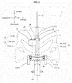
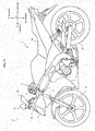
- Fig. 1 is a right side view of the straddled vehicle according to an embodiment.
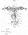
- Fig. 2 is a front view of a portion of the straddled vehicle according to the embodiment.
- Fig. 3 is a plan view of a front portion of the straddled vehicle according to the embodiment.
- Figs. 1 and 2 show a longitudinal direction X, a transverse direction Y, and an up-down direction Z of a straddled vehicle 1.
- the longitudinal direction X, transverse direction Y, and up-down direction Z are defined with reference to a rider mounted on the straddled vehicle 1.
- the longitudinal direction X, transverse direction Y, and up-down direction Z are perpendicular to one another.
- Figs. 2 and 3 show a vehicle center plane C.
- the vehicle center plane C is an imaginary plane extending through the center of the straddled vehicle 1 and perpendicular to the transverse direction Y.
- the straddled vehicle 1 is a scooter type vehicle.
- the straddled vehicle 1 has a body frame 3.
- Fig. 1 shows parts of the body frame 3 in broken lines.
- the body frame 3 includes a head tube 4 and a down frame 5.
- the head tube 4 is disposed at the front of the straddled vehicle 1.
- the head tube 4 is located on the vehicle center plane C (see Fig. 2 ).
- the down frame 5 is connected to the head tube 4.
- the down frame 5 extends downward and rearward from the head tube 4.
- the straddled vehicle 1 has a steering device 11 and a front wheel 21.
- the steering device 11 is pivotably supported by the head tube 4.
- the steering device 11 supports the front wheel 21.
- the direction of the front wheel 21 changes with pivoting of the steering device 11. This changes the course taken by the straddled vehicle 1.
- the steering device 11 has a steering shaft 12, a handlebar 13, a bracket 14, a pair of suspensions 15, and an axle 16.
- the steering shaft 12 is mounted in the head tube 4.
- the head tube 4 rotatably supports the steering shaft 12.
- the handlebar 13 extends in the transverse direction Y.
- the handlebar 13 is connected to the steering shaft 12 in a position higher than the head tube 4.
- the steering shaft 12 extends downward from the handlebar 13 through the head tube 4.
- the bracket 14 is connected to the steering shaft 12 in a position lower than the head tube 4.
- Each suspension 15 is connected to the bracket 14.
- Each suspension 15 extends downward from the bracket 14 (see Fig. 2 ).
- the axle 16 is supported by the pair of suspensions 15.
- the axle 16 is connected to a lower part of each suspension 15.
- the axle 16 rotatably supports the front wheel 21.
- the straddled vehicle 1 has a right brake lever 18.
- the right brake lever 18 is attached to the handlebar 13.
- the handlebar 13 has a right grip portion 13R.
- the right grip portion 13R is located at a right end of the handlebar 13.
- the right brake lever 18 is disposed adjacent the right grip portion 13R.
- the right brake lever 18 is a brake operating element.
- the straddled vehicle 1 has a master cylinder 19.
- the master cylinder 19 generates hydraulic pressure of a brake fluid in response to operation of the right brake lever 18.
- the master cylinder 19 is fixed to the handlebar 13.
- the master cylinder 19 is disposed adjacent the right grip portion 13R.
- the master cylinder 19 is also disposed adjacent the right brake lever 18.
- the straddled vehicle 1 has a front wheel brake 23.
- the front wheel brake 23 is operable by the hydraulic pressure of the brake fluid.
- the front wheel brake 23 brakes the front wheel 21.
- the front wheel brake 23 has a brake disk 24 and a caliper 25.
- the brake disk 24 is fixed to the front wheel 21.
- the brake disk 24 is rotatable with the front wheel 21.
- the caliper 25 is supported by the steering device 11.
- the caliper 25 is supported by one of the suspensions 15, for example.
- the caliper 25 brakes rotation of the brake disk 24 with the hydraulic pressure of the brake fluid.
- the caliper 25 has brake pads (not shown) for contacting both sides of the brake disk 24. The brake pads are pressed on both sides of the brake disk 24 by the hydraulic pressure of the brake fluid. This brakes rotation of the brake disk 24.
- the front wheel brake 23 is an example of the hydraulic brake according to the present teaching.
- the straddled vehicle 1 has a hydraulic unit 27.
- the hydraulic unit 27 receives input of the hydraulic pressure generated by the master cylinder 19.
- the hydraulic unit 27 regulates the hydraulic pressure for braking to prevent lock tendency of the front wheel 21.
- the hydraulic unit 27 outputs a regulated hydraulic pressure to the front wheel brake 23 (caliper 25).
- the number of channels provided for the hydraulic unit 27 is one. That is, the hydraulic unit 27 controls only one brake system (specifically, the brake system for the front wheel 21). Specifically, the number of master cylinders connected to the hydraulic unit 27 is one (master cylinder 19). In other words, the number of master cylinders which input the hydraulic pressure of the brake fluid to the hydraulic unit 27 is one. The number of brakes connected to the hydraulic unit 27 is one (front wheel brake 23). In other words, the number of brakes to which the hydraulic unit 27 outputs the hydraulic pressure of the brake fluid is one.
- the hydraulic unit 27 is fixed to the head tube 4.
- the hydraulic unit 27 is located forward of the head tube 4.
- the hydraulic unit 27 does not overlap the head tube 4 in the side view of the vehicle (see Fig. 1 ).
- the hydraulic unit 27 is located lower than the master cylinder 19.
- the hydraulic unit 27 is located higher than the front wheel brake 23.
- the hydraulic unit 27 is located within a range in the up-down direction Z in which the head tube 4 is located. Specifically, the hydraulic unit 27 is located in a position lower than a top end 4t of the head tube 4 and higher than a bottom end 4b of the head tube 4.
- the straddled vehicle 1 has appearance constituent members 31.
- Fig. 2 shows the appearance constituent members 31 in broken lines.
- Fig. 3 shows sections of the appearance constituent members 31 taken on line A-A of Fig. 1 .
- the appearance constituent members 31 are members which constitute an appearance of the straddled vehicle 1.
- the appearance constituent members 31 are arranged around the head tube 4.
- the appearance constituent members 31 are composed of a cover member 6 and members attached to the cover member 6.
- the appearance constituent members 31 include lamp units 33 in addition to the cover member 6.
- the cover member 6 includes a front cover 32 and leg shields 7.
- the front cover 32 extends leftward and rearward from a leading edge 32a thereof.
- the front cover 32 also extends rightward and rearward from the leading edge 32a.
- the front cover 32 has openings formed therein for exposing the lamp units 33.
- the leg shields 7 are arranged behind the head tube 4.
- the leg shields 7 are connected to the front cover 32 in positions rightward and leftward of the head tube 4.
- the lamp units 33 are attached to the front cover 32.
- the lamp units 33 have clear lenses exposed from the openings of the front cover 32.
- the lamp units 33 include headlights 34 and position lights 35.
- the headlights 34 include a right headlight 34R and a left headlight 34L (see Fig. 2 ).
- the position lights 35 include a right position light 35R and a left position light 35L (see Fig. 2 ).
- the appearance constituent members 31 overlap the head tube 4 in the front view of the vehicle (see Fig. 2 ).
- the appearance constituent members 31 cover areas in front of the head tube 4.
- the appearance constituent members 31 are arranged rightward and leftward of the head tube 4.
- the appearance constituent members 31 overlap the head tube 4 in the side view of the vehicle (see Fig. 1 ).
- the appearance constituent members 31 cover areas rightward and leftward of the head tube 4.
- the hydraulic unit 27 is disposed in the space between the head tube 4 and appearance constituent members 31. In other words, the hydraulic unit 27 is disposed inward of the appearance constituent members 31. This will be described particularly hereinafter.
- the appearance constituent members 31 are arranged in front of the hydraulic unit 27.
- the appearance constituent members 31 overlap the hydraulic unit 27 in the front view of the vehicle (see Fig. 2 ).
- the appearance constituent members 31 cover areas in front of the hydraulic unit 27.
- the appearance constituent members 31 are arranged rightward and leftward of the hydraulic unit 27.
- the appearance constituent members 31 overlap the hydraulic unit 27 in the side view of the vehicle (see Fig. 1 ).
- the appearance constituent members 31 cover areas rightward and leftward of the hydraulic unit 27.
- the straddled vehicle 1 has a seat 36.
- the seat 36 is disposed rearward of the head tube 4.
- the rider of the straddled vehicle 1 sits on the seat 36, grasps the handlebar 13 (e.g. the right grip portion 13R), and operates the right brake lever 18.
- the straddled vehicle 1 has a drive unit 37, a rear wheel 38, and a rear suspension 39.
- the drive unit 37 includes an engine for generating power, and a transmission for transmitting the power of the engine to the rear wheel 38.
- the drive unit 37 is disposed below the seat 36.
- the drive unit 37 has a front part thereof swingably supported by the body frame 3.
- the drive unit 37 has a rear part supporting the rear wheel 38.
- the drive unit 37 drives and rotates the rear wheel 38.
- the rear suspension 39 supports the rear part of the drive unit 37.
- One end of the rear suspension 39 is supported by the body frame 3.
- the other end of the rear suspension 39 is attached to the rear part of the drive unit 37.
- the center yc1 of the hydraulic unit 27 in the transverse direction Y is located rightward of the vehicle center plane C. That is, the center yc1 is not located on the vehicle center plane C, but is shifted from the vehicle center plane C. Consequently, a relatively large space S can be formed leftward of the hydraulic unit 27.
- the hydraulic unit 27 is disposed in a position displaced from the vehicle center plane C. Specifically, the entire hydraulic unit 27 is located rightward of the vehicle center plane C. This can further enlarge the space S.
- the hydraulic unit 27 overlaps the head tube 4 in the front view of the vehicle.
- the hydraulic unit 27 overlaps the head tube 4 in the plan view (see Fig. 3 ). Consequently, the hydraulic unit 27 can conveniently be fixed to the head tube 4.
- the hydraulic unit 27 has a first connector 28 and a second connector 29.
- the first connector 28 and second connector 29 are arranged on the same surface of the hydraulic unit 27.
- the first connector 28 and second connector 29 are both arranged on an upper surface of the hydraulic unit 27.
- the first connector 28 and second connector 29 are arranged in the same height position.
- the second connector 29 is disposed rightward of the first connector 28. In other words, the position of the second connector 29 in the transverse direction Y is located rightward of the position of the first connector 28 in the transverse direction Y.
- the first connector 28 is located on the same side of the vehicle center plane C as the second connector 29. Specifically, the first connector 28 and second connector 29 are both arranged rightward of the vehicle center plane C.
- the first connector 28 overlaps the head tube 4 in the front view of the vehicle.
- the second connector 29 does not overlap the head tube 4 in the front view of the vehicle.
- the first connector 28 and second connector 29 are arranged in a line along the transverse direction Y.
- the second connector 29 is located in the same position in the longitudinal direction X as the first connector 28. In other words, the position of the second connector 29 in the longitudinal direction X is the same as the position of the first connector 28 in the longitudinal direction X.
- the second connector 29 is located between the front end and rear end of the first connector 28.
- the straddled vehicle 1 has first piping 41.
- the first piping 41 transmits the hydraulic pressure of the brake fluid.
- the first piping 41 is connected to the first connector 28.
- the first piping 41 has a first end 42 connected to the first connector 28.
- the straddled vehicle 1 has second piping 51.
- the second piping 51 transmits the hydraulic pressure of the brake fluid.
- the second piping 51 is connected to the second connector 29.
- the second piping 51 has a second end 52 connected to the second connector 29.
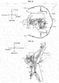
- Fig. 4 is a right side view of the front portion of the straddled vehicle 1.
- Fig. 5 is a front view of a portion of the straddled vehicle 1.
- Fig. 6 is a left side view of a portion of the straddled vehicle 1.
- Figs. 4-6 omit illustration of the appearance constituent members 31.
- the first piping 41 is further connected to the front wheel brake 23 (caliper 25).
- the first piping 41 transmits the hydraulic pressure of the brake fluid from the hydraulic unit 27 to the front wheel brake 23 (caliper 25).
- the first piping 41 has a first proximal pipe 44, a first joint member 45, and a first distal pipe 46.
- the first proximal pipe 44, first joint member 45, and first distal pipe 46 are connected in this order.
- the first proximal pipe 44 includes the first end 42. One end of the first proximal pipe 44 is the first end 42. The one end of the first proximal pipe 44 is connected to the first connector 28. The other end of the first proximal pipe 44 is connected to the first joint member 45.
- the first joint member 45 is a straight type.
- the first joint member 45 has a short, approximately straight pipe shape.
- One end of the first joint member 45 is connected to the first proximal pipe 44.
- the other end of the first joint member 45 is connected to the first distal pipe 46.
- the first distal pipe 46 has one end connected to the first joint member 45.
- the first distal pipe 46 has the other end connected to the front wheel brake 23 (caliper 25) (see Fig. 4 ).
- the second piping 51 is further connected to the master cylinder 19.
- the second piping 51 transmits the hydraulic pressure of the brake fluid from the master cylinder 19 to the hydraulic unit 27.
- the second piping 51 has a second proximal pipe 54, a second joint member 55, and a second distal pipe 56.
- the second proximal pipe 54, second joint member 55, and second distal pipe 56 are connected in this order.
- the second proximal pipe 54 includes the second end 52. One end of the second proximal pipe 54 is the second end 52. The one end of the second proximal pipe 54 is connected to the second connector 29. The other end of the second proximal pipe 54 is connected to the second joint member 55.
- the second joint member 55 is a straight type.
- the second joint member 55 has a short, approximately straight pipe shape.
- One end of the second joint member 55 is connected to the second proximal pipe 54.
- the other end of the second joint member 55 is connected to the second distal pipe 56.
- the second distal pipe 56 has one end connected to the second joint member 55.
- the second distal pipe 56 has the other end connected to the master cylinder 19 (see Fig. 5 ).
- the first proximal pipe 44 and second proximal pipe 54 do not have flexibility, respectively.
- the first proximal pipe 44 and second proximal pipe 54 are steel pipes, respectively, for example.
- the first proximal pipe 44 and second proximal pipe 54 are formed of metal, respectively, for example.
- the first distal pipe 46 and second distal pipe 56 have flexibility, respectively.
- the first distal pipe 46 and second distal pipe 56 are rubber pipes, respectively, for example. When rubber pipes are employed, the rubber pipes have a larger diameter than the steel pipes.
- the first proximal pipe 44, first joint member 45, second proximal pipe 54, and second joint member 55 are arranged in the space between the head tube 4 and appearance constituent members 31. Although not shown, these elements 44, 45, 54 and 55 overlap the appearance constituent members 31 in the front view and side view of the vehicle.
- Part of the first distal pipe 46 (including the one end of the first distal pipe 46) and part of the second distal pipe 56 (including the one end of the second distal pipe 56) are arranged between the head tube 4 and appearance constituent members 31.
- the part of the first distal pipe 46 and the part of the second distal pipe 56 overlap the appearance constituent members 31 in the front view and side view of the vehicle.
- the first piping 41 and second piping 51 are arranged, respectively, out of contact with the appearance constituent members 31,
- the first piping 41 and second piping 51 are arranged out of contact with each other.
- the first end 42 and second end 52 will be described first.
- the first end 42 and second end 52 extend in mutually different directions. Specifically, the first end 42 extends rightward and rearward from the first connector 28, while the second end 52 extends leftward and forward from the second connector 29. The first end 42 and second end 52 extend in mutually opposite directions.
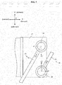
- Fig. 7 is a plan view of the hydraulic unit 27, first end 42, and second end 52.
- the first end 42 and second end 52 have a linear shape, respectively.
- the first end 42 extends in a first direction D1 from the first connector 28.
- the second end 52 extends in a second direction D2 from the second connector 29.
- the first direction D1 includes a component u1 in the longitudinal direction X, and a component v1 in the transverse direction Y.
- the second direction D2 includes a component u2 in the longitudinal direction X, and a component v2 in the transverse direction Y.
- “the first direction D1 includes a component u1” means that the component u1 is not zero. The same applies to the other components v1, u2 and v2.
- the components u1 and u2 have mutually opposite directions.
- the component u1 points rearward while the component u2 points forward.
- the components v1 and v2 have mutually opposite directions.
- the component v1 points rightward while the component v2 points leftward.
- the first direction D1 and second direction D2 have a large difference. Specifically, in the plan view, the difference between the first direction D1 and second direction D2 is larger than 90 degrees.
- the first piping 41 extends upward from the first end 42, and thereafter changes the direction to extend downward. That is, the first piping 41 has an upwardly curved portion 43 which is curved to form an upward protuberance.
- the upwardly curved portion 43 is curved to bulge upward.
- the upwardly curved portion 43 has a substantially arcuate shape.
- the upwardly curved portion 43 is formed on the first proximal pipe 44. That is, the first proximal pipe 44 includes the upwardly curved portion 43.
- the upwardly curved portion 43 is located in a position higher than any one of the first connector 28 and second connector 29.
- the upwardly curved portion 43 is located in a position higher than the hydraulic unit 27.
- the first piping 41 extends upward from the first end 42 toward the upwardly curved portion 43, the first piping 41 also extends leftward and rearward (see Fig. 3 ).
- the upwardly curved portion 43 is located rearward of the hydraulic unit 27 and forward of the head tube 4.
- the upwardly curved portion 43 is located leftward of any one of the first connector 28 and second connector 29.
- the upwardly curved portion 43 is located leftward of the hydraulic unit 27.
- the first piping 41 extends downward from the upwardly curved portion 43 to a position lower than the hydraulic unit 27.
- the first piping 41 passes through an area on the left side of the hydraulic unit 27.
- the portion of the first piping 41 passing through the area leftward of the hydraulic unit 27 extends substantially in the up-down direction Z between a position higher than the hydraulic unit 27 and a position lower than the hydraulic unit 27.
- the portion of the first piping 41 passing through the area leftward of the hydraulic unit 27 is located forward of the head tube 4.
- the first joint member 45 is located in substantially the same height position as an upper end of the hydraulic unit 27.
- the first joint member 45 is located rearward of the hydraulic unit 27.
- the first joint member 45 is located forward of the head tube 4.
- the first joint member 45 is placed in a substantially vertical posture. In other words, the first joint member 45 is placed in such a way that an imaginary line extending between one end and the other end of the first joint member 45 runs substantially parallel to the up-down direction Z.
- the first distal pipe 46 extends downward from the first joint member 45.
- the first joint member 45 is located leftward and rearward of the hydraulic unit 27.
- the first joint member 45 overlaps the head tube 4 in the plan view.
- the first piping 41 extends further downward and reaches the front wheel brake 23 (caliper 25).
- the second piping 51 extends leftward from the second end 52 to a position leftward of the hydraulic unit 27 (see Figs. 3 and 5 ).
- the second piping 51 then extends downward through an area leftward of the hydraulic unit 27, and thereafter changes the direction to extend upward (see Figs. 5 and 6 ). That is, the second piping 51 has a downwardly curved portion 53 which is curved to form a downward protuberance.
- the downwardly curved portion 53 is curved to bulge downward.
- the downwardly curved portion 53 has a substantially arcuate shape.
- the downwardly curved portion 53 is formed on the second proximal pipe 54. That is, the second proximal pipe 54 includes the downwardly curved portion 53.
- the downwardly curved portion 53 is located in a position lower than any one of the first connector 28 and second connector 29.
- the downwardly curved portion 53 is located in substantially the same height position as a lower end of the hydraulic unit 27.
- the downwardly curved portion 53 is located leftward of any one of the first connector 28 and second connector 29.
- the downwardly curved portion 53 is located leftward of the hydraulic unit 27.
- the downwardly curved portion 53 overlaps the hydraulic unit 27 in the side view of the vehicle.
- the downwardly curved portion 53 is located forward of the head tube 4.
- the downwardly curved portion 53 is located forward of the portion of the first piping 41 passing through the area leftward of the hydraulic unit 27.
- the second piping 51 extends upward from the downwardly curved portion 53 to a position higher than the hydraulic unit 27.
- the second piping 51 passes through an area leftward of the hydraulic unit 27.
- the portion of the second piping 51 passing through the area leftward of the hydraulic unit 27 extends substantially in the up-down direction Z between a position higher than the hydraulic unit 27 and a position lower than the hydraulic unit 27.
- the portion of the second piping 51 passing through the area leftward of the hydraulic unit 27 is located forward of the head tube 4.
- the portion of the second piping 51 passing through the area leftward of the hydraulic unit 27 is located forward of the portion of the first piping 41 passing through the area leftward of the hydraulic unit 27. That is, the portion of the first piping 41 passing through the area leftward of the hydraulic unit 27 and the portion of the second piping 51 passing through the area leftward of the hydraulic unit 27 are arranged in a line along the longitudinal direction X in the side view of the vehicle.
- the second proximal pipe 54 is switched to the second distal pipe 56 by the second joint member 55.
- the second joint member 55 is located in substantially the same height position as the upper end of the hydraulic unit 27.
- the second joint member 55 overlaps the hydraulic unit 27 in the side view of the vehicle.
- the second joint member 55 is located rearward of any one of the first connector 28 and second connector 29.
- the second joint member 55 is located forward of the head tube 4.
- the second joint member 55 is placed in a substantially vertical posture.
- the second distal pipe 56 extends upward from the second joint member 55.
- the second joint member 55 is located leftward of the hydraulic unit 27.
- the second joint member 55 overlaps the head tube 4 in the plan view.
- the second joint member 55 is located forward of the first joint member 45.
- the second piping 51 extends further upward.
- the second piping 51 reaches a height position substantially corresponding to the handlebar 13
- the second piping 51 extends rightward and reaches the master cylinder 19.
- the master cylinder 19 is located rightward of the vehicle center plane C.
- the first proximal pipe 44 and second proximal pipe 54 will be described.
- first proximal pipe 44 and second proximal pipe 54 do not overlap. In other words, in the plan view, the first proximal pipe 44 and second proximal pipe 54 do not cross.
- Fig. 8 is a plan view of the hydraulic unit 27, first piping 41, and second piping 51.
- Fig. 8 shows a range W1 in the transverse direction Y in which the first proximal pipe 44 is located.
- the first proximal pipe 44 is disposed within the range W1 in the transverse direction Y.
- the range W1 deviates rightward of the vehicle center plane C. That is, the range W1 has a midpoint thereof located rightward of the vehicle center plane C. In this embodiment, almost the whole of the range W1 is located rightward of the vehicle center plane C.
- Fig. 8 shows a range W2 in the transverse direction Y in which the second proximal pipe 54 is located.
- the second proximal pipe 54 is disposed in the range W2 in the transverse direction Y.
- the range W2 deviates rightward of the vehicle center plane C. That is, the range W2 has a midpoint thereof located rightward of the vehicle center plane C.
- Fig. 8 shows a right end PR of an entirety of the hydraulic unit 27, first joint member 45, and second joint member 55.
- Fig. 8 shows a left end PL of the entirety of the hydraulic unit 27, first joint member 45, and second joint member 55.
- the first joint member 45 is located leftward of the hydraulic unit 27, and the second joint member 55 is located leftward of the first joint member 45.
- the right end PR therefore corresponds to a right end of the hydraulic unit 27.
- the left end PL corresponds to a left end of the second joint member 55.
- the first proximal pipe 44 and second proximal pipe 54 are arranged leftward of the right end PR, respectively. That is, the first proximal pipe 44 and second proximal pipe 54 do not protrude rightward of the hydraulic unit 27, respectively. Further, the first proximal pipe 44 and second proximal pipe 54 are arranged rightward of the left end PL, respectively.
- Fig. 8 shows a range W3 in the transverse direction Y in which the hydraulic unit 27, first joint member 45, and second joint member 55 are located.
- the hydraulic unit 27, first joint member 45, and second joint member 55 are arranged within the range W3 in the transverse direction Y.
- the range W1 and range W2 are included in the range W3. That is, the first proximal pipe 44 and second proximal pipe 54 are arranged within the range W3 in the transverse direction Y.
- the straddled vehicle 1 includes a stay 61 for supporting the hydraulic unit 27.
- the stay 61 is fixed to the head tube 4.
- the stay 61 extends forward from the head tube 4.
- the stay 61 is connected to a left surface of the hydraulic unit 27 by a fastening member 62.
- the stay 61 is connected to a lower surface of the hydraulic unit 27 by a fastening member 63.
- the stay 61 provides a cantilever support for the hydraulic unit 27. Consequently, the stay 61 can conveniently support the hydraulic unit 27 having the center yc1 thereof located rightward of the vehicle center plane C.
- the straddled vehicle 1 includes a first holding member 65 for holding the first piping 41.
- the first holding member 65 holds the first distal pipe 46.
- the first holding member 65 holds the end of the first distal pipe 46 connected to the first joint member 45.
- the first holding member 65 has an annular shape, and contacts an outer circumferential surface of the first piping 41.
- the first holding member 65 is connected to the stay 61 by a fastening member 66. Consequently, the first holding member 65 holds the first piping 41 in a predetermined position. That is, the first holding member 65 positions the first piping 41.
- the straddled vehicle 1 includes a second holding member 67 for holding the second piping 51.
- the second holding member 67 holds the second distal pipe 56.
- the second holding member 67 holds the end of the second distal pipe 56 connected to the second joint member 55.
- the second holding member 67 has an annular shape, and contacts an outer circumferential surface of the second piping 51.
- the second holding member 67 is connected to the stay 61 by a fastening member 68. Consequently, the second holding member 67 holds the second piping 51 in a predetermined position. That is, the second holding member 67 positions the second piping 51.
- the first holding member 65 and second holding member 67 are close to each other.
- the first holding member 65 and second holding member 67 are respectively arranged within the range in the up-down direction Z in which the head tube 4 is located.
- the first holding member 65 is disposed in a position lower than the top end 4t of the head tube 4 and higher than the bottom end 4b of the head tube 4.
- the second holding member 67 is disposed in a position lower than the top end 4t of the head tube 4 and higher than the bottom end 4b of the head tube 4.
- the first holding member 65 and second holding member 67 are arranged in a line in the up-down direction Z.
- the second holding member 67 is disposed above the first holding member 65.
- the smaller distance from the head tube 4 (more particularly a central axis of the head tube 4 or an axis of rotation of the steering device 11) to the first holding member 65 results in the smaller variation length of the first piping 41.
- the smaller distance from the head tube 4 to the second holding member 67 results in the smaller variation length of the second piping 51.
- the first holding member 65 and second holding member 67 are arranged in positions closer to the head tube 4 than to the right end PR of the hydraulic unit 27.
- the right end PR of the hydraulic unit 27 corresponds to one end of the hydraulic unit 27 farthest from the head tube 4. This provides the short variation lengths of the first piping 41 and second piping 51 caused by the pivoting of the steering device 11. Therefore, even when the steering device 11 pivots relative to the head tube 4, the first piping 41 and second piping 51 do not easily interfere with each other.
- the straddled vehicle 1 according to the embodiment produces the following effects.
- the relatively large space S can be formed leftward of the hydraulic unit 27.
- the space S can easily accommodate components ("other components") other than the hydraulic unit 27.
- the hydraulic unit 27 can be placed efficiently in the space between the head tube 4 and appearance constituent members 31.
- Fig. 9 is a front view of a portion of the straddled vehicle 1.
- Fig. 10 is a plan view of the front portion of the straddled vehicle.
- Fig. 11 is a left side view of the front portion of the straddled vehicle.
- Fig. 9 shows the appearance constituent members 31 in a dotted line.
- Fig. 10 shows sections of the appearance constituent members 31 taken on line A-A of Fig. 1 .
- Fig. 11 omits illustration of the appearance constituent members 31.
- the straddled vehicle 1 includes a storage unit 71 for storing accessories and other articles.
- the storage unit 71 is disposed in the space between the head tube 4 and appearance constituent members 31.
- the appearance constituent members 31 are located forward of the storage unit 71.
- the appearance constituent members 31 overlap the storage unit 71 in the front view of the vehicle (see Fig. 9 ).
- the appearance constituent members 31 cover an area in front of the storage unit 71.
- the appearance constituent members 31 are located rightward and leftward of the storage unit 71.
- the appearance constituent members 31 overlap the storage unit 71 in side views of the vehicle.
- the appearance constituent members 31 cover areas rightward and leftward of the storage unit 71.
- the storage unit 71 has a center yc2 thereof in the transverse direction Y, which is located leftward of the vehicle center plane C.
- the center yc2 is located in the opposite side to the center yc1 across the vehicle center plane C. Consequently, the hydraulic unit 27 and storage unit 71 can be arranged conveniently.
- the storage unit 71 is a relatively large member.
- the storage unit 71 is relatively long in the longitudinal direction X.
- the storage unit 71 has a portion located forward of the head tube 4 and a portion located rearward of the head tube 4 (see Figs. 10 and 11 ).
- the storage unit 71 can be positioned conveniently. In other words, the storage unit 71 can easily be increased in size.
- the center yc1 of the hydraulic unit 27 in the transverse direction Y is located rightward of the vehicle center plane C.
- the appearance constituent members 31 are therefore located close to the right side of the hydraulic unit 27.
- the first piping 41 and second piping 51 are installed in positions closer to the right parts of the appearance constituent members 31 than to the left parts of the appearance constituent members 31.
- the first connector 28 is located leftward of the second connector 29. The first connector 28 is therefore farther than the second connector 29 from the right parts of the appearance constituent members 31.
- the first end 42 extends in the first direction D1 from the first connector 28.
- the component v1 in the transverse direction Y of the first direction D1 points rightward.
- the first end 42 extends rightward from the first connector 28.
- the first end 42 extends in a direction toward the right parts of the appearance constituent members 31. Since the first connector 28 is farther than the second connector 29 from the right parts of the appearance constituent members 31 even if the first end 42 extends rightward from the first connector 28, the first piping 41 can be arranged appropriately. For example, the radius of curvature of the first piping 41 can easily be enlarged. For example, the first piping 41 can easily be extended in the transverse direction Y. For example, the first piping 41 can easily be extended in the up-down direction Z and longitudinal direction X also. Thus, the first piping 41 can be arranged appropriately, while conveniently avoiding the first piping 41 contacting the right parts of the appearance constituent members 31.
- the second connector 29 is located rightward of the first connector 28.
- the second connector 29 is therefore closer than the first connector 28 to the right parts of the appearance constituent members 31.
- the second end 52 extends in the second direction D2 from the second connector 29.
- the component v2 in the transverse direction Y of the second direction D2 points leftward.
- the second end 52 extends leftward from the second connector 29. That is, the second end 52 extends in a direction away from the right parts of the appearance constituent members 31.
- the second piping 51 can be arranged appropriately. For example, the radius of curvature of the second piping 51 can easily be enlarged.
- the second piping 51 can easily be extended in the transverse direction Y.
- the second piping 51 can easily be extended in the up-down direction Z and longitudinal direction X also.
- the second piping 51 can be arranged appropriately, while conveniently avoiding the second piping 51 contacting the appearance constituent members 31.
- the first end 42 extends rightward, and the second end 52 leftward.
- the first piping 41 and second piping 51 can be arranged appropriately without contacting the appearance constituent members 31.
- first end 42 and second end 52 do not extend in the same direction.
- the first end 42 and second end 52 can therefore be conveniently inhibited from contacting each other,
- the first piping 41 and second piping 51 can be arranged appropriately. This also facilitates operation to install the first piping 41 and second piping 51.
- first end 42 is connected to the first connector 28, the position of the first end 42 can be set easily.
- second end 52 is connected to the second connector 29, the position of the second end 52 can be set easily.
- the first piping 41 and second piping 51 can therefore be inhibited from contacting each other all the more conveniently.
- the component u1 in the longitudinal direction X of the first direction D1 points opposite to the component u2 in the longitudinal direction X of the second direction D2. Consequently, the first direction D1 and second direction D2 have a large difference.
- the first piping 41 and second piping 51 can therefore be inhibited from contacting each other all the more conveniently.
- the first connector 28 and second connector 29 are arranged on the same surface (specifically, the upper surface) of the hydraulic unit 27.
- the first end 42 and second end 52 are therefore all the closer to each other. Since the first end 42 and second end 52 are appropriately arranged, even if the first end 42 and second end 52 are close to each other, the first end 42 and second end 52 can conveniently be inhibited from mutual interference.
- the first piping 41 and second piping 51 can therefore be arranged all the more appropriately.
- Both the first connector 28 and second connector 29 are located on one side of the vehicle center plane C. Therefore, the portion (e.g. the first proximal pipe 44) of the first piping 41 located adjacent the hydraulic unit 27 can easily be installed on one side of the vehicle center plane C. Similarly, the portion (e.g. the second proximal pipe 54) of the second piping 51 located adjacent the hydraulic unit 27 can easily be installed on one side of the vehicle center plane C. Thus, the portion of the first piping 41 and the portion of the second piping 51 adjacent the hydraulic unit 27 can easily be shifted to one side of the vehicle center plane C. Or the portion of the first piping 41 and the portion of the second piping 51 adjacent the hydraulic unit 27 can be installed together on one side of the vehicle center plane C.
- each of the range W1 in the transverse direction Y in which the first proximal pipe 44 is located and the range W2 in the transverse direction Y in which the second proximal pipe 54 is located can easily be made to deviate to one side of the vehicle center plane C. Consequently, the portion of the first piping 41 and the portion of the second piping 51 adjacent the hydraulic unit 27 can be arranged efficiently in the space between the head tube 4 and appearance constituent members 31.
- first connector 28 and second connector 29 are both located on the same side of the vehicle center plane C as the center yc1.
- the hydraulic unit 27, and the portion of the first piping 41 and the portion of the second piping 51 adjacent the hydraulic unit 27, can therefore be arranged efficiently.
- the space S leftward of the hydraulic unit 27 can conveniently be inhibited from being reduced in size by the portion of the first piping 41 and the portion of the second piping 51 adjacent the hydraulic unit 27.
- the first proximal pipe 44 and second proximal pipe 54 are arranged leftward of the right end PR of the entirety of the hydraulic unit 27, first joint member 45, and second joint member 55, and are arranged rightward of the left end PL of the entirety of the hydraulic unit 27, first joint member 45, and second joint member 55. Further, each of the first joint member 45 and second joint member 55 overlaps the head tube 4 in the plan view.
- the hydraulic unit 27, first proximal pipe 44, second proximal pipe 54, first joint member 45, and second joint member 55 can therefore be arranged efficiently. As a result, the space S leftward of the hydraulic unit 27 can conveniently be inhibited from being reduced in size by the first proximal pipe 44, second proximal pipe 54, first joint member 45, and second joint member 55.
- first proximal pipe 44, second proximal pipe 54, first joint member 45, and second joint member 55 can therefore be arranged all the more efficiently.
- the portion of the first piping 41 and the portion of the second piping 51 passing through the area leftward of the hydraulic unit 27 are arranged in a line along the longitudinal direction X in the side view of the vehicle. Consequently, the portion of the first piping 41 and the portion of the second piping 51 adjacent the hydraulic unit 27 can be arranged all the more efficiently.
- the first joint member 45 and second joint member 55 are arranged in a line along the longitudinal direction X leftward of the hydraulic unit 27. Consequently, the portion of the first piping 41 and the portion of the second piping 51 adjacent the hydraulic unit 27 can be arranged all the more efficiently.
- the first proximal pipe 44 and second proximal pipe 54 do not overlap in the plan view. This can reliably prevent the first proximal pipe 44 and second proximal pipe 54 from contacting each other.
- the first proximal pipe 44 and second proximal pipe 54 do not have flexibility, respectively. This can prevent with increased reliability the first proximal pipe 44 and second proximal pipe 54 from contacting each other.
- the first piping 41 has the upwardly curved portion 43 which is located in the position higher than any one of the first connector 28 and second connector 29. This can further increase the length of the first piping 41 (specifically, the first distal pipe 46). The first piping 41 can therefore conveniently bend with pivoting of the front wheel brake 23.
- the first distal pipe 46 has flexibility. The first distal pipe 46 can therefore conveniently bend with pivoting of the front wheel brake 23.
- the second piping 51 has the downwardly curved portion 53 which is located in the position lower than any one of the first connector 28 and second connector 29. This can further increase the length of the second piping 51 (specifically, the second distal pipe 56).
- the second piping 41 can therefore conveniently bend with pivoting of the master cylinder 19.
- the second distal pipe 56 has flexibility.
- the second distal pipe 56 can therefore conveniently bend with pivoting of the master cylinder 19.
- the number of master cylinders connected to the hydraulic unit 27 is one (master cylinder 19), and the number of brakes connected to the hydraulic unit 27 is one (front wheel brake 23).
- the number of pipes connected to the hydraulic unit 27 can therefore be kept down. Specifically, the pipes connected to the hydraulic unit 27 are only the first piping 41 and second piping 51. This can further reduce in size the installation space of the piping connected to the hydraulic unit 27.
- the first holding member 65 and second holding member 67 are located close to each other. This enables operations for detaching and attaching the first holding member 65 and operations for detaching and attaching the second holding member 67 to be performed without changing working posture.
Landscapes
- Engineering & Computer Science (AREA)
- Mechanical Engineering (AREA)
- Physics & Mathematics (AREA)
- Electromagnetism (AREA)
- Transportation (AREA)
- Fluid Mechanics (AREA)
- Valves And Accessory Devices For Braking Systems (AREA)
- Automatic Cycles, And Cycles In General (AREA)
- Regulating Braking Force (AREA)
- Motorcycle And Bicycle Frame (AREA)
Abstract
Description
- This invention relates to a straddled vehicle having a hydraulic device.
- Japanese Unexamined Patent Publication No.
2013-47018 - The hydraulic unit regulates the hydraulic pressure of a front brake, and the hydraulic pressure of a rear brake. The hydraulic unit is connected to four pipes. The four pipes are a front upstream pipe, a front downstream pipe, a rear upstream pipe, and a rear downstream pipe. The front upstream pipe connects a front master brake and the hydraulic unit. The front downstream pipe connects the hydraulic unit and the front brake. The rear upstream pipe connects a rear master cylinder and the hydraulic unit. The rear downstream pipe connects the hydraulic unit and the rear brake.
- The front upstream pipe and rear upstream pipe both extend in the same direction (e.g. forward) from the hydraulic unit. The front downstream pipe and rear downstream pipe both extend in the same direction (e.g. upward) from the hydraulic unit. The front upstream pipe and front downstream pipe are arranged to protrude to a large extent leftward of the hydraulic unit.
- However, the conventional example with such construction has the following problem.
- The head tube and front cover have only a narrow space in between. When headlights and the like are attached to the front cover, the space between the head tube and the front cover, headlights and the like is narrow. The front cover and the members (e.g. the headlights and the like) attached to the front cover are hereinafter collectively called "appearance constituent members". The hydraulic unit is installed in the space between the head tube and appearance constituent members. The hydraulic unit needs a relatively large installation space. Further, the components ("other components" hereinafter) other than the hydraulic unit are also installed in the space between the head tube and appearance constituent members. It is therefore difficult to arrange the hydraulic unit and other components appropriately between the head tube and appearance constituent members.
- It has been considered to place the hydraulic unit to have the center thereof in a transverse direction of the straddled vehicle located on a vehicle center plane. Here, the vehicle center plane is an imaginary plane which passes through the center of the straddled vehicle, and extends perpendicular to the transverse direction of the straddled vehicle. This arrangement can form one space rightward of the hydraulic unit and another space leftward of the hydraulic unit. These two spaces are divided by the hydraulic unit. Since the center of the hydraulic unit in the transverse direction is located on the vehicle center plane, the two spaces have substantially the same size. Thus, the narrow space between the head tube and appearance constituent members is divided substantially evenly into two spaces. Each of the two spaces is therefore relatively small. As a result, it may be difficult to arrange the other components in each space.
- Then, it has been considered to place the hydraulic unit in a position shifted from the vehicle center plane. Specifically, research was made to place the hydraulic unit to have the center thereof in the transverse direction located on one side of the vehicle center plane. This arrangement can form a relatively large space on either one of rightward and leftward of the hydraulic unit. The hydraulic unit and other components can therefore be arranged efficiently.
- However, it has been found that a new problem arises when the hydraulic unit is placed in the position shifted from the vehicle center plane. The new problem lies in a difficulty in appropriately installing the pipes connected to the hydraulic unit. With the relatively large space formed on either one of rightward and leftward of the hydraulic unit, the space formed on the other of rightward and leftward of the hydraulic unit is relatively small. That is, the appearance constituent members are located close to the other of the right and left sides of the hydraulic unit. This imposes limitations on locations where the pipes are installed. It is difficult to install the pipes appropriately in limited locations. It is difficult, for example, to install the pipes in locations out of contact with the appearance constituent members. It is difficult, for example, to install the pipes to be out of contact with one another.
- It is an object of the present invention to provide a straddled vehicle which can arrange a hydraulic unit efficiently in a space between a head tube and appearance constituent members.
- According to the present invention said object is solved by straddled vehicle having the features of
independent claim 1. Preferred embodiments are laid down in the dependent claims. - Accordingly it is provided the following construction.
- A straddled vehicle, comprises:
- a head tube;
- a steering device pivotably supported by the head tube;
- a hydraulic unit fixed to the head tube, and including a first connector, and a second connector disposed in the same position as the first connector in a transverse direction of the straddled vehicle or in a position rightward of the first connector;
- first piping connected to the first connector;
- second piping connected to the second connector;
- a master cylinder disposed higher than the hydraulic unit, fixed to the steering device, and connected to one of the first piping and the second piping;
- a hydraulic brake disposed lower than the hydraulic unit, and connected to the other of the first piping and the second piping; and
- an appearance constituent member disposed in front of the hydraulic unit, and disposed rightward and leftward of the hydraulic unit;
wherein - the hydraulic unit has a center thereof in the transverse direction, the center being located in one of directions rightward and leftward of a vehicle center plane extending through a center of the straddled vehicle and perpendicular to the transverse direction;
- the first piping has a first end connected to the first connector, the first end extending in a first direction from the first connector;
- the first direction includes a component in the transverse direction;
- the component in the transverse direction of the first direction points rightward;
- the second piping has a second end connected to the second connector, the second end extending in a second direction from the second connector;
- the second direction includes a component in the transverse direction; and
- the component in the transverse direction of the second direction points leftward.
- The center of the hydraulic unit in the transverse direction of the straddled vehicle is located on one side of the vehicle center plane. That is, the center of the hydraulic unit in the transverse direction is not on the vehicle center plane, but is shifted from the vehicle center plane. Consequently, a relatively large space can be formed either rightward or leftward of the hydraulic unit. The space between the head tube and appearance constituent member can therefore easily accommodate, along with the hydraulic unit, components other than the hydraulic unit. Thus, the hydraulic unit can be placed efficiently in the space between the head tube and appearance constituent member.
- The hydraulic unit includes the first connector and second connector. The second connector may be disposed in the same position as the first connector in the transverse direction of the straddled vehicle. In other words, the position of the second connector in the transverse direction may be the same as the position of the first connector in the transverse direction. Or the second connector may be disposed in a position rightward of the first connector.
- The first piping is connected to the first connector. The second piping is connected to the second connector. The first piping is further connected to one of the master cylinder and hydraulic brake. When the first piping is connected to the master cylinder, the second piping is connected to the hydraulic brake. When the first piping is connected to the hydraulic brake, the second piping is connected to the master cylinder.
- The first piping has the first end connected to the first connector. The first end extends in the first direction from the first connector. The first direction includes a component in the transverse direction. In other words, the component in the transverse direction of the first direction is not zero. Similarly, the second piping has the second end connected to the second connector. The second end extends in the second direction from the second connector. The second direction includes a component in the transverse direction. Here, the component in the transverse direction of the first direction points rightward. The component in the transverse direction of the second direction points leftward. The first piping and second piping can therefore be arranged appropriately.
- Assume, for example, that the center of the hydraulic unit in the transverse direction is located leftward of the vehicle center plane, and that the first connector is disposed leftward of the second connector. In this case, the first connector is disposed closer than the second connector to the appearance constituent member. That is, the appearance constituent member is located close to the left side of the first connector. Even in this case, since the first end extends rightward from the first connector, the first piping can be prevented from contacting the appearance constituent member, and the radius of curvature of the first piping can be inhibited from becoming too small. Further, since the first end and second end extend in different directions, the first piping and second piping can conveniently be prevented from contacting each other.
- Assume, for example, that the center of the hydraulic unit in the transverse direction is located rightward of the vehicle center plane, and that the second connector is disposed rightward of the first connector. In this case, the second connector is disposed closer than the first connector to the appearance constituent member. That is, the appearance constituent member is located close to the right side of the second connector. Even in this case, since the second end extends leftward from the second connector, the second piping can be prevented from contacting the appearance constituent member, and the radius of curvature of the second piping can be inhibited from becoming too small. Further, since the first end and second end extend in different directions, the first piping and second piping can conveniently be prevented from contacting each other.
- In the above straddled vehicle, it is preferred that the first direction includes a component in a longitudinal direction of the straddled vehicle; the second direction includes a component in the longitudinal direction; and the component in the longitudinal direction of the first direction points opposite to the component in the longitudinal direction of the second direction. When, for example, the component in the longitudinal direction of the first direction points forward, the component in the longitudinal direction of the second direction points rearward. When, for example, the component in the longitudinal direction of the first direction points rearward, the component in the longitudinal direction of the second direction points forward. Consequently, the first direction differs greatly from the second direction. In plan view, for example, the difference between the first direction and second direction is larger than 90 degrees. The first piping and second piping can therefore be inhibited from contacting each other all the more appropriately. Thus, the first piping and second piping can be arranged all the more appropriately.
- In the above straddled vehicle, it is preferred that the first direction includes a component in an up-down direction of the straddled vehicle; the second direction includes a component in the up-down direction; and the component in the up-down direction of the first direction points opposite to the component in the up-down direction of the second direction. When, for example, the component in the up-down direction of the first direction points upward, the component in the up-down direction of the second direction points downward. When, for example, the component in the up-down direction of the first direction points downward, the component in the up-down direction of the second direction points upward. Consequently, the first direction differs greatly from the second direction. In a front view of the vehicle, for example, the difference between the first direction and second direction is larger than 90 degrees. The first piping and second piping can therefore be inhibited from contacting each other all the more appropriately. Thus, the first piping and second piping can be arranged all the more appropriately.
- In the above straddled vehicle, it is preferred that the first connector and the second connector are arranged on the same surface of the hydraulic unit. Consequently, the first piping and second piping can be arranged all the more appropriately.
- In the above straddled vehicle, it is preferred that the first connector and the second connector are both located in one of the directions rightward and leftward of the vehicle center plane. In other words, the first connector preferably is located on the same side of the vehicle center plane as the second connector. According to this, the first piping and second piping adjacent the hydraulic unit can easily be installed on one side of the vehicle center plane. The first piping and second piping adjacent the hydraulic unit can be arranged efficiently in the space between the head tube and appearance constituent member.
- In the above straddled vehicle, it is preferred that the first piping has a first proximal pipe including the first end; a first joint member connected to the first proximal pipe; and a first distal pipe connected to the first joint member; and the second piping has a second proximal pipe including the second end; a second joint member connected to the second proximal pipe; and a second distal pipe connected to the second joint member; and wherein the first proximal pipe and the second proximal pipe do not overlap in plan view. The first proximal pipe, first joint member, and first distal pipe are connected in this order. The first end corresponds to one end of the first proximal pipe. Similarly, the second proximal pipe, second joint member, and second distal pipe are connected in this order. The second end corresponds to one end of the second proximal pipe. That "the first proximal pipe and the second proximal pipe do not overlap in plan view." means the same as that the first proximal pipe and the second proximal pipe do not intersect in plan view. This can reliably prevent contact between the first proximal pipe and second proximal pipe. That is, the first proximal pipe and second proximal pipe can be arranged all the more appropriately.
- In the above straddled vehicle, it is preferred that the first joint member overlaps the head tube in plan view; the second joint member overlaps the head tube in plan view; and the first proximal pipe and the second proximal pipe are arranged leftward of a right end of an entirety of the hydraulic unit, the first joint member, and the second joint member, and rightward of a left end of the entirety of the hydraulic unit, the first joint member, and the second joint member. Since the first joint member overlaps the head tube in plan view, the first joint member is disposed adjacent the head tube. Since the second joint member overlaps the head tube in plan view, the second joint member is disposed adjacent the head tube. The first proximal pipe and second proximal pipe are arranged within a range in the transverse direction in which the hydraulic unit, first joint member, and second joint member are located. As a result of these, the hydraulic unit, first joint member, second joint member, first proximal pipe, and second proximal pipe can be arranged efficiently. The relatively large space formed either rightward or leftward of the hydraulic unit can conveniently be inhibited from being reduced in size by the first proximal pipe, second proximal pipe, first joint member, and second joint member.
- In the above straddled vehicle, it is preferred that the number of the master cylinder to which the hydraulic unit is connected is one; and the number of the hydraulic brake to which the hydraulic unit is connected is one. In other words, the number of channels provided for the hydraulic unit preferably is one. This can keep down the number of pipes connected to the hydraulic unit. For example, the pipes connected to the hydraulic unit are limited to only the first piping and second piping. This can further reduce in size the installation space of the piping connected to the hydraulic unit.
- In the above straddled vehicle, it is preferred that one of the first piping and the second piping connected to the master cylinder has a downwardly curved portion which is curved to form a downward protuberance; and the downwardly curved portion is located in a position lower than any one of the first connector and the second connector. For expediency here, one of the first piping and the second piping connected to the master cylinder is called "upper piping". Since the downwardly curved portion is located in a position lower than any one of the first connector and the second connector, it can further increase the length of the upper piping. The upper piping can therefore conveniently bend with pivoting of the steering device.
- In the above straddled vehicle, it is preferred that the other of the first piping and the second piping connected to the hydraulic brake has an upwardly curved portion which is curved to form an upward protuberance; and the upwardly curved portion is located in a position higher than any one of the first connector and the second connector. For expediency here, the other of the first piping and the second piping connected to the hydraulic brake is called "lower piping". Since the upwardly curved portion is located in a position higher than any one of the first connector and the second connector, it can further increase the length of the lower piping. The lower piping can therefore conveniently bend with pivoting of the hydraulic brake.
- Preferably, the above straddled vehicle further comprises a storage unit disposed to overlap the hydraulic unit in a side view of the vehicle; wherein the storage unit has a center thereof in the transverse direction, which center is located opposite, across the vehicle center plane, to the center of the hydraulic unit in the transverse direction. When, for example, the center of the hydraulic unit in the transverse direction is located rightward of the vehicle center plane, the center of the storage unit in the transverse direction is located leftward of the vehicle center plane. When, for example, the center of the hydraulic unit in the transverse direction is located leftward of the vehicle center plane, the center of the storage unit in the transverse direction is located rightward of the vehicle center plane. According to this, the storage unit can conveniently be installed in one relatively large space formed in one of the directions rightward and leftward of the hydraulic unit. Further, the storage unit can easily be increased in size. The storage unit is an example of the other components noted hereinbefore.
- Preferably, the above straddled vehicle further comprises a first holding member for holding the first piping, the first holding member being disposed in a position lower than a top end of the head tube and higher than a bottom end of the head tube; and a second holding member for holding the second piping, the second holding member being disposed in a position lower than the top end of the head tube and higher than the bottom end of the head tube; wherein the first holding member and the second holding member are arranged in a line in an up-down direction in a side view of the vehicle. Both the first holding member and second holding member are arranged within a range in the up-down direction in which the head tube is located. Further, in a side view of the vehicle, the first holding member and second holding member are arranged in a line in the up-down direction. The first holding member and second holding member are thus close to each other. This enables operations for detaching and attaching the first holding member and operations for detaching and attaching the second holding member to be performed smoothly.
- Preferably, the above straddled vehicle further comprises a first holding member supported by the head tube for holding the first piping; and a second holding member supported by the head tube for holding the second piping; wherein at least one of the first holding member and the second holding member is disposed in a position closer to the head tube than one end of the hydraulic unit farthest from the head tube. In other words, it is preferable that at least one of the first holding member and the second holding member is disposed in a position closer to the head tube than is at least one of the right end and left end of the hydraulic unit. This can shorten at least one of a variation length of the first piping at the time of the steering device pivoting relative to the head tube and a variation length of the second piping at the time of the steering device pivoting relative to the head tube.
- For the purpose of illustrating the invention, there are shown in the drawings several forms which are preferred embodiments.
-
Fig. 1 is a right side view of a straddled vehicle according to an embodiment. -
Fig. 2 is a front view of a portion of the straddled vehicle. -
Fig. 3 is a plan view of a front portion of the straddled vehicle. -
Fig. 4 is a right side view of the front portion of the straddled vehicle. -
Fig. 5 is a front view of a portion of the straddled vehicle. -
Fig. 6 is a left side view of a portion of the straddled vehicle. -
Fig. 7 is a plan view of a hydraulic unit, a first end, and a second end. -
Fig. 8 is a plan view of the hydraulic unit, first piping, and second piping. -
Fig. 9 is a front view of a portion of the straddled vehicle. -
Fig. 10 is a plan view of the front portion of the straddled vehicle. -
Fig. 11 is a left side view of the front portion of the straddled vehicle. -
Fig. 12 is a front view of a hydraulic unit, a first end, and a second end according to a modified embodiment. -
Fig. 13 is a left side view of a straddled vehicle according to a modified embodiment. - A straddled vehicle according to the present teaching will be described hereinafter with reference to the drawings.
-
Fig. 1 is a right side view of the straddled vehicle according to an embodiment.Fig. 2 is a front view of a portion of the straddled vehicle according to the embodiment.Fig. 3 is a plan view of a front portion of the straddled vehicle according to the embodiment. -
Figs. 1 and2 show a longitudinal direction X, a transverse direction Y, and an up-down direction Z of a straddledvehicle 1. The longitudinal direction X, transverse direction Y, and up-down direction Z are defined with reference to a rider mounted on the straddledvehicle 1. The longitudinal direction X, transverse direction Y, and up-down direction Z are perpendicular to one another. - The terms "forward", "rearward", "upward", "downward", rightward", and "leftward" mean "forward", "rearward", "upward", "downward", rightward", and "leftward" as seen from the rider mounted on the straddled
vehicle 1. For reference, the drawings show forward, rearward, upward, downward, rightward, and leftward as appropriate. -
Figs. 2 and3 show a vehicle center plane C. The vehicle center plane C is an imaginary plane extending through the center of the straddledvehicle 1 and perpendicular to the transverse direction Y. - The straddled
vehicle 1 is a scooter type vehicle. The straddledvehicle 1 has abody frame 3.Fig. 1 shows parts of thebody frame 3 in broken lines. Thebody frame 3 includes ahead tube 4 and adown frame 5. Thehead tube 4 is disposed at the front of the straddledvehicle 1. Thehead tube 4 is located on the vehicle center plane C (seeFig. 2 ). The downframe 5 is connected to thehead tube 4. The downframe 5 extends downward and rearward from thehead tube 4. - The straddled
vehicle 1 has asteering device 11 and afront wheel 21. Thesteering device 11 is pivotably supported by thehead tube 4. Thesteering device 11 supports thefront wheel 21. The direction of thefront wheel 21 changes with pivoting of thesteering device 11. This changes the course taken by the straddledvehicle 1. - The
steering device 11 has a steeringshaft 12, ahandlebar 13, abracket 14, a pair ofsuspensions 15, and anaxle 16. The steeringshaft 12 is mounted in thehead tube 4. Thehead tube 4 rotatably supports the steeringshaft 12. Thehandlebar 13 extends in the transverse direction Y. Thehandlebar 13 is connected to the steeringshaft 12 in a position higher than thehead tube 4. The steeringshaft 12 extends downward from thehandlebar 13 through thehead tube 4. Thebracket 14 is connected to the steeringshaft 12 in a position lower than thehead tube 4. Eachsuspension 15 is connected to thebracket 14. Eachsuspension 15 extends downward from the bracket 14 (seeFig. 2 ). Theaxle 16 is supported by the pair ofsuspensions 15. Theaxle 16 is connected to a lower part of eachsuspension 15. Theaxle 16 rotatably supports thefront wheel 21. - The straddled
vehicle 1 has aright brake lever 18. Theright brake lever 18 is attached to thehandlebar 13. Thehandlebar 13 has aright grip portion 13R. Theright grip portion 13R is located at a right end of thehandlebar 13. Theright brake lever 18 is disposed adjacent theright grip portion 13R. Theright brake lever 18 is a brake operating element. - The straddled
vehicle 1 has amaster cylinder 19. Themaster cylinder 19 generates hydraulic pressure of a brake fluid in response to operation of theright brake lever 18. Themaster cylinder 19 is fixed to thehandlebar 13. Themaster cylinder 19 is disposed adjacent theright grip portion 13R. Themaster cylinder 19 is also disposed adjacent theright brake lever 18. - The straddled
vehicle 1 has afront wheel brake 23. Thefront wheel brake 23 is operable by the hydraulic pressure of the brake fluid. Thefront wheel brake 23 brakes thefront wheel 21. - The
front wheel brake 23 has abrake disk 24 and acaliper 25. Thebrake disk 24 is fixed to thefront wheel 21. Thebrake disk 24 is rotatable with thefront wheel 21. Thecaliper 25 is supported by thesteering device 11. Thecaliper 25 is supported by one of thesuspensions 15, for example. Thecaliper 25 brakes rotation of thebrake disk 24 with the hydraulic pressure of the brake fluid. For example, thecaliper 25 has brake pads (not shown) for contacting both sides of thebrake disk 24. The brake pads are pressed on both sides of thebrake disk 24 by the hydraulic pressure of the brake fluid. This brakes rotation of thebrake disk 24. - The
front wheel brake 23 is an example of the hydraulic brake according to the present teaching. - The straddled
vehicle 1 has ahydraulic unit 27. Thehydraulic unit 27 receives input of the hydraulic pressure generated by themaster cylinder 19. Thehydraulic unit 27 regulates the hydraulic pressure for braking to prevent lock tendency of thefront wheel 21. Thehydraulic unit 27 outputs a regulated hydraulic pressure to the front wheel brake 23 (caliper 25). - The number of channels provided for the
hydraulic unit 27 is one. That is, thehydraulic unit 27 controls only one brake system (specifically, the brake system for the front wheel 21). Specifically, the number of master cylinders connected to thehydraulic unit 27 is one (master cylinder 19). In other words, the number of master cylinders which input the hydraulic pressure of the brake fluid to thehydraulic unit 27 is one. The number of brakes connected to thehydraulic unit 27 is one (front wheel brake 23). In other words, the number of brakes to which thehydraulic unit 27 outputs the hydraulic pressure of the brake fluid is one. - The
hydraulic unit 27 is fixed to thehead tube 4. Thehydraulic unit 27 is located forward of thehead tube 4. Thehydraulic unit 27 does not overlap thehead tube 4 in the side view of the vehicle (seeFig. 1 ). - The
hydraulic unit 27 is located lower than themaster cylinder 19. Thehydraulic unit 27 is located higher than thefront wheel brake 23. - The
hydraulic unit 27 is located within a range in the up-down direction Z in which thehead tube 4 is located. Specifically, thehydraulic unit 27 is located in a position lower than atop end 4t of thehead tube 4 and higher than abottom end 4b of thehead tube 4. - The straddled
vehicle 1 has appearanceconstituent members 31.Fig. 2 shows the appearanceconstituent members 31 in broken lines.Fig. 3 shows sections of the appearanceconstituent members 31 taken on line A-A ofFig. 1 . - The appearance
constituent members 31 are members which constitute an appearance of the straddledvehicle 1. The appearanceconstituent members 31 are arranged around thehead tube 4. In this embodiment, the appearanceconstituent members 31 are composed of acover member 6 and members attached to thecover member 6. In this embodiment, the appearanceconstituent members 31 includelamp units 33 in addition to thecover member 6. - The
cover member 6 includes afront cover 32 and leg shields 7. Thefront cover 32 extends leftward and rearward from aleading edge 32a thereof. Thefront cover 32 also extends rightward and rearward from theleading edge 32a. Thefront cover 32 has openings formed therein for exposing thelamp units 33. The leg shields 7 are arranged behind thehead tube 4. The leg shields 7 are connected to thefront cover 32 in positions rightward and leftward of thehead tube 4. - The
lamp units 33 are attached to thefront cover 32. Thelamp units 33 have clear lenses exposed from the openings of thefront cover 32. Thelamp units 33 includeheadlights 34 and position lights 35. Theheadlights 34 include aright headlight 34R and aleft headlight 34L (seeFig. 2 ). The position lights 35 include a right position light 35R and a left position light 35L (seeFig. 2 ). - Space is formed between the
head tube 4 and appearanceconstituent members 31. This will be described particularly hereinafter. - The appearance
constituent members 31 overlap thehead tube 4 in the front view of the vehicle (seeFig. 2 ). The appearanceconstituent members 31 cover areas in front of thehead tube 4. - The appearance
constituent members 31 are arranged rightward and leftward of thehead tube 4. The appearanceconstituent members 31 overlap thehead tube 4 in the side view of the vehicle (seeFig. 1 ). The appearanceconstituent members 31 cover areas rightward and leftward of thehead tube 4. - The
hydraulic unit 27 is disposed in the space between thehead tube 4 and appearanceconstituent members 31. In other words, thehydraulic unit 27 is disposed inward of the appearanceconstituent members 31. This will be described particularly hereinafter. - The appearance
constituent members 31 are arranged in front of thehydraulic unit 27. The appearanceconstituent members 31 overlap thehydraulic unit 27 in the front view of the vehicle (seeFig. 2 ). The appearanceconstituent members 31 cover areas in front of thehydraulic unit 27. - The appearance
constituent members 31 are arranged rightward and leftward of thehydraulic unit 27. The appearanceconstituent members 31 overlap thehydraulic unit 27 in the side view of the vehicle (seeFig. 1 ). The appearanceconstituent members 31 cover areas rightward and leftward of thehydraulic unit 27. - Reference is made to
Fig. 1 . The straddledvehicle 1 has aseat 36. Theseat 36 is disposed rearward of thehead tube 4. The rider of the straddledvehicle 1 sits on theseat 36, grasps the handlebar 13 (e.g. theright grip portion 13R), and operates theright brake lever 18. - The straddled
vehicle 1 has adrive unit 37, arear wheel 38, and arear suspension 39. Although not shown, thedrive unit 37 includes an engine for generating power, and a transmission for transmitting the power of the engine to therear wheel 38. Thedrive unit 37 is disposed below theseat 36. Thedrive unit 37 has a front part thereof swingably supported by thebody frame 3. Thedrive unit 37 has a rear part supporting therear wheel 38. Thedrive unit 37 drives and rotates therear wheel 38. Therear suspension 39 supports the rear part of thedrive unit 37. One end of therear suspension 39 is supported by thebody frame 3. The other end of therear suspension 39 is attached to the rear part of thedrive unit 37. - Reference is made to
Fig. 2 . The center yc1 of thehydraulic unit 27 in the transverse direction Y is located rightward of the vehicle center plane C. That is, the center yc1 is not located on the vehicle center plane C, but is shifted from the vehicle center plane C. Consequently, a relatively large space S can be formed leftward of thehydraulic unit 27. - The
hydraulic unit 27 is disposed in a position displaced from the vehicle center plane C. Specifically, the entirehydraulic unit 27 is located rightward of the vehicle center plane C. This can further enlarge the space S. - The
hydraulic unit 27 overlaps thehead tube 4 in the front view of the vehicle. Thehydraulic unit 27 overlaps thehead tube 4 in the plan view (seeFig. 3 ). Consequently, thehydraulic unit 27 can conveniently be fixed to thehead tube 4. - Reference is made to
Fig. 2 . Thehydraulic unit 27 has afirst connector 28 and asecond connector 29. Thefirst connector 28 andsecond connector 29 are arranged on the same surface of thehydraulic unit 27. Specifically, thefirst connector 28 andsecond connector 29 are both arranged on an upper surface of thehydraulic unit 27. Thefirst connector 28 andsecond connector 29 are arranged in the same height position. - The
second connector 29 is disposed rightward of thefirst connector 28. In other words, the position of thesecond connector 29 in the transverse direction Y is located rightward of the position of thefirst connector 28 in the transverse direction Y. - The
first connector 28 is located on the same side of the vehicle center plane C as thesecond connector 29. Specifically, thefirst connector 28 andsecond connector 29 are both arranged rightward of the vehicle center plane C. - The
first connector 28 overlaps thehead tube 4 in the front view of the vehicle. Thesecond connector 29 does not overlap thehead tube 4 in the front view of the vehicle. - Reference is made to
Fig. 3 . Thefirst connector 28 andsecond connector 29 are arranged in a line along the transverse direction Y. Thesecond connector 29 is located in the same position in the longitudinal direction X as thefirst connector 28. In other words, the position of thesecond connector 29 in the longitudinal direction X is the same as the position of thefirst connector 28 in the longitudinal direction X. Thesecond connector 29 is located between the front end and rear end of thefirst connector 28. - Reference is made to
Fig. 3 . The straddledvehicle 1 has first piping 41. Thefirst piping 41 transmits the hydraulic pressure of the brake fluid. Thefirst piping 41 is connected to thefirst connector 28. Thefirst piping 41 has afirst end 42 connected to thefirst connector 28. - The straddled
vehicle 1 hassecond piping 51. Thesecond piping 51 transmits the hydraulic pressure of the brake fluid. Thesecond piping 51 is connected to thesecond connector 29. Thesecond piping 51 has asecond end 52 connected to thesecond connector 29. -
Fig. 4 is a right side view of the front portion of the straddledvehicle 1.Fig. 5 is a front view of a portion of the straddledvehicle 1.Fig. 6 is a left side view of a portion of the straddledvehicle 1.Figs. 4-6 omit illustration of the appearanceconstituent members 31. - Reference is made to
Fig. 4 . Thefirst piping 41 is further connected to the front wheel brake 23 (caliper 25). Thefirst piping 41 transmits the hydraulic pressure of the brake fluid from thehydraulic unit 27 to the front wheel brake 23 (caliper 25). - Reference is made to
Figs. 3-6 . Thefirst piping 41 has a firstproximal pipe 44, a firstjoint member 45, and a firstdistal pipe 46. The firstproximal pipe 44, firstjoint member 45, and firstdistal pipe 46 are connected in this order. - The first
proximal pipe 44 includes thefirst end 42. One end of the firstproximal pipe 44 is thefirst end 42. The one end of the firstproximal pipe 44 is connected to thefirst connector 28. The other end of the firstproximal pipe 44 is connected to the firstjoint member 45. - The first
joint member 45 is a straight type. The firstjoint member 45 has a short, approximately straight pipe shape. One end of the firstjoint member 45 is connected to the firstproximal pipe 44. The other end of the firstjoint member 45 is connected to the firstdistal pipe 46. - The first
distal pipe 46 has one end connected to the firstjoint member 45. The firstdistal pipe 46 has the other end connected to the front wheel brake 23 (caliper 25) (seeFig. 4 ). - Reference is made to
Fig. 5 . Thesecond piping 51 is further connected to themaster cylinder 19. Thesecond piping 51 transmits the hydraulic pressure of the brake fluid from themaster cylinder 19 to thehydraulic unit 27. - Reference is made to
Figs. 3-6 . Thesecond piping 51 has a secondproximal pipe 54, a secondjoint member 55, and a seconddistal pipe 56. The secondproximal pipe 54, secondjoint member 55, and seconddistal pipe 56 are connected in this order. - The second
proximal pipe 54 includes thesecond end 52. One end of the secondproximal pipe 54 is thesecond end 52. The one end of the secondproximal pipe 54 is connected to thesecond connector 29. The other end of the secondproximal pipe 54 is connected to the secondjoint member 55. - The second
joint member 55 is a straight type. The secondjoint member 55 has a short, approximately straight pipe shape. One end of the secondjoint member 55 is connected to the secondproximal pipe 54. The other end of the secondjoint member 55 is connected to the seconddistal pipe 56. - The second
distal pipe 56 has one end connected to the secondjoint member 55. The seconddistal pipe 56 has the other end connected to the master cylinder 19 (seeFig. 5 ). - The first
proximal pipe 44 and secondproximal pipe 54 do not have flexibility, respectively. The firstproximal pipe 44 and secondproximal pipe 54 are steel pipes, respectively, for example. The firstproximal pipe 44 and secondproximal pipe 54 are formed of metal, respectively, for example. - The first
distal pipe 46 and seconddistal pipe 56 have flexibility, respectively. The firstdistal pipe 46 and seconddistal pipe 56 are rubber pipes, respectively, for example. When rubber pipes are employed, the rubber pipes have a larger diameter than the steel pipes. - The first
proximal pipe 44, firstjoint member 45, secondproximal pipe 54, and secondjoint member 55 are arranged in the space between thehead tube 4 and appearanceconstituent members 31. Although not shown, theseelements constituent members 31 in the front view and side view of the vehicle. - Part of the first distal pipe 46 (including the one end of the first distal pipe 46) and part of the second distal pipe 56 (including the one end of the second distal pipe 56) are arranged between the
head tube 4 and appearanceconstituent members 31. The part of the firstdistal pipe 46 and the part of the seconddistal pipe 56 overlap the appearanceconstituent members 31 in the front view and side view of the vehicle. - The
first piping 41 andsecond piping 51 are arranged, respectively, out of contact with the appearanceconstituent members 31, Thefirst piping 41 andsecond piping 51 are arranged out of contact with each other. - The
first end 42 andsecond end 52 will be described first. - Reference is made to
Fig. 3 . Thefirst end 42 andsecond end 52 extend in mutually different directions. Specifically, thefirst end 42 extends rightward and rearward from thefirst connector 28, while thesecond end 52 extends leftward and forward from thesecond connector 29. Thefirst end 42 andsecond end 52 extend in mutually opposite directions. -
Fig. 7 is a plan view of thehydraulic unit 27,first end 42, andsecond end 52. Thefirst end 42 andsecond end 52 have a linear shape, respectively. Thefirst end 42 extends in a first direction D1 from thefirst connector 28. Thesecond end 52 extends in a second direction D2 from thesecond connector 29. - The first direction D1 includes a component u1 in the longitudinal direction X, and a component v1 in the transverse direction Y. The second direction D2 includes a component u2 in the longitudinal direction X, and a component v2 in the transverse direction Y. Here, "the first direction D1 includes a component u1" means that the component u1 is not zero. The same applies to the other components v1, u2 and v2.
- The components u1 and u2 have mutually opposite directions. The component u1 points rearward while the component u2 points forward.
- The components v1 and v2 have mutually opposite directions. The component v1 points rightward while the component v2 points leftward.
- When the directions of components u1 and u2 are different and the directions of components v1 and v2 are different, the first direction D1 and second direction D2 have a large difference. Specifically, in the plan view, the difference between the first direction D1 and second direction D2 is larger than 90 degrees.
- The parts other than the
first end 42 of thefirst piping 41 will be described. - Reference is made to
Figs. 4 and5 . Thefirst piping 41 extends upward from thefirst end 42, and thereafter changes the direction to extend downward. That is, thefirst piping 41 has an upwardlycurved portion 43 which is curved to form an upward protuberance. The upwardlycurved portion 43 is curved to bulge upward. The upwardlycurved portion 43 has a substantially arcuate shape. The upwardlycurved portion 43 is formed on the firstproximal pipe 44. That is, the firstproximal pipe 44 includes the upwardlycurved portion 43. - The upwardly
curved portion 43 is located in a position higher than any one of thefirst connector 28 andsecond connector 29. The upwardlycurved portion 43 is located in a position higher than thehydraulic unit 27. - As the
first piping 41 extends upward from thefirst end 42 toward the upwardlycurved portion 43, thefirst piping 41 also extends leftward and rearward (seeFig. 3 ). As a result, as shown inFigs. 4 and5 , the upwardlycurved portion 43 is located rearward of thehydraulic unit 27 and forward of thehead tube 4. The upwardlycurved portion 43 is located leftward of any one of thefirst connector 28 andsecond connector 29. The upwardlycurved portion 43 is located leftward of thehydraulic unit 27. - Reference is made to
Figs. 5 and6 . Thefirst piping 41 extends downward from the upwardlycurved portion 43 to a position lower than thehydraulic unit 27. Thefirst piping 41 passes through an area on the left side of thehydraulic unit 27. The portion of thefirst piping 41 passing through the area leftward of thehydraulic unit 27 extends substantially in the up-down direction Z between a position higher than thehydraulic unit 27 and a position lower than thehydraulic unit 27. The portion of thefirst piping 41 passing through the area leftward of thehydraulic unit 27 is located forward of thehead tube 4. - As the first piping 41 passes through the area leftward of the
hydraulic unit 27, the firstproximal pipe 44 is switched to the firstdistal pipe 46 by the firstjoint member 45. The firstjoint member 45 is located in substantially the same height position as an upper end of thehydraulic unit 27. The firstjoint member 45 is located rearward of thehydraulic unit 27. The firstjoint member 45 is located forward of thehead tube 4. The firstjoint member 45 is placed in a substantially vertical posture. In other words, the firstjoint member 45 is placed in such a way that an imaginary line extending between one end and the other end of the firstjoint member 45 runs substantially parallel to the up-down direction Z. The firstdistal pipe 46 extends downward from the firstjoint member 45. - Reference is made to
Fig. 3 . The firstjoint member 45 is located leftward and rearward of thehydraulic unit 27. The firstjoint member 45 overlaps thehead tube 4 in the plan view. - The
first piping 41 extends further downward and reaches the front wheel brake 23 (caliper 25). - The parts other than the
second end 52 of thesecond piping 51 will be described. - Reference is made to
Figs. 3 ,5 and6 . Thesecond piping 51 extends leftward from thesecond end 52 to a position leftward of the hydraulic unit 27 (seeFigs. 3 and5 ). Thesecond piping 51 then extends downward through an area leftward of thehydraulic unit 27, and thereafter changes the direction to extend upward (seeFigs. 5 and6 ). That is, thesecond piping 51 has a downwardlycurved portion 53 which is curved to form a downward protuberance. The downwardlycurved portion 53 is curved to bulge downward. The downwardlycurved portion 53 has a substantially arcuate shape. The downwardlycurved portion 53 is formed on the secondproximal pipe 54. That is, the secondproximal pipe 54 includes the downwardlycurved portion 53. - Reference is made to
Fig. 5 . The downwardlycurved portion 53 is located in a position lower than any one of thefirst connector 28 andsecond connector 29. The downwardlycurved portion 53 is located in substantially the same height position as a lower end of thehydraulic unit 27. The downwardlycurved portion 53 is located leftward of any one of thefirst connector 28 andsecond connector 29. The downwardlycurved portion 53 is located leftward of thehydraulic unit 27. - Reference is made to
Fig. 6 . The downwardlycurved portion 53 overlaps thehydraulic unit 27 in the side view of the vehicle. The downwardlycurved portion 53 is located forward of thehead tube 4. The downwardlycurved portion 53 is located forward of the portion of thefirst piping 41 passing through the area leftward of thehydraulic unit 27. - Reference is made to
Fig. 5 . Thesecond piping 51 extends upward from the downwardlycurved portion 53 to a position higher than thehydraulic unit 27. Thesecond piping 51 passes through an area leftward of thehydraulic unit 27. The portion of thesecond piping 51 passing through the area leftward of thehydraulic unit 27 extends substantially in the up-down direction Z between a position higher than thehydraulic unit 27 and a position lower than thehydraulic unit 27. - Reference is made to
Fig. 6 . The portion of thesecond piping 51 passing through the area leftward of thehydraulic unit 27 is located forward of thehead tube 4. The portion of thesecond piping 51 passing through the area leftward of thehydraulic unit 27 is located forward of the portion of thefirst piping 41 passing through the area leftward of thehydraulic unit 27. That is, the portion of thefirst piping 41 passing through the area leftward of thehydraulic unit 27 and the portion of thesecond piping 51 passing through the area leftward of thehydraulic unit 27 are arranged in a line along the longitudinal direction X in the side view of the vehicle. - As the
second piping 51 passes through the area leftward of thehydraulic unit 27, the secondproximal pipe 54 is switched to the seconddistal pipe 56 by the secondjoint member 55. The secondjoint member 55 is located in substantially the same height position as the upper end of thehydraulic unit 27. The secondjoint member 55 overlaps thehydraulic unit 27 in the side view of the vehicle. The secondjoint member 55 is located rearward of any one of thefirst connector 28 andsecond connector 29. The secondjoint member 55 is located forward of thehead tube 4. The secondjoint member 55 is placed in a substantially vertical posture. The seconddistal pipe 56 extends upward from the secondjoint member 55. - Reference is made to
Fig. 3 . The secondjoint member 55 is located leftward of thehydraulic unit 27. The secondjoint member 55 overlaps thehead tube 4 in the plan view. The secondjoint member 55 is located forward of the firstjoint member 45. - Reference is made to
Fig. 5 . Thesecond piping 51 extends further upward. When thesecond piping 51 reaches a height position substantially corresponding to thehandlebar 13, thesecond piping 51 extends rightward and reaches themaster cylinder 19. Themaster cylinder 19 is located rightward of the vehicle center plane C. - The first
proximal pipe 44 and secondproximal pipe 54 will be described. - Reference is made to
Fig. 3 . In the plan view, the firstproximal pipe 44 and secondproximal pipe 54 do not overlap. In other words, in the plan view, the firstproximal pipe 44 and secondproximal pipe 54 do not cross. -
Fig. 8 is a plan view of thehydraulic unit 27,first piping 41, andsecond piping 51.Fig. 8 shows a range W1 in the transverse direction Y in which the firstproximal pipe 44 is located. The firstproximal pipe 44 is disposed within the range W1 in the transverse direction Y. The range W1 deviates rightward of the vehicle center plane C. That is, the range W1 has a midpoint thereof located rightward of the vehicle center plane C. In this embodiment, almost the whole of the range W1 is located rightward of the vehicle center plane C. -
Fig. 8 shows a range W2 in the transverse direction Y in which the secondproximal pipe 54 is located. The secondproximal pipe 54 is disposed in the range W2 in the transverse direction Y. The range W2 deviates rightward of the vehicle center plane C. That is, the range W2 has a midpoint thereof located rightward of the vehicle center plane C. -
Fig. 8 shows a right end PR of an entirety of thehydraulic unit 27, firstjoint member 45, and secondjoint member 55.Fig. 8 shows a left end PL of the entirety of thehydraulic unit 27, firstjoint member 45, and secondjoint member 55. The firstjoint member 45 is located leftward of thehydraulic unit 27, and the secondjoint member 55 is located leftward of the firstjoint member 45. The right end PR therefore corresponds to a right end of thehydraulic unit 27. The left end PL corresponds to a left end of the secondjoint member 55. - The first
proximal pipe 44 and secondproximal pipe 54 are arranged leftward of the right end PR, respectively. That is, the firstproximal pipe 44 and secondproximal pipe 54 do not protrude rightward of thehydraulic unit 27, respectively. Further, the firstproximal pipe 44 and secondproximal pipe 54 are arranged rightward of the left end PL, respectively. - The above arrangement will be described in a different expression.
Fig. 8 shows a range W3 in the transverse direction Y in which thehydraulic unit 27, firstjoint member 45, and secondjoint member 55 are located. Thehydraulic unit 27, firstjoint member 45, and secondjoint member 55 are arranged within the range W3 in the transverse direction Y. The range W1 and range W2 are included in the range W3. That is, the firstproximal pipe 44 and secondproximal pipe 54 are arranged within the range W3 in the transverse direction Y. - As described above, in the plan view, the
hydraulic unit 27, firstjoint member 45, and secondjoint member 55 overlap thehead tube 4, respectively. The range W3 in the transverse direction Y is therefore relatively small. - Reference is made to
Figs. 3-6 . The straddledvehicle 1 includes astay 61 for supporting thehydraulic unit 27. Thestay 61 is fixed to thehead tube 4. Thestay 61 extends forward from thehead tube 4. Thestay 61 is connected to a left surface of thehydraulic unit 27 by afastening member 62. Thestay 61 is connected to a lower surface of thehydraulic unit 27 by afastening member 63. Thus, thestay 61 provides a cantilever support for thehydraulic unit 27. Consequently, thestay 61 can conveniently support thehydraulic unit 27 having the center yc1 thereof located rightward of the vehicle center plane C. - Reference is made to
Fig. 6 . The straddledvehicle 1 includes a first holdingmember 65 for holding thefirst piping 41. The first holdingmember 65 holds the firstdistal pipe 46. The first holdingmember 65 holds the end of the firstdistal pipe 46 connected to the firstjoint member 45. The first holdingmember 65 has an annular shape, and contacts an outer circumferential surface of thefirst piping 41. The first holdingmember 65 is connected to thestay 61 by afastening member 66. Consequently, the first holdingmember 65 holds thefirst piping 41 in a predetermined position. That is, the first holdingmember 65 positions thefirst piping 41. - The straddled
vehicle 1 includes a second holdingmember 67 for holding thesecond piping 51. The second holdingmember 67 holds the seconddistal pipe 56. The second holdingmember 67 holds the end of the seconddistal pipe 56 connected to the secondjoint member 55. The second holdingmember 67 has an annular shape, and contacts an outer circumferential surface of thesecond piping 51. The second holdingmember 67 is connected to thestay 61 by afastening member 68. Consequently, the second holdingmember 67 holds thesecond piping 51 in a predetermined position. That is, the second holdingmember 67 positions thesecond piping 51. - The first holding
member 65 and second holdingmember 67 are close to each other. The first holdingmember 65 and second holdingmember 67 are respectively arranged within the range in the up-down direction Z in which thehead tube 4 is located. Specifically, the first holdingmember 65 is disposed in a position lower than thetop end 4t of thehead tube 4 and higher than thebottom end 4b of thehead tube 4. The second holdingmember 67 is disposed in a position lower than thetop end 4t of thehead tube 4 and higher than thebottom end 4b of thehead tube 4. In the side view of the vehicle, the first holdingmember 65 and second holdingmember 67 are arranged in a line in the up-down direction Z. Specifically, the second holdingmember 67 is disposed above the first holdingmember 65. - Operation relating to bending of the
first piping 41 andsecond piping 51 will be described briefly. When thesteering device 11 pivots relative to thehead tube 4, themaster cylinder 19 andfront wheel brake 23 will pivot relative to thehydraulic unit 27. The first piping 41 (particularly the first distal pipe 46) will bend with the pivoting of thefront wheel brake 23. The second piping 51 (particularly the second distal pipe 56) will bend with the pivoting of themaster cylinder 19. - At this time, the smaller distance from the head tube 4 (more particularly a central axis of the
head tube 4 or an axis of rotation of the steering device 11) to the first holdingmember 65 results in the smaller variation length of thefirst piping 41. Similarly, the smaller distance from thehead tube 4 to the second holdingmember 67 results in the smaller variation length of thesecond piping 51. In this embodiment, the first holdingmember 65 and second holdingmember 67 are arranged in positions closer to thehead tube 4 than to the right end PR of thehydraulic unit 27. The right end PR of thehydraulic unit 27 corresponds to one end of thehydraulic unit 27 farthest from thehead tube 4. This provides the short variation lengths of thefirst piping 41 andsecond piping 51 caused by the pivoting of thesteering device 11. Therefore, even when thesteering device 11 pivots relative to thehead tube 4, thefirst piping 41 andsecond piping 51 do not easily interfere with each other. - The straddled
vehicle 1 according to the embodiment produces the following effects. - Since the center yc1 of the
hydraulic unit 27 in the transverse direction Y is located rightward of the vehicle center plane C, the relatively large space S can be formed leftward of thehydraulic unit 27. The space S can easily accommodate components ("other components") other than thehydraulic unit 27. Thus, thehydraulic unit 27 can be placed efficiently in the space between thehead tube 4 and appearanceconstituent members 31. - An example of installing other components in the space S will be described.
Fig. 9 is a front view of a portion of the straddledvehicle 1.Fig. 10 is a plan view of the front portion of the straddled vehicle.Fig. 11 is a left side view of the front portion of the straddled vehicle.Fig. 9 shows the appearanceconstituent members 31 in a dotted line.Fig. 10 shows sections of the appearanceconstituent members 31 taken on line A-A ofFig. 1 .Fig. 11 omits illustration of the appearanceconstituent members 31. - The straddled
vehicle 1 includes astorage unit 71 for storing accessories and other articles. Thestorage unit 71 is disposed in the space between thehead tube 4 and appearanceconstituent members 31. Specifically, the appearanceconstituent members 31 are located forward of thestorage unit 71. The appearanceconstituent members 31 overlap thestorage unit 71 in the front view of the vehicle (seeFig. 9 ). The appearanceconstituent members 31 cover an area in front of thestorage unit 71. The appearanceconstituent members 31 are located rightward and leftward of thestorage unit 71. The appearanceconstituent members 31 overlap thestorage unit 71 in side views of the vehicle. The appearanceconstituent members 31 cover areas rightward and leftward of thestorage unit 71. - Reference is made to
Fig. 9 . Thestorage unit 71 has a center yc2 thereof in the transverse direction Y, which is located leftward of the vehicle center plane C. The center yc2 is located in the opposite side to the center yc1 across the vehicle center plane C. Consequently, thehydraulic unit 27 andstorage unit 71 can be arranged conveniently. - The
storage unit 71 is a relatively large member. Thestorage unit 71 is relatively long in the longitudinal direction X. Thestorage unit 71 has a portion located forward of thehead tube 4 and a portion located rearward of the head tube 4 (seeFigs. 10 and 11 ). Thus, even when thestorage unit 71 is relatively large, thestorage unit 71 can be positioned conveniently. In other words, thestorage unit 71 can easily be increased in size. - The center yc1 of the
hydraulic unit 27 in the transverse direction Y is located rightward of the vehicle center plane C. The appearanceconstituent members 31 are therefore located close to the right side of thehydraulic unit 27. Thefirst piping 41 andsecond piping 51 are installed in positions closer to the right parts of the appearanceconstituent members 31 than to the left parts of the appearanceconstituent members 31. Thefirst connector 28 is located leftward of thesecond connector 29. Thefirst connector 28 is therefore farther than thesecond connector 29 from the right parts of the appearanceconstituent members 31. Thefirst end 42 extends in the first direction D1 from thefirst connector 28. The component v1 in the transverse direction Y of the first direction D1 points rightward. Thefirst end 42 extends rightward from thefirst connector 28. That is, thefirst end 42 extends in a direction toward the right parts of the appearanceconstituent members 31. Since thefirst connector 28 is farther than thesecond connector 29 from the right parts of the appearanceconstituent members 31 even if thefirst end 42 extends rightward from thefirst connector 28, thefirst piping 41 can be arranged appropriately. For example, the radius of curvature of thefirst piping 41 can easily be enlarged. For example, thefirst piping 41 can easily be extended in the transverse direction Y. For example, thefirst piping 41 can easily be extended in the up-down direction Z and longitudinal direction X also. Thus, thefirst piping 41 can be arranged appropriately, while conveniently avoiding thefirst piping 41 contacting the right parts of the appearanceconstituent members 31. - Similarly, the
second connector 29 is located rightward of thefirst connector 28. Thesecond connector 29 is therefore closer than thefirst connector 28 to the right parts of the appearanceconstituent members 31. Thesecond end 52 extends in the second direction D2 from thesecond connector 29. The component v2 in the transverse direction Y of the second direction D2 points leftward. Thesecond end 52 extends leftward from thesecond connector 29. That is, thesecond end 52 extends in a direction away from the right parts of the appearanceconstituent members 31. Even if thesecond connector 29 is closer than thefirst connector 28 to the right parts of the appearanceconstituent members 31, since thesecond end 52 extends leftward from thesecond connector 29, thesecond piping 51 can be arranged appropriately. For example, the radius of curvature of thesecond piping 51 can easily be enlarged. For example, thesecond piping 51 can easily be extended in the transverse direction Y. For example, thesecond piping 51 can easily be extended in the up-down direction Z and longitudinal direction X also. Thus, thesecond piping 51 can be arranged appropriately, while conveniently avoiding thesecond piping 51 contacting the appearanceconstituent members 31. - In this embodiment, as described above, the
first end 42 extends rightward, and thesecond end 52 leftward. According to this embodiment, compared with the case where thefirst end 42 extends leftward and/or thesecond end 52 rightward, thefirst piping 41 andsecond piping 51 can be arranged appropriately without contacting the appearanceconstituent members 31. - Moreover, since the component v1 and component v2 point in opposite directions, the
first end 42 andsecond end 52 do not extend in the same direction. Thefirst end 42 andsecond end 52 can therefore be conveniently inhibited from contacting each other, Thus, thefirst piping 41 andsecond piping 51 can be arranged appropriately. This also facilitates operation to install thefirst piping 41 andsecond piping 51. - Since the
first end 42 is connected to thefirst connector 28, the position of thefirst end 42 can be set easily. Similarly, since thesecond end 52 is connected to thesecond connector 29, the position of thesecond end 52 can be set easily. Thefirst piping 41 andsecond piping 51 can therefore be inhibited from contacting each other all the more conveniently. - The component u1 in the longitudinal direction X of the first direction D1 points opposite to the component u2 in the longitudinal direction X of the second direction D2. Consequently, the first direction D1 and second direction D2 have a large difference. The
first piping 41 andsecond piping 51 can therefore be inhibited from contacting each other all the more conveniently. - The
first connector 28 andsecond connector 29 are arranged on the same surface (specifically, the upper surface) of thehydraulic unit 27. Thefirst end 42 andsecond end 52 are therefore all the closer to each other. Since thefirst end 42 andsecond end 52 are appropriately arranged, even if thefirst end 42 andsecond end 52 are close to each other, thefirst end 42 andsecond end 52 can conveniently be inhibited from mutual interference. Thefirst piping 41 andsecond piping 51 can therefore be arranged all the more appropriately. - Both the first connector 28 and second connector 29 are located on one side of the vehicle center plane C. Therefore, the portion (e.g. the first proximal pipe 44) of the first piping 41 located adjacent the hydraulic unit 27 can easily be installed on one side of the vehicle center plane C. Similarly, the portion (e.g. the second proximal pipe 54) of the second piping 51 located adjacent the hydraulic unit 27 can easily be installed on one side of the vehicle center plane C. Thus, the portion of the first piping 41 and the portion of the second piping 51 adjacent the hydraulic unit 27 can easily be shifted to one side of the vehicle center plane C. Or the portion of the first piping 41 and the portion of the second piping 51 adjacent the hydraulic unit 27 can be installed together on one side of the vehicle center plane C. Specifically, each of the range W1 in the transverse direction Y in which the first proximal pipe 44 is located and the range W2 in the transverse direction Y in which the second proximal pipe 54 is located can easily be made to deviate to one side of the vehicle center plane C. Consequently, the portion of the first piping 41 and the portion of the second piping 51 adjacent the hydraulic unit 27 can be arranged efficiently in the space between the head tube 4 and appearance constituent members 31.
- Especially the
first connector 28 andsecond connector 29 are both located on the same side of the vehicle center plane C as the center yc1. Thehydraulic unit 27, and the portion of thefirst piping 41 and the portion of thesecond piping 51 adjacent thehydraulic unit 27, can therefore be arranged efficiently. As a result, the space S leftward of thehydraulic unit 27 can conveniently be inhibited from being reduced in size by the portion of thefirst piping 41 and the portion of thesecond piping 51 adjacent thehydraulic unit 27. - The first
proximal pipe 44 and secondproximal pipe 54 are arranged leftward of the right end PR of the entirety of thehydraulic unit 27, firstjoint member 45, and secondjoint member 55, and are arranged rightward of the left end PL of the entirety of thehydraulic unit 27, firstjoint member 45, and secondjoint member 55. Further, each of the firstjoint member 45 and secondjoint member 55 overlaps thehead tube 4 in the plan view. Thehydraulic unit 27, firstproximal pipe 44, secondproximal pipe 54, firstjoint member 45, and secondjoint member 55 can therefore be arranged efficiently. As a result, the space S leftward of thehydraulic unit 27 can conveniently be inhibited from being reduced in size by the firstproximal pipe 44, secondproximal pipe 54, firstjoint member 45, and secondjoint member 55. - Further, the
hydraulic unit 27 overlaps thehead tube 4 in the plan view. Thehydraulic unit 27, firstproximal pipe 44, secondproximal pipe 54, firstjoint member 45, and secondjoint member 55 can therefore be arranged all the more efficiently. - The portion of the
first piping 41 and the portion of thesecond piping 51 passing through the area leftward of thehydraulic unit 27 are arranged in a line along the longitudinal direction X in the side view of the vehicle. Consequently, the portion of thefirst piping 41 and the portion of thesecond piping 51 adjacent thehydraulic unit 27 can be arranged all the more efficiently. - The first
joint member 45 and secondjoint member 55 are arranged in a line along the longitudinal direction X leftward of thehydraulic unit 27. Consequently, the portion of thefirst piping 41 and the portion of thesecond piping 51 adjacent thehydraulic unit 27 can be arranged all the more efficiently. - The first
proximal pipe 44 and secondproximal pipe 54 do not overlap in the plan view. This can reliably prevent the firstproximal pipe 44 and secondproximal pipe 54 from contacting each other. - The first
proximal pipe 44 and secondproximal pipe 54 do not have flexibility, respectively. This can prevent with increased reliability the firstproximal pipe 44 and secondproximal pipe 54 from contacting each other. - The
first piping 41 has the upwardlycurved portion 43 which is located in the position higher than any one of thefirst connector 28 andsecond connector 29. This can further increase the length of the first piping 41 (specifically, the first distal pipe 46). Thefirst piping 41 can therefore conveniently bend with pivoting of thefront wheel brake 23. - The first
distal pipe 46 has flexibility. The firstdistal pipe 46 can therefore conveniently bend with pivoting of thefront wheel brake 23. - The
second piping 51 has the downwardlycurved portion 53 which is located in the position lower than any one of thefirst connector 28 andsecond connector 29. This can further increase the length of the second piping 51 (specifically, the second distal pipe 56). Thesecond piping 41 can therefore conveniently bend with pivoting of themaster cylinder 19. - The second
distal pipe 56 has flexibility. The seconddistal pipe 56 can therefore conveniently bend with pivoting of themaster cylinder 19. - The number of master cylinders connected to the
hydraulic unit 27 is one (master cylinder 19), and the number of brakes connected to thehydraulic unit 27 is one (front wheel brake 23). The number of pipes connected to thehydraulic unit 27 can therefore be kept down. Specifically, the pipes connected to thehydraulic unit 27 are only thefirst piping 41 andsecond piping 51. This can further reduce in size the installation space of the piping connected to thehydraulic unit 27. - The first holding
member 65 and second holdingmember 67 are located close to each other. This enables operations for detaching and attaching the first holdingmember 65 and operations for detaching and attaching the second holdingmember 67 to be performed without changing working posture. - The foregoing embodiment may be modified as follows:
- (1) In the foregoing embodiment, the center yc1 is located rightward of the vehicle center plane C. The center yc1 may be located leftward of the vehicle center plane C. According to this modified embodiment, a relatively large space can be formed rightward of the
hydraulic unit 27.
In this modified embodiment, thefirst connector 28 may be disposed closer than thesecond connector 29 to the appearanceconstituent members 31. Specifically, in this modified embodiment, when thefirst connector 28 is disposed leftward of thesecond connector 29, thefirst connector 28 is closer than thesecond connector 29 to the appearanceconstituent members 31. Since, in this case also, thefirst end 42 extends rightward from thefirst connector 28, thefirst piping 41 can be prevented from contacting the appearanceconstituent members 31, and the radius of curvature of thefirst piping 41 can be inhibited from becoming too small. Further, since thesecond end 52 extends leftward from thesecond connector 29, thefirst piping 41 andsecond piping 51 can conveniently be inhibited from contacting each other. - (2) In the foregoing embodiment, the
hydraulic unit 27 overlaps thehead tube 4 in the front view of the vehicle. Thehydraulic unit 27 may be placed in a position not overlapping thehead tube 4 in the front view of the vehicle. - (3) In the foregoing embodiment, the
second connector 29 is disposed rightward of thefirst connector 28. For example, thesecond connector 29 may be placed in the same position in the transverse direction Y as thefirst connector 28. In other words, the position of thesecond connector 29 in the transverse direction Y may be the same as the position of thefirst connector 28 in the transverse direction Y. In this modified embodiment also, each of thefirst piping 41 andsecond piping 51 can conveniently be prevented from contacting the appearanceconstituent members 31. Further, thefirst piping 41 andsecond piping 51 can conveniently be prevented from contacting each other.
For example, thefirst connector 28 andsecond connector 29 may be arranged in a line along the longitudinal direction X. In this case, thefirst connector 28 may be disposed forward of thesecond connector 29. Or thefirst connector 28 may be disposed rearward of thesecond connector 29.
For example, thefirst connector 28 andsecond connector 29 may be arranged in a line along the up-down direction Z. In this case, thefirst connector 28 may be disposed higher than the second connector 29 (seeFig. 12 which will be described hereinafter). Or thefirst connector 28 may be disposed lower than thesecond connector 29. - (4) In the foregoing embodiment, both the
first connector 28 andsecond connector 29 are arranged on the upper surface of thehydraulic unit 27. For example, both thefirst connector 28 andsecond connector 29 may be arranged on the lower surface, front surface, rear surface, right surface, or left surface of thehydraulic unit 27. - (5) In the foregoing embodiment, both the
first connector 28 andsecond connector 29 are arranged on the same surface of thehydraulic unit 27. Thefirst connector 28 may be disposed on a first surface of thehydraulic unit 27, and thesecond connector 29 disposed on a second surface different from the first surface of thehydraulic unit 27. - (6) In the foregoing embodiment, both the
first connector 28 andsecond connector 29 are arranged rightward of the vehicle center plane C. For example, both thefirst connector 28 andsecond connector 29 may be arranged leftward of the vehicle center plane C. For example, thefirst connector 28 may be disposed on one side of the vehicle center plane C, and thesecond connector 29 on the other side of the vehicle center plane C. Or at least one of thefirst connector 28 andsecond connector 29 may be disposed on the vehicle center plane C. - (7) In the foregoing embodiment, the component u1 in the longitudinal direction X of the first direction D1 points opposite to the component u2 in the longitudinal direction X of the second direction D2. The component u1 and component u2 may point in the same direction.
- (8) In the foregoing embodiment, the first direction D1 includes the component u1 in the longitudinal direction X. The first direction D1 does not need to include a component in the longitudinal direction X. That is, the component u1 may be zero. Similarly, in the foregoing embodiment, the second direction D2 includes the component u2 in the longitudinal direction X. The second direction D2 does not need to include a component in the longitudinal direction X.
- (9) Although not particularly described in the foregoing embodiment, the first direction D1 may include a component in the up-down direction Z. Or the first direction D1 does not need to include a component in the up-down direction Z. Similarly, in the foregoing embodiment, the second direction D2 may include a component in the up-down direction Z. Or the second direction D2 does not need to include a component in the up-down direction Z.
Fig. 12 is a front view of thehydraulic unit 27,first end 42, andsecond end 52 according to a modified embodiment. Components identical to those of the embodiment are shown with the same signs, and will not particularly be described.
Thefirst connector 28 andsecond connector 29 are arranged on the front surface of thehydraulic unit 27. Thefirst connector 28 andsecond connector 29 are arranged in a line along the up-down direction Z. Thefirst connector 28 is disposed in a position higher than thesecond connector 29. Thesecond connector 29 is disposed in the same position in the transverse direction Y as thefirst connector 28. That is, the position of thesecond connector 29 in the transverse direction Y is the same as the position of thefirst connector 28 in the transverse direction Y.
Thefirst end 42 extends in a first direction D1 from thefirst connector 28. The first direction D1 includes a component v1 in the transverse direction Y, and a component w1 in the up-down direction Z. The component v1 points rightward, and the component w1 upward. Thesecond end 52 extends in a second direction D2 from thesecond connector 29. The second direction D2 includes a component v2 in the transverse direction Y, and a component w2 in the up-down direction Z. The component v2 points leftward, and the component w2 downward.
Since the component v1 points rightward, it can conveniently avoid thefirst piping 41 contacting the appearanceconstituent members 31. Since the component v2 points leftward, it can conveniently avoid thesecond piping 51 contacting the appearanceconstituent members 31. Since the component v1 and component v2 point opposite to each other, it can conveniently avoid thefirst piping 41 andsecond piping 51 contacting each other. Thus, thefirst piping 41 andsecond piping 51 can be arranged appropriately.
Since the components v1 and v2 point in different directions and the components w1 and w2 point in different directions, the first direction D1 greatly differs from the second direction D2. Specifically, in the front view of the vehicle, the difference between the first direction D1 and second direction D2 is larger than 90 degrees. Thefirst piping 41 andsecond piping 51 can therefore be arranged all the more appropriately.
In the above modified embodiment, the component w1 and component w2 point opposite to each other. For example, the component w1 and component w2 may point in the same direction. - (10) In the foregoing embodiment, the
first piping 41 is connected to the front wheel brake 23 (caliper 25), while thesecond piping 51 is connected to themaster cylinder 19. Thefirst piping 41 may be connected to themaster cylinder 19, and thesecond piping 51 to the front wheel brake 23 (caliper 25). - (11) In the foregoing embodiment, the
first piping 41 is connected to the front wheel brake 23 (caliper 25). Thefirst piping 41 may be connected to a rear wheel brake (not shown) for braking therear wheel 38. According to this modified embodiment, thehydraulic unit 27 can control a brake system for therear wheel 38. - (12) In the foregoing embodiment, the first
proximal pipe 44 does not have flexibility. The firstproximal pipe 44 may have flexibility. In the foregoing embodiment, the material for forming the firstproximal pipe 44 is different from the material for forming the firstdistal pipe 46. The material for forming the firstproximal pipe 44 may be the same as the material for forming the firstdistal pipe 46.
Similarly, in the foregoing the embodiment, the secondproximal pipe 54 does not have flexibility. The secondproximal pipe 54 may have flexibility. In the foregoing embodiment, the material for forming the secondproximal pipe 54 is different from the material for forming the seconddistal pipe 56. The material for forming the secondproximal pipe 54 may be the same as the material for forming the seconddistal pipe 56. - (13) In the foregoing embodiment, the
first piping 41 includes the firstproximal pipe 44, firstjoint member 45, and firstdistal pipe 46. Thefirst piping 41 may consist of a single pipe and omit the firstjoint member 45. Similarly, thesecond piping 51 includes the secondproximal pipe 54, secondjoint member 55, and seconddistal pipe 56. Thesecond piping 51 may consist of a single pipe and omit the secondjoint member 55. - (14) In the foregoing embodiment, the
front wheel brake 23 is a hydraulic brake of the disk brake type. For example, thefront wheel brake 23 may be changed to a different type of hydraulic brake. For example, thefront wheel brake 23 may be a hydraulic brake of the drum type. - (15) In the foregoing embodiment, the
master cylinder 19 is disposed rightward of the vehicle center plane C. Themaster cylinder 19 may be disposed leftward of the vehicle center plane C. - (16) In the foregoing embodiment, the appearance
constituent members 31 include thefront cover 32 andlamp units 33, For example, the appearanceconstituent members 31 may further include other members. Or the appearanceconstituent members 31 do not need to include thelamp units 33. For example, the appearanceconstituent member 31 may consist of only thefront cover 32. - (17) The foregoing embodiment illustrates an example where both the
front cover 32 and lamp units 33 (headlights 34) overlap thehead tube 4 in the front view of the vehicle. Among the appearanceconstituent members 31, for example, only either thefront cover 32 or thelamp units 33 may overlap thehead tube 4 in the front view of the vehicle. - (18) In the foregoing embodiment, the
lamp units 33 include theheadlights 34 and position lights 35. Thelamp units 33 may also include flashers. Or thelamp units 33 may include at least one of theheadlights 34, position lights 35, or flashers. - (19) In the foregoing embodiment, a scooter type vehicle has been described as an example of straddled
vehicle 1. The straddledvehicle 1 may be changed to other types of vehicle such as the moped type, street type, sport type, and all-terrain vehicle.
Fig. 13 is a left side view of a straddled vehicle according to a modified embodiment Components identical to those of the embodiment are shown with the same signs, and will not particularly be described.
The straddledvehicle 1 according to the modified embodiment is a street type vehicle. The rider sits astride on theseat 36 of the straddledvehicle 1.
In the modified embodiment, the appearanceconstituent members 31 include thefront cover 32,headlights 34, awindshield 81, and arearview mirror 83. Thehydraulic unit 27 is disposed between thehead tube 4 and appearanceconstituent members 31. - (20) In the foregoing embodiment, the number of
front wheels 21 is one. The number offront wheels 21 may be changed to two. In the foregoing embodiment, the number ofrear wheels 38 is one. The number ofrear wheels 38 may be changed to two. - (21) The foregoing embodiment illustrates the engine (internal combustion engine) as an example of the source of power. For example, the straddled
vehicle 1 may have an electric motor as the source of power. - (22) In the foregoing embodiment, the
hydraulic unit 27 is disposed within the range in the up-down direction Z in which thehead tube 4 is located. For example, thehydraulic unit 27 may be disposed in a position higher than thetop end 4t of thehead tube 4. Or thehydraulic unit 27 may be disposed in a position lower than thebottom end 4b of thehead tube 4.
Claims (13)
- A straddled vehicle (1) comprising:a head tube (4);a steering device (11) pivotably supported by the head tube (4);a hydraulic unit (27) fixed to the head tube (4), and including a first connector (28), and a second connector (29) disposed in the same position as the first connector (28) in a transverse direction (Y) of the straddled vehicle (1) or in a position rightward of the first connector (28);first piping (41) connected to the first connector (28);second piping (51) connected to the second connector (29);a master cylinder (19) disposed higher than the hydraulic unit (27), fixed to the steering device (11), and connected to one of the first piping (41) and the second piping (51);a hydraulic brake (23) disposed lower than the hydraulic unit (27), and connected to the other of the first piping (41) and the second piping (51); andan appearance constituent member (31) disposed in front of the hydraulic unit (27), and disposed rightward and leftward of the hydraulic unit (27);
whereinthe hydraulic unit (27) has a center (yc1) thereof in the transverse direction (Y), the center (yc1) being located in one of directions rightward and leftward of a vehicle center plane (C) extending through a center of the straddled vehicle (1) and perpendicular to the transverse direction (Y);the first piping (41) has a first end (42) connected to the first connector (28), the first end (42) extending in a first direction (D1) from the first connector (28);the first direction (D1) includes a component (v1) in the transverse direction (Y);the component (v1) in the transverse direction (Y) of the first direction (D1) points rightward;the second piping (51) has a second end (52) connected to the second connector (29), the second end (52) extending in a second direction (D2) from the second connector (29);the second direction (D2) includes a component (v2) in the transverse direction (Y); andthe component (v2) in the transverse direction (Y) of the second direction (D2) points leftward. - The straddled vehicle (1) according to claim 1, wherein:the first direction (D1) includes a component (u1) in a longitudinal direction (X) of the straddled vehicle (1);the second direction (D2) includes a component (u2) in the longitudinal direction (X); andthe component (u1) in the longitudinal direction (X) of the first direction (D1) points opposite to the component (u2) in the longitudinal direction (X) of the second direction (D2).
- The straddled vehicle (1) according to claim 1 or 2, wherein:the first direction (D1) includes a component (w1) in an up-down direction (Z) of the straddled vehicle (1);the second direction (D2) includes a component (w2) in the up-down direction (Z); andthe component (w1) in the up-down direction (Z) of the first direction (D1) points opposite to the component (w2) in the up-down direction (Z) of the second direction (D2).
- The straddled vehicle (1) according to any one of claims 1 to 3, wherein the first connector (28) and the second connector (29) are arranged on the same surface of the hydraulic unit (27).
- The straddled vehicle (1) according to any one of claims 1 to 4, wherein the first connector (28) and the second connector (29) are both located in one of the directions rightward and leftward of the vehicle center plane (C).
- The straddled vehicle (1) according to any one of claims 1 to 5, wherein:the first piping (41) has:a first proximal pipe (44) including the first end (42);a first joint member (45) connected to the first proximal pipe (44); anda first distal pipe (46) connected to the first joint member (45); andthe second piping (51) has:a second proximal pipe (54) including the second end (52);a second joint member (55) connected to the second proximal pipe (54); anda second distal pipe (56) connected to the second joint member (55); and wherein the first proximal pipe (44) and the second proximal pipe (54) do not overlap in plan view.
- The straddled vehicle (1) according to claim 6, wherein:the first joint member (45) overlaps the head tube (4) in plan view;the second joint member (55) overlaps the head tube (4) in plan view; andthe first proximal pipe (44) and the second proximal pipe (54) are arranged leftward of a right end (PR) of an entirety of the hydraulic unit (27), the first joint member (45), and the second joint member (55), and rightward of a left end (PL) of the entirety of the hydraulic unit (27), the first joint member (45), and the second joint member (55).
- The straddled vehicle (1) according to any one of claims 1 to 7, wherein:the number of the master cylinder (19) to which the hydraulic unit (27) is connected is one; andthe number of the hydraulic brake (23) to which the hydraulic unit (27) is connected is one.
- The straddled vehicle (1) according to any one of claims 1 to 8, wherein:one of the first piping (41) and the second piping (51) connected to the master cylinder (19) has a downwardly curved portion (53) which is curved to form a downward protuberance; andthe downwardly curved portion (53) is located in a position lower than any one of the first connector (28) and the second connector (29).
- The straddled vehicle (1) according to any one of claims 1 to 9, wherein:the other of the first piping (41) and the second piping (51) connected to the hydraulic brake (23) has an upwardly curved portion (43) which is curved to form an upward protuberance; andthe upwardly curved portion (43) is located in a position higher than any one of the first connector (28) and the second connector (29).
- The straddled vehicle (1) according to any one of claims 1 to 10, comprising a storage unit (71) disposed to overlap the hydraulic unit (27) in a side view of the vehicle; wherein the storage unit (71) has a center (yc2) thereof in the transverse direction (Y), which center (yc2) is located opposite, across the vehicle center plane (C), to the center (yc1) of the hydraulic unit (27) in the transverse direction (Y).
- The straddled vehicle (1) according to any one of claims 1 to 11, comprising:a first holding member (65) for holding the first piping (41), the first holding member (65) being disposed in a position lower than a top end (4t) of the head tube (4) and higher than a bottom end (4b) of the head tube (4); anda second holding member (67) for holding the second piping (51), the second holding member (67) being disposed in a position lower than the top end (4t) of the head tube (4) and higher than the bottom end (4b) of the head tube (4);wherein the first holding member (65) and the second holding member (67) are arranged in a line in an up-down direction (Z) in a side view of the vehicle.
- The straddled vehicle (1) according to any one of claims 1 to 11, comprising:a first holding member (65) supported by the head tube (4) for holding the first piping (41); anda second holding member (67) supported by the head tube (4) for holding the second piping (51);wherein at least one of the first holding member (65) and the second holding member (67) is disposed in a position closer to the head tube (4) than one end (PR) of the hydraulic unit (27) farthest from the head tube (4).
Applications Claiming Priority (1)
| Application Number | Priority Date | Filing Date | Title |
|---|---|---|---|
| JP2016213084A JP2018069970A (en) | 2016-10-31 | 2016-10-31 | Straddle-type vehicle |
Publications (2)
| Publication Number | Publication Date |
|---|---|
| EP3323685A1 true EP3323685A1 (en) | 2018-05-23 |
| EP3323685B1 EP3323685B1 (en) | 2019-04-17 |
Family
ID=60244877
Family Applications (1)
| Application Number | Title | Priority Date | Filing Date |
|---|---|---|---|
| EP17198811.6A Active EP3323685B1 (en) | 2016-10-31 | 2017-10-27 | Straddled vehicle |
Country Status (8)
| Country | Link |
|---|---|
| EP (1) | EP3323685B1 (en) |
| JP (1) | JP2018069970A (en) |
| CN (1) | CN108016555B (en) |
| CO (1) | CO2017011015A1 (en) |
| ES (1) | ES2724130T3 (en) |
| MY (1) | MY186483A (en) |
| PH (1) | PH12017050076B1 (en) |
| TW (1) | TWI648193B (en) |
Citations (3)
| Publication number | Priority date | Publication date | Assignee | Title |
|---|---|---|---|---|
| EP2216218A1 (en) * | 2009-02-04 | 2010-08-11 | Yamaha Motor Europe N.V. | Motorcycle wherein component parts thereof are disposed according to an improved layout |
| EP2565090A1 (en) * | 2011-08-27 | 2013-03-06 | Honda Motor Co., Ltd. | Motorcycle with ABS module at a position forward of the head pipe of said motorcycle |
| EP2868958A1 (en) * | 2013-10-31 | 2015-05-06 | Yamaha Hatsudoki Kabushiki Kaisha | Saddle-ride type vehicle |
Family Cites Families (15)
| Publication number | Priority date | Publication date | Assignee | Title |
|---|---|---|---|---|
| JP4153174B2 (en) * | 2001-03-28 | 2008-09-17 | 本田技研工業株式会社 | Motorcycle front cowl structure |
| JP4306442B2 (en) * | 2003-12-19 | 2009-08-05 | スズキ株式会社 | Motorcycle with anti-lock brake device |
| WO2009050961A1 (en) * | 2007-10-18 | 2009-04-23 | Bosch Corporation | Brake liquid pressure controller |
| JP5172419B2 (en) * | 2008-03-28 | 2013-03-27 | 本田技研工業株式会社 | Motorcycle |
| JP5037463B2 (en) * | 2008-09-12 | 2012-09-26 | 川崎重工業株式会社 | Motorcycle with pressure sensor support structure |
| JP4923031B2 (en) * | 2008-11-28 | 2012-04-25 | 本田技研工業株式会社 | Saddle riding vehicle |
| JP5562745B2 (en) * | 2010-07-06 | 2014-07-30 | 川崎重工業株式会社 | Motorcycle |
| JP2012035668A (en) * | 2010-08-04 | 2012-02-23 | Kawasaki Heavy Ind Ltd | Brake pipe structure of motorcycle |
| JP5595302B2 (en) * | 2011-02-23 | 2014-09-24 | 本田技研工業株式会社 | Saddle riding |
| JP5627112B2 (en) * | 2011-07-01 | 2014-11-19 | 本田技研工業株式会社 | Motorcycle |
| JP5853663B2 (en) * | 2011-12-16 | 2016-02-09 | スズキ株式会社 | Brake piping structure of motorcycle |
| JP5871382B2 (en) * | 2012-03-28 | 2016-03-01 | 本田技研工業株式会社 | Harness arrangement structure for saddle riding type vehicles |
| JP5950799B2 (en) * | 2012-11-16 | 2016-07-13 | 川崎重工業株式会社 | Motorcycle with ABS unit |
| TWI589469B (en) * | 2013-07-01 | 2017-07-01 | Kwang Yang Motor Co | Construction of the locomotive anti-skid system |
| JP5919242B2 (en) * | 2013-10-18 | 2016-05-18 | 本田技研工業株式会社 | Saddle riding vehicle |
-
2016
- 2016-10-31 JP JP2016213084A patent/JP2018069970A/en active Pending
-
2017
- 2017-10-02 TW TW106133981A patent/TWI648193B/en active
- 2017-10-26 PH PH12017050076A patent/PH12017050076B1/en unknown
- 2017-10-27 CO CONC2017/0011015A patent/CO2017011015A1/en unknown
- 2017-10-27 MY MYPI2017704061A patent/MY186483A/en unknown
- 2017-10-27 EP EP17198811.6A patent/EP3323685B1/en active Active
- 2017-10-27 ES ES17198811T patent/ES2724130T3/en active Active
- 2017-10-31 CN CN201711043040.4A patent/CN108016555B/en active Active
Patent Citations (4)
| Publication number | Priority date | Publication date | Assignee | Title |
|---|---|---|---|---|
| EP2216218A1 (en) * | 2009-02-04 | 2010-08-11 | Yamaha Motor Europe N.V. | Motorcycle wherein component parts thereof are disposed according to an improved layout |
| EP2565090A1 (en) * | 2011-08-27 | 2013-03-06 | Honda Motor Co., Ltd. | Motorcycle with ABS module at a position forward of the head pipe of said motorcycle |
| JP2013047018A (en) | 2011-08-27 | 2013-03-07 | Honda Motor Co Ltd | Motorcycle |
| EP2868958A1 (en) * | 2013-10-31 | 2015-05-06 | Yamaha Hatsudoki Kabushiki Kaisha | Saddle-ride type vehicle |
Also Published As
| Publication number | Publication date |
|---|---|
| CN108016555B (en) | 2020-04-28 |
| EP3323685B1 (en) | 2019-04-17 |
| CN108016555A (en) | 2018-05-11 |
| PH12017050076A1 (en) | 2018-08-06 |
| TWI648193B (en) | 2019-01-21 |
| TW201817634A (en) | 2018-05-16 |
| ES2724130T3 (en) | 2019-09-06 |
| MY186483A (en) | 2021-07-22 |
| CO2017011015A1 (en) | 2018-10-31 |
| JP2018069970A (en) | 2018-05-10 |
| PH12017050076B1 (en) | 2021-03-17 |
Similar Documents
| Publication | Publication Date | Title |
|---|---|---|
| US9828056B2 (en) | Vehicle provided with leaning-capable vehicle-body frame and two front wheels | |
| CN104768842B (en) | Two-wheeled caliper configuration structure | |
| JP6220366B2 (en) | Saddle riding vehicle | |
| EP2216218B1 (en) | Motorcycle wherein component parts thereof are disposed according to an improved layout | |
| US9352798B1 (en) | Vehicle | |
| CN110015368B (en) | saddle riding vehicle | |
| JP6122921B2 (en) | Saddle riding type vehicle | |
| CN108502079B (en) | Straddle-type vehicle | |
| EP3323685B1 (en) | Straddled vehicle | |
| JP6531995B2 (en) | Saddle-ride type vehicle | |
| CN110015369B (en) | Saddle type riding vehicle | |
| CN111032502B (en) | Front structure of saddle-type vehicle | |
| CN110035948B (en) | A two-wheeled vehicle with a synchronous braking system | |
| TWI649229B (en) | Straddled vehicle | |
| US20200255083A1 (en) | Brake piping structure for saddled vehicles | |
| EP3480098B1 (en) | Straddled vehicle | |
| JP7573583B2 (en) | ABS modulator piping arrangement structure | |
| JP6609169B2 (en) | Saddle riding | |
| EP3483050B1 (en) | Straddled vehicle | |
| JP7113797B2 (en) | saddle-riding vehicle | |
| CN115871858A (en) | Saddle-ride vehicle and front wheel brake piping structure thereof | |
| BR112019010529B1 (en) | TWO-WHEEL VEHICLE WITH SYNCHRONIZED BRAKING SYSTEM |
Legal Events
| Date | Code | Title | Description |
|---|---|---|---|
| PUAI | Public reference made under article 153(3) epc to a published international application that has entered the european phase |
Free format text: ORIGINAL CODE: 0009012 |
|
| STAA | Information on the status of an ep patent application or granted ep patent |
Free format text: STATUS: REQUEST FOR EXAMINATION WAS MADE |
|
| 17P | Request for examination filed |
Effective date: 20171103 |
|
| AK | Designated contracting states |
Kind code of ref document: A1 Designated state(s): AL AT BE BG CH CY CZ DE DK EE ES FI FR GB GR HR HU IE IS IT LI LT LU LV MC MK MT NL NO PL PT RO RS SE SI SK SM TR |
|
| AX | Request for extension of the european patent |
Extension state: BA ME |
|
| RBV | Designated contracting states (corrected) |
Designated state(s): AL AT BE BG CH CY CZ DE DK EE ES FI FR GB GR HR HU IE IS IT LI LT LU LV MC MK MT NL NO PL PT RO RS SE SI SK SM TR |
|
| GRAP | Despatch of communication of intention to grant a patent |
Free format text: ORIGINAL CODE: EPIDOSNIGR1 |
|
| STAA | Information on the status of an ep patent application or granted ep patent |
Free format text: STATUS: GRANT OF PATENT IS INTENDED |
|
| INTG | Intention to grant announced |
Effective date: 20180912 |
|
| GRAJ | Information related to disapproval of communication of intention to grant by the applicant or resumption of examination proceedings by the epo deleted |
Free format text: ORIGINAL CODE: EPIDOSDIGR1 |
|
| STAA | Information on the status of an ep patent application or granted ep patent |
Free format text: STATUS: REQUEST FOR EXAMINATION WAS MADE |
|
| GRAP | Despatch of communication of intention to grant a patent |
Free format text: ORIGINAL CODE: EPIDOSNIGR1 |
|
| STAA | Information on the status of an ep patent application or granted ep patent |
Free format text: STATUS: GRANT OF PATENT IS INTENDED |
|
| INTC | Intention to grant announced (deleted) | ||
| INTG | Intention to grant announced |
Effective date: 20181114 |
|
| GRAS | Grant fee paid |
Free format text: ORIGINAL CODE: EPIDOSNIGR3 |
|
| GRAA | (expected) grant |
Free format text: ORIGINAL CODE: 0009210 |
|
| STAA | Information on the status of an ep patent application or granted ep patent |
Free format text: STATUS: THE PATENT HAS BEEN GRANTED |
|
| AK | Designated contracting states |
Kind code of ref document: B1 Designated state(s): AL AT BE BG CH CY CZ DE DK EE ES FI FR GB GR HR HU IE IS IT LI LT LU LV MC MK MT NL NO PL PT RO RS SE SI SK SM TR |
|
| REG | Reference to a national code |
Ref country code: GB Ref legal event code: FG4D |
|
| REG | Reference to a national code |
Ref country code: CH Ref legal event code: EP |
|
| REG | Reference to a national code |
Ref country code: DE Ref legal event code: R096 Ref document number: 602017003361 Country of ref document: DE |
|
| REG | Reference to a national code |
Ref country code: AT Ref legal event code: REF Ref document number: 1121203 Country of ref document: AT Kind code of ref document: T Effective date: 20190515 Ref country code: IE Ref legal event code: FG4D |
|
| REG | Reference to a national code |
Ref country code: NL Ref legal event code: MP Effective date: 20190417 |
|
| REG | Reference to a national code |
Ref country code: ES Ref legal event code: FG2A Ref document number: 2724130 Country of ref document: ES Kind code of ref document: T3 Effective date: 20190906 |
|
| REG | Reference to a national code |
Ref country code: LT Ref legal event code: MG4D |
|
| PG25 | Lapsed in a contracting state [announced via postgrant information from national office to epo] |
Ref country code: NL Free format text: LAPSE BECAUSE OF FAILURE TO SUBMIT A TRANSLATION OF THE DESCRIPTION OR TO PAY THE FEE WITHIN THE PRESCRIBED TIME-LIMIT Effective date: 20190417 |
|
| PG25 | Lapsed in a contracting state [announced via postgrant information from national office to epo] |
Ref country code: NO Free format text: LAPSE BECAUSE OF FAILURE TO SUBMIT A TRANSLATION OF THE DESCRIPTION OR TO PAY THE FEE WITHIN THE PRESCRIBED TIME-LIMIT Effective date: 20190717 Ref country code: HR Free format text: LAPSE BECAUSE OF FAILURE TO SUBMIT A TRANSLATION OF THE DESCRIPTION OR TO PAY THE FEE WITHIN THE PRESCRIBED TIME-LIMIT Effective date: 20190417 Ref country code: SE Free format text: LAPSE BECAUSE OF FAILURE TO SUBMIT A TRANSLATION OF THE DESCRIPTION OR TO PAY THE FEE WITHIN THE PRESCRIBED TIME-LIMIT Effective date: 20190417 Ref country code: FI Free format text: LAPSE BECAUSE OF FAILURE TO SUBMIT A TRANSLATION OF THE DESCRIPTION OR TO PAY THE FEE WITHIN THE PRESCRIBED TIME-LIMIT Effective date: 20190417 Ref country code: AL Free format text: LAPSE BECAUSE OF FAILURE TO SUBMIT A TRANSLATION OF THE DESCRIPTION OR TO PAY THE FEE WITHIN THE PRESCRIBED TIME-LIMIT Effective date: 20190417 Ref country code: PT Free format text: LAPSE BECAUSE OF FAILURE TO SUBMIT A TRANSLATION OF THE DESCRIPTION OR TO PAY THE FEE WITHIN THE PRESCRIBED TIME-LIMIT Effective date: 20190817 Ref country code: LT Free format text: LAPSE BECAUSE OF FAILURE TO SUBMIT A TRANSLATION OF THE DESCRIPTION OR TO PAY THE FEE WITHIN THE PRESCRIBED TIME-LIMIT Effective date: 20190417 |
|
| PG25 | Lapsed in a contracting state [announced via postgrant information from national office to epo] |
Ref country code: BG Free format text: LAPSE BECAUSE OF FAILURE TO SUBMIT A TRANSLATION OF THE DESCRIPTION OR TO PAY THE FEE WITHIN THE PRESCRIBED TIME-LIMIT Effective date: 20190717 Ref country code: RS Free format text: LAPSE BECAUSE OF FAILURE TO SUBMIT A TRANSLATION OF THE DESCRIPTION OR TO PAY THE FEE WITHIN THE PRESCRIBED TIME-LIMIT Effective date: 20190417 Ref country code: LV Free format text: LAPSE BECAUSE OF FAILURE TO SUBMIT A TRANSLATION OF THE DESCRIPTION OR TO PAY THE FEE WITHIN THE PRESCRIBED TIME-LIMIT Effective date: 20190417 Ref country code: PL Free format text: LAPSE BECAUSE OF FAILURE TO SUBMIT A TRANSLATION OF THE DESCRIPTION OR TO PAY THE FEE WITHIN THE PRESCRIBED TIME-LIMIT Effective date: 20190417 Ref country code: GR Free format text: LAPSE BECAUSE OF FAILURE TO SUBMIT A TRANSLATION OF THE DESCRIPTION OR TO PAY THE FEE WITHIN THE PRESCRIBED TIME-LIMIT Effective date: 20190718 |
|
| REG | Reference to a national code |
Ref country code: AT Ref legal event code: MK05 Ref document number: 1121203 Country of ref document: AT Kind code of ref document: T Effective date: 20190417 |
|
| PG25 | Lapsed in a contracting state [announced via postgrant information from national office to epo] |
Ref country code: IS Free format text: LAPSE BECAUSE OF FAILURE TO SUBMIT A TRANSLATION OF THE DESCRIPTION OR TO PAY THE FEE WITHIN THE PRESCRIBED TIME-LIMIT Effective date: 20190817 |
|
| REG | Reference to a national code |
Ref country code: DE Ref legal event code: R097 Ref document number: 602017003361 Country of ref document: DE |
|
| PG25 | Lapsed in a contracting state [announced via postgrant information from national office to epo] |
Ref country code: SK Free format text: LAPSE BECAUSE OF FAILURE TO SUBMIT A TRANSLATION OF THE DESCRIPTION OR TO PAY THE FEE WITHIN THE PRESCRIBED TIME-LIMIT Effective date: 20190417 Ref country code: RO Free format text: LAPSE BECAUSE OF FAILURE TO SUBMIT A TRANSLATION OF THE DESCRIPTION OR TO PAY THE FEE WITHIN THE PRESCRIBED TIME-LIMIT Effective date: 20190417 Ref country code: DK Free format text: LAPSE BECAUSE OF FAILURE TO SUBMIT A TRANSLATION OF THE DESCRIPTION OR TO PAY THE FEE WITHIN THE PRESCRIBED TIME-LIMIT Effective date: 20190417 Ref country code: AT Free format text: LAPSE BECAUSE OF FAILURE TO SUBMIT A TRANSLATION OF THE DESCRIPTION OR TO PAY THE FEE WITHIN THE PRESCRIBED TIME-LIMIT Effective date: 20190417 Ref country code: EE Free format text: LAPSE BECAUSE OF FAILURE TO SUBMIT A TRANSLATION OF THE DESCRIPTION OR TO PAY THE FEE WITHIN THE PRESCRIBED TIME-LIMIT Effective date: 20190417 Ref country code: CZ Free format text: LAPSE BECAUSE OF FAILURE TO SUBMIT A TRANSLATION OF THE DESCRIPTION OR TO PAY THE FEE WITHIN THE PRESCRIBED TIME-LIMIT Effective date: 20190417 |
|
| PLBE | No opposition filed within time limit |
Free format text: ORIGINAL CODE: 0009261 |
|
| STAA | Information on the status of an ep patent application or granted ep patent |
Free format text: STATUS: NO OPPOSITION FILED WITHIN TIME LIMIT |
|
| PG25 | Lapsed in a contracting state [announced via postgrant information from national office to epo] |
Ref country code: SM Free format text: LAPSE BECAUSE OF FAILURE TO SUBMIT A TRANSLATION OF THE DESCRIPTION OR TO PAY THE FEE WITHIN THE PRESCRIBED TIME-LIMIT Effective date: 20190417 |
|
| PGFP | Annual fee paid to national office [announced via postgrant information from national office to epo] |
Ref country code: ES Payment date: 20191126 Year of fee payment: 3 |
|
| 26N | No opposition filed |
Effective date: 20200120 |
|
| PG25 | Lapsed in a contracting state [announced via postgrant information from national office to epo] |
Ref country code: TR Free format text: LAPSE BECAUSE OF FAILURE TO SUBMIT A TRANSLATION OF THE DESCRIPTION OR TO PAY THE FEE WITHIN THE PRESCRIBED TIME-LIMIT Effective date: 20190417 |
|
| PG25 | Lapsed in a contracting state [announced via postgrant information from national office to epo] |
Ref country code: SI Free format text: LAPSE BECAUSE OF FAILURE TO SUBMIT A TRANSLATION OF THE DESCRIPTION OR TO PAY THE FEE WITHIN THE PRESCRIBED TIME-LIMIT Effective date: 20190417 Ref country code: MC Free format text: LAPSE BECAUSE OF FAILURE TO SUBMIT A TRANSLATION OF THE DESCRIPTION OR TO PAY THE FEE WITHIN THE PRESCRIBED TIME-LIMIT Effective date: 20190417 |
|
| PG25 | Lapsed in a contracting state [announced via postgrant information from national office to epo] |
Ref country code: LU Free format text: LAPSE BECAUSE OF NON-PAYMENT OF DUE FEES Effective date: 20191027 |
|
| REG | Reference to a national code |
Ref country code: BE Ref legal event code: MM Effective date: 20191031 |
|
| PG25 | Lapsed in a contracting state [announced via postgrant information from national office to epo] |
Ref country code: BE Free format text: LAPSE BECAUSE OF NON-PAYMENT OF DUE FEES Effective date: 20191031 |
|
| PG25 | Lapsed in a contracting state [announced via postgrant information from national office to epo] |
Ref country code: IE Free format text: LAPSE BECAUSE OF NON-PAYMENT OF DUE FEES Effective date: 20191027 |
|
| PG25 | Lapsed in a contracting state [announced via postgrant information from national office to epo] |
Ref country code: CY Free format text: LAPSE BECAUSE OF FAILURE TO SUBMIT A TRANSLATION OF THE DESCRIPTION OR TO PAY THE FEE WITHIN THE PRESCRIBED TIME-LIMIT Effective date: 20190417 |
|
| REG | Reference to a national code |
Ref country code: CH Ref legal event code: PL |
|
| PG25 | Lapsed in a contracting state [announced via postgrant information from national office to epo] |
Ref country code: CH Free format text: LAPSE BECAUSE OF FAILURE TO SUBMIT A TRANSLATION OF THE DESCRIPTION OR TO PAY THE FEE WITHIN THE PRESCRIBED TIME-LIMIT Effective date: 20201031 Ref country code: LI Free format text: LAPSE BECAUSE OF FAILURE TO SUBMIT A TRANSLATION OF THE DESCRIPTION OR TO PAY THE FEE WITHIN THE PRESCRIBED TIME-LIMIT Effective date: 20201031 |
|
| PG25 | Lapsed in a contracting state [announced via postgrant information from national office to epo] |
Ref country code: HU Free format text: LAPSE BECAUSE OF FAILURE TO SUBMIT A TRANSLATION OF THE DESCRIPTION OR TO PAY THE FEE WITHIN THE PRESCRIBED TIME-LIMIT; INVALID AB INITIO Effective date: 20171027 Ref country code: MT Free format text: LAPSE BECAUSE OF FAILURE TO SUBMIT A TRANSLATION OF THE DESCRIPTION OR TO PAY THE FEE WITHIN THE PRESCRIBED TIME-LIMIT Effective date: 20190417 |
|
| REG | Reference to a national code |
Ref country code: ES Ref legal event code: FD2A Effective date: 20220119 |
|
| GBPC | Gb: european patent ceased through non-payment of renewal fee |
Effective date: 20211027 |
|
| PG25 | Lapsed in a contracting state [announced via postgrant information from national office to epo] |
Ref country code: MK Free format text: LAPSE BECAUSE OF FAILURE TO SUBMIT A TRANSLATION OF THE DESCRIPTION OR TO PAY THE FEE WITHIN THE PRESCRIBED TIME-LIMIT Effective date: 20190417 |
|
| PG25 | Lapsed in a contracting state [announced via postgrant information from national office to epo] |
Ref country code: GB Free format text: LAPSE BECAUSE OF NON-PAYMENT OF DUE FEES Effective date: 20211027 Ref country code: ES Free format text: LAPSE BECAUSE OF NON-PAYMENT OF DUE FEES Effective date: 20201028 |
|
| P01 | Opt-out of the competence of the unified patent court (upc) registered |
Effective date: 20230527 |
|
| PGFP | Annual fee paid to national office [announced via postgrant information from national office to epo] |
Ref country code: DE Payment date: 20251021 Year of fee payment: 9 |
|
| PGFP | Annual fee paid to national office [announced via postgrant information from national office to epo] |
Ref country code: IT Payment date: 20251024 Year of fee payment: 9 |
|
| PGFP | Annual fee paid to national office [announced via postgrant information from national office to epo] |
Ref country code: FR Payment date: 20251030 Year of fee payment: 9 |