EP3323660A1 - Electric vehicle charged by external power supply - Google Patents
Electric vehicle charged by external power supply Download PDFInfo
- Publication number
- EP3323660A1 EP3323660A1 EP17202063.8A EP17202063A EP3323660A1 EP 3323660 A1 EP3323660 A1 EP 3323660A1 EP 17202063 A EP17202063 A EP 17202063A EP 3323660 A1 EP3323660 A1 EP 3323660A1
- Authority
- EP
- European Patent Office
- Prior art keywords
- notification
- vehicle
- lid member
- open state
- speed
- Prior art date
- Legal status (The legal status is an assumption and is not a legal conclusion. Google has not performed a legal analysis and makes no representation as to the accuracy of the status listed.)
- Granted
Links
Images


Classifications
-
- B—PERFORMING OPERATIONS; TRANSPORTING
- B60—VEHICLES IN GENERAL
- B60K—ARRANGEMENT OR MOUNTING OF PROPULSION UNITS OR OF TRANSMISSIONS IN VEHICLES; ARRANGEMENT OR MOUNTING OF PLURAL DIVERSE PRIME-MOVERS IN VEHICLES; AUXILIARY DRIVES FOR VEHICLES; INSTRUMENTATION OR DASHBOARDS FOR VEHICLES; ARRANGEMENTS IN CONNECTION WITH COOLING, AIR INTAKE, GAS EXHAUST OR FUEL SUPPLY OF PROPULSION UNITS IN VEHICLES
- B60K28/00—Safety devices for propulsion-unit control, specially adapted for, or arranged in, vehicles, e.g. preventing fuel supply or ignition in the event of potentially dangerous conditions
- B60K28/10—Safety devices for propulsion-unit control, specially adapted for, or arranged in, vehicles, e.g. preventing fuel supply or ignition in the event of potentially dangerous conditions responsive to conditions relating to the vehicle
-
- B—PERFORMING OPERATIONS; TRANSPORTING
- B60—VEHICLES IN GENERAL
- B60L—PROPULSION OF ELECTRICALLY-PROPELLED VEHICLES; SUPPLYING ELECTRIC POWER FOR AUXILIARY EQUIPMENT OF ELECTRICALLY-PROPELLED VEHICLES; ELECTRODYNAMIC BRAKE SYSTEMS FOR VEHICLES IN GENERAL; MAGNETIC SUSPENSION OR LEVITATION FOR VEHICLES; MONITORING OPERATING VARIABLES OF ELECTRICALLY-PROPELLED VEHICLES; ELECTRIC SAFETY DEVICES FOR ELECTRICALLY-PROPELLED VEHICLES
- B60L53/00—Methods of charging batteries, specially adapted for electric vehicles; Charging stations or on-board charging equipment therefor; Exchange of energy storage elements in electric vehicles
- B60L53/10—Methods of charging batteries, specially adapted for electric vehicles; Charging stations or on-board charging equipment therefor; Exchange of energy storage elements in electric vehicles characterised by the energy transfer between the charging station and the vehicle
- B60L53/14—Conductive energy transfer
-
- B—PERFORMING OPERATIONS; TRANSPORTING
- B60—VEHICLES IN GENERAL
- B60K—ARRANGEMENT OR MOUNTING OF PROPULSION UNITS OR OF TRANSMISSIONS IN VEHICLES; ARRANGEMENT OR MOUNTING OF PLURAL DIVERSE PRIME-MOVERS IN VEHICLES; AUXILIARY DRIVES FOR VEHICLES; INSTRUMENTATION OR DASHBOARDS FOR VEHICLES; ARRANGEMENTS IN CONNECTION WITH COOLING, AIR INTAKE, GAS EXHAUST OR FUEL SUPPLY OF PROPULSION UNITS IN VEHICLES
- B60K15/00—Arrangement in connection with fuel supply of combustion engines or other fuel consuming energy converters, e.g. fuel cells; Mounting or construction of fuel tanks
- B60K15/03—Fuel tanks
- B60K15/04—Tank inlets
- B60K15/05—Inlet covers
-
- B—PERFORMING OPERATIONS; TRANSPORTING
- B60—VEHICLES IN GENERAL
- B60L—PROPULSION OF ELECTRICALLY-PROPELLED VEHICLES; SUPPLYING ELECTRIC POWER FOR AUXILIARY EQUIPMENT OF ELECTRICALLY-PROPELLED VEHICLES; ELECTRODYNAMIC BRAKE SYSTEMS FOR VEHICLES IN GENERAL; MAGNETIC SUSPENSION OR LEVITATION FOR VEHICLES; MONITORING OPERATING VARIABLES OF ELECTRICALLY-PROPELLED VEHICLES; ELECTRIC SAFETY DEVICES FOR ELECTRICALLY-PROPELLED VEHICLES
- B60L15/00—Methods, circuits, or devices for controlling the traction-motor speed of electrically-propelled vehicles
- B60L15/20—Methods, circuits, or devices for controlling the traction-motor speed of electrically-propelled vehicles for control of the vehicle or its driving motor to achieve a desired performance, e.g. speed, torque, programmed variation of speed
- B60L15/2009—Methods, circuits, or devices for controlling the traction-motor speed of electrically-propelled vehicles for control of the vehicle or its driving motor to achieve a desired performance, e.g. speed, torque, programmed variation of speed for braking
- B60L15/2018—Methods, circuits, or devices for controlling the traction-motor speed of electrically-propelled vehicles for control of the vehicle or its driving motor to achieve a desired performance, e.g. speed, torque, programmed variation of speed for braking for braking on a slope
-
- B—PERFORMING OPERATIONS; TRANSPORTING
- B60—VEHICLES IN GENERAL
- B60L—PROPULSION OF ELECTRICALLY-PROPELLED VEHICLES; SUPPLYING ELECTRIC POWER FOR AUXILIARY EQUIPMENT OF ELECTRICALLY-PROPELLED VEHICLES; ELECTRODYNAMIC BRAKE SYSTEMS FOR VEHICLES IN GENERAL; MAGNETIC SUSPENSION OR LEVITATION FOR VEHICLES; MONITORING OPERATING VARIABLES OF ELECTRICALLY-PROPELLED VEHICLES; ELECTRIC SAFETY DEVICES FOR ELECTRICALLY-PROPELLED VEHICLES
- B60L3/00—Electric devices on electrically-propelled vehicles for safety purposes; Monitoring operating variables, e.g. speed, deceleration or energy consumption
- B60L3/0023—Detecting, eliminating, remedying or compensating for drive train abnormalities, e.g. failures within the drive train
- B60L3/0046—Detecting, eliminating, remedying or compensating for drive train abnormalities, e.g. failures within the drive train relating to electric energy storage systems, e.g. batteries or capacitors
-
- B—PERFORMING OPERATIONS; TRANSPORTING
- B60—VEHICLES IN GENERAL
- B60L—PROPULSION OF ELECTRICALLY-PROPELLED VEHICLES; SUPPLYING ELECTRIC POWER FOR AUXILIARY EQUIPMENT OF ELECTRICALLY-PROPELLED VEHICLES; ELECTRODYNAMIC BRAKE SYSTEMS FOR VEHICLES IN GENERAL; MAGNETIC SUSPENSION OR LEVITATION FOR VEHICLES; MONITORING OPERATING VARIABLES OF ELECTRICALLY-PROPELLED VEHICLES; ELECTRIC SAFETY DEVICES FOR ELECTRICALLY-PROPELLED VEHICLES
- B60L53/00—Methods of charging batteries, specially adapted for electric vehicles; Charging stations or on-board charging equipment therefor; Exchange of energy storage elements in electric vehicles
- B60L53/10—Methods of charging batteries, specially adapted for electric vehicles; Charging stations or on-board charging equipment therefor; Exchange of energy storage elements in electric vehicles characterised by the energy transfer between the charging station and the vehicle
- B60L53/14—Conductive energy transfer
- B60L53/16—Connectors, e.g. plugs or sockets, specially adapted for charging electric vehicles
-
- B—PERFORMING OPERATIONS; TRANSPORTING
- B60—VEHICLES IN GENERAL
- B60L—PROPULSION OF ELECTRICALLY-PROPELLED VEHICLES; SUPPLYING ELECTRIC POWER FOR AUXILIARY EQUIPMENT OF ELECTRICALLY-PROPELLED VEHICLES; ELECTRODYNAMIC BRAKE SYSTEMS FOR VEHICLES IN GENERAL; MAGNETIC SUSPENSION OR LEVITATION FOR VEHICLES; MONITORING OPERATING VARIABLES OF ELECTRICALLY-PROPELLED VEHICLES; ELECTRIC SAFETY DEVICES FOR ELECTRICALLY-PROPELLED VEHICLES
- B60L53/00—Methods of charging batteries, specially adapted for electric vehicles; Charging stations or on-board charging equipment therefor; Exchange of energy storage elements in electric vehicles
- B60L53/20—Methods of charging batteries, specially adapted for electric vehicles; Charging stations or on-board charging equipment therefor; Exchange of energy storage elements in electric vehicles characterised by converters located in the vehicle
- B60L53/22—Constructional details or arrangements of charging converters specially adapted for charging electric vehicles
-
- B—PERFORMING OPERATIONS; TRANSPORTING
- B60—VEHICLES IN GENERAL
- B60L—PROPULSION OF ELECTRICALLY-PROPELLED VEHICLES; SUPPLYING ELECTRIC POWER FOR AUXILIARY EQUIPMENT OF ELECTRICALLY-PROPELLED VEHICLES; ELECTRODYNAMIC BRAKE SYSTEMS FOR VEHICLES IN GENERAL; MAGNETIC SUSPENSION OR LEVITATION FOR VEHICLES; MONITORING OPERATING VARIABLES OF ELECTRICALLY-PROPELLED VEHICLES; ELECTRIC SAFETY DEVICES FOR ELECTRICALLY-PROPELLED VEHICLES
- B60L53/00—Methods of charging batteries, specially adapted for electric vehicles; Charging stations or on-board charging equipment therefor; Exchange of energy storage elements in electric vehicles
- B60L53/20—Methods of charging batteries, specially adapted for electric vehicles; Charging stations or on-board charging equipment therefor; Exchange of energy storage elements in electric vehicles characterised by converters located in the vehicle
- B60L53/24—Using the vehicle's propulsion converter for charging
-
- B—PERFORMING OPERATIONS; TRANSPORTING
- B60—VEHICLES IN GENERAL
- B60Q—ARRANGEMENT OF SIGNALLING OR LIGHTING DEVICES, THE MOUNTING OR SUPPORTING THEREOF OR CIRCUITS THEREFOR, FOR VEHICLES IN GENERAL
- B60Q9/00—Arrangement or adaptation of signal devices not provided for in one of main groups B60Q1/00 - B60Q7/00, e.g. haptic signalling
-
- F—MECHANICAL ENGINEERING; LIGHTING; HEATING; WEAPONS; BLASTING
- F02—COMBUSTION ENGINES; HOT-GAS OR COMBUSTION-PRODUCT ENGINE PLANTS
- F02N—STARTING OF COMBUSTION ENGINES; STARTING AIDS FOR SUCH ENGINES, NOT OTHERWISE PROVIDED FOR
- F02N11/00—Starting of engines by means of electric motors
- F02N11/08—Circuits specially adapted for starting of engines
- F02N11/0803—Circuits specially adapted for starting of engines characterised by means for initiating engine start or stop
-
- F—MECHANICAL ENGINEERING; LIGHTING; HEATING; WEAPONS; BLASTING
- F02—COMBUSTION ENGINES; HOT-GAS OR COMBUSTION-PRODUCT ENGINE PLANTS
- F02N—STARTING OF COMBUSTION ENGINES; STARTING AIDS FOR SUCH ENGINES, NOT OTHERWISE PROVIDED FOR
- F02N11/00—Starting of engines by means of electric motors
- F02N11/10—Safety devices
- F02N11/101—Safety devices for preventing engine starter actuation or engagement
-
- F—MECHANICAL ENGINEERING; LIGHTING; HEATING; WEAPONS; BLASTING
- F02—COMBUSTION ENGINES; HOT-GAS OR COMBUSTION-PRODUCT ENGINE PLANTS
- F02N—STARTING OF COMBUSTION ENGINES; STARTING AIDS FOR SUCH ENGINES, NOT OTHERWISE PROVIDED FOR
- F02N15/00—Other power-operated starting apparatus; Component parts, details, or accessories, not provided for in, or of interest apart from groups F02N5/00 - F02N13/00
- F02N15/10—Safety devices not otherwise provided for
-
- H—ELECTRICITY
- H02—GENERATION; CONVERSION OR DISTRIBUTION OF ELECTRIC POWER
- H02P—CONTROL OR REGULATION OF ELECTRIC MOTORS, ELECTRIC GENERATORS OR DYNAMO-ELECTRIC CONVERTERS; CONTROLLING TRANSFORMERS, REACTORS OR CHOKE COILS
- H02P27/00—Arrangements or methods for the control of AC motors characterised by the kind of supply voltage
- H02P27/04—Arrangements or methods for the control of AC motors characterised by the kind of supply voltage using variable-frequency supply voltage, e.g. inverter or converter supply voltage
- H02P27/06—Arrangements or methods for the control of AC motors characterised by the kind of supply voltage using variable-frequency supply voltage, e.g. inverter or converter supply voltage using DC to AC converters or inverters
- H02P27/08—Arrangements or methods for the control of AC motors characterised by the kind of supply voltage using variable-frequency supply voltage, e.g. inverter or converter supply voltage using DC to AC converters or inverters with pulse width modulation
-
- H—ELECTRICITY
- H02—GENERATION; CONVERSION OR DISTRIBUTION OF ELECTRIC POWER
- H02P—CONTROL OR REGULATION OF ELECTRIC MOTORS, ELECTRIC GENERATORS OR DYNAMO-ELECTRIC CONVERTERS; CONTROLLING TRANSFORMERS, REACTORS OR CHOKE COILS
- H02P6/00—Arrangements for controlling synchronous motors or other dynamo-electric motors using electronic commutation dependent on the rotor position; Electronic commutators therefor
- H02P6/14—Electronic commutators
- H02P6/15—Controlling commutation time
-
- H—ELECTRICITY
- H02—GENERATION; CONVERSION OR DISTRIBUTION OF ELECTRIC POWER
- H02P—CONTROL OR REGULATION OF ELECTRIC MOTORS, ELECTRIC GENERATORS OR DYNAMO-ELECTRIC CONVERTERS; CONTROLLING TRANSFORMERS, REACTORS OR CHOKE COILS
- H02P6/00—Arrangements for controlling synchronous motors or other dynamo-electric motors using electronic commutation dependent on the rotor position; Electronic commutators therefor
- H02P6/28—Arrangements for controlling current
-
- B—PERFORMING OPERATIONS; TRANSPORTING
- B60—VEHICLES IN GENERAL
- B60K—ARRANGEMENT OR MOUNTING OF PROPULSION UNITS OR OF TRANSMISSIONS IN VEHICLES; ARRANGEMENT OR MOUNTING OF PLURAL DIVERSE PRIME-MOVERS IN VEHICLES; AUXILIARY DRIVES FOR VEHICLES; INSTRUMENTATION OR DASHBOARDS FOR VEHICLES; ARRANGEMENTS IN CONNECTION WITH COOLING, AIR INTAKE, GAS EXHAUST OR FUEL SUPPLY OF PROPULSION UNITS IN VEHICLES
- B60K15/00—Arrangement in connection with fuel supply of combustion engines or other fuel consuming energy converters, e.g. fuel cells; Mounting or construction of fuel tanks
- B60K15/03—Fuel tanks
- B60K15/04—Tank inlets
- B60K15/05—Inlet covers
- B60K2015/0546—Arrangements for checking the position of the inlet cover
-
- B—PERFORMING OPERATIONS; TRANSPORTING
- B60—VEHICLES IN GENERAL
- B60L—PROPULSION OF ELECTRICALLY-PROPELLED VEHICLES; SUPPLYING ELECTRIC POWER FOR AUXILIARY EQUIPMENT OF ELECTRICALLY-PROPELLED VEHICLES; ELECTRODYNAMIC BRAKE SYSTEMS FOR VEHICLES IN GENERAL; MAGNETIC SUSPENSION OR LEVITATION FOR VEHICLES; MONITORING OPERATING VARIABLES OF ELECTRICALLY-PROPELLED VEHICLES; ELECTRIC SAFETY DEVICES FOR ELECTRICALLY-PROPELLED VEHICLES
- B60L2250/00—Driver interactions
- B60L2250/16—Driver interactions by display
-
- B—PERFORMING OPERATIONS; TRANSPORTING
- B60—VEHICLES IN GENERAL
- B60L—PROPULSION OF ELECTRICALLY-PROPELLED VEHICLES; SUPPLYING ELECTRIC POWER FOR AUXILIARY EQUIPMENT OF ELECTRICALLY-PROPELLED VEHICLES; ELECTRODYNAMIC BRAKE SYSTEMS FOR VEHICLES IN GENERAL; MAGNETIC SUSPENSION OR LEVITATION FOR VEHICLES; MONITORING OPERATING VARIABLES OF ELECTRICALLY-PROPELLED VEHICLES; ELECTRIC SAFETY DEVICES FOR ELECTRICALLY-PROPELLED VEHICLES
- B60L2250/00—Driver interactions
- B60L2250/24—Driver interactions by lever actuation
-
- B—PERFORMING OPERATIONS; TRANSPORTING
- B60—VEHICLES IN GENERAL
- B60L—PROPULSION OF ELECTRICALLY-PROPELLED VEHICLES; SUPPLYING ELECTRIC POWER FOR AUXILIARY EQUIPMENT OF ELECTRICALLY-PROPELLED VEHICLES; ELECTRODYNAMIC BRAKE SYSTEMS FOR VEHICLES IN GENERAL; MAGNETIC SUSPENSION OR LEVITATION FOR VEHICLES; MONITORING OPERATING VARIABLES OF ELECTRICALLY-PROPELLED VEHICLES; ELECTRIC SAFETY DEVICES FOR ELECTRICALLY-PROPELLED VEHICLES
- B60L2270/00—Problem solutions or means not otherwise provided for
-
- B—PERFORMING OPERATIONS; TRANSPORTING
- B60—VEHICLES IN GENERAL
- B60R—VEHICLES, VEHICLE FITTINGS, OR VEHICLE PARTS, NOT OTHERWISE PROVIDED FOR
- B60R21/00—Arrangements or fittings on vehicles for protecting or preventing injuries to occupants or pedestrians in case of accidents or other traffic risks
-
- Y—GENERAL TAGGING OF NEW TECHNOLOGICAL DEVELOPMENTS; GENERAL TAGGING OF CROSS-SECTIONAL TECHNOLOGIES SPANNING OVER SEVERAL SECTIONS OF THE IPC; TECHNICAL SUBJECTS COVERED BY FORMER USPC CROSS-REFERENCE ART COLLECTIONS [XRACs] AND DIGESTS
- Y02—TECHNOLOGIES OR APPLICATIONS FOR MITIGATION OR ADAPTATION AGAINST CLIMATE CHANGE
- Y02T—CLIMATE CHANGE MITIGATION TECHNOLOGIES RELATED TO TRANSPORTATION
- Y02T10/00—Road transport of goods or passengers
- Y02T10/60—Other road transportation technologies with climate change mitigation effect
- Y02T10/64—Electric machine technologies in electromobility
-
- Y—GENERAL TAGGING OF NEW TECHNOLOGICAL DEVELOPMENTS; GENERAL TAGGING OF CROSS-SECTIONAL TECHNOLOGIES SPANNING OVER SEVERAL SECTIONS OF THE IPC; TECHNICAL SUBJECTS COVERED BY FORMER USPC CROSS-REFERENCE ART COLLECTIONS [XRACs] AND DIGESTS
- Y02—TECHNOLOGIES OR APPLICATIONS FOR MITIGATION OR ADAPTATION AGAINST CLIMATE CHANGE
- Y02T—CLIMATE CHANGE MITIGATION TECHNOLOGIES RELATED TO TRANSPORTATION
- Y02T10/00—Road transport of goods or passengers
- Y02T10/60—Other road transportation technologies with climate change mitigation effect
- Y02T10/70—Energy storage systems for electromobility, e.g. batteries
-
- Y—GENERAL TAGGING OF NEW TECHNOLOGICAL DEVELOPMENTS; GENERAL TAGGING OF CROSS-SECTIONAL TECHNOLOGIES SPANNING OVER SEVERAL SECTIONS OF THE IPC; TECHNICAL SUBJECTS COVERED BY FORMER USPC CROSS-REFERENCE ART COLLECTIONS [XRACs] AND DIGESTS
- Y02—TECHNOLOGIES OR APPLICATIONS FOR MITIGATION OR ADAPTATION AGAINST CLIMATE CHANGE
- Y02T—CLIMATE CHANGE MITIGATION TECHNOLOGIES RELATED TO TRANSPORTATION
- Y02T10/00—Road transport of goods or passengers
- Y02T10/60—Other road transportation technologies with climate change mitigation effect
- Y02T10/7072—Electromobility specific charging systems or methods for batteries, ultracapacitors, supercapacitors or double-layer capacitors
-
- Y—GENERAL TAGGING OF NEW TECHNOLOGICAL DEVELOPMENTS; GENERAL TAGGING OF CROSS-SECTIONAL TECHNOLOGIES SPANNING OVER SEVERAL SECTIONS OF THE IPC; TECHNICAL SUBJECTS COVERED BY FORMER USPC CROSS-REFERENCE ART COLLECTIONS [XRACs] AND DIGESTS
- Y02—TECHNOLOGIES OR APPLICATIONS FOR MITIGATION OR ADAPTATION AGAINST CLIMATE CHANGE
- Y02T—CLIMATE CHANGE MITIGATION TECHNOLOGIES RELATED TO TRANSPORTATION
- Y02T10/00—Road transport of goods or passengers
- Y02T10/60—Other road transportation technologies with climate change mitigation effect
- Y02T10/72—Electric energy management in electromobility
-
- Y—GENERAL TAGGING OF NEW TECHNOLOGICAL DEVELOPMENTS; GENERAL TAGGING OF CROSS-SECTIONAL TECHNOLOGIES SPANNING OVER SEVERAL SECTIONS OF THE IPC; TECHNICAL SUBJECTS COVERED BY FORMER USPC CROSS-REFERENCE ART COLLECTIONS [XRACs] AND DIGESTS
- Y02—TECHNOLOGIES OR APPLICATIONS FOR MITIGATION OR ADAPTATION AGAINST CLIMATE CHANGE
- Y02T—CLIMATE CHANGE MITIGATION TECHNOLOGIES RELATED TO TRANSPORTATION
- Y02T90/00—Enabling technologies or technologies with a potential or indirect contribution to GHG emissions mitigation
- Y02T90/10—Technologies relating to charging of electric vehicles
- Y02T90/14—Plug-in electric vehicles
Definitions
- the present invention relates to a vehicle.
- the lid member serves for protecting an interface (e.g. a charging connector or an oil feeding port) which is provided in the vehicle in order to make connection with a driving energy supply device (e.g. a charger or an oil feeding machine).
- an interface e.g. a charging connector or an oil feeding port
- a driving energy supply device e.g. a charger or an oil feeding machine.
- JP-A-2002-2428 has disclosed an alarm device which notifies a user of a fact that an engine cannot be started up due to an open state of a filler lid in a car which has an erroneous start preventing function against the open state of the filler lid.
- the aforementioned technique is effective in being capable of notifying the user of the fact that the lid member is in the open state when the user does not recognize the fact.
- the user may feel it inconvenient in such a case where the user has to run the vehicle while recognizing that the lid member is in the open state, for example, when the lid member is deformed too much to move to a position which can be recognized as a closed state, or when a mechanism for opening/closing the lid member does not function temporarily due to freezing etc.
- An object of the invention is to notify that a lid member covering an interface for supplying driving energy of a vehicle is in an open state at a proper timing to thereby improve effectiveness of the notification.
- a vehicle that performs notification about an open/closed state of a lid member covering an interface for supplying driving energy includes a notification portion that performs notification when the lid member is in the open state and a connection detecting portion that detects a connection state of a driving energy supply device to the interface.
- the notification portion suspends notification when the driving energy supply device is connected to the interface during the open state of the lid member.
- the driving energy supply device when the driving energy supply device is connected to the interface while the lid member covering the interface is in the open state, notification about the open state of the lid member is suspended.
- the notification which is likely to be unnecessary for the user is suspended so that annoyance to the user can be reduced.
- the notification is performed under more proper conditions so that effectiveness of the notification can be enhanced advantageously.
- the vehicle according to the invention is regarded as an electric vehicle 20. That is, it is assumed that the vehicle according to the invention uses electric power as driving energy of the vehicle and a driving energy supply device is an external charger 30.
- Fig. 1 is an explanatory view showing external appearance of the electric vehicle 20.
- the electric vehicle 20 has a driving battery which stores driving electric power of a driving motor of the vehicle.
- the electric vehicle 20 runs using electric power as at least a portion of the driving energy.
- a charging port 22 is provided in an outer face of the electric vehicle 20.
- the charging port 22 is covered with an outer lid member 2206 (charging lid).
- the charging port 22 houses vehicle-side connectors 26 (26A, 26B) to one of which a charger-side connector 36 of the external charger 30 is connected for charging the electric vehicle 20.
- the vehicle-side connectors 26 (26A, 26B) correspond to an interface for supplying driving energy
- the outer lid member 2206 corresponds to a lid member.
- the external charger 30 corresponds to a driving energy supply device.
- the external charger 30 supplies electric power to the driving battery (not shown) mounted in the electric vehicle 20.
- the external charger 30 is configured to include a body portion 32, a charging cable 34, and the charger-side connector 36.
- a control portion (charging controller) for controlling operation of the external charger 30, a user interface for displaying a charging state of the external charger 30, charging setting, an operation screen etc., etc. are provided in the body portion 32.
- the charging cable 34 is extended from the body portion 32.
- the charger-side connector 36 is provided at a front end of the charging cable 34.
- a charger-side coupling face 38 to be connected to one of vehicle-side coupling faces 2602 (see Fig. 2 ) of the vehicle-side connectors 26 is provided at a front end of the charger-side connector 36.
- An electric power supply plug for supplying electric power to the electric vehicle 20 and a data plug for exchanging data with the electric vehicle 20 are provided in the charger-side coupling face 38.
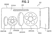
- Fig. 2 is an enlarged view of the charging port 22 of the electric vehicle 20.
- An opening portion 2202, a recess 2204, the outer lid member 2206, and the vehicle-side connectors 26 (26A, 26B) are provided in the charging port 22 of the electric vehicle 20.
- the opening portion 2202 is provided in the outer face of a vehicle body of the electric vehicle 20.
- the recess 2204 is sunken in an interior direction of the vehicle from the opening portion 2202.
- the outer lid member 2206 covers the opening portion 2202.
- the vehicle-side connectors 26 (26A, 26B) are provided inside the recess 2204 so that the charger-side connector 36 of the external charger 30 can be connected to one of the vehicle-side connectors 26 (26A, 26B).
- an illumination device 28 is provided inside the charging port 22 so that visibility of the periphery of the charging port 22 can be secured and charging work can be performed easily even when lightness in the periphery of the vehicle at night etc. is low.
- two vehicle-side connectors 26A and 26B are provided inside the charging port 22.
- the two vehicle-side connectors 26A and 26B are a rapid charging connection portion 26A and a normal charging connection portion 26B respectively.
- the two vehicle-side connectors 26A and 26B can be chosen according to the kind of the external charger 30 to be used.
- the two vehicle-side connectors 26A and 26B are disposed side by side laterally. Therefore, both the opening portion 2202 and the outer lid member 2206 covering the opening portion 2202 are formed into an oblong rectangle.
- the outer lid member 2206 is higher in size than that in a case where only one connector is provided.
- Each of the vehicle-side connectors 26 is provided with the vehicle-side coupling face 2602 (2602A, 2602B) and an inner lid member 2604 (2604A, 2604B) covering the vehicle-side coupling face 2602.
- a plug receptacle corresponding to various plugs provided in the charger-side coupling face 38 of the charger-side connector 36 is provided in the vehicle-side coupling face 2602.
- the outer lid member 2206 and one of the inner lid members 2604 are opened, the charger-side connector 36 is inserted into the charging port 22, and the charger-side coupling face 38 of the charger-side connector 36 and the vehicle-side coupling face 2602 of the corresponding vehicle-side connector 26 are connected to each other so that electric power can be transmitted/received therebetween.
- Fig. 3 is a block diagram showing a functional configuration of the electric vehicle 20.
- the electric vehicle 20 has a function of performing notification about an open/closed state of the outer lid member 2206 covering the vehicle-side connectors 26 mainly by processing of a vehicle ECU 10.
- the vehicle-side connectors 26 serve as interfaces for supplying driving energy of the own vehicle.
- the vehicle ECU 10 is constituted by a CPU, an ROM storing and saving a control program etc., an RAM serving as a working region of the control program, an EEPROM holding various data rewritably, an interface portion taking an interface with a peripheral circuit, etc.
- the vehicle ECU 10 When the CPU of the vehicle ECU 10 executes the control program, the vehicle ECU 10 functions as an opening/closing detecting portion 102, a connection detecting portion 104, a speed detecting portion 106, a shift detecting portion 108, and a notification portion 110.
- the opening/closing detecting portion 102 detects an open/closed state of the outer lid member 2206.
- the opening/closing detecting portion 102 detects an operating state of a charging lid opener which opens the outer lid member 2206, for example, due to an operation of a driver, so that the opening/closing detecting portion 102 can detect whether the outer lid member 2206 is in an open state or a closed state.
- a proximity sensor may be provided in the opening portion 2202 or the outer lid member 2206 of the charging port 22 to thereby detect whether the outer lid member 2206 is in an open state or a closed state.
- the connection detecting portion 104 detects a connection state of the external charger 30 (driving energy supply device) to one of the vehicle-side connectors 26 which is an interface for supplying driving energy. For example, the connection detecting portion 104 monitors a data communication status between the electric vehicle 20 and the external charger 30 to thereby detect whether the external charger 30 (charger-side connector 36) is connected to the vehicle-side connector 26 or not.
- a proximity sensor may be provided at the vehicle-side coupling face 2602 of the vehicle-side connector 26 i.e. a contact point between the vehicle-side connector 26 and the external charger 30 to thereby detect a connection status of the external charger 30 to the vehicle-side connector 26.
- the speed detecting portion 106 detects a running speed of the electric vehicle 20. For example, the speed detecting portion 106 acquires detection values of wheel speed sensors provided at respective wheels of the electric vehicle 20 to thereby calculate an average value of the detection values of the wheel speed sensors as the running speed of the electric vehicle 20.
- the shift detecting portion 108 detects an operating state on a shift lever 296 which serves as a shift setting portion of the electric vehicle 20.
- the shift detecting portion 108 is a sensor for detecting the position of the shift lever 296.
- the shift detecting portion 108 detects whether the operating state of the shift lever 296 is a shift range (such as a D range, a B range or an R range) in which the electric vehicle 20 is enabled to run or a shift range (such as a P range or an N range) in which the electric vehicle 20 is disabled from running.
- the notification portion 110 performs notification when the outer lid member 2206 is in an open state. That is, when it is detected by the opening/closing detecting portion 102 that the outer lid member 2206 is in the open state, the notification portion 110 notifies an occupant of the electric vehicle 20 of the detected fact.
- the notification portion 110 displays the fact that the outer lid member 2206 is in the open state on a display 292 provided on an interior of the electric vehicle 20. In this manner, the notification portion 110 performs notification visually.
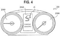
- Fig. 4 is an explanatory view of an example of the notification using the display 292.
- the display 292 is provided in an installment panel 29 which is provided to be opposed to a driver's seat.
- a display C including an icon of an attachment plug and a message indicating that "charging lid (outer lid member 2206) is open” is performed on the display 292. In this manner, the fact that the outer lid member 2206 is in the open state is notified.
- a speedometer 298 and a power meter 299 are provided in the installment panel 29.
- the speedometer 298 displays the running speed of the electric vehicle 20.
- the power meter 299 displays an input/output status of electric power of the driving battery.
- a warning lamp for indicating the fact that the outer lid member 2206 is in the open state may be provided in advance in place of the display 292.
- the warning lamp can be lit to perform notification.
- notification may be performed auditorily, for example, in such a manner that the fact that the outer lid member 2206 is in the open state is outputted by voice from a speaker 294 provided in the interior of the electric vehicle 20. Further, the fact that the outer lid member 2206 is in the open state may be notified, for example, by vibrating a steering wheel, the driver's seat, etc. of the electric vehicle 20.
- the notification portion 110 suspends the aforementioned notification when the external charger 30 is connected during the open state of the outer lid member 2206. That is, when it is detected by the connection detecting portion 104 that the external charger 30 is connected to the vehicle-side connector 26, the notification portion 110 does not perform the notification even during the open state of the outer lid member 2206.
- the vehicle-side coupling face 2602 of the vehicle-side connector 26 is not exposed in a state in which the external charger 30 is connected to the vehicle-side connector 26. Therefore, there is a low possibility that mischief may be done on the vehicle-side connector 26.
- the electric vehicle 20 cannot run in the state in which the external charger 30 is connected to the vehicle-side connector 26. Therefore, there occurs no damage on the outer lid member 2206 or an ambient object due to collusion of the outer lid member 2206. Even if the notification portion 110 notifies that the outer lid member 2206 is in the open state in such a state, the driver is expected to ignore the notification.
- the notification portion 110 suspends the notification which is likely to be unnecessary for the user to thereby reduce annoyance to the user. Accordingly, when the external charger 30 is connected during the open state of the outer lid member 2206, the notification portion 110 suspends the notification which is likely to be unnecessary for the user to thereby reduce annoyance to the user. As will be described later, the notification portion 110 performs the notification under more proper conditions to thereby enhance effectiveness of the notification.
- the fact that the open state of the outer lid member 2206 is in the open state is notified when the charging has been completed and the connection between the vehicle-side connector 26 and the external charger 30 has been released. Accordingly, the user can be prompted to close the outer lid member 2206 before starting running the vehicle.
- the notification portion 110 may change a notification mode according to the running state of the electric vehicle 20.
- Change patterns of the notification mode according to the running state of the electric vehicle 20 will be shown as follows. However, of the patterns 1 to 4, which processing to perform is determined, for example, based on setting from the user. In addition, without applying the following patterns 1 to 4, the notification portion 110 may always notify the user of the fact that the outer lid member 2206 is in the open state as long as the outer lid member 2206 is in the open state and connection between the vehicle-side connector 26 and the external charger 30 is released.
- ⁇ Pattern 1> Suspend notification as soon as the running speed of the vehicle becomes equal to or higher than a predetermined speed.
- the notification portion 110 performs notification in a case where the outer lid member 2206 is in an open state and the vehicle-side connector 26 and the external charger 30 are not connected to each other.
- the notification portion 110 continues the notification as long as the running speed is lower than the predetermined speed. However, as soon as the running speed becomes equal to or higher than the predetermined speed, the notification portion 110 suspends the notification.
- the notification portion 110 suspends the notification. In this manner, the notification portion 110 can suspend the notification which is likely to be unnecessary for the user so that annoyance to the user can be reduced.
- the notification portion 110 which has suspended the notification resumes the notification as soon as the vehicle speed changes to a low speed, for example, due to waiting for a traffic light etc. In this manner, the user can notice the notification easily.
- the predetermined speed may be set at an extremely low speed (e.g. a speed of 1 km per hour) etc. so that the notification portion 110 can suspend notification substantially when the vehicle starts running.
- an extremely low speed e.g. a speed of 1 km per hour
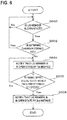
- Fig. 5 is a flow chart showing processing of the pattern 1.
- the vehicle ECU 10 detects an open/closed state of the outer lid member 2206 by the opening/closing detecting portion 102.
- the vehicle ECU 10 detects a connection state of the external charger 30 to the vehicle-side connector 26 by the connection detecting portion 104.
- the vehicle ECU 10 returns to the step S500 without performing notification to repeat the processings in and after the step S500.
- step S502 when the external charger 30 is not connected to the vehicle-side connector 26 in the step S502 (step S502: No), the notification portion 110 notifies that the outer lid member 2206 is in the open state (step S504).
- step S506 the notification portion 110 returns to the step S504 to continue the notification.
- step S506: Yes the notification portion 110 suspends the notification (step S508).
- ⁇ Pattern 2> Change a current notification method to another method as soon as the running speed of the vehicle becomes equal to or higher than the predetermined speed.
- the notification portion 110 can perform notification by a plurality of notification methods such as display and voice. That is, when the outer lid member 2206 is in an open state and the vehicle-side connector 26 and the external charger 30 are not connected to each other, the notification portion 110 first starts notification by a first method (e.g. display on the display 292). When the electric vehicle 20 then starts running, the notification portion 110 continues the notification by the first method as long as the running speed is lower than the predetermined speed. As soon as the running speed becomes equal to or higher than the predetermined speed, the notification portion 110 changes over to notification by a second method (e.g. output of a voice message). On this occasion, the notification portion 110 may continue the notification by the first method in addition to the notification by the second method. In addition, at the timing when the running speed becomes equal to or higher than the predetermined speed, the notification portion 110 may perform the notification by the second method for a predetermined time and then suspend the notification as in the pattern 1.
- a first method e.g. display on the display 292
- the notification portion 110 changes over
- the pattern 2 in a case where the user does not close the outer lid member 2206 in spite of the notification performed between before the vehicle starts running and immediately after the vehicle starts running (the speed is lower than the predetermined speed), it is determined that the contents of the notification are likely to be not transmitted to the user because the notification method is not suited to a user's situation.
- the notification method In some condition such as under backlight or during occurrence of smog, the user may pay much attention to the outside of the vehicle in order to confirm an ambient situation. Therefore, there is a possibility that the notification using display may be hardly transmitted to the user.
- the notification using voice may be hardly transmitted to the user.
- the notification method is changed as in the pattern 2, the contents of the notification can be transmitted to the user easily.
- the predetermined speed may be set at an extremely low speed (e.g. a speed of 1 km per hour) etc. so that the notification method can be changed to another substantially when the vehicle starts running.
- an extremely low speed e.g. a speed of 1 km per hour
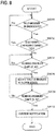
- Fig. 6 is a flow chart showing processing of the pattern 2.
- Steps S600 and S602 are the same as the steps S500 and S502 in Fig. 5 . Therefore, description about the steps S600 and S602 will be omitted.
- the notification portion 110 first notifies that the outer lid member 2206 is in the open state by a first method (such as display) (step S604).
- step S606 the notification portion 110 returns to the step S604 to continue the notification by the first method.
- step S606: Yes the notification portion 110 notifies that the outer lid member 2206 is in the open state by a second method (such as voice) (step S608).
- ⁇ Pattern 3> Suspend notification once when the vehicle starts running, and resume the notification as soon as the running speed of the vehicle becomes equal to or higher than a predetermined speed.
- the notification portion 110 performs notification.
- the notification portion 110 suspends the notification once.
- the notification portion 110 resumes the notification.
- the notification portion 110 suspends the notification once when the vehicle running starts.
- the notification which is likely to be unnecessary for the user can be suspended so that annoyance to the user can be reduced.
- the notification portion 110 resumes the notification before the running speed reaches a higher speed. In this manner, the user's intention can be reconfirmed. For example, the user who is overloaded with confirmation of an ambient situation prior to the start of the vehicle running is not aware of the notification. In such a case, the notification suspended once is resumed at a point of time when the running situation is conceived to be stable. In this manner, the user can notice the notification easily.
- the timing of suspending the notification once may be set not at the timing when the vehicle starts running but at a timing when the running speed becomes equal to or higher than a first predetermined speed, and the timing of resuming the notification may be set at a timing when the running speed becomes equal to or higher than a second predetermined speed (> the first predetermined speed).
- Fig. 7 is a flow chart showing processing of the pattern 3.
- Steps S700 and S702 are the same as the steps S500 and S502 in Fig. 5 . Therefore, description about the steps S700 and S702 will be omitted.
- step S700: Yes When the outer lid member 2206 is in an open state (step S700: Yes) and the external charger 300 is not connected to the vehicle-side connector 26 (step S702: No), the notification portion 110 notifies that the outer lid member 2206 is in the open state (step S704).
- step S706 Unless the electric vehicle 20 starts running (loop for step S706: No), the notification portion 110 returns to the step S704 to continue the notification.
- step S706: Yes the notification portion 110 suspends the notification (step S708).
- step S710: No the notification portion 110 continues the state in which the notification is suspended. As soon as the running speed becomes equal to or higher than the predetermined speed (step S710: Yes), the notification portion 110 resumes the notification about the open state of the outer lid member 2206 (step S712).
- ⁇ Pattern 4> Suspend notification when the shift lever 296 is operated to a shift range where the vehicle is enabled to run.
- the notification portion 110 performs notification.
- the shift range is expected to be set at the shift range such as the P range or the N range where the vehicle is disabled from running. Therefore, notification is expected to be performed immediately after the connection between the vehicle-side connector 26 and the external charger 30 is released.
- the shift lever 296 shift setting portion
- the notification portion 110 suspends the notification.
- the notification portion 110 suspends the notification when the user shows his/her intention to run the vehicle (in the case where the user makes operation to change the shift range to the D range, the B range, the R range, or the like). In this manner, the notification portion 110 can suspend the notification which is likely to be unnecessary for the user so that annoyance to the user can be reduced.
- the notification may be resumed as soon as the running speed becomes equal to or higher than a predetermined speed, in the same manner as in the pattern 3.
- Fig. 8 is a flow chart showing processing of the pattern 4.
- Steps S800 and S802 are the same as the steps S500 and S502 in Fig. 5 . Therefore, description about the steps S800 and S802 will be omitted.
- step S800: Yes When the outer lid member 2206 is in an open state (step S800: Yes) and the external charger 300 is not connected to the vehicle-side connector 26 (step S802: No), the notification portion 110 determines whether the shift lever 296 is operated to a shift range (such as the P range or the N range) where the vehicle is disabled from running or not (loop for step S804: No).
- a shift range such as the P range or the N range
- the notification portion 110 notifies that the outer lid member 2206 is in the open state (step S806).
- step S808: No While the shift lever 296 is operated to the shift range (such as the P range or the N range) where the vehicle is disabled from running (loop for step S808: No), the notification portion 110 returns to the step S806 to continue the notification.
- the shift lever 296 is operated to a shift range (such as the D range, the B range or the R range) where the vehicle is enabled to run (step S808: Yes)
- the notification portion 110 suspends the notification (step S810).
- the notification about the open state of the outer lid member 2206 is suspended.
- the notification which is likely to be unnecessary for the user is suspended so that annoyance to the user can be reduced.
- the notification is performed under more proper conditions so that effectiveness of the notification can be enhanced advantageously.
- notification is suspended as soon as the running speed of the vehicle becomes equal to or higher than the predetermined speed.
- pattern 1 the notification which is likely to be unnecessary for the user is suspended so that annoyance to the user can be reduced advantageously.
- the notification is resumed as soon as the running speed changes to a low speed, for example, due to waiting for a traffic signal etc.
- the notification can be easily noticed by the user advantageously.
- the notification method is changed between the case where the running speed of the vehicle is lower than the predetermined speed and the case where the running speed of the vehicle is equal to or higher than the predetermined speed.
- pattern 2 the contents of the notification can be more surely transmitted to the user advantageously.
- notification is suspended once when the vehicle starts running.
- the notification is resumed as soon as the running speed of the vehicle becomes equal to or higher than the predetermined speed.
- pattern 3 the notification which is likely to be unnecessary for the user is suspended so that annoyance to the user can be reduced.
- the notification is resumed in consideration of a case where the user is not aware of the notification prior to the start of the vehicle running. Accordingly, unexpected damage etc. on the lid member can be prevented advantageously.
- notification is suspended when the shift lever 296 is operated to the shift range where the vehicle is enabled to run.
- pattern 4 the notification which is likely to be unnecessary for the user can be suspended so that annoyance to the user can be reduced.
- the embodiment has been described in the case where the vehicle according to the invention is regarded as an electric vehicle using electric power as driving energy.
- the invention is not limited thereto but may be applied to a vehicle using fuel (such as gasoline, methanol or hydrogen) as driving energy.
- the outer lid member 2206 corresponds to a lid member.
- the invention is not limited thereto, but may be applied to the inner lid members 2604 which cover the vehicle-side coupling faces 2602.
Landscapes
- Engineering & Computer Science (AREA)
- Power Engineering (AREA)
- Mechanical Engineering (AREA)
- Transportation (AREA)
- Chemical & Material Sciences (AREA)
- Combustion & Propulsion (AREA)
- General Engineering & Computer Science (AREA)
- Life Sciences & Earth Sciences (AREA)
- Sustainable Development (AREA)
- Sustainable Energy (AREA)
- Human Computer Interaction (AREA)
- Electric Propulsion And Braking For Vehicles (AREA)
Abstract
Description
- The present invention relates to a vehicle.
- According to the background art, there has been known a technique for preventing a vehicle from running while a lid member remains in an open state. The lid member serves for protecting an interface (e.g. a charging connector or an oil feeding port) which is provided in the vehicle in order to make connection with a driving energy supply device (e.g. a charger or an oil feeding machine). This is because the lid member may hit against the surroundings to be damaged when the vehicle runs while the lid member remains in the open state. In addition, this is also because mischief may be done on the interface or foreign matters may adhere to the interface when the lid member is open to expose the interface.
- For example,
JP-A-2002-2428 - The aforementioned technique is effective in being capable of notifying the user of the fact that the lid member is in the open state when the user does not recognize the fact. However, the user may feel it inconvenient in such a case where the user has to run the vehicle while recognizing that the lid member is in the open state, for example, when the lid member is deformed too much to move to a position which can be recognized as a closed state, or when a mechanism for opening/closing the lid member does not function temporarily due to freezing etc. In addition, when such notification continues as a normal practice, it may become difficult for the user to notice the notification, thereby deteriorating effectiveness of the notification.
- The invention has been accomplished in consideration of such circumstances. An object of the invention is to notify that a lid member covering an interface for supplying driving energy of a vehicle is in an open state at a proper timing to thereby improve effectiveness of the notification.
- According to an aspect of the invention, a vehicle that performs notification about an open/closed state of a lid member covering an interface for supplying driving energy includes a notification portion that performs notification when the lid member is in the open state and a connection detecting portion that detects a connection state of a driving energy supply device to the interface. In the vehicle, the notification portion suspends notification when the driving energy supply device is connected to the interface during the open state of the lid member.
- According to the above configuration, when the driving energy supply device is connected to the interface while the lid member covering the interface is in the open state, notification about the open state of the lid member is suspended. Thus, the notification which is likely to be unnecessary for the user is suspended so that annoyance to the user can be reduced. In addition, the notification is performed under more proper conditions so that effectiveness of the notification can be enhanced advantageously.
-
-
Fig. 1 is an explanatory view showing external appearance of anelectric vehicle 20. -
Fig. 2 is an enlarged view of acharging port 22 of theelectric vehicle 20. -
Fig. 3 is a block diagram showing a functional configuration of theelectric vehicle 20. -
Fig. 4 is an explanatory view of an example of notification using adisplay 292. -
Fig. 5 is a flow chart showing processing of a pattern 1. -
Fig. 6 is a flow chart showing processing of a pattern 2. -
Fig. 7 is a flow chart showing processing of a pattern 3. -
Fig. 8 is a flow chart showing processing of a pattern 4. - A preferred embodiment of a vehicle according to the invention will be described below in detail with reference to the accompanying drawings.
- In the embodiment, the vehicle according to the invention is regarded as an
electric vehicle 20. That is, it is assumed that the vehicle according to the invention uses electric power as driving energy of the vehicle and a driving energy supply device is anexternal charger 30. -
Fig. 1 is an explanatory view showing external appearance of theelectric vehicle 20. - The
electric vehicle 20 according to the embodiment has a driving battery which stores driving electric power of a driving motor of the vehicle. Theelectric vehicle 20 runs using electric power as at least a portion of the driving energy. - A
charging port 22 is provided in an outer face of theelectric vehicle 20. Thecharging port 22 is covered with an outer lid member 2206 (charging lid). Thecharging port 22 houses vehicle-side connectors 26 (26A, 26B) to one of which a charger-side connector 36 of theexternal charger 30 is connected for charging theelectric vehicle 20. In the embodiment, the vehicle-side connectors 26 (26A, 26B) correspond to an interface for supplying driving energy, and theouter lid member 2206 corresponds to a lid member. - The
external charger 30 corresponds to a driving energy supply device. Theexternal charger 30 supplies electric power to the driving battery (not shown) mounted in theelectric vehicle 20. - The
external charger 30 is configured to include abody portion 32, acharging cable 34, and the charger-side connector 36. A control portion (charging controller) for controlling operation of theexternal charger 30, a user interface for displaying a charging state of theexternal charger 30, charging setting, an operation screen etc., etc. are provided in thebody portion 32. - The
charging cable 34 is extended from thebody portion 32. The charger-side connector 36 is provided at a front end of thecharging cable 34. A charger-side coupling face 38 to be connected to one of vehicle-side coupling faces 2602 (seeFig. 2 ) of the vehicle-side connectors 26 is provided at a front end of the charger-side connector 36. An electric power supply plug for supplying electric power to theelectric vehicle 20 and a data plug for exchanging data with theelectric vehicle 20 are provided in the charger-side coupling face 38. -
Fig. 2 is an enlarged view of thecharging port 22 of theelectric vehicle 20. - An
opening portion 2202, arecess 2204, theouter lid member 2206, and the vehicle-side connectors 26 (26A, 26B) are provided in thecharging port 22 of theelectric vehicle 20. Theopening portion 2202 is provided in the outer face of a vehicle body of theelectric vehicle 20. Therecess 2204 is sunken in an interior direction of the vehicle from theopening portion 2202. Theouter lid member 2206 covers theopening portion 2202. The vehicle-side connectors 26 (26A, 26B) are provided inside therecess 2204 so that the charger-side connector 36 of theexternal charger 30 can be connected to one of the vehicle-side connectors 26 (26A, 26B). - In addition, an
illumination device 28 is provided inside thecharging port 22 so that visibility of the periphery of thecharging port 22 can be secured and charging work can be performed easily even when lightness in the periphery of the vehicle at night etc. is low. - In the embodiment, two vehicle-
side connectors charging port 22. The two vehicle-side connectors charging connection portion 26A and a normalcharging connection portion 26B respectively. The two vehicle-side connectors external charger 30 to be used. The two vehicle-side connectors opening portion 2202 and theouter lid member 2206 covering theopening portion 2202 are formed into an oblong rectangle. Theouter lid member 2206 is higher in size than that in a case where only one connector is provided. - Each of the vehicle-side connectors 26 (26A, 26B) is provided with the vehicle-side coupling face 2602 (2602A, 2602B) and an inner lid member 2604 (2604A, 2604B) covering the vehicle-side coupling face 2602. A plug receptacle corresponding to various plugs provided in the charger-
side coupling face 38 of the charger-side connector 36 is provided in the vehicle-side coupling face 2602. During charging of theelectric vehicle 20, theouter lid member 2206 and one of the inner lid members 2604 are opened, the charger-side connector 36 is inserted into thecharging port 22, and the charger-side coupling face 38 of the charger-side connector 36 and the vehicle-side coupling face 2602 of the corresponding vehicle-side connector 26 are connected to each other so that electric power can be transmitted/received therebetween. -
Fig. 3 is a block diagram showing a functional configuration of theelectric vehicle 20. - The
electric vehicle 20 has a function of performing notification about an open/closed state of theouter lid member 2206 covering the vehicle-side connectors 26 mainly by processing of avehicle ECU 10. The vehicle-side connectors 26 serve as interfaces for supplying driving energy of the own vehicle. - The
vehicle ECU 10 is constituted by a CPU, an ROM storing and saving a control program etc., an RAM serving as a working region of the control program, an EEPROM holding various data rewritably, an interface portion taking an interface with a peripheral circuit, etc. - When the CPU of the
vehicle ECU 10 executes the control program, thevehicle ECU 10 functions as an opening/closing detecting portion 102, aconnection detecting portion 104, aspeed detecting portion 106, ashift detecting portion 108, and anotification portion 110. - The opening/
closing detecting portion 102 detects an open/closed state of theouter lid member 2206. The opening/closing detecting portion 102 detects an operating state of a charging lid opener which opens theouter lid member 2206, for example, due to an operation of a driver, so that the opening/closing detecting portion 102 can detect whether theouter lid member 2206 is in an open state or a closed state. In addition, for example, a proximity sensor may be provided in theopening portion 2202 or theouter lid member 2206 of the chargingport 22 to thereby detect whether theouter lid member 2206 is in an open state or a closed state. - The
connection detecting portion 104 detects a connection state of the external charger 30 (driving energy supply device) to one of the vehicle-side connectors 26 which is an interface for supplying driving energy. For example, theconnection detecting portion 104 monitors a data communication status between theelectric vehicle 20 and theexternal charger 30 to thereby detect whether the external charger 30 (charger-side connector 36) is connected to the vehicle-side connector 26 or not. In addition, for example, a proximity sensor may be provided at the vehicle-side coupling face 2602 of the vehicle-side connector 26 i.e. a contact point between the vehicle-side connector 26 and theexternal charger 30 to thereby detect a connection status of theexternal charger 30 to the vehicle-side connector 26. - The
speed detecting portion 106 detects a running speed of theelectric vehicle 20. For example, thespeed detecting portion 106 acquires detection values of wheel speed sensors provided at respective wheels of theelectric vehicle 20 to thereby calculate an average value of the detection values of the wheel speed sensors as the running speed of theelectric vehicle 20. - The
shift detecting portion 108 detects an operating state on ashift lever 296 which serves as a shift setting portion of theelectric vehicle 20. For example, theshift detecting portion 108 is a sensor for detecting the position of theshift lever 296. Theshift detecting portion 108 detects whether the operating state of theshift lever 296 is a shift range (such as a D range, a B range or an R range) in which theelectric vehicle 20 is enabled to run or a shift range (such as a P range or an N range) in which theelectric vehicle 20 is disabled from running. - The
notification portion 110 performs notification when theouter lid member 2206 is in an open state. That is, when it is detected by the opening/closing detecting portion 102 that theouter lid member 2206 is in the open state, thenotification portion 110 notifies an occupant of theelectric vehicle 20 of the detected fact. - For example, the
notification portion 110 displays the fact that theouter lid member 2206 is in the open state on adisplay 292 provided on an interior of theelectric vehicle 20. In this manner, thenotification portion 110 performs notification visually. -
Fig. 4 is an explanatory view of an example of the notification using thedisplay 292. - For example, the
display 292 is provided in aninstallment panel 29 which is provided to be opposed to a driver's seat. In the example ofFig. 4 , a display C including an icon of an attachment plug and a message indicating that "charging lid (outer lid member 2206) is open" is performed on thedisplay 292. In this manner, the fact that theouter lid member 2206 is in the open state is notified. - Incidentally, in addition to the
display 292, aspeedometer 298 and apower meter 299 are provided in theinstallment panel 29. Thespeedometer 298 displays the running speed of theelectric vehicle 20. Thepower meter 299 displays an input/output status of electric power of the driving battery. - In addition, a warning lamp for indicating the fact that the
outer lid member 2206 is in the open state may be provided in advance in place of thedisplay 292. Thus, the warning lamp can be lit to perform notification. - In addition, in addition to the aforementioned notification performed visually, notification may be performed auditorily, for example, in such a manner that the fact that the
outer lid member 2206 is in the open state is outputted by voice from aspeaker 294 provided in the interior of theelectric vehicle 20. Further, the fact that theouter lid member 2206 is in the open state may be notified, for example, by vibrating a steering wheel, the driver's seat, etc. of theelectric vehicle 20. - Here, the
notification portion 110 suspends the aforementioned notification when theexternal charger 30 is connected during the open state of theouter lid member 2206. That is, when it is detected by theconnection detecting portion 104 that theexternal charger 30 is connected to the vehicle-side connector 26, thenotification portion 110 does not perform the notification even during the open state of theouter lid member 2206. - The vehicle-side coupling face 2602 of the vehicle-
side connector 26 is not exposed in a state in which theexternal charger 30 is connected to the vehicle-side connector 26. Therefore, there is a low possibility that mischief may be done on the vehicle-side connector 26. In addition, theelectric vehicle 20 cannot run in the state in which theexternal charger 30 is connected to the vehicle-side connector 26. Therefore, there occurs no damage on theouter lid member 2206 or an ambient object due to collusion of theouter lid member 2206. Even if thenotification portion 110 notifies that theouter lid member 2206 is in the open state in such a state, the driver is expected to ignore the notification. Accordingly, when theexternal charger 30 is connected during the open state of theouter lid member 2206, thenotification portion 110 suspends the notification which is likely to be unnecessary for the user to thereby reduce annoyance to the user. As will be described later, thenotification portion 110 performs the notification under more proper conditions to thereby enhance effectiveness of the notification. - Incidentally, the fact that the open state of the
outer lid member 2206 is in the open state is notified when the charging has been completed and the connection between the vehicle-side connector 26 and theexternal charger 30 has been released. Accordingly, the user can be prompted to close theouter lid member 2206 before starting running the vehicle. - In addition, there is a case where the user has to run the vehicle while recognizing that the
outer lid member 2206 is in the open state, for example, when theouter lid member 2206 is deformed too much to move to a position which can be recognized as the closed state, or when a mechanism for opening/closing theouter lid member 2206 does not function temporarily due to freezing etc. In this case, the user may feel annoyed to be notified of the fact that theouter lid member 2206 is in the open state. - Accordingly, the
notification portion 110 may change a notification mode according to the running state of theelectric vehicle 20. - Change patterns of the notification mode according to the running state of the
electric vehicle 20 will be shown as follows. However, of the patterns 1 to 4, which processing to perform is determined, for example, based on setting from the user. In addition, without applying the following patterns 1 to 4, thenotification portion 110 may always notify the user of the fact that theouter lid member 2206 is in the open state as long as theouter lid member 2206 is in the open state and connection between the vehicle-side connector 26 and theexternal charger 30 is released. - <Pattern 1> Suspend notification as soon as the running speed of the vehicle becomes equal to or higher than a predetermined speed.
- According to the pattern 1, the
notification portion 110 performs notification in a case where theouter lid member 2206 is in an open state and the vehicle-side connector 26 and theexternal charger 30 are not connected to each other. When theelectric vehicle 20 starts running, thenotification portion 110 continues the notification as long as the running speed is lower than the predetermined speed. However, as soon as the running speed becomes equal to or higher than the predetermined speed, thenotification portion 110 suspends the notification. - According to the pattern 1, in a case where the user does not close the
outer lid member 2206 in spite of the notification performed between before the vehicle starts running and immediately after the vehicle starts running (the speed is lower than the predetermined speed), it is determined that the open state is continued due to user's intention. Therefore, thenotification portion 110 suspends the notification. In this manner, thenotification portion 110 can suspend the notification which is likely to be unnecessary for the user so that annoyance to the user can be reduced. In addition, for example, the user who is overloaded with confirmation of an ambient situation around the start of the vehicle running is not aware of the notification. In such a case, thenotification portion 110 which has suspended the notification resumes the notification as soon as the vehicle speed changes to a low speed, for example, due to waiting for a traffic light etc. In this manner, the user can notice the notification easily. - Incidentally, the predetermined speed may be set at an extremely low speed (e.g. a speed of 1 km per hour) etc. so that the
notification portion 110 can suspend notification substantially when the vehicle starts running. -
Fig. 5 is a flow chart showing processing of the pattern 1. - The
vehicle ECU 10 detects an open/closed state of theouter lid member 2206 by the opening/closing detecting portion 102. When theouter lid member 2206 is in the open state (step S500: Yes), thevehicle ECU 10 detects a connection state of theexternal charger 30 to the vehicle-side connector 26 by theconnection detecting portion 104. When theexternal charger 30 is connected to the vehicle-side connector 26 (step S502: Yes) or when theouter lid member 2206 is in the closed state in the step S500 (step S500: No), thevehicle ECU 10 returns to the step S500 without performing notification to repeat the processings in and after the step S500. - On the other hand, when the
external charger 30 is not connected to the vehicle-side connector 26 in the step S502 (step S502: No), thenotification portion 110 notifies that theouter lid member 2206 is in the open state (step S504). - Then, the
electric vehicle 20 starts running. Unless the running speed becomes equal to or higher than a predetermined speed (loop for step S506: No), thenotification portion 110 returns to the step S504 to continue the notification. When the running speed becomes equal to or higher than the predetermined speed (step S506: Yes), thenotification portion 110 suspends the notification (step S508). - <Pattern 2> Change a current notification method to another method as soon as the running speed of the vehicle becomes equal to or higher than the predetermined speed.
- According to the pattern 2, it is assumed that the
notification portion 110 can perform notification by a plurality of notification methods such as display and voice. That is, when theouter lid member 2206 is in an open state and the vehicle-side connector 26 and theexternal charger 30 are not connected to each other, thenotification portion 110 first starts notification by a first method (e.g. display on the display 292). When theelectric vehicle 20 then starts running, thenotification portion 110 continues the notification by the first method as long as the running speed is lower than the predetermined speed. As soon as the running speed becomes equal to or higher than the predetermined speed, thenotification portion 110 changes over to notification by a second method (e.g. output of a voice message). On this occasion, thenotification portion 110 may continue the notification by the first method in addition to the notification by the second method. In addition, at the timing when the running speed becomes equal to or higher than the predetermined speed, thenotification portion 110 may perform the notification by the second method for a predetermined time and then suspend the notification as in the pattern 1. - According to the pattern 2, in a case where the user does not close the
outer lid member 2206 in spite of the notification performed between before the vehicle starts running and immediately after the vehicle starts running (the speed is lower than the predetermined speed), it is determined that the contents of the notification are likely to be not transmitted to the user because the notification method is not suited to a user's situation. In some condition such as under backlight or during occurrence of smog, the user may pay much attention to the outside of the vehicle in order to confirm an ambient situation. Therefore, there is a possibility that the notification using display may be hardly transmitted to the user. In addition, in some condition such as during a large amount of rainfall or a large volume of ambient traffic or during use of a car stereo device, there is a possibility that the notification using voice may be hardly transmitted to the user. When the notification method is changed as in the pattern 2, the contents of the notification can be transmitted to the user easily. - Incidentally, the predetermined speed may be set at an extremely low speed (e.g. a speed of 1 km per hour) etc. so that the notification method can be changed to another substantially when the vehicle starts running.
-
Fig. 6 is a flow chart showing processing of the pattern 2. - Steps S600 and S602 are the same as the steps S500 and S502 in
Fig. 5 . Therefore, description about the steps S600 and S602 will be omitted. - When the
outer lid member 2206 is in an open state (step S600: Yes) and the external charger 300 is not connected to the vehicle-side connector 26 (step S602: No), thenotification portion 110 first notifies that theouter lid member 2206 is in the open state by a first method (such as display) (step S604). - Then, the
electric vehicle 20 starts running. Unless the running speed of theelectric vehicle 20 becomes equal to or higher than a predetermined speed (loop for step S606: No), thenotification portion 110 returns to the step S604 to continue the notification by the first method. As soon as the running speed becomes equal to or higher than the predetermined speed (step S606: Yes), thenotification portion 110 notifies that theouter lid member 2206 is in the open state by a second method (such as voice) (step S608). - <Pattern 3> Suspend notification once when the vehicle starts running, and resume the notification as soon as the running speed of the vehicle becomes equal to or higher than a predetermined speed.
- According to the pattern 3, when the
outer lid member 2206 is in an open state and the vehicle-side connector 26 and theexternal charger 30 are not connected to each other, thenotification portion 110 performs notification. When theelectric vehicle 20 starts running, thenotification portion 110 suspends the notification once. As soon as the running speed becomes equal to or higher than the predetermined speed, thenotification portion 110 resumes the notification. - According to the pattern 3, in a case where the user does not close the
outer lid member 2206 in spite of the notification performed between before the vehicle starts running and when the vehicle starts running, it is determined that the open state is continued due to user's intention. Therefore, thenotification portion 110 suspends the notification once when the vehicle running starts. Thus, the notification which is likely to be unnecessary for the user can be suspended so that annoyance to the user can be reduced. In consideration of a case where the user is not aware of the notification prior to the start of the vehicle running, thenotification portion 110 resumes the notification before the running speed reaches a higher speed. In this manner, the user's intention can be reconfirmed. For example, the user who is overloaded with confirmation of an ambient situation prior to the start of the vehicle running is not aware of the notification. In such a case, the notification suspended once is resumed at a point of time when the running situation is conceived to be stable. In this manner, the user can notice the notification easily. - Incidentally, the timing of suspending the notification once may be set not at the timing when the vehicle starts running but at a timing when the running speed becomes equal to or higher than a first predetermined speed, and the timing of resuming the notification may be set at a timing when the running speed becomes equal to or higher than a second predetermined speed (> the first predetermined speed).
-
Fig. 7 is a flow chart showing processing of the pattern 3. - Steps S700 and S702 are the same as the steps S500 and S502 in
Fig. 5 . Therefore, description about the steps S700 and S702 will be omitted. - When the
outer lid member 2206 is in an open state (step S700: Yes) and the external charger 300 is not connected to the vehicle-side connector 26 (step S702: No), thenotification portion 110 notifies that theouter lid member 2206 is in the open state (step S704). - Unless the
electric vehicle 20 starts running (loop for step S706: No), thenotification portion 110 returns to the step S704 to continue the notification. When theelectric vehicle 20 starts running (step S706: Yes), thenotification portion 110 suspends the notification (step S708). - Then, unless the running speed becomes equal to or higher than a predetermined speed (loop for step S710: No), the
notification portion 110 continues the state in which the notification is suspended. As soon as the running speed becomes equal to or higher than the predetermined speed (step S710: Yes), thenotification portion 110 resumes the notification about the open state of the outer lid member 2206 (step S712). - <Pattern 4> Suspend notification when the
shift lever 296 is operated to a shift range where the vehicle is enabled to run. - According to the pattern 4, when the
outer lid member 2206 is in an open state, the vehicle-side connector 26 and theexternal charger 30 are not connected to each other, and the shift range is set at a shift range such as a P range or an N range where the vehicle is disabled from running, thenotification portion 110 performs notification. Incidentally, generally, while the vehicle-side connector 26 and theexternal charger 30 are connected to each other, the shift range is expected to be set at the shift range such as the P range or the N range where the vehicle is disabled from running. Therefore, notification is expected to be performed immediately after the connection between the vehicle-side connector 26 and theexternal charger 30 is released. When the shift lever 296 (shift setting portion) is then operated to a shift range such as a D range, a B range or an R range where the vehicle is enabled to run, thenotification portion 110 suspends the notification. - According to the pattern 4, in a case where the user does not close the
outer lid member 2206 in spite of the notification performed during stop of the vehicle (when the shift range is located at the P range or the N range), it is determined that the open state is continued due to user's intention. Therefore, thenotification portion 110 suspends the notification when the user shows his/her intention to run the vehicle (in the case where the user makes operation to change the shift range to the D range, the B range, the R range, or the like). In this manner, thenotification portion 110 can suspend the notification which is likely to be unnecessary for the user so that annoyance to the user can be reduced. - Incidentally, also in the pattern 4, after the notification is suspended, the notification may be resumed as soon as the running speed becomes equal to or higher than a predetermined speed, in the same manner as in the pattern 3.
-
Fig. 8 is a flow chart showing processing of the pattern 4. - Steps S800 and S802 are the same as the steps S500 and S502 in
Fig. 5 . Therefore, description about the steps S800 and S802 will be omitted. - When the
outer lid member 2206 is in an open state (step S800: Yes) and the external charger 300 is not connected to the vehicle-side connector 26 (step S802: No), thenotification portion 110 determines whether theshift lever 296 is operated to a shift range (such as the P range or the N range) where the vehicle is disabled from running or not (loop for step S804: No). - When the
shift lever 296 is operated to the shift range (such as the P range or the N range) where the vehicle is disabled from running (step S804: Yes), thenotification portion 110 notifies that theouter lid member 2206 is in the open state (step S806). - While the
shift lever 296 is operated to the shift range (such as the P range or the N range) where the vehicle is disabled from running (loop for step S808: No), thenotification portion 110 returns to the step S806 to continue the notification. When theshift lever 296 is operated to a shift range (such as the D range, the B range or the R range) where the vehicle is enabled to run (step S808: Yes), thenotification portion 110 suspends the notification (step S810). - According to the
electric vehicle 20 according to the embodiment as described above, when theexternal charger 30 is connected to the vehicle-side connector 26 while theouter lid member 2206 covering the vehicle-side connector 26 is in an open state, notification about the open state of theouter lid member 2206 is suspended. In this manner, the notification which is likely to be unnecessary for the user is suspended so that annoyance to the user can be reduced. In addition, the notification is performed under more proper conditions so that effectiveness of the notification can be enhanced advantageously. - In addition, in the
electric vehicle 20, notification is suspended as soon as the running speed of the vehicle becomes equal to or higher than the predetermined speed. With this configuration (pattern 1), the notification which is likely to be unnecessary for the user is suspended so that annoyance to the user can be reduced advantageously. In addition, after the notification has been suspended once, the notification is resumed as soon as the running speed changes to a low speed, for example, due to waiting for a traffic signal etc. Thus, the notification can be easily noticed by the user advantageously. - In addition, in the
electric vehicle 20, the notification method is changed between the case where the running speed of the vehicle is lower than the predetermined speed and the case where the running speed of the vehicle is equal to or higher than the predetermined speed. With this configuration (pattern 2), the contents of the notification can be more surely transmitted to the user advantageously. - In addition, in the
electric vehicle 20, notification is suspended once when the vehicle starts running. In addition, the notification is resumed as soon as the running speed of the vehicle becomes equal to or higher than the predetermined speed. With this configuration (pattern 3), the notification which is likely to be unnecessary for the user is suspended so that annoyance to the user can be reduced. In addition, the notification is resumed in consideration of a case where the user is not aware of the notification prior to the start of the vehicle running. Accordingly, unexpected damage etc. on the lid member can be prevented advantageously. - In addition, in the
electric vehicle 20, notification is suspended when theshift lever 296 is operated to the shift range where the vehicle is enabled to run. With this configuration (pattern 4), the notification which is likely to be unnecessary for the user can be suspended so that annoyance to the user can be reduced. - Incidentally, the embodiment has been described in the case where the vehicle according to the invention is regarded as an electric vehicle using electric power as driving energy. However, the invention is not limited thereto but may be applied to a vehicle using fuel (such as gasoline, methanol or hydrogen) as driving energy.
- In addition, in the embodiment, the
outer lid member 2206 corresponds to a lid member. However, the invention is not limited thereto, but may be applied to the inner lid members 2604 which cover the vehicle-side coupling faces 2602.
Claims (5)
- A vehicle that performs notification about an open/closed state of a lid member covering an interface for supplying driving energy, the vehicle comprising:a notification portion that performs notification when the lid member is in the open state; anda connection detecting portion that detects a connection state of a driving energy supply device to the interface; wherein:the notification portion suspends notification when the driving energy supply device is connected to the interface during the open state of the lid member.
- The vehicle according to claim 1 further comprising a speed detecting portion that detects a running speed of the vehicle,
wherein the notification portion suspends notification when the running speed of the vehicle becomes equal to or higher than a predetermined speed during the open state of the lid member. - The vehicle according to claim 1 further comprising a speed detecting portion that detects a running speed of the vehicle,
wherein the notification portion is capable of notification about the open state of the lid member with a plurality of notification methods, and
the notification portion change a current notification method to another when the running speed of the vehicle becomes equal to or higher than a predetermined speed during the open state of the lid member. - The vehicle according to claim 1 further comprising a speed detecting portion that detects a running speed of the vehicle,
wherein the notification portion suspends notification when the vehicle starts running during the open state of the lid member, and
the notification portion resumes the notification when the running speed of the vehicle becomes equal to or higher than a predetermined speed. - The vehicle according to claim 1 further comprising a shift detecting portion that detects an operation state on a shift setting portion of the vehicle,
wherein the notification portion suspends notification when the shift setting portion is operated to a shift range where the vehicle is enabled to run.
Applications Claiming Priority (1)
| Application Number | Priority Date | Filing Date | Title |
|---|---|---|---|
| JP2016224016A JP6708100B2 (en) | 2016-11-17 | 2016-11-17 | vehicle |
Publications (2)
| Publication Number | Publication Date |
|---|---|
| EP3323660A1 true EP3323660A1 (en) | 2018-05-23 |
| EP3323660B1 EP3323660B1 (en) | 2020-09-23 |
Family
ID=60382115
Family Applications (1)
| Application Number | Title | Priority Date | Filing Date |
|---|---|---|---|
| EP17202063.8A Active EP3323660B1 (en) | 2016-11-17 | 2017-11-16 | Electric vehicle charged by external power supply |
Country Status (4)
| Country | Link |
|---|---|
| US (1) | US10655590B2 (en) |
| EP (1) | EP3323660B1 (en) |
| JP (1) | JP6708100B2 (en) |
| CN (1) | CN108068622B (en) |
Families Citing this family (7)
| Publication number | Priority date | Publication date | Assignee | Title |
|---|---|---|---|---|
| JP7225605B2 (en) * | 2018-08-22 | 2023-02-21 | スズキ株式会社 | Vehicle charging lid opener |
| JP6787959B2 (en) * | 2018-09-20 | 2020-11-18 | 株式会社Subaru | Power connector disconnection device |
| JP7552393B2 (en) * | 2021-02-01 | 2024-09-18 | トヨタ自動車株式会社 | Lid System |
| CN112776898B (en) * | 2021-03-11 | 2022-06-21 | 北京车和家信息技术有限公司 | Control method and control device for vehicle door cover, vehicle-mounted system and vehicle |
| CN115723596A (en) | 2021-08-31 | 2023-03-03 | 比亚迪股份有限公司 | Charging port cover control method for vehicle and charging port cover control device for vehicle |
| DE102021125153A1 (en) * | 2021-09-28 | 2023-03-30 | Audi Aktiengesellschaft | Charging socket arrangement for a vehicle |
| US11735932B2 (en) * | 2021-10-30 | 2023-08-22 | Beta Air, Llc | System and methods for an immediate shutdown of an electric vehicle charger |
Citations (5)
| Publication number | Priority date | Publication date | Assignee | Title |
|---|---|---|---|---|
| JP2002002428A (en) | 2000-06-16 | 2002-01-09 | Nissan Diesel Motor Co Ltd | Alarm device for automobile |
| US20090057041A1 (en) * | 2007-09-04 | 2009-03-05 | Toyota Jidosha Kabushiki Kaisha | Electric-powered vehicle chargeable by external power supply |
| US20100066890A1 (en) * | 2005-12-06 | 2010-03-18 | Panasonic Corporation | Digital camera |
| US20140012444A1 (en) * | 2012-07-03 | 2014-01-09 | Honda Motor Co., Ltd. | Vehicle and method of controlling vehicle |
| JP2014067300A (en) * | 2012-09-26 | 2014-04-17 | Buffalo Inc | Electronic apparatus, system, and program |
Family Cites Families (8)
| Publication number | Priority date | Publication date | Assignee | Title |
|---|---|---|---|---|
| DE602005003237T2 (en) * | 2005-10-19 | 2008-08-28 | C.R.F. Società Consortile per Azioni, Orbassano | Device for storing electrical energy for the supply of high priority electrical loads, in particular for motor vehicles |
| JP4367559B2 (en) * | 2007-08-10 | 2009-11-18 | トヨタ自動車株式会社 | vehicle |
| DE102010011767A1 (en) * | 2010-03-17 | 2011-09-22 | Brose Fahrzeugteile Gmbh & Co. Kg, Hallstadt | Method for sensory detection of an operator event |
| US8346423B2 (en) * | 2010-06-07 | 2013-01-01 | Ford Global Technologies, Llc | Plug-in electric vehicle interlock |
| EP2698271B1 (en) | 2011-04-12 | 2018-09-05 | Toyota Jidosha Kabushiki Kaisha | Vehicle and method for controlling vehicle |
| JP2014066076A (en) * | 2012-09-26 | 2014-04-17 | Daihatsu Motor Co Ltd | Vehicle door control device |
| JP6299659B2 (en) * | 2014-11-13 | 2018-03-28 | トヨタ自動車株式会社 | Vehicle equipped with fuel cell and control method thereof |
| CN105857083A (en) * | 2016-06-15 | 2016-08-17 | 中国重汽集团济南动力有限公司 | Opening monitoring system of box cover of high-voltage distribution box of pure electric vehicle |
-
2016
- 2016-11-17 JP JP2016224016A patent/JP6708100B2/en active Active
-
2017
- 2017-11-16 US US15/814,827 patent/US10655590B2/en active Active
- 2017-11-16 EP EP17202063.8A patent/EP3323660B1/en active Active
- 2017-11-17 CN CN201711143249.8A patent/CN108068622B/en active Active
Patent Citations (5)
| Publication number | Priority date | Publication date | Assignee | Title |
|---|---|---|---|---|
| JP2002002428A (en) | 2000-06-16 | 2002-01-09 | Nissan Diesel Motor Co Ltd | Alarm device for automobile |
| US20100066890A1 (en) * | 2005-12-06 | 2010-03-18 | Panasonic Corporation | Digital camera |
| US20090057041A1 (en) * | 2007-09-04 | 2009-03-05 | Toyota Jidosha Kabushiki Kaisha | Electric-powered vehicle chargeable by external power supply |
| US20140012444A1 (en) * | 2012-07-03 | 2014-01-09 | Honda Motor Co., Ltd. | Vehicle and method of controlling vehicle |
| JP2014067300A (en) * | 2012-09-26 | 2014-04-17 | Buffalo Inc | Electronic apparatus, system, and program |
Also Published As
| Publication number | Publication date |
|---|---|
| US20180135585A1 (en) | 2018-05-17 |
| CN108068622B (en) | 2020-11-06 |
| EP3323660B1 (en) | 2020-09-23 |
| JP6708100B2 (en) | 2020-06-10 |
| US10655590B2 (en) | 2020-05-19 |
| JP2018079819A (en) | 2018-05-24 |
| CN108068622A (en) | 2018-05-25 |
Similar Documents
| Publication | Publication Date | Title |
|---|---|---|
| EP3323660B1 (en) | Electric vehicle charged by external power supply | |
| US9108517B2 (en) | Plug-in electric vehicle interlock | |
| US7671482B2 (en) | Hydrogen powered vehicle refueling strategy | |
| JP6790474B2 (en) | Secondary battery monitoring device, battery system, secondary battery protection system, vehicle | |
| JP6254278B2 (en) | Method and system for controlling an isolated high voltage circuit device | |
| JP2006119965A (en) | On-vehicle alarm system | |
| EP3333004B1 (en) | Power source control device and power source control method | |
| US20170246965A1 (en) | Fuel cell vehicle and control method for fuel cell vehicle | |
| CN107884520A (en) | A kind of power battery box humidity early warning system | |
| CN112339664A (en) | A control system and control method of an automobile electronic exterior rearview mirror | |
| KR20130030520A (en) | Apparatus and method displaying battery state using intelligent battery sensor for using car | |
| JP2014212609A (en) | Vehicle charge device | |
| KR20130002661A (en) | System for checking state of automobile and control method thereof | |
| KR20000067824A (en) | Dsrc on-vehicle device | |
| JP2018026900A (en) | Automobile | |
| KR101009477B1 (en) | Car Battery Saver System | |
| CN109835430A (en) | Electric vehicle, crash helmet and electrombile control method | |
| US11186180B2 (en) | Vehicle including remote terminals connected to battery so as to prevent electronic tampering | |
| EP3095637B1 (en) | Control unit for electrically driven vehicle | |
| JP2017022966A (en) | Control device for electric vehicle | |
| CN223743720U (en) | A battery pack water ingress prevention device and vehicle | |
| JP2016096504A (en) | Exhaust state monitoring device | |
| JP2015089249A (en) | Vehicle charger | |
| JP3203450U (en) | Remote vehicle starting device | |
| CN116118924A (en) | An electric vehicle instrument control system |
Legal Events
| Date | Code | Title | Description |
|---|---|---|---|
| PUAI | Public reference made under article 153(3) epc to a published international application that has entered the european phase |
Free format text: ORIGINAL CODE: 0009012 |
|
| STAA | Information on the status of an ep patent application or granted ep patent |
Free format text: STATUS: REQUEST FOR EXAMINATION WAS MADE |
|
| 17P | Request for examination filed |
Effective date: 20171116 |
|
| AK | Designated contracting states |
Kind code of ref document: A1 Designated state(s): AL AT BE BG CH CY CZ DE DK EE ES FI FR GB GR HR HU IE IS IT LI LT LU LV MC MK MT NL NO PL PT RO RS SE SI SK SM TR |
|
| AX | Request for extension of the european patent |
Extension state: BA ME |
|
| RIC1 | Information provided on ipc code assigned before grant |
Ipc: H02P 27/08 20060101ALI20190102BHEP Ipc: H02P 6/15 20160101ALI20190102BHEP Ipc: B60L 15/20 20060101ALI20190102BHEP Ipc: H02P 6/28 20160101ALI20190102BHEP Ipc: B60L 3/00 20190101AFI20190102BHEP |
|
| RIC1 | Information provided on ipc code assigned before grant |
Ipc: B60L 3/00 20190101ALI20190122BHEP Ipc: B60K 15/05 20060101ALI20190122BHEP Ipc: H02P 6/28 20160101ALI20190122BHEP Ipc: B60K 28/10 20060101ALI20190122BHEP Ipc: B60L 15/20 20060101ALI20190122BHEP Ipc: B60L 53/16 20190101AFI20190122BHEP Ipc: B60R 21/00 20060101ALI20190122BHEP Ipc: H02P 27/08 20060101ALI20190122BHEP Ipc: H02P 6/15 20160101ALI20190122BHEP |
|
| STAA | Information on the status of an ep patent application or granted ep patent |
Free format text: STATUS: EXAMINATION IS IN PROGRESS |
|
| 17Q | First examination report despatched |
Effective date: 20190315 |
|
| RAP1 | Party data changed (applicant data changed or rights of an application transferred) |
Owner name: MITSUBISHI JIDOSHA KOGYO KABUSHIKI KAISHA |
|
| REG | Reference to a national code |
Ref country code: DE Ref legal event code: R079 Ref document number: 602017024050 Country of ref document: DE Free format text: PREVIOUS MAIN CLASS: B60L0003000000 Ipc: B60L0053220000 |
|
| GRAP | Despatch of communication of intention to grant a patent |
Free format text: ORIGINAL CODE: EPIDOSNIGR1 |
|
| STAA | Information on the status of an ep patent application or granted ep patent |
Free format text: STATUS: GRANT OF PATENT IS INTENDED |
|
| RIC1 | Information provided on ipc code assigned before grant |
Ipc: B60L 15/20 20060101ALI20200429BHEP Ipc: B60L 53/16 20190101ALI20200429BHEP Ipc: B60L 53/24 20190101ALI20200429BHEP Ipc: B60L 53/22 20190101AFI20200429BHEP Ipc: B60L 53/14 20190101ALI20200429BHEP |
|
| INTG | Intention to grant announced |
Effective date: 20200520 |
|
| GRAS | Grant fee paid |
Free format text: ORIGINAL CODE: EPIDOSNIGR3 |
|
| GRAA | (expected) grant |
Free format text: ORIGINAL CODE: 0009210 |
|
| STAA | Information on the status of an ep patent application or granted ep patent |
Free format text: STATUS: THE PATENT HAS BEEN GRANTED |
|
| AK | Designated contracting states |
Kind code of ref document: B1 Designated state(s): AL AT BE BG CH CY CZ DE DK EE ES FI FR GB GR HR HU IE IS IT LI LT LU LV MC MK MT NL NO PL PT RO RS SE SI SK SM TR |
|
| REG | Reference to a national code |
Ref country code: GB Ref legal event code: FG4D |
|
| REG | Reference to a national code |
Ref country code: CH Ref legal event code: EP |
|
| REG | Reference to a national code |
Ref country code: IE Ref legal event code: FG4D |
|
| REG | Reference to a national code |
Ref country code: DE Ref legal event code: R096 Ref document number: 602017024050 Country of ref document: DE Ref country code: AT Ref legal event code: REF Ref document number: 1316061 Country of ref document: AT Kind code of ref document: T Effective date: 20201015 |
|
| PG25 | Lapsed in a contracting state [announced via postgrant information from national office to epo] |
Ref country code: HR Free format text: LAPSE BECAUSE OF FAILURE TO SUBMIT A TRANSLATION OF THE DESCRIPTION OR TO PAY THE FEE WITHIN THE PRESCRIBED TIME-LIMIT Effective date: 20200923 Ref country code: SE Free format text: LAPSE BECAUSE OF FAILURE TO SUBMIT A TRANSLATION OF THE DESCRIPTION OR TO PAY THE FEE WITHIN THE PRESCRIBED TIME-LIMIT Effective date: 20200923 Ref country code: FI Free format text: LAPSE BECAUSE OF FAILURE TO SUBMIT A TRANSLATION OF THE DESCRIPTION OR TO PAY THE FEE WITHIN THE PRESCRIBED TIME-LIMIT Effective date: 20200923 Ref country code: GR Free format text: LAPSE BECAUSE OF FAILURE TO SUBMIT A TRANSLATION OF THE DESCRIPTION OR TO PAY THE FEE WITHIN THE PRESCRIBED TIME-LIMIT Effective date: 20201224 Ref country code: NO Free format text: LAPSE BECAUSE OF FAILURE TO SUBMIT A TRANSLATION OF THE DESCRIPTION OR TO PAY THE FEE WITHIN THE PRESCRIBED TIME-LIMIT Effective date: 20201223 Ref country code: BG Free format text: LAPSE BECAUSE OF FAILURE TO SUBMIT A TRANSLATION OF THE DESCRIPTION OR TO PAY THE FEE WITHIN THE PRESCRIBED TIME-LIMIT Effective date: 20201223 |
|
| REG | Reference to a national code |
Ref country code: AT Ref legal event code: MK05 Ref document number: 1316061 Country of ref document: AT Kind code of ref document: T Effective date: 20200923 |
|
| PG25 | Lapsed in a contracting state [announced via postgrant information from national office to epo] |
Ref country code: LV Free format text: LAPSE BECAUSE OF FAILURE TO SUBMIT A TRANSLATION OF THE DESCRIPTION OR TO PAY THE FEE WITHIN THE PRESCRIBED TIME-LIMIT Effective date: 20200923 Ref country code: RS Free format text: LAPSE BECAUSE OF FAILURE TO SUBMIT A TRANSLATION OF THE DESCRIPTION OR TO PAY THE FEE WITHIN THE PRESCRIBED TIME-LIMIT Effective date: 20200923 |
|
| REG | Reference to a national code |
Ref country code: NL Ref legal event code: MP Effective date: 20200923 |
|
| REG | Reference to a national code |
Ref country code: LT Ref legal event code: MG4D |
|
| PG25 | Lapsed in a contracting state [announced via postgrant information from national office to epo] |
Ref country code: LT Free format text: LAPSE BECAUSE OF FAILURE TO SUBMIT A TRANSLATION OF THE DESCRIPTION OR TO PAY THE FEE WITHIN THE PRESCRIBED TIME-LIMIT Effective date: 20200923 Ref country code: RO Free format text: LAPSE BECAUSE OF FAILURE TO SUBMIT A TRANSLATION OF THE DESCRIPTION OR TO PAY THE FEE WITHIN THE PRESCRIBED TIME-LIMIT Effective date: 20200923 Ref country code: PT Free format text: LAPSE BECAUSE OF FAILURE TO SUBMIT A TRANSLATION OF THE DESCRIPTION OR TO PAY THE FEE WITHIN THE PRESCRIBED TIME-LIMIT Effective date: 20210125 Ref country code: CZ Free format text: LAPSE BECAUSE OF FAILURE TO SUBMIT A TRANSLATION OF THE DESCRIPTION OR TO PAY THE FEE WITHIN THE PRESCRIBED TIME-LIMIT Effective date: 20200923 Ref country code: EE Free format text: LAPSE BECAUSE OF FAILURE TO SUBMIT A TRANSLATION OF THE DESCRIPTION OR TO PAY THE FEE WITHIN THE PRESCRIBED TIME-LIMIT Effective date: 20200923 Ref country code: SM Free format text: LAPSE BECAUSE OF FAILURE TO SUBMIT A TRANSLATION OF THE DESCRIPTION OR TO PAY THE FEE WITHIN THE PRESCRIBED TIME-LIMIT Effective date: 20200923 |
|
| PG25 | Lapsed in a contracting state [announced via postgrant information from national office to epo] |
Ref country code: PL Free format text: LAPSE BECAUSE OF FAILURE TO SUBMIT A TRANSLATION OF THE DESCRIPTION OR TO PAY THE FEE WITHIN THE PRESCRIBED TIME-LIMIT Effective date: 20200923 Ref country code: IS Free format text: LAPSE BECAUSE OF FAILURE TO SUBMIT A TRANSLATION OF THE DESCRIPTION OR TO PAY THE FEE WITHIN THE PRESCRIBED TIME-LIMIT Effective date: 20210123 Ref country code: AT Free format text: LAPSE BECAUSE OF FAILURE TO SUBMIT A TRANSLATION OF THE DESCRIPTION OR TO PAY THE FEE WITHIN THE PRESCRIBED TIME-LIMIT Effective date: 20200923 Ref country code: AL Free format text: LAPSE BECAUSE OF FAILURE TO SUBMIT A TRANSLATION OF THE DESCRIPTION OR TO PAY THE FEE WITHIN THE PRESCRIBED TIME-LIMIT Effective date: 20200923 Ref country code: ES Free format text: LAPSE BECAUSE OF FAILURE TO SUBMIT A TRANSLATION OF THE DESCRIPTION OR TO PAY THE FEE WITHIN THE PRESCRIBED TIME-LIMIT Effective date: 20200923 |
|
| REG | Reference to a national code |
Ref country code: DE Ref legal event code: R097 Ref document number: 602017024050 Country of ref document: DE |
|
| PG25 | Lapsed in a contracting state [announced via postgrant information from national office to epo] |
Ref country code: SK Free format text: LAPSE BECAUSE OF FAILURE TO SUBMIT A TRANSLATION OF THE DESCRIPTION OR TO PAY THE FEE WITHIN THE PRESCRIBED TIME-LIMIT Effective date: 20200923 Ref country code: MC Free format text: LAPSE BECAUSE OF FAILURE TO SUBMIT A TRANSLATION OF THE DESCRIPTION OR TO PAY THE FEE WITHIN THE PRESCRIBED TIME-LIMIT Effective date: 20200923 |
|
| REG | Reference to a national code |
Ref country code: CH Ref legal event code: PL |
|
| PG25 | Lapsed in a contracting state [announced via postgrant information from national office to epo] |
Ref country code: LU Free format text: LAPSE BECAUSE OF NON-PAYMENT OF DUE FEES Effective date: 20201116 |
|
| PLBE | No opposition filed within time limit |
Free format text: ORIGINAL CODE: 0009261 |
|
| STAA | Information on the status of an ep patent application or granted ep patent |
Free format text: STATUS: NO OPPOSITION FILED WITHIN TIME LIMIT |
|
| REG | Reference to a national code |
Ref country code: BE Ref legal event code: MM Effective date: 20201130 |
|
| PG25 | Lapsed in a contracting state [announced via postgrant information from national office to epo] |
Ref country code: DK Free format text: LAPSE BECAUSE OF FAILURE TO SUBMIT A TRANSLATION OF THE DESCRIPTION OR TO PAY THE FEE WITHIN THE PRESCRIBED TIME-LIMIT Effective date: 20200923 Ref country code: LI Free format text: LAPSE BECAUSE OF NON-PAYMENT OF DUE FEES Effective date: 20201130 Ref country code: SI Free format text: LAPSE BECAUSE OF FAILURE TO SUBMIT A TRANSLATION OF THE DESCRIPTION OR TO PAY THE FEE WITHIN THE PRESCRIBED TIME-LIMIT Effective date: 20200923 Ref country code: CH Free format text: LAPSE BECAUSE OF NON-PAYMENT OF DUE FEES Effective date: 20201130 |
|
| 26N | No opposition filed |
Effective date: 20210624 |
|
| PG25 | Lapsed in a contracting state [announced via postgrant information from national office to epo] |
Ref country code: IE Free format text: LAPSE BECAUSE OF NON-PAYMENT OF DUE FEES Effective date: 20201116 Ref country code: IT Free format text: LAPSE BECAUSE OF FAILURE TO SUBMIT A TRANSLATION OF THE DESCRIPTION OR TO PAY THE FEE WITHIN THE PRESCRIBED TIME-LIMIT Effective date: 20200923 |
|
| PG25 | Lapsed in a contracting state [announced via postgrant information from national office to epo] |
Ref country code: TR Free format text: LAPSE BECAUSE OF FAILURE TO SUBMIT A TRANSLATION OF THE DESCRIPTION OR TO PAY THE FEE WITHIN THE PRESCRIBED TIME-LIMIT Effective date: 20200923 Ref country code: MT Free format text: LAPSE BECAUSE OF FAILURE TO SUBMIT A TRANSLATION OF THE DESCRIPTION OR TO PAY THE FEE WITHIN THE PRESCRIBED TIME-LIMIT Effective date: 20200923 Ref country code: CY Free format text: LAPSE BECAUSE OF FAILURE TO SUBMIT A TRANSLATION OF THE DESCRIPTION OR TO PAY THE FEE WITHIN THE PRESCRIBED TIME-LIMIT Effective date: 20200923 |
|
| PG25 | Lapsed in a contracting state [announced via postgrant information from national office to epo] |
Ref country code: MK Free format text: LAPSE BECAUSE OF FAILURE TO SUBMIT A TRANSLATION OF THE DESCRIPTION OR TO PAY THE FEE WITHIN THE PRESCRIBED TIME-LIMIT Effective date: 20200923 |
|
| PG25 | Lapsed in a contracting state [announced via postgrant information from national office to epo] |
Ref country code: BE Free format text: LAPSE BECAUSE OF NON-PAYMENT OF DUE FEES Effective date: 20201130 |
|
| PG25 | Lapsed in a contracting state [announced via postgrant information from national office to epo] |
Ref country code: NL Free format text: LAPSE BECAUSE OF NON-PAYMENT OF DUE FEES Effective date: 20200923 |
|
| PGFP | Annual fee paid to national office [announced via postgrant information from national office to epo] |
Ref country code: DE Payment date: 20241001 Year of fee payment: 8 |
|
| PGFP | Annual fee paid to national office [announced via postgrant information from national office to epo] |
Ref country code: GB Payment date: 20241001 Year of fee payment: 8 |
|
| PGFP | Annual fee paid to national office [announced via postgrant information from national office to epo] |
Ref country code: FR Payment date: 20241001 Year of fee payment: 8 |