EP3323657A1 - Electric vehicle - Google Patents
Electric vehicle Download PDFInfo
- Publication number
- EP3323657A1 EP3323657A1 EP17196696.3A EP17196696A EP3323657A1 EP 3323657 A1 EP3323657 A1 EP 3323657A1 EP 17196696 A EP17196696 A EP 17196696A EP 3323657 A1 EP3323657 A1 EP 3323657A1
- Authority
- EP
- European Patent Office
- Prior art keywords
- oil
- vehicle
- oil cooler
- disposed
- case
- Prior art date
- Legal status (The legal status is an assumption and is not a legal conclusion. Google has not performed a legal analysis and makes no representation as to the accuracy of the status listed.)
- Granted
Links
Images


Classifications
-
- F—MECHANICAL ENGINEERING; LIGHTING; HEATING; WEAPONS; BLASTING
- F01—MACHINES OR ENGINES IN GENERAL; ENGINE PLANTS IN GENERAL; STEAM ENGINES
- F01P—COOLING OF MACHINES OR ENGINES IN GENERAL; COOLING OF INTERNAL-COMBUSTION ENGINES
- F01P11/00—Component parts, details, or accessories not provided for in, or of interest apart from, groups F01P1/00 - F01P9/00
- F01P11/08—Arrangements of lubricant coolers
-
- B—PERFORMING OPERATIONS; TRANSPORTING
- B60—VEHICLES IN GENERAL
- B60K—ARRANGEMENT OR MOUNTING OF PROPULSION UNITS OR OF TRANSMISSIONS IN VEHICLES; ARRANGEMENT OR MOUNTING OF PLURAL DIVERSE PRIME-MOVERS IN VEHICLES; AUXILIARY DRIVES FOR VEHICLES; INSTRUMENTATION OR DASHBOARDS FOR VEHICLES; ARRANGEMENTS IN CONNECTION WITH COOLING, AIR INTAKE, GAS EXHAUST OR FUEL SUPPLY OF PROPULSION UNITS IN VEHICLES
- B60K1/00—Arrangement or mounting of electrical propulsion units
-
- B—PERFORMING OPERATIONS; TRANSPORTING
- B60—VEHICLES IN GENERAL
- B60K—ARRANGEMENT OR MOUNTING OF PROPULSION UNITS OR OF TRANSMISSIONS IN VEHICLES; ARRANGEMENT OR MOUNTING OF PLURAL DIVERSE PRIME-MOVERS IN VEHICLES; AUXILIARY DRIVES FOR VEHICLES; INSTRUMENTATION OR DASHBOARDS FOR VEHICLES; ARRANGEMENTS IN CONNECTION WITH COOLING, AIR INTAKE, GAS EXHAUST OR FUEL SUPPLY OF PROPULSION UNITS IN VEHICLES
- B60K11/00—Arrangement in connection with cooling of propulsion units
- B60K11/02—Arrangement in connection with cooling of propulsion units with liquid cooling
- B60K11/04—Arrangement or mounting of radiators, radiator shutters, or radiator blinds
-
- B—PERFORMING OPERATIONS; TRANSPORTING
- B60—VEHICLES IN GENERAL
- B60K—ARRANGEMENT OR MOUNTING OF PROPULSION UNITS OR OF TRANSMISSIONS IN VEHICLES; ARRANGEMENT OR MOUNTING OF PLURAL DIVERSE PRIME-MOVERS IN VEHICLES; AUXILIARY DRIVES FOR VEHICLES; INSTRUMENTATION OR DASHBOARDS FOR VEHICLES; ARRANGEMENTS IN CONNECTION WITH COOLING, AIR INTAKE, GAS EXHAUST OR FUEL SUPPLY OF PROPULSION UNITS IN VEHICLES
- B60K17/00—Arrangement or mounting of transmissions in vehicles
- B60K17/04—Arrangement or mounting of transmissions in vehicles characterised by arrangement, location or kind of gearing
- B60K17/16—Arrangement or mounting of transmissions in vehicles characterised by arrangement, location or kind of gearing of differential gearing
- B60K17/165—Arrangement or mounting of transmissions in vehicles characterised by arrangement, location or kind of gearing of differential gearing provided between independent half axles
-
- F—MECHANICAL ENGINEERING; LIGHTING; HEATING; WEAPONS; BLASTING
- F16—ENGINEERING ELEMENTS AND UNITS; GENERAL MEASURES FOR PRODUCING AND MAINTAINING EFFECTIVE FUNCTIONING OF MACHINES OR INSTALLATIONS; THERMAL INSULATION IN GENERAL
- F16H—GEARING
- F16H57/00—General details of gearing
- F16H57/02—Gearboxes; Mounting gearing therein
- F16H57/021—Shaft support structures, e.g. partition walls, bearing eyes, casing walls or covers with bearings
-
- F—MECHANICAL ENGINEERING; LIGHTING; HEATING; WEAPONS; BLASTING
- F16—ENGINEERING ELEMENTS AND UNITS; GENERAL MEASURES FOR PRODUCING AND MAINTAINING EFFECTIVE FUNCTIONING OF MACHINES OR INSTALLATIONS; THERMAL INSULATION IN GENERAL
- F16H—GEARING
- F16H57/00—General details of gearing
- F16H57/04—Features relating to lubrication or cooling or heating
- F16H57/0409—Features relating to lubrication or cooling or heating characterised by increasing efficiency, e.g. by reducing splash losses
-
- F—MECHANICAL ENGINEERING; LIGHTING; HEATING; WEAPONS; BLASTING
- F16—ENGINEERING ELEMENTS AND UNITS; GENERAL MEASURES FOR PRODUCING AND MAINTAINING EFFECTIVE FUNCTIONING OF MACHINES OR INSTALLATIONS; THERMAL INSULATION IN GENERAL
- F16H—GEARING
- F16H57/00—General details of gearing
- F16H57/04—Features relating to lubrication or cooling or heating
- F16H57/042—Guidance of lubricant
- F16H57/0421—Guidance of lubricant on or within the casing, e.g. shields or baffles for collecting lubricant, tubes, pipes, grooves, channels or the like
- F16H57/0424—Lubricant guiding means in the wall of or integrated with the casing, e.g. grooves, channels, holes
-
- F—MECHANICAL ENGINEERING; LIGHTING; HEATING; WEAPONS; BLASTING
- F16—ENGINEERING ELEMENTS AND UNITS; GENERAL MEASURES FOR PRODUCING AND MAINTAINING EFFECTIVE FUNCTIONING OF MACHINES OR INSTALLATIONS; THERMAL INSULATION IN GENERAL
- F16H—GEARING
- F16H57/00—General details of gearing
- F16H57/04—Features relating to lubrication or cooling or heating
- F16H57/042—Guidance of lubricant
- F16H57/0427—Guidance of lubricant on rotary parts, e.g. using baffles for collecting lubricant by centrifugal force
-
- H—ELECTRICITY
- H02—GENERATION; CONVERSION OR DISTRIBUTION OF ELECTRIC POWER
- H02K—DYNAMO-ELECTRIC MACHINES
- H02K9/00—Arrangements for cooling or ventilating
- H02K9/19—Arrangements for cooling or ventilating for machines with closed casing and closed-circuit cooling using a liquid cooling medium, e.g. oil
-
- B—PERFORMING OPERATIONS; TRANSPORTING
- B60—VEHICLES IN GENERAL
- B60K—ARRANGEMENT OR MOUNTING OF PROPULSION UNITS OR OF TRANSMISSIONS IN VEHICLES; ARRANGEMENT OR MOUNTING OF PLURAL DIVERSE PRIME-MOVERS IN VEHICLES; AUXILIARY DRIVES FOR VEHICLES; INSTRUMENTATION OR DASHBOARDS FOR VEHICLES; ARRANGEMENTS IN CONNECTION WITH COOLING, AIR INTAKE, GAS EXHAUST OR FUEL SUPPLY OF PROPULSION UNITS IN VEHICLES
- B60K1/00—Arrangement or mounting of electrical propulsion units
- B60K2001/001—Arrangement or mounting of electrical propulsion units one motor mounted on a propulsion axle for rotating right and left wheels of this axle
-
- B—PERFORMING OPERATIONS; TRANSPORTING
- B60—VEHICLES IN GENERAL
- B60K—ARRANGEMENT OR MOUNTING OF PROPULSION UNITS OR OF TRANSMISSIONS IN VEHICLES; ARRANGEMENT OR MOUNTING OF PLURAL DIVERSE PRIME-MOVERS IN VEHICLES; AUXILIARY DRIVES FOR VEHICLES; INSTRUMENTATION OR DASHBOARDS FOR VEHICLES; ARRANGEMENTS IN CONNECTION WITH COOLING, AIR INTAKE, GAS EXHAUST OR FUEL SUPPLY OF PROPULSION UNITS IN VEHICLES
- B60K1/00—Arrangement or mounting of electrical propulsion units
- B60K2001/003—Arrangement or mounting of electrical propulsion units with means for cooling the electrical propulsion units
- B60K2001/006—Arrangement or mounting of electrical propulsion units with means for cooling the electrical propulsion units the electric motors
-
- B—PERFORMING OPERATIONS; TRANSPORTING
- B60—VEHICLES IN GENERAL
- B60Y—INDEXING SCHEME RELATING TO ASPECTS CROSS-CUTTING VEHICLE TECHNOLOGY
- B60Y2400/00—Special features of vehicle units
- B60Y2400/20—Energy converters
- B60Y2400/202—Fuel cells
-
- F—MECHANICAL ENGINEERING; LIGHTING; HEATING; WEAPONS; BLASTING
- F16—ENGINEERING ELEMENTS AND UNITS; GENERAL MEASURES FOR PRODUCING AND MAINTAINING EFFECTIVE FUNCTIONING OF MACHINES OR INSTALLATIONS; THERMAL INSULATION IN GENERAL
- F16H—GEARING
- F16H2700/00—Transmission housings and mounting of transmission components therein; Cooling; Lubrication; Flexible suspensions, e.g. floating frames
-
- F—MECHANICAL ENGINEERING; LIGHTING; HEATING; WEAPONS; BLASTING
- F16—ENGINEERING ELEMENTS AND UNITS; GENERAL MEASURES FOR PRODUCING AND MAINTAINING EFFECTIVE FUNCTIONING OF MACHINES OR INSTALLATIONS; THERMAL INSULATION IN GENERAL
- F16H—GEARING
- F16H57/00—General details of gearing
- F16H57/02—Gearboxes; Mounting gearing therein
- F16H57/03—Gearboxes; Mounting gearing therein characterised by means for reinforcing gearboxes, e.g. ribs
-
- F—MECHANICAL ENGINEERING; LIGHTING; HEATING; WEAPONS; BLASTING
- F16—ENGINEERING ELEMENTS AND UNITS; GENERAL MEASURES FOR PRODUCING AND MAINTAINING EFFECTIVE FUNCTIONING OF MACHINES OR INSTALLATIONS; THERMAL INSULATION IN GENERAL
- F16H—GEARING
- F16H57/00—General details of gearing
- F16H57/04—Features relating to lubrication or cooling or heating
- F16H57/0467—Elements of gearings to be lubricated, cooled or heated
- F16H57/0469—Bearings or seals
- F16H57/0471—Bearing
Definitions
- the invention relates to an electric vehicle and, more particularly, to an electric vehicle in which a driving device is disposed in a rear portion of the electric vehicle such that the driving device having an electric motor and a mechanism transmitting power from the electric motor to the rear wheel axle which are accommodated in a case crosses a rear wheel axle.
- a transaxle in which an electric motor as a driving source and a mechanism (such as a reduction gear and a differential gear device) transmitting power from the electric motor to an axle are integrated with each other by being accommodated in a single case.
- a mechanism such as a reduction gear and a differential gear device
- JP 2016-121733 A discloses a layout in which a rear transaxle is disposed in a rear portion of an electric four-wheel drive vehicle such that the rear transaxle crosses a rear wheel axle.
- the rear transaxle includes an electric motor, a first reduction gear pair, a second reduction gear pair, and a differential gear device, which are integrated and are accommodated in a transaxle case.
- the electric motor is cooled by, for example, oil in the transaxle case being used as a cooling medium so that the temperature of the heat-generating electric motor remains below a predetermined temperature.
- the oil in the transaxle case is usually cooled by oil coolers so as to ensure a motor cooling performance.
- the transaxle is disposed in the rear portion of the vehicle as in JP 2016-121733 A
- the oil coolers are disposed in the rear portion of the vehicle instead of a front portion of the vehicle that traveling wind reaches. This is to shorten oil passages connecting the oil coolers and the transaxle case in the interest of loss reduction or the like. Also conceivable in this case is that the oil coolers are disposed on a rear side of the rear portion of the vehicle to the maximum extent possible, which is to guide air flowing in from the rear side of the vehicle to the oil coolers.
- the invention provides a technique for suppressing a total loss of oil coolers at a vehicle rear collision in an electric vehicle in which a driving device including an electric motor is disposed in a rear portion of the vehicle.
- the electric vehicle is provided with two oil coolers, and one of the two oil coolers is disposed at a position that is likely to be exposed to a collision load earlier than the other one during the vehicle rear collision, so that the impact on the other cooler is alleviated.
- an aspect of the invention relates to an electric vehicle including a driving device including an electric motor and a mechanism transmitting a driving force from the electric motor to a rear wheel axle, the electric motor and the mechanism being accommodated in a case, a first oil cooler configured to cool oil in the case, the first oil cooler being disposed behind the rear wheel axle, the second oil cooler being disposed behind the rear wheel axle.
- the driving device is disposed in a rear portion of the vehicle such that the driving device crosses the rear wheel axle.
- the second oil cooler is disposed at a position offset in a vehicle front-rear direction with respect to the first oil cooler.
- the first oil cooler and the second oil cooler are disposed at the positions offset in the vehicle front-rear direction, and thus one of the first and second oil coolers that has a relatively rearward disposition (hereinafter, referred to as first oil cooler in some cases) in comparison to the other oil cooler is exposed to a collision load earlier than the other oil cooler during a vehicle rear collision. Accordingly, an impact on the other oil cooler that has a relatively forward disposition (hereinafter, referred to as the second oil cooler in some cases) is alleviated. As a result, a total loss of the oil coolers during the vehicle rear collision can be suppressed and cooling of the electric motor can be continuously performed at least by the other oil cooler. Accordingly, the electric vehicle is capable of performing limp home traveling.
- the first oil cooler and the second oil cooler may be disposed such that an end face of the first oil cooler which faces toward a rear side of the vehicle is positioned offset in the vehicle front-rear direction with respect to an end face of the second oil cooler which faces toward the rear side of the vehicle.
- the electric vehicle may further include a first oil passage connecting the first oil cooler and the case and a second oil passage connecting the second oil cooler and the case.
- the second oil passage is different from the first oil passage.
- the second oil cooler remains connected to the case via the separate oil passage even when the first oil cooler and the oil passage connecting the first oil cooler and the case are broken during the vehicle rear collision. Accordingly, the second oil cooler is capable of avoiding effects of the breakage of the first oil cooler and the like. As a result, the cooling of the electric motor can be continuously performed even after the vehicle rear collision.
- the electric vehicle may further include a first pump configured to supply the oil from the first oil cooler to the electric motor accommodated in the case, the first pump being disposed on the first oil passage, and a second pump configured to supply the oil from the second oil cooler to the electric motor accommodated in the case, the second pump being disposed on the second oil passage.
- FIG. 1 is a diagram schematically illustrating an electric vehicle 1 according to the embodiment.
- the black arrow in FIG. 1 shows the front side of the vehicle.
- the electric vehicle 1 is a rear-wheel drive fuel cell vehicle.
- the electric vehicle 1 is provided with a fuel cell stack 2 disposed in a front portion of the vehicle, first to third fuel tanks 3, 4, 5, a transaxle 10 disposed in a rear portion of the vehicle, first and second oil coolers 6, 7 cooling oil in a transaxle case 10a, first and second pumps 8, 9, front wheels 30 as driven wheels, and rear wheels 40 as driving wheels.
- the fuel cell stack 2 is accommodated in an accommodating chamber.
- the accommodating chamber is disposed in the front portion of the vehicle and is partitioned from the vehicle cabin by a dash panel (not illustrated).
- the fuel cell stack 2 is an electric power generation device that generates electric energy by which the electric vehicle 1 is driven.
- the fuel cell stack 2 generates the electric energy by using a chemical reaction between oxygen in air and hydrogen supplied from the first to third fuel tanks 3, 4, 5.
- the fuel cell stack 2 is formed by stacking a plurality of cells.
- An electrode composite is interposed between separators in each of the cells. In the electrode composite, a hydrogen electrode catalyst is applied to one surface of a solid polymer electrolyte membrane and an oxygen electrode catalyst is applied to the other surface of the solid polymer electrolyte membrane.
- the fuel cell stack 2 is electrically connected to an electric motor 11 (described later) via a DC/DC converter (not illustrated) and an inverter (not illustrated).
- a DC/DC converter (not illustrated)
- an inverter (not illustrated).
- the voltage from the fuel cell stack 2 is boosted by the DC/DC converter, the direct current from the DC/DC converter is converted into an alternating current by the inverter, and then the alternating current is supplied to the electric motor 11.
- the fuel cell vehicle needs to be loaded with an increasing amount of fuel for the cruising distance (maximum traveling distance per refueling or the like) of the fuel cell vehicle to increase. Installation of a relatively large fuel tank, however, hinders effective vehicle space utilization. Accordingly, in the electric vehicle 1 according to the embodiment, the three relatively small fuel tanks are installed in three different places. Specifically, the electric vehicle 1 is provided with the first fuel tank 3, the second fuel tank 4, and the third fuel tank 5.
- the first fuel tank 3 is disposed in a middle portion of the vehicle and extends in a vehicle front-rear direction.
- the second fuel tank 4 is disposed in front of the transaxle 10 and extends in a vehicle width direction.
- the third fuel tank 5 is disposed behind the transaxle 10 and extends in the vehicle width direction.
- the first to third fuel tanks 3, 4, 5 are connected to each other with a pipe (not illustrated) and are configured to supply the fuel cell stack 2 with the hydrogen with which the fuel tanks 3, 4, 5 are filled.
- FIG. 2 is a skeleton diagram showing a schematic configuration of the transaxle 10.
- the transaxle (driving device) 10 has the electric motor 11 as a driving source, a pair of first reduction gears 19, 21, a pair of second reduction gears 22, 26, and a differential gear device 25.
- the elements are integrated by being accommodated in the single case (transaxle case) 10a.
- the transaxle 10 is disposed in the rear portion of the vehicle such that a rear wheel axle 40a crosses the transaxle 10.
- the transaxle 10 is configured to transmit the driving force that is generated by the electric motor 11 to the rear wheel axle 40a via the pair of first reduction gears 19, 21, the pair of second reduction gears 22, 26, and the differential gear device 25.
- the electric motor 11 has a rotor shaft 12 and a stator 13 that is fixed to the transaxle case 10a to surround the outer periphery of the rotor shaft 12.
- the rotor shaft 12 is rotatably supported by the transaxle case 10a via a pair of bearings 14, 15 mounted on both ends of the rotor shaft 12.
- An output shaft 16, which is connected to the rotor shaft 12, is rotatably supported by the transaxle case 10a via a pair of bearings 17, 18 mounted on both ends of the output shaft 16.
- the output shaft 16 rotates together with the rotor shaft 12.
- the small-diameter counter drive gear 19 and the large-diameter counter driven gear 21 constitute the pair of first reduction gears 19, 21.
- the counter drive gear 19 is disposed in a first end portion of the output shaft 16 (end portion on the side that is opposite to the electric motor 11).
- the counter driven gear 21 is disposed in a first end portion of a counter shaft 20 that is parallel to the output shaft 16 (end portion on the side that is opposite to the electric motor 11) and meshes with the counter drive gear 19.
- the counter shaft 20 is rotatably supported by the transaxle case 10a via a pair of bearings 23, 24 mounted on both ends of the counter shaft 20.
- the small-diameter final drive gear 22 and the large-diameter final driven gear 26 constitute the pair of second reduction gears 22, 26.
- the final drive gear 22 is disposed in a second end portion of the counter shaft 20 (end portion on the electric motor 11 side).
- the final driven gear 26 is integrally fixed to an outer peripheral portion of a differential case 25a and meshes with the final drive gear 22.
- the differential case 25a and the final driven gear 26 integrally fixed to the differential case 25a are rotatably supported by the transaxle case 10a via the bearings 27, 28 mounted on both axial end portions of the differential case 25a.
- the differential gear device 25 has the differential case 25a and a so-called bevel gear-type differential mechanism 25b accommodated in the differential case 25a.
- the differential gear device 25 is configured to transmit the driving force to a pair of the rear wheel axles 40a while allowing a difference in rotation speed.
- the fuel cell stack 2 generates electric power by the hydrogen being supplied from the first to third fuel tanks 3, 4, 5 and the electric motor 11 is driven by the electric energy from the fuel cell stack 2.
- the driving force generated by the electric motor 11 is transmitted to the differential gear device 25 via the pair of first reduction gears 19, 21 and the pair of second reduction gears 22, 26 and is transmitted from the differential gear device 25 to the rear wheels 40 via the rear wheel axles 40a.
- the first oil cooler 6 and the second oil cooler 7 are disposed behind the third fuel tank 5, which is disposed behind the rear wheel axles 40a.
- the first oil cooler 6 and the second oil cooler 7 are connected to the transaxle case 10a via separate oil passages 6a, 7a, respectively.
- a wind guide port (not illustrated) for guiding air (cooling wind) is formed in a rear end portion of the electric vehicle 1. As illustrated by the outlined arrows in FIG. 1 , the air flowing into the rear portion of the vehicle from the wind guide port because of a difference in pressure in the back of the vehicle reaches the first and second oil coolers 6, 7, and then the oil is cooled by heat exchange with the air.
- the oil is forcibly supplied, independently of the cooling oil supply from the first oil cooler 6, to the electric motor 11 in the transaxle case 10a by the second pump 9 disposed on the second oil passage 7a being driven.
- the first pump 8 and the second pump 9 may be mechanical pumps driven by the driving force of the electric motor 11 being used or may be electric pumps driven by the electric energy generated by the fuel cell stack 2.
- the first and second oil coolers 6, 7 are disposed in the rear portion of the vehicle to be behind the transaxle 10 disposed in the rear portion of the vehicle as described above. Accordingly, the first and second oil passages 6a, 7a can be shortened. As a result, weight reduction, cost reduction, and loss reduction can be achieved. In addition, a motor cooling performance can be ensured by the disposition of the two oil coolers 6, 7 although traveling wind does not directly hit the oil coolers unlike in a case where the oil coolers are disposed in the front portion of the vehicle.
- first and second oil coolers 6, 7 breakage of the first and second oil coolers 6, 7 attributable to contact with foreign matter and stones flying to the vehicle can be suppressed because the first and second oil coolers 6, 7 are disposed behind the rear wheel axles 40a in the rear portion of the vehicle.
- the first and second oil coolers 6, 7 are disposed behind the rear wheel axles 40a, that is, on the rear side of the vehicle to the maximum extent possible, and thus the air flowing into the rear portion of the vehicle is likely to reach the first and second oil coolers 6, 7 and the effect of wind guiding toward the first and second oil coolers 6, 7 can be enhanced.
- one of the oil coolers is disposed at a position that is likely to be exposed to a collision load earlier than the other one during a vehicle rear collision. Accordingly, the impact on the other oil cooler can be alleviated and at least the other oil cooler is capable of surviving the collision.
- the first oil cooler 6 of the electric vehicle 1 according to the embodiment is disposed at a position offset in the vehicle front-rear direction with respect to the second oil cooler 7 as illustrated in FIG. 1 .
- first and second oil coolers 6, 7 are disposed such that the end face (rear end) of the first oil cooler 6 that is on the rear side of the vehicle is behind the end face (rear end) of the second oil cooler 7 that is on the rear side of the vehicle (refer to the dashed line in FIG. 1 ).
- the first oil cooler 6 and the second oil cooler 7 are disposed at the positions that are offset in the vehicle front-rear direction as described above, the first oil cooler 6, which is one of the first and second oil coolers 6, 7 that has a relatively rearward disposition, is exposed to the collision load earlier than the second oil cooler 7 during the vehicle rear collision. Accordingly, the first oil cooler 6 itself is likely to be broken during the collision. Nevertheless, since the first oil cooler 6 receives the collision load earlier than the second oil cooler 7, the impact on the second oil cooler 7, which has a relatively forward disposition, is alleviated unlike in the case where the two oil coolers 106, 107 are disposed at the same positions in the vehicle front-rear direction.
- the electric vehicle 1 is capable of performing limp home traveling.
- the first and second oil coolers 6, 7 are connected to the transaxle case 10a via the separate oil passages 6a, 7a, respectively.
- no common oil passage connects the first and second oil coolers 6, 7 to the transaxle case 10a.
- the unbroken second oil cooler 7 is capable of avoiding effects of the breakage of the first oil cooler 6, the first oil passage 6a, and the first pump 8.
- the cooling oil supply from the second oil cooler 7 to the transaxle case 10a via the second oil passage 7a continues to be performed even when the first oil cooler 6, the first oil passage 6a, and the first pump 8 are broken during the vehicle rear collision, and thus the electric motor 11 can be cooled in a more reliable way.
- the first oil cooler 6 disposed on the right side in the vehicle width direction is disposed at the position offset with respect to and behind the second oil cooler 7 disposed on the left side in the vehicle width direction.
- the invention is not limited thereto.
- the first oil cooler 6 disposed on the right side in the vehicle width direction may be disposed at a position offset with respect to and ahead of the second oil cooler 7 disposed on the left side in the vehicle width direction.
- the invention can be applied in a highly beneficial way to an electric vehicle in which a driving device is disposed in a rear portion of the electric vehicle such that a rear wheel axle crosses the driving device in which an electric motor and a mechanism transmitting a driving force from the electric motor to the rear wheel axle are accommodated in a case.
Landscapes
- Engineering & Computer Science (AREA)
- Mechanical Engineering (AREA)
- General Engineering & Computer Science (AREA)
- Chemical & Material Sciences (AREA)
- Combustion & Propulsion (AREA)
- Transportation (AREA)
- Power Engineering (AREA)
- Arrangement Or Mounting Of Propulsion Units For Vehicles (AREA)
- Electric Propulsion And Braking For Vehicles (AREA)
- Motor Power Transmission Devices (AREA)
- General Details Of Gearings (AREA)
Abstract
Description
- The invention relates to an electric vehicle and, more particularly, to an electric vehicle in which a driving device is disposed in a rear portion of the electric vehicle such that the driving device having an electric motor and a mechanism transmitting power from the electric motor to the rear wheel axle which are accommodated in a case crosses a rear wheel axle.
- In the related art, a transaxle is known in which an electric motor as a driving source and a mechanism (such as a reduction gear and a differential gear device) transmitting power from the electric motor to an axle are integrated with each other by being accommodated in a single case.
- For example, Japanese Unexamined Patent Application Publication No.
2016-121733 JP 2016-121733 A - In the electric vehicle that uses the electric motor as a driving source, the electric motor is cooled by, for example, oil in the transaxle case being used as a cooling medium so that the temperature of the heat-generating electric motor remains below a predetermined temperature. In this case, the oil in the transaxle case is usually cooled by oil coolers so as to ensure a motor cooling performance.
- In a case where the transaxle is disposed in the rear portion of the vehicle as in
JP 2016-121733 A - In a case where the oil coolers are disposed at such a position, however, a total loss of the oil coolers arises due to a collision load during a vehicle rear collision. This total loss causes a problem that it is difficult to maintain the motor cooling performance.
- The invention provides a technique for suppressing a total loss of oil coolers at a vehicle rear collision in an electric vehicle in which a driving device including an electric motor is disposed in a rear portion of the vehicle.
- The electric vehicle is provided with two oil coolers, and one of the two oil coolers is disposed at a position that is likely to be exposed to a collision load earlier than the other one during the vehicle rear collision, so that the impact on the other cooler is alleviated.
- Specifically, an aspect of the invention relates to an electric vehicle including a driving device including an electric motor and a mechanism transmitting a driving force from the electric motor to a rear wheel axle, the electric motor and the mechanism being accommodated in a case, a first oil cooler configured to cool oil in the case, the first oil cooler being disposed behind the rear wheel axle, the second oil cooler being disposed behind the rear wheel axle. The driving device is disposed in a rear portion of the vehicle such that the driving device crosses the rear wheel axle. The second oil cooler is disposed at a position offset in a vehicle front-rear direction with respect to the first oil cooler.
- According to the aspect of the invention, the first oil cooler and the second oil cooler are disposed at the positions offset in the vehicle front-rear direction, and thus one of the first and second oil coolers that has a relatively rearward disposition (hereinafter, referred to as first oil cooler in some cases) in comparison to the other oil cooler is exposed to a collision load earlier than the other oil cooler during a vehicle rear collision. Accordingly, an impact on the other oil cooler that has a relatively forward disposition (hereinafter, referred to as the second oil cooler in some cases) is alleviated. As a result, a total loss of the oil coolers during the vehicle rear collision can be suppressed and cooling of the electric motor can be continuously performed at least by the other oil cooler. Accordingly, the electric vehicle is capable of performing limp home traveling.
- In the aspect of the invention, the first oil cooler and the second oil cooler may be disposed such that an end face of the first oil cooler which faces toward a rear side of the vehicle is positioned offset in the vehicle front-rear direction with respect to an end face of the second oil cooler which faces toward the rear side of the vehicle.
- In the aspect of the invention, the electric vehicle may further include a first oil passage connecting the first oil cooler and the case and a second oil passage connecting the second oil cooler and the case. The second oil passage is different from the first oil passage.
- According to the aspect of the invention, the second oil cooler remains connected to the case via the separate oil passage even when the first oil cooler and the oil passage connecting the first oil cooler and the case are broken during the vehicle rear collision. Accordingly, the second oil cooler is capable of avoiding effects of the breakage of the first oil cooler and the like. As a result, the cooling of the electric motor can be continuously performed even after the vehicle rear collision.
- In the aspect of the invention, the electric vehicle may further include a first pump configured to supply the oil from the first oil cooler to the electric motor accommodated in the case, the first pump being disposed on the first oil passage, and a second pump configured to supply the oil from the second oil cooler to the electric motor accommodated in the case, the second pump being disposed on the second oil passage.
- With the electric vehicle according to the aspect of the invention, a total loss of oil coolers during a vehicle rear collision can be suppressed as described above.
- Features, advantages, and technical and industrial significance of exemplary embodiments of the invention will be described below with reference to the accompanying drawings, in which like numerals denote like elements, and wherein:
-
FIG. 1 is a diagram schematically illustrating an electric vehicle according to an embodiment of the invention; -
FIG. 2 is a skeleton diagram showing a schematic configuration of a transaxle; and -
FIG. 3 is a diagram schematically illustrating a layout example of an oil cooler in an electric vehicle. - Hereinafter, an embodiment of the invention will be described with reference to accompanying drawings.
-
FIG. 1 is a diagram schematically illustrating an electric vehicle 1 according to the embodiment. The black arrow inFIG. 1 shows the front side of the vehicle. The electric vehicle 1 is a rear-wheel drive fuel cell vehicle. As illustrated inFIG. 1 , the electric vehicle 1 is provided with afuel cell stack 2 disposed in a front portion of the vehicle, first tothird fuel tanks transaxle 10 disposed in a rear portion of the vehicle, first and second oil coolers 6, 7 cooling oil in atransaxle case 10a, first andsecond pumps 8, 9,front wheels 30 as driven wheels, andrear wheels 40 as driving wheels. - The
fuel cell stack 2 is accommodated in an accommodating chamber. The accommodating chamber is disposed in the front portion of the vehicle and is partitioned from the vehicle cabin by a dash panel (not illustrated). Thefuel cell stack 2 is an electric power generation device that generates electric energy by which the electric vehicle 1 is driven. Thefuel cell stack 2 generates the electric energy by using a chemical reaction between oxygen in air and hydrogen supplied from the first tothird fuel tanks fuel cell stack 2 is formed by stacking a plurality of cells. An electrode composite is interposed between separators in each of the cells. In the electrode composite, a hydrogen electrode catalyst is applied to one surface of a solid polymer electrolyte membrane and an oxygen electrode catalyst is applied to the other surface of the solid polymer electrolyte membrane. - The
fuel cell stack 2 is electrically connected to an electric motor 11 (described later) via a DC/DC converter (not illustrated) and an inverter (not illustrated). As a result, the voltage from thefuel cell stack 2 is boosted by the DC/DC converter, the direct current from the DC/DC converter is converted into an alternating current by the inverter, and then the alternating current is supplied to the electric motor 11. - The fuel cell vehicle needs to be loaded with an increasing amount of fuel for the cruising distance (maximum traveling distance per refueling or the like) of the fuel cell vehicle to increase. Installation of a relatively large fuel tank, however, hinders effective vehicle space utilization. Accordingly, in the electric vehicle 1 according to the embodiment, the three relatively small fuel tanks are installed in three different places. Specifically, the electric vehicle 1 is provided with the
first fuel tank 3, thesecond fuel tank 4, and thethird fuel tank 5. Thefirst fuel tank 3 is disposed in a middle portion of the vehicle and extends in a vehicle front-rear direction. Thesecond fuel tank 4 is disposed in front of thetransaxle 10 and extends in a vehicle width direction. Thethird fuel tank 5 is disposed behind thetransaxle 10 and extends in the vehicle width direction. The first tothird fuel tanks fuel cell stack 2 with the hydrogen with which thefuel tanks -
FIG. 2 is a skeleton diagram showing a schematic configuration of thetransaxle 10. As illustrated inFIG. 2 , the transaxle (driving device) 10 has the electric motor 11 as a driving source, a pair offirst reduction gears second reduction gears differential gear device 25. In thetransaxle 10, the elements are integrated by being accommodated in the single case (transaxle case) 10a. As illustrated inFIG. 1 , thetransaxle 10 is disposed in the rear portion of the vehicle such that arear wheel axle 40a crosses thetransaxle 10. Thetransaxle 10 is configured to transmit the driving force that is generated by the electric motor 11 to therear wheel axle 40a via the pair of first reduction gears 19, 21, the pair of second reduction gears 22, 26, and thedifferential gear device 25. - The electric motor 11 has a
rotor shaft 12 and astator 13 that is fixed to thetransaxle case 10a to surround the outer periphery of therotor shaft 12. Therotor shaft 12 is rotatably supported by thetransaxle case 10a via a pair ofbearings rotor shaft 12. Anoutput shaft 16, which is connected to therotor shaft 12, is rotatably supported by thetransaxle case 10a via a pair ofbearings output shaft 16. Theoutput shaft 16 rotates together with therotor shaft 12. - The small-diameter
counter drive gear 19 and the large-diameter counter drivengear 21 constitute the pair of first reduction gears 19, 21. Thecounter drive gear 19 is disposed in a first end portion of the output shaft 16 (end portion on the side that is opposite to the electric motor 11). The counter drivengear 21 is disposed in a first end portion of acounter shaft 20 that is parallel to the output shaft 16 (end portion on the side that is opposite to the electric motor 11) and meshes with thecounter drive gear 19. Thecounter shaft 20 is rotatably supported by thetransaxle case 10a via a pair ofbearings counter shaft 20. - The small-diameter
final drive gear 22 and the large-diameter final drivengear 26 constitute the pair of second reduction gears 22, 26. Thefinal drive gear 22 is disposed in a second end portion of the counter shaft 20 (end portion on the electric motor 11 side). The final drivengear 26 is integrally fixed to an outer peripheral portion of adifferential case 25a and meshes with thefinal drive gear 22. Thedifferential case 25a and the final drivengear 26 integrally fixed to thedifferential case 25a are rotatably supported by thetransaxle case 10a via thebearings differential case 25a. - The
differential gear device 25 has thedifferential case 25a and a so-called bevel gear-type differential mechanism 25b accommodated in thedifferential case 25a. Thedifferential gear device 25 is configured to transmit the driving force to a pair of therear wheel axles 40a while allowing a difference in rotation speed. - In the electric vehicle 1 that has the configuration described above, the
fuel cell stack 2 generates electric power by the hydrogen being supplied from the first tothird fuel tanks fuel cell stack 2. The driving force generated by the electric motor 11 is transmitted to thedifferential gear device 25 via the pair of first reduction gears 19, 21 and the pair of second reduction gears 22, 26 and is transmitted from thedifferential gear device 25 to therear wheels 40 via therear wheel axles 40a. - As illustrated in
FIG. 1 , the first oil cooler 6 and the second oil cooler 7 are disposed behind thethird fuel tank 5, which is disposed behind therear wheel axles 40a. The first oil cooler 6 and the second oil cooler 7 are connected to thetransaxle case 10a viaseparate oil passages FIG. 1 , the air flowing into the rear portion of the vehicle from the wind guide port because of a difference in pressure in the back of the vehicle reaches the first and second oil coolers 6, 7, and then the oil is cooled by heat exchange with the air. - The first oil cooler 6, which is disposed on the right side in the vehicle width direction, is connected to the
transaxle case 10a via thefirst oil passage 6a. After the oil is cooled in the first oil cooler 6 by the heat exchange with the air, the oil is forcibly supplied to the electric motor 11 in thetransaxle case 10a by thefirst pump 8 disposed on thefirst oil passage 6a being driven. The second oil cooler 7, which is disposed on the left side in the vehicle width direction, is connected to thetransaxle case 10a via thesecond oil passage 7a. After the oil is cooled in the second oil cooler 7 by the heat exchange with the air, the oil is forcibly supplied, independently of the cooling oil supply from the first oil cooler 6, to the electric motor 11 in thetransaxle case 10a by the second pump 9 disposed on thesecond oil passage 7a being driven. Thefirst pump 8 and the second pump 9 may be mechanical pumps driven by the driving force of the electric motor 11 being used or may be electric pumps driven by the electric energy generated by thefuel cell stack 2. - In the electric vehicle 1 according to the embodiment, the first and second oil coolers 6, 7 are disposed in the rear portion of the vehicle to be behind the
transaxle 10 disposed in the rear portion of the vehicle as described above. Accordingly, the first andsecond oil passages - Furthermore, breakage of the first and second oil coolers 6, 7 attributable to contact with foreign matter and stones flying to the vehicle can be suppressed because the first and second oil coolers 6, 7 are disposed behind the
rear wheel axles 40a in the rear portion of the vehicle. The first and second oil coolers 6, 7 are disposed behind therear wheel axles 40a, that is, on the rear side of the vehicle to the maximum extent possible, and thus the air flowing into the rear portion of the vehicle is likely to reach the first and second oil coolers 6, 7 and the effect of wind guiding toward the first and second oil coolers 6, 7 can be enhanced. - When two
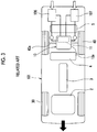
oil coolers electric vehicle 101 illustrated inFIG. 3 , the twooil coolers - In the electric vehicle 1 according to the embodiment, however, one of the oil coolers is disposed at a position that is likely to be exposed to a collision load earlier than the other one during a vehicle rear collision. Accordingly, the impact on the other oil cooler can be alleviated and at least the other oil cooler is capable of surviving the collision. Specifically, the first oil cooler 6 of the electric vehicle 1 according to the embodiment is disposed at a position offset in the vehicle front-rear direction with respect to the second oil cooler 7 as illustrated in
FIG. 1 . More specifically, the first and second oil coolers 6, 7 are disposed such that the end face (rear end) of the first oil cooler 6 that is on the rear side of the vehicle is behind the end face (rear end) of the second oil cooler 7 that is on the rear side of the vehicle (refer to the dashed line inFIG. 1 ). - Since the first oil cooler 6 and the second oil cooler 7 are disposed at the positions that are offset in the vehicle front-rear direction as described above, the first oil cooler 6, which is one of the first and second oil coolers 6, 7 that has a relatively rearward disposition, is exposed to the collision load earlier than the second oil cooler 7 during the vehicle rear collision. Accordingly, the first oil cooler 6 itself is likely to be broken during the collision. Nevertheless, since the first oil cooler 6 receives the collision load earlier than the second oil cooler 7, the impact on the second oil cooler 7, which has a relatively forward disposition, is alleviated unlike in the case where the two
oil coolers - As described above, the first and second oil coolers 6, 7 are connected to the
transaxle case 10a via theseparate oil passages transaxle case 10a. Accordingly, the unbroken second oil cooler 7 is capable of avoiding effects of the breakage of the first oil cooler 6, thefirst oil passage 6a, and thefirst pump 8. As a result, the cooling oil supply from the second oil cooler 7 to thetransaxle case 10a via thesecond oil passage 7a continues to be performed even when the first oil cooler 6, thefirst oil passage 6a, and thefirst pump 8 are broken during the vehicle rear collision, and thus the electric motor 11 can be cooled in a more reliable way. - The invention is not limited to the embodiment described above and can take various forms without departing from its spirit or key features.
- In the embodiment described above, the first oil cooler 6 disposed on the right side in the vehicle width direction is disposed at the position offset with respect to and behind the second oil cooler 7 disposed on the left side in the vehicle width direction. However, the invention is not limited thereto. For example, the first oil cooler 6 disposed on the right side in the vehicle width direction may be disposed at a position offset with respect to and ahead of the second oil cooler 7 disposed on the left side in the vehicle width direction.
- As described above, the embodiment is merely an example in every respect and the embodiment should not be interpreted restrictively. In addition, any modification or change belonging to a scope equivalent to the scope of claims is within the scope of the invention.
- With the invention, a total loss of oil coolers can be suppressed during a vehicle rear collision. Accordingly, the invention can be applied in a highly beneficial way to an electric vehicle in which a driving device is disposed in a rear portion of the electric vehicle such that a rear wheel axle crosses the driving device in which an electric motor and a mechanism transmitting a driving force from the electric motor to the rear wheel axle are accommodated in a case.
Claims (4)
- An electric vehicle (1) comprising:a driving device (10) including an electric motor (11) and a mechanism transmitting a driving force from the electric motor (11) to a rear wheel axle (40a), the electric motor (11) and the mechanism being accommodated in a case (10a), and the driving device (10) being disposed in a rear portion of the vehicle such that the driving device (10) crosses the rear wheel axle (40a);a first oil cooler (6) configured to cool oil in the case (10a), the first oil cooler (6) being disposed behind the rear wheel axle (40a); anda second oil cooler (7) configured to cool the oil in the case (10a), the second oil cooler (7) being disposed behind the rear wheel axle (40a) and disposed at a position offset in a vehicle front-rear direction with respect to the first oil cooler (6),
- The electric vehicle (1) according to claim 1, wherein the first oil cooler (6) and the second oil cooler (7) are disposed such that an end face of the first oil cooler (6) which faces toward a rear side of the vehicle is positioned offset in the vehicle front-rear direction with respect to an end face of the second oil cooler (7) which faces toward the rear side of the vehicle.
- The electric vehicle (1) according to claim 1 or 2, further comprising:a first oil passage (6a) connecting the first oil cooler (6) and the case (10a); anda second oil passage (7a) connecting the second oil cooler (7) and the case (10a), and the second oil passage (7a) being different from the first oil passage (6a).
- The electric vehicle (1) according to claim 3, further comprising:a first pump (8) configured to supply the oil from the first oil cooler (6) to the electric motor (11) accommodated in the case (10a), the first pump (8) being disposed on the first oil passage (6a); anda second pump (9) configured to supply the oil from the second oil cooler (7) to the electric motor (11) accommodated in the case (10a), the second pump (9) being disposed on the second oil passage (7a).
Applications Claiming Priority (1)
| Application Number | Priority Date | Filing Date | Title |
|---|---|---|---|
| JP2016212853A JP6436146B2 (en) | 2016-10-31 | 2016-10-31 | Electric vehicle |
Publications (2)
| Publication Number | Publication Date |
|---|---|
| EP3323657A1 true EP3323657A1 (en) | 2018-05-23 |
| EP3323657B1 EP3323657B1 (en) | 2020-02-12 |
Family
ID=60119915
Family Applications (1)
| Application Number | Title | Priority Date | Filing Date |
|---|---|---|---|
| EP17196696.3A Active EP3323657B1 (en) | 2016-10-31 | 2017-10-16 | Electric vehicle |
Country Status (4)
| Country | Link |
|---|---|
| US (1) | US10100711B2 (en) |
| EP (1) | EP3323657B1 (en) |
| JP (1) | JP6436146B2 (en) |
| CN (1) | CN108016266B (en) |
Cited By (1)
| Publication number | Priority date | Publication date | Assignee | Title |
|---|---|---|---|---|
| DE102022107957A1 (en) | 2022-04-04 | 2023-10-05 | Dr. Ing. H.C. F. Porsche Aktiengesellschaft | Motor vehicle and method for cooling the same |
Families Citing this family (5)
| Publication number | Priority date | Publication date | Assignee | Title |
|---|---|---|---|---|
| JP6597653B2 (en) * | 2017-01-19 | 2019-10-30 | トヨタ自動車株式会社 | Fuel cell vehicle |
| CN112776580A (en) * | 2017-09-20 | 2021-05-11 | 丰田自动车株式会社 | Electric vehicle |
| JP7285684B2 (en) * | 2019-05-07 | 2023-06-02 | ダイハツ工業株式会社 | Power unit suspension structure |
| CN110154750A (en) * | 2019-05-27 | 2019-08-23 | 重庆大学 | A kind of transmission system of bi-motor four-drive electric car |
| JP2025040480A (en) * | 2023-09-12 | 2025-03-25 | 三菱電機モビリティ株式会社 | Electric vehicle drive unit |
Citations (4)
| Publication number | Priority date | Publication date | Assignee | Title |
|---|---|---|---|---|
| US20080135209A1 (en) * | 2006-12-11 | 2008-06-12 | Deere & Company | Stacked Heat Exchanger System with Swing-Out Heat Exchangers |
| US20140202669A1 (en) * | 2013-01-21 | 2014-07-24 | Denso International America, Inc. | Dual radiator engine cooling module - single coolant loop |
| EP3009288A1 (en) * | 2013-08-08 | 2016-04-20 | Komatsu Ltd. | Wheel loader |
| JP2016121733A (en) | 2014-12-24 | 2016-07-07 | アイシン精機株式会社 | Lubricating structure for vehicle drive device |
Family Cites Families (19)
| Publication number | Priority date | Publication date | Assignee | Title |
|---|---|---|---|---|
| US4479404A (en) * | 1981-09-08 | 1984-10-30 | Stockton Thomas R | Concentric powertrain for electric vehicle |
| JP3423410B2 (en) * | 1994-05-16 | 2003-07-07 | アイシン・エィ・ダブリュ株式会社 | Transmission control device for automatic transmission |
| US6394210B2 (en) * | 1999-06-07 | 2002-05-28 | Mitsubishi Heavy Industries, Ltd. | Temperature controller for vehicular battery |
| US6860358B1 (en) * | 2002-10-04 | 2005-03-01 | Hydro-Gear Limited Partnership | Utility vehicle having hydrostatic drive |
| EP1630030A3 (en) * | 2004-08-24 | 2008-04-09 | Kanzaki Kokyukoki MFG. Co., Ltd. | Pump system and axle-driving system |
| JP2009132252A (en) * | 2007-11-29 | 2009-06-18 | Toyota Motor Corp | In-wheel motor for vehicles |
| JP4831078B2 (en) * | 2008-01-16 | 2011-12-07 | トヨタ自動車株式会社 | Power transmission device |
| CN201202522Y (en) * | 2008-04-01 | 2009-03-04 | 广州大华德盛科技有限公司 | An electronically controlled hydraulically driven fan heating system for a bus |
| US8701806B2 (en) * | 2009-03-18 | 2014-04-22 | Kanzaki Kokyukoki Mfg. Co., Ltd. | Electric transaxle unit |
| JP5250497B2 (en) * | 2009-07-29 | 2013-07-31 | 日立建機株式会社 | Dust-proof net layout |
| US8371978B2 (en) * | 2010-03-31 | 2013-02-12 | Aisin Aw Co., Ltd. | Vehicle transmission |
| FR2958581B1 (en) * | 2010-04-07 | 2012-04-27 | Renault Sa | COOLING DEVICE FOR MOTOR VEHICLE |
| JP5760215B2 (en) * | 2011-01-24 | 2015-08-05 | 株式会社 神崎高級工機製作所 | Axle drive device for work vehicle |
| JP5817247B2 (en) * | 2011-06-24 | 2015-11-18 | 株式会社ジェイテクト | Motor rotational force transmission device |
| JP5655952B2 (en) * | 2011-10-12 | 2015-01-21 | トヨタ自動車株式会社 | Vehicle front structure |
| JP5912705B2 (en) * | 2012-03-16 | 2016-04-27 | トヨタ自動車株式会社 | Vehicle control system |
| JP5738240B2 (en) * | 2012-07-24 | 2015-06-17 | アイシン精機株式会社 | Reducer lubrication structure |
| CN104494408B (en) * | 2014-12-15 | 2017-11-07 | 东风汽车公司 | A kind of pure electric mini-car chassis arrangement |
| JP2016182879A (en) * | 2015-03-26 | 2016-10-20 | Ntn株式会社 | Vehicle drive device |
-
2016
- 2016-10-31 JP JP2016212853A patent/JP6436146B2/en active Active
-
2017
- 2017-10-10 US US15/729,246 patent/US10100711B2/en active Active
- 2017-10-16 EP EP17196696.3A patent/EP3323657B1/en active Active
- 2017-10-26 CN CN201711013265.5A patent/CN108016266B/en not_active Expired - Fee Related
Patent Citations (4)
| Publication number | Priority date | Publication date | Assignee | Title |
|---|---|---|---|---|
| US20080135209A1 (en) * | 2006-12-11 | 2008-06-12 | Deere & Company | Stacked Heat Exchanger System with Swing-Out Heat Exchangers |
| US20140202669A1 (en) * | 2013-01-21 | 2014-07-24 | Denso International America, Inc. | Dual radiator engine cooling module - single coolant loop |
| EP3009288A1 (en) * | 2013-08-08 | 2016-04-20 | Komatsu Ltd. | Wheel loader |
| JP2016121733A (en) | 2014-12-24 | 2016-07-07 | アイシン精機株式会社 | Lubricating structure for vehicle drive device |
Cited By (2)
| Publication number | Priority date | Publication date | Assignee | Title |
|---|---|---|---|---|
| DE102022107957A1 (en) | 2022-04-04 | 2023-10-05 | Dr. Ing. H.C. F. Porsche Aktiengesellschaft | Motor vehicle and method for cooling the same |
| DE102022107957B4 (en) | 2022-04-04 | 2024-08-08 | Dr. Ing. H.C. F. Porsche Aktiengesellschaft | Motor vehicle and method for cooling such a vehicle |
Also Published As
| Publication number | Publication date |
|---|---|
| JP2018069957A (en) | 2018-05-10 |
| CN108016266B (en) | 2020-10-30 |
| US10100711B2 (en) | 2018-10-16 |
| US20180119598A1 (en) | 2018-05-03 |
| EP3323657B1 (en) | 2020-02-12 |
| JP6436146B2 (en) | 2018-12-12 |
| CN108016266A (en) | 2018-05-11 |
Similar Documents
| Publication | Publication Date | Title |
|---|---|---|
| EP3323657B1 (en) | Electric vehicle | |
| US20130248264A1 (en) | Vehicle | |
| CN104334386B (en) | Motor vehicle driven by mixed power | |
| US20210001713A1 (en) | Drive unit and vehicle | |
| US10569646B2 (en) | Fuel cell vehicle | |
| CN108177514A (en) | A kind of integrated form power drive used for electric vehicle and control system | |
| WO2010095610A1 (en) | Hybrid electric vehicle | |
| CN102328576B (en) | Driving apparatus for hybrid vehicle | |
| US7514805B2 (en) | Drive axle having an electrical converter | |
| US12576731B2 (en) | Fuel cell electric vehicle | |
| JP2018131043A (en) | Fuel cell vehicle | |
| US20240123821A1 (en) | Powertrain system and electric vehicle | |
| US7650958B2 (en) | Traction drive having an electrical converter | |
| US11772478B2 (en) | Vehicle | |
| JP2020059299A (en) | Fuel cell freight car | |
| JP2020019452A (en) | Electric vehicle | |
| JP7728296B2 (en) | Power control unit mounting structure for motor unit | |
| JP2013056599A (en) | Electric vehicle | |
| US20260061861A1 (en) | Protective structure for high-voltage module | |
| JP2018122606A (en) | Fuel cell vehicle | |
| EP4592116A1 (en) | Electrified vehicle | |
| US12533948B2 (en) | Power transmission device and drive device | |
| US20250007070A1 (en) | Vehicle and power battery pack thereof | |
| WO2023210540A1 (en) | Electric vehicle | |
| JP6708141B2 (en) | Fuel cell vehicle |
Legal Events
| Date | Code | Title | Description |
|---|---|---|---|
| PUAI | Public reference made under article 153(3) epc to a published international application that has entered the european phase |
Free format text: ORIGINAL CODE: 0009012 |
|
| STAA | Information on the status of an ep patent application or granted ep patent |
Free format text: STATUS: REQUEST FOR EXAMINATION WAS MADE |
|
| 17P | Request for examination filed |
Effective date: 20171016 |
|
| AK | Designated contracting states |
Kind code of ref document: A1 Designated state(s): AL AT BE BG CH CY CZ DE DK EE ES FI FR GB GR HR HU IE IS IT LI LT LU LV MC MK MT NL NO PL PT RO RS SE SI SK SM TR |
|
| AX | Request for extension of the european patent |
Extension state: BA ME |
|
| GRAP | Despatch of communication of intention to grant a patent |
Free format text: ORIGINAL CODE: EPIDOSNIGR1 |
|
| STAA | Information on the status of an ep patent application or granted ep patent |
Free format text: STATUS: GRANT OF PATENT IS INTENDED |
|
| INTG | Intention to grant announced |
Effective date: 20190902 |
|
| GRAS | Grant fee paid |
Free format text: ORIGINAL CODE: EPIDOSNIGR3 |
|
| GRAA | (expected) grant |
Free format text: ORIGINAL CODE: 0009210 |
|
| STAA | Information on the status of an ep patent application or granted ep patent |
Free format text: STATUS: THE PATENT HAS BEEN GRANTED |
|
| AK | Designated contracting states |
Kind code of ref document: B1 Designated state(s): AL AT BE BG CH CY CZ DE DK EE ES FI FR GB GR HR HU IE IS IT LI LT LU LV MC MK MT NL NO PL PT RO RS SE SI SK SM TR |
|
| REG | Reference to a national code |
Ref country code: GB Ref legal event code: FG4D |
|
| REG | Reference to a national code |
Ref country code: CH Ref legal event code: EP |
|
| REG | Reference to a national code |
Ref country code: AT Ref legal event code: REF Ref document number: 1231647 Country of ref document: AT Kind code of ref document: T Effective date: 20200215 |
|
| REG | Reference to a national code |
Ref country code: IE Ref legal event code: FG4D |
|
| REG | Reference to a national code |
Ref country code: DE Ref legal event code: R096 Ref document number: 602017011558 Country of ref document: DE |
|
| PG25 | Lapsed in a contracting state [announced via postgrant information from national office to epo] |
Ref country code: RS Free format text: LAPSE BECAUSE OF FAILURE TO SUBMIT A TRANSLATION OF THE DESCRIPTION OR TO PAY THE FEE WITHIN THE PRESCRIBED TIME-LIMIT Effective date: 20200212 Ref country code: NO Free format text: LAPSE BECAUSE OF FAILURE TO SUBMIT A TRANSLATION OF THE DESCRIPTION OR TO PAY THE FEE WITHIN THE PRESCRIBED TIME-LIMIT Effective date: 20200512 Ref country code: FI Free format text: LAPSE BECAUSE OF FAILURE TO SUBMIT A TRANSLATION OF THE DESCRIPTION OR TO PAY THE FEE WITHIN THE PRESCRIBED TIME-LIMIT Effective date: 20200212 |
|
| REG | Reference to a national code |
Ref country code: LT Ref legal event code: MG4D |
|
| REG | Reference to a national code |
Ref country code: NL Ref legal event code: MP Effective date: 20200212 |
|
| PG25 | Lapsed in a contracting state [announced via postgrant information from national office to epo] |
Ref country code: SE Free format text: LAPSE BECAUSE OF FAILURE TO SUBMIT A TRANSLATION OF THE DESCRIPTION OR TO PAY THE FEE WITHIN THE PRESCRIBED TIME-LIMIT Effective date: 20200212 Ref country code: LV Free format text: LAPSE BECAUSE OF FAILURE TO SUBMIT A TRANSLATION OF THE DESCRIPTION OR TO PAY THE FEE WITHIN THE PRESCRIBED TIME-LIMIT Effective date: 20200212 Ref country code: HR Free format text: LAPSE BECAUSE OF FAILURE TO SUBMIT A TRANSLATION OF THE DESCRIPTION OR TO PAY THE FEE WITHIN THE PRESCRIBED TIME-LIMIT Effective date: 20200212 Ref country code: IS Free format text: LAPSE BECAUSE OF FAILURE TO SUBMIT A TRANSLATION OF THE DESCRIPTION OR TO PAY THE FEE WITHIN THE PRESCRIBED TIME-LIMIT Effective date: 20200612 Ref country code: GR Free format text: LAPSE BECAUSE OF FAILURE TO SUBMIT A TRANSLATION OF THE DESCRIPTION OR TO PAY THE FEE WITHIN THE PRESCRIBED TIME-LIMIT Effective date: 20200513 Ref country code: BG Free format text: LAPSE BECAUSE OF FAILURE TO SUBMIT A TRANSLATION OF THE DESCRIPTION OR TO PAY THE FEE WITHIN THE PRESCRIBED TIME-LIMIT Effective date: 20200512 |
|
| PG25 | Lapsed in a contracting state [announced via postgrant information from national office to epo] |
Ref country code: NL Free format text: LAPSE BECAUSE OF FAILURE TO SUBMIT A TRANSLATION OF THE DESCRIPTION OR TO PAY THE FEE WITHIN THE PRESCRIBED TIME-LIMIT Effective date: 20200212 |
|
| PG25 | Lapsed in a contracting state [announced via postgrant information from national office to epo] |
Ref country code: RO Free format text: LAPSE BECAUSE OF FAILURE TO SUBMIT A TRANSLATION OF THE DESCRIPTION OR TO PAY THE FEE WITHIN THE PRESCRIBED TIME-LIMIT Effective date: 20200212 Ref country code: SK Free format text: LAPSE BECAUSE OF FAILURE TO SUBMIT A TRANSLATION OF THE DESCRIPTION OR TO PAY THE FEE WITHIN THE PRESCRIBED TIME-LIMIT Effective date: 20200212 Ref country code: CZ Free format text: LAPSE BECAUSE OF FAILURE TO SUBMIT A TRANSLATION OF THE DESCRIPTION OR TO PAY THE FEE WITHIN THE PRESCRIBED TIME-LIMIT Effective date: 20200212 Ref country code: SM Free format text: LAPSE BECAUSE OF FAILURE TO SUBMIT A TRANSLATION OF THE DESCRIPTION OR TO PAY THE FEE WITHIN THE PRESCRIBED TIME-LIMIT Effective date: 20200212 Ref country code: EE Free format text: LAPSE BECAUSE OF FAILURE TO SUBMIT A TRANSLATION OF THE DESCRIPTION OR TO PAY THE FEE WITHIN THE PRESCRIBED TIME-LIMIT Effective date: 20200212 Ref country code: PT Free format text: LAPSE BECAUSE OF FAILURE TO SUBMIT A TRANSLATION OF THE DESCRIPTION OR TO PAY THE FEE WITHIN THE PRESCRIBED TIME-LIMIT Effective date: 20200705 Ref country code: DK Free format text: LAPSE BECAUSE OF FAILURE TO SUBMIT A TRANSLATION OF THE DESCRIPTION OR TO PAY THE FEE WITHIN THE PRESCRIBED TIME-LIMIT Effective date: 20200212 Ref country code: ES Free format text: LAPSE BECAUSE OF FAILURE TO SUBMIT A TRANSLATION OF THE DESCRIPTION OR TO PAY THE FEE WITHIN THE PRESCRIBED TIME-LIMIT Effective date: 20200212 Ref country code: LT Free format text: LAPSE BECAUSE OF FAILURE TO SUBMIT A TRANSLATION OF THE DESCRIPTION OR TO PAY THE FEE WITHIN THE PRESCRIBED TIME-LIMIT Effective date: 20200212 |
|
| REG | Reference to a national code |
Ref country code: DE Ref legal event code: R097 Ref document number: 602017011558 Country of ref document: DE |
|
| REG | Reference to a national code |
Ref country code: AT Ref legal event code: MK05 Ref document number: 1231647 Country of ref document: AT Kind code of ref document: T Effective date: 20200212 |
|
| PLBE | No opposition filed within time limit |
Free format text: ORIGINAL CODE: 0009261 |
|
| STAA | Information on the status of an ep patent application or granted ep patent |
Free format text: STATUS: NO OPPOSITION FILED WITHIN TIME LIMIT |
|
| 26N | No opposition filed |
Effective date: 20201113 |
|
| PG25 | Lapsed in a contracting state [announced via postgrant information from national office to epo] |
Ref country code: AT Free format text: LAPSE BECAUSE OF FAILURE TO SUBMIT A TRANSLATION OF THE DESCRIPTION OR TO PAY THE FEE WITHIN THE PRESCRIBED TIME-LIMIT Effective date: 20200212 Ref country code: IT Free format text: LAPSE BECAUSE OF FAILURE TO SUBMIT A TRANSLATION OF THE DESCRIPTION OR TO PAY THE FEE WITHIN THE PRESCRIBED TIME-LIMIT Effective date: 20200212 |
|
| PG25 | Lapsed in a contracting state [announced via postgrant information from national office to epo] |
Ref country code: PL Free format text: LAPSE BECAUSE OF FAILURE TO SUBMIT A TRANSLATION OF THE DESCRIPTION OR TO PAY THE FEE WITHIN THE PRESCRIBED TIME-LIMIT Effective date: 20200212 Ref country code: SI Free format text: LAPSE BECAUSE OF FAILURE TO SUBMIT A TRANSLATION OF THE DESCRIPTION OR TO PAY THE FEE WITHIN THE PRESCRIBED TIME-LIMIT Effective date: 20200212 |
|
| REG | Reference to a national code |
Ref country code: CH Ref legal event code: PL |
|
| PG25 | Lapsed in a contracting state [announced via postgrant information from national office to epo] |
Ref country code: MC Free format text: LAPSE BECAUSE OF FAILURE TO SUBMIT A TRANSLATION OF THE DESCRIPTION OR TO PAY THE FEE WITHIN THE PRESCRIBED TIME-LIMIT Effective date: 20200212 Ref country code: LU Free format text: LAPSE BECAUSE OF NON-PAYMENT OF DUE FEES Effective date: 20201016 |
|
| REG | Reference to a national code |
Ref country code: BE Ref legal event code: MM Effective date: 20201031 |
|
| PG25 | Lapsed in a contracting state [announced via postgrant information from national office to epo] |
Ref country code: LI Free format text: LAPSE BECAUSE OF NON-PAYMENT OF DUE FEES Effective date: 20201031 Ref country code: CH Free format text: LAPSE BECAUSE OF NON-PAYMENT OF DUE FEES Effective date: 20201031 Ref country code: BE Free format text: LAPSE BECAUSE OF NON-PAYMENT OF DUE FEES Effective date: 20201031 |
|
| PG25 | Lapsed in a contracting state [announced via postgrant information from national office to epo] |
Ref country code: IE Free format text: LAPSE BECAUSE OF NON-PAYMENT OF DUE FEES Effective date: 20201016 |
|
| REG | Reference to a national code |
Ref country code: DE Ref legal event code: R084 Ref document number: 602017011558 Country of ref document: DE |
|
| PG25 | Lapsed in a contracting state [announced via postgrant information from national office to epo] |
Ref country code: TR Free format text: LAPSE BECAUSE OF FAILURE TO SUBMIT A TRANSLATION OF THE DESCRIPTION OR TO PAY THE FEE WITHIN THE PRESCRIBED TIME-LIMIT Effective date: 20200212 Ref country code: MT Free format text: LAPSE BECAUSE OF FAILURE TO SUBMIT A TRANSLATION OF THE DESCRIPTION OR TO PAY THE FEE WITHIN THE PRESCRIBED TIME-LIMIT Effective date: 20200212 Ref country code: CY Free format text: LAPSE BECAUSE OF FAILURE TO SUBMIT A TRANSLATION OF THE DESCRIPTION OR TO PAY THE FEE WITHIN THE PRESCRIBED TIME-LIMIT Effective date: 20200212 |
|
| REG | Reference to a national code |
Ref country code: GB Ref legal event code: 746 Effective date: 20220509 |
|
| PG25 | Lapsed in a contracting state [announced via postgrant information from national office to epo] |
Ref country code: MK Free format text: LAPSE BECAUSE OF FAILURE TO SUBMIT A TRANSLATION OF THE DESCRIPTION OR TO PAY THE FEE WITHIN THE PRESCRIBED TIME-LIMIT Effective date: 20200212 Ref country code: AL Free format text: LAPSE BECAUSE OF FAILURE TO SUBMIT A TRANSLATION OF THE DESCRIPTION OR TO PAY THE FEE WITHIN THE PRESCRIBED TIME-LIMIT Effective date: 20200212 |
|
| P01 | Opt-out of the competence of the unified patent court (upc) registered |
Effective date: 20230427 |
|
| PGFP | Annual fee paid to national office [announced via postgrant information from national office to epo] |
Ref country code: GB Payment date: 20250828 Year of fee payment: 9 |
|
| PGFP | Annual fee paid to national office [announced via postgrant information from national office to epo] |
Ref country code: FR Payment date: 20250908 Year of fee payment: 9 |
|
| PGFP | Annual fee paid to national office [announced via postgrant information from national office to epo] |
Ref country code: DE Payment date: 20250902 Year of fee payment: 9 |