EP3323587B1 - A bottle blowing machine - Google Patents
A bottle blowing machine Download PDFInfo
- Publication number
- EP3323587B1 EP3323587B1 EP17205968.5A EP17205968A EP3323587B1 EP 3323587 B1 EP3323587 B1 EP 3323587B1 EP 17205968 A EP17205968 A EP 17205968A EP 3323587 B1 EP3323587 B1 EP 3323587B1
- Authority
- EP
- European Patent Office
- Prior art keywords
- mould
- rotation
- swing
- mould plate
- machine frame
- Prior art date
- Legal status (The legal status is an assumption and is not a legal conclusion. Google has not performed a legal analysis and makes no representation as to the accuracy of the status listed.)
- Active
Links
Images


Classifications
-
- B—PERFORMING OPERATIONS; TRANSPORTING
- B29—WORKING OF PLASTICS; WORKING OF SUBSTANCES IN A PLASTIC STATE IN GENERAL
- B29C—SHAPING OR JOINING OF PLASTICS; SHAPING OF MATERIAL IN A PLASTIC STATE, NOT OTHERWISE PROVIDED FOR; AFTER-TREATMENT OF THE SHAPED PRODUCTS, e.g. REPAIRING
- B29C49/00—Blow-moulding, i.e. blowing a preform or parison to a desired shape within a mould; Apparatus therefor
- B29C49/42—Component parts, details or accessories; Auxiliary operations
- B29C49/56—Opening, closing or clamping means
-
- B—PERFORMING OPERATIONS; TRANSPORTING
- B29—WORKING OF PLASTICS; WORKING OF SUBSTANCES IN A PLASTIC STATE IN GENERAL
- B29C—SHAPING OR JOINING OF PLASTICS; SHAPING OF MATERIAL IN A PLASTIC STATE, NOT OTHERWISE PROVIDED FOR; AFTER-TREATMENT OF THE SHAPED PRODUCTS, e.g. REPAIRING
- B29C33/00—Moulds or cores; Details thereof or accessories therefor
- B29C33/20—Opening, closing or clamping
-
- B—PERFORMING OPERATIONS; TRANSPORTING
- B29—WORKING OF PLASTICS; WORKING OF SUBSTANCES IN A PLASTIC STATE IN GENERAL
- B29C—SHAPING OR JOINING OF PLASTICS; SHAPING OF MATERIAL IN A PLASTIC STATE, NOT OTHERWISE PROVIDED FOR; AFTER-TREATMENT OF THE SHAPED PRODUCTS, e.g. REPAIRING
- B29C49/00—Blow-moulding, i.e. blowing a preform or parison to a desired shape within a mould; Apparatus therefor
- B29C49/42—Component parts, details or accessories; Auxiliary operations
- B29C49/48—Moulds
- B29C2049/4879—Moulds characterised by mould configurations
- B29C2049/4892—Mould halves consisting of an independent main and bottom part
-
- B—PERFORMING OPERATIONS; TRANSPORTING
- B29—WORKING OF PLASTICS; WORKING OF SUBSTANCES IN A PLASTIC STATE IN GENERAL
- B29C—SHAPING OR JOINING OF PLASTICS; SHAPING OF MATERIAL IN A PLASTIC STATE, NOT OTHERWISE PROVIDED FOR; AFTER-TREATMENT OF THE SHAPED PRODUCTS, e.g. REPAIRING
- B29C49/00—Blow-moulding, i.e. blowing a preform or parison to a desired shape within a mould; Apparatus therefor
- B29C49/42—Component parts, details or accessories; Auxiliary operations
- B29C49/56—Opening, closing or clamping means
- B29C2049/566—Locking means
- B29C2049/5661—Mechanical
- B29C2049/5664—Translating locking pin
-
- B—PERFORMING OPERATIONS; TRANSPORTING
- B29—WORKING OF PLASTICS; WORKING OF SUBSTANCES IN A PLASTIC STATE IN GENERAL
- B29C—SHAPING OR JOINING OF PLASTICS; SHAPING OF MATERIAL IN A PLASTIC STATE, NOT OTHERWISE PROVIDED FOR; AFTER-TREATMENT OF THE SHAPED PRODUCTS, e.g. REPAIRING
- B29C33/00—Moulds or cores; Details thereof or accessories therefor
- B29C33/20—Opening, closing or clamping
- B29C33/26—Opening, closing or clamping by pivotal movement
-
- B—PERFORMING OPERATIONS; TRANSPORTING
- B29—WORKING OF PLASTICS; WORKING OF SUBSTANCES IN A PLASTIC STATE IN GENERAL
- B29C—SHAPING OR JOINING OF PLASTICS; SHAPING OF MATERIAL IN A PLASTIC STATE, NOT OTHERWISE PROVIDED FOR; AFTER-TREATMENT OF THE SHAPED PRODUCTS, e.g. REPAIRING
- B29C49/00—Blow-moulding, i.e. blowing a preform or parison to a desired shape within a mould; Apparatus therefor
- B29C49/28—Blow-moulding apparatus
- B29C49/30—Blow-moulding apparatus having movable moulds or mould parts
- B29C49/36—Blow-moulding apparatus having movable moulds or mould parts rotatable about one axis
-
- B—PERFORMING OPERATIONS; TRANSPORTING
- B29—WORKING OF PLASTICS; WORKING OF SUBSTANCES IN A PLASTIC STATE IN GENERAL
- B29C—SHAPING OR JOINING OF PLASTICS; SHAPING OF MATERIAL IN A PLASTIC STATE, NOT OTHERWISE PROVIDED FOR; AFTER-TREATMENT OF THE SHAPED PRODUCTS, e.g. REPAIRING
- B29C49/00—Blow-moulding, i.e. blowing a preform or parison to a desired shape within a mould; Apparatus therefor
- B29C49/42—Component parts, details or accessories; Auxiliary operations
- B29C49/56—Opening, closing or clamping means
- B29C49/5601—Mechanically operated, i.e. closing or opening of the mould parts is done by mechanic means
- B29C49/5602—Mechanically operated, i.e. closing or opening of the mould parts is done by mechanic means using cams
-
- B—PERFORMING OPERATIONS; TRANSPORTING
- B29—WORKING OF PLASTICS; WORKING OF SUBSTANCES IN A PLASTIC STATE IN GENERAL
- B29C—SHAPING OR JOINING OF PLASTICS; SHAPING OF MATERIAL IN A PLASTIC STATE, NOT OTHERWISE PROVIDED FOR; AFTER-TREATMENT OF THE SHAPED PRODUCTS, e.g. REPAIRING
- B29C49/00—Blow-moulding, i.e. blowing a preform or parison to a desired shape within a mould; Apparatus therefor
- B29C49/42—Component parts, details or accessories; Auxiliary operations
- B29C49/56—Opening, closing or clamping means
- B29C49/5608—Asymmetric movement of mould parts, e.g. by moving only one mould part
-
- B—PERFORMING OPERATIONS; TRANSPORTING
- B29—WORKING OF PLASTICS; WORKING OF SUBSTANCES IN A PLASTIC STATE IN GENERAL
- B29C—SHAPING OR JOINING OF PLASTICS; SHAPING OF MATERIAL IN A PLASTIC STATE, NOT OTHERWISE PROVIDED FOR; AFTER-TREATMENT OF THE SHAPED PRODUCTS, e.g. REPAIRING
- B29C49/00—Blow-moulding, i.e. blowing a preform or parison to a desired shape within a mould; Apparatus therefor
- B29C49/42—Component parts, details or accessories; Auxiliary operations
- B29C49/56—Opening, closing or clamping means
- B29C49/5613—Opening, closing or clamping means characterised by connected mould part movement, e.g. bottom part movement is linked to mould half movement
Definitions
- the present invention relates to the field of processing equipment of a beverage bottle, and more particularly to a bottle blowing machine.
- a bottle blowing machine comprises a mould opening and closing mechanism and a bottom mould positioning mechanism.
- a conventional mould opening and closing mechanism comprises a machine frame, a fixed mould plate and a moving mould plate which are mounted on the machine frame.
- a mould locking mechanism is provided at the joint of the fixed mould plate and the moving mould plate.
- the moving mould plate is L-shaped and driven by a mould opening and closing air cylinder.
- the mould opening and closing air cylinder drives a spline, and the spline drives a moving mould plate gear mounted on a gear shaft, and the gear shaft is connected with the moving mould plate and mounted on a support frame.
- a conventional bottom mould positioning mechanism for example, a bottom mould locking mechanism of a linear bottle blowing machine as disclosed in patent publication No. CN201755911U , comprises a mould mounting plate, a bottle mould, a bottom mould, an actuating mechansim, a positioning mechanism and a supporting seat.
- the end of the cavity of the bottle mould is sleeved with the bottom mould which is connected with the actuating mechanism.
- the positioning mechanism is horizontally disposed on the support seat and comprises a positioning block air cylinder and a positioning block connected with each other.
- the actuating mechanism comprises a bottom mould mounting plate and a bottom mould elevating air cylinder. An upper surface of the bottom mould mounting plate is connected with the bottom mould, and a lower surface of the bottom mould mounting plate is connected with the bottom mould elevating air cylinder which is mounted on a support frame.
- the mould opening and closing mechanism and the bottom mould positioning mechanism are complicated in configuration and bulky, and each mechanism is self-driven, thereby leading to the inconvenience of operation and high cost.
- US 2012/177771 A1 relates to a device for blow-molding containers, the device comprising a structure and a platform mounted to rotate on the structure about an axis of rotation, the platform being provided with blower members and with molds that are mounted under the blower members, each of which comprises a stationary mold portion and a movable mold portion that is movable by control means between an open position and a closed position for the mold, wherein the device includes blocking members for blocking the molds in the closed state, each blocking member comprising a strut mounted on the platform to move between a retracted position and a blocking position.
- DE202004017530U1 relates to a tool clamp for a blow molding machine, wherein, when a moving tool frame(402) and a fixed tool frame(401) are closed against each other they form a chamber surrounding a movable tool halves(501,502), contact surfaces(7) between the closed tool frames and tool halves are arc-shaped, the chamber is round to accommodate the moving(502) and fixed tool halves, positioning blocks(8) cranked outwards from the tool halves engage in corresponding holes(9) in the moving frame(402) and fixed frame(401), ring-shaped securing blocks(10) screwed onto the tool frames hold the positioning blocks in their respective holes.
- An object of the invention is to provide an improved linkage of mould opening and closing and bottom mould positioning.
- a bottle blowing machine comprising
- a through-hole is opened on each of the rotation member and the moving mould plate for the rotation shaft extending through the rotation member and the moving mould plate from bottom to top.
- a swing arm is connected on a lower end of the rotation shaft, and a power source drives the rotation of the rotation shaft by the swing arm.
- the plurality of sliding blocks comprises a first sliding block and a second sliding block located at two opposite sides of the bottom mould.
- the bottom mould positioning assembly also comprises a first guide rail and a second guide rail fixedly disposed on the machine frame, the first sliding block is slidably disposed on the first guide rail, and the second sliding block is slidably disposed on the second guide rail.
- the bilateral positioning of the bottom mould is achieved by means of the two sliding blocks.
- the multiple swing members comprise a first swing member and a second swing member which respectively are rotatably connected with the machine frame.
- the first swing member and the second swing member respectively and correspondingly drive the sliding of the first sliding block and the second sliding block.
- the sliding of the two sliding blocks are controlled separately by the swinging of the two swing members, this will simplify controlling means.
- a first sliding groove is opened on the first swing member at a distance from the connecting position of the first swing member with the machine frame
- a second sliding groove is opened on the second swing member at a distance from the connecting position of the second swing member with the machine frame
- a first projection and a second projection respectively are formed on an upper surface of the first sliding block and the second sliding block
- the first projection is slidably inserted into the first sliding groove
- the second projection is slidably inserted into the second sliding groove.
- the rotation member has a first guiding surface and a second guiding surface on its' side surface, a first protrusion protruding towards the rotation member is formed on the first swing member, a second protrusion protruding towards the rotation member is formed on the second swing member.
- the first guiding surface slidably contacts with the first protrusion
- the second guiding surface slidably contacts with the second protrusion
- the distance between the contact position of the first guiding surface with the first protrusion and the axis of rotation of the rotation member and the distance between the contact position of the second guiding surface with the second protrusion and the axis of rotation of the rotation member respectively change with the rotation of the rotation member.
- This change in distance will produce a guiding effect such that the protrusions will move and the two swing members swing correspondingly.
- an elastic member is arranged between each of the swing members and the machine frame for providing a restoring force for the swing members.
- the swing members are pushed by the rotating member to swing.
- an external force is required to drive the swing members to swing, and the elastic member hereby is used for providing such an external force.
- the external force can be provided in other ways, for example, the swing members are driven by the rotating member.
- the mould opening and closing assembly also comprises a locking mechanism for locking the fixed mould plate with the moving mould plate in the mould closing state.
- the locking mechanism comprises: at least one first connecting convex platform formed on the moving mould plate, a pin hole being opened on the first connecting convex platform; a second connecting convex platform formed on the fixed mould plate for cooperating with the first connecting convex platform, a mounting hole being opened on the second connecting convex platform, and a locking pin movably or extendably inserted into the mounting hole of the second connecting convex platform.
- a connecting shaft extends through the fixed mould plate, and the connecting shaft is connected with the locking pin in a transmission way.
- the locking pin When the mould opening and closing assembly is in the mould closing state, the locking pin extends through the second connecting convex platform and into the pin hole to lock the moving mould plate with the fixed mould plate, in such a way that the locking pin is allowed to be detached from the pin hole and enter into mounting hole of the second connecting convex platform when the moving mould plate is needed to be opened relative to the fixed mould plate.
- the machine frame comprises a support frame, an upper frame located above the support frame and an upright frame fixedly connected between the support frame and the upper frame, both the mould opening and closing assembly and bottom mould positioning assembly are located above the support frame, a through-hole is opened on the support frame, the rotation shaft rotatably extends through the through-hole such that a lower portion of the rotation shaft extends below the support frame.
- One end of the first swing member and one end of the second swing member respectively are rotatably connected with the support frame, and the guide rails as described before respectively are fixedly provided on the support frame.
- the power source, the actuating mechanisms located between the power source and the rotation shaft and the like can be arranged below the support frame, such that the space below the support frame can be reasonably utilized, and the configuration of the whole bottle blowing machine is more compact.
- an upper end of the rotation shaft is rotatably connected with the upper frame.
- the present invention has the following advantages as compared with the prior art: the linkage of the mould opening and closing assembly and the bottom mould positioning assembly are driven by one rotation shaft.
- the driving is achieved by a simple configuration, and the whole device of the invention has simple structure and convenient operation and small volume.
- Fig.1-2 show a mould opening and closing assembly, a bottom mould positioning assembly and a linkage for them, all of which are mounted on a bottle blowing machine for use.
- the structure of the bottle blowing machine is well known in the art, and the other parts of the bottle blowing machine are not involved in the invention, thus, the bottle blowing machine is partially shown in the invention, instead of the whole structure.
- the mould opening and closing assembly comprises a bottom mould 1 movable relative to a machine frame in up-down direction, a fixed mould plate 2 disposed on the machine frame of the bottle blowing machine, and a moving mould plate 3 cooperating with the fixed mould plate 2.
- the mould opening and closing assembly has a mould opening state and a mould closing state, when in the mould closing state, the bottom mould 1, the fixed mould plate 2 and the moving mould plate 3 together enclose to provide a cavity, and the moving mould plate 3 is engaged with the fixed mould plate 2, as shown in fig.1 .
- the fixed mould plate 2 and the moving mould plate 3 respectively are provided with a mould (not indicated by a reference number), and the moulds on the fixed mould plate 2 and the moving mould plate 3 cooperate with each other to shape up a bottle.
- the mould opening and closing assembly also comprises a locking mechanism for locking the fixed mould plate 2 with the moving mould plate 3 in the mould closing state.
- At least one first connecting convex platform 4 is provided on the moving mould plate 3
- a second connecting convex platform 6 is disposed on the fixed mould plate 2, in the embodiment shown in fig.2 , there are three first connecting convex platforms 4, a notch is formed between adjacent two first connecting convex platforms 4.
- the first connecting convex platforms 4 and the second connecting convex platforms 6 are staggered with each other, such that a connecting convex platform of them corresponds to a notch of the other one, and the moving mould plate 3 and the fixed mould plate 2 are cooperated and connected with each other in closing state by means of the connecting convex platforms.
- a pin hole 5 is opened on each first connecting convex platform 4, and preferably the pin hole 5 extends through the first connecting convex platform 4 in up-down direction.
- a mounting hole (not shown by a reference number) is opened on each second connecting convex platform 6, and a locking pin 8 is movably or extendably provided in the mounting hole, and the quantity of the locking pins 8 is the same as that of the second connecting convex platforms 6.
- a connecting shaft 7 extends through the fixed mould plate 2, and the connecting shaft 7 is connected with the locking pin 8 in a transmission way.
- the connecting shaft 7 and locking pin 8 shown in fig.2 are parallel to each other, and the connecting shaft 7 is connected with the locking pin 8 by a connecting rod in a transmission way, and one lowest locking pin 8 is directly connected with a driving block.
- the driving block is pulled upwards, such that the connecting shaft 7 is driven by the driving block, and the connecting shaft 7 drives the locking pins 8 to extend through the second connecting convex platforms 6 and into the pin holes 5, and thus the moving mould plate 3 and the fixed mould plate 2 are locked with each other.
- the locking pins 8 are driven by the connecting shaft 7 to leave the pin holes 5 and enter into the mounting holes of the second connecting convex platforms 6, such that the moving mould plate 3 can be separated from the fixed mould plate 2.
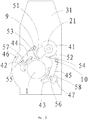
- Fig.s 3-4 more clearly illustrates the structure of a bottom mould positioning assembly.
- the bottom mould positioning assembly comprises a rotation member 41, multiple swing members cooperating with the rotation member 41 and a plurality of sliding blocks slidable in horizontal direction.
- One end of each of the multiple swing members is rotatably connected with the machine frame, and the other end is connected with one of the plurality of sliding blocks.
- the sliding blocks comprises a first sliding block 42 and a second sliding block 43 located at two opposite sides of the bottom mould 1, the multiple swing members comprise a first swing member 44 and a second swing member 45 rotatably connected with the machine frame.
- the bottom mould positioning assembly also comprises a first guide rail 46 and a second guide rail 47 fixedly disposed on the machine frame, and the first sliding block 42 and the second sliding block 43 respectively slide along the first guide rail 46 and the second guide rail 47.
- a first projection 55 and a second projection 56 respectively are formed on an upper surface of the first sliding block 42 and the second sliding block 43, a first sliding groove 57 and a second sliding groove 58 respectively are formed on other end of the first swing member 44 and the second swing member 45, the first projection 55 is slidably inserted into the first sliding groove 57, and the second projection 56 is slidably inserted into the second sliding groove 58.
- a first guiding surface 51 and a second guiding surface 52 are provided on the rotation member 41, a first protrusion 53 and a second protrusion 54 respectively are provided on the first swing member 44 and the second swing member 45.
- a first torsional spring 9 is arranged between the first swing member 44 and the machine frame
- a second torsional spring 10 is arranged between the second swing member 45 and the machine frame
- the two torsional springs respectively provide a restoring force for the two swing members.
- the first protrusion 53 moves away from the axis of rotation of the rotation shaft 21 under the guiding of the first guiding surface 51, the first swing member 44 is pushed by the rotation member 41 to rotate.
- the first torsional spring 9 provides an applied force for the first swing member 44 such that the first swing member 44 swings.
- the swinging principle of the second swing member 45 is the same as that of the first swing member 44.
- the rotation member 41 and the moving mould plate 3 are fixedly connected with the rotation shaft 21 which is driven by a power source to rotate around an axis of rotation.
- the rotation shaft 21 is configured as a cylinder, and its' shaft axis is the axis of rotation thereof.
- the rotation shaft 21 extends through the rotation member 41 and the moving mould plate 3 from down to up and drives them to rotate. It is required that the rotation shaft 21 drives the moving mould 3 to move towards or leave the fixed mould plate 2, thus, the rotation shaft 21 alternatively rotates between the positive direction and negative direction.
- a swing arm 22 is connected on the lower end of the rotation shaft 21, and a power source drives the rotation of the rotation shaft 21 by means of the swing arm 22.
- the power source drives the swing arm 22 to drive the rotation of the rotation shaft 21 in positive direction, such that the moving mould plate 3 rotates with the rotation of the rotation shaft 21 and draws close to the fixed mould plate 2, meanwhile, the rotation member 41 also rotates with the rotation shaft 21, the first protrusion 53 slide along the first guiding surface 51, the second protrusion 54 slide along the second guiding surface 52.
- the first swing member 44 swings under the pushing of the rotation member 41 or under the applied force of the first torsional spring 9, and the second swing member 45 swings under the pushing of the rotation member 41 or under the applied force of the second torsional spring 10, such that the first sliding block 42 and the second sliding block 43 respectively slide along the first guide rail 46 and the second guide rail 47, until the two sliding blocks are inserted between the bottom mould 1 and the machine frame and contact against the bottom mould 1 below the bottom mould 1, so that the bottom mould 1 is positioned.
- the machine frame comprises a support frame 31, an upper frame 32 located above the support frame 31 and an upright frame 33 fixedly connected between the support frame 31 and the upper frame 32. Both the mould opening and closing assembly and bottom mould positioning assembly are located above the support frame 31.
- a cam 11 is located below the support frame 31, one end of each of the first swing member and the second swing member is rotatably connected with the support frame 31, and the first guide rail 46 and the second guide rail 47 respectively are fixedly disposed on the support frame 31.
- a through-hole is opened on the support frame 31 for the rotation shaft 21 rotating therein, and the rotation shaft 21 is rotatable within the through-hole.
- the upper end of the rotation shaft 21 is rotatably connected with the upper frame 32.
Description
- The present invention relates to the field of processing equipment of a beverage bottle, and more particularly to a bottle blowing machine.
- Generally a bottle blowing machine comprises a mould opening and closing mechanism and a bottom mould positioning mechanism. A conventional mould opening and closing mechanism comprises a machine frame, a fixed mould plate and a moving mould plate which are mounted on the machine frame. A mould locking mechanism is provided at the joint of the fixed mould plate and the moving mould plate. The moving mould plate is L-shaped and driven by a mould opening and closing air cylinder. The mould opening and closing air cylinder drives a spline, and the spline drives a moving mould plate gear mounted on a gear shaft, and the gear shaft is connected with the moving mould plate and mounted on a support frame.
- A conventional bottom mould positioning mechanism, for example, a bottom mould locking mechanism of a linear bottle blowing machine as disclosed in patent publication No.
CN201755911U , comprises a mould mounting plate, a bottle mould, a bottom mould, an actuating mechansim, a positioning mechanism and a supporting seat. The end of the cavity of the bottle mould is sleeved with the bottom mould which is connected with the actuating mechanism. The positioning mechanism is horizontally disposed on the support seat and comprises a positioning block air cylinder and a positioning block connected with each other. The actuating mechanism comprises a bottom mould mounting plate and a bottom mould elevating air cylinder. An upper surface of the bottom mould mounting plate is connected with the bottom mould, and a lower surface of the bottom mould mounting plate is connected with the bottom mould elevating air cylinder which is mounted on a support frame. - Thus, in the prior art, the mould opening and closing mechanism and the bottom mould positioning mechanism are complicated in configuration and bulky, and each mechanism is self-driven, thereby leading to the inconvenience of operation and high cost.
- Futher devices are known from
US 2012/177771 A1 andDE202004017530U1 .US 2012/177771 A1 relates to a device for blow-molding containers, the device comprising a structure and a platform mounted to rotate on the structure about an axis of rotation, the platform being provided with blower members and with molds that are mounted under the blower members, each of which comprises a stationary mold portion and a movable mold portion that is movable by control means between an open position and a closed position for the mold, wherein the device includes blocking members for blocking the molds in the closed state, each blocking member comprising a strut mounted on the platform to move between a retracted position and a blocking position.DE202004017530U1 relates to a tool clamp for a blow molding machine, wherein, when a moving tool frame(402) and a fixed tool frame(401) are closed against each other they form a chamber surrounding a movable tool halves(501,502), contact surfaces(7) between the closed tool frames and tool halves are arc-shaped, the chamber is round to accommodate the moving(502) and fixed tool halves, positioning blocks(8) cranked outwards from the tool halves engage in corresponding holes(9) in the moving frame(402) and fixed frame(401), ring-shaped securing blocks(10) screwed onto the tool frames hold the positioning blocks in their respective holes. - An object of the invention is to provide an improved linkage of mould opening and closing and bottom mould positioning.
- In order to solve the above technical problem, the following technical solution is utilized in the invention.
- A bottle blowing machine, comprising
- a machine frame;
- a mould opening and closing assembly having a mould opening state and a mould closing state, which comprises a bottom mould movable relative to the machine frame in up-down direction, a fixed mould plate fixedly disposed on the machine frame, and a moving mould plate rotatable relative to the machine frame; and
- a bottom mould positioning assembly for fixing the bottom mould with the machine frame of the bottle blowing machine;
when the mould opening and closing assembly is in the mould closing state, the moving mould plate is engaged with the fixed mould plate, and the moving mould plate, the fixed mould plate and the bottom mould together enclose to provide a cavity; - wherein the bottom mould positioning assembly comprises:
- a plurality of sliding blocks slidably disposed on the machine frame;
- multiple swing members swingably disposed on the machine frame for driving the sliding of the plurality of sliding blocks; and
- a rotation member rotatable relative to the machine frame for driving the swinging of the swing members relative to the machine frame during its' rotation, the moving mould plate and the rotation member respectively are fixedly connected on a rotation shaft which is driven by a power source to rotate around an axis of rotation;
wherein when the mould opening and closing assembly is in the mould closing state, the plurality of sliding blocks are inserted between the bottom mould and the machine frame and contact against the bottom mould, when the mould opening and closing assembly is in the mould opening state, the plurality of sliding blocks are detached from the bottom mould. The rotation shaft drives the moving mould plate and the rotation member to rotate, and the rotation of the rotation member is converted into the sliding of the sliding blocks by means of the swing members, and thus the mould closing and the positioning of the bottom mould in the mould closing state are synchronously achieved, vice versa, the mould opening and the releasing of the bottom mould in mould opening state also can be synchronously achieved.
- Preferably, a through-hole is opened on each of the rotation member and the moving mould plate for the rotation shaft extending through the rotation member and the moving mould plate from bottom to top.
- More preferably, a swing arm is connected on a lower end of the rotation shaft, and a power source drives the rotation of the rotation shaft by the swing arm.
- Preferably, the plurality of sliding blocks comprises a first sliding block and a second sliding block located at two opposite sides of the bottom mould. The bottom mould positioning assembly also comprises a first guide rail and a second guide rail fixedly disposed on the machine frame, the first sliding block is slidably disposed on the first guide rail, and the second sliding block is slidably disposed on the second guide rail. Thus, the bilateral positioning of the bottom mould is achieved by means of the two sliding blocks.
- Still more preferably, the multiple swing members comprise a first swing member and a second swing member which respectively are rotatably connected with the machine frame. The first swing member and the second swing member respectively and correspondingly drive the sliding of the first sliding block and the second sliding block. Thus, the sliding of the two sliding blocks are controlled separately by the swinging of the two swing members, this will simplify controlling means.
- Preferably, a first sliding groove is opened on the first swing member at a distance from the connecting position of the first swing member with the machine frame, and a second sliding groove is opened on the second swing member at a distance from the connecting position of the second swing member with the machine frame, a first projection and a second projection respectively are formed on an upper surface of the first sliding block and the second sliding block, the first projection is slidably inserted into the first sliding groove, and the second projection is slidably inserted into the second sliding groove. The portions of the two swing members where the sliding grooves are opened respectively form a transmission fork configuration, and the swing members control the sliding of the sliding blocks by means of the transmission fork configurations.
- More preferably, the rotation member has a first guiding surface and a second guiding surface on its' side surface, a first protrusion protruding towards the rotation member is formed on the first swing member, a second protrusion protruding towards the rotation member is formed on the second swing member. When the rotation member rotates relative to the machine frame, the first guiding surface slidably contacts with the first protrusion, the second guiding surface slidably contacts with the second protrusion, and the distance between the contact position of the first guiding surface with the first protrusion and the axis of rotation of the rotation member and the distance between the contact position of the second guiding surface with the second protrusion and the axis of rotation of the rotation member respectively change with the rotation of the rotation member. This change in distance will produce a guiding effect such that the protrusions will move and the two swing members swing correspondingly.
- More preferably, an elastic member is arranged between each of the swing members and the machine frame for providing a restoring force for the swing members. For example, in the course of rotation of the rotating member, when the contact positions of the protrusions with the guiding surfaces get farther and farther away from the second axis, the swing members are pushed by the rotating member to swing. Otherwise, in the course of rotation of the rotating member, when the contact positions of the protrusion and the guiding surfaces get nearer and nearer to the second axis, an external force is required to drive the swing members to swing, and the elastic member hereby is used for providing such an external force. Certainly, the external force can be provided in other ways, for example, the swing members are driven by the rotating member.
- In a preferable embodiment, the mould opening and closing assembly also comprises a locking mechanism for locking the fixed mould plate with the moving mould plate in the mould closing state. The locking mechanism comprises: at least one first connecting convex platform formed on the moving mould plate, a pin hole being opened on the first connecting convex platform; a second connecting convex platform formed on the fixed mould plate for cooperating with the first connecting convex platform, a mounting hole being opened on the second connecting convex platform, and a locking pin movably or extendably inserted into the mounting hole of the second connecting convex platform. A connecting shaft extends through the fixed mould plate, and the connecting shaft is connected with the locking pin in a transmission way. When the mould opening and closing assembly is in the mould closing state, the locking pin extends through the second connecting convex platform and into the pin hole to lock the moving mould plate with the fixed mould plate, in such a way that the locking pin is allowed to be detached from the pin hole and enter into mounting hole of the second connecting convex platform when the moving mould plate is needed to be opened relative to the fixed mould plate.
- In a particular embodiment, the machine frame comprises a support frame, an upper frame located above the support frame and an upright frame fixedly connected between the support frame and the upper frame, both the mould opening and closing assembly and bottom mould positioning assembly are located above the support frame, a through-hole is opened on the support frame, the rotation shaft rotatably extends through the through-hole such that a lower portion of the rotation shaft extends below the support frame. One end of the first swing member and one end of the second swing member respectively are rotatably connected with the support frame, and the guide rails as described before respectively are fixedly provided on the support frame. Based on such a design, the power source, the actuating mechanisms located between the power source and the rotation shaft and the like, can be arranged below the support frame, such that the space below the support frame can be reasonably utilized, and the configuration of the whole bottle blowing machine is more compact.
- More preferably, an upper end of the rotation shaft is rotatably connected with the upper frame.
- Due to the above technical solution, the present invention has the following advantages as compared with the prior art: the linkage of the mould opening and closing assembly and the bottom mould positioning assembly are driven by one rotation shaft. Thus, the driving is achieved by a simple configuration, and the whole device of the invention has simple structure and convenient operation and small volume.
-
-
Fig.1 is a assembly drawing of a mould opening and closing assembly and a bottom mould assembly and other parts according to the invention, wherein the mould opening and closing is in the mould closing state; -
Fig.2 is a assembly drawing of a mould opening and closing assembly and a bottom mould assembly and other parts according to the invention, wherein the mould opening and closing assembly is in the mould opening state; -
Fig.3 is a top view of the bottom mould positioning mechanism in mould opening state according to one embodiment of the invention, ; -
Fig.4 is a top view of the bottom mould positioning mechanism offig.3 in the mould closing state.
wherein: 1. a bottom mould; 2. a fixed mould plate; 3. a moving mould plate; 4. a first connecting convex platform; 5. a pin hole; 6. a second connecting convex platform; 7. a connecting shaft; 8. a locking pin; 9. a first torsional spring; 10. a second torsional spring; 21. a rotation shaft; 22. a swing arm; 31. a support frame; 32. an upper frame; 33. an upright frame; 41. a rotation member; 42. a first sliding block; 43. a second sliding block; 44. a first swing member; 45. a second swing member; 46. a first guide rail; 47. a second guide rail; 51. a first guiding surface; 52. a second guiding surface; 53. a first protrusion; 54. a second protrusion; 55. a first projection; 56. a second projection; 57. a first sliding groove; 58. a second sliding groove. - The present invention will be described hereinafter with reference to the accompanying drawings. It is to be noted, however, that the drawings are given only for illustrative purpose and therefore not to be considered as limiting of its scope, for the invention may admit to other equally effective embodiments.
-
Fig.1-2 show a mould opening and closing assembly, a bottom mould positioning assembly and a linkage for them, all of which are mounted on a bottle blowing machine for use. The structure of the bottle blowing machine is well known in the art, and the other parts of the bottle blowing machine are not involved in the invention, thus, the bottle blowing machine is partially shown in the invention, instead of the whole structure. - The mould opening and closing assembly comprises a
bottom mould 1 movable relative to a machine frame in up-down direction, a fixed mould plate 2 disposed on the machine frame of the bottle blowing machine, and a movingmould plate 3 cooperating with the fixed mould plate 2. The mould opening and closing assembly has a mould opening state and a mould closing state, when in the mould closing state, thebottom mould 1, the fixed mould plate 2 and the movingmould plate 3 together enclose to provide a cavity, and the movingmould plate 3 is engaged with the fixed mould plate 2, as shown infig.1 . It can be seen from thefig.2 that, the fixed mould plate 2 and the movingmould plate 3 respectively are provided with a mould (not indicated by a reference number), and the moulds on the fixed mould plate 2 and the movingmould plate 3 cooperate with each other to shape up a bottle. - The mould opening and closing assembly also comprises a locking mechanism for locking the fixed mould plate 2 with the moving
mould plate 3 in the mould closing state. At least one first connectingconvex platform 4 is provided on the movingmould plate 3, a second connectingconvex platform 6 is disposed on the fixed mould plate 2, in the embodiment shown infig.2 , there are three first connectingconvex platforms 4, a notch is formed between adjacent two first connectingconvex platforms 4. There are three second connectingconvex platforms 6, a notch also is formed between adjacent two first connectingconvex platforms 4. The first connectingconvex platforms 4 and the second connectingconvex platforms 6 are staggered with each other, such that a connecting convex platform of them corresponds to a notch of the other one, and the movingmould plate 3 and the fixed mould plate 2 are cooperated and connected with each other in closing state by means of the connecting convex platforms. Apin hole 5 is opened on each first connectingconvex platform 4, and preferably thepin hole 5 extends through the first connectingconvex platform 4 in up-down direction. A mounting hole (not shown by a reference number) is opened on each second connectingconvex platform 6, and a locking pin 8 is movably or extendably provided in the mounting hole, and the quantity of the locking pins 8 is the same as that of the second connectingconvex platforms 6. A connectingshaft 7 extends through the fixed mould plate 2, and the connectingshaft 7 is connected with the locking pin 8 in a transmission way. The connectingshaft 7 and locking pin 8 shown infig.2 are parallel to each other, and the connectingshaft 7 is connected with the locking pin 8 by a connecting rod in a transmission way, and one lowest locking pin 8 is directly connected with a driving block. When in the mould closing, the first connectingconvex platforms 4 of the movingmould plate 3 are inserted into the notches of the second connectingconvex platforms 6 of the fixed mould plate 2, the driving block is pulled upwards, such that the connectingshaft 7 is driven by the driving block, and the connectingshaft 7 drives the locking pins 8 to extend through the second connectingconvex platforms 6 and into the pin holes 5, and thus the movingmould plate 3 and the fixed mould plate 2 are locked with each other. When the mould opening is desired, the locking pins 8 are driven by the connectingshaft 7 to leave the pin holes 5 and enter into the mounting holes of the second connectingconvex platforms 6, such that the movingmould plate 3 can be separated from the fixed mould plate 2. -
Fig.s 3-4 more clearly illustrates the structure of a bottom mould positioning assembly. - Referring to
fig.s 2 and3-4 , the bottom mould positioning assembly comprises arotation member 41, multiple swing members cooperating with therotation member 41 and a plurality of sliding blocks slidable in horizontal direction. One end of each of the multiple swing members is rotatably connected with the machine frame, and the other end is connected with one of the plurality of sliding blocks. Specifically, the sliding blocks comprises a first slidingblock 42 and a second slidingblock 43 located at two opposite sides of thebottom mould 1, the multiple swing members comprise afirst swing member 44 and asecond swing member 45 rotatably connected with the machine frame. - The bottom mould positioning assembly also comprises a
first guide rail 46 and asecond guide rail 47 fixedly disposed on the machine frame, and the first slidingblock 42 and the second slidingblock 43 respectively slide along thefirst guide rail 46 and thesecond guide rail 47. - A
first projection 55 and asecond projection 56 respectively are formed on an upper surface of the first slidingblock 42 and the second slidingblock 43, a first slidinggroove 57 and a second slidinggroove 58 respectively are formed on other end of thefirst swing member 44 and thesecond swing member 45, thefirst projection 55 is slidably inserted into the first slidinggroove 57, and thesecond projection 56 is slidably inserted into the second slidinggroove 58.
afirst guiding surface 51 and asecond guiding surface 52 are provided on therotation member 41, afirst protrusion 53 and asecond protrusion 54 respectively are provided on thefirst swing member 44 and thesecond swing member 45. When therotation member 41 rotates, thefirst protrusion 53 slides along the first guidingsurface 51, and thesecond protrusion 54 slides along thesecond guiding surface 52, as shown infig.s 3-4 . - Preferably, a first
torsional spring 9 is arranged between thefirst swing member 44 and the machine frame, a secondtorsional spring 10 is arranged between thesecond swing member 45 and the machine frame, the two torsional springs respectively provide a restoring force for the two swing members. - When the
first protrusion 53 moves away from the axis of rotation of therotation shaft 21 under the guiding of the first guidingsurface 51, thefirst swing member 44 is pushed by therotation member 41 to rotate. When the contact position of the first guidingsurface 51 with thefirst protrusion 53 becomes nearer and nearer to the axis of rotation of therotation shaft 21, the firsttorsional spring 9 provides an applied force for thefirst swing member 44 such that thefirst swing member 44 swings. The swinging principle of thesecond swing member 45 is the same as that of thefirst swing member 44. - The
rotation member 41 and the movingmould plate 3 are fixedly connected with therotation shaft 21 which is driven by a power source to rotate around an axis of rotation. In the embodiment shown infig.s 1-4 , therotation shaft 21 is configured as a cylinder, and its' shaft axis is the axis of rotation thereof. Therotation shaft 21 extends through therotation member 41 and the movingmould plate 3 from down to up and drives them to rotate. It is required that therotation shaft 21 drives the movingmould 3 to move towards or leave the fixed mould plate 2, thus, therotation shaft 21 alternatively rotates between the positive direction and negative direction. - In the embodiment shown in
fig.s 1-2 , aswing arm 22 is connected on the lower end of therotation shaft 21, and a power source drives the rotation of therotation shaft 21 by means of theswing arm 22.
when the mould closing is desired, the power source drives theswing arm 22 to drive the rotation of therotation shaft 21 in positive direction, such that the movingmould plate 3 rotates with the rotation of therotation shaft 21 and draws close to the fixed mould plate 2, meanwhile, therotation member 41 also rotates with therotation shaft 21, thefirst protrusion 53 slide along the first guidingsurface 51, thesecond protrusion 54 slide along thesecond guiding surface 52. Thefirst swing member 44 swings under the pushing of therotation member 41 or under the applied force of the firsttorsional spring 9, and thesecond swing member 45 swings under the pushing of therotation member 41 or under the applied force of the secondtorsional spring 10, such that the first slidingblock 42 and the second slidingblock 43 respectively slide along thefirst guide rail 46 and thesecond guide rail 47, until the two sliding blocks are inserted between thebottom mould 1 and the machine frame and contact against thebottom mould 1 below thebottom mould 1, so that thebottom mould 1 is positioned. - When the mould opening is desired, the
rotation shaft 21 reversely rotates relative to the opposite direction, the movingmould plate 3 is opened relative to the fixed mould plate 2, and therotation member 41 also inversely and synchronously rotates, the two sliding blocks respectively are driven by thefirst swing member 44 and thesecond swing member 45 to move away from thebottom mould 1. The term "positive direction" and "negative direction" mentioned herein and throughout the invention are described only for illustrating two kinds of movement in opposite directions, and not strictly corresponding to the clockwise or anti-clockwise direction. In the embodiment shown infig.s 1-4 , the "positive direction" corresponds to the anti-clockwise direction, and the "negative direction" corresponds to the clockwise direction. - It can be seen from the above description that, the linkage of the mould opening and closing and bottom mould positioning is achieved by means of the above structure.
- When in the mould closing state, a gap is formed between the
bottom mould 1 and the machine frame, the first slidingblock 42 and the second slidingblock 43 respectively slide along thefirst guide rail 46 and thesecond guide rail 47 towards the gap and insert into the gap, and contact against with thebottom mould 1 and machine frame. The machine frame comprises asupport frame 31, anupper frame 32 located above thesupport frame 31 and anupright frame 33 fixedly connected between thesupport frame 31 and theupper frame 32. Both the mould opening and closing assembly and bottom mould positioning assembly are located above thesupport frame 31. A cam 11 is located below thesupport frame 31, one end of each of the first swing member and the second swing member is rotatably connected with thesupport frame 31, and thefirst guide rail 46 and thesecond guide rail 47 respectively are fixedly disposed on thesupport frame 31. A through-hole is opened on thesupport frame 31 for therotation shaft 21 rotating therein, and therotation shaft 21 is rotatable within the through-hole. The upper end of therotation shaft 21 is rotatably connected with theupper frame 32. The above embodiment is described for illustrating the technical concept and features of the invention, the aim is intended to enable a person skilled in the art to appreciate the content of the invention and further implement it, and the protecting scope of the invention can not be limited hereby.
Claims (11)
- A bottle blowing machine, comprising
a machine frame;
a mould opening and closing assembly having a mould opening state and a mould closing state, which comprises a bottom mould (1) movable relative to the machine frame in up-down direction, a fixed mould plate (2) fixedly disposed on the machine frame, and a moving mould plate (3) rotatable relative to the machine frame; and
a bottom mould positioning assembly for fixing the bottom mould (1) with the machine frame of the bottle blowing machine; wherein
when the mould opening and closing assembly is in the mould closing state, the moving mould plate (3) is engaged with the fixed mould plate (2), and the moving mould plate (3), the fixed mould plate (2) and the bottom mould (1) together enclose to provide a cavity;
characterized in that
the bottom mould positioning assembly comprises:a plurality of sliding blocks slidably disposed on the machine frame;multiple swing members swingably disposed on the machine frame for driving the sliding of the plurality of sliding blocks; anda rotation member (41) rotatable relative to the machine frame for driving the swinging of the swing members relative to the machine frame during its' rotation, the moving mould plate (3) and the rotation member (41) respectively being fixedly connected with a rotation shaft (21) which is driven by a power source to rotate around an axis of rotation;when the mould opening and closing assembly is in the mould closing state, the plurality of sliding blocks are inserted between the bottom mould (1) and the machine frame and contact against the bottom mould (1), when the mould opening and closing assembly is in the mould opening state, the plurality of sliding blocks are detached from the bottom mould (1). - The bottle blowing machine as claimed in claim 1, wherein a through-hole is opened on each of the rotation member (41) and the moving mould plate (3), and the rotation shaft (21) sequentially extending through the rotation member (41) and the moving mould plate (3) from bottom to top and connecting with them.
- The bottle blowing machine as claimed in claim 1, wherein a swing arm (22) is connected on a lower end of the rotation shaft (21), and a power source driving the rotation of the rotation shaft (21) by the swing arm (22).
- The bottle blowing machine as claimed in claim 1, wherein the plurality of swing members comprise a first swing member (44) and a second swing member (45) which respectively are rotatably connected with the machine frame, and the first swing member (44) and the second swing member (45) respectively and correspondingly driving the sliding of the first sliding block (42) and the second sliding block (43).
- The bottle blowing machine as claimed in claim 4, wherein a first sliding groove (57) is opened on the first swing member (44) at a distance from the connecting position of the first swing member (44) with the machine frame, and a second sliding groove (58) is opened on the second swing member (45) at a distance from the connecting position of the second swing member (45) with the machine frame, a first projection (55) and a second projection (56) respectively being formed on an upper surface of the first sliding block (42) and the second sliding block (43), the first projection (55) being slidably inserted into the first sliding groove (57), and the second projection (56) being slidably inserted into the second sliding groove (58).
- The bottle blowing machine as claimed in claim 1, wherein the rotation member (41) has a first guiding surface (51) and a second guiding surface (52) on its' side surface, a first protrusion(53) protruding towards the rotation member (41) being formed on the first swing member (44), a second protrusion (54) protruding towards the rotation member (41) being formed on the second swing member (45), when the rotation member (41) rotates relative to the machine frame, the first guiding surface (51) slidably contacts with the first protrusion (53), the second guiding surface (52) slidably contacts with the second protrusion (54), and the distance between the contact position of the first guiding surface (51) with the first protrusion (53) and the axis of rotation and the distance between the contact position of the second guiding surface (52) with the second protrusion (54) and the axis of rotation respectively changing with the rotation of the rotation member (41).
- The bottle blowing machine as claimed in any of claim 1-6, wherein the mould opening and closing assembly also comprises a locking mechanism for locking the fixed mould plate (2) with the moving mould plate (3) in the mould closing state, the locking mechanism comprising:at least one first connecting convex platform (4) formed on the moving mould plate (3), a pin hole (5) being opened on the first connecting convex platform (4);a second connecting convex platform (6) formed on the fixed mould plate (2) for cooperating with the first connecting convex platform (4), a mounting hole being opened on the second connecting convex platform (6); anda locking pin (8) movably or extendably inserted into the mounting hole of the second connecting convex platform (6), a connecting shaft extending through the fixed mould plate (2), and the the connecting shaft being connected with the locking pin (8) in a transmission way, when the mould opening and closing assembly is in the mould closing state, the locking pin(8) extending through the second connecting convex platform (6) and into the pin hole (5) to lock the moving mould plate (3) with the fixed mould plate (2), in such a way that the locking pin (8) is allowed to be detached from the pin hole (5) and enter into the mounting hole of the second connecting convex platform (6).
- The bottle blowing machine as claimed in any of claims 1-6, wherein the machine frame comprises a support frame (31), an upper frame (32) located above the support frame (31) and an upright frame (33) fixedly connected between the support frame (31) and the upper frame (32), both the mould opening and closing assembly and bottom mould positioning assembly being located above the support frame (31), a through-hole being opened on the support frame (31), the rotation shaft (21) rotatably extending through the through-hole such that a lower portion of the rotation shaft (21) extending below the support frame (31).
- The bottle blowing machine as claimed in claim 8, wherein the first swing member and the second swing member respectively are rotatably connected with the support frame (31).
- The bottle blowing machine as claimed in claim 8, wherein an upper end of the rotation shaft (21) is rotatably connected with the upper frame (32).
- The bottle blowing machine as claimed in any of claims 1-6, wherein an elastic member is arranged between each of the swing members and the machine frame.
Applications Claiming Priority (3)
| Application Number | Priority Date | Filing Date | Title |
|---|---|---|---|
| CN201310088430.9A CN103171132B (en) | 2013-03-19 | 2013-03-19 | Link mechanism for opening and closing die and positioning bottom die by single shaft |
| PCT/CN2013/074917 WO2014146324A1 (en) | 2013-03-19 | 2013-04-27 | Linkage mechanism between uniaxial die opening and closing and bottom die positioning |
| EP13878760.1A EP2977176B1 (en) | 2013-03-19 | 2013-04-27 | System with linkage mechanism between uniaxial die opening and closing and bottom die positioning |
Related Parent Applications (3)
| Application Number | Title | Priority Date | Filing Date |
|---|---|---|---|
| PCT/CN2013/074917 Previously-Filed-Application WO2014146324A1 (en) | 2013-03-19 | 2013-04-27 | Linkage mechanism between uniaxial die opening and closing and bottom die positioning |
| EP13878760.1A Division-Into EP2977176B1 (en) | 2013-03-19 | 2013-04-27 | System with linkage mechanism between uniaxial die opening and closing and bottom die positioning |
| EP13878760.1A Division EP2977176B1 (en) | 2013-03-19 | 2013-04-27 | System with linkage mechanism between uniaxial die opening and closing and bottom die positioning |
Publications (2)
| Publication Number | Publication Date |
|---|---|
| EP3323587A1 EP3323587A1 (en) | 2018-05-23 |
| EP3323587B1 true EP3323587B1 (en) | 2020-05-20 |
Family
ID=48631536
Family Applications (2)
| Application Number | Title | Priority Date | Filing Date |
|---|---|---|---|
| EP13878760.1A Active EP2977176B1 (en) | 2013-03-19 | 2013-04-27 | System with linkage mechanism between uniaxial die opening and closing and bottom die positioning |
| EP17205968.5A Active EP3323587B1 (en) | 2013-03-19 | 2013-04-27 | A bottle blowing machine |
Family Applications Before (1)
| Application Number | Title | Priority Date | Filing Date |
|---|---|---|---|
| EP13878760.1A Active EP2977176B1 (en) | 2013-03-19 | 2013-04-27 | System with linkage mechanism between uniaxial die opening and closing and bottom die positioning |
Country Status (3)
| Country | Link |
|---|---|
| EP (2) | EP2977176B1 (en) |
| CN (1) | CN103171132B (en) |
| WO (1) | WO2014146324A1 (en) |
Families Citing this family (9)
| Publication number | Priority date | Publication date | Assignee | Title |
|---|---|---|---|---|
| CN103171134A (en) * | 2013-03-19 | 2013-06-26 | 江苏新美星包装机械股份有限公司 | Die sinking and assembling mechanism |
| CN103171131B (en) * | 2013-03-19 | 2014-12-31 | 江苏新美星包装机械股份有限公司 | Bottom die double-side locking mechanism |
| CN107009600B (en) * | 2017-06-06 | 2022-09-16 | 全冠(福建)机械工业有限公司 | Mould opening and closing device of blow molding machine |
| CN110358671A (en) * | 2018-04-10 | 2019-10-22 | 北京慧荣和科技有限公司 | Multi link open-and-close mechanism |
| CN109878017A (en) * | 2019-03-28 | 2019-06-14 | 罗红军 | Widening mechanism |
| CN115008682B (en) * | 2022-05-30 | 2023-09-05 | 深圳市鹏亿发精密模具有限公司 | Maintenance type precise die capable of being opened in rotating mode |
| CN114905725B (en) * | 2022-06-01 | 2023-11-17 | 湖南远超环保科技有限公司 | Quick die changing device of automatic bottle blowing machine |
| CN115071004B (en) * | 2022-06-23 | 2023-09-08 | 晋江中天模具有限公司 | PVC polychrome rotary die utensil |
| CN117162385A (en) * | 2023-08-10 | 2023-12-05 | 佛山泡趣创新科技有限公司 | Injection mold assembled in mold |
Family Cites Families (19)
| Publication number | Priority date | Publication date | Assignee | Title |
|---|---|---|---|---|
| DE4212583A1 (en) * | 1992-04-15 | 1993-10-21 | Krupp Corpoplast Masch | Blow molding device |
| FR2793722B1 (en) * | 1999-05-17 | 2001-08-03 | Sidel Sa | BLOWING MACHINE COMPRISING A CLOSING AND LOCKING MECHANISM COMBINED WITH A MOLDING UNIT |
| FR2841495B1 (en) * | 2002-06-27 | 2004-11-12 | Sidel Sa | DEVICE FOR MOLDING, BY BLOWING OR STRETCH-BLOWING, CONTAINERS OF THERMOPLASTIC MATERIAL |
| DE202004017530U1 (en) * | 2004-05-18 | 2005-03-10 | Guo, Xinan, Foshan | Tool clamp for a blow molding machine has tool frames with arc-shaped contact surfaces enclosing tool halves with corresponding surfaces |
| DE102004045405A1 (en) * | 2004-09-18 | 2006-04-13 | Sig Technology Ltd. | Device for blow molding containers |
| KR100758992B1 (en) * | 2005-01-14 | 2007-09-14 | 주식회사 연합조명 | Manufacturing apparatus of cover for lighting |
| FR2889994B1 (en) * | 2005-08-29 | 2007-11-16 | Sidel Sas | MOLDING UNIT FOR THERMOFORMABLE CONTAINER BLOWING MACHINE |
| DE102007008023A1 (en) * | 2007-02-15 | 2008-08-21 | Sig Technology Ag | Container molding method for blow station, involves positioning horizontal bar by using electro-mechanical horizontal bar drive, and transforming rotary movement of motor shaft into stroke movement of horizontal bar by coupling device |
| DE102007022638A1 (en) * | 2007-05-15 | 2008-11-20 | Sig Technology Ag | Device for blow molding containers |
| CN101524891B (en) * | 2008-03-04 | 2013-04-17 | 汪祥建 | Mould locking air pressure swelling mechanism for rotary bottle blowing machine |
| DE102008063939A1 (en) * | 2008-12-19 | 2010-07-01 | Krones Ag | blow |
| CN201325179Y (en) * | 2008-12-25 | 2009-10-14 | 解冬正 | Die opening and locking mechanism of bottle blowing machine |
| CN201353883Y (en) * | 2009-01-06 | 2009-12-02 | 郭锡南 | Locking mode mechanism |
| CN102133797B (en) * | 2010-01-27 | 2013-08-21 | 王自强 | Movable mold board and bottom mold linkage mechanism of plastic bottle-blowing machine |
| CN201755911U (en) | 2010-08-05 | 2011-03-09 | 杨茂林 | Bottom die locking device of linear bottle blowing machine |
| FR2969955B1 (en) * | 2011-01-04 | 2013-02-01 | Serac Group | DEVICE FOR BLOWING CONTAINERS |
| DE202011109976U1 (en) * | 2011-06-03 | 2012-09-11 | Krones Ag | Device and system for stretch blow molding of plastic preforms |
| CN102962989B (en) * | 2012-11-22 | 2015-07-29 | 广州达意隆包装机械股份有限公司 | The link gear of bottle blowing machine limit mould and bed die |
| CN203157125U (en) * | 2013-03-19 | 2013-08-28 | 江苏新美星包装机械股份有限公司 | Uniaxial die opening and closing and bottom die locating linkage mechanism |
-
2013
- 2013-03-19 CN CN201310088430.9A patent/CN103171132B/en active Active
- 2013-04-27 EP EP13878760.1A patent/EP2977176B1/en active Active
- 2013-04-27 EP EP17205968.5A patent/EP3323587B1/en active Active
- 2013-04-27 WO PCT/CN2013/074917 patent/WO2014146324A1/en active Application Filing
Non-Patent Citations (1)
| Title |
|---|
| None * |
Also Published As
| Publication number | Publication date |
|---|---|
| EP2977176B1 (en) | 2018-07-25 |
| EP2977176A1 (en) | 2016-01-27 |
| CN103171132B (en) | 2015-05-20 |
| WO2014146324A1 (en) | 2014-09-25 |
| CN103171132A (en) | 2013-06-26 |
| EP3323587A1 (en) | 2018-05-23 |
| EP2977176A4 (en) | 2016-11-09 |
Similar Documents
| Publication | Publication Date | Title |
|---|---|---|
| EP3323587B1 (en) | A bottle blowing machine | |
| EP2977175B1 (en) | Bottle blowing machine having bottom die lifting clamping mechanism | |
| EP2977173B1 (en) | Linkage mechanism between lifting and bilateral positioning of bottom die | |
| EP2977171B1 (en) | Bottle blowing machine | |
| EP2977174B1 (en) | Linkage mechanism between uniaxial die opening and closing and bottom die lifting | |
| EP2977179B1 (en) | Bottle blowing machine | |
| US9050749B1 (en) | Blow molding device for a rotary bottle blowing machine | |
| EP2977169B1 (en) | Blow mould with linkage mechanism between single shaft die opening and closing and bottom die clamping | |
| US5326250A (en) | Opening and closing mechanism for portfolio blowing and blowing-stretching mold | |
| EP2977180B1 (en) | Link mechanism for opening and closing die and positioning bottom die by single shaft | |
| WO2015029540A1 (en) | Machine tool | |
| KR20140102828A (en) | Opening and closing device of air vent for vehicle | |
| JP6780016B2 (en) | Furniture drive | |
| EP2977170B1 (en) | Linkage mechanism between bottom die lifting and unilateral clamping | |
| KR101162825B1 (en) | Sliding door apparatus | |
| EP2977181B1 (en) | System with bottom die lifting mechanism | |
| EP2977177B1 (en) | A system with bilateral clamping mechanism for bottom die | |
| EP2977178B1 (en) | Blow moudling machine with mould locking means | |
| KR101975809B1 (en) | High-speed switching device for a vehicle blocking the bar | |
| JP2010144461A (en) | Window opening and closing device | |
| EP2145861B1 (en) | Molds opening/closing group of a forming glass machine items | |
| KR20110086282A (en) | A door closing supporting apparatus | |
| JP4568178B2 (en) | Injection molding machine | |
| KR101555633B1 (en) | Supporting deivce for mold | |
| CN108623133B (en) | Inversion unit for glassware forming machine |
Legal Events
| Date | Code | Title | Description |
|---|---|---|---|
| PUAI | Public reference made under article 153(3) epc to a published international application that has entered the european phase |
Free format text: ORIGINAL CODE: 0009012 |
|
| STAA | Information on the status of an ep patent application or granted ep patent |
Free format text: STATUS: THE APPLICATION HAS BEEN PUBLISHED |
|
| AC | Divisional application: reference to earlier application |
Ref document number: 2977176 Country of ref document: EP Kind code of ref document: P |
|
| AK | Designated contracting states |
Kind code of ref document: A1 Designated state(s): AL AT BE BG CH CY CZ DE DK EE ES FI FR GB GR HR HU IE IS IT LI LT LU LV MC MK MT NL NO PL PT RO RS SE SI SK SM TR |
|
| AX | Request for extension of the european patent |
Extension state: BA ME |
|
| STAA | Information on the status of an ep patent application or granted ep patent |
Free format text: STATUS: REQUEST FOR EXAMINATION WAS MADE |
|
| 17P | Request for examination filed |
Effective date: 20181115 |
|
| RBV | Designated contracting states (corrected) |
Designated state(s): AL AT BE BG CH CY CZ DE DK EE ES FI FR GB GR HR HU IE IS IT LI LT LU LV MC MK MT NL NO PL PT RO RS SE SI SK SM TR |
|
| REG | Reference to a national code |
Ref country code: DE Ref legal event code: R079 Ref document number: 602013069339 Country of ref document: DE Free format text: PREVIOUS MAIN CLASS: B29C0045640000 Ipc: B29C0049560000 |
|
| GRAP | Despatch of communication of intention to grant a patent |
Free format text: ORIGINAL CODE: EPIDOSNIGR1 |
|
| STAA | Information on the status of an ep patent application or granted ep patent |
Free format text: STATUS: GRANT OF PATENT IS INTENDED |
|
| RIC1 | Information provided on ipc code assigned before grant |
Ipc: B29C 49/48 20060101ALN20200206BHEP Ipc: B29C 33/20 20060101ALI20200206BHEP Ipc: B29C 49/36 20060101ALN20200206BHEP Ipc: B29C 33/26 20060101ALN20200206BHEP Ipc: B29C 49/56 20060101AFI20200206BHEP |
|
| INTG | Intention to grant announced |
Effective date: 20200221 |
|
| RIC1 | Information provided on ipc code assigned before grant |
Ipc: B29C 33/26 20060101ALN20200210BHEP Ipc: B29C 49/56 20060101AFI20200210BHEP Ipc: B29C 33/20 20060101ALI20200210BHEP Ipc: B29C 49/48 20060101ALN20200210BHEP Ipc: B29C 49/36 20060101ALN20200210BHEP |
|
| GRAS | Grant fee paid |
Free format text: ORIGINAL CODE: EPIDOSNIGR3 |
|
| GRAA | (expected) grant |
Free format text: ORIGINAL CODE: 0009210 |
|
| STAA | Information on the status of an ep patent application or granted ep patent |
Free format text: STATUS: THE PATENT HAS BEEN GRANTED |
|
| AC | Divisional application: reference to earlier application |
Ref document number: 2977176 Country of ref document: EP Kind code of ref document: P |
|
| AK | Designated contracting states |
Kind code of ref document: B1 Designated state(s): AL AT BE BG CH CY CZ DE DK EE ES FI FR GB GR HR HU IE IS IT LI LT LU LV MC MK MT NL NO PL PT RO RS SE SI SK SM TR |
|
| REG | Reference to a national code |
Ref country code: GB Ref legal event code: FG4D |
|
| REG | Reference to a national code |
Ref country code: CH Ref legal event code: EP |
|
| REG | Reference to a national code |
Ref country code: DE Ref legal event code: R096 Ref document number: 602013069339 Country of ref document: DE |
|
| REG | Reference to a national code |
Ref country code: AT Ref legal event code: REF Ref document number: 1272330 Country of ref document: AT Kind code of ref document: T Effective date: 20200615 |
|
| REG | Reference to a national code |
Ref country code: LT Ref legal event code: MG4D |
|
| REG | Reference to a national code |
Ref country code: NL Ref legal event code: MP Effective date: 20200520 |
|
| PG25 | Lapsed in a contracting state [announced via postgrant information from national office to epo] |
Ref country code: IS Free format text: LAPSE BECAUSE OF FAILURE TO SUBMIT A TRANSLATION OF THE DESCRIPTION OR TO PAY THE FEE WITHIN THE PRESCRIBED TIME-LIMIT Effective date: 20200920 Ref country code: LT Free format text: LAPSE BECAUSE OF FAILURE TO SUBMIT A TRANSLATION OF THE DESCRIPTION OR TO PAY THE FEE WITHIN THE PRESCRIBED TIME-LIMIT Effective date: 20200520 Ref country code: GR Free format text: LAPSE BECAUSE OF FAILURE TO SUBMIT A TRANSLATION OF THE DESCRIPTION OR TO PAY THE FEE WITHIN THE PRESCRIBED TIME-LIMIT Effective date: 20200821 Ref country code: NO Free format text: LAPSE BECAUSE OF FAILURE TO SUBMIT A TRANSLATION OF THE DESCRIPTION OR TO PAY THE FEE WITHIN THE PRESCRIBED TIME-LIMIT Effective date: 20200820 Ref country code: SE Free format text: LAPSE BECAUSE OF FAILURE TO SUBMIT A TRANSLATION OF THE DESCRIPTION OR TO PAY THE FEE WITHIN THE PRESCRIBED TIME-LIMIT Effective date: 20200520 Ref country code: FI Free format text: LAPSE BECAUSE OF FAILURE TO SUBMIT A TRANSLATION OF THE DESCRIPTION OR TO PAY THE FEE WITHIN THE PRESCRIBED TIME-LIMIT Effective date: 20200520 Ref country code: PT Free format text: LAPSE BECAUSE OF FAILURE TO SUBMIT A TRANSLATION OF THE DESCRIPTION OR TO PAY THE FEE WITHIN THE PRESCRIBED TIME-LIMIT Effective date: 20200921 |
|
| PG25 | Lapsed in a contracting state [announced via postgrant information from national office to epo] |
Ref country code: HR Free format text: LAPSE BECAUSE OF FAILURE TO SUBMIT A TRANSLATION OF THE DESCRIPTION OR TO PAY THE FEE WITHIN THE PRESCRIBED TIME-LIMIT Effective date: 20200520 Ref country code: RS Free format text: LAPSE BECAUSE OF FAILURE TO SUBMIT A TRANSLATION OF THE DESCRIPTION OR TO PAY THE FEE WITHIN THE PRESCRIBED TIME-LIMIT Effective date: 20200520 Ref country code: LV Free format text: LAPSE BECAUSE OF FAILURE TO SUBMIT A TRANSLATION OF THE DESCRIPTION OR TO PAY THE FEE WITHIN THE PRESCRIBED TIME-LIMIT Effective date: 20200520 Ref country code: BG Free format text: LAPSE BECAUSE OF FAILURE TO SUBMIT A TRANSLATION OF THE DESCRIPTION OR TO PAY THE FEE WITHIN THE PRESCRIBED TIME-LIMIT Effective date: 20200820 |
|
| REG | Reference to a national code |
Ref country code: AT Ref legal event code: MK05 Ref document number: 1272330 Country of ref document: AT Kind code of ref document: T Effective date: 20200520 |
|
| PG25 | Lapsed in a contracting state [announced via postgrant information from national office to epo] |
Ref country code: AL Free format text: LAPSE BECAUSE OF FAILURE TO SUBMIT A TRANSLATION OF THE DESCRIPTION OR TO PAY THE FEE WITHIN THE PRESCRIBED TIME-LIMIT Effective date: 20200520 Ref country code: NL Free format text: LAPSE BECAUSE OF FAILURE TO SUBMIT A TRANSLATION OF THE DESCRIPTION OR TO PAY THE FEE WITHIN THE PRESCRIBED TIME-LIMIT Effective date: 20200520 |
|
| PG25 | Lapsed in a contracting state [announced via postgrant information from national office to epo] |
Ref country code: SM Free format text: LAPSE BECAUSE OF FAILURE TO SUBMIT A TRANSLATION OF THE DESCRIPTION OR TO PAY THE FEE WITHIN THE PRESCRIBED TIME-LIMIT Effective date: 20200520 Ref country code: ES Free format text: LAPSE BECAUSE OF FAILURE TO SUBMIT A TRANSLATION OF THE DESCRIPTION OR TO PAY THE FEE WITHIN THE PRESCRIBED TIME-LIMIT Effective date: 20200520 Ref country code: CZ Free format text: LAPSE BECAUSE OF FAILURE TO SUBMIT A TRANSLATION OF THE DESCRIPTION OR TO PAY THE FEE WITHIN THE PRESCRIBED TIME-LIMIT Effective date: 20200520 Ref country code: RO Free format text: LAPSE BECAUSE OF FAILURE TO SUBMIT A TRANSLATION OF THE DESCRIPTION OR TO PAY THE FEE WITHIN THE PRESCRIBED TIME-LIMIT Effective date: 20200520 Ref country code: DK Free format text: LAPSE BECAUSE OF FAILURE TO SUBMIT A TRANSLATION OF THE DESCRIPTION OR TO PAY THE FEE WITHIN THE PRESCRIBED TIME-LIMIT Effective date: 20200520 Ref country code: AT Free format text: LAPSE BECAUSE OF FAILURE TO SUBMIT A TRANSLATION OF THE DESCRIPTION OR TO PAY THE FEE WITHIN THE PRESCRIBED TIME-LIMIT Effective date: 20200520 Ref country code: EE Free format text: LAPSE BECAUSE OF FAILURE TO SUBMIT A TRANSLATION OF THE DESCRIPTION OR TO PAY THE FEE WITHIN THE PRESCRIBED TIME-LIMIT Effective date: 20200520 |
|
| REG | Reference to a national code |
Ref country code: DE Ref legal event code: R097 Ref document number: 602013069339 Country of ref document: DE |
|
| PG25 | Lapsed in a contracting state [announced via postgrant information from national office to epo] |
Ref country code: PL Free format text: LAPSE BECAUSE OF FAILURE TO SUBMIT A TRANSLATION OF THE DESCRIPTION OR TO PAY THE FEE WITHIN THE PRESCRIBED TIME-LIMIT Effective date: 20200520 Ref country code: SK Free format text: LAPSE BECAUSE OF FAILURE TO SUBMIT A TRANSLATION OF THE DESCRIPTION OR TO PAY THE FEE WITHIN THE PRESCRIBED TIME-LIMIT Effective date: 20200520 |
|
| PLBE | No opposition filed within time limit |
Free format text: ORIGINAL CODE: 0009261 |
|
| STAA | Information on the status of an ep patent application or granted ep patent |
Free format text: STATUS: NO OPPOSITION FILED WITHIN TIME LIMIT |
|
| 26N | No opposition filed |
Effective date: 20210223 |
|
| PG25 | Lapsed in a contracting state [announced via postgrant information from national office to epo] |
Ref country code: SI Free format text: LAPSE BECAUSE OF FAILURE TO SUBMIT A TRANSLATION OF THE DESCRIPTION OR TO PAY THE FEE WITHIN THE PRESCRIBED TIME-LIMIT Effective date: 20200520 |
|
| PG25 | Lapsed in a contracting state [announced via postgrant information from national office to epo] |
Ref country code: MC Free format text: LAPSE BECAUSE OF FAILURE TO SUBMIT A TRANSLATION OF THE DESCRIPTION OR TO PAY THE FEE WITHIN THE PRESCRIBED TIME-LIMIT Effective date: 20200520 |
|
| GBPC | Gb: european patent ceased through non-payment of renewal fee |
Effective date: 20210427 |
|
| PG25 | Lapsed in a contracting state [announced via postgrant information from national office to epo] |
Ref country code: LU Free format text: LAPSE BECAUSE OF NON-PAYMENT OF DUE FEES Effective date: 20210427 |
|
| REG | Reference to a national code |
Ref country code: BE Ref legal event code: MM Effective date: 20210430 |
|
| PG25 | Lapsed in a contracting state [announced via postgrant information from national office to epo] |
Ref country code: GB Free format text: LAPSE BECAUSE OF NON-PAYMENT OF DUE FEES Effective date: 20210427 Ref country code: CH Free format text: LAPSE BECAUSE OF NON-PAYMENT OF DUE FEES Effective date: 20210430 Ref country code: LI Free format text: LAPSE BECAUSE OF NON-PAYMENT OF DUE FEES Effective date: 20210430 |
|
| PG25 | Lapsed in a contracting state [announced via postgrant information from national office to epo] |
Ref country code: IE Free format text: LAPSE BECAUSE OF NON-PAYMENT OF DUE FEES Effective date: 20210427 |
|
| PG25 | Lapsed in a contracting state [announced via postgrant information from national office to epo] |
Ref country code: BE Free format text: LAPSE BECAUSE OF NON-PAYMENT OF DUE FEES Effective date: 20210430 |
|
| PG25 | Lapsed in a contracting state [announced via postgrant information from national office to epo] |
Ref country code: CY Free format text: LAPSE BECAUSE OF FAILURE TO SUBMIT A TRANSLATION OF THE DESCRIPTION OR TO PAY THE FEE WITHIN THE PRESCRIBED TIME-LIMIT Effective date: 20200520 |
|
| P01 | Opt-out of the competence of the unified patent court (upc) registered |
Effective date: 20230530 |
|
| PG25 | Lapsed in a contracting state [announced via postgrant information from national office to epo] |
Ref country code: HU Free format text: LAPSE BECAUSE OF FAILURE TO SUBMIT A TRANSLATION OF THE DESCRIPTION OR TO PAY THE FEE WITHIN THE PRESCRIBED TIME-LIMIT; INVALID AB INITIO Effective date: 20130427 |
|
| PGFP | Annual fee paid to national office [announced via postgrant information from national office to epo] |
Ref country code: IT Payment date: 20230419 Year of fee payment: 11 Ref country code: FR Payment date: 20230425 Year of fee payment: 11 Ref country code: DE Payment date: 20230427 Year of fee payment: 11 |