EP3323495A1 - Product gas filter comprising filter candles and a zeolite injection - Google Patents
Product gas filter comprising filter candles and a zeolite injection Download PDFInfo
- Publication number
- EP3323495A1 EP3323495A1 EP16199125.2A EP16199125A EP3323495A1 EP 3323495 A1 EP3323495 A1 EP 3323495A1 EP 16199125 A EP16199125 A EP 16199125A EP 3323495 A1 EP3323495 A1 EP 3323495A1
- Authority
- EP
- European Patent Office
- Prior art keywords
- filter
- product gas
- compressed air
- line
- gas
- Prior art date
- Legal status (The legal status is an assumption and is not a legal conclusion. Google has not performed a legal analysis and makes no representation as to the accuracy of the status listed.)
- Granted
Links
- 229910021536 Zeolite Inorganic materials 0.000 title claims abstract description 18
- HNPSIPDUKPIQMN-UHFFFAOYSA-N dioxosilane;oxo(oxoalumanyloxy)alumane Chemical compound O=[Si]=O.O=[Al]O[Al]=O HNPSIPDUKPIQMN-UHFFFAOYSA-N 0.000 title claims abstract description 18
- 239000010457 zeolite Substances 0.000 title claims abstract description 18
- 238000002347 injection Methods 0.000 title description 3
- 239000007924 injection Substances 0.000 title description 3
- 229930195733 hydrocarbon Natural products 0.000 claims abstract description 11
- 150000002430 hydrocarbons Chemical class 0.000 claims abstract description 11
- 239000002023 wood Substances 0.000 claims abstract description 9
- 239000000428 dust Substances 0.000 claims description 7
- 239000000843 powder Substances 0.000 claims 1
- 230000001105 regulatory effect Effects 0.000 claims 1
- 239000007789 gas Substances 0.000 description 49
- 239000000047 product Substances 0.000 description 32
- 239000012065 filter cake Substances 0.000 description 19
- 238000002309 gasification Methods 0.000 description 6
- 239000002245 particle Substances 0.000 description 6
- 238000001914 filtration Methods 0.000 description 5
- 239000007787 solid Substances 0.000 description 4
- 239000002028 Biomass Substances 0.000 description 3
- 238000007664 blowing Methods 0.000 description 3
- 239000000463 material Substances 0.000 description 3
- 239000000203 mixture Substances 0.000 description 3
- QPUYECUOLPXSFR-UHFFFAOYSA-N 1-methylnaphthalene Chemical compound C1=CC=C2C(C)=CC=CC2=C1 QPUYECUOLPXSFR-UHFFFAOYSA-N 0.000 description 2
- UFWIBTONFRDIAS-UHFFFAOYSA-N Naphthalene Chemical compound C1=CC=CC2=CC=CC=C21 UFWIBTONFRDIAS-UHFFFAOYSA-N 0.000 description 2
- ISWSIDIOOBJBQZ-UHFFFAOYSA-N Phenol Chemical compound OC1=CC=CC=C1 ISWSIDIOOBJBQZ-UHFFFAOYSA-N 0.000 description 2
- MWPLVEDNUUSJAV-UHFFFAOYSA-N anthracene Chemical compound C1=CC=CC2=CC3=CC=CC=C3C=C21 MWPLVEDNUUSJAV-UHFFFAOYSA-N 0.000 description 2
- 238000006243 chemical reaction Methods 0.000 description 2
- ZUOUZKKEUPVFJK-UHFFFAOYSA-N diphenyl Chemical compound C1=CC=CC=C1C1=CC=CC=C1 ZUOUZKKEUPVFJK-UHFFFAOYSA-N 0.000 description 2
- 239000003546 flue gas Substances 0.000 description 2
- 239000000446 fuel Substances 0.000 description 2
- 238000000034 method Methods 0.000 description 2
- YNPNZTXNASCQKK-UHFFFAOYSA-N phenanthrene Chemical compound C1=CC=C2C3=CC=CC=C3C=CC2=C1 YNPNZTXNASCQKK-UHFFFAOYSA-N 0.000 description 2
- QTWJRLJHJPIABL-UHFFFAOYSA-N 2-methylphenol;3-methylphenol;4-methylphenol Chemical compound CC1=CC=C(O)C=C1.CC1=CC=CC(O)=C1.CC1=CC=CC=C1O QTWJRLJHJPIABL-UHFFFAOYSA-N 0.000 description 1
- OKTJSMMVPCPJKN-UHFFFAOYSA-N Carbon Chemical compound [C] OKTJSMMVPCPJKN-UHFFFAOYSA-N 0.000 description 1
- UGFAIRIUMAVXCW-UHFFFAOYSA-N Carbon monoxide Chemical compound [O+]#[C-] UGFAIRIUMAVXCW-UHFFFAOYSA-N 0.000 description 1
- 125000004054 acenaphthylenyl group Chemical group C1(=CC2=CC=CC3=CC=CC1=C23)* 0.000 description 1
- HXGDTGSAIMULJN-UHFFFAOYSA-N acetnaphthylene Natural products C1=CC(C=C2)=C3C2=CC=CC3=C1 HXGDTGSAIMULJN-UHFFFAOYSA-N 0.000 description 1
- 230000015572 biosynthetic process Effects 0.000 description 1
- 235000010290 biphenyl Nutrition 0.000 description 1
- 239000004305 biphenyl Substances 0.000 description 1
- 238000005422 blasting Methods 0.000 description 1
- 229910052799 carbon Inorganic materials 0.000 description 1
- 239000003054 catalyst Substances 0.000 description 1
- 230000003197 catalytic effect Effects 0.000 description 1
- 238000004140 cleaning Methods 0.000 description 1
- 238000002485 combustion reaction Methods 0.000 description 1
- 238000010276 construction Methods 0.000 description 1
- 229930003836 cresol Natural products 0.000 description 1
- 230000003247 decreasing effect Effects 0.000 description 1
- 238000009826 distribution Methods 0.000 description 1
- 238000005516 engineering process Methods 0.000 description 1
- 238000002474 experimental method Methods 0.000 description 1
- 230000005484 gravity Effects 0.000 description 1
- 229920005610 lignin Polymers 0.000 description 1
- QSHDDOUJBYECFT-UHFFFAOYSA-N mercury Chemical compound [Hg] QSHDDOUJBYECFT-UHFFFAOYSA-N 0.000 description 1
- 229910052753 mercury Inorganic materials 0.000 description 1
- 239000013618 particulate matter Substances 0.000 description 1
- 238000000926 separation method Methods 0.000 description 1
- 239000011343 solid material Substances 0.000 description 1
- 238000003860 storage Methods 0.000 description 1
- 150000003505 terpenes Chemical class 0.000 description 1
- 235000007586 terpenes Nutrition 0.000 description 1
Images
Classifications
-
- B—PERFORMING OPERATIONS; TRANSPORTING
- B01—PHYSICAL OR CHEMICAL PROCESSES OR APPARATUS IN GENERAL
- B01D—SEPARATION
- B01D53/00—Separation of gases or vapours; Recovering vapours of volatile solvents from gases; Chemical or biological purification of waste gases, e.g. engine exhaust gases, smoke, fumes, flue gases, aerosols
- B01D53/02—Separation of gases or vapours; Recovering vapours of volatile solvents from gases; Chemical or biological purification of waste gases, e.g. engine exhaust gases, smoke, fumes, flue gases, aerosols by adsorption, e.g. preparative gas chromatography
- B01D53/06—Separation of gases or vapours; Recovering vapours of volatile solvents from gases; Chemical or biological purification of waste gases, e.g. engine exhaust gases, smoke, fumes, flue gases, aerosols by adsorption, e.g. preparative gas chromatography with moving adsorbents, e.g. rotating beds
- B01D53/10—Separation of gases or vapours; Recovering vapours of volatile solvents from gases; Chemical or biological purification of waste gases, e.g. engine exhaust gases, smoke, fumes, flue gases, aerosols by adsorption, e.g. preparative gas chromatography with moving adsorbents, e.g. rotating beds with dispersed adsorbents
-
- B—PERFORMING OPERATIONS; TRANSPORTING
- B01—PHYSICAL OR CHEMICAL PROCESSES OR APPARATUS IN GENERAL
- B01D—SEPARATION
- B01D27/00—Cartridge filters of the throw-away type
- B01D27/14—Cartridge filters of the throw-away type having more than one filtering element
-
- B—PERFORMING OPERATIONS; TRANSPORTING
- B01—PHYSICAL OR CHEMICAL PROCESSES OR APPARATUS IN GENERAL
- B01D—SEPARATION
- B01D46/00—Filters or filtering processes specially modified for separating dispersed particles from gases or vapours
- B01D46/0027—Filters or filtering processes specially modified for separating dispersed particles from gases or vapours with additional separating or treating functions
- B01D46/0036—Filters or filtering processes specially modified for separating dispersed particles from gases or vapours with additional separating or treating functions by adsorption or absorption
-
- B—PERFORMING OPERATIONS; TRANSPORTING
- B01—PHYSICAL OR CHEMICAL PROCESSES OR APPARATUS IN GENERAL
- B01D—SEPARATION
- B01D37/00—Processes of filtration
- B01D37/04—Controlling the filtration
-
- B—PERFORMING OPERATIONS; TRANSPORTING
- B01—PHYSICAL OR CHEMICAL PROCESSES OR APPARATUS IN GENERAL
- B01D—SEPARATION
- B01D46/00—Filters or filtering processes specially modified for separating dispersed particles from gases or vapours
- B01D46/42—Auxiliary equipment or operation thereof
- B01D46/44—Auxiliary equipment or operation thereof controlling filtration
- B01D46/444—Auxiliary equipment or operation thereof controlling filtration by flow measuring
-
- B—PERFORMING OPERATIONS; TRANSPORTING
- B01—PHYSICAL OR CHEMICAL PROCESSES OR APPARATUS IN GENERAL
- B01D—SEPARATION
- B01D46/00—Filters or filtering processes specially modified for separating dispersed particles from gases or vapours
- B01D46/66—Regeneration of the filtering material or filter elements inside the filter
- B01D46/70—Regeneration of the filtering material or filter elements inside the filter by acting counter-currently on the filtering surface, e.g. by flushing on the non-cake side of the filter
- B01D46/71—Regeneration of the filtering material or filter elements inside the filter by acting counter-currently on the filtering surface, e.g. by flushing on the non-cake side of the filter with pressurised gas, e.g. pulsed air
-
- B—PERFORMING OPERATIONS; TRANSPORTING
- B01—PHYSICAL OR CHEMICAL PROCESSES OR APPARATUS IN GENERAL
- B01D—SEPARATION
- B01D53/00—Separation of gases or vapours; Recovering vapours of volatile solvents from gases; Chemical or biological purification of waste gases, e.g. engine exhaust gases, smoke, fumes, flue gases, aerosols
- B01D53/02—Separation of gases or vapours; Recovering vapours of volatile solvents from gases; Chemical or biological purification of waste gases, e.g. engine exhaust gases, smoke, fumes, flue gases, aerosols by adsorption, e.g. preparative gas chromatography
- B01D53/04—Separation of gases or vapours; Recovering vapours of volatile solvents from gases; Chemical or biological purification of waste gases, e.g. engine exhaust gases, smoke, fumes, flue gases, aerosols by adsorption, e.g. preparative gas chromatography with stationary adsorbents
-
- B—PERFORMING OPERATIONS; TRANSPORTING
- B01—PHYSICAL OR CHEMICAL PROCESSES OR APPARATUS IN GENERAL
- B01D—SEPARATION
- B01D53/00—Separation of gases or vapours; Recovering vapours of volatile solvents from gases; Chemical or biological purification of waste gases, e.g. engine exhaust gases, smoke, fumes, flue gases, aerosols
- B01D53/34—Chemical or biological purification of waste gases
- B01D53/46—Removing components of defined structure
- B01D53/72—Organic compounds not provided for in groups B01D53/48 - B01D53/70, e.g. hydrocarbons
-
- B—PERFORMING OPERATIONS; TRANSPORTING
- B01—PHYSICAL OR CHEMICAL PROCESSES OR APPARATUS IN GENERAL
- B01D—SEPARATION
- B01D53/00—Separation of gases or vapours; Recovering vapours of volatile solvents from gases; Chemical or biological purification of waste gases, e.g. engine exhaust gases, smoke, fumes, flue gases, aerosols
- B01D53/34—Chemical or biological purification of waste gases
- B01D53/74—General processes for purification of waste gases; Apparatus or devices specially adapted therefor
- B01D53/81—Solid phase processes
- B01D53/83—Solid phase processes with moving reactants
-
- C—CHEMISTRY; METALLURGY
- C10—PETROLEUM, GAS OR COKE INDUSTRIES; TECHNICAL GASES CONTAINING CARBON MONOXIDE; FUELS; LUBRICANTS; PEAT
- C10B—DESTRUCTIVE DISTILLATION OF CARBONACEOUS MATERIALS FOR PRODUCTION OF GAS, COKE, TAR, OR SIMILAR MATERIALS
- C10B53/00—Destructive distillation, specially adapted for particular solid raw materials or solid raw materials in special form
- C10B53/02—Destructive distillation, specially adapted for particular solid raw materials or solid raw materials in special form of cellulose-containing material
-
- C—CHEMISTRY; METALLURGY
- C10—PETROLEUM, GAS OR COKE INDUSTRIES; TECHNICAL GASES CONTAINING CARBON MONOXIDE; FUELS; LUBRICANTS; PEAT
- C10J—PRODUCTION OF PRODUCER GAS, WATER-GAS, SYNTHESIS GAS FROM SOLID CARBONACEOUS MATERIAL, OR MIXTURES CONTAINING THESE GASES; CARBURETTING AIR OR OTHER GASES
- C10J3/00—Production of combustible gases containing carbon monoxide from solid carbonaceous fuels
- C10J3/72—Other features
- C10J3/82—Gas withdrawal means
- C10J3/84—Gas withdrawal means with means for removing dust or tar from the gas
-
- C—CHEMISTRY; METALLURGY
- C10—PETROLEUM, GAS OR COKE INDUSTRIES; TECHNICAL GASES CONTAINING CARBON MONOXIDE; FUELS; LUBRICANTS; PEAT
- C10K—PURIFYING OR MODIFYING THE CHEMICAL COMPOSITION OF COMBUSTIBLE GASES CONTAINING CARBON MONOXIDE
- C10K1/00—Purifying combustible gases containing carbon monoxide
- C10K1/02—Dust removal
- C10K1/024—Dust removal by filtration
-
- C—CHEMISTRY; METALLURGY
- C10—PETROLEUM, GAS OR COKE INDUSTRIES; TECHNICAL GASES CONTAINING CARBON MONOXIDE; FUELS; LUBRICANTS; PEAT
- C10K—PURIFYING OR MODIFYING THE CHEMICAL COMPOSITION OF COMBUSTIBLE GASES CONTAINING CARBON MONOXIDE
- C10K1/00—Purifying combustible gases containing carbon monoxide
- C10K1/34—Purifying combustible gases containing carbon monoxide by catalytic conversion of impurities to more readily removable materials
-
- B—PERFORMING OPERATIONS; TRANSPORTING
- B01—PHYSICAL OR CHEMICAL PROCESSES OR APPARATUS IN GENERAL
- B01D—SEPARATION
- B01D2257/00—Components to be removed
- B01D2257/70—Organic compounds not provided for in groups B01D2257/00 - B01D2257/602
- B01D2257/702—Hydrocarbons
-
- B—PERFORMING OPERATIONS; TRANSPORTING
- B01—PHYSICAL OR CHEMICAL PROCESSES OR APPARATUS IN GENERAL
- B01D—SEPARATION
- B01D2273/00—Operation of filters specially adapted for separating dispersed particles from gases or vapours
- B01D2273/20—High temperature filtration
-
- B—PERFORMING OPERATIONS; TRANSPORTING
- B01—PHYSICAL OR CHEMICAL PROCESSES OR APPARATUS IN GENERAL
- B01D—SEPARATION
- B01D2279/00—Filters adapted for separating dispersed particles from gases or vapours specially modified for specific uses
-
- B—PERFORMING OPERATIONS; TRANSPORTING
- B01—PHYSICAL OR CHEMICAL PROCESSES OR APPARATUS IN GENERAL
- B01D—SEPARATION
- B01D46/00—Filters or filtering processes specially modified for separating dispersed particles from gases or vapours
- B01D46/24—Particle separators, e.g. dust precipitators, using rigid hollow filter bodies
- B01D46/2403—Particle separators, e.g. dust precipitators, using rigid hollow filter bodies characterised by the physical shape or structure of the filtering element
- B01D46/2407—Filter candles
-
- B—PERFORMING OPERATIONS; TRANSPORTING
- B01—PHYSICAL OR CHEMICAL PROCESSES OR APPARATUS IN GENERAL
- B01D—SEPARATION
- B01D46/00—Filters or filtering processes specially modified for separating dispersed particles from gases or vapours
- B01D46/42—Auxiliary equipment or operation thereof
- B01D46/44—Auxiliary equipment or operation thereof controlling filtration
- B01D46/446—Auxiliary equipment or operation thereof controlling filtration by pressure measuring
-
- B—PERFORMING OPERATIONS; TRANSPORTING
- B01—PHYSICAL OR CHEMICAL PROCESSES OR APPARATUS IN GENERAL
- B01D—SEPARATION
- B01D53/00—Separation of gases or vapours; Recovering vapours of volatile solvents from gases; Chemical or biological purification of waste gases, e.g. engine exhaust gases, smoke, fumes, flue gases, aerosols
- B01D53/34—Chemical or biological purification of waste gases
- B01D53/74—General processes for purification of waste gases; Apparatus or devices specially adapted therefor
- B01D53/86—Catalytic processes
- B01D53/8696—Controlling the catalytic process
-
- B—PERFORMING OPERATIONS; TRANSPORTING
- B01—PHYSICAL OR CHEMICAL PROCESSES OR APPARATUS IN GENERAL
- B01D—SEPARATION
- B01D53/00—Separation of gases or vapours; Recovering vapours of volatile solvents from gases; Chemical or biological purification of waste gases, e.g. engine exhaust gases, smoke, fumes, flue gases, aerosols
- B01D53/34—Chemical or biological purification of waste gases
- B01D53/74—General processes for purification of waste gases; Apparatus or devices specially adapted therefor
- B01D53/86—Catalytic processes
- B01D53/90—Injecting reactants
-
- Y—GENERAL TAGGING OF NEW TECHNOLOGICAL DEVELOPMENTS; GENERAL TAGGING OF CROSS-SECTIONAL TECHNOLOGIES SPANNING OVER SEVERAL SECTIONS OF THE IPC; TECHNICAL SUBJECTS COVERED BY FORMER USPC CROSS-REFERENCE ART COLLECTIONS [XRACs] AND DIGESTS
- Y02—TECHNOLOGIES OR APPLICATIONS FOR MITIGATION OR ADAPTATION AGAINST CLIMATE CHANGE
- Y02E—REDUCTION OF GREENHOUSE GAS [GHG] EMISSIONS, RELATED TO ENERGY GENERATION, TRANSMISSION OR DISTRIBUTION
- Y02E50/00—Technologies for the production of fuel of non-fossil origin
- Y02E50/10—Biofuels, e.g. bio-diesel
Definitions
- the invention relates to a device for reducing long-chain hydrocarbons in the product gas of wood gas reactors according to the preamble of claim 1; in other words, a product gas filter having a housing to which product gas from a wood gas reactor is supplied by means of a product gas line.
- hydrocarbons for example, those commonly used in biomass gasification such as: phenol, acenaphthylene, naphthalene, methylnaphthalene, phenanthrene, cresol, biphenyl, fields and anthracene can be mentioned.
- biomass gasification their formation is effected by the ever present terpenes and also the lignin.
- Reactors are all known in the art, thus in particular those with increasing gasification, with decreasing gasification, with 2-stage gasification, with stationary fluidized bed and also with circulating fluidized bed.
- Wood gas reactors according to the invention produce from biomass, a product gas, which can be used in a variety of ways, for example in a block power plant, in a turbine and the like. It is necessary to separate solids contained in the product gas. Such solids are in gas reactors mostly unburned carbon particles, but may be included in small amounts and other admixtures. Here, both the respective legislator and the operators are increasingly urging the removal of so-called fine dust, and such, ever stricter limits are prescribed.
- a product gas filter according to the invention has at least two filter cartridges through which the product gas flows, and on the surface of which the particles are filtered out, resulting in the construction of a filter cake, as known in such filters, when exceeding the pressure drop of the flowing product gas stream separated over a predetermined limit of the filter cake and discharged from the filter.
- the filter cake finely ground zeolite in the area of the filter candle (s) blown into the product gas stream forms as the basis of the filter cake to the filter candle and forms a layer or a coat, albeit extremely thin, which is capable of that in the product gas stream to reduce contained long-chain hydrocarbons.
- the spent catalytically active zeolite is also applied with this filter.
- Zeolite has been used in the art for the separation of mercury from flue gas of fossil origin, as in US Pat US 5,505,766 mentioned in a subordinate clause.
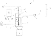
- the single figure represents, purely schematically, a device 1 according to the invention for product gas filtration.
- the device 1 is a product gas stream, which leads through pipes 2 of a wood-gas reactor 3 (only indicated) to the actual filter 4, respectively.
- a clean gas line 5 in which a blower 6 is arranged, leads to a gas conversion machine in the form of a turbine, an internal combustion engine, etc.
- the filter 4 consists essentially of a housing and a separating tray 8, on which several, in the illustrated embodiment, there are two filter cartridges 9 down, projecting towards the uncleaned product gas, are arranged.
- the separating tray 8 and its connection to the housing and the filter cartridges 9 is formed so dense that the product gas coming through the product gas line 2 only through the filter cartridges 9 into the plenum 10 for the clean gas above the dividing tray 8 and from there into the clean gas line. 5 can get.
- the lower portion of the filter 4 is conical or otherwise tapered and leads at its lower end, in the illustrated embodiment without Shut-off, in a dust container 11.
- a shut-off example a rotary valve can be provided, even simple flaps are possible.
- the filter cartridges 9 are, as known from the prior art, via compressed air lines 12 and selectively operable shut-off valves 13 connected to a pressure reservoir P.
- the associated obturator 13 of each considered filter candle is opened and there is a short but violent pressure surge against the direction of flow of the product gas through the filter cartridge through which the filter cake is properly blasted off and, following gravity, down into the dust container 11 passes. After a short time, usually after only a few milliseconds, the obturator 13 is closed again and it begins to build the next filter cake. In this way, with proper design knowledge of the composition of the product gas and clean gas purity requirements to be maintained, the desired purity, over time, can be achieved despite the filter characteristics that fluctuate over time.
- a reservoir 14 is provided for zeolite according to the invention.
- Whose lower end opens into a venturi 15, which, with suitably open shut-off valves 16, by compressed air, coming from a storage vessel P, or a compressor, flows through.
- This compressed air now takes with the passage through the venturi 15 from the reservoir 14 finely ground zeolite and atomized by one or more nozzles 17 into the interior of the filter 4, preferably approximately in the area of the filter cartridges.
- this device is such that always after the blowing off of filter cake from one of the filter cartridges 9, the two shut-off valves 16 are opened briefly, so that compressed air flows through the venturi 15 and thereby takes finely ground zeolite with it.
- This is atomized during injection into the interior of the housing of the filter 4 and preferred with the product gas stream (here the flow resistance is lower because of the missing filter cake than in the (the) other candle (s)) transported to the just cleaned filter cartridge 9, where he their filter surface applies.
- the flow resistance is lower because of the missing filter cake than in the (the) other candle (s) transported to the just cleaned filter cartridge 9, where he their filter surface applies.
- the flow resistance is lower because of the missing filter cake than in the (the) other candle (s) transported to the just cleaned filter cartridge 9, where he their filter surface applies.
- the just cleaned filter cartridge 9 where he their filter surface applies.
- the invention is not limited to the described and illustrated embodiment, but may be variously modified and adapted. Thus, in most cases, a separate start program will be provided in order to bring no uncleaned product gases for further use or in the environment at the beginning of the filtering.
- a separate start program will be provided in order to bring no uncleaned product gases for further use or in the environment at the beginning of the filtering.
- Such additional filter can also be switched on a filter cartridge after blowing until a new filter cake is formed.
- the corresponding features and valves or flaps, etc. are also not shown for reasons of clarity, and because they are not causally linked to the gist of the invention. This also applies to the sensors that operate monitor, in particular the pressure gauges and the flowmeters, which can be closed on the state of the filter cake.
- the inlets for the atomized zeolite are to be increased accordingly, it can be the positions of the individual injection nozzles adapted to the respective filter cartridges and may also be activated individually or in groups. Whether several reservoirs 14 are also provided depends on the individual circumstances and can easily be decided by the person skilled in the art of general gas cleaning with knowledge of the invention and of the application.
- the particle size of the zeolite to be injected is in conventional applications a minimum of 15 ⁇ m and a maximum of 50 ⁇ m.
- the respective product gas composition can be taken into account, by a few experiments with different particle size or particle size distributions, the respective optimum, also depending on the filter cartridges used, can be found.
- the exact specification of the natural or synthetic zeolite used depends on the particular product gas producer and needs no further explanation here.
Abstract
Die Erfindung betrifft ein Produktgasfilter (1) mit einem Gehäuse, dem Produktgas eines Holz-Gasreaktors (3) mittels einer Produktgasleitung (2) zugeführt wird, und von dem Reingas durch eine Reingasleitung (5) abgeführt wird. Um langkettige Kohlenwasserstoffe zumindest im Wesentlichen aus dem Produktgasstrom reduzieren zu können und auch eine hohe Filterleistung zu erzielen ist vorgesehen, dass das Filter (1) durch einen Trennboden (8) gasdicht in zwei Teile geteilt ist, dass die Produktgasleitung (2) in einen, den unteren, Bereich (4) einmündet und die Reingasleitung (5) vom oberen, dem Sammelraum (10) ausgeht, dass am Trennboden (8) zumindest zwei Filterkerzen (9) angeordnet sind, die einzeln mittels Druckluftleitungen (12) mit einer Druckluftquelle (P) verbindbar sind und in den unteren Bereich (4) ragen, und dass ein Zeolithbehälter (14) über eine, mit einer Druckluftquelle (P) verbindbare, Venturidüse (15) und eine absperrbare Leitung mit dem unteren Bereich (4) des Filters (1) verbunden ist.The invention relates to a product gas filter (1) with a housing, the product gas of a wood gas reactor (3) by means of a product gas line (2) is supplied, and is discharged from the clean gas through a clean gas line (5). In order to be able to reduce long-chain hydrocarbons at least substantially from the product gas stream and also to achieve a high filter performance, it is provided that the filter (1) is divided gas-tight into two parts by a separating tray (8) in such a way that the product gas line (2), the lower, region (4) opens and the clean gas line (5) from the upper, the collecting space (10) that at the separating tray (8) at least two filter cartridges (9) are arranged, which individually by means of compressed air lines (12) with a compressed air source ( P) are connectable and in the lower region (4) protrude, and that a zeolite container (14) via a, with a compressed air source (P) connectable Venturi nozzle (15) and a lockable line with the lower portion (4) of the filter ( 1) is connected.
Description
Die Erfindung betrifft eine Vorrichtung zum Reduzieren von langkettigen Kohlenwasserstoffen im Produktgas von Holz-Gasreaktoren entsprechend dem Oberbegriff des Anspruches 1; mit anderen Worten ein Produktgasfilter mit einem Gehäuse, dem Produktgas von einem Holz-Gasreaktor mittels einer Produktgasleitung zugeführt wird.The invention relates to a device for reducing long-chain hydrocarbons in the product gas of wood gas reactors according to the preamble of claim 1; in other words, a product gas filter having a housing to which product gas from a wood gas reactor is supplied by means of a product gas line.
Als langkettige Kohlenwasserstoffe können beispielsweise die bei der Biomassevergasung üblicherweise anfallenden wie: Phenol, Acenaphthylen, Naphtalion, Methylnaphthalin, Phenanthren, Kresol, Biphenyl, Fluren und Anthracen genannt werden. Bei der Holzvergasung wird deren Bildung durch die stets vorhandenen Terpene und auch das Lignin bewirkt.As long-chain hydrocarbons, for example, those commonly used in biomass gasification such as: phenol, acenaphthylene, naphthalene, methylnaphthalene, phenanthrene, cresol, biphenyl, fields and anthracene can be mentioned. In wood gasification, their formation is effected by the ever present terpenes and also the lignin.
Als Reaktoren sind alle im Stand der Technik bekannten zu nennen, somit insbesondere solche mit aufsteigender Vergasung, mit absteigender Vergasung, mit 2 stufiger Vergasung, mit stationärer Wirbelschicht und auch solche mit zirkulierender Wirbelschicht.Reactors are all known in the art, thus in particular those with increasing gasification, with decreasing gasification, with 2-stage gasification, with stationary fluidized bed and also with circulating fluidized bed.
Holz-Gasreaktoren im Sinne der Erfindung produzieren aus Biomasse ein Produktgas, das in der Folge auf unterschiedlichste Weise verwendet werden kann, beispielsweise in einem Blockkraftwerk, in einer Turbine und dergleichen mehr. Dabei ist es notwendig, im Produktgas enthaltene Feststoffe abzuscheiden. Derartige Feststoffe sind bei Gasreaktoren zumeist unverbrannte Kohlenstoffpartikel, doch können in geringen Mengen auch andere Beimengungen enthalten sein. Hier wird sowohl vom jeweiligen Gesetzgeber als auch von den Betreibern zunehmend auf das Entfernen des sogenannten Feinstaubs gedrängt, und es werden derartige, stets strenger werdende Grenzwerte vorgeschrieben.Wood gas reactors according to the invention produce from biomass, a product gas, which can be used in a variety of ways, for example in a block power plant, in a turbine and the like. It is necessary to separate solids contained in the product gas. Such solids are in gas reactors mostly unburned carbon particles, but may be included in small amounts and other admixtures. Here, both the respective legislator and the operators are increasingly urging the removal of so-called fine dust, and such, ever stricter limits are prescribed.
Eine Möglichkeit, diese Feststoffe abzuscheiden besteht in einer klassischen Filterung, wobei die unterschiedlichsten Filter verwendet werden können, es soll nur auf Filterkerzen und Filtersäcke verwiesen werden.One way to separate these solids consists in a classic filtering, with a variety of filters can be used, it should only be referenced to filter cartridges and filter bags.
Eine alternative Technologie zum Filtern ist die Verwendung eines Katalysators, bei dem diese Feststoffpartikel, soweit dies chemisch möglich ist, katalytisch verbrannt werden. Beide Verfahren hatten ihre Vor- und Nachteile.An alternative technology for filtering is the use of a catalyst in which these solid particles are catalytically burned, as far as this is chemically possible. Both methods had their advantages and disadvantages.
Es kommt nun dazu, dass die Gesetzgeber in verschiedenen Ländern nicht nur eine zunehmend bessere Filterung von Produktgasen und Rauchgasen allgemein verlangen sondern auch, als ein Novum, fordern, dass die im Produktgas verbleibenden Anteile an langkettigen Kohlenwasserstoffen reduziert werden müssen. Um langkettige Kohlenwasserstoffe aus der Biomassevergasung zu reduzieren wird zur Zeit höchstes Augenmerk auf den eingesetzten Brennstoff und dessen Stückigkeit gelegt. Verschiedentlich spielt auch der Feuchtigkeitsgehalt des Brennstoffes eine Rolle. Dazu kommt, dass derartige Bestandteile den der Biovergasung nachgeschalteten Aggregaten wie z.B. Motoren, schaden, da sie auskondensieren und zum Verkleben neigen.In addition, lawmakers in various countries not only demand increasingly better filtering of product gases and flue gases in general, but also, as a novelty, demand that the levels of long-chain hydrocarbons remaining in the product gas be reduced. In order to reduce long-chain hydrocarbons from biomass gasification, the focus is currently placed on the fuel used and its bulkiness. Occasionally, the moisture content of the fuel also plays a role. In addition, such components may be added to the gassing downstream aggregates, e.g. Engines, damage as they condense and tend to stick.
Es ist das Ziel der Erfindung, eine derartige Vorrichtung bzw. ein derartiges Verfahren zu schaffen, das in der Lage ist, auch die Vorgaben der Zukunft zu erfüllen und somit insbesondere in der Lage ist, langkettige Kohlenwasserstoffe aus dem Produktgas zumindest weitgehend zu entfernen und bevorzugt in einem den Fein- und Feinststaub abzufiltern.It is the object of the invention to provide such a device or a method which is able to meet the requirements of the future and thus is in particular able to remove long-chain hydrocarbons from the product gas at least largely and preferably to filter out the fine and fine dust in one.
Erfindungsgemäß werden diese Ziele durch die im kennzeichnenden Teil des Anspruches 1 enthaltenen Merkmale erreicht; mit anderen Worten, es wird auf ein vom Produktgasstrom zu durchquerendes Filter bzw. einen Filterkuchen ein Auftrag an feingemahlenen Zeolith aufgebracht, durch den insbesondere langkettige Kohlenwasserstoffe katalytisch über den Zeolithfilterkuchen gecrackt werden und mit ihm aus dem Produktgasstrom ausgebracht werden kann.According to the invention, these objects are achieved by the features contained in the characterizing part of claim 1; in other words, an order of finely ground zeolite is applied to a filter or a filter cake to be traversed by the product gas stream, by which in particular long-chain hydrocarbons are catalytically cracked over the zeolite filter cake and can be discharged from the product gas stream with it.
In einer bevorzugten Ausführungsform weist ein erfindungsgemäßes Produktgasfilter zumindest zwei Filterkerzen auf, durch die das Produktgas strömt, und auf deren Oberfläche die Partikel ausgefiltert werden, was zum Aufbau eines Filterkuchens führt, wobei, wie bei derartigen Filtern bekannt, bei Übersteigen des Druckabfalls des durchfließenden Produktgasstromes über einen vorgegebenen Grenzwert der Filterkuchen abgetrennt und aus dem Filter ausgebracht wird. Erfindungsgemäß wird dabei nach dem Entfernen des Filterkuchens feinvermahlener Zeolith im Bereich der Filterkerze(n) in den Produktgasstrom geblasen, legt sich als Grundlage des Filterkuchens an die Filterkerze an und bildet so eine Schicht oder einen Mantel, wenn auch extrem dünn, der in der Lage ist, die im Produktgasstrom enthaltenen langkettigen Kohlenwasserstoffe zu reduzieren. Mit dem nächsten Abblasen bzw. Absprengen des Filterkuchens wird mit diesem auch der verbrauchte katalytisch wirkende Zeolith ausgebracht.In a preferred embodiment, a product gas filter according to the invention has at least two filter cartridges through which the product gas flows, and on the surface of which the particles are filtered out, resulting in the construction of a filter cake, as known in such filters, when exceeding the pressure drop of the flowing product gas stream separated over a predetermined limit of the filter cake and discharged from the filter. According to the invention is after the Removing the filter cake finely ground zeolite in the area of the filter candle (s) blown into the product gas stream, forms as the basis of the filter cake to the filter candle and forms a layer or a coat, albeit extremely thin, which is capable of that in the product gas stream to reduce contained long-chain hydrocarbons. With the next blowing off or blasting off of the filter cake, the spent catalytically active zeolite is also applied with this filter.
Zeolith ist im Stand der Technik zur Abscheidung von Quecksilber aus Rauchgas fossiler Herkunft verwendet worden, wie in der
Die Erfindung wird im Folgenden anhand einer rein schematischen Darstellung, mit einer einzigen Figur näher erläutert.The invention is explained in more detail below with reference to a purely schematic representation, with a single figure.
Die einzige Figur stellt, rein schematisch, eine erfindungsgemäße Einrichtung 1 zur Produktgasfilterung dar. Wie im technischen Jargon werden auch hier die Gesamtheit des Filters mit allen Umhüllungen, Armaturen, etc. und das Filter an sich oft synonym als "Produktgasfilter" oder kurz "Filter" benannt, da aus dem Zusammenhang die jeweilige Bedeutung zweifelsfrei erschließbar ist. Der Einrichtung 1 wird ein Produktgasstrom, der durch Rohrleitungen 2 von einem Holz-Gasreaktor 3 (nur angedeutet) zum eigentlichen Filter 4 führt, zugeführt. Vom Filter 4 führt eine Reingasleitung 5, in der ein Gebläse 6 angeordnet ist, zu einer Gasumwandlungsmaschine in Form einer Turbine, einer Verbrennungskraftmaschine etc.The single figure represents, purely schematically, a device 1 according to the invention for product gas filtration. As in technical jargon, the entirety of the filter with all enclosures, fittings, etc. and the filter itself are often synonymous as "product gas filter" or "filter "named because the respective meaning can be deduced without doubt from the context. The device 1 is a product gas stream, which leads through
Das Filter 4 besteht im Wesentlichen aus einem Gehäuse und einem Trennboden 8, an dem mehrere, in dargestellten Ausführungsbeispiel sind es zwei, Filterkerzen 9 nach unten, zum ungereinigten Produktgas hin ragend, angeordnet sind. Der Trennboden 8 und seine Verbindung zum Gehäuse und zu den Filterkerzen 9 ist so dicht ausgebildet, dass das durch die Produktgasleitung 2 kommende Produktgas nur durch die Filterkerzen 9 hindurch in den Sammelraum 10 für das Reingas oberhalb des Trennbodens 8 und von dort in die Reingasleitung 5 gelangen kann.The filter 4 consists essentially of a housing and a separating tray 8, on which several, in the illustrated embodiment, there are two
Der untere Bereich des Filters 4 ist konisch oder sich auf andere Weise verjüngend ausgestaltet und führt an seinem unteren Ende, im dargestellten Ausführungsbeispiel ohne Absperrvorrichtung, in einen Staubbehälter 11. Als Absperrorgan kann beispielsweise eine Zellradschleuse vorgesehen werden, auch einfache Klappen sind möglich.The lower portion of the filter 4 is conical or otherwise tapered and leads at its lower end, in the illustrated embodiment without Shut-off, in a dust container 11. As a shut-off example, a rotary valve can be provided, even simple flaps are possible.
Die Filterkerzen 9 sind, wie aus dem Stand der Technik bekannt, über Druckluftleitungen 12 und selektiv betätigbare Absperrorgane 13 mit einem Druckreservoir P verbunden.The
Die bisher beschriebene Vorrichtung entspricht durchaus konventionellen Produktgasfiltern, deren Betrieb, da er dem des Standes der Technik entspricht, nur kurz dargestellt werden soll:
- Im Normalbetrieb (Anfahrbetrieb und Notbetrieb werden hier nicht beschrieben) strömt das Produktgas von Holz-Gasreaktor 3 durch die
Produktgasleitung 2 in den Filter 4, von dort durch dieFilterkerzen 9 in den Sammelraum 10, von dort durch die Reingasleitung 5 und das eventuell vorgesehene oder auch nicht vorgesehene Gebläse 6 in die Gasumwandlungseinheit. Dabei wird beim Durchtritt durch die Oberfläche derFilterkerzen 9 festes Material aus dem Produktgasstrom abgefiltert, es bildet sich ein Filterkuchen aus. Dieser Filterkuchen verbessert einerseits die Filtereigenschaften, andererseits wird durch den zunehmenden Aufbau des Filterkuchens der Druckabfall an denFilterkerzen 9 erhöht und so der Durchfluss beeinträchtigt.
- In normal operation (starting operation and emergency operation are not described here) flows the product gas from wood gas reactor 3 through the
product gas line 2 in the filter 4, from there through thefilter cartridges 9 in the plenum 10, from there through the clean gas line 5 and possibly provided or also not provided blower 6 in the gas conversion unit. In this case, when passing through the surface of thefilter cartridges 9 solid material from the product gas stream is filtered off, it forms a filter cake. On the one hand, this filter cake improves the filter properties; on the other hand, the increasing build-up of the filter cake increases the pressure drop across thefilter cartridges 9 and thus impairs the flow.
Wenn vorgegebene Grenzwerte des Druckabfalls erreicht werden, die dazu notwendigen Sensoren werden weiter unten beschrieben, so wird das zugehörige Absperrorgan 13 der jeweils betrachteten Filterkerze geöffnet und es erfolgt ein kurzer, aber heftiger Druckstoß entgegen der Durchflussrichtung des Produktgases durch die Filterkerze, durch die der Filterkuchen richtiggehend abgesprengt wird und, der Schwerkraft folgend, nach unten in den Staubbehälter 11 gelangt. Bereits nach kurzer Zeit, meist nach nur wenigen Millisekunden, wird das Absperrorgan 13 wieder geschlossen und es beginnt sich der nächste Filterkuchen aufzubauen. Es kann auf diese Weise bei richtiger Auslegung in Kenntnis der Zusammensetzung des Produktgases und der einzuhaltenden Reinheitsvorschriften für das Reingas trotz der über der Zeit fluktuierenden Filtereigenschaften die gewünschte Reinheit, über die Zeit betrachtet, erreicht werden.If predetermined limits of the pressure drop are achieved, the necessary sensors are described below, the associated obturator 13 of each considered filter candle is opened and there is a short but violent pressure surge against the direction of flow of the product gas through the filter cartridge through which the filter cake is properly blasted off and, following gravity, down into the dust container 11 passes. After a short time, usually after only a few milliseconds, the obturator 13 is closed again and it begins to build the next filter cake. In this way, with proper design knowledge of the composition of the product gas and clean gas purity requirements to be maintained, the desired purity, over time, can be achieved despite the filter characteristics that fluctuate over time.
Um nun einerseits auch die feinsten Feinstaubfraktionen besser abscheiden zu können und andererseits, darüber hinaus und erfindungsgemäß, auch langkettige Kohlenwasserstoffe zu reduzieren, ist erfindungsgemäß ein Vorratsbehälter 14 für Zeolithmaterial vorgesehen. Dessen unteres Ende mündet in eine Venturidüse 15, die, bei passend geöffneten Absperrorganen 16, von Druckluft, kommend aus einem Vorratsgefäß P, oder einem Kompressor, durchströmt wird. Diese Druckluft nimmt nun beim Durchtritt durch die Venturidüse 15 aus dem Vorratsbehälter 14 fein vermahlenen Zeolith mit und zerstäubt ihn durch eine oder mehrere Düsen 17 ins Innere des Filters 4, bevorzugt etwa im Bereich der Filterkerzen 9.In order to better deposit on the one hand even the finest particulate matter fractions and on the other hand, beyond and according to the invention, to reduce long-chain hydrocarbons, a reservoir 14 is provided for zeolite according to the invention. Whose lower end opens into a venturi 15, which, with suitably open shut-off
Betrieben wird diese Vorrichtung derart, dass stets nach dem Absprengen von Filterkuchen von einer der Filterkerzen 9 die beiden Absperrorgane 16 kurz geöffnet werden, sodass Druckluft durch die Venturidüse 15 strömt und dabei fein vermahlenen Zeolith mit sich nimmt. Dieser wird beim Einblasen ins Innere des Gehäuses des Filters 4 zerstäubt und mit dem Produktgasstrom bevorzugt (hier ist der Strömungswiderstand wegen des fehlenden Filterkuchens geringer als in der (den) anderen Kerze(n)) zur gerade gereinigten Filterkerze 9 transportiert, wo er sich an deren Filteroberfläche anlegt. So bildet er im Wesentlichen die erste Schicht und damit die Grundlage für den kommenden aufzubauenden Filterkuchen. Beim Durchtritt durch diesen Filterkuchen und schlussendlich die, wenn auch dünne Schichte, Zeolith, werden langkettige Kohlenwasserstoffe reduziert und der verbrauchte katalytische Zeolith wird beim nächsten Absprengen des Filterkuchens in den Staubbehälter 11 ausgebracht.Operated, this device is such that always after the blowing off of filter cake from one of the
Die Erfindung ist nicht auf die beschriebene und dargestellte Ausführungsform beschränkt, sondern kann verschiedentlich abgeändert und adaptiert werden. So wird in den meisten Fällen ein eigenes Startprogramm vorgesehen sein, um schon zu Beginn des Filterns keine ungereinigten Produktgase zur weiteren Verwendung bzw. in die Umgebung zu bringen. Dafür gibt es zahlreiche Vorbilder im Stand der Technik, die in Kenntnis der Erfindung leicht mit dieser zu kombinieren sind. Derartige zusätzliche Filter können auch einer Filterkerze nach dem Abblasen zugeschaltet werden, bis ein neuer Filterkuchen ausgebildet ist. Die entsprechenden Züge und Ventile bzw. Klappen, etc. sind aus Gründen der Übersichtlichkeit, und weil sie mit dem Kern der Erfindung nicht ursächlich verknüpft sind, ebenfalls nicht dargestellt. Dies gilt auch für die Sensoren, die den Betrieb überwachen, insbesondere die Druckmessgeräte und die Durchflussmeßgeräte, durch die auf den Zustand der Filterkuchen geschlossen werden kann.The invention is not limited to the described and illustrated embodiment, but may be variously modified and adapted. Thus, in most cases, a separate start program will be provided in order to bring no uncleaned product gases for further use or in the environment at the beginning of the filtering. There are numerous models in the art, which are easy to combine with this knowledge of the invention. Such additional filter can also be switched on a filter cartridge after blowing until a new filter cake is formed. The corresponding features and valves or flaps, etc. are also not shown for reasons of clarity, and because they are not causally linked to the gist of the invention. This also applies to the sensors that operate monitor, in particular the pressure gauges and the flowmeters, which can be closed on the state of the filter cake.
Im Falle des Vorsehens mehrerer Filterkerzen sind die Einlässe für den zerstäubten Zeolith entsprechend zu vermehren, es können die Lagen der einzelnen Einblasdüsen den jeweiligen Filterkerzen angepasst werden und unter Umständen auch einzeln oder in Gruppen aktiviert werden. Ob dabei auch mehrere Vorratsbehälter 14 vorgesehen werden, hängt von den Einzelumständen ab und ist vom Fachmann auf dem Gebiet der allgemeinen Gasreinigung in Kenntnis der Erfindung und des Anwendungsfalles leicht zu entscheiden.In the case of providing multiple filter cartridges, the inlets for the atomized zeolite are to be increased accordingly, it can be the positions of the individual injection nozzles adapted to the respective filter cartridges and may also be activated individually or in groups. Whether several reservoirs 14 are also provided depends on the individual circumstances and can easily be decided by the person skilled in the art of general gas cleaning with knowledge of the invention and of the application.
Die verwendbaren Materialien sind die gleichen wie im Stand der Technik, es ändert sich durch die Erfindung daran nichts, sodass es nicht notwendig erscheint, hier darauf einzugehen. Die Steuerung der Anlage entspricht, mit Ausnahme der erfindungsgemäß zu betreibenden Filterkerzen und der Zeolitheinblasung, ebenfalls dem Stand der Technik, diese beiden erfindungsgemäßen Steuerungen sind oben beschrieben worden, Details können anhand weniger, einfacher Tests eruiert werden.The materials that can be used are the same as in the prior art, it changes nothing by the invention, so it does not seem necessary to address it here. The control of the system corresponds, with the exception of the present invention to be operated filter cartridges and Zeolitheinblasung, also the prior art, these two controls according to the invention have been described above, details can be eruiert using less simple tests.
Die Korngröße des einzublasenden Zeoliths beträgt in üblichen Anwendungsfällen minimal 15µm und maximal 50µm. Durch die Modifikation des Zeoliths kann die jeweilige Produktgaszusammensetzung berücksichtigt werden, durch einige wenige Versuche mit unterschiedlicher Korngröße bzw. Korngrößenverteilungen kann das jeweilige Optimum, auch in Abhängigkeit der verwendeten Filterkerzen, gefunden werden. Die genaue Spezifikation des eingesetzten natürlichen bzw. synthetischen Zeoliths ist vom jeweiligen Produktgaserzeuger abhängig und bedarf hier keiner näheren Erläuterung.The particle size of the zeolite to be injected is in conventional applications a minimum of 15 μm and a maximum of 50 μm. By modifying the zeolite, the respective product gas composition can be taken into account, by a few experiments with different particle size or particle size distributions, the respective optimum, also depending on the filter cartridges used, can be found. The exact specification of the natural or synthetic zeolite used depends on the particular product gas producer and needs no further explanation here.
Es soll noch darauf hingewiesen werden, dass in der Beschreibung und den Ansprüchen Angaben wie "großteils" bei der Zusammensetzung von Materialien über 50 Gew.-%, bevorzugt über 80 Gew.-% und besonders bevorzugt über 95 Gew.-% bedeuten; dass "unterer Bereich" eines Reaktors, Filters, Bauwerks, oder einer Vorrichtung oder, ganz allgemein, eines Gegenstandes, die untere Hälfte und insbesondere das untere Viertel der Gesamthöhe bedeutet, "unterster Bereich" das unterste Viertel und insbesondere einen noch kleineren Teil; während "mittlerer Bereich" das mittlere Drittel der Gesamthöhe meint. All diese Angaben haben ihre im Zusammenhang mit dem betrachteten Gegenstand landläufige Bedeutung, angewandt auf dessen bestimmungsgemäße Position und Lage.It should also be pointed out that in the description and the claims information such as "largely" in the composition of materials over 50 wt .-%, preferably above 80 wt .-% and particularly preferably above 95 wt .-% mean; that "lower area" of a reactor, filter, structure, or device, or, more generally, an object, means the lower half and especially the lower quarter of the total height, "lowest area" means the lowest quarter and in particular an even smaller portion; while "middle range" is the middle third of the total height means. All this information has its common meaning in relation to the subject matter considered, applied to its intended position and location.
In der Beschreibung und den Ansprüchen bedeutet "im Wesentlichen" eine Abweichung von bis zu 10 % des angegebenen Wertes, wenn es physikalisch möglich ist, sowohl nach unten als auch nach oben, ansonsten nur in die sinnvolle Richtung, bei Gradangaben (Winkel und Temperatur) sind damit ± 10° gemeint.
Claims (10)
Priority Applications (15)
| Application Number | Priority Date | Filing Date | Title |
|---|---|---|---|
| ES16199125T ES2805205T3 (en) | 2016-11-16 | 2016-11-16 | Product gas filter for wood gasification reactor exhaust gases comprising filter candles and a zeolite injection |
| PL16199125T PL3323495T3 (en) | 2016-11-16 | 2016-11-16 | Product gas filter for exhaust gases of wood-gasification reactors comprising filter candles and a zeolite injection |
| SI201630833T SI3323495T1 (en) | 2016-11-16 | 2016-11-16 | Product gas filter for exhaust gases of wood-gasification reactors comprising filter candles and a zeolite injection |
| RS20200822A RS60530B1 (en) | 2016-11-16 | 2016-11-16 | Product gas filter for exhaust gases of wood-gasification reactors comprising filter candles and a zeolite injection |
| DK16199125.2T DK3323495T3 (en) | 2016-11-16 | 2016-11-16 | Product gas filter for effluent gases from wood gas reactors, comprehensive filter cartridges and a zeolite injection |
| EP16199125.2A EP3323495B1 (en) | 2016-11-16 | 2016-11-16 | Product gas filter for exhaust gases of wood-gasification reactors comprising filter candles and a zeolite injection |
| LTEP16199125.2T LT3323495T (en) | 2016-11-16 | 2016-11-16 | Product gas filter for exhaust gases of wood-gasification reactors comprising filter candles and a zeolite injection |
| KR1020197013934A KR102332864B1 (en) | 2016-11-16 | 2017-11-10 | Product gas filter comprising candle filters and a zeolite source |
| CN201780071108.1A CN110167656B (en) | 2016-11-16 | 2017-11-10 | Product gas filter comprising filter candles and a zeolite supply |
| CA3044095A CA3044095C (en) | 2016-11-16 | 2017-11-10 | Product gas filter |
| US16/461,140 US11260332B2 (en) | 2016-11-16 | 2017-11-10 | Product gas filter |
| JP2019547178A JP2019537661A (en) | 2016-11-16 | 2017-11-10 | Product gas filter with filter candle and zeolite supply |
| PCT/EP2017/078908 WO2018091371A1 (en) | 2016-11-16 | 2017-11-10 | Product gas filter comprising candle filters and a zeolite supply |
| EA201792292A EA034793B1 (en) | 2016-11-16 | 2017-11-15 | Product gas filter |
| HRP20201097TT HRP20201097T1 (en) | 2016-11-16 | 2020-07-14 | Product gas filter for exhaust gases of wood-gasification reactors comprising filter candles and a zeolite injection |
Applications Claiming Priority (1)
| Application Number | Priority Date | Filing Date | Title |
|---|---|---|---|
| EP16199125.2A EP3323495B1 (en) | 2016-11-16 | 2016-11-16 | Product gas filter for exhaust gases of wood-gasification reactors comprising filter candles and a zeolite injection |
Publications (2)
| Publication Number | Publication Date |
|---|---|
| EP3323495A1 true EP3323495A1 (en) | 2018-05-23 |
| EP3323495B1 EP3323495B1 (en) | 2020-04-29 |
Family
ID=57348487
Family Applications (1)
| Application Number | Title | Priority Date | Filing Date |
|---|---|---|---|
| EP16199125.2A Active EP3323495B1 (en) | 2016-11-16 | 2016-11-16 | Product gas filter for exhaust gases of wood-gasification reactors comprising filter candles and a zeolite injection |
Country Status (15)
| Country | Link |
|---|---|
| US (1) | US11260332B2 (en) |
| EP (1) | EP3323495B1 (en) |
| JP (1) | JP2019537661A (en) |
| KR (1) | KR102332864B1 (en) |
| CN (1) | CN110167656B (en) |
| CA (1) | CA3044095C (en) |
| DK (1) | DK3323495T3 (en) |
| EA (1) | EA034793B1 (en) |
| ES (1) | ES2805205T3 (en) |
| HR (1) | HRP20201097T1 (en) |
| LT (1) | LT3323495T (en) |
| PL (1) | PL3323495T3 (en) |
| RS (1) | RS60530B1 (en) |
| SI (1) | SI3323495T1 (en) |
| WO (1) | WO2018091371A1 (en) |
Families Citing this family (1)
| Publication number | Priority date | Publication date | Assignee | Title |
|---|---|---|---|---|
| GB201911704D0 (en) * | 2019-08-15 | 2019-10-02 | Johnson Matthey Plc | Treatment of particulate filters |
Citations (6)
| Publication number | Priority date | Publication date | Assignee | Title |
|---|---|---|---|---|
| US5505766A (en) | 1994-07-12 | 1996-04-09 | Electric Power Research, Inc. | Method for removing pollutants from a combustor flue gas and system for same |
| JP2005028294A (en) * | 2003-07-04 | 2005-02-03 | Kurita Water Ind Ltd | Flue gas treatment method |
| EP1870444A2 (en) * | 2006-06-20 | 2007-12-26 | Walter Kuntschar | Method for cleaning gases from a woodgas powered vehicle and filter therefore |
| WO2008089503A1 (en) * | 2007-01-24 | 2008-07-31 | Urbas Maschinenfabrik Gesellschaft M.B.H. | Wood gasification system |
| WO2010034791A1 (en) * | 2008-09-26 | 2010-04-01 | Siemens Vai Metals Technologies Gmbh & Co | Method and device for dry dust removal and cleaning of gas produced during iron production or coal gasification |
| EP3067407A1 (en) * | 2015-03-12 | 2016-09-14 | Glock Gaston | System and method for gasification of carbonaceous material |
Family Cites Families (22)
| Publication number | Priority date | Publication date | Assignee | Title |
|---|---|---|---|---|
| US2975000A (en) * | 1959-11-12 | 1961-03-14 | United States Steel Corp | Apparatus for transferring fluidized solids |
| DE3709671A1 (en) * | 1987-03-24 | 1988-10-06 | Man Technologie Gmbh | Particle filter |
| DE4226145A1 (en) * | 1992-08-07 | 1994-02-10 | Babcock Energie Umwelt | Process for monitoring filter elements |
| US5636240A (en) * | 1994-11-16 | 1997-06-03 | Industrial Technology Research Institute | Air pollution control process and apparatus for glass furnace |
| DE19527311A1 (en) * | 1995-07-26 | 1997-01-30 | Lurgi Lentjes Babcock Energie | Method and device for cleaning dust-laden gas |
| DE19917165C2 (en) * | 1999-04-16 | 2001-02-08 | Karlsruhe Forschzent | Process for cleaning tubular filter elements and device for carrying out the process |
| WO2000071231A1 (en) * | 1999-05-21 | 2000-11-30 | Shell Internationale Research Maatschappij B.V. | Apparatus and process for removing solid particles from gases |
| JP2001058117A (en) * | 1999-08-23 | 2001-03-06 | Chugai Ro Co Ltd | Method for treating exhaust gas and apparatus thereof |
| US6863868B1 (en) * | 2000-09-29 | 2005-03-08 | Siemens Westinghouse Power Corporation | Catalytically enhanced filtration apparatus |
| US20040261376A1 (en) * | 2003-06-26 | 2004-12-30 | Morgan Lee Pendleton | Pleated air filter with reverse pulsating air flow cleaning |
| JP2007238670A (en) * | 2006-03-06 | 2007-09-20 | Mitsubishi Heavy Ind Ltd | Gas purifying equipment and process, gasification system, and gasification/power generation system |
| AT507524B1 (en) * | 2008-10-23 | 2010-10-15 | Siemens Vai Metals Tech Gmbh | METHOD AND DEVICE FOR REMOVING PARTICULATE SOLIDS FROM A GASSTROM |
| CN201664555U (en) * | 2010-02-09 | 2010-12-08 | 中山市君禾机电设备有限公司 | Filter cartridge component and dust collector |
| GB2479362B (en) * | 2010-04-07 | 2012-07-04 | Rifat A Chalabi | Improvements in gas treatment |
| CN201921616U (en) * | 2010-12-07 | 2011-08-10 | 上海蓝科石油化工有限公司 | Cyclone dust removal device for high-temperature high-concentration gas |
| US8329125B2 (en) * | 2011-04-27 | 2012-12-11 | Primex Process Specialists, Inc. | Flue gas recirculation system |
| WO2013145318A1 (en) * | 2012-03-30 | 2013-10-03 | イビデン株式会社 | Honeycomb filter and production method for honeycomb filter |
| CN102698526B (en) * | 2012-06-20 | 2015-04-08 | 浙江吉天环保科技有限公司 | Internal filtering dust filtering equipment |
| CN103785243A (en) * | 2012-10-31 | 2014-05-14 | 溧阳市众星环保机械有限公司 | Online dust removal pulse bag dust collector |
| JP5397967B1 (en) * | 2013-03-29 | 2014-01-22 | 株式会社プランテック | Filter cloth regeneration method and bag filter device |
| US20150336041A1 (en) * | 2014-05-21 | 2015-11-26 | Bha Altair, Llc | Segmented Filter Assembly |
| CN205007773U (en) * | 2015-08-11 | 2016-02-03 | 南京中电环保科技有限公司 | High temperature gas dedusting device |
-
2016
- 2016-11-16 EP EP16199125.2A patent/EP3323495B1/en active Active
- 2016-11-16 ES ES16199125T patent/ES2805205T3/en active Active
- 2016-11-16 SI SI201630833T patent/SI3323495T1/en unknown
- 2016-11-16 RS RS20200822A patent/RS60530B1/en unknown
- 2016-11-16 LT LTEP16199125.2T patent/LT3323495T/en unknown
- 2016-11-16 PL PL16199125T patent/PL3323495T3/en unknown
- 2016-11-16 DK DK16199125.2T patent/DK3323495T3/en active
-
2017
- 2017-11-10 KR KR1020197013934A patent/KR102332864B1/en active IP Right Grant
- 2017-11-10 CN CN201780071108.1A patent/CN110167656B/en active Active
- 2017-11-10 WO PCT/EP2017/078908 patent/WO2018091371A1/en active Application Filing
- 2017-11-10 US US16/461,140 patent/US11260332B2/en active Active
- 2017-11-10 CA CA3044095A patent/CA3044095C/en active Active
- 2017-11-10 JP JP2019547178A patent/JP2019537661A/en active Pending
- 2017-11-15 EA EA201792292A patent/EA034793B1/en unknown
-
2020
- 2020-07-14 HR HRP20201097TT patent/HRP20201097T1/en unknown
Patent Citations (6)
| Publication number | Priority date | Publication date | Assignee | Title |
|---|---|---|---|---|
| US5505766A (en) | 1994-07-12 | 1996-04-09 | Electric Power Research, Inc. | Method for removing pollutants from a combustor flue gas and system for same |
| JP2005028294A (en) * | 2003-07-04 | 2005-02-03 | Kurita Water Ind Ltd | Flue gas treatment method |
| EP1870444A2 (en) * | 2006-06-20 | 2007-12-26 | Walter Kuntschar | Method for cleaning gases from a woodgas powered vehicle and filter therefore |
| WO2008089503A1 (en) * | 2007-01-24 | 2008-07-31 | Urbas Maschinenfabrik Gesellschaft M.B.H. | Wood gasification system |
| WO2010034791A1 (en) * | 2008-09-26 | 2010-04-01 | Siemens Vai Metals Technologies Gmbh & Co | Method and device for dry dust removal and cleaning of gas produced during iron production or coal gasification |
| EP3067407A1 (en) * | 2015-03-12 | 2016-09-14 | Glock Gaston | System and method for gasification of carbonaceous material |
Also Published As
| Publication number | Publication date |
|---|---|
| CN110167656B (en) | 2022-10-04 |
| EA034793B1 (en) | 2020-03-23 |
| JP2019537661A (en) | 2019-12-26 |
| WO2018091371A1 (en) | 2018-05-24 |
| US20190366254A1 (en) | 2019-12-05 |
| PL3323495T3 (en) | 2020-09-21 |
| EA201792292A1 (en) | 2018-07-31 |
| CA3044095C (en) | 2023-08-29 |
| KR102332864B1 (en) | 2021-12-01 |
| LT3323495T (en) | 2020-08-10 |
| CN110167656A (en) | 2019-08-23 |
| EP3323495B1 (en) | 2020-04-29 |
| SI3323495T1 (en) | 2020-08-31 |
| DK3323495T3 (en) | 2020-07-27 |
| ES2805205T3 (en) | 2021-02-11 |
| US11260332B2 (en) | 2022-03-01 |
| RS60530B1 (en) | 2020-08-31 |
| KR20190074289A (en) | 2019-06-27 |
| HRP20201097T1 (en) | 2020-11-13 |
| CA3044095A1 (en) | 2018-05-24 |
Similar Documents
| Publication | Publication Date | Title |
|---|---|---|
| DE1607694C3 (en) | Plant for the separation of solids from aerosols | |
| EP1404434B1 (en) | Method and device for cleaning filters for dust-laden waste gases | |
| DE2652510A1 (en) | DEVICE FOR DELIVERING PARTICLES ENTITLED IN GAS | |
| EP4065252A1 (en) | Method for intermittently cleaning a filter, and filter device for a metal printing device | |
| DE60014627T2 (en) | DEVICE AND METHOD FOR REMOVING SOLID PARTICLES FROM GASES | |
| DE3408627A1 (en) | DEVICE FOR DEDUSTING HOT GASES | |
| DE4315893A1 (en) | Method and device for regenerating foundry sand | |
| EP3323495A1 (en) | Product gas filter comprising filter candles and a zeolite injection | |
| DE102011052788A1 (en) | Process and apparatus for purifying exhaust gases | |
| WO2010086104A1 (en) | Method for discharging the dust arising during operation of a dedusting system for raw gas | |
| DE10002584B4 (en) | Method and device for filtering gases | |
| EP0191718A1 (en) | Process for cleaning filter elements | |
| EP0274037A1 (en) | Process and device for the separation of particles | |
| DE2848315C3 (en) | Deduster | |
| DE2254162A1 (en) | Dust separation from exhaust gases - continuous renewal of filter medium in filtration zone and continuous removal of dusty medium | |
| DE10126048B4 (en) | Device for cleaning dust-laden raw gases | |
| DE202007019503U1 (en) | Combined gas purification system | |
| DE202018102501U1 (en) | Tandem filter with dedusting | |
| DE2852164C2 (en) | Method and device for operating a hot gas generator within a mill-drying plant | |
| DE2433852A1 (en) | PROCEDURE FOR CONDITIONING DUST-LOADED HOT EXHAUST GAS | |
| DE2625275C3 (en) | System for the separation of gaseous hydrocarbons and radioactive iodine isotopes from exhaust air | |
| DE19633830C2 (en) | Cooling device based on the evaporation principle for hot, dusty gases | |
| EP0422709B1 (en) | Process for the removal of dust from gases | |
| DE3205720C2 (en) | ||
| DE3102403A1 (en) | FLUID CLEANING SYSTEM |
Legal Events
| Date | Code | Title | Description |
|---|---|---|---|
| PUAI | Public reference made under article 153(3) epc to a published international application that has entered the european phase |
Free format text: ORIGINAL CODE: 0009012 |
|
| STAA | Information on the status of an ep patent application or granted ep patent |
Free format text: STATUS: THE APPLICATION HAS BEEN PUBLISHED |
|
| AK | Designated contracting states |
Kind code of ref document: A1 Designated state(s): AL AT BE BG CH CY CZ DE DK EE ES FI FR GB GR HR HU IE IS IT LI LT LU LV MC MK MT NL NO PL PT RO RS SE SI SK SM TR |
|
| AX | Request for extension of the european patent |
Extension state: BA ME |
|
| STAA | Information on the status of an ep patent application or granted ep patent |
Free format text: STATUS: REQUEST FOR EXAMINATION WAS MADE |
|
| 17P | Request for examination filed |
Effective date: 20181123 |
|
| RAV | Requested validation state of the european patent: fee paid |
Extension state: MD Effective date: 20181123 Extension state: MA Effective date: 20181123 |
|
| RAX | Requested extension states of the european patent have changed |
Extension state: ME Payment date: 20181123 Extension state: BA Payment date: 20181123 |
|
| RBV | Designated contracting states (corrected) |
Designated state(s): AL AT BE BG CH CY CZ DE DK EE ES FI FR GB GR HR HU IE IS IT LI LT LU LV MC MK MT NL NO PL PT RO RS SE SI SK SM TR |
|
| RAP1 | Party data changed (applicant data changed or rights of an application transferred) |
Owner name: GLOCK HEALTH, SCIENCE AND RESEARCH GMBH |
|
| RIN1 | Information on inventor provided before grant (corrected) |
Inventor name: GLOCK, GASTON |
|
| GRAJ | Information related to disapproval of communication of intention to grant by the applicant or resumption of examination proceedings by the epo deleted |
Free format text: ORIGINAL CODE: EPIDOSDIGR1 |
|
| GRAP | Despatch of communication of intention to grant a patent |
Free format text: ORIGINAL CODE: EPIDOSNIGR1 |
|
| GRAP | Despatch of communication of intention to grant a patent |
Free format text: ORIGINAL CODE: EPIDOSNIGR1 |
|
| STAA | Information on the status of an ep patent application or granted ep patent |
Free format text: STATUS: GRANT OF PATENT IS INTENDED |
|
| INTG | Intention to grant announced |
Effective date: 20191129 |
|
| INTG | Intention to grant announced |
Effective date: 20191206 |
|
| GRAS | Grant fee paid |
Free format text: ORIGINAL CODE: EPIDOSNIGR3 |
|
| GRAA | (expected) grant |
Free format text: ORIGINAL CODE: 0009210 |
|
| STAA | Information on the status of an ep patent application or granted ep patent |
Free format text: STATUS: THE PATENT HAS BEEN GRANTED |
|
| AK | Designated contracting states |
Kind code of ref document: B1 Designated state(s): AL AT BE BG CH CY CZ DE DK EE ES FI FR GB GR HR HU IE IS IT LI LT LU LV MC MK MT NL NO PL PT RO RS SE SI SK SM TR |
|
| REG | Reference to a national code |
Ref country code: GB Ref legal event code: FG4D Free format text: NOT ENGLISH |
|
| REG | Reference to a national code |
Ref country code: CH Ref legal event code: EP |
|
| REG | Reference to a national code |
Ref country code: AT Ref legal event code: REF Ref document number: 1262446 Country of ref document: AT Kind code of ref document: T Effective date: 20200515 |
|
| REG | Reference to a national code |
Ref country code: DE Ref legal event code: R096 Ref document number: 502016009738 Country of ref document: DE |
|
| REG | Reference to a national code |
Ref country code: IE Ref legal event code: FG4D Free format text: LANGUAGE OF EP DOCUMENT: GERMAN |
|
| REG | Reference to a national code |
Ref country code: CH Ref legal event code: NV Representative=s name: HEPP WENGER RYFFEL AG, CH |
|
| REG | Reference to a national code |
Ref country code: FI Ref legal event code: FGE |
|
| REG | Reference to a national code |
Ref country code: HR Ref legal event code: TUEP Ref document number: P20201097T Country of ref document: HR |
|
| REG | Reference to a national code |
Ref country code: DK Ref legal event code: T3 Effective date: 20200720 |
|
| REG | Reference to a national code |
Ref country code: NL Ref legal event code: FP |
|
| REG | Reference to a national code |
Ref country code: SE Ref legal event code: TRGR |
|
| REG | Reference to a national code |
Ref country code: NO Ref legal event code: T2 Effective date: 20200429 |
|
| REG | Reference to a national code |
Ref country code: SK Ref legal event code: T3 Ref document number: E 34727 Country of ref document: SK |
|
| REG | Reference to a national code |
Ref country code: EE Ref legal event code: FG4A Ref document number: E019557 Country of ref document: EE Effective date: 20200729 |
|
| PG25 | Lapsed in a contracting state [announced via postgrant information from national office to epo] |
Ref country code: PT Free format text: LAPSE BECAUSE OF FAILURE TO SUBMIT A TRANSLATION OF THE DESCRIPTION OR TO PAY THE FEE WITHIN THE PRESCRIBED TIME-LIMIT Effective date: 20200831 Ref country code: GR Free format text: LAPSE BECAUSE OF FAILURE TO SUBMIT A TRANSLATION OF THE DESCRIPTION OR TO PAY THE FEE WITHIN THE PRESCRIBED TIME-LIMIT Effective date: 20200730 Ref country code: IS Free format text: LAPSE BECAUSE OF FAILURE TO SUBMIT A TRANSLATION OF THE DESCRIPTION OR TO PAY THE FEE WITHIN THE PRESCRIBED TIME-LIMIT Effective date: 20200829 |
|
| REG | Reference to a national code |
Ref country code: HR Ref legal event code: T1PR Ref document number: P20201097 Country of ref document: HR |
|
| REG | Reference to a national code |
Ref country code: HR Ref legal event code: ODRP Ref document number: P20201097 Country of ref document: HR Payment date: 20201111 Year of fee payment: 5 |
|
| PG25 | Lapsed in a contracting state [announced via postgrant information from national office to epo] |
Ref country code: BG Free format text: LAPSE BECAUSE OF FAILURE TO SUBMIT A TRANSLATION OF THE DESCRIPTION OR TO PAY THE FEE WITHIN THE PRESCRIBED TIME-LIMIT Effective date: 20200729 |
|
| PG25 | Lapsed in a contracting state [announced via postgrant information from national office to epo] |
Ref country code: AL Free format text: LAPSE BECAUSE OF FAILURE TO SUBMIT A TRANSLATION OF THE DESCRIPTION OR TO PAY THE FEE WITHIN THE PRESCRIBED TIME-LIMIT Effective date: 20200429 |
|
| PG25 | Lapsed in a contracting state [announced via postgrant information from national office to epo] |
Ref country code: SM Free format text: LAPSE BECAUSE OF FAILURE TO SUBMIT A TRANSLATION OF THE DESCRIPTION OR TO PAY THE FEE WITHIN THE PRESCRIBED TIME-LIMIT Effective date: 20200429 |
|
| REG | Reference to a national code |
Ref country code: DE Ref legal event code: R097 Ref document number: 502016009738 Country of ref document: DE |
|
| REG | Reference to a national code |
Ref country code: ES Ref legal event code: FG2A Ref document number: 2805205 Country of ref document: ES Kind code of ref document: T3 Effective date: 20210211 |
|
| PLBE | No opposition filed within time limit |
Free format text: ORIGINAL CODE: 0009261 |
|
| STAA | Information on the status of an ep patent application or granted ep patent |
Free format text: STATUS: NO OPPOSITION FILED WITHIN TIME LIMIT |
|
| 26N | No opposition filed |
Effective date: 20210201 |
|
| PG25 | Lapsed in a contracting state [announced via postgrant information from national office to epo] |
Ref country code: MC Free format text: LAPSE BECAUSE OF FAILURE TO SUBMIT A TRANSLATION OF THE DESCRIPTION OR TO PAY THE FEE WITHIN THE PRESCRIBED TIME-LIMIT Effective date: 20200429 |
|
| PG25 | Lapsed in a contracting state [announced via postgrant information from national office to epo] |
Ref country code: LU Free format text: LAPSE BECAUSE OF NON-PAYMENT OF DUE FEES Effective date: 20201116 |
|
| REG | Reference to a national code |
Ref country code: BE Ref legal event code: MM Effective date: 20201130 |
|
| REG | Reference to a national code |
Ref country code: HR Ref legal event code: ODRP Ref document number: P20201097 Country of ref document: HR Payment date: 20211109 Year of fee payment: 6 |
|
| PG25 | Lapsed in a contracting state [announced via postgrant information from national office to epo] |
Ref country code: TR Free format text: LAPSE BECAUSE OF FAILURE TO SUBMIT A TRANSLATION OF THE DESCRIPTION OR TO PAY THE FEE WITHIN THE PRESCRIBED TIME-LIMIT Effective date: 20200429 Ref country code: MT Free format text: LAPSE BECAUSE OF FAILURE TO SUBMIT A TRANSLATION OF THE DESCRIPTION OR TO PAY THE FEE WITHIN THE PRESCRIBED TIME-LIMIT Effective date: 20200429 Ref country code: CY Free format text: LAPSE BECAUSE OF FAILURE TO SUBMIT A TRANSLATION OF THE DESCRIPTION OR TO PAY THE FEE WITHIN THE PRESCRIBED TIME-LIMIT Effective date: 20200429 |
|
| PG25 | Lapsed in a contracting state [announced via postgrant information from national office to epo] |
Ref country code: MK Free format text: LAPSE BECAUSE OF FAILURE TO SUBMIT A TRANSLATION OF THE DESCRIPTION OR TO PAY THE FEE WITHIN THE PRESCRIBED TIME-LIMIT Effective date: 20200429 |
|
| PG25 | Lapsed in a contracting state [announced via postgrant information from national office to epo] |
Ref country code: BE Free format text: LAPSE BECAUSE OF NON-PAYMENT OF DUE FEES Effective date: 20201130 |
|
| REG | Reference to a national code |
Ref country code: HR Ref legal event code: ODRP Ref document number: P20201097 Country of ref document: HR Payment date: 20221109 Year of fee payment: 7 |
|
| PGFP | Annual fee paid to national office [announced via postgrant information from national office to epo] |
Ref country code: SK Payment date: 20221107 Year of fee payment: 7 Ref country code: SE Payment date: 20221116 Year of fee payment: 7 Ref country code: RS Payment date: 20221104 Year of fee payment: 7 Ref country code: RO Payment date: 20221110 Year of fee payment: 7 Ref country code: NO Payment date: 20221129 Year of fee payment: 7 Ref country code: NL Payment date: 20221109 Year of fee payment: 7 Ref country code: LV Payment date: 20221108 Year of fee payment: 7 Ref country code: LT Payment date: 20221104 Year of fee payment: 7 Ref country code: IT Payment date: 20221107 Year of fee payment: 7 Ref country code: IE Payment date: 20221109 Year of fee payment: 7 Ref country code: GB Payment date: 20221110 Year of fee payment: 7 Ref country code: FR Payment date: 20221109 Year of fee payment: 7 Ref country code: FI Payment date: 20221104 Year of fee payment: 7 Ref country code: ES Payment date: 20221212 Year of fee payment: 7 Ref country code: EE Payment date: 20221104 Year of fee payment: 7 Ref country code: DK Payment date: 20221114 Year of fee payment: 7 Ref country code: CZ Payment date: 20221107 Year of fee payment: 7 |
|
| PGFP | Annual fee paid to national office [announced via postgrant information from national office to epo] |
Ref country code: SI Payment date: 20221108 Year of fee payment: 7 Ref country code: PL Payment date: 20221107 Year of fee payment: 7 Ref country code: HR Payment date: 20221109 Year of fee payment: 7 |
|
| PGFP | Annual fee paid to national office [announced via postgrant information from national office to epo] |
Ref country code: CH Payment date: 20230206 Year of fee payment: 7 |
|
| P01 | Opt-out of the competence of the unified patent court (upc) registered |
Effective date: 20230530 |
|
| PGFP | Annual fee paid to national office [announced via postgrant information from national office to epo] |
Ref country code: DE Payment date: 20231101 Year of fee payment: 8 Ref country code: AT Payment date: 20231102 Year of fee payment: 8 |