EP3323369A2 - Surgical instruments for performing tonsillectomy, adenoidectomy, and other surgical procedures - Google Patents
Surgical instruments for performing tonsillectomy, adenoidectomy, and other surgical procedures Download PDFInfo
- Publication number
- EP3323369A2 EP3323369A2 EP17202007.5A EP17202007A EP3323369A2 EP 3323369 A2 EP3323369 A2 EP 3323369A2 EP 17202007 A EP17202007 A EP 17202007A EP 3323369 A2 EP3323369 A2 EP 3323369A2
- Authority
- EP
- European Patent Office
- Prior art keywords
- housing
- movable handle
- trigger
- movement
- electrically
- Prior art date
- Legal status (The legal status is an assumption and is not a legal conclusion. Google has not performed a legal analysis and makes no representation as to the accuracy of the status listed.)
- Granted
Links
Images









Classifications
-
- A—HUMAN NECESSITIES
- A61—MEDICAL OR VETERINARY SCIENCE; HYGIENE
- A61B—DIAGNOSIS; SURGERY; IDENTIFICATION
- A61B18/00—Surgical instruments, devices or methods for transferring non-mechanical forms of energy to or from the body
- A61B18/04—Surgical instruments, devices or methods for transferring non-mechanical forms of energy to or from the body by heating
- A61B18/12—Surgical instruments, devices or methods for transferring non-mechanical forms of energy to or from the body by heating by passing a current through the tissue to be heated, e.g. high-frequency current
- A61B18/14—Probes or electrodes therefor
- A61B18/1442—Probes having pivoting end effectors, e.g. forceps
- A61B18/1445—Probes having pivoting end effectors, e.g. forceps at the distal end of a shaft, e.g. forceps or scissors at the end of a rigid rod
-
- A—HUMAN NECESSITIES
- A61—MEDICAL OR VETERINARY SCIENCE; HYGIENE
- A61B—DIAGNOSIS; SURGERY; IDENTIFICATION
- A61B17/00—Surgical instruments, devices or methods
- A61B17/28—Surgical forceps
-
- A—HUMAN NECESSITIES
- A61—MEDICAL OR VETERINARY SCIENCE; HYGIENE
- A61B—DIAGNOSIS; SURGERY; IDENTIFICATION
- A61B17/00—Surgical instruments, devices or methods
- A61B17/28—Surgical forceps
- A61B17/29—Forceps for use in minimally invasive surgery
- A61B17/2909—Handles
-
- A—HUMAN NECESSITIES
- A61—MEDICAL OR VETERINARY SCIENCE; HYGIENE
- A61B—DIAGNOSIS; SURGERY; IDENTIFICATION
- A61B34/00—Computer-aided surgery; Manipulators or robots specially adapted for use in surgery
- A61B34/30—Surgical robots
- A61B34/35—Surgical robots for telesurgery
-
- A—HUMAN NECESSITIES
- A61—MEDICAL OR VETERINARY SCIENCE; HYGIENE
- A61B—DIAGNOSIS; SURGERY; IDENTIFICATION
- A61B18/00—Surgical instruments, devices or methods for transferring non-mechanical forms of energy to or from the body
- A61B2018/00053—Mechanical features of the instrument of device
- A61B2018/00184—Moving parts
-
- A—HUMAN NECESSITIES
- A61—MEDICAL OR VETERINARY SCIENCE; HYGIENE
- A61B—DIAGNOSIS; SURGERY; IDENTIFICATION
- A61B18/00—Surgical instruments, devices or methods for transferring non-mechanical forms of energy to or from the body
- A61B2018/00315—Surgical instruments, devices or methods for transferring non-mechanical forms of energy to or from the body for treatment of particular body parts
- A61B2018/00321—Head or parts thereof
- A61B2018/00327—Ear, nose or throat
-
- A—HUMAN NECESSITIES
- A61—MEDICAL OR VETERINARY SCIENCE; HYGIENE
- A61B—DIAGNOSIS; SURGERY; IDENTIFICATION
- A61B18/00—Surgical instruments, devices or methods for transferring non-mechanical forms of energy to or from the body
- A61B2018/00571—Surgical instruments, devices or methods for transferring non-mechanical forms of energy to or from the body for achieving a particular surgical effect
- A61B2018/00589—Coagulation
-
- A—HUMAN NECESSITIES
- A61—MEDICAL OR VETERINARY SCIENCE; HYGIENE
- A61B—DIAGNOSIS; SURGERY; IDENTIFICATION
- A61B18/00—Surgical instruments, devices or methods for transferring non-mechanical forms of energy to or from the body
- A61B2018/00571—Surgical instruments, devices or methods for transferring non-mechanical forms of energy to or from the body for achieving a particular surgical effect
- A61B2018/00595—Cauterization
-
- A—HUMAN NECESSITIES
- A61—MEDICAL OR VETERINARY SCIENCE; HYGIENE
- A61B—DIAGNOSIS; SURGERY; IDENTIFICATION
- A61B18/00—Surgical instruments, devices or methods for transferring non-mechanical forms of energy to or from the body
- A61B2018/00571—Surgical instruments, devices or methods for transferring non-mechanical forms of energy to or from the body for achieving a particular surgical effect
- A61B2018/00601—Cutting
-
- A—HUMAN NECESSITIES
- A61—MEDICAL OR VETERINARY SCIENCE; HYGIENE
- A61B—DIAGNOSIS; SURGERY; IDENTIFICATION
- A61B18/00—Surgical instruments, devices or methods for transferring non-mechanical forms of energy to or from the body
- A61B2018/00571—Surgical instruments, devices or methods for transferring non-mechanical forms of energy to or from the body for achieving a particular surgical effect
- A61B2018/00607—Coagulation and cutting with the same instrument
-
- A—HUMAN NECESSITIES
- A61—MEDICAL OR VETERINARY SCIENCE; HYGIENE
- A61B—DIAGNOSIS; SURGERY; IDENTIFICATION
- A61B18/00—Surgical instruments, devices or methods for transferring non-mechanical forms of energy to or from the body
- A61B2018/00571—Surgical instruments, devices or methods for transferring non-mechanical forms of energy to or from the body for achieving a particular surgical effect
- A61B2018/0063—Sealing
-
- A—HUMAN NECESSITIES
- A61—MEDICAL OR VETERINARY SCIENCE; HYGIENE
- A61B—DIAGNOSIS; SURGERY; IDENTIFICATION
- A61B18/00—Surgical instruments, devices or methods for transferring non-mechanical forms of energy to or from the body
- A61B18/04—Surgical instruments, devices or methods for transferring non-mechanical forms of energy to or from the body by heating
- A61B18/12—Surgical instruments, devices or methods for transferring non-mechanical forms of energy to or from the body by heating by passing a current through the tissue to be heated, e.g. high-frequency current
- A61B18/14—Probes or electrodes therefor
- A61B18/1442—Probes having pivoting end effectors, e.g. forceps
- A61B2018/1452—Probes having pivoting end effectors, e.g. forceps including means for cutting
-
- A—HUMAN NECESSITIES
- A61—MEDICAL OR VETERINARY SCIENCE; HYGIENE
- A61B—DIAGNOSIS; SURGERY; IDENTIFICATION
- A61B18/00—Surgical instruments, devices or methods for transferring non-mechanical forms of energy to or from the body
- A61B18/04—Surgical instruments, devices or methods for transferring non-mechanical forms of energy to or from the body by heating
- A61B18/12—Surgical instruments, devices or methods for transferring non-mechanical forms of energy to or from the body by heating by passing a current through the tissue to be heated, e.g. high-frequency current
- A61B18/14—Probes or electrodes therefor
- A61B18/1442—Probes having pivoting end effectors, e.g. forceps
- A61B2018/1452—Probes having pivoting end effectors, e.g. forceps including means for cutting
- A61B2018/1455—Probes having pivoting end effectors, e.g. forceps including means for cutting having a moving blade for cutting tissue grasped by the jaws
-
- A—HUMAN NECESSITIES
- A61—MEDICAL OR VETERINARY SCIENCE; HYGIENE
- A61B—DIAGNOSIS; SURGERY; IDENTIFICATION
- A61B90/00—Instruments, implements or accessories specially adapted for surgery or diagnosis and not covered by any of the groups A61B1/00 - A61B50/00, e.g. for luxation treatment or for protecting wound edges
- A61B90/03—Automatic limiting or abutting means, e.g. for safety
- A61B2090/033—Abutting means, stops, e.g. abutting on tissue or skin
- A61B2090/034—Abutting means, stops, e.g. abutting on tissue or skin abutting on parts of the device itself
- A61B2090/035—Abutting means, stops, e.g. abutting on tissue or skin abutting on parts of the device itself preventing further rotation
Definitions
- the present disclosure relates to surgical instruments and methods and, more particularly, to surgical instrument and methods for performing tonsillectomy, adenoidectomy, and other surgical procedures.
- the tonsils and adenoids are part of the lymphatic system and are generally located in the back of the throat. These parts of the lymphatic system are generally used for sampling bacteria and viruses entering the body and activating the immune system when warranted to produce antibodies to fight oncoming infections. More particularly, the tonsils and adenoids break down the bacteria or virus and send pieces of the bacteria or virus to the immune system to produce antibodies for fighting off infections.
- Inflammation of the tonsils and adenoids impedes the ability of the tonsils and adenoids to destroy the bacteria resulting in a bacterial infection. In many instances, the bacteria remain even after treatment and serve as a reservoir for repeated infections (e.g., tonsillitis or ear infections).
- a tonsillectomy and/or adenoidectomy may be performed when infections persist and antibiotic treatments fail. Some individuals are also born with larger tonsils that are more prone to cause obstruction. An adenoidectomy may also be required to remove adenoid tissue when ear pain persists, or when nose breathing or function of the Eustachian tube is impaired. Often times, tonsillectomy and adenoidectomy procedures are performed at the same time.
- distal refers to the portion that is being described which is further from a user
- proximal refers to the portion that is being described which is closer to a user
- a surgical instrument includes a housing, a shaft extending distally from the housing, an end effector assembly disposed at a distal end of the shaft, a knife slidably disposed within the shaft, a movable handle operably coupled to the housing and movable relative thereto between an initial position and a compressed position, a trigger operably coupled to the housing and movable relative thereto between an un-actuated position and an actuated position, a drive assembly operably coupled between the movable handle and the end effector assembly such that movement of the movable handle from the initial position to the compressed position moves the drive assembly to thereby manipulate the end effector assembly, and a linkage operably coupled between the trigger and the knife such that movement of the trigger from the un-actuated position to the actuated position moves the linkage to thereby deploy the knife relative to the end effector assembly.
- the drive assembly includes a drive housing and the linkage defines a path of movement. In the initial position of the movable handle, a portion of the drive housing intersects the path of movement to inhibit movement of the linkage to deploy the knife, thereby inhibiting movement of the trigger from the un-actuated position to the actuated position.
- movement of the trigger from the un-actuated position to the actuated position urges the linkage to rotate to thereby deploy the knife.
- the linkage includes a protruding lockout peg.
- the drive housing in the initial position of the movable handle, intersects a path of movement of the lockout peg.
- the drive housing is translated proximally relative to the linkage upon movement of the movable handle from the initial position to the compressed position such that the drive housing is proximally displayed relative to the path of movement.
- the movable handle and the trigger are pivotably coupled to the housing.
- the movable handle and the trigger may be pivotably coupled to the housing about a common pivot.
- the end effector assembly includes first and second jaw members at least one of which is movable relative to the other from a spaced-apart position to an approximated position upon movement of the movable handle from the initial position to the compressed position.
- the drive housing at least partially houses a spring configured to limit a pressure applied by the first and second jaw members.
- the spring may be a torsion spring.
- the trigger at least partially surrounds the movable handle. Additionally or alternatively, the trigger and the movable handle may define complementarily-contoured abutting surfaces.
- the jaw member configured for use with a surgical instrument.
- the jaw member includes an electrically-conductive plate defining a planar tissue-contacting surface and a pair of legs extending from the planar tissue-contacting surface.
- the legs define outwardly-facing surfaces and inwardly-facing surfaces.
- the jaw member further includes a spacer including a body positioned towards a proximal portion of the electrically-conductive plate, and a pair of arms extending distally from the body adjacent the inwardly-facing surfaces to provide structural support to the electrically-conductive plate.
- a jaw frame supports the spacer and the electrically-conductive plate, and an outer housing is disposed about at least a portion of the outwardly-facing surfaces of the legs of the electrically-conductive plate, the spacer, and the jaw frame.
- the spacer further includes a pair of wings extending outwardly from the body.
- the wings are configured to receive free ends of the legs of the electrically-conductive plate to engage the spacer with the electrically-conductive plate.
- the legs of the electrically-conductive plate each define a plurality of apertures therethrough.
- the arms of the spacer may define protrusions extending outwardly therefrom, each extending at least partially through one of the plurality of apertures.
- a portion of the outer housing may extend at least partially through one of the plurality of apertures of each of the legs of the electrically-conductive plate.
- the spacer further defines a tunnel configured to receive a lead wire for connecting the electrically-conductive plate to a source of energy.
- the jaw frame includes a distal support portion that extends from about 50% to about 75% of the length of the electrically-conductive plate.
- the jaw frame includes a proximal flange portion extending proximally from the distal support portion.
- the proximal flange portion defines at least one pivot aperture and at least one cam slot.
- the legs of the electrically-conductive plate extend perpendicularly from the planar tissue-contacting surface.
- Instrument 10 is configured for grasping, treating, and/or dissecting tissue and may find particular applicability for use in performing tonsillectomy procedures and/or adenoidectomy procedures, although use of instrument 10 in various other surgical procedures is also contemplated and within the scope of the present disclosure. Additional features contemplated for use with instrument 10 are detailed in commonly-owned U.S. Patent Application Nos. 14/719,422 , 14/719,434 , 14/719,452 , 14/719,464 , and 14/719,475 , each of which was filed on May 22, 2015, and is incorporated herein by reference in its entirety.
- instrument 10 generally includes a housing 20, a handle assembly 30, a trigger assembly 70, a shaft 80, an end effector assembly 100, a drive assembly 140, a knife assembly 170, and an energy activation assembly 190.
- shaft 80 extends distally from housing 20 and supports end effector assembly 100 at distal end of shaft 80
- drive assembly 140 operably couples handle assembly 30 with end effector assembly 100 to enable selective manipulation of jaw members 110, 120 of end effector assembly 100
- knife assembly 170 is operably coupled with trigger assembly 70 to enable selective translation of a knife blade 174 ( FIGS. 11 and 12 ) of knife assembly 170 relative to end effector assembly 100
- energy activation assembly 190 enables energy to be selectively delivered to end effector assembly 100.
- Instrument 10 also includes an electrosurgical cable 200 including a proximal plug 210 that connects instrument 10 to a generator (not shown) or other suitable power source, although instrument 10 may alternatively be configured as a battery-powered instrument.
- Electrosurgical cable 200 includes lead wires, e.g., lead wires 107 ( FIG. 10 ), extending therethrough that have sufficient length to extend through housing 20 and shaft 80 in order to operably couple the generator, energy activation assembly 190, and end effector assembly 100 with one another to enable the selective supply of energy to electrically-conductive plates 112, 122 of jaw members 110, 120 of end effector assembly 100, e.g., upon activation of activation switch 194 of energy activation assembly 190.
- housing 20 houses the internal working components of instrument 10 and is formed from first and second housing components configured to engage one another via a plurality of pin-aperture engagements spaced around housing 20, although other suitable engagements, e.g., screws, snap-fit connections, adhesion, ultrasonic welding, etc., are also contemplated, as are different formations of housing 20.
- Housing 20 defines a pistol-style configuration having a longitudinally-extending barrel portion 22 and a fixed handle portion 28 that extends from barrel portion 22 in generally perpendicular orientation relative thereto.
- Barrel portion 22 of housing 20 defines a distal aperture configured to receive and engage the proximal end of shaft 80 therein.
- Shaft 80 extends distally from barrel portion 22 of housing 20 and defines a generally rectangular cross-sectional configuration oriented such that the larger width dimension thereof extends laterally and the smaller height dimension thereof extends vertically. This configuration of shaft 80 relative to the orientation of jaw members 110, 120 provides enhanced "line-of-sight" for visualizing the surgical site adjacent end effector assembly 100.
- shaft 80 includes a pair of spaced-apart clevis members 84 extending from the top and bottom walls, e.g., the larger width dimension walls, of shaft 80 at the distal end of shaft 80. Each clevis member 84 defines an aperture 86 for receiving a pivot pin 103 to operably support end effector assembly 100 at the distal end of shaft 80.
- Barrel portion 22 of housing further includes a pair of opposed pivot apertures 23 (only one of which is shown), a longitudinal track 24, a pair of opposed pivot bosses 25 (only one of which is shown), and a block 26.
- Each pivot aperture 23 is configured to receive an end of pivot pin 48 to pivotably couple movable handle 40 and trigger 72 to housing 20.
- a separate pivot pin 48' received between separate pivot apertures 23' may be provided fro coupling movable handle 40 to housing 20 such that movable handle 30 and trigger 72 are not coupled about the save pivot pin 48 but, rather, are coupled about spaced-apart pivot pins 48', 48, respectively.
- movable handle 40 and trigger 72 may be pivotably coupled about the same pivot pin, pivot pin 48', at the location of pivot apertures 23' rather than pivot apertures 23.
- Longitudinal track 24 is configured to guide translation of drive assembly 140 relative to housing 20.
- Pivot bosses 25 extend inwardly into housing 20 and are configured to pivotably couple linkage 76 of trigger assembly 70 to housing 20.
- Lower leg 163 of torsion spring 160 of drive assembly 140 is configured to abut block 26 under bias to bias movable handle 40 towards the initial position, as detailed below.
- Energy activation assembly 190 includes a depressible button 192 that is mechanically coupled to a switch 194 mounted within a bay 29 defined within fixed handle portion 28 of housing 20 and is engagable by a button activation post 196 extending proximally from a proximal side of movable handle 40 upon movement of movable handle 40 to the activated position, as detailed below.
- Switch 194 is configured to electrically communicate with end effector assembly 100 and the generator (not shown) via suitable electrical wiring, e.g., leads 107 ( FIG. 10 ), extending through housing 20, shaft 80, and/or electrosurgical cable 200 to enable energy to be supplied from the generator (not shown) to end effector assembly 100 upon activation of switch 194.
- handle assembly 30 includes a movable handle 40 that is movable relative to fixed handle portion 28 of housing 20 between an initial position, a compressed position, and an activated position, as explained in greater detail below, to impart movement of jaw members 110, 120 of end effector assembly 100 between a spaced-apart position and an approximated position for grasping tissue therebetween and for initiating the supply of energy to end effector assembly 100 for treating grasped tissue.
- Movable handle 40 and trigger 72 of trigger assembly 70 are ergonomically configured to facilitate manipulation and operation of instrument 10.
- Movable handle 40 defines a grasping portion 42 having an arcuate segment 43 and an elongated proximal leg 44 that extends from arcuate segment 43 the length of fixed handle portion 28 of housing 20.
- Arcuate segment 43 culminates in a distal tail 45 and defines a sufficient diameter so as to operably receive a user's finger between distal tail 45 and proximal leg 44.
- Arcuate segment 43 further defines a convex surface 46.
- Trigger 72 more specifically, defines an abutting surface 73 that abuts convex surface 46 of arcuate segment 43 of movable handle 40 and is complementarily contoured such that, in the initial position of movable handle 40 and the un-actuated position of trigger 72, pinch points between trigger 72 and movable handle 40 are eliminated. Further, trigger 72 surrounds the exposed part of flange portion 47 of movable handle 40 to eliminate pinch points therebetween.
- Movable handle 40 includes grasping portion 42, which extends from housing 20 adjacent fixed handle portion 28, and flange portion 47, which extends upwardly into housing 20.
- Flange portion 47 is pivotably coupled within housing 20 at the free end of flange portion 47 via pivot pin 48.
- Pivot pin 48 is engaged within and extends between pivot apertures 23 of housing 20 to permit movable handle 40 to pivot about pivot pin 48 and relative to housing 20 between the initial position ( FIGS. 1 and 2 ), the compressed position ( FIG. 22 ), and the activated position ( FIG. 27 ).
- Flange portion 47 of movable handle 40 further includes a cut-out 49 defined therein and an engagement bulge 51 protruding therefrom.
- Cut-out 49 is configured to slidably receive drive plate 142 of drive assembly 140 and knife plate 172 of knife assembly 170.
- Engagement bulge 51 is configured to operably engage flange portion 47 of movable handle 40 with slider assembly 150 of drive assembly 140, as detailed below.
- drive assembly 140 includes drive plate 142 and slider assembly 150.
- Drive plate 142 extends distally from housing 20 and through shaft 80 to operably engage end effector assembly 100 such that, as detailed below, translation of drive plate 142 through shaft 80 and relative to end effector assembly 100 pivots jaw members 110, 120 of end effector assembly 100 between the spaced-apart and approximated positions.
- Slider assembly 150 operably couples engagement bulge 51 of flange portion 47 of movable handle 40 with drive plate 142 such that pivoting of movable handle 40 between the initial position and the compressed position pivots jaw members 110, 120 of end effector assembly 100 between the spaced-apart and approximated positions, while ensuring application of an appropriate closure force or closure force within an appropriate closure force range to tissue grasped between jaw members 110, 120 in the approximated position thereof.
- Slider assembly 150 includes a proximal housing 152, a distal extension 156 extending distally from proximal housing 152, a mandrel 158 disposed at the distal end of distal extension 156, and a torsion spring 160 operably coupled to proximal housing 152.
- Proximal housing 152 includes a post 153 configured to receive body 161 of torsion spring 160 thereabout and open upper and lower portions configured to permit passage of the upper and lower legs 162, 163, respectively, of torsion spring 160 therethrough.
- Lower leg 163 extends downwardly from proximal housing 152 and is positioned to abut block 26 (which may be configured as a half-moon boss) of housing 20, thereby biasing slider assembly 150 distally and, thus, movable handle 40 towards the initial position.
- Torsion spring 160 remains tensioned in the initial position of movable handle 40 such that a pre-load on drive assembly 140 is maintained.
- Proximal housing 152 further includes an abutment rib 154 disposed on an upper surface thereof, and a longitudinal flange 155 slidably received within longitudinal track 24 of housing 20.
- mandrel 158 is disposed at the distal end of distal extension 156 and defines a channel 159 configured to receive engagement bulge 51 of flange portion 47 of movable handle 40.
- Drive plate 142 includes a flange 143 and a slot 144 towards the proximal end thereof and a cam pin aperture 147 and a mouth 149 towards the distal end thereof.
- Slot 144 is configured to receive upper leg 162 of torsion spring 160 therethrough such that translation of upper leg 162 of torsion spring 160 relative to housing 20 effects translation of drive plate 142 relative to housing 20.
- Flange 143 is slidably disposed on an upper surface of proximal housing 152 and defines a proximal edge 145 configured to abut abutment rib 154 of proximal housing 152 in a proximal-most position of drive plate 142 relative to slider assembly 150 to inhibit further proximal movement of drive plate 142 relative to slider assembly 150.
- Drive plate 142 extends distally from housing 20 and through shaft 80 to operably engage end effector assembly 100.
- Drive plate 142 is oriented similarly to shaft 80, such that the width of drive plate 142 extends along the width dimension of shaft 80.
- Drive plate 142 further defines a track edge 146 extending along a portion of each longitudinal side thereof. Track edges 146 are configured to slidably receive knife plate 172.
- a knife guide 148 is pinned to drive plate 142 towards the distal end thereof to define a channel configured to slidably receive and guide translation of knife blade 174. Knife guide 148 also provides further stability to cam pin 105.
- Cam-pin aperture 147 is configured to receive cam pin 105 of end effector assembly 100, while mouth 149 is configured to receive pivot pin 103 of end effector assembly 100.
- trigger assembly 70 is operably coupled to knife assembly 170 to enable selective translation of knife blade 174 of knife assembly 170 relative to end effector assembly 100.
- Trigger assembly 70 includes trigger 72 and a linkage 76.
- Trigger 72 includes an abutting surface 73 defined on a grasping portion 74 thereof.
- Trigger 72 further includes a pivot extension 75a extending upwardly from grasping portion 74 and a proximal extension 75b extending proximally from grasping portion 74.
- Pivot extension 75a of trigger 72 is pivotably coupled to housing 20 via pivot pin 48.
- Proximal extension 75b of trigger 72 includes a post 75c that is received within lower end cam slot 77c of linkage 76 to operably couple trigger 72 to linkage 76.
- a biasing member 71 is coupled between housing 20 and trigger 72 to bias trigger 72 distally towards an un-actuated position ( FIG. 2 ).
- Linkage 76 serves to operably couple trigger 72 with knife assembly 170 such that pivoting of trigger 72 from the un-actuated position to the actuated position advances knife blade 174 ( FIGS. 10-12 ) between jaw members 110, 120 of end effector assembly 100 to cut tissue grasped therebetween.
- Linkage 76 includes an apex 77a pointing in a distal direction and upper and lower end cam slots 77b, 77c, respectively.
- Apex 77a includes a peg 77d that is configured for receipt within pivot boss 25 of housing 20 to pivotably couple linkage 76 relative to housing 20 about apex 77a.
- a coupling tube 78 engaged with knife plate 172 of knife assembly 170 is configured for receipt within upper end cam slot 77b to operably couple linkage 76 to knife plate 172. More specifically, coupling tube 78 is configured to receive legs 173, which extend transversely from the proximal end of knife plate 172, in snap-fit engagement therein (see FIG. 9 ). As noted above, post 75c of proximal extension 75b of trigger 72 is configured for receipt within lower end cam slot 77c of linkage 76.
- Linkage 76 of trigger assembly 70 further includes a lockout peg 79 extending transversely from linkage 76 and positioned between apex 77a and lower end cam slot 77c.
- proximal housing 152 of slider assembly 150 In the initial position of movable handle 40, proximal housing 152 of slider assembly 150 is disposed in a more distal position so as to interfere with the movement path of lockout peg 79 (see FIG. 21 ), thus inhibiting actuation of trigger 72 when movable handle 40 is disposed in its initial position.
- proximal housing 152 of slider assembly 150 is moved proximally out of the movement path of lockout peg 79 (see FIG. 24 ), permitting rotation of linkage 76 and, thus, actuation of trigger 72.
- knife assembly 170 includes a knife plate 172 defining legs 173 extending transversely therefrom towards the proximal end thereof. Knife plate 172 extends distally through housing 20 and shaft 80 atop drive plate 142 and is slidably engaged therewith via receipt of each side of knife plate 172 within track edges 146 of drive plate 142. Knife assembly 170 further includes knife blade 174 integrally formed with or otherwise engaged to knife plate 172 and extending distally therefrom. Knife blade 174 is slidably disposed within the channel defined between drive plate 142 and knife guide 148 and defines a serrated distal cutting edge 175 (see FIGS.
- Knife blade 174 further defines an elongated opening 176 extending longitudinally therethrough. Elongated opening 176 permits knife blade 174 to be slidably disposed about pivot pin 103 and cam pin 105. More specifically, elongated opening 176 defines a first portion 177a, a second portion 177b, and a third portion 177c ( FIG. 10 ). First portion 177a has a first width configured to slidably receive pivot pin 103 and cam pin 105.
- Second portion 177b extends distally from first portion 177a, has a second width, and is configured to facilitate compliance of knife blade 174 as it is translated through the curved end effector assembly 100 ( FIG. 13 ).
- Third portion 177c ( FIG. 10 ) extends proximally from first portion 177a and has a third width (equal to or different from the second width) configured to slidably receive cam pin 105 but sufficiently small to inhibit receipt of the larger-diameter pivot pin 103 therein.
- Knife blade 174' configured for use with instrument 10 is provided.
- knife blade 174' may include similar features, functions, and connections to the other components of instrument 10 as those detailed herein with respect to knife blade 174 ( FIGS. 11 and 12 ).
- Knife blade 174' defines a heightened distal portion 174a' and a relatively shorter body portion 174b'. The heighted distal portion 174a' of knife blade 174' inhibits tissue from being positioned above or below knife blade 174' as knife blade 174' is translating through end effector assembly 100 ( FIG.
- Knife blade 174' further defines an elongated opening 177' therethrough that, although shown as having a generally constant width, may alternatively be configured similar to elongated opening 176 of knife blade 174 ( FIGS. 11 and 12 ).
- the distal cutting edge 175' of knife blade 174' defines a dual rake configuration, wherein the edge portions of distal cutting edge 175' extend distally and angle inwardly towards one another, ultimately culminating in a point that is generally centered about a longitudinal axis of knife blade 174' and positioned distally of heightened distal portion 174a' of knife blade 174'.
- This configuration of distal cutting edge 175' has been found to: reduce the force required to advance knife blade 174' through tissue due to its aerodynamic configuration; enable cutting further towards the distal tip of end effector assembly 100 ( FIG. 14 ) by virtue of the inwardly and distally extending cutting edge potions of distal cutting edge 175'; and enable a reduction in overall jaw height for either or both of the jaw members 110, 120 without restricting knife performance.
- end effector assembly 100 is operably supported at the distal end of shaft 80 and includes opposing jaw members 110, 120 pivotably coupled to one another and movable relative to one another and shaft 80 between a spaced-apart position and an approximated position for grasping tissue therebetween.
- Jaw members 110, 120 are similar to one another, unless otherwise detailed hereinbelow. Thus, common features to both jaw member 110 and jaw member 120 may not be described and/or illustrated with respect to each of jaw members 110, 120.
- Each jaw member 110, 120 includes an electrically-conductive plate 132, a jaw frame 134, a spacer 136, and an outer housing 138, each of which is detailed below.
- Jaw members 110, 120 define curved configurations, wherein jaw members 110, 120 bend upwardly from a longitudinal axis of shaft 80, e.g., towards the upper, larger width dimension wall of shaft 80. This configuration facilitates use of instrument 10 in tonsillectomy and adenoidectomy procedures as well as other surgical procedures and allows for increased visualization of the surgical site in these and other procedures.
- the electrically-conductive plate 132 of each jaw member 110, 120 defines a generally planar tissue-contacting surface 132a, an elongated knife slot 132b extending through the respective tissue-contacting surface 132a, a pair of legs 132c extending downwardly from each side of the respective tissue-contacting surface 132a, and a distal edge 132d disposed at the distal end of the respective tissue-contacting surface 132a.
- the tissue-contacting surface 132a of jaw member 110 and/or jaw member 120 may include a plurality of stop members 132e disposed thereon.
- Stop members 132e may be constructed of a heat-resistant ceramic, a non-conductive plastic, an electrically conductive material isolated from the respective tissue-contacting surface 132a, or any other suitable material, and/or may be deposited, molded, inserted through apertures, or otherwise formed on the tissue-contacting surface 132a of jaw member 110 and/or jaw member 120.
- Legs 132c of electrically-conductive plates 132 each define a plurality of apertures 132f therethrough.
- Jaw frames 134 of jaw members 110, 120 each include a pair of spaced-apart proximal flanges 134a and a distal jaw support 134b extending distally from the proximal flanges 134a.
- Proximal flanges 134a of jaw member 110 are spaced-apart further than proximal flanges 134a of jaw member 120 so as to allow proximal flanges 134a of jaw member 120 to be positioned between proximal flanges 134a of jaw member 110 during assembly.
- the proximal flanges 134a of each pair define aligned pivot apertures 134c and aligned cam slots 134d.
- Pivot pin 103 of end effector assembly 100 is configured for vertical insertion through apertures 86 of clevis members 84 of shaft 80 and pivot apertures 13c to pivotably couple jaw members 110, 120 to shaft 80 and one another. Pivot pin 103 is further configured to at least partially enter mouth 149 of drive plate 142 to permit drive plate 142 to slide further distally relative to end effector assembly 100 to a position wherein mouth 149 of drive plate 142 at least partially surrounds pivot pin 103.
- cam slots 134d of proximal flanges 134a of jaw member 110 are oppositely angled relative to the cam slots 134d of proximal flanges 134a of jaw member 120.
- Cam pin 105 of end effector assembly 100 is configured for insertion through each cam slot 134d as well as cam-pin aperture 147 of drive plate 142 to operable couple drive plate 142 with jaw members 110, 120 such that translation of drive plate 142 relative to jaw members 110, 120 pivots jaw members 110, 120 about pivot pin 103 and relative to one another and shaft 80 between the spaced-apart and approximated positions.
- Distal jaw supports 134b of jaw frames 134 of jaw members 110, 120 define generally "L-shaped" configurations and are configured to support electrically-conductive plates 132, spacers 136, and outer housings 138 of jaw members 110, 120. However, distal jaw supports 134b only extend a length of about 50% to about 75% of the length of jaw members 110, 120.
- Spacers 136 of jaw members 110, 120 define generally "M-shaped" configurations, are formed from electrically-insulative materials, and are overmolded onto distal jaw supports 134b during a first overmold, although other manufacturing processes are also contemplated. Spacers 136 are positioned to electrically-isolate electrically-conductive plates 132 from one another and from jaw frames 134. Spacers 136 each define a body 136a, a pair of wings 136b surrounding body 136a, and a pair of support arms 136c extending distally from the corresponding body 136a.
- the bodies 136a of spacers 136 define tunnels 136e for passage of lead wires 107 therethrough to electrically couple electrically-conductive plates 132 to switch 194 of energy activation assembly 190 ( FIGS. 1 and 2 ) and the generator (not shown). Wings 136b capture the legs 132c of electrically-conductive plates 132.
- Support arms 136c of spacers 136b extend along the legs 132c of electrically-conductive plate 132 to provide structural support thereto, and may define equal or different lengths. For example, due to the curved configuration of jaw members 110, 120, additional support adjacent the interior or concave side may be required and, thus, the support arm 136c adjacent thereto may be longer than the support arm 136c adjacent the outer or convex side. However, other configurations are also contemplated. Support arms 136c further include protrusions 136d that extend therefrom through some but not all of the apertures 132f defined along the length of legs 132c of electrically-conductive plates 132 to secure support arms 136c thereto and reinforce the structural stability thereof. The above-detailed configuration of support arms 136c inhibits legs 132c of electrically-conductive plates 132 from bending, buckling, and/or becoming wave-shaped under the forces applied thereto during overmolding, assembly, and/or use.
- Outer housings 138 are formed about jaw members 110, 120 via a second overmold process, such that each outer housing 138 partially encloses respective jaw members 110, 120 with the exception of a portion of the distal jaw support 113b, 123b thereof and the tissue-contacting surface 112a, 122a thereof, which remain exposed. Further, the apertures 132f defined through legs 132c of electrically-conductive plates 132 that are not occupied by protrusions 136d of arms 136c of spacers 136 are filled via portions of outer housing 138 during the second overmold process to ensure that electrically-conductive plates 132 are secured in position.
- Outer housings 138 also define windows 139 that align with and communicate with the knife slots 132b of electrically-conductive plates 132 so as to define an opening through the distal portions of jaw members 110, 120 transversely from the tissue-contacting surfaces 132a of electrically-conductive plates 132 to the outer surfaces of outer housings 138.
- outer housings 138 formed about jaw members 110, 120, respectively, distal edges 132d of electrically-conductive plates 132 overlap the distal ends of outer housings 138 such that distal edges 132d can be utilized to pinch tissue therebetween. Further, outer housings 138 each define cut-outs on the outer surfaces thereof towards the distal ends thereof that form shelves 109 on the outer surfaces of jaw members 110, 120 to facilitate poking and spreading tissue.
- movable handle 40 is biased towards the initial position by the abutment of lower leg 163 of torsion spring 160 with block 26 of housing 20.
- slider assembly 150 is likewise disposed in a distal-most position.
- upper leg 162 of torsion spring 160 retains drive plate 142 in a distal-most position with the proximal edge 145 of drive plate 142 disposed in abutment with abutment rib 154 of proximal housing 152 of slider assembly 150.
- drive plate 142 and knife guide 148 maintain cam pin 105 at the distal ends of oppositely-angled cam slots 134d of proximal flanges 134a of jaw members 110, 120 to thereby maintain jaw members 110, 120 in the spaced-apart position (see FIG. 25 ).
- trigger 72 is disposed in the un-actuated position, wherein trigger 72 is in a distal-most position under the bias of biasing member 71 such that upper end cam slot 77b of linkage 76 is disposed in a proximal-most position while lower end cam slot 77c of linkage 76 is disposed in a distal-most position.
- knife plate 172 is disposed in a proximal-most position, corresponding to a retracted position of knife blade 174, wherein knife blade 174 is disposed between proximal flanges 134a of jaw frames 134 of jaw members 110, 120 but does not extend distally therefrom.
- proximal housing 152 of slider assembly 150 is disposed in the movement path of lockout peg 79 of linkage 76, inhibiting rotation of linkage 76 and, thus, inhibiting movement of trigger 72 from the un-actuated position to the actuated position.
- knife blade 174 is inhibited from being deployed when jaw members 110, 120 are disposed in the spaced-apart position.
- movable handle 40 in order to move jaw members 110, 120 to the approximated position to grasp tissue therebetween, movable handle 40 is pulled proximally towards fixed handle portion 28 of housing 20 from the initial position to the compressed position ( FIGS. 22 and 24 ). Upon movement of movable handle 40 to the compressed position, movable handle 40 urges slider assembly 150 proximally through housing 20. Torsion spring 160, in an initial, less-tensioned state, is translated proximally together with slider assembly 150 such that upper leg 162 of torsion spring 160 pulls drive plate 142 proximally in connection with the proximal translation of slider assembly 150. In other words, at this point, slider assembly 150 and drive plate 142 move in concert with one another.
- cam pin 105 is pulled proximally through cam slots 134d of proximal flanges 134a of jaw members 110, 120 such that jaw members 110, 120 are pivoted from the spaced-apart position to the approximated position ( FIGS. 23 and 26 ) to grasp tissue therebetween.
- movable handle 40 in order to apply energy to tissue grasped between jaw members 110, 120 to treat tissue, movable handle 40 is compressed further towards fixed handle portion 28 of housing 20 to an activation position, wherein an appropriate closure force or closure force within an appropriate range, is achieved and energy activation is initiated.
- an appropriate closure force or closure force within an appropriate range is imparted to tissue grasped between jaw members 110, 120 regardless of the thickness or compressibility of tissue or the position of movable handle 40.
- proximal housing 152 of slider assembly 150 upon movement of movable handle 40 from the compressed position towards the activation position, proximal housing 152 of slider assembly 150 is translated proximally while drive plate 142 is maintained in position.
- proximal housing 152 and drive plate 142 no longer move in concert with one another but are decoupled to permit relative motion therebetween.
- proximal housing 152 of slider assembly 150 and drive plate 142 The decoupling of proximal housing 152 of slider assembly 150 and drive plate 142 to permit relative motion therebetween is provided via torsion spring 160. More specifically, upon proximal movement of movable handle 40, a first force is imparted from movable handle 40, through proximal housing 152 of slider assembly 150, body 161 of torsion spring 160, and upper leg 162 of torsion spring 160, to drive plate 142 to urge drive plate 142 in a proximal direction, while a second, opposite force acts on drive plate 142 and, thus, upper leg 162 of torsion spring 160 in a distal direction to control the amount of compression of tissue between jaw members 110, 120.
- proximal movement of proximal housing 152 no longer results in proximal movement of drive plate 142 but, rather, results in further tensioning of torsion spring 160, wherein torsion spring 160 is wound-up, absorbing the force imparted thereto from movement of movable handle 40.
- further proximal translation of proximal housing 152 of slider assembly 150 urges body 161 of torsion spring 160 proximally while upper leg 162 of torsion spring 160 remains in position as a result of the wind-up tensioning of torsion spring 160.
- drive plate 142 is likewise retained in position despite the proximal translation of movable handle 40.
- an upper threshold of pressure applied to tissue grasped between jaw members 110, 120 is defined.
- button activation post 196 ( FIG. 1 ) of movable handle 40 contacts depressible button 192 sufficiently so as to depress depressible button 192 into fixed handle portion 28 of housing 20 to activate switch 194.
- Switch 194 is disposed in electrical communication with the generator (not shown) and electrically-conductive plates 132 of jaw members 110, 120 ( FIG. 14 ), such that activation of switch 194 initiates the supply of energy to electrically-conductive plates 132 ( FIG. 14 ) to treat, e.g., coagulate, cauterize, and/or seal, tissue grasped therebetween.
- knife blade 174 may be advanced between jaw members 110, 120 to cut tissue grasped therebetween.
- trigger 72 is pulled proximally against the bias of biasing member 71 from the un-actuated position to the actuated position.
- linkage 76 is urged to pivot counterclockwise (from the orientation illustrated in FIG. 28 ) such that upper end slot 77b of linkage 76 is moved distally.
- Distal movement of upper end slot 77b urges tube 78 to translate distally and, in turn, urges knife plate 172 to translate distally. This movement is permitted as, with movable handle 40 in or near the compressed or actuated position, proximal housing 152 is displaced relative to the movement path of lockout peg 79.
- knife plate 172 moves from the un-actuated position to the actuated position. More specifically, knife plate 172 is urged distally such that knife blade 174 is advanced distally from the retracted position to the extended position. As knife blade 174 is advanced distally, knife blade 174 extends through knife slots 132b defined within electrically-conductive plates 132 of jaw members 110, 120 defined by the respective knife slots 112b, 122b of electrically-conductive plates 112, 122 to cut tissue grasped between jaw members 110, 120.
- movable handle 40 may be released, allowing movable handle 40 to return to the initial position under the bias of lower leg 163 of torsion spring 160 abutting block 26 of housing 20, thereby returning jaw members 110, 120 to the spaced-apart position and releasing the treated and/or divided tissue.
- the assembly of surgical instrument 10 is detailed. Unless necessitated by the positioning of the components, e.g., wherein a second component obstructs a first components, the assembly of surgical instrument 10 need not be performed in the order detailed below. Further, it is contemplated that certain assemblies and/or components, e.g., each of the jaw members 110, 120 (the assembly of which is detailed above), be pre-assembled prior to engagement with the other components of surgical instrument 10.
- the previously-assembled jaw members 110, 120 are manipulated such that the proximal flanges 134a of jaw member 110 receive the proximal flanges 134a of jaw member 120 therebetween with the pivot apertures 134c thereof aligned with one another.
- Leads 107, which extend proximally from jaw members 110, 120, are routed proximally through shaft 80.
- Knife plate 172 (including knife blade 174 at the distal end thereof) is slidably coupled to drive plate 142 via insertion of knife blade 174 between plate 142 and knife guide 148 with the longitudinal edges of knife plate 172 are slidably received within track edges 146 of drive plate 142.
- coupling tube 78 Prior to or after coupling of knife plate 172 and drive plate 142, coupling tube 78 is snap-fit about legs 173 of knife plate 172.
- cam pin 105 may be inserted therethrough to operably couple drive plate 142 with jaw members 110, 120.
- cam pin 105 operably coupling jaw members 110, 120 with drive plate 142, proximal flanges 134a of jaw members 110, 120 are inserted between clevis members 84 of shaft 80 such that pivot pin apertures 86 of shaft 80 are aligned with pivot apertures 134c of jaw members 110, 120. With apertures 134c and 86 aligned with one another, pivot pin 103 may be inserted therethrough to pivotably couple jaw members 110, 120 to shaft 80 and one another. Achieving the above insertion of cam pin 105 and/or pivot pin 103 may be facilitated using appropriate fixturing (not shown) and/or a lead pin (not shown).
- pivot pin 103 may be laser welded to the exterior of shaft 80 about the perimeter of pivot pin 103 and apertures 86 of shaft 80. Testing may be performed after welding to ensure proper pivoting of jaw members 110, 120 in response to translation of drive plate 142 and to ensure proper advancement and retraction of knife blade 174 relative to jaw members 110, 120.
- torsion spring 160 is positioned within proximal housing 152 of slider assembly 150 such that post 153 of proximal housing 152 receives body 161 of torsion spring 160 with upper and lower legs 162, 163, respectively, of torsion spring 160 extending from proximal housing 152.
- Proximal housing 152 and/or the proximal end of drive plate 142 are then manipulated such that the proximal end of drive plate 142 is slidably supported atop proximal housing 152 with upper leg 162 of torsion spring 160 extending through slot 144 defined within drive plate 142.
- the assembly thus far (end effector assembly 100, shaft 80, drive plate 142, slider assembly 150, and knife assembly 170) is positioned within one of the first or second housing components of housing 20 such that shaft 80 is fixed in position relative thereto, proximal housing 152 is slidably received within longitudinal track 24 of housing 20, and lower leg 163 of torsion spring 160 abuts a distally-facing surface of block 26 of housing 20.
- Leads 107 are routed around housing 20 so as not to interfere with the internal operating components thereof, are connected to activation assembly 190, and are connected to electrosurgical cable 200, which extends from housing 20.
- pivot pin 48 for movable handle 40 is inserted into the pivot aperture 23 of the housing component of housing 20 and, thereafter, movable handle 40 is positioned to pivotably couple to housing 20 via pivot pin 48 and such that engagement bulge 51 is operably coupled with mandrel 158 of slider assembly 150, with drive plate 142 and knife plate 172 received within cut-out 49 of movable handle 40.
- Trigger 72 is then positioned atop and at least partially about movable handle 40, with pivot pin 48 pivotably coupling trigger 72 to housing 20.
- Biasing spring 71 is also connected for biasing trigger 72 towards the un-actuated position.
- Linkage 76 is then disposed atop trigger 72 such that peg 77d is pivotably engaged with pivot boss 25 of the housing component of housing 20, coupling tube 78 is received within upper end cam slot 77b of linkage 76, and lower end cam slot 77c of linkage 76 receives post 75c of trigger 72.
- trigger and linkage 76 are operably coupled to housing 20, knife plate 172, and one another.
- the outer housing components of housing 20 are positioned such that the outer housing components cooperate to enclose the internal components.
- the outer housing components may be engaged with one another in any suitable fashion, e.g., screws, snap-fit engagements, ultrasonic welding, adhesion, etc.
- testing is performed to ensure that surgical instrument 10 is working properly.
- Such testing may include jaw force testing; testing using a gauge pin (not shown) to test the maximum jaw aperture between jaw members 110, 120 at the distal tips thereof; cut testing of the knife blade 174 using cut test media (not shown); testing of the gap distance between the tissue-contacting surfaces 132a of jaw members 110, 120 (as set by the one or more stop members 132e) in the approximated position thereof at various positions along the lengths of jaw members 110, 120; and/or performing electrical continuity testing.
- the various embodiments disclosed herein may also be configured to work with robotic surgical systems and what is commonly referred to as "Telesurgery.”
- Such systems employ various robotic elements to assist the surgeon and allow remote operation (or partial remote operation) of surgical instrumentation.
- Various robotic arms, gears, cams, pulleys, electric and mechanical motors, etc. may be employed for this purpose and may be designed with a robotic surgical system to assist the surgeon during the course of an operation or treatment.
- Such robotic systems may include remotely steerable systems, automatically flexible surgical systems, remotely flexible surgical systems, remotely articulating surgical systems, wireless surgical systems, modular or selectively configurable remotely operated surgical systems, etc.
- the robotic surgical systems may be employed with one or more consoles that are next to the operating theater or located in a remote location.
- one team of surgeons or nurses may prep the patient for surgery and configure the robotic surgical system with one or more of the instruments disclosed herein while another surgeon (or group of surgeons) remotely control the instruments via the robotic surgical system.
- a highly skilled surgeon may perform multiple operations in multiple locations without leaving his/her remote console which can be both economically advantageous and a benefit to the patient or a series of patients.
- the robotic arms of the surgical system are typically coupled to a pair of master handles by a controller.
- the handles can be moved by the surgeon to produce a corresponding movement of the working ends of any type of surgical instrument (e.g., end effectors, graspers, knifes, scissors, etc.) which may complement the use of one or more of the embodiments described herein.
- the movement of the master handles may be scaled so that the working ends have a corresponding movement that is different, smaller or larger, than the movement performed by the operating hands of the surgeon.
- the scale factor or gearing ratio may be adjustable so that the operator can control the resolution of the working ends of the surgical instrument(s).
- the master handles may include various sensors to provide feedback to the surgeon relating to various tissue parameters or conditions, e.g., tissue resistance due to manipulation, cutting or otherwise treating, pressure by the instrument onto the tissue, tissue temperature, tissue impedance, etc. As can be appreciated, such sensors provide the surgeon with enhanced tactile feedback simulating actual operating conditions.
- the master handles may also include a variety of different actuators for delicate tissue manipulation or treatment further enhancing the surgeon's ability to mimic actual operating conditions.
Landscapes
- Health & Medical Sciences (AREA)
- Life Sciences & Earth Sciences (AREA)
- Surgery (AREA)
- Engineering & Computer Science (AREA)
- Medical Informatics (AREA)
- Veterinary Medicine (AREA)
- Biomedical Technology (AREA)
- Heart & Thoracic Surgery (AREA)
- Nuclear Medicine, Radiotherapy & Molecular Imaging (AREA)
- Molecular Biology (AREA)
- Animal Behavior & Ethology (AREA)
- General Health & Medical Sciences (AREA)
- Public Health (AREA)
- Ophthalmology & Optometry (AREA)
- Physics & Mathematics (AREA)
- Plasma & Fusion (AREA)
- Otolaryngology (AREA)
- Robotics (AREA)
- Surgical Instruments (AREA)
Abstract
Description
- The present disclosure relates to surgical instruments and methods and, more particularly, to surgical instrument and methods for performing tonsillectomy, adenoidectomy, and other surgical procedures.
- The tonsils and adenoids are part of the lymphatic system and are generally located in the back of the throat. These parts of the lymphatic system are generally used for sampling bacteria and viruses entering the body and activating the immune system when warranted to produce antibodies to fight oncoming infections. More particularly, the tonsils and adenoids break down the bacteria or virus and send pieces of the bacteria or virus to the immune system to produce antibodies for fighting off infections.
- Inflammation of the tonsils and adenoids (e.g., tonsillitis) impedes the ability of the tonsils and adenoids to destroy the bacteria resulting in a bacterial infection. In many instances, the bacteria remain even after treatment and serve as a reservoir for repeated infections (e.g., tonsillitis or ear infections).
- A tonsillectomy and/or adenoidectomy may be performed when infections persist and antibiotic treatments fail. Some individuals are also born with larger tonsils that are more prone to cause obstruction. An adenoidectomy may also be required to remove adenoid tissue when ear pain persists, or when nose breathing or function of the Eustachian tube is impaired. Often times, tonsillectomy and adenoidectomy procedures are performed at the same time.
- As used herein, the term "distal" refers to the portion that is being described which is further from a user, while the term "proximal" refers to the portion that is being described which is closer to a user. Further, to the extent consistent, any of the aspects described herein may be used in conjunction with any or all of the other aspects described herein.
- A surgical instrument provided in accordance with aspects of the present disclosure includes a housing, a shaft extending distally from the housing, an end effector assembly disposed at a distal end of the shaft, a knife slidably disposed within the shaft, a movable handle operably coupled to the housing and movable relative thereto between an initial position and a compressed position, a trigger operably coupled to the housing and movable relative thereto between an un-actuated position and an actuated position, a drive assembly operably coupled between the movable handle and the end effector assembly such that movement of the movable handle from the initial position to the compressed position moves the drive assembly to thereby manipulate the end effector assembly, and a linkage operably coupled between the trigger and the knife such that movement of the trigger from the un-actuated position to the actuated position moves the linkage to thereby deploy the knife relative to the end effector assembly. The drive assembly includes a drive housing and the linkage defines a path of movement. In the initial position of the movable handle, a portion of the drive housing intersects the path of movement to inhibit movement of the linkage to deploy the knife, thereby inhibiting movement of the trigger from the un-actuated position to the actuated position.
- In an aspect of the present disclosure, movement of the trigger from the un-actuated position to the actuated position urges the linkage to rotate to thereby deploy the knife.
- In another aspect of the present disclosure, the linkage includes a protruding lockout peg. In such aspects, in the initial position of the movable handle, the drive housing intersects a path of movement of the lockout peg.
- In another aspect of the present disclosure, the drive housing is translated proximally relative to the linkage upon movement of the movable handle from the initial position to the compressed position such that the drive housing is proximally displayed relative to the path of movement.
- In yet another aspect of the present disclosure, the movable handle and the trigger are pivotably coupled to the housing. In such aspects, the movable handle and the trigger may be pivotably coupled to the housing about a common pivot.
- In still another aspect of the present disclosure, the end effector assembly includes first and second jaw members at least one of which is movable relative to the other from a spaced-apart position to an approximated position upon movement of the movable handle from the initial position to the compressed position.
- In still yet another aspect of the present disclosure, the drive housing at least partially houses a spring configured to limit a pressure applied by the first and second jaw members. The spring may be a torsion spring.
- In another aspect of the present disclosure, the trigger at least partially surrounds the movable handle. Additionally or alternatively, the trigger and the movable handle may define complementarily-contoured abutting surfaces.
- Also provided in accordance with aspects of the present disclosure is a jaw member configured for use with a surgical instrument. The jaw member includes an electrically-conductive plate defining a planar tissue-contacting surface and a pair of legs extending from the planar tissue-contacting surface. The legs define outwardly-facing surfaces and inwardly-facing surfaces. The jaw member further includes a spacer including a body positioned towards a proximal portion of the electrically-conductive plate, and a pair of arms extending distally from the body adjacent the inwardly-facing surfaces to provide structural support to the electrically-conductive plate. A jaw frame supports the spacer and the electrically-conductive plate, and an outer housing is disposed about at least a portion of the outwardly-facing surfaces of the legs of the electrically-conductive plate, the spacer, and the jaw frame.
- In an aspect of the present disclosure, the spacer further includes a pair of wings extending outwardly from the body. The wings are configured to receive free ends of the legs of the electrically-conductive plate to engage the spacer with the electrically-conductive plate.
- In another aspect of the present disclosure, the legs of the electrically-conductive plate each define a plurality of apertures therethrough. In such aspects, the arms of the spacer may define protrusions extending outwardly therefrom, each extending at least partially through one of the plurality of apertures. Additionally or alternatively, a portion of the outer housing may extend at least partially through one of the plurality of apertures of each of the legs of the electrically-conductive plate.
- In still another aspect of the present disclosure, the spacer further defines a tunnel configured to receive a lead wire for connecting the electrically-conductive plate to a source of energy.
- In yet another aspect of the present disclosure, the jaw frame includes a distal support portion that extends from about 50% to about 75% of the length of the electrically-conductive plate.
- In still yet another aspect of the present disclosure, the jaw frame includes a proximal flange portion extending proximally from the distal support portion. The proximal flange portion defines at least one pivot aperture and at least one cam slot.
- In another aspect of the present disclosure, the legs of the electrically-conductive plate extend perpendicularly from the planar tissue-contacting surface.
- Various aspects and features of the present disclosure described herein with reference to the drawings wherein:
-
FIG. 1 is a perspective view of a surgical instrument provided in accordance with the present disclosure with jaw members of the end effector assembly of the surgical instrument disposed in a spaced-apart position; -
FIG. 2 is a rear, perspective view of the surgical instrument ofFIG. 1 with the jaw members disposed in the approximated position and a portion of the housing removed to illustrate the internal components thereof; -
FIG. 3 is a front, perspective, partially-exploded view of the surgical instrument ofFIG. 1 with the jaw members disposed in the approximated position and a portion of the housing removed to illustrate the internal components thereof; -
FIG. 4 is an enlarged, perspective view of the linkage of the trigger assembly of the surgical instrument ofFIG. 1 ; -
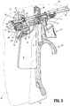
FIG. 5 is a rear, perspective view of the handle, trigger, and drive assemblies of the surgical instrument ofFIG. 1 with a movable handle of the handle assembly disposed in a partially-actuated position and a trigger of the trigger assembly disposed in an un-actuated position; -
FIG. 6 is a front, perspective view of the drive assembly, shaft, and end effector assembly of the surgical instrument ofFIG. 1 ; -
FIG. 7 is an enlarged, perspective view of the area of detail indicated as "7" inFIG. 6 ; -
FIG. 8 is another enlarged, perspective view of the proximal end of the drive assembly of the surgical instrument ofFIG. 1 ; -
FIG. 9 is a longitudinal, cross-sectional view taken along section line "9-9" ofFIG. 8 ; -
FIG. 10 is a rear, perspective, exploded view of the drive assembly, shaft, knife, and end effector assembly of the surgical instrument ofFIG. 1 ; -
FIG. 11 is an enlarged, perspective view of the area of detail indicated as "11" inFIG. 10 ; -
FIG. 12 is another enlarged, perspective view of the distal end of the knife blade of the surgical instrument ofFIG. 1 ; -
FIG. 12' is an enlarged, perspective view of the distal end of another knife blade configured for use with the surgical instrument ofFIG. 1 or any other suitable surgical instrument; -
FIG. 13 is a perspective view of the distal end of the surgical instrument ofFIG. 1 with the jaw members disposed in the spaced-apart position; -
FIG. 14 is another perspective view of the distal end of the surgical instrument ofFIG. 1 with the jaw members disposed in the spaced-apart position; -
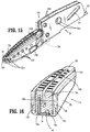
FIG. 15 is a side, perspective view of one of the jaw members of the surgical instrument ofFIG. 1 with a portion thereof removed; -
FIG. 16 is a transverse, cross-sectional view of the jaw member ofFIG. 15 ; -
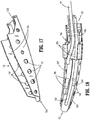
FIG. 17 is a perspective view of the electrically-conductive plate of one of the jaw members of the surgical instrument ofFIG. 1 ; -
FIG. 18 is a top view of the electrically-conductive plate of one of the jaw members of the surgical instrument ofFIG. 1 including an overmolded spacer disposed thereon; -
FIG. 19 is a perspective view of the electrically-conductive plate, jaw frame, and overmolded spacer of one of the jaw members of the surgical instrument ofFIG. 1 ; -
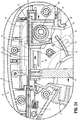
FIG. 20 is a longitudinal, cross-sectional view of the surgical instrument ofFIG. 1 with the surgical instrument disposed in an initial position; -
FIG. 21 is an enlarged, side, cross-sectional view of the area of detail indicated as "21" inFIG. 20 ; -
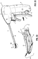
FIG. 22 is a perspective view of the surgical instrument ofFIG. 1 with the movable handle disposed in a compressed position and, accordingly, the jaw members disposed in the approximated position; -
FIG. 23 is an enlarged, perspective view of the area of detail indicated as "23" inFIG. 22 ; -
FIG. 24 is an enlarged, longitudinal, cross-sectional view of the internal components of the housing of the surgical instrument ofFIG. 1 , wherein the movable handle is disposed in the compressed position; -
FIG. 25 is a perspective view of the distal end of the drive, knife, and end effector assemblies of the surgical instrument ofFIG. 1 , with the jaw members disposed in the spaced-apart position; -
FIG. 26 is a perspective view of the distal end of the drive, knife, and end effector assemblies of the surgical instrument ofFIG. 1 , with the jaw members disposed in the approximated position; -
FIG. 27 is a perspective view of the proximal end of the surgical instrument ofFIG. 1 with the movable handle disposed in an activated position and a portion of the housing removed to illustrate the internal components thereof; -
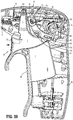
FIG. 28 is a perspective view of the proximal end of the surgical instrument ofFIG. 1 with the trigger disposed in an actuated position and a portion of the housing removed to illustrate the internal components thereof; -
FIG. 29 is a perspective view of the distal end of the drive and knife assemblies of the surgical instrument ofFIG. 1 with the knife assembly disposed in an extended position; and -
FIG. 30 is a perspective view of the distal end of the drive and knife assemblies as shown inFIG. 29 and further including the jaw members disposed in the approximated position. - Referring generally to
FIG. 1 , a surgical instrument provided in accordance with the present disclosure is shown generally identified byreference numeral 10.Instrument 10, as described below, is configured for grasping, treating, and/or dissecting tissue and may find particular applicability for use in performing tonsillectomy procedures and/or adenoidectomy procedures, although use ofinstrument 10 in various other surgical procedures is also contemplated and within the scope of the present disclosure. Additional features contemplated for use withinstrument 10 are detailed in commonly-ownedU.S. Patent Application Nos. 14/719,422 ,14/719,434 14/719,452 14/719,464 14/719,475 - With reference to
FIGS, 1-3 ,5 , and10 ,instrument 10 generally includes ahousing 20, ahandle assembly 30, atrigger assembly 70, ashaft 80, anend effector assembly 100, adrive assembly 140, aknife assembly 170, and anenergy activation assembly 190. As detailed below,shaft 80 extends distally fromhousing 20 and supportsend effector assembly 100 at distal end ofshaft 80,drive assembly 140 operably couples handleassembly 30 withend effector assembly 100 to enable selective manipulation ofjaw members end effector assembly 100,knife assembly 170 is operably coupled withtrigger assembly 70 to enable selective translation of a knife blade 174 (FIGS. 11 and 12 ) ofknife assembly 170 relative to endeffector assembly 100, andenergy activation assembly 190 enables energy to be selectively delivered to endeffector assembly 100. -
Instrument 10 also includes anelectrosurgical cable 200 including aproximal plug 210 that connectsinstrument 10 to a generator (not shown) or other suitable power source, althoughinstrument 10 may alternatively be configured as a battery-powered instrument.Electrosurgical cable 200 includes lead wires, e.g., lead wires 107 (FIG. 10 ), extending therethrough that have sufficient length to extend throughhousing 20 andshaft 80 in order to operably couple the generator,energy activation assembly 190, and endeffector assembly 100 with one another to enable the selective supply of energy to electrically-conductive plates 112, 122 ofjaw members end effector assembly 100, e.g., upon activation ofactivation switch 194 ofenergy activation assembly 190. - Referring to
FIGS. 1-3 ,housing 20 houses the internal working components ofinstrument 10 and is formed from first and second housing components configured to engage one another via a plurality of pin-aperture engagements spaced aroundhousing 20, although other suitable engagements, e.g., screws, snap-fit connections, adhesion, ultrasonic welding, etc., are also contemplated, as are different formations ofhousing 20.Housing 20 defines a pistol-style configuration having a longitudinally-extendingbarrel portion 22 and a fixedhandle portion 28 that extends frombarrel portion 22 in generally perpendicular orientation relative thereto. -
Barrel portion 22 ofhousing 20 defines a distal aperture configured to receive and engage the proximal end ofshaft 80 therein.Shaft 80 extends distally frombarrel portion 22 ofhousing 20 and defines a generally rectangular cross-sectional configuration oriented such that the larger width dimension thereof extends laterally and the smaller height dimension thereof extends vertically. This configuration ofshaft 80 relative to the orientation ofjaw members end effector assembly 100. As described in greater detail below,shaft 80 includes a pair of spaced-apart clevismembers 84 extending from the top and bottom walls, e.g., the larger width dimension walls, ofshaft 80 at the distal end ofshaft 80. Eachclevis member 84 defines anaperture 86 for receiving apivot pin 103 to operably supportend effector assembly 100 at the distal end ofshaft 80. -
Barrel portion 22 of housing further includes a pair of opposed pivot apertures 23 (only one of which is shown), alongitudinal track 24, a pair of opposed pivot bosses 25 (only one of which is shown), and ablock 26. Eachpivot aperture 23 is configured to receive an end ofpivot pin 48 to pivotably couplemovable handle 40 and trigger 72 tohousing 20. Alternatively, a separate pivot pin 48' received between separate pivot apertures 23' (only one of which is shown) may be provided fro couplingmovable handle 40 tohousing 20 such thatmovable handle 30 and trigger 72 are not coupled about thesave pivot pin 48 but, rather, are coupled about spaced-apart pivot pins 48', 48, respectively. Further still,movable handle 40 and trigger 72 may be pivotably coupled about the same pivot pin, pivot pin 48', at the location of pivot apertures 23' rather thanpivot apertures 23.Longitudinal track 24 is configured to guide translation ofdrive assembly 140 relative tohousing 20.Pivot bosses 25 extend inwardly intohousing 20 and are configured to pivotablycouple linkage 76 oftrigger assembly 70 tohousing 20.Lower leg 163 oftorsion spring 160 ofdrive assembly 140 is configured toabut block 26 under bias to biasmovable handle 40 towards the initial position, as detailed below. -
Energy activation assembly 190 includes adepressible button 192 that is mechanically coupled to aswitch 194 mounted within abay 29 defined within fixedhandle portion 28 ofhousing 20 and is engagable by abutton activation post 196 extending proximally from a proximal side ofmovable handle 40 upon movement ofmovable handle 40 to the activated position, as detailed below.Switch 194 is configured to electrically communicate withend effector assembly 100 and the generator (not shown) via suitable electrical wiring, e.g., leads 107 (FIG. 10 ), extending throughhousing 20,shaft 80, and/orelectrosurgical cable 200 to enable energy to be supplied from the generator (not shown) to endeffector assembly 100 upon activation ofswitch 194. - Continuing with reference to
FIGS. 1-3 , handleassembly 30 includes amovable handle 40 that is movable relative to fixedhandle portion 28 ofhousing 20 between an initial position, a compressed position, and an activated position, as explained in greater detail below, to impart movement ofjaw members end effector assembly 100 between a spaced-apart position and an approximated position for grasping tissue therebetween and for initiating the supply of energy to endeffector assembly 100 for treating grasped tissue.Movable handle 40 and trigger 72 oftrigger assembly 70 are ergonomically configured to facilitate manipulation and operation ofinstrument 10.Movable handle 40, more specifically, defines a graspingportion 42 having anarcuate segment 43 and an elongatedproximal leg 44 that extends fromarcuate segment 43 the length of fixedhandle portion 28 ofhousing 20.Arcuate segment 43 culminates in adistal tail 45 and defines a sufficient diameter so as to operably receive a user's finger betweendistal tail 45 andproximal leg 44.Arcuate segment 43 further defines aconvex surface 46.Trigger 72, more specifically, defines an abuttingsurface 73 that abutsconvex surface 46 ofarcuate segment 43 ofmovable handle 40 and is complementarily contoured such that, in the initial position ofmovable handle 40 and the un-actuated position oftrigger 72, pinch points betweentrigger 72 andmovable handle 40 are eliminated. Further, trigger 72 surrounds the exposed part offlange portion 47 ofmovable handle 40 to eliminate pinch points therebetween. -
Movable handle 40, as noted above, includes graspingportion 42, which extends fromhousing 20 adjacent fixedhandle portion 28, andflange portion 47, which extends upwardly intohousing 20.Flange portion 47 is pivotably coupled withinhousing 20 at the free end offlange portion 47 viapivot pin 48.Pivot pin 48 is engaged within and extends betweenpivot apertures 23 ofhousing 20 to permitmovable handle 40 to pivot aboutpivot pin 48 and relative tohousing 20 between the initial position (FIGS. 1 and2 ), the compressed position (FIG. 22 ), and the activated position (FIG. 27 ).Flange portion 47 ofmovable handle 40 further includes a cut-out 49 defined therein and anengagement bulge 51 protruding therefrom. Cut-out 49 is configured to slidably receivedrive plate 142 ofdrive assembly 140 andknife plate 172 ofknife assembly 170.Engagement bulge 51 is configured to operably engageflange portion 47 ofmovable handle 40 withslider assembly 150 ofdrive assembly 140, as detailed below. - Referring to
FIGS. 5-10 ,drive assembly 140 includesdrive plate 142 andslider assembly 150.Drive plate 142 extends distally fromhousing 20 and throughshaft 80 to operably engageend effector assembly 100 such that, as detailed below, translation ofdrive plate 142 throughshaft 80 and relative to endeffector assembly 100 pivotsjaw members end effector assembly 100 between the spaced-apart and approximated positions. -
Slider assembly 150 operablycouples engagement bulge 51 offlange portion 47 ofmovable handle 40 withdrive plate 142 such that pivoting ofmovable handle 40 between the initial position and the compressed position pivotsjaw members end effector assembly 100 between the spaced-apart and approximated positions, while ensuring application of an appropriate closure force or closure force within an appropriate closure force range to tissue grasped betweenjaw members -
Slider assembly 150 includes aproximal housing 152, adistal extension 156 extending distally fromproximal housing 152, amandrel 158 disposed at the distal end ofdistal extension 156, and atorsion spring 160 operably coupled toproximal housing 152.Proximal housing 152 includes apost 153 configured to receivebody 161 oftorsion spring 160 thereabout and open upper and lower portions configured to permit passage of the upper andlower legs torsion spring 160 therethrough.Lower leg 163 extends downwardly fromproximal housing 152 and is positioned to abut block 26 (which may be configured as a half-moon boss) ofhousing 20, thereby biasingslider assembly 150 distally and, thus,movable handle 40 towards the initial position.Torsion spring 160 remains tensioned in the initial position ofmovable handle 40 such that a pre-load ondrive assembly 140 is maintained.Proximal housing 152 further includes anabutment rib 154 disposed on an upper surface thereof, and alongitudinal flange 155 slidably received withinlongitudinal track 24 ofhousing 20. - Continuing with reference to
FIGS. 5-10 ,mandrel 158 is disposed at the distal end ofdistal extension 156 and defines achannel 159 configured to receiveengagement bulge 51 offlange portion 47 ofmovable handle 40. As a result of this configuration, upon pivoting ofmovable handle 40 between the initial, compressed, and activated positions,engagement bulge 51 is urged into contact with one of the walls ofmandrel 156 to thereby translateslider assembly 150 withinhousing 20. -
Drive plate 142 includes aflange 143 and aslot 144 towards the proximal end thereof and acam pin aperture 147 and amouth 149 towards the distal end thereof.Slot 144 is configured to receiveupper leg 162 oftorsion spring 160 therethrough such that translation ofupper leg 162 oftorsion spring 160 relative tohousing 20 effects translation ofdrive plate 142 relative tohousing 20.Flange 143 is slidably disposed on an upper surface ofproximal housing 152 and defines aproximal edge 145 configured toabut abutment rib 154 ofproximal housing 152 in a proximal-most position ofdrive plate 142 relative toslider assembly 150 to inhibit further proximal movement ofdrive plate 142 relative toslider assembly 150. -
Drive plate 142 extends distally fromhousing 20 and throughshaft 80 to operably engageend effector assembly 100.Drive plate 142 is oriented similarly toshaft 80, such that the width ofdrive plate 142 extends along the width dimension ofshaft 80.Drive plate 142 further defines atrack edge 146 extending along a portion of each longitudinal side thereof. Track edges 146 are configured to slidably receiveknife plate 172. Aknife guide 148 is pinned to driveplate 142 towards the distal end thereof to define a channel configured to slidably receive and guide translation ofknife blade 174.Knife guide 148 also provides further stability tocam pin 105. Cam-pin aperture 147 is configured to receivecam pin 105 ofend effector assembly 100, whilemouth 149 is configured to receivepivot pin 103 ofend effector assembly 100. - Referring to
FIGS. 2-12 ,trigger assembly 70, as mentioned above, is operably coupled toknife assembly 170 to enable selective translation ofknife blade 174 ofknife assembly 170 relative to endeffector assembly 100.Trigger assembly 70 includestrigger 72 and alinkage 76.Trigger 72, as detailed above, includes an abuttingsurface 73 defined on a graspingportion 74 thereof.Trigger 72 further includes apivot extension 75a extending upwardly from graspingportion 74 and aproximal extension 75b extending proximally from graspingportion 74.Pivot extension 75a oftrigger 72 is pivotably coupled tohousing 20 viapivot pin 48.Proximal extension 75b oftrigger 72 includes apost 75c that is received within lowerend cam slot 77c oflinkage 76 to operably couple trigger 72 tolinkage 76. A biasingmember 71 is coupled betweenhousing 20 and trigger 72 tobias trigger 72 distally towards an un-actuated position (FIG. 2 ). -
Linkage 76 serves to operably couple trigger 72 withknife assembly 170 such that pivoting oftrigger 72 from the un-actuated position to the actuated position advances knife blade 174 (FIGS. 10-12 ) betweenjaw members end effector assembly 100 to cut tissue grasped therebetween.Linkage 76 includes an apex 77a pointing in a distal direction and upper and lowerend cam slots Apex 77a includes apeg 77d that is configured for receipt withinpivot boss 25 ofhousing 20 to pivotablycouple linkage 76 relative tohousing 20 aboutapex 77a. Acoupling tube 78 engaged withknife plate 172 ofknife assembly 170 is configured for receipt within upperend cam slot 77b tooperably couple linkage 76 toknife plate 172. More specifically,coupling tube 78 is configured to receivelegs 173, which extend transversely from the proximal end ofknife plate 172, in snap-fit engagement therein (seeFIG. 9 ). As noted above, post 75c ofproximal extension 75b oftrigger 72 is configured for receipt within lowerend cam slot 77c oflinkage 76. - As a result of the above-detailed configuration, Pivoting of
trigger 72 between the un-actuated and actuated positions urgeslinkage 76 to pivot relative tohousing 20 such thatcoupling tube 78 is urged to translate longitudinally within and relative tohousing 20. Aslegs 173 ofknife plate 172 are engaged withcoupling tube 78, such longitudinal translation ofcoupling tube 78 is imparted toknife plate 172 for translating knife blade 174 (FIGS. 10-12 ) from a retracted position to an extended position relative tojaw members end effector assembly 100. -
Linkage 76 oftrigger assembly 70 further includes alockout peg 79 extending transversely fromlinkage 76 and positioned betweenapex 77a and lowerend cam slot 77c. In the initial position ofmovable handle 40,proximal housing 152 ofslider assembly 150 is disposed in a more distal position so as to interfere with the movement path of lockout peg 79 (seeFIG. 21 ), thus inhibiting actuation oftrigger 72 whenmovable handle 40 is disposed in its initial position. Upon movement ofmovable handle 40 sufficiently towards the compressed position,proximal housing 152 ofslider assembly 150 is moved proximally out of the movement path of lockout peg 79 (seeFIG. 24 ), permitting rotation oflinkage 76 and, thus, actuation oftrigger 72. - With reference to
FIGS. 8-12 ,knife assembly 170, as noted above, includes aknife plate 172 defininglegs 173 extending transversely therefrom towards the proximal end thereof.Knife plate 172 extends distally throughhousing 20 andshaft 80 atopdrive plate 142 and is slidably engaged therewith via receipt of each side ofknife plate 172 within track edges 146 ofdrive plate 142.Knife assembly 170 further includesknife blade 174 integrally formed with or otherwise engaged toknife plate 172 and extending distally therefrom.Knife blade 174 is slidably disposed within the channel defined betweendrive plate 142 andknife guide 148 and defines a serrated distal cutting edge 175 (seeFIGS. 11 and 12 ) to facilitate cutting tissue grasped betweenjaw members end effector assembly 100.Knife blade 174 further defines anelongated opening 176 extending longitudinally therethrough.Elongated opening 176permits knife blade 174 to be slidably disposed aboutpivot pin 103 andcam pin 105. More specifically,elongated opening 176 defines afirst portion 177a, asecond portion 177b, and athird portion 177c (FIG. 10 ).First portion 177a has a first width configured to slidably receivepivot pin 103 andcam pin 105.Second portion 177b extends distally fromfirst portion 177a, has a second width, and is configured to facilitate compliance ofknife blade 174 as it is translated through the curved end effector assembly 100 (FIG. 13 ).Third portion 177c (FIG. 10 ) extends proximally fromfirst portion 177a and has a third width (equal to or different from the second width) configured to slidably receivecam pin 105 but sufficiently small to inhibit receipt of the larger-diameter pivot pin 103 therein. - Turning to
FIG. 12' , another knife blade 174' configured for use withinstrument 10 is provided. To the extent consistent, and unless contradicted hereinbelow, knife blade 174' may include similar features, functions, and connections to the other components ofinstrument 10 as those detailed herein with respect to knife blade 174 (FIGS. 11 and 12 ). Knife blade 174' defines a heighteneddistal portion 174a' and a relativelyshorter body portion 174b'. The heighteddistal portion 174a' of knife blade 174' inhibits tissue from being positioned above or below knife blade 174' as knife blade 174' is translating through end effector assembly 100 (FIG. 14 ), while theshorter body portion 174b' of knife blade 174' maintains a low profile configuration within shaft 80 (FIG. 14 ). Knife blade 174' further defines an elongated opening 177' therethrough that, although shown as having a generally constant width, may alternatively be configured similar toelongated opening 176 of knife blade 174 (FIGS. 11 and 12 ). - The distal cutting edge 175' of knife blade 174' defines a dual rake configuration, wherein the edge portions of distal cutting edge 175' extend distally and angle inwardly towards one another, ultimately culminating in a point that is generally centered about a longitudinal axis of knife blade 174' and positioned distally of heightened
distal portion 174a' of knife blade 174'. This configuration of distal cutting edge 175' has been found to: reduce the force required to advance knife blade 174' through tissue due to its aerodynamic configuration; enable cutting further towards the distal tip of end effector assembly 100 (FIG. 14 ) by virtue of the inwardly and distally extending cutting edge potions of distal cutting edge 175'; and enable a reduction in overall jaw height for either or both of thejaw members - With reference to
FIGS. 10 and13-19 , as mentioned above,end effector assembly 100 is operably supported at the distal end ofshaft 80 and includes opposingjaw members shaft 80 between a spaced-apart position and an approximated position for grasping tissue therebetween.Jaw members jaw member 110 andjaw member 120 may not be described and/or illustrated with respect to each ofjaw members - Each
jaw member conductive plate 132, ajaw frame 134, aspacer 136, and anouter housing 138, each of which is detailed below.Jaw members jaw members shaft 80, e.g., towards the upper, larger width dimension wall ofshaft 80. This configuration facilitates use ofinstrument 10 in tonsillectomy and adenoidectomy procedures as well as other surgical procedures and allows for increased visualization of the surgical site in these and other procedures. - The electrically-
conductive plate 132 of eachjaw member surface 132a, anelongated knife slot 132b extending through the respective tissue-contactingsurface 132a, a pair oflegs 132c extending downwardly from each side of the respective tissue-contactingsurface 132a, and adistal edge 132d disposed at the distal end of the respective tissue-contactingsurface 132a. - The tissue-contacting
surface 132a ofjaw member 110 and/orjaw member 120 may include a plurality ofstop members 132e disposed thereon.Stop members 132e may be constructed of a heat-resistant ceramic, a non-conductive plastic, an electrically conductive material isolated from the respective tissue-contactingsurface 132a, or any other suitable material, and/or may be deposited, molded, inserted through apertures, or otherwise formed on the tissue-contactingsurface 132a ofjaw member 110 and/orjaw member 120.Legs 132c of electrically-conductive plates 132 each define a plurality ofapertures 132f therethrough. - Jaw frames 134 of
jaw members proximal flanges 134a and adistal jaw support 134b extending distally from theproximal flanges 134a.Proximal flanges 134a ofjaw member 110 are spaced-apart further thanproximal flanges 134a ofjaw member 120 so as to allowproximal flanges 134a ofjaw member 120 to be positioned betweenproximal flanges 134a ofjaw member 110 during assembly. Further, theproximal flanges 134a of each pair define alignedpivot apertures 134c and alignedcam slots 134d.Pivot pin 103 ofend effector assembly 100 is configured for vertical insertion throughapertures 86 of clevismembers 84 ofshaft 80 and pivot apertures 13c to pivotablycouple jaw members shaft 80 and one another.Pivot pin 103 is further configured to at least partially entermouth 149 ofdrive plate 142 to permitdrive plate 142 to slide further distally relative to endeffector assembly 100 to a position whereinmouth 149 ofdrive plate 142 at least partially surroundspivot pin 103. - Continuing with reference to
FIGS. 10 and13-19 , thecam slots 134d ofproximal flanges 134a ofjaw member 110 are oppositely angled relative to thecam slots 134d ofproximal flanges 134a ofjaw member 120.Cam pin 105 ofend effector assembly 100 is configured for insertion through eachcam slot 134d as well as cam-pin aperture 147 ofdrive plate 142 to operable couple driveplate 142 withjaw members drive plate 142 relative tojaw members jaw members pivot pin 103 and relative to one another andshaft 80 between the spaced-apart and approximated positions. - Distal jaw supports 134b of jaw frames 134 of
jaw members conductive plates 132,spacers 136, andouter housings 138 ofjaw members jaw members -
Spacers 136 ofjaw members Spacers 136 are positioned to electrically-isolate electrically-conductive plates 132 from one another and from jaw frames 134.Spacers 136 each define abody 136a, a pair ofwings 136b surrounding body 136a, and a pair ofsupport arms 136c extending distally from thecorresponding body 136a. Thebodies 136a ofspacers 136 definetunnels 136e for passage oflead wires 107 therethrough to electrically couple electrically-conductive plates 132 to switch 194 of energy activation assembly 190 (FIGS. 1 and2 ) and the generator (not shown).Wings 136b capture thelegs 132c of electrically-conductive plates 132. -
Support arms 136c ofspacers 136b extend along thelegs 132c of electrically-conductive plate 132 to provide structural support thereto, and may define equal or different lengths. For example, due to the curved configuration ofjaw members support arm 136c adjacent thereto may be longer than thesupport arm 136c adjacent the outer or convex side. However, other configurations are also contemplated.Support arms 136c further includeprotrusions 136d that extend therefrom through some but not all of theapertures 132f defined along the length oflegs 132c of electrically-conductive plates 132 to securesupport arms 136c thereto and reinforce the structural stability thereof. The above-detailed configuration ofsupport arms 136c inhibitslegs 132c of electrically-conductive plates 132 from bending, buckling, and/or becoming wave-shaped under the forces applied thereto during overmolding, assembly, and/or use. -
Outer housings 138 are formed aboutjaw members outer housing 138 partially enclosesrespective jaw members apertures 132f defined throughlegs 132c of electrically-conductive plates 132 that are not occupied byprotrusions 136d ofarms 136c ofspacers 136 are filled via portions ofouter housing 138 during the second overmold process to ensure that electrically-conductive plates 132 are secured in position.Outer housings 138 also definewindows 139 that align with and communicate with theknife slots 132b of electrically-conductive plates 132 so as to define an opening through the distal portions ofjaw members surfaces 132a of electrically-conductive plates 132 to the outer surfaces ofouter housings 138. - With
outer housings 138 formed aboutjaw members distal edges 132d of electrically-conductive plates 132 overlap the distal ends ofouter housings 138 such thatdistal edges 132d can be utilized to pinch tissue therebetween. Further,outer housings 138 each define cut-outs on the outer surfaces thereof towards the distal ends thereof that formshelves 109 on the outer surfaces ofjaw members - Turning now to
FIGS. 20-30 , the use and operation ofinstrument 10 is described. Initially, as illustrated inFIGS. 20 ,21 , and25 ,movable handle 40 is biased towards the initial position by the abutment oflower leg 163 oftorsion spring 160 withblock 26 ofhousing 20. Withmovable handle 40 in the initial position,slider assembly 150 is likewise disposed in a distal-most position. Withslider assembly 150 disposed in its distal-most position,upper leg 162 oftorsion spring 160 retainsdrive plate 142 in a distal-most position with theproximal edge 145 ofdrive plate 142 disposed in abutment withabutment rib 154 ofproximal housing 152 ofslider assembly 150. In the distal-most position ofdrive plate 142,drive plate 142 andknife guide 148 maintaincam pin 105 at the distal ends of oppositely-angledcam slots 134d ofproximal flanges 134a ofjaw members jaw members FIG. 25 ). - At this point, with continued reference to
FIGS. 20 ,21 , and25 ,trigger 72 is disposed in the un-actuated position, whereintrigger 72 is in a distal-most position under the bias of biasingmember 71 such that upperend cam slot 77b oflinkage 76 is disposed in a proximal-most position while lowerend cam slot 77c oflinkage 76 is disposed in a distal-most position. Thus,knife plate 172 is disposed in a proximal-most position, corresponding to a retracted position ofknife blade 174, whereinknife blade 174 is disposed betweenproximal flanges 134a of jaw frames 134 ofjaw members movable handle 40 disposed in its initial position,proximal housing 152 ofslider assembly 150 is disposed in the movement path of lockout peg 79 oflinkage 76, inhibiting rotation oflinkage 76 and, thus, inhibiting movement oftrigger 72 from the un-actuated position to the actuated position. As such,knife blade 174 is inhibited from being deployed whenjaw members - With additional reference to
FIGS. 22-24 , and26 , in order to movejaw members movable handle 40 is pulled proximally towards fixedhandle portion 28 ofhousing 20 from the initial position to the compressed position (FIGS. 22 and24 ). Upon movement ofmovable handle 40 to the compressed position,movable handle 40urges slider assembly 150 proximally throughhousing 20.Torsion spring 160, in an initial, less-tensioned state, is translated proximally together withslider assembly 150 such thatupper leg 162 oftorsion spring 160 pullsdrive plate 142 proximally in connection with the proximal translation ofslider assembly 150. In other words, at this point,slider assembly 150 and driveplate 142 move in concert with one another. Asdrive plate 142 is pulled proximally,cam pin 105 is pulled proximally throughcam slots 134d ofproximal flanges 134a ofjaw members jaw members FIGS. 23 and26 ) to grasp tissue therebetween. - Referring also to
FIG. 27 , in order to apply energy to tissue grasped betweenjaw members movable handle 40 is compressed further towards fixedhandle portion 28 ofhousing 20 to an activation position, wherein an appropriate closure force or closure force within an appropriate range, is achieved and energy activation is initiated. Asmovable handle 40 is moved further proximally relative tohousing 20 beyond the compressed position, an appropriate closure force or closure force within an appropriate range is imparted to tissue grasped betweenjaw members movable handle 40. This is because, upon movement ofmovable handle 40 from the compressed position towards the activation position,proximal housing 152 ofslider assembly 150 is translated proximally whiledrive plate 142 is maintained in position. In other words, upon movement ofmovable handle 40 from the compressed position to the activated position,proximal housing 152 and driveplate 142 no longer move in concert with one another but are decoupled to permit relative motion therebetween. - The decoupling of
proximal housing 152 ofslider assembly 150 and driveplate 142 to permit relative motion therebetween is provided viatorsion spring 160. More specifically, upon proximal movement ofmovable handle 40, a first force is imparted frommovable handle 40, throughproximal housing 152 ofslider assembly 150,body 161 oftorsion spring 160, andupper leg 162 oftorsion spring 160, to driveplate 142 to urgedrive plate 142 in a proximal direction, while a second, opposite force acts ondrive plate 142 and, thus,upper leg 162 oftorsion spring 160 in a distal direction to control the amount of compression of tissue betweenjaw members torsion spring 160, proximal movement ofproximal housing 152 no longer results in proximal movement ofdrive plate 142 but, rather, results in further tensioning oftorsion spring 160, whereintorsion spring 160 is wound-up, absorbing the force imparted thereto from movement ofmovable handle 40. Thus, once this point has been reached, further proximal translation ofproximal housing 152 ofslider assembly 150 urgesbody 161 oftorsion spring 160 proximally whileupper leg 162 oftorsion spring 160 remains in position as a result of the wind-up tensioning oftorsion spring 160. Withupper leg 162 oftorsion spring 160 retained in position,drive plate 142 is likewise retained in position despite the proximal translation ofmovable handle 40. As such, an upper threshold of pressure applied to tissue grasped betweenjaw members - Referring to
FIG. 27 , upon achieving the activation position ofmovable handle 40, button activation post 196 (FIG. 1 ) ofmovable handle 40 contactsdepressible button 192 sufficiently so as to depressdepressible button 192 into fixedhandle portion 28 ofhousing 20 to activateswitch 194.Switch 194, as noted above, is disposed in electrical communication with the generator (not shown) and electrically-conductive plates 132 ofjaw members 110, 120 (FIG. 14 ), such that activation ofswitch 194 initiates the supply of energy to electrically-conductive plates 132 (FIG. 14 ) to treat, e.g., coagulate, cauterize, and/or seal, tissue grasped therebetween. - Referring to
FIGS. 28-30 , once tissue has been treated or where it is only desired to cut tissue,knife blade 174 may be advanced betweenjaw members knife blade 174 from the retracted position to the extended position, trigger 72 is pulled proximally against the bias of biasingmember 71 from the un-actuated position to the actuated position. Astrigger 72 is pulled proximally,linkage 76 is urged to pivot counterclockwise (from the orientation illustrated inFIG. 28 ) such thatupper end slot 77b oflinkage 76 is moved distally. Distal movement ofupper end slot 77b urgestube 78 to translate distally and, in turn, urgesknife plate 172 to translate distally. This movement is permitted as, withmovable handle 40 in or near the compressed or actuated position,proximal housing 152 is displaced relative to the movement path oflockout peg 79. - As detailed above, movement of
trigger 72 from the un-actuated position to the actuated position urgesknife plate 172 distally. More specifically,knife plate 172 is urged distally such thatknife blade 174 is advanced distally from the retracted position to the extended position. Asknife blade 174 is advanced distally,knife blade 174 extends throughknife slots 132b defined within electrically-conductive plates 132 ofjaw members jaw members - Upon release, trigger 72 and
knife plate 172 are returned proximally under the bias of biasingmember 71 such thatknife blade 174 is returned to the retracted position. Thereafter,movable handle 40 may be released, allowingmovable handle 40 to return to the initial position under the bias oflower leg 163 oftorsion spring 160 abuttingblock 26 ofhousing 20, thereby returningjaw members - Referring generally to
FIGS. 1-10 , the assembly ofsurgical instrument 10 is detailed. Unless necessitated by the positioning of the components, e.g., wherein a second component obstructs a first components, the assembly ofsurgical instrument 10 need not be performed in the order detailed below. Further, it is contemplated that certain assemblies and/or components, e.g., each of thejaw members 110, 120 (the assembly of which is detailed above), be pre-assembled prior to engagement with the other components ofsurgical instrument 10. - The previously-assembled
jaw members proximal flanges 134a ofjaw member 110 receive theproximal flanges 134a ofjaw member 120 therebetween with thepivot apertures 134c thereof aligned with one another.Leads 107, which extend proximally fromjaw members shaft 80. - Knife plate 172 (including
knife blade 174 at the distal end thereof) is slidably coupled to driveplate 142 via insertion ofknife blade 174 betweenplate 142 andknife guide 148 with the longitudinal edges ofknife plate 172 are slidably received within track edges 146 ofdrive plate 142. Prior to or after coupling ofknife plate 172 and driveplate 142,coupling tube 78 is snap-fit aboutlegs 173 ofknife plate 172. - With
knife plate 172 and driveplate 142 coupled to one another, the pair is inserted through the proximal end ofshaft 80 untilcam pin aperture 147 ofdrive plate 142 andelongated opening 176 ofknife blade 174 are aligned withcam slots 134d ofjaw members cam pin 105 may be inserted therethrough to operably couple driveplate 142 withjaw members - With
cam pin 105 operablycoupling jaw members drive plate 142,proximal flanges 134a ofjaw members members 84 ofshaft 80 such thatpivot pin apertures 86 ofshaft 80 are aligned withpivot apertures 134c ofjaw members apertures pivot pin 103 may be inserted therethrough to pivotablycouple jaw members shaft 80 and one another. Achieving the above insertion ofcam pin 105 and/orpivot pin 103 may be facilitated using appropriate fixturing (not shown) and/or a lead pin (not shown). To securepivot pin 103 in position,pivot pin 103 may be laser welded to the exterior ofshaft 80 about the perimeter ofpivot pin 103 andapertures 86 ofshaft 80. Testing may be performed after welding to ensure proper pivoting ofjaw members drive plate 142 and to ensure proper advancement and retraction ofknife blade 174 relative tojaw members - In order to assemble and install
drive assembly 140,torsion spring 160 is positioned withinproximal housing 152 ofslider assembly 150 such that post 153 ofproximal housing 152 receivesbody 161 oftorsion spring 160 with upper andlower legs torsion spring 160 extending fromproximal housing 152.Proximal housing 152 and/or the proximal end ofdrive plate 142 are then manipulated such that the proximal end ofdrive plate 142 is slidably supported atopproximal housing 152 withupper leg 162 oftorsion spring 160 extending throughslot 144 defined withindrive plate 142. - The assembly thus far (end
effector assembly 100,shaft 80,drive plate 142,slider assembly 150, and knife assembly 170) is positioned within one of the first or second housing components ofhousing 20 such thatshaft 80 is fixed in position relative thereto,proximal housing 152 is slidably received withinlongitudinal track 24 ofhousing 20, andlower leg 163 oftorsion spring 160 abuts a distally-facing surface ofblock 26 ofhousing 20.Leads 107 are routed aroundhousing 20 so as not to interfere with the internal operating components thereof, are connected toactivation assembly 190, and are connected toelectrosurgical cable 200, which extends fromhousing 20. - Next,
pivot pin 48 formovable handle 40 is inserted into thepivot aperture 23 of the housing component ofhousing 20 and, thereafter,movable handle 40 is positioned to pivotably couple tohousing 20 viapivot pin 48 and such thatengagement bulge 51 is operably coupled withmandrel 158 ofslider assembly 150, withdrive plate 142 andknife plate 172 received within cut-out 49 ofmovable handle 40.Trigger 72 is then positioned atop and at least partially aboutmovable handle 40, withpivot pin 48pivotably coupling trigger 72 tohousing 20. Biasingspring 71 is also connected for biasingtrigger 72 towards the un-actuated position.Linkage 76 is then disposed atoptrigger 72 such thatpeg 77d is pivotably engaged withpivot boss 25 of the housing component ofhousing 20,coupling tube 78 is received within upperend cam slot 77b oflinkage 76, and lowerend cam slot 77c oflinkage 76 receivespost 75c oftrigger 72. Thus, trigger andlinkage 76 are operably coupled tohousing 20,knife plate 172, and one another. - Once the internal components within
housing 20 are assembled and in place, as detailed above, the outer housing components ofhousing 20 are positioned such that the outer housing components cooperate to enclose the internal components. The outer housing components may be engaged with one another in any suitable fashion, e.g., screws, snap-fit engagements, ultrasonic welding, adhesion, etc. - Finally, testing is performed to ensure that
surgical instrument 10 is working properly. Such testing may include jaw force testing; testing using a gauge pin (not shown) to test the maximum jaw aperture betweenjaw members knife blade 174 using cut test media (not shown); testing of the gap distance between the tissue-contactingsurfaces 132a ofjaw members 110, 120 (as set by the one ormore stop members 132e) in the approximated position thereof at various positions along the lengths ofjaw members - The various embodiments disclosed herein may also be configured to work with robotic surgical systems and what is commonly referred to as "Telesurgery." Such systems employ various robotic elements to assist the surgeon and allow remote operation (or partial remote operation) of surgical instrumentation. Various robotic arms, gears, cams, pulleys, electric and mechanical motors, etc. may be employed for this purpose and may be designed with a robotic surgical system to assist the surgeon during the course of an operation or treatment. Such robotic systems may include remotely steerable systems, automatically flexible surgical systems, remotely flexible surgical systems, remotely articulating surgical systems, wireless surgical systems, modular or selectively configurable remotely operated surgical systems, etc.
- The robotic surgical systems may be employed with one or more consoles that are next to the operating theater or located in a remote location. In this instance, one team of surgeons or nurses may prep the patient for surgery and configure the robotic surgical system with one or more of the instruments disclosed herein while another surgeon (or group of surgeons) remotely control the instruments via the robotic surgical system. As can be appreciated, a highly skilled surgeon may perform multiple operations in multiple locations without leaving his/her remote console which can be both economically advantageous and a benefit to the patient or a series of patients.
- The robotic arms of the surgical system are typically coupled to a pair of master handles by a controller. The handles can be moved by the surgeon to produce a corresponding movement of the working ends of any type of surgical instrument (e.g., end effectors, graspers, knifes, scissors, etc.) which may complement the use of one or more of the embodiments described herein. The movement of the master handles may be scaled so that the working ends have a corresponding movement that is different, smaller or larger, than the movement performed by the operating hands of the surgeon. The scale factor or gearing ratio may be adjustable so that the operator can control the resolution of the working ends of the surgical instrument(s).
- The master handles may include various sensors to provide feedback to the surgeon relating to various tissue parameters or conditions, e.g., tissue resistance due to manipulation, cutting or otherwise treating, pressure by the instrument onto the tissue, tissue temperature, tissue impedance, etc. As can be appreciated, such sensors provide the surgeon with enhanced tactile feedback simulating actual operating conditions. The master handles may also include a variety of different actuators for delicate tissue manipulation or treatment further enhancing the surgeon's ability to mimic actual operating conditions.
- From the foregoing and with reference to the various figure drawings, those skilled in the art will appreciate that certain modifications can also be made to the present disclosure without departing from the scope of the same. While several embodiments of the disclosure have been shown in the drawings, it is not intended that the disclosure be limited thereto, as it is intended that the disclosure be as broad in scope as the art will allow and that the specification be read likewise. Therefore, the above description should not be construed as limiting, but merely as exemplifications of particular embodiments. Those skilled in the art will envision other modifications within the scope and spirit of the claims appended hereto.
- The invention may be described by reference to the following numbered paragraphs:-
- 1. A surgical instrument, comprising:
- a housing;
- a shaft extending distally from the housing;
- an end effector assembly disposed at a distal end of the shaft;
- a knife slidably disposed within the shaft;
- a movable handle operably coupled to the housing and movable relative thereto between an initial position and a compressed position;
- a trigger operably coupled to the housing and movable relative thereto between an un-actuated position and an actuated position;
- a drive assembly operably coupled between the movable handle and the end effector assembly such that movement of the movable handle from the initial position to the compressed position moves the drive assembly to thereby manipulate the end effector assembly, the drive assembly including a drive housing; and
- a linkage operably coupled between the trigger and the knife such that movement of the trigger from the un-actuated position to the actuated position moves the linkage to thereby deploy the knife relative to the end effector assembly, the linkage defining a path of movement;
- wherein, in the initial position of the movable handle, a portion of the drive housing intersects the path of movement to inhibit movement of the linkage to deploy the knife, thereby inhibiting movement of the trigger from the un-actuated position to the actuated position.
- 2. The surgical instrument according to
paragraph 1, wherein movement of the trigger from the un-actuated position to the actuated position urges the linkage to rotate to thereby deploy the knife. - 3. The surgical instrument according to
paragraph 1, wherein the linkage includes a protruding lockout peg, and wherein, in the initial position of the movable handle, the drive housing intersects a path of movement of the lockout peg. - 4. The surgical instrument according to
paragraph 1, wherein the drive housing is translated proximally relative to the linkage upon movement of the movable handle from the initial position to the compressed position such that the drive housing is proximally displayed relative to the path of movement. - 5. The surgical instrument according to
paragraph 1, wherein the movable handle and the trigger are pivotably coupled to the housing. - 6. The surgical instrument according to paragraph 5, wherein the movable handle and the trigger are pivotably coupled to the housing about a common pivot.
- 7. The surgical instrument according to
paragraph 1, wherein the end effector assembly includes first and second jaw members, at least one of the first or second jaw members movable relative to the other from a spaced-apart position to an approximated position upon movement of the movable handle from the initial position to the compressed position. - 8. The surgical instrument according to paragraph 7, wherein the drive housing at least partially houses a spring configured to limit a pressure applied by the first and second jaw members.
- 9. The surgical instrument according to paragraph 8, wherein the spring is a torsion spring.
- 10. The surgical instrument according to
paragraph 1, wherein the trigger at least partially surrounds the movable handle. - 11. The surgical instrument according to
paragraph 10, wherein the trigger and the movable handle define complementarily-contoured abutting surfaces. - 12. A jaw member configured for use with a surgical instrument, comprising:
- an electrically-conductive plate defining a planar tissue-contacting surface and a pair of legs extending from the planar tissue-contacting surface, the legs defining outwardly-facing surfaces and inwardly-facing surfaces;
- a spacer including a body positioned towards a proximal portion of the electrically-conductive plate, and a pair of arms extending distally from the body adjacent the inwardly-facing surfaces to provide structural support to the electrically-conductive plate;
- a jaw frame supporting the spacer and the electrically-conductive plate; and
- an outer housing disposed about at least a portion of the outwardly-facing surfaces of the legs of the electrically-conductive plate, the spacer, and the jaw frame.
- 13. The jaw member according to paragraph 12, wherein the spacer further includes a pair of wings extending outwardly from the body, the wings configured to receive free ends of the legs of the electrically-conductive plate to engage the spacer with the electrically-conductive plate.
- 14. The jaw member according to paragraph 12, wherein the legs of the electrically-conductive plate each define a plurality of apertures therethrough.
- 15. The jaw member according to paragraph 14, wherein the arms of the spacer define protrusions extending outwardly therefrom, each protrusion extending at least partially through one of the plurality of apertures.
- 16. The jaw member according to paragraph 15, wherein a portion of the outer housing extends at least partially through one of the plurality of apertures of each of the legs of the electrically-conductive plate.
- 17. The jaw member according to paragraph 12, wherein the spacer further defines a tunnel configured to receive a wire for connecting the electrically-conductive plate to a source of energy.
- 18. The jaw member according to paragraph 12, wherein the jaw frame includes a distal support portion that extends from about 50% to about 75% of the length of the electrically-conductive plate.
- 19. The jaw member according to paragraph 18, wherein the jaw frame includes a proximal flange portion extending proximally from the distal support portion, the proximal flange portion defining at least one pivot aperture and at least one cam slot.
- 20. The jaw member according to paragraph 12, wherein the legs extend perpendicularly from the planar tissue-contacting surface.
Claims (15)
- A surgical instrument, comprising:a housing;a shaft extending distally from the housing;an end effector assembly disposed at a distal end of the shaft;a knife slidably disposed within the shaft;a movable handle operably coupled to the housing and movable relative thereto between an initial position and a compressed position;a trigger operably coupled to the housing and movable relative thereto between an un-actuated position and an actuated position;a drive assembly operably coupled between the movable handle and the end effector assembly such that movement of the movable handle from the initial position to the compressed position moves the drive assembly to thereby manipulate the end effector assembly, the drive assembly including a drive housing; anda linkage operably coupled between the trigger and the knife such that movement of the trigger from the un-actuated position to the actuated position moves the linkage to thereby deploy the knife relative to the end effector assembly, the linkage defining a path of movement;wherein, in the initial position of the movable handle, a portion of the drive housing intersects the path of movement to inhibit movement of the linkage to deploy the knife, thereby inhibiting movement of the trigger from the un-actuated position to the actuated position.
- The surgical instrument according to claim 1, wherein movement of the trigger from the un-actuated position to the actuated position urges the linkage to rotate to thereby deploy the knife.
- The surgical instrument according to claim 1 or 2, wherein the linkage includes a protruding lockout peg, and wherein, in the initial position of the movable handle, the drive housing intersects a path of movement of the lockout peg.
- The surgical instrument according to claim 1, 2 or 3, wherein the drive housing is translated proximally relative to the linkage upon movement of the movable handle from the initial position to the compressed position such that the drive housing is proximally displayed relative to the path of movement.
- The surgical instrument according to claim 1, wherein the movable handle and the trigger are pivotably coupled to the housing, preferably
wherein the movable handle and the trigger are pivotably coupled to the housing about a common pivot. - The surgical instrument according to any preceding claim, wherein the end effector assembly includes first and second jaw members, at least one of the first or second jaw members movable relative to the other from a spaced-apart position to an approximated position upon movement of the movable handle from the initial position to the compressed position.
- The surgical instrument according to claim 6, wherein the drive housing at least partially houses a spring configured to limit a pressure applied by the first and second jaw members, preferably
wherein the spring is a torsion spring. - The surgical instrument according to any preceding claim, wherein the trigger at least partially surrounds the movable handle, preferably wherein the trigger and the movable handle define complementarily-contoured abutting surfaces.
- A jaw member configured for use with a surgical instrument, comprising:an electrically-conductive plate defining a planar tissue-contacting surface and a pair of legs extending from the planar tissue-contacting surface, the legs defining outwardly-facing surfaces and inwardly-facing surfaces;a spacer including a body positioned towards a proximal portion of the electrically-conductive plate, and a pair of arms extending distally from the body adjacent the inwardly-facing surfaces to provide structural support to the electrically-conductive plate;a jaw frame supporting the spacer and the electrically-conductive plate; andan outer housing disposed about at least a portion of the outwardly-facing surfaces of the legs of the electrically-conductive plate, the spacer, and the jaw frame.
- The jaw member according to claim 9, wherein the spacer further includes a pair of wings extending outwardly from the body, the wings configured to receive free ends of the legs of the electrically-conductive plate to engage the spacer with the electrically-conductive plate.
- The jaw member according to claim 9 or 10, wherein the legs of the electrically-conductive plate each define a plurality of apertures therethrough, preferably
wherein the arms of the spacer define protrusions extending outwardly therefrom, each protrusion extending at least partially through one of the plurality of apertures. - The jaw member according to claim 11, wherein a portion of the outer housing extends at least partially through one of the plurality of apertures of each of the legs of the electrically-conductive plate.
- The jaw member according to any preceding claim, wherein the spacer further defines a tunnel configured to receive a wire for connecting the electrically-conductive plate to a source of energy.
- The jaw member according to any preceding claim, wherein the jaw frame includes a distal support portion that extends from about 50% to about 75% of the length of the electrically-conductive plate, preferably
wherein the jaw frame includes a proximal flange portion extending proximally from the distal support portion, the proximal flange portion defining at least one pivot aperture and at least one cam slot. - The jaw member according to any preceding claim, wherein the legs extend perpendicularly from the planar tissue-contacting surface.
Applications Claiming Priority (1)
| Application Number | Priority Date | Filing Date | Title |
|---|---|---|---|
| US15/354,183 US11007003B2 (en) | 2016-11-17 | 2016-11-17 | Surgical instruments and methods of manufacturing surgical instruments for performing tonsillectomy, adenoidectomy, and other surgical procedures |
Publications (3)
| Publication Number | Publication Date |
|---|---|
| EP3323369A2 true EP3323369A2 (en) | 2018-05-23 |
| EP3323369A3 EP3323369A3 (en) | 2018-06-27 |
| EP3323369B1 EP3323369B1 (en) | 2021-12-29 |
Family
ID=60331486
Family Applications (1)
| Application Number | Title | Priority Date | Filing Date |
|---|---|---|---|
| EP17202007.5A Active EP3323369B1 (en) | 2016-11-17 | 2017-11-16 | Surgical instruments for performing tonsillectomy, adenoidectomy, and other surgical procedures |
Country Status (2)
| Country | Link |
|---|---|
| US (2) | US11007003B2 (en) |
| EP (1) | EP3323369B1 (en) |
Cited By (1)
| Publication number | Priority date | Publication date | Assignee | Title |
|---|---|---|---|---|
| GB2565134B (en) * | 2017-08-04 | 2023-03-01 | Gyrus Medical Ltd | Cutting blades for bipolar surgical instruments |
Families Citing this family (8)
| Publication number | Priority date | Publication date | Assignee | Title |
|---|---|---|---|---|
| US10828084B2 (en) | 2015-05-22 | 2020-11-10 | Covidien Lp | Surgical instruments and methods for performing tonsillectomy, adenoidectomy, and other surgical procedures |
| US11202669B2 (en) * | 2017-04-05 | 2021-12-21 | Cilag Gmbh International | Surgical instruments with position-dependent actuator cooperation and impedance |
| IS3017B (en) * | 2017-11-17 | 2019-12-15 | Reon Ehf | Tunable static balancer in particular for devices with comliant mechanism |
| CN114269268B (en) * | 2019-03-29 | 2025-01-28 | 捷锐士阿希迈公司(以奥林巴斯美国外科技术名义) | Pliers with two-part drive rod |
| ES2995209T3 (en) * | 2019-07-31 | 2025-02-07 | Conmed Corp | Force limiting mechanism for surgical instruments |
| US11737844B2 (en) | 2020-08-19 | 2023-08-29 | Covidien Lp | End effector assembly for use in a robotic surgical instrument |
| US11925406B2 (en) * | 2020-09-14 | 2024-03-12 | Covidien Lp | End effector assemblies for surgical instruments |
| US11806099B2 (en) * | 2021-01-21 | 2023-11-07 | Cilag Gmbh International | Articulable wrists for surgical tool end effectors |
Family Cites Families (59)
| Publication number | Priority date | Publication date | Assignee | Title |
|---|---|---|---|---|
| US6129740A (en) | 1989-04-24 | 2000-10-10 | Michelson; Gary Karlin | Instrument handle design |
| US5782749A (en) | 1994-05-10 | 1998-07-21 | Riza; Erol D. | Laparoscopic surgical instrument with adjustable grip |
| US6887240B1 (en) | 1995-09-19 | 2005-05-03 | Sherwood Services Ag | Vessel sealing wave jaw |
| US5605272A (en) | 1996-03-12 | 1997-02-25 | Ethicon Endo-Surgery, Inc. | Trigger mechanism for surgical instruments |
| US5891142A (en) | 1996-12-06 | 1999-04-06 | Eggers & Associates, Inc. | Electrosurgical forceps |
| US5899914A (en) | 1997-06-11 | 1999-05-04 | Endius Incorporated | Surgical instrument |
| US5954746A (en) | 1997-10-09 | 1999-09-21 | Ethicon Endo-Surgery, Inc. | Dual cam trigger for a surgical instrument |
| US5919206A (en) | 1998-02-20 | 1999-07-06 | C. M. Wright, Inc. | Surgical tool |
| DE19852682C2 (en) | 1998-11-16 | 2000-11-16 | Robert Mueller | Surgical splint instrument |
| DE19858512C1 (en) | 1998-12-18 | 2000-05-25 | Storz Karl Gmbh & Co Kg | Bipolar medical instrument for minimally invasive surgery for endoscopic operations; has mutually insulated leads passing through tubular shaft to conductor elements on linked jaw parts |
| DE19930426C2 (en) | 1999-07-01 | 2001-05-03 | Storz Karl Gmbh & Co Kg | Medical, in particular surgical instrument |
| WO2001043623A2 (en) | 1999-12-03 | 2001-06-21 | Applied Medical Resources Incorporated | Vessel occlusion clamp |
| US6506208B2 (en) | 2000-03-06 | 2003-01-14 | Robert B. Hunt | Surgical instrument |
| US6443970B1 (en) | 2001-01-24 | 2002-09-03 | Ethicon, Inc. | Surgical instrument with a dissecting tip |
| US7101372B2 (en) | 2001-04-06 | 2006-09-05 | Sherwood Sevices Ag | Vessel sealer and divider |
| US6770072B1 (en) | 2001-10-22 | 2004-08-03 | Surgrx, Inc. | Electrosurgical jaw structure for controlled energy delivery |
| US7357806B2 (en) | 2001-12-06 | 2008-04-15 | Ethicon Endo-Surgery, Inc. | Clip ejector for endoscopic clip applier |
| US7052496B2 (en) | 2001-12-11 | 2006-05-30 | Olympus Optical Co., Ltd. | Instrument for high-frequency treatment and method of high-frequency treatment |
| US7758608B2 (en) | 2002-07-25 | 2010-07-20 | Dicesare Paul | Enhanced dexterity surgical hand piece |
| US7559940B2 (en) | 2002-12-18 | 2009-07-14 | Smith & Nephew, Inc. | Surgical biting punch |
| AU2004237772B2 (en) | 2003-05-01 | 2009-12-10 | Covidien Ag | Electrosurgical instrument which reduces thermal damage to adjacent tissue |
| US7156846B2 (en) * | 2003-06-13 | 2007-01-02 | Sherwood Services Ag | Vessel sealer and divider for use with small trocars and cannulas |
| US7150097B2 (en) | 2003-06-13 | 2006-12-19 | Sherwood Services Ag | Method of manufacturing jaw assembly for vessel sealer and divider |
| US7708756B2 (en) | 2003-09-29 | 2010-05-04 | Ethicon Endo-Surgery, Inc. | Actuation mechanism for flexible endoscopic device |
| EP2269520B1 (en) | 2003-11-12 | 2011-11-09 | Applied Medical Resources Corporation | Surgical grasping instrument |
| DE102004013530B4 (en) | 2004-03-19 | 2011-02-17 | Sutter Medizintechnik Gmbh | Bipolar coagulation forceps |
| US7549988B2 (en) | 2004-08-30 | 2009-06-23 | Boston Scientific Scimed, Inc. | Hybrid lesion formation apparatus, systems and methods |
| AU2006225179B2 (en) | 2005-09-30 | 2012-07-26 | Covidien Ag | In-line vessel sealer and divider |
| US7922953B2 (en) | 2005-09-30 | 2011-04-12 | Covidien Ag | Method for manufacturing an end effector assembly |
| US7766910B2 (en) | 2006-01-24 | 2010-08-03 | Tyco Healthcare Group Lp | Vessel sealer and divider for large tissue structures |
| US8409244B2 (en) | 2007-04-16 | 2013-04-02 | Intuitive Surgical Operations, Inc. | Tool with end effector force limiter |
| US20080015575A1 (en) * | 2006-07-14 | 2008-01-17 | Sherwood Services Ag | Vessel sealing instrument with pre-heated electrodes |
| US8814856B2 (en) | 2007-04-30 | 2014-08-26 | Medtronic, Inc. | Extension and retraction mechanism for a hand-held device |
| US7877853B2 (en) | 2007-09-20 | 2011-02-01 | Tyco Healthcare Group Lp | Method of manufacturing end effector assembly for sealing tissue |
| US8252021B2 (en) | 2007-11-16 | 2012-08-28 | Microline Surgical, Inc. | Fenestrated super atraumatic grasper apparatus |
| GB2456561A (en) | 2008-01-18 | 2009-07-22 | Gyrus Medical Ltd | An articulated surgical instrument having cam and track actuacting means |
| US8388646B2 (en) | 2008-02-22 | 2013-03-05 | Covidien Lp | Monocoque jaw design |
| GB0804688D0 (en) | 2008-03-13 | 2008-04-16 | Gyrus Group Plc | Surgical instrument |
| ES2651687T3 (en) | 2008-03-31 | 2018-01-29 | Applied Medical Resources Corporation | Electrosurgical system with a memory module |
| US20100063526A1 (en) | 2008-09-05 | 2010-03-11 | Jean Michael Beaupre | Jaw |
| US8112871B2 (en) | 2009-09-28 | 2012-02-14 | Tyco Healthcare Group Lp | Method for manufacturing electrosurgical seal plates |
| US8266783B2 (en) * | 2009-09-28 | 2012-09-18 | Tyco Healthcare Group Lp | Method and system for manufacturing electrosurgical seal plates |
| US8858553B2 (en) | 2010-01-29 | 2014-10-14 | Covidien Lp | Dielectric jaw insert for electrosurgical end effector |
| US8623018B2 (en) * | 2010-04-13 | 2014-01-07 | Covidien Lp | Sealing plate temperature control |
| US20110270251A1 (en) | 2010-04-29 | 2011-11-03 | Tyco Healthcare Group Lp | Insulated Sealing Plate |
| US9877720B2 (en) | 2010-09-24 | 2018-01-30 | Ethicon Llc | Control features for articulating surgical device |
| US9017372B2 (en) * | 2010-10-01 | 2015-04-28 | Covidien Lp | Blade deployment mechanisms for surgical forceps |
| US9113940B2 (en) * | 2011-01-14 | 2015-08-25 | Covidien Lp | Trigger lockout and kickback mechanism for surgical instruments |
| US9039732B2 (en) * | 2011-07-11 | 2015-05-26 | Covidien Lp | Surgical forceps |
| US20130071282A1 (en) * | 2011-09-19 | 2013-03-21 | Tyco Healthcare Group Lp | Method For Securing A Stop Member To A Seal Plate Configured For Use With An Electrosurgical Instrument |
| US8747434B2 (en) * | 2012-02-20 | 2014-06-10 | Covidien Lp | Knife deployment mechanisms for surgical forceps |
| US8887373B2 (en) * | 2012-02-24 | 2014-11-18 | Covidien Lp | Vessel sealing instrument with reduced thermal spread and method of manufacture therefor |
| US9375258B2 (en) | 2012-05-08 | 2016-06-28 | Covidien Lp | Surgical forceps |
| US8939975B2 (en) | 2012-07-17 | 2015-01-27 | Covidien Lp | Gap control via overmold teeth and hard stops |
| US9456863B2 (en) | 2013-03-11 | 2016-10-04 | Covidien Lp | Surgical instrument with switch activation control |
| US9649151B2 (en) * | 2013-05-31 | 2017-05-16 | Covidien Lp | End effector assemblies and methods of manufacturing end effector assemblies for treating and/or cutting tissue |
| US10064642B2 (en) | 2015-03-04 | 2018-09-04 | Covidien Lp | Surgical instrument for dissecting tissue |
| CA3029355A1 (en) | 2015-05-22 | 2016-11-22 | Covidien Lp | Surgical instruments and methods for performing tonsillectomy, adenoidectomy, and other surgical procedures |
| US10413351B2 (en) * | 2015-11-24 | 2019-09-17 | Ethicon Llc | Surgical device with biased knife |
-
2016
- 2016-11-17 US US15/354,183 patent/US11007003B2/en active Active
-
2017
- 2017-11-16 EP EP17202007.5A patent/EP3323369B1/en active Active
-
2021
- 2021-05-17 US US17/321,653 patent/US20210267668A1/en active Pending
Cited By (1)
| Publication number | Priority date | Publication date | Assignee | Title |
|---|---|---|---|---|
| GB2565134B (en) * | 2017-08-04 | 2023-03-01 | Gyrus Medical Ltd | Cutting blades for bipolar surgical instruments |
Also Published As
| Publication number | Publication date |
|---|---|
| EP3323369A3 (en) | 2018-06-27 |
| US11007003B2 (en) | 2021-05-18 |
| EP3323369B1 (en) | 2021-12-29 |
| US20180132925A1 (en) | 2018-05-17 |
| US20210267668A1 (en) | 2021-09-02 |
Similar Documents
| Publication | Publication Date | Title |
|---|---|---|
| US11272947B2 (en) | Surgical instruments for performing tonsillectomy, adenoidectomy, and other surgical procedures | |
| EP3323369B1 (en) | Surgical instruments for performing tonsillectomy, adenoidectomy, and other surgical procedures | |
| US9795435B2 (en) | Surgical instruments and methods for performing tonsillectomy, adenoidectomy, and other surgical procedures | |
| US9918781B2 (en) | Surgical instruments and methods for performing tonsillectomy, adenoidectomy, and other surgical procedures | |
| AU2019200661B2 (en) | Surgical Instruments and methods for performing tonsillectomy, adenoidectomy, and other surgical procedures | |
| US9918780B2 (en) | Surgical instruments and methods for performing tonsillectomy, adenoidectomy, and other surgical procedures | |
| US12414810B2 (en) | Surgical instruments and methods for performing tonsillectomy, adenoidectomy, and other surgical procedures | |
| US12048477B2 (en) | Method of reprocessing a surgical instrument | |
| US10624662B2 (en) | Surgical instruments and methods for performing tonsillectomy, adenoidectomy, and other surgical procedures | |
| US11026710B2 (en) | Surgical instruments and methods of manufacturing surgical instruments for performing tonsillectomy, adenoidectomy, and other surgical procedures | |
| EP3753503B1 (en) | Surgical instruments for performing tonsillectomy, adenoidectomy, and other surgical procedures | |
| EP3799817A1 (en) | Surgical instruments for performing tonsillectomy, adenoidectomy, and other surgical procedures |
Legal Events
| Date | Code | Title | Description |
|---|---|---|---|
| PUAI | Public reference made under article 153(3) epc to a published international application that has entered the european phase |
Free format text: ORIGINAL CODE: 0009012 |
|
| STAA | Information on the status of an ep patent application or granted ep patent |
Free format text: STATUS: REQUEST FOR EXAMINATION WAS MADE |
|
| 17P | Request for examination filed |
Effective date: 20171116 |
|
| AK | Designated contracting states |
Kind code of ref document: A2 Designated state(s): AL AT BE BG CH CY CZ DE DK EE ES FI FR GB GR HR HU IE IS IT LI LT LU LV MC MK MT NL NO PL PT RO RS SE SI SK SM TR |
|
| AX | Request for extension of the european patent |
Extension state: BA ME |
|
| PUAL | Search report despatched |
Free format text: ORIGINAL CODE: 0009013 |
|
| AK | Designated contracting states |
Kind code of ref document: A3 Designated state(s): AL AT BE BG CH CY CZ DE DK EE ES FI FR GB GR HR HU IE IS IT LI LT LU LV MC MK MT NL NO PL PT RO RS SE SI SK SM TR |
|
| AX | Request for extension of the european patent |
Extension state: BA ME |
|
| RIC1 | Information provided on ipc code assigned before grant |
Ipc: A61B 90/00 20160101ALN20180518BHEP Ipc: A61B 17/28 20060101ALI20180518BHEP Ipc: A61B 18/14 20060101AFI20180518BHEP Ipc: A61B 17/29 20060101ALI20180518BHEP Ipc: A61B 18/00 20060101ALN20180518BHEP |
|
| RIN1 | Information on inventor provided before grant (corrected) |
Inventor name: APPEL, VICTOR K. Inventor name: ALLEN, JAMES D. Inventor name: STAMM, STEPHEN J. Inventor name: KRASTINS, CRAIG V. Inventor name: TICHOTA, ROSS G. Inventor name: OLSON, JESSICA E. C. Inventor name: SONI, PURVISHKUMAR H. |
|
| RBV | Designated contracting states (corrected) |
Designated state(s): AL AT BE BG CH CY CZ DE DK EE ES FI FR GB GR HR HU IE IS IT LI LT LU LV MC MK MT NL NO PL PT RO RS SE SI SK SM TR |
|
| GRAP | Despatch of communication of intention to grant a patent |
Free format text: ORIGINAL CODE: EPIDOSNIGR1 |
|
| STAA | Information on the status of an ep patent application or granted ep patent |
Free format text: STATUS: GRANT OF PATENT IS INTENDED |
|
| RIC1 | Information provided on ipc code assigned before grant |
Ipc: A61B 18/14 20060101AFI20210617BHEP Ipc: A61B 17/28 20060101ALI20210617BHEP Ipc: A61B 17/29 20060101ALI20210617BHEP Ipc: A61B 18/00 20060101ALN20210617BHEP Ipc: A61B 90/00 20160101ALN20210617BHEP |
|
| RIC1 | Information provided on ipc code assigned before grant |
Ipc: A61B 18/14 20060101AFI20210701BHEP Ipc: A61B 17/28 20060101ALI20210701BHEP Ipc: A61B 17/29 20060101ALI20210701BHEP Ipc: A61B 18/00 20060101ALN20210701BHEP Ipc: A61B 90/00 20160101ALN20210701BHEP |
|
| INTG | Intention to grant announced |
Effective date: 20210715 |
|
| GRAS | Grant fee paid |
Free format text: ORIGINAL CODE: EPIDOSNIGR3 |
|
| GRAA | (expected) grant |
Free format text: ORIGINAL CODE: 0009210 |
|
| STAA | Information on the status of an ep patent application or granted ep patent |
Free format text: STATUS: THE PATENT HAS BEEN GRANTED |
|
| AK | Designated contracting states |
Kind code of ref document: B1 Designated state(s): AL AT BE BG CH CY CZ DE DK EE ES FI FR GB GR HR HU IE IS IT LI LT LU LV MC MK MT NL NO PL PT RO RS SE SI SK SM TR |
|
| REG | Reference to a national code |
Ref country code: GB Ref legal event code: FG4D |
|
| REG | Reference to a national code |
Ref country code: CH Ref legal event code: EP |
|
| REG | Reference to a national code |
Ref country code: AT Ref legal event code: REF Ref document number: 1458116 Country of ref document: AT Kind code of ref document: T Effective date: 20220115 |
|
| REG | Reference to a national code |
Ref country code: IE Ref legal event code: FG4D |
|
| REG | Reference to a national code |
Ref country code: DE Ref legal event code: R096 Ref document number: 602017051494 Country of ref document: DE |
|
| REG | Reference to a national code |
Ref country code: LT Ref legal event code: MG9D |
|
| PG25 | Lapsed in a contracting state [announced via postgrant information from national office to epo] |
Ref country code: RS Free format text: LAPSE BECAUSE OF FAILURE TO SUBMIT A TRANSLATION OF THE DESCRIPTION OR TO PAY THE FEE WITHIN THE PRESCRIBED TIME-LIMIT Effective date: 20211229 Ref country code: LT Free format text: LAPSE BECAUSE OF FAILURE TO SUBMIT A TRANSLATION OF THE DESCRIPTION OR TO PAY THE FEE WITHIN THE PRESCRIBED TIME-LIMIT Effective date: 20211229 Ref country code: FI Free format text: LAPSE BECAUSE OF FAILURE TO SUBMIT A TRANSLATION OF THE DESCRIPTION OR TO PAY THE FEE WITHIN THE PRESCRIBED TIME-LIMIT Effective date: 20211229 Ref country code: BG Free format text: LAPSE BECAUSE OF FAILURE TO SUBMIT A TRANSLATION OF THE DESCRIPTION OR TO PAY THE FEE WITHIN THE PRESCRIBED TIME-LIMIT Effective date: 20220329 |
|
| REG | Reference to a national code |
Ref country code: NL Ref legal event code: MP Effective date: 20211229 |
|
| REG | Reference to a national code |
Ref country code: AT Ref legal event code: MK05 Ref document number: 1458116 Country of ref document: AT Kind code of ref document: T Effective date: 20211229 |
|
| PG25 | Lapsed in a contracting state [announced via postgrant information from national office to epo] |
Ref country code: SE Free format text: LAPSE BECAUSE OF FAILURE TO SUBMIT A TRANSLATION OF THE DESCRIPTION OR TO PAY THE FEE WITHIN THE PRESCRIBED TIME-LIMIT Effective date: 20211229 Ref country code: NO Free format text: LAPSE BECAUSE OF FAILURE TO SUBMIT A TRANSLATION OF THE DESCRIPTION OR TO PAY THE FEE WITHIN THE PRESCRIBED TIME-LIMIT Effective date: 20220329 Ref country code: LV Free format text: LAPSE BECAUSE OF FAILURE TO SUBMIT A TRANSLATION OF THE DESCRIPTION OR TO PAY THE FEE WITHIN THE PRESCRIBED TIME-LIMIT Effective date: 20211229 Ref country code: HR Free format text: LAPSE BECAUSE OF FAILURE TO SUBMIT A TRANSLATION OF THE DESCRIPTION OR TO PAY THE FEE WITHIN THE PRESCRIBED TIME-LIMIT Effective date: 20211229 Ref country code: GR Free format text: LAPSE BECAUSE OF FAILURE TO SUBMIT A TRANSLATION OF THE DESCRIPTION OR TO PAY THE FEE WITHIN THE PRESCRIBED TIME-LIMIT Effective date: 20220330 |
|
| PG25 | Lapsed in a contracting state [announced via postgrant information from national office to epo] |
Ref country code: NL Free format text: LAPSE BECAUSE OF FAILURE TO SUBMIT A TRANSLATION OF THE DESCRIPTION OR TO PAY THE FEE WITHIN THE PRESCRIBED TIME-LIMIT Effective date: 20211229 |
|
| PG25 | Lapsed in a contracting state [announced via postgrant information from national office to epo] |
Ref country code: SM Free format text: LAPSE BECAUSE OF FAILURE TO SUBMIT A TRANSLATION OF THE DESCRIPTION OR TO PAY THE FEE WITHIN THE PRESCRIBED TIME-LIMIT Effective date: 20211229 Ref country code: SK Free format text: LAPSE BECAUSE OF FAILURE TO SUBMIT A TRANSLATION OF THE DESCRIPTION OR TO PAY THE FEE WITHIN THE PRESCRIBED TIME-LIMIT Effective date: 20211229 Ref country code: RO Free format text: LAPSE BECAUSE OF FAILURE TO SUBMIT A TRANSLATION OF THE DESCRIPTION OR TO PAY THE FEE WITHIN THE PRESCRIBED TIME-LIMIT Effective date: 20211229 Ref country code: PT Free format text: LAPSE BECAUSE OF FAILURE TO SUBMIT A TRANSLATION OF THE DESCRIPTION OR TO PAY THE FEE WITHIN THE PRESCRIBED TIME-LIMIT Effective date: 20220429 Ref country code: ES Free format text: LAPSE BECAUSE OF FAILURE TO SUBMIT A TRANSLATION OF THE DESCRIPTION OR TO PAY THE FEE WITHIN THE PRESCRIBED TIME-LIMIT Effective date: 20211229 Ref country code: EE Free format text: LAPSE BECAUSE OF FAILURE TO SUBMIT A TRANSLATION OF THE DESCRIPTION OR TO PAY THE FEE WITHIN THE PRESCRIBED TIME-LIMIT Effective date: 20211229 Ref country code: CZ Free format text: LAPSE BECAUSE OF FAILURE TO SUBMIT A TRANSLATION OF THE DESCRIPTION OR TO PAY THE FEE WITHIN THE PRESCRIBED TIME-LIMIT Effective date: 20211229 |
|
| PG25 | Lapsed in a contracting state [announced via postgrant information from national office to epo] |
Ref country code: PL Free format text: LAPSE BECAUSE OF FAILURE TO SUBMIT A TRANSLATION OF THE DESCRIPTION OR TO PAY THE FEE WITHIN THE PRESCRIBED TIME-LIMIT Effective date: 20211229 Ref country code: AT Free format text: LAPSE BECAUSE OF FAILURE TO SUBMIT A TRANSLATION OF THE DESCRIPTION OR TO PAY THE FEE WITHIN THE PRESCRIBED TIME-LIMIT Effective date: 20211229 |
|
| PG25 | Lapsed in a contracting state [announced via postgrant information from national office to epo] |
Ref country code: IS Free format text: LAPSE BECAUSE OF FAILURE TO SUBMIT A TRANSLATION OF THE DESCRIPTION OR TO PAY THE FEE WITHIN THE PRESCRIBED TIME-LIMIT Effective date: 20220429 |
|
| REG | Reference to a national code |
Ref country code: DE Ref legal event code: R097 Ref document number: 602017051494 Country of ref document: DE |
|
| PG25 | Lapsed in a contracting state [announced via postgrant information from national office to epo] |
Ref country code: DK Free format text: LAPSE BECAUSE OF FAILURE TO SUBMIT A TRANSLATION OF THE DESCRIPTION OR TO PAY THE FEE WITHIN THE PRESCRIBED TIME-LIMIT Effective date: 20211229 Ref country code: AL Free format text: LAPSE BECAUSE OF FAILURE TO SUBMIT A TRANSLATION OF THE DESCRIPTION OR TO PAY THE FEE WITHIN THE PRESCRIBED TIME-LIMIT Effective date: 20211229 |
|
| PLBE | No opposition filed within time limit |
Free format text: ORIGINAL CODE: 0009261 |
|
| STAA | Information on the status of an ep patent application or granted ep patent |
Free format text: STATUS: NO OPPOSITION FILED WITHIN TIME LIMIT |
|
| 26N | No opposition filed |
Effective date: 20220930 |
|
| PG25 | Lapsed in a contracting state [announced via postgrant information from national office to epo] |
Ref country code: SI Free format text: LAPSE BECAUSE OF FAILURE TO SUBMIT A TRANSLATION OF THE DESCRIPTION OR TO PAY THE FEE WITHIN THE PRESCRIBED TIME-LIMIT Effective date: 20211229 |
|
| PG25 | Lapsed in a contracting state [announced via postgrant information from national office to epo] |
Ref country code: IT Free format text: LAPSE BECAUSE OF FAILURE TO SUBMIT A TRANSLATION OF THE DESCRIPTION OR TO PAY THE FEE WITHIN THE PRESCRIBED TIME-LIMIT Effective date: 20211229 |
|
| PG25 | Lapsed in a contracting state [announced via postgrant information from national office to epo] |
Ref country code: MC Free format text: LAPSE BECAUSE OF FAILURE TO SUBMIT A TRANSLATION OF THE DESCRIPTION OR TO PAY THE FEE WITHIN THE PRESCRIBED TIME-LIMIT Effective date: 20211229 |
|
| REG | Reference to a national code |
Ref country code: CH Ref legal event code: PL |
|
| GBPC | Gb: european patent ceased through non-payment of renewal fee |
Effective date: 20221116 |
|
| REG | Reference to a national code |
Ref country code: BE Ref legal event code: MM Effective date: 20221130 |
|
| PG25 | Lapsed in a contracting state [announced via postgrant information from national office to epo] |
Ref country code: LI Free format text: LAPSE BECAUSE OF NON-PAYMENT OF DUE FEES Effective date: 20221130 Ref country code: CH Free format text: LAPSE BECAUSE OF NON-PAYMENT OF DUE FEES Effective date: 20221130 |
|
| PG25 | Lapsed in a contracting state [announced via postgrant information from national office to epo] |
Ref country code: LU Free format text: LAPSE BECAUSE OF NON-PAYMENT OF DUE FEES Effective date: 20221116 |
|
| PG25 | Lapsed in a contracting state [announced via postgrant information from national office to epo] |
Ref country code: IE Free format text: LAPSE BECAUSE OF NON-PAYMENT OF DUE FEES Effective date: 20221116 Ref country code: GB Free format text: LAPSE BECAUSE OF NON-PAYMENT OF DUE FEES Effective date: 20221116 |
|
| PG25 | Lapsed in a contracting state [announced via postgrant information from national office to epo] |
Ref country code: BE Free format text: LAPSE BECAUSE OF NON-PAYMENT OF DUE FEES Effective date: 20221130 |
|
| PG25 | Lapsed in a contracting state [announced via postgrant information from national office to epo] |
Ref country code: HU Free format text: LAPSE BECAUSE OF FAILURE TO SUBMIT A TRANSLATION OF THE DESCRIPTION OR TO PAY THE FEE WITHIN THE PRESCRIBED TIME-LIMIT; INVALID AB INITIO Effective date: 20171116 |
|
| PG25 | Lapsed in a contracting state [announced via postgrant information from national office to epo] |
Ref country code: CY Free format text: LAPSE BECAUSE OF FAILURE TO SUBMIT A TRANSLATION OF THE DESCRIPTION OR TO PAY THE FEE WITHIN THE PRESCRIBED TIME-LIMIT Effective date: 20211229 |
|
| PG25 | Lapsed in a contracting state [announced via postgrant information from national office to epo] |
Ref country code: MK Free format text: LAPSE BECAUSE OF FAILURE TO SUBMIT A TRANSLATION OF THE DESCRIPTION OR TO PAY THE FEE WITHIN THE PRESCRIBED TIME-LIMIT Effective date: 20211229 |
|
| PG25 | Lapsed in a contracting state [announced via postgrant information from national office to epo] |
Ref country code: MT Free format text: LAPSE BECAUSE OF FAILURE TO SUBMIT A TRANSLATION OF THE DESCRIPTION OR TO PAY THE FEE WITHIN THE PRESCRIBED TIME-LIMIT Effective date: 20211229 |
|
| PG25 | Lapsed in a contracting state [announced via postgrant information from national office to epo] |
Ref country code: TR Free format text: LAPSE BECAUSE OF FAILURE TO SUBMIT A TRANSLATION OF THE DESCRIPTION OR TO PAY THE FEE WITHIN THE PRESCRIBED TIME-LIMIT Effective date: 20211229 |
|
| PGFP | Annual fee paid to national office [announced via postgrant information from national office to epo] |
Ref country code: DE Payment date: 20251022 Year of fee payment: 9 |
|
| PGFP | Annual fee paid to national office [announced via postgrant information from national office to epo] |
Ref country code: FR Payment date: 20251023 Year of fee payment: 9 |