EP3323368A1 - Treatment too - Google Patents
Treatment too Download PDFInfo
- Publication number
- EP3323368A1 EP3323368A1 EP16824148.7A EP16824148A EP3323368A1 EP 3323368 A1 EP3323368 A1 EP 3323368A1 EP 16824148 A EP16824148 A EP 16824148A EP 3323368 A1 EP3323368 A1 EP 3323368A1
- Authority
- EP
- European Patent Office
- Prior art keywords
- treatment
- contact surface
- treatment portion
- distal end
- longitudinal axis
- Prior art date
- Legal status (The legal status is an assumption and is not a legal conclusion. Google has not performed a legal analysis and makes no representation as to the accuracy of the status listed.)
- Withdrawn
Links
- 238000013459 approach Methods 0.000 claims description 5
- 210000001519 tissue Anatomy 0.000 description 66
- 210000004204 blood vessel Anatomy 0.000 description 41
- 230000004913 activation Effects 0.000 description 13
- 230000004048 modification Effects 0.000 description 11
- 238000012986 modification Methods 0.000 description 11
- 238000000576 coating method Methods 0.000 description 7
- 239000011248 coating agent Substances 0.000 description 6
- 238000007789 sealing Methods 0.000 description 6
- 230000000694 effects Effects 0.000 description 5
- 238000010292 electrical insulation Methods 0.000 description 4
- 210000004379 membrane Anatomy 0.000 description 4
- 239000000463 material Substances 0.000 description 3
- 230000000740 bleeding effect Effects 0.000 description 2
- 230000001112 coagulating effect Effects 0.000 description 2
- 230000006835 compression Effects 0.000 description 2
- 238000007906 compression Methods 0.000 description 2
- 239000012528 membrane Substances 0.000 description 2
- 238000005452 bending Methods 0.000 description 1
- 230000015271 coagulation Effects 0.000 description 1
- 238000005345 coagulation Methods 0.000 description 1
- 238000010336 energy treatment Methods 0.000 description 1
- 238000003780 insertion Methods 0.000 description 1
- 230000037431 insertion Effects 0.000 description 1
- 239000007769 metal material Substances 0.000 description 1
Images


Classifications
-
- A—HUMAN NECESSITIES
- A61—MEDICAL OR VETERINARY SCIENCE; HYGIENE
- A61B—DIAGNOSIS; SURGERY; IDENTIFICATION
- A61B18/00—Surgical instruments, devices or methods for transferring non-mechanical forms of energy to or from the body
- A61B18/04—Surgical instruments, devices or methods for transferring non-mechanical forms of energy to or from the body by heating
- A61B18/12—Surgical instruments, devices or methods for transferring non-mechanical forms of energy to or from the body by heating by passing a current through the tissue to be heated, e.g. high-frequency current
- A61B18/14—Probes or electrodes therefor
- A61B18/1442—Probes having pivoting end effectors, e.g. forceps
-
- A—HUMAN NECESSITIES
- A61—MEDICAL OR VETERINARY SCIENCE; HYGIENE
- A61B—DIAGNOSIS; SURGERY; IDENTIFICATION
- A61B18/00—Surgical instruments, devices or methods for transferring non-mechanical forms of energy to or from the body
- A61B18/04—Surgical instruments, devices or methods for transferring non-mechanical forms of energy to or from the body by heating
- A61B18/12—Surgical instruments, devices or methods for transferring non-mechanical forms of energy to or from the body by heating by passing a current through the tissue to be heated, e.g. high-frequency current
- A61B18/14—Probes or electrodes therefor
-
- A—HUMAN NECESSITIES
- A61—MEDICAL OR VETERINARY SCIENCE; HYGIENE
- A61B—DIAGNOSIS; SURGERY; IDENTIFICATION
- A61B18/00—Surgical instruments, devices or methods for transferring non-mechanical forms of energy to or from the body
- A61B18/04—Surgical instruments, devices or methods for transferring non-mechanical forms of energy to or from the body by heating
- A61B18/12—Surgical instruments, devices or methods for transferring non-mechanical forms of energy to or from the body by heating by passing a current through the tissue to be heated, e.g. high-frequency current
- A61B18/1206—Generators therefor
-
- A—HUMAN NECESSITIES
- A61—MEDICAL OR VETERINARY SCIENCE; HYGIENE
- A61B—DIAGNOSIS; SURGERY; IDENTIFICATION
- A61B18/00—Surgical instruments, devices or methods for transferring non-mechanical forms of energy to or from the body
- A61B2018/00053—Mechanical features of the instrument of device
- A61B2018/00059—Material properties
- A61B2018/00071—Electrical conductivity
- A61B2018/00083—Electrical conductivity low, i.e. electrically insulating
-
- A—HUMAN NECESSITIES
- A61—MEDICAL OR VETERINARY SCIENCE; HYGIENE
- A61B—DIAGNOSIS; SURGERY; IDENTIFICATION
- A61B18/00—Surgical instruments, devices or methods for transferring non-mechanical forms of energy to or from the body
- A61B2018/00315—Surgical instruments, devices or methods for transferring non-mechanical forms of energy to or from the body for treatment of particular body parts
- A61B2018/00345—Vascular system
- A61B2018/00404—Blood vessels other than those in or around the heart
-
- A—HUMAN NECESSITIES
- A61—MEDICAL OR VETERINARY SCIENCE; HYGIENE
- A61B—DIAGNOSIS; SURGERY; IDENTIFICATION
- A61B18/00—Surgical instruments, devices or methods for transferring non-mechanical forms of energy to or from the body
- A61B2018/00571—Surgical instruments, devices or methods for transferring non-mechanical forms of energy to or from the body for achieving a particular surgical effect
- A61B2018/00589—Coagulation
-
- A—HUMAN NECESSITIES
- A61—MEDICAL OR VETERINARY SCIENCE; HYGIENE
- A61B—DIAGNOSIS; SURGERY; IDENTIFICATION
- A61B18/00—Surgical instruments, devices or methods for transferring non-mechanical forms of energy to or from the body
- A61B2018/00571—Surgical instruments, devices or methods for transferring non-mechanical forms of energy to or from the body for achieving a particular surgical effect
- A61B2018/00607—Coagulation and cutting with the same instrument
-
- A—HUMAN NECESSITIES
- A61—MEDICAL OR VETERINARY SCIENCE; HYGIENE
- A61B—DIAGNOSIS; SURGERY; IDENTIFICATION
- A61B18/00—Surgical instruments, devices or methods for transferring non-mechanical forms of energy to or from the body
- A61B2018/00571—Surgical instruments, devices or methods for transferring non-mechanical forms of energy to or from the body for achieving a particular surgical effect
- A61B2018/0063—Sealing
-
- A—HUMAN NECESSITIES
- A61—MEDICAL OR VETERINARY SCIENCE; HYGIENE
- A61B—DIAGNOSIS; SURGERY; IDENTIFICATION
- A61B18/00—Surgical instruments, devices or methods for transferring non-mechanical forms of energy to or from the body
- A61B18/04—Surgical instruments, devices or methods for transferring non-mechanical forms of energy to or from the body by heating
- A61B18/12—Surgical instruments, devices or methods for transferring non-mechanical forms of energy to or from the body by heating by passing a current through the tissue to be heated, e.g. high-frequency current
- A61B18/1206—Generators therefor
- A61B2018/1246—Generators therefor characterised by the output polarity
- A61B2018/1253—Generators therefor characterised by the output polarity monopolar
-
- A—HUMAN NECESSITIES
- A61—MEDICAL OR VETERINARY SCIENCE; HYGIENE
- A61B—DIAGNOSIS; SURGERY; IDENTIFICATION
- A61B18/00—Surgical instruments, devices or methods for transferring non-mechanical forms of energy to or from the body
- A61B18/04—Surgical instruments, devices or methods for transferring non-mechanical forms of energy to or from the body by heating
- A61B18/12—Surgical instruments, devices or methods for transferring non-mechanical forms of energy to or from the body by heating by passing a current through the tissue to be heated, e.g. high-frequency current
- A61B18/1206—Generators therefor
- A61B2018/1246—Generators therefor characterised by the output polarity
- A61B2018/126—Generators therefor characterised by the output polarity bipolar
-
- A—HUMAN NECESSITIES
- A61—MEDICAL OR VETERINARY SCIENCE; HYGIENE
- A61B—DIAGNOSIS; SURGERY; IDENTIFICATION
- A61B18/00—Surgical instruments, devices or methods for transferring non-mechanical forms of energy to or from the body
- A61B18/04—Surgical instruments, devices or methods for transferring non-mechanical forms of energy to or from the body by heating
- A61B18/12—Surgical instruments, devices or methods for transferring non-mechanical forms of energy to or from the body by heating by passing a current through the tissue to be heated, e.g. high-frequency current
- A61B18/14—Probes or electrodes therefor
- A61B18/1442—Probes having pivoting end effectors, e.g. forceps
- A61B2018/145—Probes having pivoting end effectors, e.g. forceps wherein the effectors remain parallel during closing and opening
-
- A—HUMAN NECESSITIES
- A61—MEDICAL OR VETERINARY SCIENCE; HYGIENE
- A61B—DIAGNOSIS; SURGERY; IDENTIFICATION
- A61B18/00—Surgical instruments, devices or methods for transferring non-mechanical forms of energy to or from the body
- A61B18/04—Surgical instruments, devices or methods for transferring non-mechanical forms of energy to or from the body by heating
- A61B18/12—Surgical instruments, devices or methods for transferring non-mechanical forms of energy to or from the body by heating by passing a current through the tissue to be heated, e.g. high-frequency current
- A61B18/14—Probes or electrodes therefor
- A61B18/1442—Probes having pivoting end effectors, e.g. forceps
- A61B2018/1452—Probes having pivoting end effectors, e.g. forceps including means for cutting
Definitions
- This invention relates a treatment instrument.
- Jpn. Pat. Appln. KOKAI Publication No. 2001-61848 discloses a treatment instrument which is able to coagulate a living tissue while sandwiching it between a fixed electrode on the distal side and a movable electrode which slides toward the fixed electrode along the longitudinal axis direction.
- a treatment instrument which is able to coagulate a living tissue while sandwiching it between a fixed electrode on the distal side and a movable electrode which slides toward the fixed electrode along the longitudinal axis direction.
- the tissue is treated after the insertion of an endoscope and a treatment instrument through different trocars.
- the treatment instrument disclosed in Jpn. Pat. Appln. KOKAI Publication No. 2001-61848 allows easy coagulation of a living tissue by, for example, sealing a blood vessel but occasionally encounters difficulty in performing appropriate treatment such as incising and peeling the living tissue. In such cases, it is necessary to interchange the treatment instrument disclosed in Jpn. Pat. Appln. KOKAI Publication No. 2001-61848 with another treatment instrument through a trocar or the like.
- the present invention has as its object to provide a treatment instrument which can coagulate a living tissue and perform appropriate treatment such as incising and peeling the living tissue without interchanging with another treatment instrument.
- a treatment instrument includes: a sheath which defines a longitudinal axis with a distal end and a proximal end; a first treatment portion which includes a first member including a first contact surface coming into contact with a living tissue and a second member including a second contact surface facing the first contact surface and coming into contact with the living tissue at a position closer to a proximal side than the first contact surface along the longitudinal axis and which is configured to coagulate the living tissue by applying energy to the living tissue sandwiched between the first contact surface and the second contact surface; a movement mechanism which is configured to move at least one of the first member and the second member along the longitudinal axis and to switch between a closed position where the first contact surface is close to the second contact surface and an open position where the first contact surface is separate from the second contact surface; and a second treatment portion which is juxtaposed to the first treatment portion, wherein a distal end of the second treatment portion is located at a position closer to a distal side along the
- the first embodiment will be described with reference to FIGS. 1A and 1B .
- a treatment system (treatment instrument unit) 10 includes a treatment instrument 12 and a controller 14.
- a foot switch 16 is connected to the controller 14.
- a hand switch (not shown) can be provided on the treatment instrument 12 together with or instead of the foot switch 16.
- a patient plate P is also connected to the controller 14.
- the treatment instrument 12 includes a tubular sheath 22, a treatment region 24 protruding from a distal end 22a of the sheath 22, and a movement mechanism 26.
- a longitudinal axis L is defined by the distal end 22a and a proximal end 22b of the sheath 22.
- the sheath 22 has electrical insulation properties.
- the treatment region 24 includes a first treatment portion 32 and a second treatment portion 34. Referring to FIGS. 1A to 2B , a distal portion of the second treatment portion 34 has a straight shape but is not specifically limited. It is possible to use the second treatment portion 34 having a distal portion formed into an appropriate shape such as a hook-like shape or spatula-like shape.
- the first treatment portion 32 can perform bipolar treatment.
- the first treatment portion 32 includes a first member 42 and a second member 44.
- the first member 42 and the second member 44 each are preferably formed from a metal material having electrical conductivity. Note that the first member 42 and the second member 44 may be formed from the same material or different materials. Both the first member 42 and the second member 44 are electrically connected to the controller 14.
- the first member 42 includes a shaft 42a extending, for example, parallel to the longitudinal axis L and an activation portion 42b obtained by bending the distal end of the shaft 42a in a direction crossing the longitudinal axis L.
- the activation portion 42b is bent in, for example, an almost L shape. Referring to FIGS. 1A to 2B , the angle of the activation portion 42b relative to the shaft 42a is 90°. However, the activation portion 42b may be bent at an appropriate angle other than 90°.
- the portion between portions 54 and 58 i.e., the boundary portion between the shaft 42a and the activation portion 42b, is preferably formed into a curved surface by, for example, being chamfered.
- the boundary portion between surfaces 52 and 56 is preferably formed into a curved surface by, for example, being chamfered.
- the second member 44 extends, for example, parallel to the longitudinal axis L and is formed into, for example, a columnar rod.
- the activation portion 42b of the first member 42 includes a first contact surface 52 which treats a living tissue while being in contact with the living tissue.
- the activation portion 42b of the first member 42 protrudes relative to the distal end 22a of the sheath 22.
- the first contact surface 52 is directed toward the distal end 22a of the sheath 22. That is, the first contact surface 52 is directed toward the proximal side along the longitudinal axis L.
- the second member 44 includes a second contact surface 62 which is located at a proximal side along the longitudinal axis L than the first contact surface 52, which is directed toward the first contact surface 52, and which treats a living tissue, together with the first contact surface 52, while being in contact with the living tissue.
- the second contact surface 62 is directed toward the distal side along the longitudinal axis L.
- the first contact surface 52 is preferably parallel to the second contact surface 62.
- first contact surface 52 and the second contact surface 62 need not always be directed along the longitudinal axis L, and normal lines to the first contact surface 52 and the second contact surface 62 are preferably formed into slopes shifted from the longitudinal axis L.
- the first contact surface 52 and the second contact surface 62 each are used as a high-frequency electrode.
- the first contact surface 52 and the second contact surface 62 of the first treatment portion 32 can perform bipolar treatment that can coagulate a living tissue by, for example, sealing the living tissue sandwiched between the first contact surface 52 and the second contact surface 62 by applying energy to the sandwiched living tissue.
- the living tissue is a blood vessel
- the sandwiched blood vessel is sealed by bipolar treatment.
- the first member 42 includes the electrical insulating portion 54 which prevents treatment on a living tissue when energy is applied while being in contact with the living tissue.
- the electrical insulating portion 54 is formed from, for example, an insulating coating.
- the electrical insulating portion 54 preferably has heat resistance.
- the electrical insulating portion 54 is formed on the surface reverse to the first contact surface 52. That is, the electrical insulating portion 54 is located on the distal end surface of the first member 42 and directed toward the distal side along the longitudinal axis L.
- the portion 56, of the shaft 42a of the first member 42, which is located near the boundary with the activation portion 42b and also near the distal end of the second member 44 may be formed as an electrode like the first contact surface 52 or may be formed as an electrical insulating portion.
- the electrical insulating portion 58 is formed on the reverse surface (far face) of the portion 56.
- the electrical insulating portions 54 and 58 are preferably formed seamlessly and continuously.
- the electrical insulating portion 58 is formed from, for example, an insulating coating.
- the electrical insulating portion 58 of first member 42 prevents treatment on a living tissue when the above energy is applied while being in contact with the living tissue.
- the side surfaces between the first contact surface 52 and the electrical insulating portion 54, the side surfaces between the portion 56 and the electrical insulating portion 58, and a far end 42c of the activation portion 42b of the first member 42 relative to the shaft 42a elongated along the longitudinal axis L are preferably formed as electrical insulating portions 59.
- the far end 42c forms an opening inlet in which a living tissue is arranged between the far end 42c and the second contact surface 62 of the second member 44.
- the second member 44 includes an electrical insulating portion 64 which prevents treatment on a living tissue when energy is applied while being in contact with the living tissue.
- the electrical insulating portion 64 is formed on a portion other than the second contact surface 62. More specifically, an insulating coating is applied to the outer circumferential surface of the portion, of the second member 44, which is located around the longitudinal axis. For this reason, the sliding surface between the first member 42 and the second member 44 is electrically insulated. Note that the electrical insulating portion 64 preferably has heat resistance.
- the first member 42 shown in FIGS. 1A and 1B is fixed to the sheath 22.
- the second member 44 can move along the longitudinal axis L relative to the sheath 22.
- the movement mechanism 26 can move the second member 44 within a predetermined range along the longitudinal axis L.
- an appropriate mechanism can be used.
- the movement mechanism 26 as a linear motor can be used to move the second member 44 within a predetermined range along the longitudinal axis L relative to the sheath 22.
- the movement mechanism 26 with which the user manually moves the second member 44 along the longitudinal axis L relative to the sheath 22.
- the sheath 22 is provided with a slot 72 which is formed longer along the longitudinal axis L than in the circumferential direction of the longitudinal axis L and defines a movement range in which the second member 44 is moved along the longitudinal axis L.
- the slot 72 is provided with a slide lever (slider) 74 as an operation member.
- the slide lever 74 can move between the distal end and proximal end of the slot 72 along the longitudinal axis L.
- the slide lever 74 has electrical insulation properties.
- the slide lever 74 is coupled to the second member 44. That is, for example, the movement mechanism 26 includes the slot 72 formed in the sheath 22 and the slide lever 74 coupled to the second member 44.
- the movement mechanism 26 can bring the slide lever 74 into contact with the distal end of the slot 72.
- the movement mechanism 26 can bring the slide lever 74 into contact with the proximal end of the slot 72. In this manner, the slot 72 can define the movable range of the slide lever 74.
- the first contact surface 52 of the first member 42 separates from the second contact surface 62 of the second member 44. This sets the open position where the first contact surface 52 of the first member 42 is separate from the second contact surface 62 of the second member 44.
- the first contact surface 52 of the first member 42 approaches the second contact surface 62 of the second member 44. This sets the closed position where the first contact surface 52 of the first member 42 is close to the second contact surface 62 of the second member 44.
- the first contact surface 52 is not in contact with the second contact surface 62, and a slight gap is formed between them.
- Operating the slide lever 74 can adjust the opening amount by adjusting the distance between the first contact surface 52 and the second contact surface 62. That is, the movement mechanism 26 moves the first member 42 along the longitudinal axis L to switch between the closed position where the first contact surface 52 is close to the second contact surface 62 and the open position where the first contact surface 52 is separate from the second contact surface 62.
- the second treatment portion 34 is formed into a rod-like shape thinner than the second member 44.
- FIGS. 1A to 2B show the second treatment portion 34 extending straight along the longitudinal axis L. As described above, however, the second treatment portion 34 can have any appropriate shape.
- the second treatment portion 34 is used as, for example, a high-frequency electrode.
- the second treatment portion 34 can perform bipolar treatment to incise and peel a living tissue between the second treatment portion 34 and the patient plate P attached to the patient by applying energy to the living tissue in contact with the second treatment portion 34.
- the second treatment portion 34 is juxtaposed to the first treatment portion 32.
- the second treatment portion 34 is located at the distal side along the longitudinal axis L than the electrical insulating portion 54 of the distal end surface of the first treatment portion 32.
- the first contact surface 52 and the second contact surface 62 are located at the closed position, the second treatment portion 34 is located at the distal side along the longitudinal axis L than the first treatment portion 32, and the second treatment portion 34 can incise or peel the living tissue by applying energy to the living tissue.
- the second treatment portion 34 When the first treatment portion 32 is switched to the open position, the second treatment portion 34 is located at the same position as that of the distal end of the first treatment portion 32 or located at the proximal side than the distal end of the first treatment portion 32. When the first treatment portion 32 is switched to the open position, the second treatment portion 34 is located at the same position as that of the first contact surface 52 of the first treatment portion 32 along the longitudinal axis L or located at the proximal side than the first contact surface 52 of the first treatment portion 32.
- first treatment portion 32 and the second treatment portion 34 are not electrically connected to each other and are electrically insulated.
- the first treatment portion 32 and the second treatment portion 34 are electrically insulated also by an insulating coating or the like.
- the controller 14 can perform control to perform bipolar treatment using the first treatment portion 32 by outputting energy to the first treatment portion 32 in accordance with, for example, an instruction from the foot switch 16, and can also perform control to cause the second treatment portion 34 to perform monopolar treatment using the second treatment portion 34 by outputting energy to the second treatment portion 34.
- the foot switch 16 of the treatment system 10 includes a first switch 16a and a second switch 16b.
- the first switch 16a outputs, in accordance with a pressing operation, an instruction to output energy from the controller 14 when the first treatment portion 32 performs bipolar treatment.
- the second switch 16b outputs an instruction to output energy when the second treatment portion 34 performs monopolar treatment.
- the treatment instrument 12 is used together with an endoscope (not shown) via a trocar.
- the user attaches the patient plate P to an appropriate location on a patient.
- the user appropriately holds the treatment instrument 12 and causes the treatment region 24 to face a membrane tissue or layered tissue in the body while checking an observation image of the endoscope.
- the second treatment portion 34 of the treatment region 24 has a thin shape, and hence can maintain approachability to the membrane tissue or the layered tissue in the body.
- the first treatment portion 32 is set at the closed position, and the distal end 34a of the second treatment portion 34 is made to protrude toward the distal side along the longitudinal axis L relative to the distal end of the first treatment portion 32.
- the user presses the second switch 16b to cause the second treatment portion 34 of the treatment region 24 to perform monopolar treatment on the living tissue.
- the second treatment portion 34 incises a living tissue as a treatment target or peels tissue layers which is in contact with the second treatment portion 34, by applying monopolar high-frequency energy to the living tissue and recovers a high-frequency current via the patient plate P attached to the patient. Note that the user presses the second switch 16b only when actually performing treatment such as incision, and normally keeps the second switch 16b unpressed.
- the first treatment portion 32 and the second treatment portion 34 are electrically insulated. For this reason, in monopolar treatment using the second treatment portion 34, no current flows in the first treatment portion 32.
- the electrical insulating portions 54, 58, and 59 of the first treatment portion 32 come into contact with a living tissue at an appropriate position, no current flows in the living tissue in contact with the portions. This prevents a high-frequency current from accidentally flowing from the electrical insulating portions 54, 58, and 59 of the first treatment portion 32 to the living tissue. That is, this prevents the treatment region 24 from performing unintended treatment.
- the second treatment portion 34 seals the blood vessel, that is, coagulates the blood vessel, to prevent bleeding from the blood vessel.
- the user operates the slide lever 74 along the slot 72 to switch the first contact surface 52 of the first member 42 and the second contact surface 62 of the second member 44 to the open position, as shown in FIG. 1B .
- the distal end of the first treatment portion 32 is protruded from the distal end 34a of the second treatment portion 34. More specifically, the first contact surface 52 of the first treatment portion 32 is protruded from the distal end 34a of the second treatment portion 34. This makes it difficult for the distal end 34a of the second treatment portion 34 to obstruct, for example, the operation of bringing the blood vessel into contact with the first contact surface 52 of the first member 42. In this state, the blood vessel is arranged between the first contact surface 52 of the first member 42 of the first treatment portion 32 and the second contact surface 62 of the second treatment portion 34.
- the user moves the slide lever 74 to switch the first contact surface 52 of the first member 42 and the second contact surface 62 of the second member 44 to the closed position.
- the blood vessel comes into contact with both the first contact surface 52 of the first member 42 and the second contact surface 62 of the second member 44.
- the first contact surface 52 is not electrically connected to the second contact surface 62.
- the user presses the first switch 16a to cause the first treatment portion 32 to perform bipolar treatment on a living tissue as a treatment target such as a blood vessel.
- the blood vessel (living tissue) as a treatment target which is in contact with both the first contact surface 52 of the first member 42 of the first treatment portion 32 and the second contact surface 62 of the second member 44 is coagulated by Joule heat on applying high-frequency energy to the blood vessel. This prevents bleeding from the coagulated portion.
- the user switches the first treatment portion 32 to the open position to release the blood vessel and then switches the portion to the closed position.
- the coagulated portion of the blood vessel is incised by the second treatment portion 34. At this time, the user is only required to move the treatment region 24 and need not interchange the treatment instrument 12 itself by, for example, removing it from the trocar.
- the first member 42 and the second member 44 only move back and forth relatively. This leads to a simple structure, which is less likely to degrade visibility when a blood vessel or the like is arranged between the first contact surface 52 of the first member 42 and the second contact surface 62 of the second member 44.
- the user performs monopolar treatment such as incision using the second treatment portion 34
- the user performs bipolar treatment using the first treatment portion 32 if, for example, the blood vessel is exposed.
- the user performs monopolar treatment using the second treatment portion 34 to, for example, incise the blood vessel sealed by bipolar treatment, thus finishing the desired treatment.
- the treatment instrument 12 has the following effects.
- the distal end 34a of the second treatment portion 34 is located closer to the distal side along the longitudinal axis L than the distal end of the first treatment portion 32. This enables the second treatment portion 34 to perform treatment such as incision or peeling, as needed, with respect to a living tissue as a treatment target while the first treatment portion 32 is located at the closed position.
- the distal end 34a of the second treatment portion 34 is located at the same position as that of the distal end of the first treatment portion 32 or located closer to the proximal side than the distal end of the first treatment portion 32. Even if, for example, a blood vessel is exposed, when the first treatment portion 32 is switched to the open position, the distal end of the first treatment portion 32, specifically, the first contact surface 52 is able to be arranged closer to the distal side than the distal end 34a of the second treatment portion 34. Thus, it is easy to bring the blood vessel into contact with the first contact surface 52.
- the blood vessel When the blood vessel is arranged on the first contact surface 52, it is easy to bring the blood vessel into contact with both the first contact surface 52 and the second contact surface 62 while being less likely to be influenced by the presence of the second treatment portion 34.
- the distal end 34a of the second treatment portion 34 When the first treatment portion 32 is located at the closed position, the distal end 34a of the second treatment portion 34 is located closer to the distal side along the longitudinal axis L than the distal end of the first treatment portion 32; however, when the first treatment portion 32 is switched to the open position, a part of the first treatment portion 32 is located closer to the distal side along the longitudinal axis L than the distal end 34a of the second treatment portion 34. Therefore, using the treatment instrument 12 according to this embodiment makes it easy for the user to perform treatment such as sealing a living tissue such as a blood vessel, as needed, using the first treatment portion 32.
- the user can proceed with treatment such as incising or peeling a living tissue as a treatment target using the second treatment portion 34 while maintaining a state in which the treatment region 24 is located close to the living tissue as the treatment target.
- the user can therefore proceed with treatment on a living tissue as a treatment target using one treatment instrument 12 while maintaining a state in which the treatment region 24 is located close to the living tissue without interchanging the treatment instrument. This can shorten the treatment time and greatly improve the treatment efficiency of a living tissue as a treatment target by using the treatment instrument 12.
- the treatment system 10 has been described by exemplifying the case of performing monopolar treatment using the second treatment portion 34.
- the second treatment portion 34 is formed thinner than the first treatment portion 32. For this reason, the second treatment portion 34 can perform more elaborate treatment than the first treatment portion 32.
- the second treatment portion 34 can proceed with treatment on a living tissue without requiring the application of any energy from the controller 14, for example, separating an exposed blood vessel from the living tissue by hooking the blood vessel.
- the first contact surface 52 of the first member 42 can also be suitably used as a first heater (not shown) instead of a high-frequency electrode.
- the second contact surface 62 of the second member 44 can also be suitably used as a second heater (not shown) instead of a high-frequency electrode.
- the first contact surface 52 and the second contact surface 62 may come into contact with each other.
- the first and second heaters each are preferably formed into a plate-like shape which can raise temperature to about several hundred degrees Celsius in several sec.
- the treatment instrument 12 described here can be used in the same manner as the treatment instrument 12 described in the first embodiment.
- first and second heaters allows the first treatment portion 32 to perform treatment of coagulating a living tissue or sealing a blood vessel.
- using the first and second heaters can incise the living tissue as well as coagulating it, depending on an energy amount setting.
- energy used for treatment using the treatment instrument 12 is not limited to high-frequency energy, and thermal energy can be used as needed.
- treatment instrument 12 may include at least one of the first and second heaters.
- the first contact surface 52 of the first treatment portion 32 may be formed as an electrode, while the first heater may be embedded in the first contact surface 52.
- the second contact surface 62 of the first treatment portion 32 may be formed as an electrode, while the second heater may be embedded in the second contact surface 62. That is, the first contact surface 52 and the second contact surface 62 of the first treatment portion 32 are used both as high-frequency electrodes and heaters. In this case, the first contact surface 52 and the second contact surface 62 are inhibited from coming into contact with each other.
- a living tissue such as a blood vessel can be coagulated or incised by thermal energy from the heaters while the living tissue is coagulated by high-frequency energy. For example, it takes much time to seal a relatively thick blood vessel or the like using high-frequency energy. However, using both high-frequency energy and thermal energy from the heaters can improve the treatment performance and shorten the time required for sealing the blood vessel.
- heat transfer from the heaters can be used with respect to the second treatment portion 34 instead of performing monopolar high-frequency energy treatment.
- Using heat transfer can also perform treatment similar to that using high-frequency energy, for example, incision of a living tissue or peeling of tissue layers.
- the second member 44 is fixed to the distal end of the sheath 22.
- the second member 44 includes first and second through holes 44a and 44b.
- the first and second through holes 44a and 44b are preferably provided with insulating coatings.
- the shaft 42a of the first member 42 extends through the first through hole 44a.
- the second treatment portion 34 extends through the second through hole 44b.
- the first member 42 of the first treatment portion 32 is electrically insulated from the second member 44 of the first treatment portion 32.
- the second treatment portion 34 is electrically insulated from the second member 44 of the first treatment portion 32.
- a first switch 18a and a second switch 18b are provided on the outer circumferential surface of the sheath 22.
- the controller 14 When, for example, the first switch 18a is pressed by the user, the controller 14 outputs an instruction to output energy to perform bipolar treatment using the first treatment portion 32.
- the controller 14 When, for example, the second switch 18b is pressed by the user, the controller 14 outputs an instruction to output energy to perform monopolar treatment using the second treatment portion 34.
- operating the foot switch 16 can also perform energy output control.
- the treatment instrument 12 according to this modification can be used in the same manner as the treatment instrument 12 described in the first embodiment, and hence a description of effects will be omitted.
- the second member 44 is fixed to the distal end of the sheath 22.
- the second member 44 has a through hole 44a.
- the through hole 44a is preferably provided with an insulating coating.
- the shaft 42a of the first member 42 of the first treatment portion 32 extends through the through hole 44a.
- a channel (concave surface) 43 is formed in the shaft 42a of the first member 42 of the first treatment portion 32.
- the channel 43 is formed into an almost U-shape when seen in a cross-section perpendicular to the longitudinal axis L.
- the channel 43 extends from the distal end to the proximal end of the shaft 42a.
- the channel 43 is preferably provided with an insulating coating.
- the channel 43 is provided with the second treatment portion 34.
- the first member 42 of the first treatment portion 32 is electrically insulated from the second member 44 of the first treatment portion 32.
- the second treatment portion 34 is electrically insulated from the first member 42 and the second member 44 of the first treatment portion 32.
- the treatment instrument 12 according to this modification can be used in the same manner as the treatment instrument 12 described in the first embodiment, and hence a description of effects will be omitted.
- the channel 43 has been described as having a U shape, it is obvious that the channel 43 can be formed into a tubular channel.
- the distal end of the channel 43 i.e., the distal end surface of the first member 42 of the first treatment portion 32 preferably has a slot having a shape which can accommodate the distal portion of the second treatment portion 34.
- This embodiment is a modification of the first embodiment including each modification.
- the same reference numerals as those in the first embodiment denote the same members or members having the same functions as in the second embodiment, and a detailed description of them will be omitted.
- a slide lever 74 is not fixed to a first member 42 of a first treatment portion 32 but is fixed to a second member 44.
- the first member 42 and the second member 44 of the first treatment portion 32 are coupled to each other through an energizing member 46.
- the portion of the second member 44 which is coupled to the energizing member 46 preferably has electrical insulation properties. For this reason, the first member 42 and the second member 44 are electrically insulated from each other.
- the energizing member 46 itself is preferably formed from a material having electrical insulation properties.
- a compression spring such as a compression coil spring is preferably used. For this reason, the energizing member 46 separates a first contact surface 52 of the first member 42 from a second contact surface 62 of the second member 44 of the first treatment portion 32.
- the slide lever 74 is arranged at the proximal end of the slot 72.
- an engagement portion 48 of the first member 42 is located at the proximal side along a longitudinal axis L than the distal end 22a of the sheath 22.
- the distal end 34a of the second treatment portion 34 protrudes toward the distal side along the longitudinal axis L relative to the distal end of the first treatment portion 32.
- the second treatment portion 34 can perform monopolar treatment such as incising a living tissue or peeling tissue layers.
- the user moves the slide lever 74 from the proximal end to the distal end of the slot 72, as shown in FIG. 4B .
- the second contact surface 62 of the second member 44 moves toward the distal side along the longitudinal axis L.
- the energizing force of the energizing member 46 moves the first member 42 toward the distal side along the longitudinal axis L in conjunction with the second member 44. That is, the energizing member 46 can move the first member 42 and the second member 44 together.
- the energizing member 46 then keeps the first contact surface 52 of the first member 42 of the first treatment portion 32 separated from the second contact surface 62 of the second member 44.
- the engagement portion 48 of the first member 42 engages with the distal end 22a of the sheath 22.
- the first contact surface 52 of the first member 42 is located at almost the same position as that of the distal end 34a of the second treatment portion 34 or located at the distal side than the distal end 34a of the second treatment portion 34. In this state, for example, a blood vessel is brought into contact with the first contact surface 52.
- the first member 42 engages with the sheath 22 via the engagement portion 48 and is restricted from moving toward the distal side along the longitudinal axis L.
- the operating force applied to the slide lever 74 by the user moves the second member 44 toward the distal side along the longitudinal axis L against the energizing force of the energizing member 46.
- the second contact surface 62 of the second member 44 approaches the first contact surface 52 of the first member 42 against the energizing force of the energizing member 46 while the position of the first member 42 relative to the distal end 22a of the sheath 22 is maintained.
- the slide lever 74 allows the second contact surface 62 of the second member 44 to approach the first contact surface 52 of the first member 42 as the first member 42 moves from the proximal side to the distal side along the longitudinal axis L against the energizing force of the energizing member 46 while engaging with the sheath 22 via the engagement portion 48.
- the movement mechanism 26 moves the second member 44 along the longitudinal axis L and can switch between the closed position where the first contact surface 52 is close to the second contact surface 62 and the open position where the first contact surface 52 is separate from the second contact surface 62.
- This allows the first treatment portion 32 to perform bipolar treatment on a blood vessel.
- the first treatment portion 32 can therefore seal a blood vessel or the like.
- both of the first member 42 and the second member 44 can move relative to the sheath 22.
- the second member 44 can be made to approach the first member 42 by operating the slide lever 74 in accordance with the intention of the user from a state in which the first member 42 engages with the distal end 22a of the sheath 22. For this reason, only moving the slide lever 74 relative to the sheath 22 can move the second member 44 along the longitudinal axis L and perform appropriate treatment using the first treatment portion 32 while the first member 42 is positioned.
- This embodiment has exemplified the case in which one end of the energizing member 46 is coupled to the first member 42, and the other end is coupled to the second member 44. Even if, however, one end of the energizing member 46 is coupled to the first member 42 and the other end is coupled to the slide lever (slider) 74, the first member 42 and the second member 44 can be moved in the same manner as described above.
- the third embodiment will be described with reference to FIGS. 5A to 5C .
- This embodiment is a modification of the first and second embodiments.
- the same reference numerals as those in the first and embodiments denote the same members or members having the same functions as in the third embodiment, and a detailed description of them will be omitted.
- the first embodiment has exemplified the case in which the first contact surface 52 of the first member 42 can be located at the same position as that of the distal end 34a of the second treatment portion 34 or located closer to the distal side than the distal end 34a of the second treatment portion 34 by moving the first member 42 of the first treatment portion 32 relative to the distal end 22a of the sheath 22 along the longitudinal axis L.
- the second embodiment has exemplified the case in which the first contact surface 52 of the first member 42 can be located at the same position as that of the distal end 34a of the second treatment portion 34 or located closer to the distal side than the distal end 34a of the second treatment portion 34 by moving the first member 42 and the second member 44 of the first treatment portion 32 relative to the distal end 22a of the sheath 22 along the longitudinal axis L.
- the second treatment portion 34 may be made movable relative to the distal end 22a of the sheath 22 along the longitudinal axis L. That is, the amount of protrusion of the distal end 34a of the second treatment portion 34 relative to the distal end 22a of the sheath 22 may be made adjustable. This also makes it possible to locate the first contact surface 52 of the first member 42 of the first treatment portion 32 at the same position as that of the distal end 34a of the second treatment portion 34 or at a position closer to the distal side than the distal end 34a of the second treatment portion 34.
- the first member 42 of the first treatment portion 32 includes a channel 92 formed parallel to the longitudinal axis L and having an insulated inner circumferential surface.
- the channel 92 is formed in the surface reverse to a portion 56.
- a movement mechanism 26 includes the slot 72, the first slide lever 74a, and a second slide lever 74b.
- the slot 72 is commonly used for the first slide lever 74a and the second slide lever 74b.
- the first slide lever 74a is arranged closer to the distal side in the slot 72 along the longitudinal axis L than the second slide lever 74b.
- the first slide lever 74a is coupled to the second treatment portion 34.
- the second slide lever 74b is coupled to the shaft 42a of the first member 42 of the first treatment portion 32.
- the first slide lever 74a and the second slide lever 74b are located closest to the proximal side in the slot 72, as shown in FIG. 5A . That is, the first treatment portion 32 is switched to the closed position, and the second treatment portion 34 is located closer to the proximal side than the distal end of the activation portion 42b of the first member 42 of the first treatment portion 32.
- the first slide lever 74a and the second slide lever 74b are located closest to the distal side in the slot 72, as shown in FIG. 5B . That is, the first treatment portion 32 is switched to the open position, and the second treatment portion 34 is located closer to the proximal side than the distal end of the activation portion 42b of the first member 42 of the first treatment portion 32.
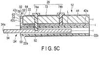
- the first slide lever 74a is located closest to the distal side in the slot 72, and the second slide lever 74b is located closest to the proximal side, as shown in FIG. 5C . That is, the first treatment portion 32 is switched to the closed position, and the second treatment portion 34 is made to protrude relative to the distal end of the activation portion 42b of the first member 42 of the first treatment portion 32. This allows the second treatment portion 34 to protrude to the distal side along the longitudinal axis L relative to the first member 42 of the first treatment portion 32.
- the user While the user performs treatment using the treatment instrument 12 when the treatment region 24 is arranged at an appropriate position, the user moves the first and second slide levers 74a and 74b of the movement mechanism 26 to the state shown in FIG. 5A or the state shown in FIG. 5C .
- the second treatment portion 34 incises a living tissue such as a membrane or peels tissue layers which is in contact with the second treatment portion 34.
- the user moves the first and second slide levers 74a and 74b to the state shown in FIG. 5B to switch the first treatment portion 32 to the open position and pull the second treatment portion 34 into the channel 92 relative to the first treatment portion 32.
- the blood vessel is arranged between the first contact surface 52 of the first member 42 of the first treatment portion 32 and the second contact surface 62 of the second treatment portion 34.
- the user moves the first and second slide levers 74a and 74b to the state shown in FIG. 5A or 5C to switch the first treatment portion 32 to the closed position, the blood vessel is brought into contact with both the first contact surface 52 of the first member 42 and the second contact surface 62 of the second member 44.
- the user presses the first switch 16a of the foot switch 16 to perform bipolar treatment on a living tissue as a treatment target such as a blood vessel using the first treatment portion 32, thus sealing the blood vessel.
- the second treatment portion 34 can be accommodated in the first treatment portion 32, as shown in FIGS. 5A and 5B . This can prevent the second treatment portion 34 from becoming an obstruction.
Landscapes
- Health & Medical Sciences (AREA)
- Surgery (AREA)
- Engineering & Computer Science (AREA)
- Life Sciences & Earth Sciences (AREA)
- Biomedical Technology (AREA)
- Otolaryngology (AREA)
- Nuclear Medicine, Radiotherapy & Molecular Imaging (AREA)
- Plasma & Fusion (AREA)
- Physics & Mathematics (AREA)
- Heart & Thoracic Surgery (AREA)
- Medical Informatics (AREA)
- Molecular Biology (AREA)
- Animal Behavior & Ethology (AREA)
- General Health & Medical Sciences (AREA)
- Public Health (AREA)
- Veterinary Medicine (AREA)
- Surgical Instruments (AREA)
Abstract
Description
- This invention relates a treatment instrument.
- For example, Jpn. Pat. Appln. KOKAI Publication No.
2001-61848 - The treatment instrument disclosed in Jpn. Pat. Appln. KOKAI Publication No.
2001-61848 2001-61848 - The present invention has as its object to provide a treatment instrument which can coagulate a living tissue and perform appropriate treatment such as incising and peeling the living tissue without interchanging with another treatment instrument.
- According to one aspect of the present invention, a treatment instrument includes: a sheath which defines a longitudinal axis with a distal end and a proximal end; a first treatment portion which includes a first member including a first contact surface coming into contact with a living tissue and a second member including a second contact surface facing the first contact surface and coming into contact with the living tissue at a position closer to a proximal side than the first contact surface along the longitudinal axis and which is configured to coagulate the living tissue by applying energy to the living tissue sandwiched between the first contact surface and the second contact surface; a movement mechanism which is configured to move at least one of the first member and the second member along the longitudinal axis and to switch between a closed position where the first contact surface is close to the second contact surface and an open position where the first contact surface is separate from the second contact surface; and a second treatment portion which is juxtaposed to the first treatment portion, wherein a distal end of the second treatment portion is located at a position closer to a distal side along the longitudinal axis than a distal end of the first treatment portion when the first contact surface and the second contact surface are located at the closed position, and the distal end of the second treatment portion is located at the same position as the position of the distal end of the first treatment portion or located closer to the proximal side than the distal end of the first treatment portion when the first contact surface and the second contact surface are located at the open position.
-
-
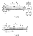
FIG. 1A is a schematic view showing a treatment system according to the first embodiment while a first treatment portion is closed and a distal end of a second treatment portion is made to protrude relative to the first treatment portion toward a distal side along a longitudinal axis. -
FIG. 1B is a schematic view showing a treatment instrument according to the first embodiment while the first treatment portion is open and the distal end of the second treatment portion is arranged on a proximal side along the longitudinal axis relative to a first contact surface of the first treatment portion. -
FIG. 2A is a schematic view showing a treatment system according to the first modification of the first embodiment while the first treatment portion is closed and the distal end of the second treatment portion is made to protrude relative to the first treatment portion toward the distal side along the longitudinal axis. -
FIG. 2B is a schematic view showing the treatment instrument according to the first modification of the first embodiment while the first treatment portion is open and the distal end of the second treatment portion is arranged at almost the same position along the longitudinal axis as that of the first contact surface of the first treatment portion along the longitudinal axis. -
FIG. 3A is a schematic view showing the treatment instrument according to the second modification of the first embodiment while the first treatment portion is closed and the distal end of the second treatment portion is made to protrude relative to the first treatment portion toward the distal side along the longitudinal axis. -
FIG. 3B is a schematic view showing the treatment instrument according to the second modification of the first embodiment when seen from the direction of anarrow 3B inFIG. 3A . -
FIG. 4A is a schematic view showing a treatment instrument according to a second embodiment while a first treatment portion is appropriately open and a distal end of a second treatment portion is made to protrude relative to the first treatment portion toward a distal side along the longitudinal axis. -
FIG. 4B is a schematic view showing a treatment instrument according to the second embodiment while the first treatment portion is open and the distal end of the second treatment portion is arranged at almost the same position along the longitudinal axis as that of a first contact surface of the first treatment portion along the longitudinal axis. -
FIG. 4C is a schematic view showing the treatment instrument according to the second embodiment while the first treatment portion is closed and the distal end of the second treatment portion is arranged at almost the same position along the longitudinal axis as that of the first contact surface of the first treatment portion along the longitudinal axis. -
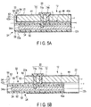
FIG. 5A is a schematic view showing a state in which the movement mechanism of a treatment instrument according to a third embodiment is operated to switch a first treatment portion in a treatment region to a closed position, and a second treatment portion is pulled into the first treatment portion. -
FIG. 5B is a schematic view showing a state in which the movement mechanism of the treatment instrument according to the third embodiment is operated to switch the first treatment portion in the treatment region to an open position, and the second treatment portion is pulled into the first treatment portion. -
FIG. 5C is a schematic view showing a state in which the movement mechanism of the treatment instrument according to the third embodiment is operated to switch the first treatment portion in the treatment region to the closed position, and the second treatment portion is made to protrude relative to the distal end of the first treatment portion. - Hereinafter, embodiments of this invention will be described with reference to the drawings.
- The first embodiment will be described with reference to
FIGS. 1A and 1B . - As shown in
FIG. 1A , a treatment system (treatment instrument unit) 10 according to this embodiment includes atreatment instrument 12 and acontroller 14. In this case, afoot switch 16 is connected to thecontroller 14. A hand switch (not shown) can be provided on thetreatment instrument 12 together with or instead of thefoot switch 16. A patient plate P is also connected to thecontroller 14. - As shown in
FIGS. 1A and 1B , thetreatment instrument 12 includes atubular sheath 22, atreatment region 24 protruding from adistal end 22a of thesheath 22, and amovement mechanism 26. A longitudinal axis L is defined by thedistal end 22a and aproximal end 22b of thesheath 22. Thesheath 22 has electrical insulation properties. Thetreatment region 24 includes afirst treatment portion 32 and asecond treatment portion 34. Referring toFIGS. 1A to 2B , a distal portion of thesecond treatment portion 34 has a straight shape but is not specifically limited. It is possible to use thesecond treatment portion 34 having a distal portion formed into an appropriate shape such as a hook-like shape or spatula-like shape. - In this embodiment, the
first treatment portion 32 can perform bipolar treatment. Thefirst treatment portion 32 includes afirst member 42 and asecond member 44. Thefirst member 42 and thesecond member 44 each are preferably formed from a metal material having electrical conductivity. Note that thefirst member 42 and thesecond member 44 may be formed from the same material or different materials. Both thefirst member 42 and thesecond member 44 are electrically connected to thecontroller 14. - In this embodiment, the
first member 42 includes ashaft 42a extending, for example, parallel to the longitudinal axis L and anactivation portion 42b obtained by bending the distal end of theshaft 42a in a direction crossing the longitudinal axis L. Theactivation portion 42b is bent in, for example, an almost L shape. Referring toFIGS. 1A to 2B , the angle of theactivation portion 42b relative to theshaft 42a is 90°. However, theactivation portion 42b may be bent at an appropriate angle other than 90°. Obviously, the portion betweenportions 54 and 58 (to be described later), i.e., the boundary portion between theshaft 42a and theactivation portion 42b, is preferably formed into a curved surface by, for example, being chamfered. Likewise, obviously, the boundary portion betweensurfaces shaft 42a of thefirst member 42, thesecond member 44 extends, for example, parallel to the longitudinal axis L and is formed into, for example, a columnar rod. - The
activation portion 42b of thefirst member 42 includes afirst contact surface 52 which treats a living tissue while being in contact with the living tissue. Theactivation portion 42b of thefirst member 42 protrudes relative to thedistal end 22a of thesheath 22. Thefirst contact surface 52 is directed toward thedistal end 22a of thesheath 22. That is, thefirst contact surface 52 is directed toward the proximal side along the longitudinal axis L. - The
second member 44 includes asecond contact surface 62 which is located at a proximal side along the longitudinal axis L than thefirst contact surface 52, which is directed toward thefirst contact surface 52, and which treats a living tissue, together with thefirst contact surface 52, while being in contact with the living tissue. Thesecond contact surface 62 is directed toward the distal side along the longitudinal axis L. Thefirst contact surface 52 is preferably parallel to thesecond contact surface 62. - Obviously, the
first contact surface 52 and thesecond contact surface 62 need not always be directed along the longitudinal axis L, and normal lines to thefirst contact surface 52 and thesecond contact surface 62 are preferably formed into slopes shifted from the longitudinal axis L. - In this embodiment, the
first contact surface 52 and thesecond contact surface 62 each are used as a high-frequency electrode. Thefirst contact surface 52 and thesecond contact surface 62 of thefirst treatment portion 32 can perform bipolar treatment that can coagulate a living tissue by, for example, sealing the living tissue sandwiched between thefirst contact surface 52 and thesecond contact surface 62 by applying energy to the sandwiched living tissue. When the living tissue is a blood vessel, the sandwiched blood vessel is sealed by bipolar treatment. - The
first member 42 includes the electrical insulatingportion 54 which prevents treatment on a living tissue when energy is applied while being in contact with the living tissue. The electrical insulatingportion 54 is formed from, for example, an insulating coating. The electrical insulatingportion 54 preferably has heat resistance. The electrical insulatingportion 54 is formed on the surface reverse to thefirst contact surface 52. That is, the electrical insulatingportion 54 is located on the distal end surface of thefirst member 42 and directed toward the distal side along the longitudinal axis L. - The
portion 56, of theshaft 42a of thefirst member 42, which is located near the boundary with theactivation portion 42b and also near the distal end of thesecond member 44 may be formed as an electrode like thefirst contact surface 52 or may be formed as an electrical insulating portion. The electrical insulatingportion 58 is formed on the reverse surface (far face) of theportion 56. The electrical insulatingportions portion 58 is formed from, for example, an insulating coating. In addition to the electrical insulatingportion 54, the electrical insulatingportion 58 offirst member 42 prevents treatment on a living tissue when the above energy is applied while being in contact with the living tissue. - The side surfaces between the
first contact surface 52 and the electrical insulatingportion 54, the side surfaces between theportion 56 and the electrical insulatingportion 58, and afar end 42c of theactivation portion 42b of thefirst member 42 relative to theshaft 42a elongated along the longitudinal axis L are preferably formed as electrical insulatingportions 59. Note that thefar end 42c forms an opening inlet in which a living tissue is arranged between thefar end 42c and thesecond contact surface 62 of thesecond member 44. - The
second member 44 includes an electrical insulatingportion 64 which prevents treatment on a living tissue when energy is applied while being in contact with the living tissue. The electrical insulatingportion 64 is formed on a portion other than thesecond contact surface 62. More specifically, an insulating coating is applied to the outer circumferential surface of the portion, of thesecond member 44, which is located around the longitudinal axis. For this reason, the sliding surface between thefirst member 42 and thesecond member 44 is electrically insulated. Note that the electrical insulatingportion 64 preferably has heat resistance. - The
first member 42 shown inFIGS. 1A and 1B is fixed to thesheath 22. Thesecond member 44 can move along the longitudinal axis L relative to thesheath 22. Themovement mechanism 26 can move thesecond member 44 within a predetermined range along the longitudinal axis L. As themovement mechanism 26, an appropriate mechanism can be used. For example, themovement mechanism 26 as a linear motor can be used to move thesecond member 44 within a predetermined range along the longitudinal axis L relative to thesheath 22. Briefly described below is an example of themovement mechanism 26 with which the user manually moves thesecond member 44 along the longitudinal axis L relative to thesheath 22. - The
sheath 22 is provided with aslot 72 which is formed longer along the longitudinal axis L than in the circumferential direction of the longitudinal axis L and defines a movement range in which thesecond member 44 is moved along the longitudinal axis L. Theslot 72 is provided with a slide lever (slider) 74 as an operation member. Theslide lever 74 can move between the distal end and proximal end of theslot 72 along the longitudinal axis L. Theslide lever 74 has electrical insulation properties. Theslide lever 74 is coupled to thesecond member 44. That is, for example, themovement mechanism 26 includes theslot 72 formed in thesheath 22 and theslide lever 74 coupled to thesecond member 44. - When the user moves the
slide lever 74 toward the distal side of thesheath 22 along the longitudinal axis L, themovement mechanism 26 can bring theslide lever 74 into contact with the distal end of theslot 72. When the user moves theslide lever 74 toward the proximal side of thesheath 22 along the longitudinal axis L, themovement mechanism 26 can bring theslide lever 74 into contact with the proximal end of theslot 72. In this manner, theslot 72 can define the movable range of theslide lever 74. - When the user brings the
slide lever 74 into contact with the distal end of theslot 72 of thesheath 22 along the longitudinal axis L, thefirst contact surface 52 of thefirst member 42 separates from thesecond contact surface 62 of thesecond member 44. This sets the open position where thefirst contact surface 52 of thefirst member 42 is separate from thesecond contact surface 62 of thesecond member 44. When the user brings theslide lever 74 into contact with the proximal end of theslot 72 of thesheath 22 along the longitudinal axis L, thefirst contact surface 52 of thefirst member 42 approaches thesecond contact surface 62 of thesecond member 44. This sets the closed position where thefirst contact surface 52 of thefirst member 42 is close to thesecond contact surface 62 of thesecond member 44. At this time, thefirst contact surface 52 is not in contact with thesecond contact surface 62, and a slight gap is formed between them. Operating theslide lever 74 can adjust the opening amount by adjusting the distance between thefirst contact surface 52 and thesecond contact surface 62. That is, themovement mechanism 26 moves thefirst member 42 along the longitudinal axis L to switch between the closed position where thefirst contact surface 52 is close to thesecond contact surface 62 and the open position where thefirst contact surface 52 is separate from thesecond contact surface 62. - The
second treatment portion 34 is formed into a rod-like shape thinner than thesecond member 44.FIGS. 1A to 2B show thesecond treatment portion 34 extending straight along the longitudinal axis L. As described above, however, thesecond treatment portion 34 can have any appropriate shape. Thesecond treatment portion 34 is used as, for example, a high-frequency electrode. Thesecond treatment portion 34 can perform bipolar treatment to incise and peel a living tissue between thesecond treatment portion 34 and the patient plate P attached to the patient by applying energy to the living tissue in contact with thesecond treatment portion 34. - The
second treatment portion 34 is juxtaposed to thefirst treatment portion 32. When thefirst treatment portion 32 is switched to the closed position, thesecond treatment portion 34 is located at the distal side along the longitudinal axis L than the electrical insulatingportion 54 of the distal end surface of thefirst treatment portion 32. When thefirst contact surface 52 and thesecond contact surface 62 are located at the closed position, thesecond treatment portion 34 is located at the distal side along the longitudinal axis L than thefirst treatment portion 32, and thesecond treatment portion 34 can incise or peel the living tissue by applying energy to the living tissue. - When the
first treatment portion 32 is switched to the open position, thesecond treatment portion 34 is located at the same position as that of the distal end of thefirst treatment portion 32 or located at the proximal side than the distal end of thefirst treatment portion 32. When thefirst treatment portion 32 is switched to the open position, thesecond treatment portion 34 is located at the same position as that of thefirst contact surface 52 of thefirst treatment portion 32 along the longitudinal axis L or located at the proximal side than thefirst contact surface 52 of thefirst treatment portion 32. - Note that the
first treatment portion 32 and thesecond treatment portion 34 are not electrically connected to each other and are electrically insulated. Thefirst treatment portion 32 and thesecond treatment portion 34 are electrically insulated also by an insulating coating or the like. - In this embodiment, the
controller 14 can perform control to perform bipolar treatment using thefirst treatment portion 32 by outputting energy to thefirst treatment portion 32 in accordance with, for example, an instruction from thefoot switch 16, and can also perform control to cause thesecond treatment portion 34 to perform monopolar treatment using thesecond treatment portion 34 by outputting energy to thesecond treatment portion 34. - The
foot switch 16 of thetreatment system 10 according to this embodiment includes afirst switch 16a and asecond switch 16b. Thefirst switch 16a outputs, in accordance with a pressing operation, an instruction to output energy from thecontroller 14 when thefirst treatment portion 32 performs bipolar treatment. Thesecond switch 16b outputs an instruction to output energy when thesecond treatment portion 34 performs monopolar treatment. - The effects of the
treatment system 10 according to this embodiment will be briefly described next. For example, thetreatment instrument 12 is used together with an endoscope (not shown) via a trocar. - The user attaches the patient plate P to an appropriate location on a patient. The user appropriately holds the
treatment instrument 12 and causes thetreatment region 24 to face a membrane tissue or layered tissue in the body while checking an observation image of the endoscope. Thesecond treatment portion 34 of thetreatment region 24 has a thin shape, and hence can maintain approachability to the membrane tissue or the layered tissue in the body. - As shown in
FIG. 1A , thefirst treatment portion 32 is set at the closed position, and thedistal end 34a of thesecond treatment portion 34 is made to protrude toward the distal side along the longitudinal axis L relative to the distal end of thefirst treatment portion 32. The user presses thesecond switch 16b to cause thesecond treatment portion 34 of thetreatment region 24 to perform monopolar treatment on the living tissue. Thesecond treatment portion 34 incises a living tissue as a treatment target or peels tissue layers which is in contact with thesecond treatment portion 34, by applying monopolar high-frequency energy to the living tissue and recovers a high-frequency current via the patient plate P attached to the patient. Note that the user presses thesecond switch 16b only when actually performing treatment such as incision, and normally keeps thesecond switch 16b unpressed. - The
first treatment portion 32 and thesecond treatment portion 34 are electrically insulated. For this reason, in monopolar treatment using thesecond treatment portion 34, no current flows in thefirst treatment portion 32. When the electrical insulatingportions first treatment portion 32 come into contact with a living tissue at an appropriate position, no current flows in the living tissue in contact with the portions. This prevents a high-frequency current from accidentally flowing from the electrical insulatingportions first treatment portion 32 to the living tissue. That is, this prevents thetreatment region 24 from performing unintended treatment. - When repeatedly incising a filmy living tissue or peels tissue layers, a blood vessel is sometimes exposed. In this case, the
second treatment portion 34 seals the blood vessel, that is, coagulates the blood vessel, to prevent bleeding from the blood vessel. - More specifically, the user operates the
slide lever 74 along theslot 72 to switch thefirst contact surface 52 of thefirst member 42 and thesecond contact surface 62 of thesecond member 44 to the open position, as shown inFIG. 1B . The distal end of thefirst treatment portion 32 is protruded from thedistal end 34a of thesecond treatment portion 34. More specifically, thefirst contact surface 52 of thefirst treatment portion 32 is protruded from thedistal end 34a of thesecond treatment portion 34. This makes it difficult for thedistal end 34a of thesecond treatment portion 34 to obstruct, for example, the operation of bringing the blood vessel into contact with thefirst contact surface 52 of thefirst member 42. In this state, the blood vessel is arranged between thefirst contact surface 52 of thefirst member 42 of thefirst treatment portion 32 and thesecond contact surface 62 of thesecond treatment portion 34. - As shown in
FIG. 1A , the user moves theslide lever 74 to switch thefirst contact surface 52 of thefirst member 42 and thesecond contact surface 62 of thesecond member 44 to the closed position. At this time, the blood vessel comes into contact with both thefirst contact surface 52 of thefirst member 42 and thesecond contact surface 62 of thesecond member 44. Thefirst contact surface 52 is not electrically connected to thesecond contact surface 62. In this state, the user presses thefirst switch 16a to cause thefirst treatment portion 32 to perform bipolar treatment on a living tissue as a treatment target such as a blood vessel. The blood vessel (living tissue) as a treatment target which is in contact with both thefirst contact surface 52 of thefirst member 42 of thefirst treatment portion 32 and thesecond contact surface 62 of thesecond member 44 is coagulated by Joule heat on applying high-frequency energy to the blood vessel. This prevents bleeding from the coagulated portion. When incising the blood vessel, the user switches thefirst treatment portion 32 to the open position to release the blood vessel and then switches the portion to the closed position. The coagulated portion of the blood vessel is incised by thesecond treatment portion 34. At this time, the user is only required to move thetreatment region 24 and need not interchange thetreatment instrument 12 itself by, for example, removing it from the trocar. - Note that when the user switches the
first treatment portion 32 from the open position to the closed position or from the closed position to the open position, thefirst member 42 and thesecond member 44 only move back and forth relatively. This leads to a simple structure, which is less likely to degrade visibility when a blood vessel or the like is arranged between thefirst contact surface 52 of thefirst member 42 and thesecond contact surface 62 of thesecond member 44. - Subsequently, as the user performs monopolar treatment such as incision using the
second treatment portion 34, the user performs bipolar treatment using thefirst treatment portion 32 if, for example, the blood vessel is exposed. If necessary, the user performs monopolar treatment using thesecond treatment portion 34 to, for example, incise the blood vessel sealed by bipolar treatment, thus finishing the desired treatment. - As described above, the
treatment instrument 12 according to this embodiment has the following effects. - When the
first contact surface 52 and thesecond contact surface 62 are located at the closed position, thedistal end 34a of thesecond treatment portion 34 is located closer to the distal side along the longitudinal axis L than the distal end of thefirst treatment portion 32. This enables thesecond treatment portion 34 to perform treatment such as incision or peeling, as needed, with respect to a living tissue as a treatment target while thefirst treatment portion 32 is located at the closed position. - When the
first contact surface 52 and thesecond contact surface 62 are located at the open position, thedistal end 34a of thesecond treatment portion 34 is located at the same position as that of the distal end of thefirst treatment portion 32 or located closer to the proximal side than the distal end of thefirst treatment portion 32. Even if, for example, a blood vessel is exposed, when thefirst treatment portion 32 is switched to the open position, the distal end of thefirst treatment portion 32, specifically, thefirst contact surface 52 is able to be arranged closer to the distal side than thedistal end 34a of thesecond treatment portion 34. Thus, it is easy to bring the blood vessel into contact with thefirst contact surface 52. When the blood vessel is arranged on thefirst contact surface 52, it is easy to bring the blood vessel into contact with both thefirst contact surface 52 and thesecond contact surface 62 while being less likely to be influenced by the presence of thesecond treatment portion 34. When thefirst treatment portion 32 is located at the closed position, thedistal end 34a of thesecond treatment portion 34 is located closer to the distal side along the longitudinal axis L than the distal end of thefirst treatment portion 32; however, when thefirst treatment portion 32 is switched to the open position, a part of thefirst treatment portion 32 is located closer to the distal side along the longitudinal axis L than thedistal end 34a of thesecond treatment portion 34. Therefore, using thetreatment instrument 12 according to this embodiment makes it easy for the user to perform treatment such as sealing a living tissue such as a blood vessel, as needed, using thefirst treatment portion 32. - After the blood vessel is sealed, the user can proceed with treatment such as incising or peeling a living tissue as a treatment target using the
second treatment portion 34 while maintaining a state in which thetreatment region 24 is located close to the living tissue as the treatment target. The user can therefore proceed with treatment on a living tissue as a treatment target using onetreatment instrument 12 while maintaining a state in which thetreatment region 24 is located close to the living tissue without interchanging the treatment instrument. This can shorten the treatment time and greatly improve the treatment efficiency of a living tissue as a treatment target by using thetreatment instrument 12. - When, for example, using the
treatment instrument 12 together with an endoscope, there is no need to interchange thetreatment instrument 12. This makes it possible to always keep thetreatment region 24 close a treatment target while arranging thetreatment region 24 within the observation field of view of the endoscope. For this reason, once the user set thetreatment region 24 within the field of view of the endoscope, it is not necessary to arrange thetreatment region 24 within the field of view of the endoscope again. That is, once the user makes thetreatment region 24 face a living tissue as a treatment target, he/she can proceed with treatment while thetreatment region 24 is arranged within the field of view of the endoscope. - Note that the
treatment system 10 according to this embodiment has been described by exemplifying the case of performing monopolar treatment using thesecond treatment portion 34. Thesecond treatment portion 34 is formed thinner than thefirst treatment portion 32. For this reason, thesecond treatment portion 34 can perform more elaborate treatment than thefirst treatment portion 32. Thesecond treatment portion 34 can proceed with treatment on a living tissue without requiring the application of any energy from thecontroller 14, for example, separating an exposed blood vessel from the living tissue by hooking the blood vessel. - The
first contact surface 52 of thefirst member 42 can also be suitably used as a first heater (not shown) instead of a high-frequency electrode. Thesecond contact surface 62 of thesecond member 44 can also be suitably used as a second heater (not shown) instead of a high-frequency electrode. When thefirst contact surface 52 and thesecond contact surface 62 are not used as high-frequency electrodes in this manner, thefirst contact surface 52 and thesecond contact surface 62 may come into contact with each other. Note that the first and second heaters each are preferably formed into a plate-like shape which can raise temperature to about several hundred degrees Celsius in several sec. Thetreatment instrument 12 described here can be used in the same manner as thetreatment instrument 12 described in the first embodiment. Using the first and second heaters allows thefirst treatment portion 32 to perform treatment of coagulating a living tissue or sealing a blood vessel. In addition, using the first and second heaters can incise the living tissue as well as coagulating it, depending on an energy amount setting. In this manner, energy used for treatment using thetreatment instrument 12 is not limited to high-frequency energy, and thermal energy can be used as needed. - Note that the
treatment instrument 12 may include at least one of the first and second heaters. - The
first contact surface 52 of thefirst treatment portion 32 may be formed as an electrode, while the first heater may be embedded in thefirst contact surface 52. Thesecond contact surface 62 of thefirst treatment portion 32 may be formed as an electrode, while the second heater may be embedded in thesecond contact surface 62. That is, thefirst contact surface 52 and thesecond contact surface 62 of thefirst treatment portion 32 are used both as high-frequency electrodes and heaters. In this case, thefirst contact surface 52 and thesecond contact surface 62 are inhibited from coming into contact with each other. A living tissue such as a blood vessel can be coagulated or incised by thermal energy from the heaters while the living tissue is coagulated by high-frequency energy. For example, it takes much time to seal a relatively thick blood vessel or the like using high-frequency energy. However, using both high-frequency energy and thermal energy from the heaters can improve the treatment performance and shorten the time required for sealing the blood vessel. - In addition, heat transfer from the heaters can be used with respect to the
second treatment portion 34 instead of performing monopolar high-frequency energy treatment. Using heat transfer can also perform treatment similar to that using high-frequency energy, for example, incision of a living tissue or peeling of tissue layers. - The first modification of the first embodiment will be described next with reference to
FIGS. 2A and 2B . - As shown in
FIGS. 2A and 2B , thesecond member 44 is fixed to the distal end of thesheath 22. Thesecond member 44 includes first and second throughholes holes shaft 42a of thefirst member 42 extends through the first throughhole 44a. Thesecond treatment portion 34 extends through the second throughhole 44b. Thefirst member 42 of thefirst treatment portion 32 is electrically insulated from thesecond member 44 of thefirst treatment portion 32. Thesecond treatment portion 34 is electrically insulated from thesecond member 44 of thefirst treatment portion 32. - A
first switch 18a and asecond switch 18b are provided on the outer circumferential surface of thesheath 22. When, for example, thefirst switch 18a is pressed by the user, thecontroller 14 outputs an instruction to output energy to perform bipolar treatment using thefirst treatment portion 32. In addition, when, for example, thesecond switch 18b is pressed by the user, thecontroller 14 outputs an instruction to output energy to perform monopolar treatment using thesecond treatment portion 34. Obviously, in addition to operating theswitches foot switch 16 can also perform energy output control. - The
treatment instrument 12 according to this modification can be used in the same manner as thetreatment instrument 12 described in the first embodiment, and hence a description of effects will be omitted. - The second modification of the first embodiment will be described next with reference to
FIGS. 3A and 3B . - As shown in
FIG. 3A , thesecond member 44 is fixed to the distal end of thesheath 22. Thesecond member 44 has a throughhole 44a. The throughhole 44a is preferably provided with an insulating coating. Theshaft 42a of thefirst member 42 of thefirst treatment portion 32 extends through the throughhole 44a. - As shown in
FIG. 3B , a channel (concave surface) 43 is formed in theshaft 42a of thefirst member 42 of thefirst treatment portion 32. Thechannel 43 is formed into an almost U-shape when seen in a cross-section perpendicular to the longitudinal axis L. Thechannel 43 extends from the distal end to the proximal end of theshaft 42a. Thechannel 43 is preferably provided with an insulating coating. Thechannel 43 is provided with thesecond treatment portion 34. Thefirst member 42 of thefirst treatment portion 32 is electrically insulated from thesecond member 44 of thefirst treatment portion 32. Thesecond treatment portion 34 is electrically insulated from thefirst member 42 and thesecond member 44 of thefirst treatment portion 32. - The
treatment instrument 12 according to this modification can be used in the same manner as thetreatment instrument 12 described in the first embodiment, and hence a description of effects will be omitted. - Although the
channel 43 has been described as having a U shape, it is obvious that thechannel 43 can be formed into a tubular channel. In addition, when, for example, the distal portion of thesecond treatment portion 34 has a hook shape, the distal end of thechannel 43, i.e., the distal end surface of thefirst member 42 of thefirst treatment portion 32 preferably has a slot having a shape which can accommodate the distal portion of thesecond treatment portion 34. - The second embodiment will be described next with reference to
FIGS. 4A to 4C . This embodiment is a modification of the first embodiment including each modification. When possible, the same reference numerals as those in the first embodiment denote the same members or members having the same functions as in the second embodiment, and a detailed description of them will be omitted. - As shown in
FIGS. 4A to 4C , aslide lever 74 is not fixed to afirst member 42 of afirst treatment portion 32 but is fixed to asecond member 44. - As shown in
FIG. 4A , thefirst member 42 and thesecond member 44 of thefirst treatment portion 32 are coupled to each other through an energizingmember 46. The portion of thesecond member 44 which is coupled to the energizingmember 46 preferably has electrical insulation properties. For this reason, thefirst member 42 and thesecond member 44 are electrically insulated from each other. Note that the energizingmember 46 itself is preferably formed from a material having electrical insulation properties. As the energizingmember 46, for example, a compression spring such as a compression coil spring is preferably used. For this reason, the energizingmember 46 separates afirst contact surface 52 of thefirst member 42 from asecond contact surface 62 of thesecond member 44 of thefirst treatment portion 32. - The effects of a
treatment instrument 12 according to this embodiment will be described next. - As shown in
FIG. 4A , theslide lever 74 is arranged at the proximal end of theslot 72. In this case, anengagement portion 48 of thefirst member 42 is located at the proximal side along a longitudinal axis L than thedistal end 22a of thesheath 22. In this case, thedistal end 34a of thesecond treatment portion 34 protrudes toward the distal side along the longitudinal axis L relative to the distal end of thefirst treatment portion 32. For example, thesecond treatment portion 34 can perform monopolar treatment such as incising a living tissue or peeling tissue layers. - If, for example, a blood vessel is exposed due to treatment using the
second treatment portion 34, the user moves theslide lever 74 from the proximal end to the distal end of theslot 72, as shown inFIG. 4B . Thesecond contact surface 62 of thesecond member 44 moves toward the distal side along the longitudinal axis L. At this time, the energizing force of the energizingmember 46 moves thefirst member 42 toward the distal side along the longitudinal axis L in conjunction with thesecond member 44. That is, the energizingmember 46 can move thefirst member 42 and thesecond member 44 together. The energizingmember 46 then keeps thefirst contact surface 52 of thefirst member 42 of thefirst treatment portion 32 separated from thesecond contact surface 62 of thesecond member 44. - When the user moves the
slide lever 74 from the proximal end to the distal end of theslot 72, theengagement portion 48 of thefirst member 42 engages with thedistal end 22a of thesheath 22. At this time, thefirst contact surface 52 of thefirst member 42 is located at almost the same position as that of thedistal end 34a of thesecond treatment portion 34 or located at the distal side than thedistal end 34a of thesecond treatment portion 34. In this state, for example, a blood vessel is brought into contact with thefirst contact surface 52. - When the user further moves the
slide lever 74 from the proximal end to the distal end of theslot 72, thefirst member 42 engages with thesheath 22 via theengagement portion 48 and is restricted from moving toward the distal side along the longitudinal axis L. The operating force applied to theslide lever 74 by the user moves thesecond member 44 toward the distal side along the longitudinal axis L against the energizing force of the energizingmember 46. - As shown in
FIG. 4C , when the user moves theslide lever 74 toward the distal end of theslot 72, thesecond contact surface 62 of thesecond member 44 approaches thefirst contact surface 52 of thefirst member 42 against the energizing force of the energizingmember 46 while the position of thefirst member 42 relative to thedistal end 22a of thesheath 22 is maintained. Theslide lever 74 allows thesecond contact surface 62 of thesecond member 44 to approach thefirst contact surface 52 of thefirst member 42 as thefirst member 42 moves from the proximal side to the distal side along the longitudinal axis L against the energizing force of the energizingmember 46 while engaging with thesheath 22 via theengagement portion 48. That is, themovement mechanism 26 according to this embodiment moves thesecond member 44 along the longitudinal axis L and can switch between the closed position where thefirst contact surface 52 is close to thesecond contact surface 62 and the open position where thefirst contact surface 52 is separate from thesecond contact surface 62. This allows thefirst treatment portion 32 to perform bipolar treatment on a blood vessel. Thefirst treatment portion 32 can therefore seal a blood vessel or the like. - In this manner, when the user operates only the
single slide lever 74, both of thefirst member 42 and thesecond member 44 can move relative to thesheath 22. Thesecond member 44 can be made to approach thefirst member 42 by operating theslide lever 74 in accordance with the intention of the user from a state in which thefirst member 42 engages with thedistal end 22a of thesheath 22. For this reason, only moving theslide lever 74 relative to thesheath 22 can move thesecond member 44 along the longitudinal axis L and perform appropriate treatment using thefirst treatment portion 32 while thefirst member 42 is positioned. - This embodiment has exemplified the case in which one end of the energizing
member 46 is coupled to thefirst member 42, and the other end is coupled to thesecond member 44. Even if, however, one end of the energizingmember 46 is coupled to thefirst member 42 and the other end is coupled to the slide lever (slider) 74, thefirst member 42 and thesecond member 44 can be moved in the same manner as described above. - The third embodiment will be described with reference to
FIGS. 5A to 5C . This embodiment is a modification of the first and second embodiments. When possible, the same reference numerals as those in the first and embodiments denote the same members or members having the same functions as in the third embodiment, and a detailed description of them will be omitted. - The first embodiment has exemplified the case in which the
first contact surface 52 of thefirst member 42 can be located at the same position as that of thedistal end 34a of thesecond treatment portion 34 or located closer to the distal side than thedistal end 34a of thesecond treatment portion 34 by moving thefirst member 42 of thefirst treatment portion 32 relative to thedistal end 22a of thesheath 22 along the longitudinal axis L. The second embodiment has exemplified the case in which thefirst contact surface 52 of thefirst member 42 can be located at the same position as that of thedistal end 34a of thesecond treatment portion 34 or located closer to the distal side than thedistal end 34a of thesecond treatment portion 34 by moving thefirst member 42 and thesecond member 44 of thefirst treatment portion 32 relative to thedistal end 22a of thesheath 22 along the longitudinal axis L. - As shown in
FIGS. 5A to 5C , thesecond treatment portion 34 may be made movable relative to thedistal end 22a of thesheath 22 along the longitudinal axis L. That is, the amount of protrusion of thedistal end 34a of thesecond treatment portion 34 relative to thedistal end 22a of thesheath 22 may be made adjustable. This also makes it possible to locate thefirst contact surface 52 of thefirst member 42 of thefirst treatment portion 32 at the same position as that of thedistal end 34a of thesecond treatment portion 34 or at a position closer to the distal side than thedistal end 34a of thesecond treatment portion 34. - The
first member 42 of thefirst treatment portion 32 includes achannel 92 formed parallel to the longitudinal axis L and having an insulated inner circumferential surface. In this case, thechannel 92 is formed in the surface reverse to aportion 56. - A
movement mechanism 26 includes theslot 72, thefirst slide lever 74a, and asecond slide lever 74b. Theslot 72 is commonly used for thefirst slide lever 74a and thesecond slide lever 74b. Thefirst slide lever 74a is arranged closer to the distal side in theslot 72 along the longitudinal axis L than thesecond slide lever 74b. Thefirst slide lever 74a is coupled to thesecond treatment portion 34. Thesecond slide lever 74b is coupled to theshaft 42a of thefirst member 42 of thefirst treatment portion 32. - When no treatment is to be performed, the
first slide lever 74a and thesecond slide lever 74b are located closest to the proximal side in theslot 72, as shown inFIG. 5A . That is, thefirst treatment portion 32 is switched to the closed position, and thesecond treatment portion 34 is located closer to the proximal side than the distal end of theactivation portion 42b of thefirst member 42 of thefirst treatment portion 32. - When the
first treatment portion 32 seals a blood vessel or the like, thefirst slide lever 74a and thesecond slide lever 74b are located closest to the distal side in theslot 72, as shown inFIG. 5B . That is, thefirst treatment portion 32 is switched to the open position, and thesecond treatment portion 34 is located closer to the proximal side than the distal end of theactivation portion 42b of thefirst member 42 of thefirst treatment portion 32. - When the
second treatment portion 34 incises a membrane or peels a living tissue, thefirst slide lever 74a is located closest to the distal side in theslot 72, and thesecond slide lever 74b is located closest to the proximal side, as shown inFIG. 5C . That is, thefirst treatment portion 32 is switched to the closed position, and thesecond treatment portion 34 is made to protrude relative to the distal end of theactivation portion 42b of thefirst member 42 of thefirst treatment portion 32. This allows thesecond treatment portion 34 to protrude to the distal side along the longitudinal axis L relative to thefirst member 42 of thefirst treatment portion 32. - While the user performs treatment using the
treatment instrument 12 when thetreatment region 24 is arranged at an appropriate position, the user moves the first and second slide levers 74a and 74b of themovement mechanism 26 to the state shown inFIG. 5A or the state shown inFIG. 5C . - The user then moves the first and second slide levers 74a and 74b to the state shown in
FIG. 5C , and makes thesecond treatment portion 34 protrude relative to the distal end of theactivation portion 42b of thefirst member 42 of thefirst treatment portion 32. In this state, for example, the user presses thesecond switch 16b of thefoot switch 16 to perform monopolar treatment on a living tissue using thesecond treatment portion 34 of thetreatment region 24. Thesecond treatment portion 34 incises a living tissue such as a membrane or peels tissue layers which is in contact with thesecond treatment portion 34. - If, for example, a blood vessel is exposed, the user moves the first and second slide levers 74a and 74b to the state shown in
FIG. 5B to switch thefirst treatment portion 32 to the open position and pull thesecond treatment portion 34 into thechannel 92 relative to thefirst treatment portion 32. In this state, the blood vessel is arranged between thefirst contact surface 52 of thefirst member 42 of thefirst treatment portion 32 and thesecond contact surface 62 of thesecond treatment portion 34. When the user moves the first and second slide levers 74a and 74b to the state shown inFIG. 5A or5C to switch thefirst treatment portion 32 to the closed position, the blood vessel is brought into contact with both thefirst contact surface 52 of thefirst member 42 and thesecond contact surface 62 of thesecond member 44. In this state, for example, the user presses thefirst switch 16a of thefoot switch 16 to perform bipolar treatment on a living tissue as a treatment target such as a blood vessel using thefirst treatment portion 32, thus sealing the blood vessel. - As described above, when, for example, the
first treatment portion 32 performs treatment, thesecond treatment portion 34 can be accommodated in thefirst treatment portion 32, as shown inFIGS. 5A and 5B . This can prevent thesecond treatment portion 34 from becoming an obstruction. - Hitherto, several embodiments have specifically be described with reference to the drawings, but this invention is not limited to the abovementioned embodiments, but includes all implementations to be performed without departing from the gist of the invention.
Claims (7)
- A treatment instrument comprising:a sheath which defines a longitudinal axis with a distal end and a proximal end;a first treatment portion which includes a first member including a first contact surface coming into contact with a living tissue and a second member including a second contact surface facing the first contact surface and coming into contact with the living tissue at a position closer to a proximal side than the first contact surface along the longitudinal axis and which is configured to coagulate the living tissue by applying energy to the living tissue sandwiched between the first contact surface and the second contact surface;a movement mechanism which is configured to move at least one of the first member and the second member along the longitudinal axis and to switch between a closed position where the first contact surface is close to the second contact surface and an open position where the first contact surface is separate from the second contact surface; anda second treatment portion which is juxtaposed to the first treatment portion, wherein a distal end of the second treatment portion is located at a position closer to a distal side along the longitudinal axis than a distal end of the first treatment portion when the first contact surface and the second contact surface are located at the closed position, and the distal end of the second treatment portion is located at the same position as the position of the distal end of the first treatment portion or located closer to the proximal side than the distal end of the first treatment portion when the first contact surface and the second contact surface are located at the open position.
- The treatment instrument of claim 1, wherein the second treatment portion is fixed to the sheath.
- The treatment instrument of claim 1, wherein the second treatment portion is configured to incise or peel the living tissue by applying energy to the living tissue.
- The treatment instrument of claim 1, wherein the movement mechanism includes:a slider which is coupled to the second member and which is movable along the longitudinal axis of the sheath; andan energizing member having one end coupled to the first member and the other end coupled to one of the slider and the second member.
- The treatment instrument of claim 4, wherein the energizing member is configured to move the first member and the second member together.
- The treatment instrument of claim 5, wherein:the first member includes an engagement portion whose position is defined relative to the sheath when the slider moves from the proximal side to the distal side along the longitudinal axis, andthe slider is configured to make the second contact surface of the second member approach the first contact surface of the first member as the slider moves from the proximal side to the distal side along the longitudinal axis against an energizing force of the energizing member while the first member engages with the sheath via the engagement portion.
- The treatment instrument of claim 1, wherein the first member of the first treatment portion includes a channel in which the second treatment portion is arranged.
Applications Claiming Priority (2)
| Application Number | Priority Date | Filing Date | Title |
|---|---|---|---|
| JP2015142363 | 2015-07-16 | ||
| PCT/JP2016/065050 WO2017010168A1 (en) | 2015-07-16 | 2016-05-20 | Treatment too |
Publications (2)
| Publication Number | Publication Date |
|---|---|
| EP3323368A1 true EP3323368A1 (en) | 2018-05-23 |
| EP3323368A4 EP3323368A4 (en) | 2019-03-13 |
Family
ID=57756941
Family Applications (1)
| Application Number | Title | Priority Date | Filing Date |
|---|---|---|---|
| EP16824148.7A Withdrawn EP3323368A4 (en) | 2015-07-16 | 2016-05-20 | Treatment too |
Country Status (5)
| Country | Link |
|---|---|
| US (1) | US10531909B2 (en) |
| EP (1) | EP3323368A4 (en) |
| JP (1) | JP6091734B1 (en) |
| CN (1) | CN107106234B (en) |
| WO (1) | WO2017010168A1 (en) |
Families Citing this family (2)
| Publication number | Priority date | Publication date | Assignee | Title |
|---|---|---|---|---|
| US10987161B2 (en) | 2016-03-21 | 2021-04-27 | Spiration, Inc.—Olympus Respiratory America | User interface and lock features for positioning multiple components within a body |
| CN116421300B (en) * | 2023-04-27 | 2025-12-05 | 乐陵市炜烨医药科技有限公司 | A disposable ring electrode clamp |
Family Cites Families (11)
| Publication number | Priority date | Publication date | Assignee | Title |
|---|---|---|---|---|
| US6837888B2 (en) * | 1995-06-07 | 2005-01-04 | Arthrocare Corporation | Electrosurgical probe with movable return electrode and methods related thereto |
| JPH11169381A (en) * | 1997-12-15 | 1999-06-29 | Olympus Optical Co Ltd | High frequency treating device |
| US6273887B1 (en) * | 1998-01-23 | 2001-08-14 | Olympus Optical Co., Ltd. | High-frequency treatment tool |
| DE19915061A1 (en) * | 1999-04-01 | 2000-10-26 | Erbe Elektromedizin | Surgical instrument |
| JP2001061848A (en) | 1999-08-25 | 2001-03-13 | Olympus Optical Co Ltd | High frequency treatment apparatus |
| US6558385B1 (en) * | 2000-09-22 | 2003-05-06 | Tissuelink Medical, Inc. | Fluid-assisted medical device |
| US7044946B2 (en) * | 2003-06-10 | 2006-05-16 | Cryocath Technologies Inc. | Surgical clamp having treatment elements |
| US7232440B2 (en) * | 2003-11-17 | 2007-06-19 | Sherwood Services Ag | Bipolar forceps having monopolar extension |
| US7367976B2 (en) * | 2003-11-17 | 2008-05-06 | Sherwood Services Ag | Bipolar forceps having monopolar extension |
| GB0526151D0 (en) * | 2005-12-22 | 2006-02-01 | Eschmann Holdings Ltd | Improvements in or relating to surgical instruments |
| US9072524B2 (en) * | 2012-06-29 | 2015-07-07 | Covidien Lp | Surgical forceps |
-
2016
- 2016-05-20 WO PCT/JP2016/065050 patent/WO2017010168A1/en not_active Ceased
- 2016-05-20 EP EP16824148.7A patent/EP3323368A4/en not_active Withdrawn
- 2016-05-20 CN CN201680003477.2A patent/CN107106234B/en active Active
- 2016-05-20 JP JP2016571362A patent/JP6091734B1/en active Active
-
2018
- 2018-01-16 US US15/872,613 patent/US10531909B2/en active Active
Also Published As
| Publication number | Publication date |
|---|---|
| EP3323368A4 (en) | 2019-03-13 |
| JPWO2017010168A1 (en) | 2017-07-13 |
| WO2017010168A1 (en) | 2017-01-19 |
| CN107106234B (en) | 2020-03-27 |
| CN107106234A (en) | 2017-08-29 |
| US20180140350A1 (en) | 2018-05-24 |
| US10531909B2 (en) | 2020-01-14 |
| JP6091734B1 (en) | 2017-03-08 |
Similar Documents
| Publication | Publication Date | Title |
|---|---|---|
| CN109394306B (en) | Forceps with tissue stop | |
| EP3222239B1 (en) | Treatment tool and treatment system | |
| EP2510890B1 (en) | Surgical forceps and method of manufacturing thereof | |
| US20200281683A1 (en) | Forceps with tissue stops | |
| EP1645237B1 (en) | Endoscopic bipolar electrosurgical forceps | |
| US9931157B2 (en) | Methods and devices for creating thermal zones within an electrosurgical instrument | |
| EP1363547B1 (en) | Electrosurgical instrument with closing tube for conducting rf energy and moving jaws | |
| EP1913889B1 (en) | Ablative material for use with tissue treatment device | |
| JP4885189B2 (en) | Bipolar forceps having a monopolar extension | |
| US20120330308A1 (en) | Forceps | |
| EP1885270A1 (en) | Tissue welding and cutting apparatus | |
| EP3284431A1 (en) | Medical device | |
| JP6125133B1 (en) | Treatment tool | |
| US10531909B2 (en) | Treatment instrument | |
| EP2371315A1 (en) | Endoscopic high-frequency treatment instrument | |
| US9216052B2 (en) | Instrument for the fusion and cutting of blood vessels | |
| US20200038099A1 (en) | Treatment system | |
| CN117355272A (en) | Open dissection using sealed instruments | |
| US20200038094A1 (en) | Treatment system | |
| AU2023204020A1 (en) | Electrosurgical vessel sealer having opposed sealing surfaces with varying gap height |
Legal Events
| Date | Code | Title | Description |
|---|---|---|---|
| STAA | Information on the status of an ep patent application or granted ep patent |
Free format text: STATUS: THE INTERNATIONAL PUBLICATION HAS BEEN MADE |
|
| PUAI | Public reference made under article 153(3) epc to a published international application that has entered the european phase |
Free format text: ORIGINAL CODE: 0009012 |
|
| STAA | Information on the status of an ep patent application or granted ep patent |
Free format text: STATUS: REQUEST FOR EXAMINATION WAS MADE |
|
| 17P | Request for examination filed |
Effective date: 20180205 |
|
| AK | Designated contracting states |
Kind code of ref document: A1 Designated state(s): AL AT BE BG CH CY CZ DE DK EE ES FI FR GB GR HR HU IE IS IT LI LT LU LV MC MK MT NL NO PL PT RO RS SE SI SK SM TR |
|
| AX | Request for extension of the european patent |
Extension state: BA ME |
|
| DAV | Request for validation of the european patent (deleted) | ||
| DAX | Request for extension of the european patent (deleted) | ||
| A4 | Supplementary search report drawn up and despatched |
Effective date: 20190211 |
|
| RIC1 | Information provided on ipc code assigned before grant |
Ipc: A61B 18/12 20060101ALI20190205BHEP Ipc: A61B 18/14 20060101AFI20190205BHEP |
|
| STAA | Information on the status of an ep patent application or granted ep patent |
Free format text: STATUS: THE APPLICATION IS DEEMED TO BE WITHDRAWN |
|
| 18D | Application deemed to be withdrawn |
Effective date: 20190911 |