EP3322997B1 - Mr imaging with motion detection - Google Patents
Mr imaging with motion detection Download PDFInfo
- Publication number
- EP3322997B1 EP3322997B1 EP16738440.3A EP16738440A EP3322997B1 EP 3322997 B1 EP3322997 B1 EP 3322997B1 EP 16738440 A EP16738440 A EP 16738440A EP 3322997 B1 EP3322997 B1 EP 3322997B1
- Authority
- EP
- European Patent Office
- Prior art keywords
- space
- subsets
- subset
- motion
- image
- Prior art date
- Legal status (The legal status is an assumption and is not a legal conclusion. Google has not performed a legal analysis and makes no representation as to the accuracy of the status listed.)
- Active
Links
Images
Classifications
-
- G—PHYSICS
- G01—MEASURING; TESTING
- G01R—MEASURING ELECTRIC VARIABLES; MEASURING MAGNETIC VARIABLES
- G01R33/00—Arrangements or instruments for measuring magnetic variables
- G01R33/20—Arrangements or instruments for measuring magnetic variables involving magnetic resonance
- G01R33/44—Arrangements or instruments for measuring magnetic variables involving magnetic resonance using nuclear magnetic resonance [NMR]
- G01R33/48—NMR imaging systems
- G01R33/54—Signal processing systems, e.g. using pulse sequences ; Generation or control of pulse sequences; Operator console
- G01R33/56—Image enhancement or correction, e.g. subtraction or averaging techniques, e.g. improvement of signal-to-noise ratio and resolution
- G01R33/565—Correction of image distortions, e.g. due to magnetic field inhomogeneities
- G01R33/56509—Correction of image distortions, e.g. due to magnetic field inhomogeneities due to motion, displacement or flow, e.g. gradient moment nulling
-
- G—PHYSICS
- G01—MEASURING; TESTING
- G01R—MEASURING ELECTRIC VARIABLES; MEASURING MAGNETIC VARIABLES
- G01R33/00—Arrangements or instruments for measuring magnetic variables
- G01R33/20—Arrangements or instruments for measuring magnetic variables involving magnetic resonance
- G01R33/44—Arrangements or instruments for measuring magnetic variables involving magnetic resonance using nuclear magnetic resonance [NMR]
- G01R33/48—NMR imaging systems
- G01R33/4818—MR characterised by data acquisition along a specific k-space trajectory or by the temporal order of k-space coverage, e.g. centric or segmented coverage of k-space
- G01R33/482—MR characterised by data acquisition along a specific k-space trajectory or by the temporal order of k-space coverage, e.g. centric or segmented coverage of k-space using a Cartesian trajectory
- G01R33/4822—MR characterised by data acquisition along a specific k-space trajectory or by the temporal order of k-space coverage, e.g. centric or segmented coverage of k-space using a Cartesian trajectory in three dimensions
-
- G—PHYSICS
- G01—MEASURING; TESTING
- G01R—MEASURING ELECTRIC VARIABLES; MEASURING MAGNETIC VARIABLES
- G01R33/00—Arrangements or instruments for measuring magnetic variables
- G01R33/20—Arrangements or instruments for measuring magnetic variables involving magnetic resonance
- G01R33/44—Arrangements or instruments for measuring magnetic variables involving magnetic resonance using nuclear magnetic resonance [NMR]
- G01R33/48—NMR imaging systems
- G01R33/4818—MR characterised by data acquisition along a specific k-space trajectory or by the temporal order of k-space coverage, e.g. centric or segmented coverage of k-space
- G01R33/4824—MR characterised by data acquisition along a specific k-space trajectory or by the temporal order of k-space coverage, e.g. centric or segmented coverage of k-space using a non-Cartesian trajectory
- G01R33/4826—MR characterised by data acquisition along a specific k-space trajectory or by the temporal order of k-space coverage, e.g. centric or segmented coverage of k-space using a non-Cartesian trajectory in three dimensions
-
- G—PHYSICS
- G01—MEASURING; TESTING
- G01R—MEASURING ELECTRIC VARIABLES; MEASURING MAGNETIC VARIABLES
- G01R33/00—Arrangements or instruments for measuring magnetic variables
- G01R33/20—Arrangements or instruments for measuring magnetic variables involving magnetic resonance
- G01R33/44—Arrangements or instruments for measuring magnetic variables involving magnetic resonance using nuclear magnetic resonance [NMR]
- G01R33/48—NMR imaging systems
- G01R33/54—Signal processing systems, e.g. using pulse sequences ; Generation or control of pulse sequences; Operator console
- G01R33/56—Image enhancement or correction, e.g. subtraction or averaging techniques, e.g. improvement of signal-to-noise ratio and resolution
- G01R33/5608—Data processing and visualization specially adapted for MR, e.g. for feature analysis and pattern recognition on the basis of measured MR data, segmentation of measured MR data, edge contour detection on the basis of measured MR data, for enhancing measured MR data in terms of signal-to-noise ratio by means of noise filtering or apodization, for enhancing measured MR data in terms of resolution by means for deblurring, windowing, zero filling, or generation of gray-scaled images, colour-coded images or images displaying vectors instead of pixels
-
- G—PHYSICS
- G01—MEASURING; TESTING
- G01R—MEASURING ELECTRIC VARIABLES; MEASURING MAGNETIC VARIABLES
- G01R33/00—Arrangements or instruments for measuring magnetic variables
- G01R33/20—Arrangements or instruments for measuring magnetic variables involving magnetic resonance
- G01R33/44—Arrangements or instruments for measuring magnetic variables involving magnetic resonance using nuclear magnetic resonance [NMR]
- G01R33/48—NMR imaging systems
- G01R33/54—Signal processing systems, e.g. using pulse sequences ; Generation or control of pulse sequences; Operator console
- G01R33/56—Image enhancement or correction, e.g. subtraction or averaging techniques, e.g. improvement of signal-to-noise ratio and resolution
- G01R33/561—Image enhancement or correction, e.g. subtraction or averaging techniques, e.g. improvement of signal-to-noise ratio and resolution by reduction of the scanning time, i.e. fast acquiring systems, e.g. using echo-planar pulse sequences
- G01R33/5611—Parallel magnetic resonance imaging, e.g. sensitivity encoding [SENSE], simultaneous acquisition of spatial harmonics [SMASH], unaliasing by Fourier encoding of the overlaps using the temporal dimension [UNFOLD], k-t-broad-use linear acquisition speed-up technique [k-t-BLAST], k-t-SENSE
Definitions
- the invention relates to the field of magnetic resonance (MR) imaging. It concerns a method of MR imaging of an object placed in the examination volume of a MR device.
- the invention also relates to a MR device and to a computer program to be run on a MR device.
- Image-forming MR methods which utilize the interaction between magnetic fields and nuclear spins in order to form two-dimensional or three-dimensional images are widely used nowadays, notably in the field of medical diagnostics, because for the imaging of soft tissue they are superior to other imaging methods in many respects, do not require ionizing radiation and are usually not invasive.
- the body of the patient to be examined is arranged in a strong, uniform magnetic field B 0 whose direction at the same time defines an axis (normally the z-axis) of the co-ordinate system to which the measurement is related.
- the magnetic field B 0 produces different energy levels for the individual nuclear spins in dependence on the magnetic field strength which can be excited (spin resonance) by application of an electromagnetic alternating field (RF field) of defined frequency (so-called Larmor frequency, or MR frequency).
- the distribution of the individual nuclear spins produces an overall magnetization which can be deflected out of the state of equilibrium by application of an electromagnetic pulse of appropriate frequency (RF pulse) while the corresponding magnetic field B 1 of this RF pulse extends perpendicular to the z-axis, so that the magnetization performs a precessional motion about the z-axis.
- the precessional motion describes a surface of a cone whose angle of aperture is referred to as flip angle.
- the magnitude of the flip angle is dependent on the strength and the duration of the applied electromagnetic pulse.
- 90° pulse the magnetization is deflected from the z axis to the transverse plane (flip angle 90°).
- the transverse magnetization and its variation can be detected by means of receiving RF coils which are arranged and oriented within an examination volume of the MR device in such a manner that the variation of the magnetization is measured in the direction perpendicular to the z-axis.
- the signal data obtained via the receiving coils correspond to the spatial frequency domain and are called k-space data.
- the k-space data usually include multiple acquired k-space profiles (lines in k-space) of different phase encoding. Each k-space profile is digitized by collecting a number of samples. A set of k-space data is converted to an MR image by means of Fourier transformation.
- motion of the examined patient can adversely affect image quality.
- Acquisition of sufficient MR signals for reconstruction of an image takes a finite period of time. Motion of the patient during that finite acquisition time typically results in motion artifacts in the reconstructed MR image.
- the acquisition time can be reduced to a very small extent only, when a given resolution of the MR image is specified.
- motion artifacts can result for example from cardiac and respiratory cyclic motion, and other physiological processes, as well as from patient motion resulting in blurring, misregistration, deformation and ghosting artifacts.
- PROPELLER imaging technique Periodically Rotated Overlapping ParalEL Lines, see James G. Pipe: ⁇ Motion Correction With PROPELLER MRI: Application to Head Motion and Free-Breathing Cardiac Imaging', Magnetic Resonance in Medicine, vol. 42, 1999, pages 963-969
- MR signal data are acquired in k-space in N strips, each consisting of L parallel k-space lines, corresponding to the L lowest frequency phase-encoding lines in a Cartesian-based k-space sampling scheme.
- Each strip which is also referred to as k-space blade, is rotated in k-space by an angle of, for example, 180°/ N , so that the total MR data set spans a circle in k-space.
- One essential characteristic of PROPELLER is that a central circular portion in k-space, having a diameter L, is acquired for each k-space blade. This central portion can be used to reconstruct a low-resolution MR image for each k-space blade. The low-resolution MR images are compared to each other to detect in-plane displacements and phase errors, which are due to patient motion.
- a suitable technique such as cross-correlation is employed to determine which k-space blades were acquired with significant motion-induced displacement or include other types of artifacts.
- the MR signal data are combined in k-space before the reconstruction of the final MR image, the MR data from k-space blades are weighted according to the artifact level detected by cross-correlating the k-space blades, so that artifacts are reduced in the final MR image.
- the PROPELLER technique makes use of oversampling in the central portion of k-space in order to obtain an MR image acquisition technique that is robust with respect to motion of the examined patient during MR signal acquisition.
- the so-called navigator technique has been developed to overcome problems with respect to motion by prospectively adjusting the imaging parameters, which define the location and orientation of the volume of interest within the imaging volume.
- a set of navigator signals is acquired from a spatially restricted volume that crosses, for example, the diaphragm of the examined patient to determine the breathing motion of the patient.
- so-called 2D RF pulses may be used. These excite the spatially restricted navigator volume, for example of pencil beam shape, which is read out using a gradient echo.
- Other ways to detect the motion-induced momentary position of the volume of interest is the acquisition of two-dimensional sagittal slices that are positioned at the top of the diaphragm, or the acquisition of three-dimensional low-resolution data sets.
- the respective navigator volume is interactively placed in such a way that a displacement value indicating the instantaneous position of the moving anatomy can be reconstructed from the acquired navigator signals and used for motion correction of the volume of interest in real time.
- the navigator technique is primarily used for minimizing the effects of breathing motion in body and cardiac exams where respiratory motion can severely deteriorate the image quality. Gating and image correction based on the MR navigator signals may be used to reduce these artifacts.
- a drawback of the navigator technique is that additional acquisition of the navigator signals is required which results in an extension of the overall scan time.
- the known navigator methods are difficult to apply if the volume of interest, from which the MR signals for imaging are to be acquired, partially overlaps with the navigator volume. If the navigator volume is (at least partly) superimposed upon the respective volume of interest, the image quality may be degraded due to incorrect detection of the motion state or due to saturation of the nuclear magnetization within the navigator volume.
- the US patent US 6 144 874 concerns an magnetic resonance imaging method in which central k-space vies and peripheral k-space views are acquired in a narrow and wider acquisition window, respectively.
- the k-space views are acquired upon first and second respiratory gating signals.
- Further MRI techniques involving motion detection are known from US 2010/0171497 A1 , US 5,382,902 , US 2012/0243756 A1 and US 2015/0015691 A1 .
- a method of MR imaging of an object placed in an examination volume of a MR device is provided as defined in claim 1.
- the method comprises the steps of:
- the gist of the invention is the application of the motion detection/correction approach of the above-described PROPELLER technique to other kinds of k-space sampling, particularly Cartesian k-space sampling.
- the invention enables a fast and robust motion detection without the need of additional acquisition of navigators.
- MR signals are acquired by any established imaging sequence, for example a spin echo sequence or a gradient echo sequence, as a plurality of subsets in temporal succession.
- Each subset comprises a number of k-space profiles, wherein the k-space profiles of each subset are acquired with sub-sampling.
- the k-space sampling density of each subset is below the Nyquist threshold with respect to the field-of-view (FOV) to be imaged.
- FOV field-of-view
- the thus reduced number of phase encoding steps enables the acquisition of each subset within a short period of time.
- the duration of the acquisition of a single subset should be short in comparison to the typical timescale of the expected motion of the object such that each subset essentially reflects a certain motion state of the object.
- the acquisition of a single subset should preferably take less than, for example, 100 ms, comparable to the duration of the acquisition of a single k-space blade in PROPELLER imaging.
- the best performance of the method of the invention will be obtained using as large as possible subsets (in terms of the number of k-space profiles per subset) as long as the k-space data of each subset can be attributed to a single motion state. If the typical time scale of the relevant motion is known, the number of k-space profiles acquired per subset can be determined accordingly.
- a single-subset MR image is reconstructed from each subset according to the invention.
- the k-space data of the subsets complement each other to form a fully sampled set of k-space profiles.
- each subset covers other locations in k-space than the other subsets. The consequence is that the single-subset MR images have different contents and cannot directly be compared to each other (or cross-correlated) like in PROPELLER imaging for detecting motion.
- a gradient MR image is computed from each single-subset MR image.
- a gradient MR image is a MR image derived from the respective single-subset MR image, whereby the influence of the central region of k-space (the low spatial frequency information), which contains the contrast information, is reduced or even fully removed in the gradient MR image.
- each gradient MR image contains the spatial derivatives of the image values (in at least one spatial direction) of the corresponding single-subset MR image. It is an insight of the invention that there is significantly less difference between the gradient MR images than between the single-subset MR images.
- the cross-correlation between the MR images containing spatial derivative content is rather high and motion-dependent. If there is motion between the acquisition of two subsets, the cross-correlation of gradient MR images drops significantly. This is exploited by the invention. Motion is detected according to the invention by comparing the gradient MR images with each other. The comparison may be performed by computing the cross-correlation of each pair of gradient images.
- the cross-correlation is particularly well-suited as a scalar measure of similarity of the gradient MR images, like the cross-correlation of the single-blade images in PROPELLER imaging.
- the cross-correlation may be computed on the basis of the gradient MR images being magnitude images. However, the cross correlation may also be based on complex gradient MR images after performing a linear phase correction to compensate for the shift in position between the subsets in k-space.
- a motion-compensated MR image is reconstructed from the fully sampled set of k-space profiles, wherein the subsets are weighted according to the detected motion.
- the subsets are combined into the fully sampled set of k-space profiles by weighted superposition.
- the weighted superposition enables an effective and targeted reduction of motion-induced image artifacts in the reconstructed MR image.
- the weighting factors of the weighted superposition are derived from the comparison of the gradient MR images so that image artifacts are avoided by applying a reduced weighting to the motion-corrupted subsets.
- motion correction may be applied to at least one of the subsets according to the detected motion such that a motion-corrected MR image can be reconstructed from the fully sampled set of k-space profiles formed from the motion-corrected subsets.
- the method of the invention may comprise the step of estimating and correcting motion-induced displacements and phase errors in the subsets. For example, displacements (translation and/or rotation) and phase errors, which are caused by patient motion, can be derived from the comparison of the gradient MR images. These factors may be corrected for in each subset in accordance with the invention prior to reconstructing the motion-corrected MR image.
- the invention thus provides a MR imaging method that is robust with respect to motion of the examined patient during MR signal acquisition.
- one or more motion-corrupted subsets are re-acquired, such that a final MR image is reconstructed from the fully sampled set of k-space profiles formed from the not motion-corrupted subsets and the re-acquired subsets.
- Motion-corrupted subsets are identified by the comparison of the gradient MR images. The respective subsets are then re-acquired.
- the FOV of the k-space sampling is adapted in the step of re-acquiring the subsets according to the detected motion. In this way, the FOV may follow the detected motion of the imaged object.
- all subsets acquired according to the invention cover the same pre-determined region of k-space corresponding to the respective imaging task.
- the subsets may be acquired using Cartesian sampling of k-space, wherein each subset comprises a number of equidistant, parallel k-space profiles.
- the k-space profiles of each subset are evenly spread out over k-space, wherein one subset differs from another subset only in terms of the k-space locations of the individual k-space profiles, with a constant offset between the measured k-space profiles of different subsets.
- the imaging sequence used in accordance with the invention may be any conventional spin echo or gradient echo sequence with suitable ordering of the acquisition of the k-space profiles.
- the subsets may be acquired using non-Cartesian sampling patterns, such as multi-shot spiral scanning (with interleaved spiral k-space trajectories) or radial scanning.
- non-Cartesian sampling patterns such as multi-shot spiral scanning (with interleaved spiral k-space trajectories) or radial scanning.
- the k-space sampling patterns/trajectories of the subsets to be compared should have the same geometry which is either translated in k-space (like in the above-described case of Cartesian sampling) or rotated (for spiral/radial scanning).
- the subsets may comprise three-dimensional or higher-dimensional k-space data.
- the method of the invention is equally well-suited for two-dimensional and three-dimensional MR imaging as well as higher-dimensional MR imaging, such as dynamic MR imaging or spectroscopic MR imaging, for example.
- the method of the invention described thus far can be carried out by means of a MR device as defined in claim 11 including at least one main magnet coil for generating a uniform, steady magnetic field B 0 within an examination volume, a number of gradient coils for generating switched magnetic field gradients in different spatial directions within the examination volume, at least one RF coil for generating RF pulses within the examination volume and/or for receiving MR signals from an object positioned in the examination volume, a control unit for controlling the temporal succession of RF pulses and switched magnetic field gradients, and a reconstruction unit for reconstructing MR images from the received MR signals.
- the method of the invention can be implemented by a corresponding programming of the reconstruction unit and/or the control unit of the MR device.
- the method of the invention can be advantageously carried out on most MR devices in clinical use at present. To this end it is merely necessary to utilize a computer program by which the MR device is controlled such that it performs the above-explained method steps of the invention.
- the computer program may be present either on a data carrier or be present in a data network so as to be downloaded for installation in the control unit of the MR device.
- a MR device 1 comprises superconducting or resistive main magnet coils 2 such that a substantially uniform, temporally constant main magnetic field B 0 is created along a z-axis through an examination volume.
- the device further comprises a set of (1 st , 2 nd , and - where applicable - 3 rd order) shimming coils 2', wherein the current flow through the individual shimming coils of the set 2' is controllable for the purpose of minimizing B 0 deviations within the examination volume.
- a magnetic resonance generation and manipulation system applies a series of RF pulses and switched magnetic field gradients to invert or excite nuclear magnetic spins, induce magnetic resonance, refocus magnetic resonance, manipulate magnetic resonance, spatially and otherwise encode the magnetic resonance, saturate spins, and the like to perform MR imaging.
- a set of local array RF coils 11, 12, 13 are placed contiguous to the region selected for imaging.
- the array coils 11, 12, 13 can be used to receive MR signals induced by body-coil RF transmissions.
- the resultant MR signals are picked up by the body RF coil 9 and/or by the array RF coils 11, 12, 13 and demodulated by a receiver 14 preferably including a preamplifier (not shown).
- the receiver 14 is connected to the RF coils 9, 11, 12 and 13 via send/receive switch 8.
- a host computer 15 controls the shimming coils 2' as well as the gradient pulse amplifier 3 and the transmitter 7 to generate any of a plurality of MR imaging sequences, such as echo planar imaging (EPI), echo volume imaging, gradient and spin echo imaging, fast spin echo imaging, and the like.
- EPI echo planar imaging
- the receiver 14 receives a single or a plurality of MR data lines in rapid succession following each RF excitation pulse.
- a data acquisition system 16 performs analog-to-digital conversion of the received signals and converts each MR data line to a digital format suitable for further processing. In modern MR devices the data acquisition system 16 is a separate computer which is specialized in acquisition of raw image data.
- the digital raw image data are reconstructed into an image representation by a reconstruction processor 17 which applies a Fourier transform or other appropriate reconstruction algorithms, such as SENSE or GRAPPA.
- the MR image may represent a planar slice through the patient, an array of parallel planar slices, a three-dimensional volume, or the like.
- the image is then stored in an image memory where it may be accessed for converting slices, projections, or other portions of the image representation into appropriate format for visualization, for example via a video monitor 18 which provides a man-readable display of the resultant MR image.
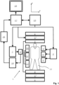
- Figure 2 illustrates a Cartesian k-space sampling scheme according to an embodiment of the invention.
- the so-called turbo spin echo (TSE) sequence is a well-known multi-echo imaging sequence.
- One 'shot' of the TSE sequence comprises an initial RF pulse for excitation of magnetic resonance followed by a plurality of rapidly applied (typically 180°) refocusing RF pulses generating a train of differently phase-encoded spin echo signals.
- the echo signals are acquired, wherein each echo signal represents a k-space profile, i.e. a one-dimensional sample of k-space, the position of the k-space profile in k-space being determined by the applied frequency encoding and phase encoding switched magnetic field gradients of the sequence.
- the so-called turbo factor is the number of echoes acquired after each excitation.
- a plurality of shots of the multi-echo sequence is applied for completely sampling k-space in order to be able to reconstruct a MR image from the acquired k-space profiles.
- TSE sequences are applied today in almost all applications. Despite its wide use it is known to be very sensitive to motion due to the segmented k-space distributed acquisition. Small movements of the imaged object can introduce ghosts overlapping with the anatomy of interest disturbing the overall diagnostic value of a scan.
- the k-space profiles acquired during one shot of the TSE sequence constitute one subset of a number of temporally successively acquired subsets.
- three shots of a TSE sequence with turbo factor 5 are applied to sample k-space.
- the horizontal lines in the diagram of Figure 2 represent the echo signals generated by the TSE sequence.
- the k-space profiles designated by S11-S15 are acquired during the first shot and constitute the first subset.
- the k-space profiles designated by S21-S25 are acquired during the second shot and constitute the second subset, while the k-space profiles designated by S31-S35 are acquired during the third shot and constitute the third subset.
- Each subset comprises five k-space profiles which sample k-space with sub-sampling.
- the three subsets complement each other to form a fully sampled set of k-space profiles.
- the difference ⁇ k between the k-space profiles of the different subsets determines the size of the FOV in the phase-encoding direction ky.
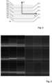
- a single-subset MR image is reconstructed from each subset. This is illustrated in Figure 3 .
- the left nine MR images shown in Figure 3 are the single-subset MR images reconstructed from the echo signals acquired as illustrated in Figure 2 using a TSE sequence with nine shots and a turbo factor of 33 (head scan).
- the contrast in the nine single-subset MR images differs significantly as the subsets cover different locations in k-space.
- a gradient MR image is reconstructed from each single-subset MR image.
- the right nine MR images in Figure 3 are the corresponding gradient MR images derived from the single-subset MR images shown in the left part of Figure 3 by computing the voxel-vise spatial derivatives of the image values in the phase-encoding direction ky. As can be seen, the contents of the nine gradient MR images show a much higher degree of similarity than the single-subset MR images.
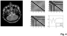
- Figure 4 illustrates the motion detection scheme of the invention. Motion is detected by comparing the gradient MR images with each other. This is performed by computing the pairwise cross-correlations of the gradient MR images.
- MR signals are acquired using a TSE sequence with ten shots and a turbo factor of 30.
- the top middle diagram shows the correlation matrix for the case of no motion corruption.
- the matrix has ten lines and ten columns corresponding to the number of shots of the TSE sequence, i.e. the number of subsets within the meaning of the invention.
- Each field of the matrix comprises the value of the cross-correlation of the pair of gradient MR images computed from the respective single-subset MR images.
- shots 2 and 4 are motion-corrupted by introducing a shift by one voxel.
- the top right diagram shows the correlation matrix for a shift in the x-direction
- the bottom middle diagram shows the correlation matrix for a shift in the y-direction.
- a significant drop of the cross-correlation is observed in columns 2 and 4 and lines 2 and 4 of the respective correlation matrix.
- the bottom right diagram shows the summation of the cross-correlations over the columns for each line of the respective matrix.
- the diagram clearly reflects the drop of the cross-correlations in lines 2 and 4 for both shift directions. This summation can be used according to the invention as a motion detection-measure.
- Low values indicate a low correlation of the respective gradient MR-image with the other gradient MR images and, thus, an increased probability of motion corruption.
- This may be used, for example, to reconstruct a motion-compensated MR image from the fully samples set of k-space profiles formed from the entirety of the subsets, wherein the subsets are weighted according to the motion detection-measure.
- re-acquisition could be initiated automatically for those subsets for which the motion detection-metric is below a given threshold.
- a correspondingly reconstructed MR image (head image) is shown on the left in Figure 4 .
- the concept of the invention can be extended to 3D or higher-dimensional imaging in a straight forward fashion, for example using subsets comprising k-space profiles that are phase-encoded in the ky and kz directions and evenly spread out over three-dimensional k-space.
- Each subset then comprises a number of equidistant, parallel k-space profiles (extending along the frequency-encoding direction kx).
- One subset differs from another subset in terms of the k-space locations of the individual k-space profiles, with constant offsets ⁇ ky and ⁇ kz between the measured k-space profiles of the different subsets in the two phase-encoding directions ky and kz.
Landscapes
- Physics & Mathematics (AREA)
- General Physics & Mathematics (AREA)
- High Energy & Nuclear Physics (AREA)
- Condensed Matter Physics & Semiconductors (AREA)
- Engineering & Computer Science (AREA)
- Nuclear Medicine, Radiotherapy & Molecular Imaging (AREA)
- Radiology & Medical Imaging (AREA)
- Signal Processing (AREA)
- General Health & Medical Sciences (AREA)
- Health & Medical Sciences (AREA)
- Artificial Intelligence (AREA)
- Computer Vision & Pattern Recognition (AREA)
- Magnetic Resonance Imaging Apparatus (AREA)
Description
- The invention relates to the field of magnetic resonance (MR) imaging. It concerns a method of MR imaging of an object placed in the examination volume of a MR device. The invention also relates to a MR device and to a computer program to be run on a MR device.
- Image-forming MR methods which utilize the interaction between magnetic fields and nuclear spins in order to form two-dimensional or three-dimensional images are widely used nowadays, notably in the field of medical diagnostics, because for the imaging of soft tissue they are superior to other imaging methods in many respects, do not require ionizing radiation and are usually not invasive.
- According to the MR method in general, the body of the patient to be examined is arranged in a strong, uniform magnetic field B0 whose direction at the same time defines an axis (normally the z-axis) of the co-ordinate system to which the measurement is related. The magnetic field B0 produces different energy levels for the individual nuclear spins in dependence on the magnetic field strength which can be excited (spin resonance) by application of an electromagnetic alternating field (RF field) of defined frequency (so-called Larmor frequency, or MR frequency).
- From a macroscopic point of view, the distribution of the individual nuclear spins produces an overall magnetization which can be deflected out of the state of equilibrium by application of an electromagnetic pulse of appropriate frequency (RF pulse) while the corresponding magnetic field B1 of this RF pulse extends perpendicular to the z-axis, so that the magnetization performs a precessional motion about the z-axis. The precessional motion describes a surface of a cone whose angle of aperture is referred to as flip angle. The magnitude of the flip angle is dependent on the strength and the duration of the applied electromagnetic pulse. In the case of a so-called 90° pulse, the magnetization is deflected from the z axis to the transverse plane (flip angle 90°).
- The transverse magnetization and its variation can be detected by means of receiving RF coils which are arranged and oriented within an examination volume of the MR device in such a manner that the variation of the magnetization is measured in the direction perpendicular to the z-axis.
- In order to realize spatial resolution in the body, constant magnetic field gradients extending along the three main axes are superposed on the uniform magnetic field B0, leading to a linear spatial dependency of the spin resonance frequency. The signal picked up in the receiving coils then contains components of different frequencies which can be associated with different locations in the body.
- The signal data obtained via the receiving coils correspond to the spatial frequency domain and are called k-space data. The k-space data usually include multiple acquired k-space profiles (lines in k-space) of different phase encoding. Each k-space profile is digitized by collecting a number of samples. A set of k-space data is converted to an MR image by means of Fourier transformation.
- In a variety of MRI applications, motion of the examined patient can adversely affect image quality. Acquisition of sufficient MR signals for reconstruction of an image takes a finite period of time. Motion of the patient during that finite acquisition time typically results in motion artifacts in the reconstructed MR image. In conventional MR imaging approaches, the acquisition time can be reduced to a very small extent only, when a given resolution of the MR image is specified. In the case of medical MR imaging, motion artifacts can result for example from cardiac and respiratory cyclic motion, and other physiological processes, as well as from patient motion resulting in blurring, misregistration, deformation and ghosting artifacts.
- Different approaches have been developed to overcome problems with respect to motion in MR imaging. Among these is the so-called PROPELLER imaging technique. In the PROPELLER concept (Periodically Rotated Overlapping ParalEL Lines, see James G. Pipe: `Motion Correction With PROPELLER MRI: Application to Head Motion and Free-Breathing Cardiac Imaging', Magnetic Resonance in Medicine, vol. 42, 1999, pages 963-969), MR signal data are acquired in k-space in N strips, each consisting of L parallel k-space lines, corresponding to the L lowest frequency phase-encoding lines in a Cartesian-based k-space sampling scheme. Each strip, which is also referred to as k-space blade, is rotated in k-space by an angle of, for example, 180°/N, so that the total MR data set spans a circle in k-space. If a full k-space data matrix having a diameter M is desired, then L and N may be chosen so that L×N=M×π/2. One essential characteristic of PROPELLER is that a central circular portion in k-space, having a diameter L, is acquired for each k-space blade. This central portion can be used to reconstruct a low-resolution MR image for each k-space blade. The low-resolution MR images are compared to each other to detect in-plane displacements and phase errors, which are due to patient motion. A suitable technique such as cross-correlation is employed to determine which k-space blades were acquired with significant motion-induced displacement or include other types of artifacts. As the MR signal data are combined in k-space before the reconstruction of the final MR image, the MR data from k-space blades are weighted according to the artifact level detected by cross-correlating the k-space blades, so that artifacts are reduced in the final MR image. The PROPELLER technique makes use of oversampling in the central portion of k-space in order to obtain an MR image acquisition technique that is robust with respect to motion of the examined patient during MR signal acquisition.
- However, drawbacks of the known PROPELLER approach result from the fact that its application is restricted to the specific circular acquisition of k-space profiles from a number of successively rotated blades. The highly effective motion-compensation and motion-correction concept of the PROPELLER approach is not compatible with Cartesian k-space sampling schemes.
- As an alternative, the so-called navigator technique has been developed to overcome problems with respect to motion by prospectively adjusting the imaging parameters, which define the location and orientation of the volume of interest within the imaging volume. In the navigator technique hereby, a set of navigator signals is acquired from a spatially restricted volume that crosses, for example, the diaphragm of the examined patient to determine the breathing motion of the patient. For registering the navigator signals, so-called 2D RF pulses may be used. These excite the spatially restricted navigator volume, for example of pencil beam shape, which is read out using a gradient echo. Other ways to detect the motion-induced momentary position of the volume of interest is the acquisition of two-dimensional sagittal slices that are positioned at the top of the diaphragm, or the acquisition of three-dimensional low-resolution data sets. The respective navigator volume is interactively placed in such a way that a displacement value indicating the instantaneous position of the moving anatomy can be reconstructed from the acquired navigator signals and used for motion correction of the volume of interest in real time. The navigator technique is primarily used for minimizing the effects of breathing motion in body and cardiac exams where respiratory motion can severely deteriorate the image quality. Gating and image correction based on the MR navigator signals may be used to reduce these artifacts.
- However, a drawback of the navigator technique is that additional acquisition of the navigator signals is required which results in an extension of the overall scan time. Moreover, the known navigator methods are difficult to apply if the volume of interest, from which the MR signals for imaging are to be acquired, partially overlaps with the navigator volume. If the navigator volume is (at least partly) superimposed upon the respective volume of interest, the image quality may be degraded due to incorrect detection of the motion state or due to saturation of the nuclear magnetization within the navigator volume.
- The US patent
US 6 144 874 concerns an magnetic resonance imaging method in which central k-space vies and peripheral k-space views are acquired in a narrow and wider acquisition window, respectively. The k-space views are acquired upon first and second respiratory gating signals. Further MRI techniques involving motion detection are known fromUS 2010/0171497 A1 ,US 5,382,902 ,US 2012/0243756 A1 andUS 2015/0015691 A1 . - From the foregoing it is readily appreciated that there is a need for an improved MR imaging technique. It is consequently an object of the invention to provide a method that enables efficient motion-compensation and/or motion-correction and that is compatible with Cartesian sampling of k-space.
- In accordance with the invention, a method of MR imaging of an object placed in an examination volume of a MR device is provided as defined in
claim 1. The method comprises the steps of: - generating MR signals by subjecting the object to a MR imaging sequence of at least one RF pulse and switched magnetic field gradients;
- acquiring the MR signals as a plurality of temporally successive subsets, each subset comprising a number of k-space profiles with sub-sampling of k-space, wherein a k-space sampling density of each subset is below the Nyquist threshold with respect to a field-of-view to be imaged, wherein all subsets cover the same pre-determined region of k-space in that the k-space profiles of each subset are evenly spread out over k-space, wherein one subset differs from another subset only in terms of the k-space locations of the individual k-space profiles, with a constant offset between the measured k-space profiles of different subsets,
- reconstructing a single-subset MR image from each subset;
- computing a gradient MR image from each single-subset MR image,
- detecting motion by comparing the gradient MR images with each other.
- The gist of the invention is the application of the motion detection/correction approach of the above-described PROPELLER technique to other kinds of k-space sampling, particularly Cartesian k-space sampling. The invention enables a fast and robust motion detection without the need of additional acquisition of navigators.
- According to the invention, MR signals are acquired by any established imaging sequence, for example a spin echo sequence or a gradient echo sequence, as a plurality of subsets in temporal succession. Each subset comprises a number of k-space profiles, wherein the k-space profiles of each subset are acquired with sub-sampling. This means that the k-space sampling density of each subset is below the Nyquist threshold with respect to the field-of-view (FOV) to be imaged. The thus reduced number of phase encoding steps enables the acquisition of each subset within a short period of time. The duration of the acquisition of a single subset should be short in comparison to the typical timescale of the expected motion of the object such that each subset essentially reflects a certain motion state of the object. In a typical scenario of medical imaging of a human object, the acquisition of a single subset should preferably take less than, for example, 100 ms, comparable to the duration of the acquisition of a single k-space blade in PROPELLER imaging. The best performance of the method of the invention will be obtained using as large as possible subsets (in terms of the number of k-space profiles per subset) as long as the k-space data of each subset can be attributed to a single motion state. If the typical time scale of the relevant motion is known, the number of k-space profiles acquired per subset can be determined accordingly.
- A single-subset MR image is reconstructed from each subset according to the invention. The k-space data of the subsets complement each other to form a fully sampled set of k-space profiles. In other words, each subset covers other locations in k-space than the other subsets. The consequence is that the single-subset MR images have different contents and cannot directly be compared to each other (or cross-correlated) like in PROPELLER imaging for detecting motion.
- The essential feature of the invention is that a gradient MR image is computed from each single-subset MR image. Within the meaning of the invention, a gradient MR image is a MR image derived from the respective single-subset MR image, whereby the influence of the central region of k-space (the low spatial frequency information), which contains the contrast information, is reduced or even fully removed in the gradient MR image. According to the invention, each gradient MR image contains the spatial derivatives of the image values (in at least one spatial direction) of the corresponding single-subset MR image. It is an insight of the invention that there is significantly less difference between the gradient MR images than between the single-subset MR images. It turns out that the cross-correlation between the MR images containing spatial derivative content (the gradient MR images) is rather high and motion-dependent. If there is motion between the acquisition of two subsets, the cross-correlation of gradient MR images drops significantly. This is exploited by the invention. Motion is detected according to the invention by comparing the gradient MR images with each other. The comparison may be performed by computing the cross-correlation of each pair of gradient images. The cross-correlation is particularly well-suited as a scalar measure of similarity of the gradient MR images, like the cross-correlation of the single-blade images in PROPELLER imaging. The cross-correlation may be computed on the basis of the gradient MR images being magnitude images. However, the cross correlation may also be based on complex gradient MR images after performing a linear phase correction to compensate for the shift in position between the subsets in k-space.
- In a preferred embodiment of the invention, a motion-compensated MR image is reconstructed from the fully sampled set of k-space profiles, wherein the subsets are weighted according to the detected motion. The subsets are combined into the fully sampled set of k-space profiles by weighted superposition. The weighted superposition enables an effective and targeted reduction of motion-induced image artifacts in the reconstructed MR image. The weighting factors of the weighted superposition are derived from the comparison of the gradient MR images so that image artifacts are avoided by applying a reduced weighting to the motion-corrupted subsets.
- In an alternative embodiment, motion correction may be applied to at least one of the subsets according to the detected motion such that a motion-corrected MR image can be reconstructed from the fully sampled set of k-space profiles formed from the motion-corrected subsets. As in conventional PROPELLER imaging, the method of the invention may comprise the step of estimating and correcting motion-induced displacements and phase errors in the subsets. For example, displacements (translation and/or rotation) and phase errors, which are caused by patient motion, can be derived from the comparison of the gradient MR images. These factors may be corrected for in each subset in accordance with the invention prior to reconstructing the motion-corrected MR image. The invention thus provides a MR imaging method that is robust with respect to motion of the examined patient during MR signal acquisition.
- According to another alternative, one or more motion-corrupted subsets are re-acquired, such that a final MR image is reconstructed from the fully sampled set of k-space profiles formed from the not motion-corrupted subsets and the re-acquired subsets. Motion-corrupted subsets are identified by the comparison of the gradient MR images. The respective subsets are then re-acquired. Optionally, the FOV of the k-space sampling is adapted in the step of re-acquiring the subsets according to the detected motion. In this way, the FOV may follow the detected motion of the imaged object.
- According to the invention, all subsets acquired according to the invention cover the same pre-determined region of k-space corresponding to the respective imaging task. The subsets may be acquired using Cartesian sampling of k-space, wherein each subset comprises a number of equidistant, parallel k-space profiles. In other words, the k-space profiles of each subset are evenly spread out over k-space, wherein one subset differs from another subset only in terms of the k-space locations of the individual k-space profiles, with a constant offset between the measured k-space profiles of different subsets. This is the typical k-space acquisition scheme of a multi-echo imaging sequence (for example a 'turbo' spin echo - TSE sequence) , wherein each subset corresponds to a train of MR echo signals generated in a single 'shot' (i.e. after a single RF excitation) of the multi-echo imaging sequence. However, the imaging sequence used in accordance with the invention may be any conventional spin echo or gradient echo sequence with suitable ordering of the acquisition of the k-space profiles.
- Alternatively, the subsets may be acquired using non-Cartesian sampling patterns, such as multi-shot spiral scanning (with interleaved spiral k-space trajectories) or radial scanning. Basically, the k-space sampling patterns/trajectories of the subsets to be compared should have the same geometry which is either translated in k-space (like in the above-described case of Cartesian sampling) or rotated (for spiral/radial scanning).
- In yet another preferred embodiment of the invention, the subsets may comprise three-dimensional or higher-dimensional k-space data. The method of the invention is equally well-suited for two-dimensional and three-dimensional MR imaging as well as higher-dimensional MR imaging, such as dynamic MR imaging or spectroscopic MR imaging, for example.
- The method of the invention described thus far can be carried out by means of a MR device as defined in
claim 11 including at least one main magnet coil for generating a uniform, steady magnetic field B0 within an examination volume, a number of gradient coils for generating switched magnetic field gradients in different spatial directions within the examination volume, at least one RF coil for generating RF pulses within the examination volume and/or for receiving MR signals from an object positioned in the examination volume, a control unit for controlling the temporal succession of RF pulses and switched magnetic field gradients, and a reconstruction unit for reconstructing MR images from the received MR signals. The method of the invention can be implemented by a corresponding programming of the reconstruction unit and/or the control unit of the MR device. - The method of the invention can be advantageously carried out on most MR devices in clinical use at present. To this end it is merely necessary to utilize a computer program by which the MR device is controlled such that it performs the above-explained method steps of the invention. The computer program may be present either on a data carrier or be present in a data network so as to be downloaded for installation in the control unit of the MR device.
- The enclosed drawings disclose preferred embodiments of the present invention. It should be understood, however, that the drawings are designed for the purpose of illustration only and not as a definition of the limits of the invention. In the drawings:
-
Figure 1 shows a MR device for carrying out the method of the invention; -
Figure 2 schematically illustrates a Cartesian acquisition of k-space profiles according to the invention; -
Figure 3 shows single-subset MR images and corresponding gradient MR images used for motion-detection according to the invention; -
Figure 4 illustrates the motion-detection approach of the invention in combination with TSE scanning. - With reference to
Figure 1 , aMR device 1 is shown. The device comprises superconducting or resistive main magnet coils 2 such that a substantially uniform, temporally constant main magnetic field B0 is created along a z-axis through an examination volume. The device further comprises a set of (1st, 2nd, and - where applicable - 3rd order) shimming coils 2', wherein the current flow through the individual shimming coils of the set 2' is controllable for the purpose of minimizing B0 deviations within the examination volume. - A magnetic resonance generation and manipulation system applies a series of RF pulses and switched magnetic field gradients to invert or excite nuclear magnetic spins, induce magnetic resonance, refocus magnetic resonance, manipulate magnetic resonance, spatially and otherwise encode the magnetic resonance, saturate spins, and the like to perform MR imaging.
- More specifically, a
gradient amplifier 3 applies current pulses or waveforms to selected ones of whole-body gradient coils 4, 5 and 6 along x, y and z-axes of the examination volume. A digital RF frequency transmitter 7 transmits RF pulses or pulse packets, via a send/receiveswitch 8, to abody RF coil 9 to transmit RF pulses into the examination volume. A typical MR imaging sequence is composed of a packet of RF pulse segments of short duration which, together with any applied magnetic field gradients, achieve a selected manipulation of nuclear magnetic resonance signals. The RF pulses are used to saturate, excite resonance, invert magnetization, refocus resonance, or manipulate resonance and select a portion of abody 10 positioned in the examination volume. The MR signals are also picked up by thebody RF coil 9. - For generation of MR images of limited regions of the
body 10 or for scan acceleration by means of parallel imaging, a set of local array RF coils 11, 12, 13 are placed contiguous to the region selected for imaging. The array coils 11, 12, 13 can be used to receive MR signals induced by body-coil RF transmissions. - The resultant MR signals are picked up by the
body RF coil 9 and/or by the array RF coils 11, 12, 13 and demodulated by areceiver 14 preferably including a preamplifier (not shown). Thereceiver 14 is connected to the RF coils 9, 11, 12 and 13 via send/receiveswitch 8. - A
host computer 15 controls the shimming coils 2' as well as thegradient pulse amplifier 3 and the transmitter 7 to generate any of a plurality of MR imaging sequences, such as echo planar imaging (EPI), echo volume imaging, gradient and spin echo imaging, fast spin echo imaging, and the like. For the selected sequence, thereceiver 14 receives a single or a plurality of MR data lines in rapid succession following each RF excitation pulse. Adata acquisition system 16 performs analog-to-digital conversion of the received signals and converts each MR data line to a digital format suitable for further processing. In modern MR devices thedata acquisition system 16 is a separate computer which is specialized in acquisition of raw image data. - Ultimately, the digital raw image data are reconstructed into an image representation by a
reconstruction processor 17 which applies a Fourier transform or other appropriate reconstruction algorithms, such as SENSE or GRAPPA. The MR image may represent a planar slice through the patient, an array of parallel planar slices, a three-dimensional volume, or the like. The image is then stored in an image memory where it may be accessed for converting slices, projections, or other portions of the image representation into appropriate format for visualization, for example via avideo monitor 18 which provides a man-readable display of the resultant MR image. -
Figure 2 illustrates a Cartesian k-space sampling scheme according to an embodiment of the invention. - The so-called turbo spin echo (TSE) sequence is a well-known multi-echo imaging sequence. One 'shot' of the TSE sequence comprises an initial RF pulse for excitation of magnetic resonance followed by a plurality of rapidly applied (typically 180°) refocusing RF pulses generating a train of differently phase-encoded spin echo signals. The echo signals are acquired, wherein each echo signal represents a k-space profile, i.e. a one-dimensional sample of k-space, the position of the k-space profile in k-space being determined by the applied frequency encoding and phase encoding switched magnetic field gradients of the sequence. The so-called turbo factor is the number of echoes acquired after each excitation. Typically, a plurality of shots of the multi-echo sequence is applied for completely sampling k-space in order to be able to reconstruct a MR image from the acquired k-space profiles. TSE sequences are applied today in almost all applications. Despite its wide use it is known to be very sensitive to motion due to the segmented k-space distributed acquisition. Small movements of the imaged object can introduce ghosts overlapping with the anatomy of interest disturbing the overall diagnostic value of a scan.
- According to the invention, the k-space profiles acquired during one shot of the TSE sequence constitute one subset of a number of temporally successively acquired subsets. In the embodiment shown in
Figure 2 , three shots of a TSE sequence withturbo factor 5 are applied to sample k-space. The horizontal lines in the diagram ofFigure 2 represent the echo signals generated by the TSE sequence. The k-space profiles designated by S11-S15 are acquired during the first shot and constitute the first subset. The k-space profiles designated by S21-S25 are acquired during the second shot and constitute the second subset, while the k-space profiles designated by S31-S35 are acquired during the third shot and constitute the third subset. Each subset comprises five k-space profiles which sample k-space with sub-sampling. The three subsets complement each other to form a fully sampled set of k-space profiles. The difference Δk between the k-space profiles of the different subsets determines the size of the FOV in the phase-encoding direction ky. - According to the invention, a single-subset MR image is reconstructed from each subset. This is illustrated in
Figure 3 . The left nine MR images shown inFigure 3 are the single-subset MR images reconstructed from the echo signals acquired as illustrated inFigure 2 using a TSE sequence with nine shots and a turbo factor of 33 (head scan). As can be seen, the contrast in the nine single-subset MR images differs significantly as the subsets cover different locations in k-space. According to the invention, a gradient MR image is reconstructed from each single-subset MR image. The right nine MR images inFigure 3 are the corresponding gradient MR images derived from the single-subset MR images shown in the left part ofFigure 3 by computing the voxel-vise spatial derivatives of the image values in the phase-encoding direction ky. As can be seen, the contents of the nine gradient MR images show a much higher degree of similarity than the single-subset MR images. -
Figure 4 illustrates the motion detection scheme of the invention. Motion is detected by comparing the gradient MR images with each other. This is performed by computing the pairwise cross-correlations of the gradient MR images. In the embodiment shown inFigure 4 , MR signals are acquired using a TSE sequence with ten shots and a turbo factor of 30. The top middle diagram shows the correlation matrix for the case of no motion corruption. The matrix has ten lines and ten columns corresponding to the number of shots of the TSE sequence, i.e. the number of subsets within the meaning of the invention. Each field of the matrix comprises the value of the cross-correlation of the pair of gradient MR images computed from the respective single-subset MR images. In order to demonstrate the principle of the invention,shots columns lines lines Figure 4 . - While the invention has been described above with reference to a TSE imaging sequence, it has to be noted that other known imaging sequences (such as TFE, FFE or SE) can be used as well with a corresponding ordering of the acquired k-space profiles.
- The concept of the invention can be extended to 3D or higher-dimensional imaging in a straight forward fashion, for example using subsets comprising k-space profiles that are phase-encoded in the ky and kz directions and evenly spread out over three-dimensional k-space. Each subset then comprises a number of equidistant, parallel k-space profiles (extending along the frequency-encoding direction kx). One subset differs from another subset in terms of the k-space locations of the individual k-space profiles, with constant offsets Δky and Δkz between the measured k-space profiles of the different subsets in the two phase-encoding directions ky and kz.
Claims (12)
- Method of MR imaging of an object (10) placed in an examination volume of a MR device (1), the method comprising the steps of:- generating MR signals by subjecting the object (10) to a MR imaging sequence of at least one RF pulse and switched magnetic field gradients;- acquiring the MR signals as a plurality of temporally successive subsets, each subset comprising a number of k-space profiles with sub-sampling of k-space, wherein a k-space sampling density of each subset is below the Nyquist threshold with respect to a field-of view to be imaged, wherein all subsets cover the same pre-determined region of k-space in that the k-space profiles of each subset are evenly spread out over k-space, wherein one subset differs from another subset only in terms of the k-space locations of the individual k-space profiles, with a constant offset between the measured k-space profiles of different subsets, and wherein the subsets complement each other to form a fully sampled set of k-space profiles;- reconstructing a single-subset MR image from each subset;- computing a gradient MR image from each single-subset MR image, wherein each gradient image is computed by determining spatial derivatives of the image values of the respective single-subset MR image along at least one spatial direction so as to reduce the influence of the central region of k-space; and- detecting motion by comparing the gradient MR images with each other.
- Method of claim 1, further comprising:- reconstructing a motion-compensated MR image from the fully sampled set of k-space profiles, wherein the subsets are weighted according to the detected motion.
- Method of claim 1, further comprising:- applying motion correction to at least one of the subsets according to the detected motion; and- reconstructing a motion-corrected MR image from the fully sampled set of k-space profiles formed from the motion-corrected subsets.
- Method of claim 1, further comprising:- re-acquiring one or more motion-corrupted subsets; and- reconstructing a final MR image from the fully sampled set of k-space profiles formed from the not motion-corrupted subsets and the re-acquired subsets.
- Method of any one of claims 1-4, wherein the step of detecting motion includes computing the cross-correlation for each pair of gradient images.
- Method of any one of claims 1-5, wherein translation and/or rotation parameters of the detected motion are derived by comparing the gradient images with each other.
- Method of any one of claims 1-6, wherein the subsets are acquired using Cartesian sampling of k-space and each subset comprises a number of equidistant, parallel k-space profiles.
- Method of any one of claims 1-6, wherein the subsets are acquired using non-Cartesian sampling of k-space.
- Method of any one of claims 1-8, wherein the imaging sequence is a multi-echo imaging sequence comprising a number of shots, wherein each subset corresponds to a train of MR echo signals generated in a single shot of the multi-echo imaging sequence.
- Method of any one of claims 1-9, wherein the subsets comprise three-dimensional or higher-dimensional k-space data.
- MR device including at least one main magnet coil (2) for generating a uniform, steady magnetic field B0 within an examination volume, a number of gradient coils (4, 5, 6) for generating switched magnetic field gradients in different spatial directions within the examination volume, at least one RF coil (9) for generating RF pulses within the examination volume and/or for receiving MR signals from an object (10) positioned in the examination volume, a control unit (15) for controlling the temporal succession of RF pulses and switched magnetic field gradients, and a reconstruction unit (17) for reconstructing MR images from the received MR signals, wherein the MR device (1) is configured to perform the method of claim 1.
- Computer program to be run on a MR device, which computer program comprises instructions which, when executed by a control unit of the MR device, cause the MR device to perform the method of claim 1.
Applications Claiming Priority (2)
| Application Number | Priority Date | Filing Date | Title |
|---|---|---|---|
| EP15176760 | 2015-07-15 | ||
| PCT/EP2016/066687 WO2017009391A1 (en) | 2015-07-15 | 2016-07-13 | Mr imaging with motion detection |
Publications (2)
| Publication Number | Publication Date |
|---|---|
| EP3322997A1 EP3322997A1 (en) | 2018-05-23 |
| EP3322997B1 true EP3322997B1 (en) | 2024-09-11 |
Family
ID=53793991
Family Applications (1)
| Application Number | Title | Priority Date | Filing Date |
|---|---|---|---|
| EP16738440.3A Active EP3322997B1 (en) | 2015-07-15 | 2016-07-13 | Mr imaging with motion detection |
Country Status (5)
| Country | Link |
|---|---|
| US (1) | US10634753B2 (en) |
| EP (1) | EP3322997B1 (en) |
| JP (1) | JP6998218B2 (en) |
| CN (1) | CN107850652B (en) |
| WO (1) | WO2017009391A1 (en) |
Families Citing this family (22)
| Publication number | Priority date | Publication date | Assignee | Title |
|---|---|---|---|---|
| EP3470869A1 (en) * | 2017-10-10 | 2019-04-17 | Koninklijke Philips N.V. | Mr imaging using motion-dependent radial or spiral k-space sampling |
| CN108090937B (en) * | 2018-02-09 | 2021-03-19 | 奥泰医疗系统有限责任公司 | Self-adaptive correction method for magnetic resonance diffusion weighted imaging |
| CN108577841B (en) * | 2018-02-23 | 2021-09-10 | 奥泰医疗系统有限责任公司 | Weight calculation method for inhibiting non-rigid motion in PROPELLER technology |
| US11622742B2 (en) * | 2018-04-05 | 2023-04-11 | Siemens Medical Solutions Usa, Inc. | Motion signal derived from imaging data |
| EP3633401A1 (en) * | 2018-10-04 | 2020-04-08 | Siemens Healthcare GmbH | Prevention of compensating a wrongly detected motion in mri |
| EP3730962A1 (en) * | 2019-04-23 | 2020-10-28 | Koninklijke Philips N.V. | Parallel mr imaging using wave-encoding |
| US12002203B2 (en) | 2019-03-12 | 2024-06-04 | Bayer Healthcare Llc | Systems and methods for assessing a likelihood of CTEPH and identifying characteristics indicative thereof |
| US11948311B2 (en) | 2019-03-27 | 2024-04-02 | The General Hospital Corporation | Retrospective motion correction using a combined neural network and model-based image reconstruction of magnetic resonance data |
| US10806370B1 (en) * | 2019-04-25 | 2020-10-20 | General Electric Company | MRI system and method for detection and correction of patient motion |
| EP3748385A1 (en) * | 2019-06-04 | 2020-12-09 | Koninklijke Philips N.V. | Optimized k-space profile ordering for 3d radial or spiral mr imaging |
| EP3748384A1 (en) * | 2019-06-04 | 2020-12-09 | Koninklijke Philips N.V. | Spiral mr imaging with off-resonance artefact correction |
| CN117582208A (en) | 2019-09-18 | 2024-02-23 | 拜耳公司 | Method, system and computer readable medium for determining characteristics of tissue voxels |
| WO2021052850A1 (en) | 2019-09-18 | 2021-03-25 | Bayer Aktiengesellschaft | Generation of mri images of the liver |
| JP7542060B2 (en) | 2019-09-18 | 2024-08-29 | バイエル、アクチエンゲゼルシャフト | Predicting MRI images using a predictive model trained by supervised learning |
| EP3804615A1 (en) | 2019-10-08 | 2021-04-14 | Bayer AG | Generation of mri images of the liver |
| CA3156921A1 (en) | 2019-10-08 | 2021-04-15 | Bayer Aktiengesellschaft | Generation of mri images of the liver without contrast enhancement |
| EP4041057A1 (en) | 2019-10-11 | 2022-08-17 | Bayer Aktiengesellschaft | Acceleration of mri examinations |
| JP2023521640A (en) | 2020-04-03 | 2023-05-25 | バイエル、アクチエンゲゼルシャフト | Generation of radiological images |
| EP3913387A1 (en) | 2020-05-19 | 2021-11-24 | Koninklijke Philips N.V. | Motion estimation and correction in magnetic resonance imaging |
| US11519992B2 (en) | 2020-08-26 | 2022-12-06 | GE Precision Healthcare LLC | Systems and methods of automatically detecting and scoring motion artifacts in magnetic resonance imaging |
| US11275142B1 (en) * | 2020-11-05 | 2022-03-15 | GE Precision Healthcare LLC | System and method for performing motion-insensitive and quiet three-dimensional magnetic resonance imaging |
| DE102021203269A1 (en) * | 2021-03-31 | 2022-10-06 | Siemens Healthcare Gmbh | Method for reducing artefacts in image datasets recorded by means of magnetic resonance |
Family Cites Families (29)
| Publication number | Priority date | Publication date | Assignee | Title |
|---|---|---|---|---|
| JPH05154130A (en) * | 1991-12-06 | 1993-06-22 | Hitachi Ltd | Body motion artifact eliminating method |
| US5612619A (en) * | 1995-07-31 | 1997-03-18 | Feinberg David A | Grase-type three-dimensional MR pulse sequences |
| US5697370A (en) * | 1996-01-17 | 1997-12-16 | General Electric Company | Method for increasing temporal resolution of MR fluoroscopy |
| US6144874A (en) * | 1998-10-15 | 2000-11-07 | General Electric Company | Respiratory gating method for MR imaging |
| US6434413B1 (en) * | 1999-11-24 | 2002-08-13 | Koninklijke Philips Electronics, N.V. | Shifting sampling window and interleaves sparse K-space data acquisition for improved temporal resolution |
| US6717406B2 (en) * | 2000-03-14 | 2004-04-06 | Beth Israel Deaconess Medical Center, Inc. | Parallel magnetic resonance imaging techniques using radiofrequency coil arrays |
| GB2374672A (en) * | 2001-04-20 | 2002-10-23 | Marconi Medical Systems Uk Ltd | Magnetic Resonance Imaging |
| US6711190B2 (en) * | 2001-06-29 | 2004-03-23 | Koninklijke Philips Electronics N.V. | Laser transmitter bias circuit |
| US6617850B2 (en) | 2001-12-03 | 2003-09-09 | Mayo Foundation For Medical Education And Research | Motion correction of magnetic resonance images using phase difference of two orthogonal acquisitions |
| JP5123191B2 (en) * | 2005-09-22 | 2013-01-16 | ウイスコンシン アラムナイ リサーチ ファウンデーシヨン | Diffusion tensor imaging using highly constrained image reconstruction methods |
| EP1963830A4 (en) * | 2005-12-21 | 2013-04-24 | Yeda Res & Dev | Method and apparatus for acquiring high resolution spectral data or high definition images in inhomogeneous environments |
| US8406849B2 (en) | 2006-03-31 | 2013-03-26 | University Of Utah Research Foundation | Systems and methods for magnetic resonance imaging |
| DE102006033862B3 (en) | 2006-07-21 | 2007-12-06 | Siemens Ag | Image series recording and producing method for use in cine imaging of e.g. heart, involves reconstructing frames by reconstructing portion of complete sub-data sets, which are assigned to frames |
| US8155417B2 (en) | 2007-03-27 | 2012-04-10 | Hologic, Inc. | Post-acquisition adaptive reconstruction of MRI data |
| EP2806284B1 (en) * | 2007-04-27 | 2019-03-27 | Koninklijke Philips N.V. | Magnetic resonance device and method for propeller mri |
| US7602184B2 (en) * | 2007-04-30 | 2009-10-13 | The Regents Of The University Of California | Magnetic resonance spectroscopic imaging with short echo times |
| WO2008135885A1 (en) * | 2007-05-03 | 2008-11-13 | Koninklijke Philips Electronics N.V. | Propeller mri with phase correction |
| CN101470179B (en) | 2007-12-29 | 2012-06-27 | 西门子(中国)有限公司 | Method and apparatus for distortion calibration in magnetic resonance imaging |
| JP5305925B2 (en) * | 2009-01-05 | 2013-10-02 | ジーイー・メディカル・システムズ・グローバル・テクノロジー・カンパニー・エルエルシー | Magnetic resonance imaging system |
| RU2580189C2 (en) * | 2009-04-28 | 2016-04-10 | Конинклейке Филипс Электроникс Н.В. | Motion-compensated interventional magnetic resonance imaging |
| JP5388749B2 (en) | 2009-08-11 | 2014-01-15 | 株式会社東芝 | Magnetic resonance imaging system |
| CN101995561B (en) | 2010-10-22 | 2012-11-07 | 南方医科大学 | Reconstruction method of periodically rotated overlapping parallel lines with enhanced reconstruction (PROPELLER) magnetic resonance data based on image domain overlapping |
| US8306299B2 (en) | 2011-03-25 | 2012-11-06 | Wisconsin Alumni Research Foundation | Method for reconstructing motion-compensated magnetic resonance images from non-Cartesian k-space data |
| EP2626718A1 (en) * | 2012-02-09 | 2013-08-14 | Koninklijke Philips Electronics N.V. | MRI with motion correction using navigators acquired using a Dixon technique |
| CN103584864B (en) | 2012-08-15 | 2017-11-17 | 深圳迈瑞生物医疗电子股份有限公司 | A kind of MR imaging method and device |
| KR101437945B1 (en) | 2012-10-17 | 2014-09-11 | 주식회사 모코플렉스 | Dialog box management system, user terminal, dialog box exposure method and method for configurating dialog box exposure using the same |
| JP5977158B2 (en) | 2012-11-30 | 2016-08-24 | ジーイー・メディカル・システムズ・グローバル・テクノロジー・カンパニー・エルエルシー | Detection apparatus, magnetic resonance apparatus, detection method, and program |
| DE102013205832B4 (en) * | 2013-04-03 | 2025-04-30 | Siemens Healthineers Ag | Method and image data generation device for generating image data of a moving object, magnetic resonance system and computer program product |
| CN106030329B (en) | 2013-12-12 | 2019-09-27 | 皇家飞利浦有限公司 | MR Imaging Method Using Multiecho Segmented K-Space Acquisition |
-
2016
- 2016-07-13 JP JP2017566771A patent/JP6998218B2/en active Active
- 2016-07-13 EP EP16738440.3A patent/EP3322997B1/en active Active
- 2016-07-13 CN CN201680041442.8A patent/CN107850652B/en active Active
- 2016-07-13 US US15/742,902 patent/US10634753B2/en active Active
- 2016-07-13 WO PCT/EP2016/066687 patent/WO2017009391A1/en active Application Filing
Also Published As
| Publication number | Publication date |
|---|---|
| CN107850652A (en) | 2018-03-27 |
| CN107850652B (en) | 2021-10-15 |
| US10634753B2 (en) | 2020-04-28 |
| WO2017009391A1 (en) | 2017-01-19 |
| JP6998218B2 (en) | 2022-01-18 |
| JP2018519909A (en) | 2018-07-26 |
| US20180210058A1 (en) | 2018-07-26 |
| EP3322997A1 (en) | 2018-05-23 |
Similar Documents
| Publication | Publication Date | Title |
|---|---|---|
| EP3322997B1 (en) | Mr imaging with motion detection | |
| US10444315B2 (en) | MRI with motion correction using navigators acquired using a dixon technique | |
| JP5980126B2 (en) | Simultaneous multi-slice magnetic resonance imaging using single and multi-channel receive coils | |
| EP3635425B1 (en) | Mr imaging using a stack-of-stars acquisition with variable contrast | |
| EP2496954B1 (en) | Mr imaging using navigators | |
| CN106796274B (en) | PROPELLER-MR imaging with artifact suppression | |
| JP2020522344A (en) | Parallel multi-slice MR imaging | |
| US20210109181A1 (en) | Mr imaging using a stack-of-stars acquisition with intrinsic motion correction | |
| WO2018114554A1 (en) | Dixon-type water/fat separation mr imaging | |
| US10996305B2 (en) | Propeller MR imaging with relaxation weightings varying between k-space blades and k-space data lines | |
| EP3185029A1 (en) | Mr imaging using propeller acquisition with t2 decay correction | |
| WO2017108543A1 (en) | Dti with correction of motion-induced diffusion gradient inconsistency | |
| EP3118643A1 (en) | Dynamic propeller mr imaging |
Legal Events
| Date | Code | Title | Description |
|---|---|---|---|
| STAA | Information on the status of an ep patent application or granted ep patent |
Free format text: STATUS: UNKNOWN |
|
| STAA | Information on the status of an ep patent application or granted ep patent |
Free format text: STATUS: THE INTERNATIONAL PUBLICATION HAS BEEN MADE |
|
| PUAI | Public reference made under article 153(3) epc to a published international application that has entered the european phase |
Free format text: ORIGINAL CODE: 0009012 |
|
| STAA | Information on the status of an ep patent application or granted ep patent |
Free format text: STATUS: REQUEST FOR EXAMINATION WAS MADE |
|
| 17P | Request for examination filed |
Effective date: 20180215 |
|
| AK | Designated contracting states |
Kind code of ref document: A1 Designated state(s): AL AT BE BG CH CY CZ DE DK EE ES FI FR GB GR HR HU IE IS IT LI LT LU LV MC MK MT NL NO PL PT RO RS SE SI SK SM TR |
|
| AX | Request for extension of the european patent |
Extension state: BA ME |
|
| DAV | Request for validation of the european patent (deleted) | ||
| DAX | Request for extension of the european patent (deleted) | ||
| RAP1 | Party data changed (applicant data changed or rights of an application transferred) |
Owner name: KONINKLIJKE PHILIPS N.V. |
|
| STAA | Information on the status of an ep patent application or granted ep patent |
Free format text: STATUS: EXAMINATION IS IN PROGRESS |
|
| 17Q | First examination report despatched |
Effective date: 20210510 |
|
| STAA | Information on the status of an ep patent application or granted ep patent |
Free format text: STATUS: EXAMINATION IS IN PROGRESS |
|
| GRAP | Despatch of communication of intention to grant a patent |
Free format text: ORIGINAL CODE: EPIDOSNIGR1 |
|
| STAA | Information on the status of an ep patent application or granted ep patent |
Free format text: STATUS: GRANT OF PATENT IS INTENDED |
|
| INTG | Intention to grant announced |
Effective date: 20240410 |
|
| GRAS | Grant fee paid |
Free format text: ORIGINAL CODE: EPIDOSNIGR3 |
|
| GRAA | (expected) grant |
Free format text: ORIGINAL CODE: 0009210 |
|
| STAA | Information on the status of an ep patent application or granted ep patent |
Free format text: STATUS: THE PATENT HAS BEEN GRANTED |
|
| AK | Designated contracting states |
Kind code of ref document: B1 Designated state(s): AL AT BE BG CH CY CZ DE DK EE ES FI FR GB GR HR HU IE IS IT LI LT LU LV MC MK MT NL NO PL PT RO RS SE SI SK SM TR |
|
| REG | Reference to a national code |
Ref country code: GB Ref legal event code: FG4D |
|
| REG | Reference to a national code |
Ref country code: CH Ref legal event code: EP |
|
| REG | Reference to a national code |
Ref country code: DE Ref legal event code: R096 Ref document number: 602016089352 Country of ref document: DE |
|
| REG | Reference to a national code |
Ref country code: IE Ref legal event code: FG4D |
|
| REG | Reference to a national code |
Ref country code: DE Ref legal event code: R084 Ref document number: 602016089352 Country of ref document: DE |
|
| REG | Reference to a national code |
Ref country code: LT Ref legal event code: MG9D |
|
| PG25 | Lapsed in a contracting state [announced via postgrant information from national office to epo] |
Ref country code: NO Free format text: LAPSE BECAUSE OF FAILURE TO SUBMIT A TRANSLATION OF THE DESCRIPTION OR TO PAY THE FEE WITHIN THE PRESCRIBED TIME-LIMIT Effective date: 20241211 |
|
| REG | Reference to a national code |
Ref country code: NL Ref legal event code: MP Effective date: 20240911 |
|
| PG25 | Lapsed in a contracting state [announced via postgrant information from national office to epo] |
Ref country code: GR Free format text: LAPSE BECAUSE OF FAILURE TO SUBMIT A TRANSLATION OF THE DESCRIPTION OR TO PAY THE FEE WITHIN THE PRESCRIBED TIME-LIMIT Effective date: 20241212 Ref country code: FI Free format text: LAPSE BECAUSE OF FAILURE TO SUBMIT A TRANSLATION OF THE DESCRIPTION OR TO PAY THE FEE WITHIN THE PRESCRIBED TIME-LIMIT Effective date: 20240911 |
|
| PG25 | Lapsed in a contracting state [announced via postgrant information from national office to epo] |
Ref country code: BG Free format text: LAPSE BECAUSE OF FAILURE TO SUBMIT A TRANSLATION OF THE DESCRIPTION OR TO PAY THE FEE WITHIN THE PRESCRIBED TIME-LIMIT Effective date: 20240911 |
|
| PG25 | Lapsed in a contracting state [announced via postgrant information from national office to epo] |
Ref country code: LV Free format text: LAPSE BECAUSE OF FAILURE TO SUBMIT A TRANSLATION OF THE DESCRIPTION OR TO PAY THE FEE WITHIN THE PRESCRIBED TIME-LIMIT Effective date: 20240911 |
|
| PG25 | Lapsed in a contracting state [announced via postgrant information from national office to epo] |
Ref country code: HR Free format text: LAPSE BECAUSE OF FAILURE TO SUBMIT A TRANSLATION OF THE DESCRIPTION OR TO PAY THE FEE WITHIN THE PRESCRIBED TIME-LIMIT Effective date: 20240911 |
|
| PG25 | Lapsed in a contracting state [announced via postgrant information from national office to epo] |
Ref country code: RS Free format text: LAPSE BECAUSE OF FAILURE TO SUBMIT A TRANSLATION OF THE DESCRIPTION OR TO PAY THE FEE WITHIN THE PRESCRIBED TIME-LIMIT Effective date: 20241211 Ref country code: ES Free format text: LAPSE BECAUSE OF FAILURE TO SUBMIT A TRANSLATION OF THE DESCRIPTION OR TO PAY THE FEE WITHIN THE PRESCRIBED TIME-LIMIT Effective date: 20240911 |
|
| PG25 | Lapsed in a contracting state [announced via postgrant information from national office to epo] |
Ref country code: RS Free format text: LAPSE BECAUSE OF FAILURE TO SUBMIT A TRANSLATION OF THE DESCRIPTION OR TO PAY THE FEE WITHIN THE PRESCRIBED TIME-LIMIT Effective date: 20241211 Ref country code: NO Free format text: LAPSE BECAUSE OF FAILURE TO SUBMIT A TRANSLATION OF THE DESCRIPTION OR TO PAY THE FEE WITHIN THE PRESCRIBED TIME-LIMIT Effective date: 20241211 Ref country code: LV Free format text: LAPSE BECAUSE OF FAILURE TO SUBMIT A TRANSLATION OF THE DESCRIPTION OR TO PAY THE FEE WITHIN THE PRESCRIBED TIME-LIMIT Effective date: 20240911 Ref country code: HR Free format text: LAPSE BECAUSE OF FAILURE TO SUBMIT A TRANSLATION OF THE DESCRIPTION OR TO PAY THE FEE WITHIN THE PRESCRIBED TIME-LIMIT Effective date: 20240911 Ref country code: GR Free format text: LAPSE BECAUSE OF FAILURE TO SUBMIT A TRANSLATION OF THE DESCRIPTION OR TO PAY THE FEE WITHIN THE PRESCRIBED TIME-LIMIT Effective date: 20241212 Ref country code: FI Free format text: LAPSE BECAUSE OF FAILURE TO SUBMIT A TRANSLATION OF THE DESCRIPTION OR TO PAY THE FEE WITHIN THE PRESCRIBED TIME-LIMIT Effective date: 20240911 Ref country code: ES Free format text: LAPSE BECAUSE OF FAILURE TO SUBMIT A TRANSLATION OF THE DESCRIPTION OR TO PAY THE FEE WITHIN THE PRESCRIBED TIME-LIMIT Effective date: 20240911 Ref country code: BG Free format text: LAPSE BECAUSE OF FAILURE TO SUBMIT A TRANSLATION OF THE DESCRIPTION OR TO PAY THE FEE WITHIN THE PRESCRIBED TIME-LIMIT Effective date: 20240911 |
|
| REG | Reference to a national code |
Ref country code: AT Ref legal event code: MK05 Ref document number: 1723165 Country of ref document: AT Kind code of ref document: T Effective date: 20240911 |
|
| PG25 | Lapsed in a contracting state [announced via postgrant information from national office to epo] |
Ref country code: NL Free format text: LAPSE BECAUSE OF FAILURE TO SUBMIT A TRANSLATION OF THE DESCRIPTION OR TO PAY THE FEE WITHIN THE PRESCRIBED TIME-LIMIT Effective date: 20240911 |
|
| PG25 | Lapsed in a contracting state [announced via postgrant information from national office to epo] |
Ref country code: IS Free format text: LAPSE BECAUSE OF FAILURE TO SUBMIT A TRANSLATION OF THE DESCRIPTION OR TO PAY THE FEE WITHIN THE PRESCRIBED TIME-LIMIT Effective date: 20250111 Ref country code: PT Free format text: LAPSE BECAUSE OF FAILURE TO SUBMIT A TRANSLATION OF THE DESCRIPTION OR TO PAY THE FEE WITHIN THE PRESCRIBED TIME-LIMIT Effective date: 20250113 |
|
| PG25 | Lapsed in a contracting state [announced via postgrant information from national office to epo] |
Ref country code: RO Free format text: LAPSE BECAUSE OF FAILURE TO SUBMIT A TRANSLATION OF THE DESCRIPTION OR TO PAY THE FEE WITHIN THE PRESCRIBED TIME-LIMIT Effective date: 20240911 Ref country code: SM Free format text: LAPSE BECAUSE OF FAILURE TO SUBMIT A TRANSLATION OF THE DESCRIPTION OR TO PAY THE FEE WITHIN THE PRESCRIBED TIME-LIMIT Effective date: 20240911 |
|
| PG25 | Lapsed in a contracting state [announced via postgrant information from national office to epo] |
Ref country code: EE Free format text: LAPSE BECAUSE OF FAILURE TO SUBMIT A TRANSLATION OF THE DESCRIPTION OR TO PAY THE FEE WITHIN THE PRESCRIBED TIME-LIMIT Effective date: 20240911 Ref country code: AT Free format text: LAPSE BECAUSE OF FAILURE TO SUBMIT A TRANSLATION OF THE DESCRIPTION OR TO PAY THE FEE WITHIN THE PRESCRIBED TIME-LIMIT Effective date: 20240911 |
|
| PG25 | Lapsed in a contracting state [announced via postgrant information from national office to epo] |
Ref country code: PL Free format text: LAPSE BECAUSE OF FAILURE TO SUBMIT A TRANSLATION OF THE DESCRIPTION OR TO PAY THE FEE WITHIN THE PRESCRIBED TIME-LIMIT Effective date: 20240911 Ref country code: CZ Free format text: LAPSE BECAUSE OF FAILURE TO SUBMIT A TRANSLATION OF THE DESCRIPTION OR TO PAY THE FEE WITHIN THE PRESCRIBED TIME-LIMIT Effective date: 20240911 |
|
| PG25 | Lapsed in a contracting state [announced via postgrant information from national office to epo] |
Ref country code: SK Free format text: LAPSE BECAUSE OF FAILURE TO SUBMIT A TRANSLATION OF THE DESCRIPTION OR TO PAY THE FEE WITHIN THE PRESCRIBED TIME-LIMIT Effective date: 20240911 Ref country code: IT Free format text: LAPSE BECAUSE OF FAILURE TO SUBMIT A TRANSLATION OF THE DESCRIPTION OR TO PAY THE FEE WITHIN THE PRESCRIBED TIME-LIMIT Effective date: 20240911 |
|
| PG25 | Lapsed in a contracting state [announced via postgrant information from national office to epo] |
Ref country code: DK Free format text: LAPSE BECAUSE OF FAILURE TO SUBMIT A TRANSLATION OF THE DESCRIPTION OR TO PAY THE FEE WITHIN THE PRESCRIBED TIME-LIMIT Effective date: 20240911 |