EP3322968B1 - Volume sensing in a fluidic cartridge - Google Patents
Volume sensing in a fluidic cartridge Download PDFInfo
- Publication number
- EP3322968B1 EP3322968B1 EP16825111.4A EP16825111A EP3322968B1 EP 3322968 B1 EP3322968 B1 EP 3322968B1 EP 16825111 A EP16825111 A EP 16825111A EP 3322968 B1 EP3322968 B1 EP 3322968B1
- Authority
- EP
- European Patent Office
- Prior art keywords
- fluid
- sensing
- channel
- sensor
- volume
- Prior art date
- Legal status (The legal status is an assumption and is not a legal conclusion. Google has not performed a legal analysis and makes no representation as to the accuracy of the status listed.)
- Active
Links
- 239000012530 fluid Substances 0.000 claims description 386
- 239000000463 material Substances 0.000 claims description 22
- 238000006073 displacement reaction Methods 0.000 claims description 19
- 230000005540 biological transmission Effects 0.000 claims description 10
- 230000003746 surface roughness Effects 0.000 claims description 9
- 230000000873 masking effect Effects 0.000 claims description 3
- 238000004804 winding Methods 0.000 claims description 3
- 238000000034 method Methods 0.000 description 35
- 239000000523 sample Substances 0.000 description 27
- 238000005259 measurement Methods 0.000 description 23
- 238000013461 design Methods 0.000 description 22
- 238000000149 argon plasma sintering Methods 0.000 description 14
- 238000004458 analytical method Methods 0.000 description 10
- 230000031700 light absorption Effects 0.000 description 9
- 238000012986 modification Methods 0.000 description 9
- 230000004048 modification Effects 0.000 description 9
- 230000008901 benefit Effects 0.000 description 7
- 230000003287 optical effect Effects 0.000 description 7
- 239000004033 plastic Substances 0.000 description 6
- 229920003023 plastic Polymers 0.000 description 6
- 239000012491 analyte Substances 0.000 description 5
- 230000003247 decreasing effect Effects 0.000 description 5
- 239000011521 glass Substances 0.000 description 5
- 239000000203 mixture Substances 0.000 description 5
- 239000012472 biological sample Substances 0.000 description 4
- 239000007788 liquid Substances 0.000 description 4
- 239000005022 packaging material Substances 0.000 description 4
- 238000012360 testing method Methods 0.000 description 4
- 229920000089 Cyclic olefin copolymer Polymers 0.000 description 3
- 241001465754 Metazoa Species 0.000 description 3
- 210000004369 blood Anatomy 0.000 description 3
- 239000008280 blood Substances 0.000 description 3
- 238000012544 monitoring process Methods 0.000 description 3
- 238000012123 point-of-care testing Methods 0.000 description 3
- 239000004713 Cyclic olefin copolymer Substances 0.000 description 2
- 239000004793 Polystyrene Substances 0.000 description 2
- 239000013060 biological fluid Substances 0.000 description 2
- 239000010839 body fluid Substances 0.000 description 2
- 239000000872 buffer Substances 0.000 description 2
- 230000008859 change Effects 0.000 description 2
- 238000006243 chemical reaction Methods 0.000 description 2
- 201000010099 disease Diseases 0.000 description 2
- 208000037265 diseases, disorders, signs and symptoms Diseases 0.000 description 2
- 230000005684 electric field Effects 0.000 description 2
- 238000010292 electrical insulation Methods 0.000 description 2
- 238000003780 insertion Methods 0.000 description 2
- 230000037431 insertion Effects 0.000 description 2
- 238000009413 insulation Methods 0.000 description 2
- 229920003229 poly(methyl methacrylate) Polymers 0.000 description 2
- 239000004417 polycarbonate Substances 0.000 description 2
- 239000004926 polymethyl methacrylate Substances 0.000 description 2
- 230000007704 transition Effects 0.000 description 2
- 210000002700 urine Anatomy 0.000 description 2
- XLYOFNOQVPJJNP-UHFFFAOYSA-N water Substances O XLYOFNOQVPJJNP-UHFFFAOYSA-N 0.000 description 2
- -1 Polyethylene Terephthalate Polymers 0.000 description 1
- 238000010171 animal model Methods 0.000 description 1
- 238000007836 assay cartridge Methods 0.000 description 1
- 238000001266 bandaging Methods 0.000 description 1
- 238000004166 bioassay Methods 0.000 description 1
- 210000001124 body fluid Anatomy 0.000 description 1
- 210000000476 body water Anatomy 0.000 description 1
- 239000000470 constituent Substances 0.000 description 1
- 238000012864 cross contamination Methods 0.000 description 1
- 238000012217 deletion Methods 0.000 description 1
- 230000037430 deletion Effects 0.000 description 1
- 238000001514 detection method Methods 0.000 description 1
- 239000003085 diluting agent Substances 0.000 description 1
- 239000003937 drug carrier Substances 0.000 description 1
- 230000000694 effects Effects 0.000 description 1
- 238000010828 elution Methods 0.000 description 1
- 238000000684 flow cytometry Methods 0.000 description 1
- 239000011888 foil Substances 0.000 description 1
- 230000006870 function Effects 0.000 description 1
- 238000003018 immunoassay Methods 0.000 description 1
- 238000011065 in-situ storage Methods 0.000 description 1
- 239000004615 ingredient Substances 0.000 description 1
- 230000000670 limiting effect Effects 0.000 description 1
- 238000004519 manufacturing process Methods 0.000 description 1
- 239000011159 matrix material Substances 0.000 description 1
- 230000007246 mechanism Effects 0.000 description 1
- 238000010369 molecular cloning Methods 0.000 description 1
- 239000000123 paper Substances 0.000 description 1
- 230000036961 partial effect Effects 0.000 description 1
- 230000037361 pathway Effects 0.000 description 1
- 210000002381 plasma Anatomy 0.000 description 1
- 230000010287 polarization Effects 0.000 description 1
- 229920000515 polycarbonate Polymers 0.000 description 1
- 229920000139 polyethylene terephthalate Polymers 0.000 description 1
- 239000005020 polyethylene terephthalate Substances 0.000 description 1
- 229920002223 polystyrene Polymers 0.000 description 1
- 239000000376 reactant Substances 0.000 description 1
- 230000002829 reductive effect Effects 0.000 description 1
- 210000002966 serum Anatomy 0.000 description 1
- 239000007787 solid Substances 0.000 description 1
- 239000002904 solvent Substances 0.000 description 1
- 238000001228 spectrum Methods 0.000 description 1
- 210000001138 tear Anatomy 0.000 description 1
- 239000012780 transparent material Substances 0.000 description 1
- 238000011269 treatment regimen Methods 0.000 description 1
Images


Classifications
-
- G—PHYSICS
- G01—MEASURING; TESTING
- G01F—MEASURING VOLUME, VOLUME FLOW, MASS FLOW OR LIQUID LEVEL; METERING BY VOLUME
- G01F22/00—Methods or apparatus for measuring volume of fluids or fluent solid material, not otherwise provided for
-
- B—PERFORMING OPERATIONS; TRANSPORTING
- B01—PHYSICAL OR CHEMICAL PROCESSES OR APPARATUS IN GENERAL
- B01L—CHEMICAL OR PHYSICAL LABORATORY APPARATUS FOR GENERAL USE
- B01L3/00—Containers or dishes for laboratory use, e.g. laboratory glassware; Droppers
- B01L3/50—Containers for the purpose of retaining a material to be analysed, e.g. test tubes
- B01L3/502—Containers for the purpose of retaining a material to be analysed, e.g. test tubes with fluid transport, e.g. in multi-compartment structures
- B01L3/5027—Containers for the purpose of retaining a material to be analysed, e.g. test tubes with fluid transport, e.g. in multi-compartment structures by integrated microfluidic structures, i.e. dimensions of channels and chambers are such that surface tension forces are important, e.g. lab-on-a-chip
-
- G—PHYSICS
- G01—MEASURING; TESTING
- G01F—MEASURING VOLUME, VOLUME FLOW, MASS FLOW OR LIQUID LEVEL; METERING BY VOLUME
- G01F1/00—Measuring the volume flow or mass flow of fluid or fluent solid material wherein the fluid passes through a meter in a continuous flow
- G01F1/704—Measuring the volume flow or mass flow of fluid or fluent solid material wherein the fluid passes through a meter in a continuous flow using marked regions or existing inhomogeneities within the fluid stream, e.g. statistically occurring variations in a fluid parameter
- G01F1/708—Measuring the time taken to traverse a fixed distance
- G01F1/7086—Measuring the time taken to traverse a fixed distance using optical detecting arrangements
-
- G—PHYSICS
- G01—MEASURING; TESTING
- G01F—MEASURING VOLUME, VOLUME FLOW, MASS FLOW OR LIQUID LEVEL; METERING BY VOLUME
- G01F23/00—Indicating or measuring liquid level or level of fluent solid material, e.g. indicating in terms of volume or indicating by means of an alarm
- G01F23/22—Indicating or measuring liquid level or level of fluent solid material, e.g. indicating in terms of volume or indicating by means of an alarm by measuring physical variables, other than linear dimensions, pressure or weight, dependent on the level to be measured, e.g. by difference of heat transfer of steam or water
- G01F23/26—Indicating or measuring liquid level or level of fluent solid material, e.g. indicating in terms of volume or indicating by means of an alarm by measuring physical variables, other than linear dimensions, pressure or weight, dependent on the level to be measured, e.g. by difference of heat transfer of steam or water by measuring variations of capacity or inductance of capacitors or inductors arising from the presence of liquid or fluent solid material in the electric or electromagnetic fields
- G01F23/263—Indicating or measuring liquid level or level of fluent solid material, e.g. indicating in terms of volume or indicating by means of an alarm by measuring physical variables, other than linear dimensions, pressure or weight, dependent on the level to be measured, e.g. by difference of heat transfer of steam or water by measuring variations of capacity or inductance of capacitors or inductors arising from the presence of liquid or fluent solid material in the electric or electromagnetic fields by measuring variations in capacitance of capacitors
- G01F23/265—Indicating or measuring liquid level or level of fluent solid material, e.g. indicating in terms of volume or indicating by means of an alarm by measuring physical variables, other than linear dimensions, pressure or weight, dependent on the level to be measured, e.g. by difference of heat transfer of steam or water by measuring variations of capacity or inductance of capacitors or inductors arising from the presence of liquid or fluent solid material in the electric or electromagnetic fields by measuring variations in capacitance of capacitors for discrete levels
-
- B—PERFORMING OPERATIONS; TRANSPORTING
- B01—PHYSICAL OR CHEMICAL PROCESSES OR APPARATUS IN GENERAL
- B01L—CHEMICAL OR PHYSICAL LABORATORY APPARATUS FOR GENERAL USE
- B01L3/00—Containers or dishes for laboratory use, e.g. laboratory glassware; Droppers
- B01L3/50—Containers for the purpose of retaining a material to be analysed, e.g. test tubes
- B01L3/502—Containers for the purpose of retaining a material to be analysed, e.g. test tubes with fluid transport, e.g. in multi-compartment structures
- B01L3/5027—Containers for the purpose of retaining a material to be analysed, e.g. test tubes with fluid transport, e.g. in multi-compartment structures by integrated microfluidic structures, i.e. dimensions of channels and chambers are such that surface tension forces are important, e.g. lab-on-a-chip
- B01L3/502715—Containers for the purpose of retaining a material to be analysed, e.g. test tubes with fluid transport, e.g. in multi-compartment structures by integrated microfluidic structures, i.e. dimensions of channels and chambers are such that surface tension forces are important, e.g. lab-on-a-chip characterised by interfacing components, e.g. fluidic, electrical, optical or mechanical interfaces
-
- G—PHYSICS
- G01—MEASURING; TESTING
- G01F—MEASURING VOLUME, VOLUME FLOW, MASS FLOW OR LIQUID LEVEL; METERING BY VOLUME
- G01F1/00—Measuring the volume flow or mass flow of fluid or fluent solid material wherein the fluid passes through a meter in a continuous flow
- G01F1/002—Measuring the volume flow or mass flow of fluid or fluent solid material wherein the fluid passes through a meter in a continuous flow wherein the flow is in an open channel
-
- G—PHYSICS
- G01—MEASURING; TESTING
- G01F—MEASURING VOLUME, VOLUME FLOW, MASS FLOW OR LIQUID LEVEL; METERING BY VOLUME
- G01F1/00—Measuring the volume flow or mass flow of fluid or fluent solid material wherein the fluid passes through a meter in a continuous flow
- G01F1/74—Devices for measuring flow of a fluid or flow of a fluent solid material in suspension in another fluid
Definitions
- the present disclosure relates generally to methods and apparatuses for measuring parameters of a fluid sample within a disposable cassette, and more specifically to measuring parameters based on the presence or absence of fluid at a plurality of fluid sensing zones.
- the analysis of biological samples is preferably conducted in a disposable cartridge, which has the merits of ease of use and avoids cross-contamination from other samples.
- sensing volume in cartridges imposes new challenges particularly to measure a small volume with high accuracy. For example, the complexity of the cartridge limits the available choices of volume sensing methods.
- these cartridges use passive methods such as volumetric chambers to determine the fluid volume taken for analysis.
- the accuracy of these passive methods suffers from unpredicted variations, such as user operations (e.g. the volumetric chamber is not filled up properly or contains bubbles). These variations are particularly ubiquitous in POCT applications, where users replace cartridges before each analysis.
- a document D1 US 2002/042125 A1 discloses a method for separating an analyte from a fluid sample and for concentrating the analyte into a volume of elution fluid.
- a document D2 US 2004/0005247 A1 discloses microfluidic devices and methods for metering discrete plugs of fluid.
- a document D3 US 2008/273918 A1 discloses fluidic connectors, methods, and devices for performing analyses (e.g., immunoassays) in microfluidic systems.
- a document D4 US 2003/005967 A1 discloses systems and methods for metering microfluidic volumes.
- a document D5 US 2009/266421 A1 discloses microfluidic systems and methods including those that provide control of fluid flow.
- a document D6 US 2007/003434 A1 discloses a hematology analyzer or cytometer cartridge system having flow metering. It may have on- or off-cartridge flow metering and control.
- a document D7 US 6 549 275 B1 discloses an optical detection system for flow cytometry.
- a document D8 US 2012/190589 A1 discloses an assay cartridge that may be used to conduct a biological assay in a cartridge reader.
- the present disclosure uses an active sensing method to determine the fluid volume in-situ. Active sensing methods can accurately measure the fluid volume taken for analysis. However, hardware of the active sensing methods may add to the complexity and manufacturing cost of the cartridges. For a small sample volume in the range 1 nL to 1 mL, which is common in biological analysis, it is even more challenging to design a sensing method that delivers high accuracy with low hardware complexity for cartridges. Thus, the present disclosure is directed to a novel and more effective device for measuring and analyzing fluid volume.
- the invention provides a fluidic device defined by any one of the appended claims 1 to 12.
- the following embodiments listed in paragraphs [0006] to [0043] are not according to the claimed invention, but useful for understanding the invention.
- the plurality of fluid sensing zones are spaced along a length of the fluid channel when the disposable cartridge is received by the instrument.
- the plurality of fluid sensing zones are spaced along a width of the fluid channel when the disposable cartridge is received by the instrument.
- the plurality of fluid sensing zones are each located on separate sensors configured to measure the presence or absence of fluid at the respective portion of the fluid channel along the length of the fluid channel.
- the plurality of fluid sensing zones are each located on the same sensor, and wherein the fluid channel has a winding shape through the disposable cartridge, and wherein the plurality of fluid sensing zones are aligned with sections of fluid channel that converge into a centralized portion of the sensor.
- control unit is configured to determine the volume displacement of the fluid within the fluid channel based on the presence or absence of the fluid at each of the fluid sensing zones, wherein the fluid flowing through the fluid channel passes along the fluid sensing zones sequentially.
- control unit is configured to determine the flow rate of the fluid within the fluid channel based on the presence or absence of the fluid at each of the fluid sensing zones, wherein the fluid flowing through the fluid channel passes along the fluid sensing zones sequentially.
- control unit is configured to determine the volume of a fluid plug within the fluid channel based on the presence or absence of the fluid at each of the fluid sensing zones, wherein the fluid flowing through the fluid channel passes along the fluid sensing zones sequentially.
- the fluid channel has a known cross-sectional area
- the control unit uses the known cross-sectional area of the fluid channel to determine at least one of the fluid volume, the volume displacement, the flow rate or the flow velocity of the fluid based on the presence or absence of the fluid at each of the fluid sensing zones.
- a fluidic device in a general embodiment, includes a disposable cartridge including a fluid channel configured to receive a fluid flow, an instrument configured to receive the disposable cartridge, the instrument including at least one sensor having a plurality of fluid sensing zones spaced along a length of the fluid channel when the disposable cartridge is received by the instrument, each sensor including a light emitter and a light receiver, and a control unit configured to determine the presence or absence of fluid at each of the fluid sensing zones based on the light transmission from the respective emitter to the respective receiver in each sensor, wherein the level of light transmission is changed by the amount of light scattered with presence or absence of fluid in the fluid sensing zone.
- the controller is configured to use a surface roughness of at least a portion of the fluid channel to determine the presence or absence of fluid at each of the fluid sensing zones, wherein the surface roughness changes the amount of light scattered in each sensor.
- the controller is configured to use a refractive index of a material forming at least a portion of the fluid channel to determine the presence or absence of fluid at each of the fluid sensing zones, wherein the difference between the refractive index of the material and the refractive index of fluid in the channel changes the amount of light scattered in each sensor.
- the controller is configured to determine at least one of a fluid volume, a volume displacement, a flow rate, a flow velocity or a volume ratio of gas bubbles of the fluid based on the presence or absence of the fluid at each of the fluid sensing zones.
- a method of configuring a disposable cartridge includes designing a disposable cartridge to have a fluid channel configured to receive a particular fluid sample, forming at least a portion of the fluid channel with a surface roughness using a material having a refractive index that matches the refractive index of the particular fluid sample, and configuring the portion of the fluid channel to align with a light emitter and a light receiver in a reader instrument when the disposable cartridge is received in the instrument for measurements.
- the method includes programming the reader instrument to determine the presence or absence of fluid in the fluid channel of the disposable cartridge based on the light transmission from the respective emitter to the respective receiver, wherein the level of light transmission is changed by the amount of light scattered when there is a presence or absence of fluid in the channel.
- the method includes configuring the portion of the fluid channel to align with a plurality of light emitters and light receiver along the width of the fluid channel.
- the method includes configuring the portion of the fluid channel to align with a plurality of light emitters and light receivers along the length of the fluid channel.
- the method includes programming the reader instrument to determine at least one of a fluid volume, a volume displacement, a flow rate, a flow velocity or a volume ratio of gas bubbles of the fluid based on the presence or absence of the fluid at each of the plurality of light emitters and light receivers.
- the method includes designing the fluid channel with a winding shape through the disposable cartridge so that each of the plurality of light emitters and light receivers are aligned with sections of the fluid channel in the disposable cartridge that are converged into a centralized portion.
- the method includes allowing for an alignment tolerance when aligning the plurality of light emitters and light receivers with the fluid channel in the cartridge by fixing the distance between the plurality of light emitters and light receivers before alignment.
- a fluidic device in a general embodiment, includes a fluid channel configured to receive a fluid flow, a plurality of fluid sensing zones spaced along a length of the fluid channel, each fluid sensing zone configured to determine a presence or absence of fluid at a respective portion of the fluid channel along the length of the fluid channel, and a control unit configured to (i) receive a signal indicative of the presence or absence of the fluid at each of the fluid sensing zones, and (ii) determine at least one of a fluid volume, a volume displacement, a flow rate or a flow velocity of the fluid based on the presence or absence of the fluid at each of the fluid sensing zones
- control unit is configured to determine the fluid volume of the fluid within the flow channel based on the presence or absence of the fluid at each of the fluid sensing zones.
- control unit is configured to determine the volume displacement of the fluid within the flow channel based on the presence or absence of the fluid at each of the fluid sensing zones.
- control unit is configured to determine the flow rate of the fluid within the flow channel based on the presence or absence of the fluid at each of the fluid sensing zones.
- control unit is configured to determine the flow velocity of the fluid within the flow channel based on the presence or absence of the fluid at each of the fluid sensing zones.
- control unit uses a known cross-sectional area of the fluid channel to determine at least one of the fluid volume, the volume displacement, the flow rate or the flow velocity of the fluid based on the presence or absence of the fluid at each of the fluid sensing zones.
- the fluidic channel is located on a disposable cassette made at least partly of a transparent material.
- the plurality of fluid sensing zones are each located on separate sensors configured to measure the presence or absence of fluid at the respective portion of the fluid channel along the length of the fluid channel.
- the fluid sensing zones are configured to determine the presence or absence of fluid at a respective portion of the fluid channel along the length of the fluid channel using at least one of: (i) optical signals; (ii) electrical signals; (iii) acoustic signals; and (iv) thermal signals.
- a fluidic device in a general embodiment, includes a fluid channel configured to receive a fluid flow, a plurality of fluid sensing zones spaced along a width of the fluidic channel, each fluid sensing zone configured to determine a presence or absence of fluid at a respective portion of the fluid channel along the width of the fluid channel, and a control unit configured to configured to (i) receive a signal indicative of the presence or absence of the fluid at each of the fluid sensing zones, and (ii) determine a quantity of air bubbles versus liquid within the fluid channel based on the presence or absence of the fluid at each of the fluid sensing zones.
- control unit is configured to determine the quantity of air bubbles versus liquid within the fluid channel using widths of the plurality of fluid sensing zones.
- control unit is configured to determine the quantity of air bubbles versus liquid within the fluid channel using a length of the fluid channel.
- a method of monitoring fluid flow through a fluid channel includes aligning a plurality of fluid sensing zones with a length or a width of a fluid channel of a disposable cartridge, detecting a presence or absence of fluid at the plurality of fluid sensing zones, determining a parameter of the fluid based on the presence or absence of the fluid at each of the fluid sensing zones, and controlling flow of the fluid through the fluid channel of the disposable cartridge based on the determined parameter
- determining a parameter includes determining a fluid volume of the fluid based on the presence or absence of the fluid at each of the fluid sensing zones.
- determining a parameter includes determining a volume displacement of the fluid based on the presence or absence of the fluid at each of the fluid sensing zones.
- determining a parameter includes determining a flow rate of the fluid based on the presence or absence of the fluid at each of the fluid sensing zones.
- determining a parameter includes determining a flow velocity of the fluid based on the presence or absence of the fluid at each of the fluid sensing zones.
- determining a parameter includes determining a quantity of air bubbles versus liquid within the fluid channel of the fluid based on the presence or absence of the fluid at each of the fluid sensing zones.
- the present disclosure provides an active sensing method for determining fluid volume where a device comprising one or more sensors along the length of a fluidic channel is used to determine a fluid volume.
- the present disclosure provides a device comprising one or more sensors along the length of a fluidic channel to determine a fluid volume.
- the device is used to measure the volume displacement of a fluid flow.
- the device is used to measure flow rate.
- the device is used to measure flow velocity.
- the device is used to determine the volume ratio of gas bubbles mixed in a fluid.
- the present disclosure provides a device comprising a plurality of sensors along the length of a fluidic channel.
- the sensors measure the channel length that is filled up with the fluid.
- a control unit can determine the fluid volume in the fluid channel.
- the present disclosure provides a high accuracy of sensing small volumes by using a microfluidic channel that has a narrow cross-section so as to elongate the fluid length for measurement.
- the channel width can be from about 0.001 mm to about 0.05mm, about 0.05 mm to about 1 mm, or about 1 mm to about 5 mm
- the channel height can be from about 0.001 mm to about 0.01 mm, about 0.01 mm to about 0.5 mm, about 0.5 um to about 1 mm, or about 1 mm to about 2 mm.
- one or more sensors has a sensing zone that overlaps with the channel.
- a sensor detects two distinct levels of a sensing signal, when there is fluid in the sensing zone versus when there is not. The transition of the signal from one level to another indicates a fluid flow into or away from the sensing zone.
- the sensing zone has a geometry that is equal to, larger than or smaller than the width of the fluidic channel.
- each sensor has a plurality of sensing zones along the channel length, and can detect a plurality of distinct levels of the sensing signal, corresponding to the number of the sensing zones filled with fluid. The signal transition from one level to another indicates a fluid flow that fills more or less number of the sensing zones.
- each sensor has a plurality of sensing zones along the channel width, and can detect a plurality of distinct levels of the sensing signal, which correspond to the number of the sensing zones filled with fluid.
- the signal level is measured to determine the volume ratio of gas bubbles in a fluid flow.
- various embodiments may be used to measure the volume of a fluid plug, and volume displacement, flow rate and flow velocity of a fluid moving along the sensing channel.
- particular arrangements of sensing zones may be used to improve the resolution of volume sensing beyond the geometry limitation of the fluidic channel.
- the present disclosure provides measurements of the volume ratio of gas bubbles in a fluid sample.
- the geometry of the sensing zones is optimized to increase the alignment tolerance between the sensor and the fluidic channel.
- the sensing zones can have a width that is slightly larger then the channel width interacting with the sensing zones, so as to increase alignment tolerance along the channel width direction.
- the sensing zone width can be 200% of the channel width, which has an alignment tolerance of ⁇ 50% of the channel width.
- the sensing zone width can be in the range of 100% to 300% of the channel width, or 300% to 500% of the channel width.
- the geometry of the fluidic channel is optimized to minimize the area of the sensor that is required to include the sensing zones.
- the channel geometry can have a meander shape to minimize the sensor area.
- the present disclosure may be modified to provide various sensing signals.
- various physical signals that could be used in sensing signals.
- physical signals may include optical signals, electrical signals, acoustic signals, and/or thermal signals.
- the present disclosure is also directed to a kit for determining fluid volume.
- the kit is useful for practicing method described herein of analyzing a biological sample, for example.
- the kit is an assemblage of materials or components, including at least one of the compositions described herein.
- the kit contains a composition including solution and media.
- kits configured for the purpose of diagnosing a disease or condition, or as part of an overall treatment regimen.
- the kit is configured particularly for the purpose of diagnosing mammalian subjects.
- the kit is configured particularly for the purpose of diagnosing human subjects.
- the kit is configured for veterinary applications, diagnosing or treating subjects such as, but not limited to, farm animals, domestic animals, and laboratory animals.
- Instructions for use may be included in the kit.
- “Instructions for use” typically include a tangible expression describing the technique to be employed in using the components of the kit to effect a desired outcome, such as to analyze a biological sample.
- the kit also contains other useful components, such as, diluents, buffers, pharmaceutically acceptable carriers, syringes, catheters, applicators, pipetting or measuring tools, bandaging materials or other useful paraphernalia as will be readily recognized by those of skill in the art.
- the materials or components assembled in the kit can be provided to the practitioner stored in any convenient and suitable ways that preserve their operability and utility.
- the components can be in dissolved, dehydrated, or lyophilized form; they can be provided at room, refrigerated or frozen temperatures.
- the components are typically contained in suitable packaging material(s).
- packaging material refers to one or more physical structures used to house the contents of the kit, such as inventive compositions and the like.
- the packaging material is constructed by well known methods, preferably to provide a sterile, contaminant-free environment.
- the term "package” refers to a suitable solid matrix or material such as glass, plastic, paper, foil, and the like, capable of holding the individual kit components.
- a package can be a glass vial used to contain suitable quantities of an inventive composition containing solution or media.
- the packaging material generally has an external label which indicates the contents and/or purpose of the kit and/or its components.
- the numbers expressing quantities of ingredients, properties such as concentration, reaction conditions, and so forth, used to describe and claim certain embodiments of the disclosure are to be understood as being modified in some instances by the term "about.” Accordingly, in some embodiments, the numerical parameters set forth in the written description and attached claims are approximations that can vary depending upon the desired properties sought to be obtained by a particular embodiment. In some embodiments, the numerical parameters should be construed in light of the number of reported significant digits and by applying ordinary rounding techniques. Notwithstanding that the numerical ranges and parameters setting forth the broad scope of some embodiments of the disclosure are approximations, the numerical values set forth in the specific examples are reported as precisely as practicable. The numerical values presented in some embodiments of the disclosure may contain certain errors necessarily resulting from the standard deviation found in their respective testing measurements.
- a sensing device 10 comprises of a plurality of sensors 1001, 1002 ... and 100n ( n ⁇ 2), as shown in FIG. 1 herein, which are positioned along the length of a fluidic channel 1000.
- Each sensor 1001, 1002, 100n detects whether there is fluid in the overlapping area of the fluidic channel 1000.
- the sensors 1001, 1002, 100n measure the length of the channel that is filled with the fluid. The fluid volume can then be determined based on the measured length and the known geometry of the fluidic channel 1000.
- fluidic channel 1000 of sensing device 10 For a given volume of fluid, the narrower the cross-section of the fluidic channel 1000, the longer the length of the fluid-filled fluidic channel 1000 for measurement. Therefore, it is preferable for fluidic channel 1000 of sensing device 10 to have a narrow cross-section, so that a high accuracy and high resolution sensing of a small volume can be achieved.
- a sensor 1001, 1002, 100n can detect the time points when a fluid enters the overlapping areas of the fluidic channel 1000. By measuring time points, flow rate and flow velocity of the fluid, for example, can be determined with the known channel geometry.
- sensing device 10 can be used to measure a fluid volume in the range of 1 nL to 1 mL. Sensing device 10 is preferably used in a cartridge for analysis of fluid samples.
- each sensor 1001, 1002, 1000n of sensing device 10 has one sensing zone that detects the fluid in the channel.
- FIG. 2 herein shows an example of a sensing device 12 with a plurality of sensors 2001, 2002 ... and 200n, each with a respective sensing zone 2101, 2102 ... and 210n.
- the sensing zone 2101, 2102, 210n overlaps the entire width of fluid channel 2000 to detect any fluid that flows through fluid channel 2000.
- any one or more of sensing zone 2101, 2102, 210n can overlap a portion of fluid channel 2000, for example, a top portion or a bottom portion.
- sensor 3001 of sensing device 14 has a sensing zone 3011 that overlaps a fluid channel 3000 of a disposable cassette.
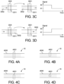
- sensor 3001 detects one signal level A 0 , as shown in FIG. 3A .
- sensor 3001 detects another signal level A 1 (A 0 ⁇ A 1 ), as shown in FIG. 3B .
- sensor 3001 measures a signal step of A 0 ⁇ A 1 when a fluid flows into sensing zone 3011 ( FIG. 3C ), and measures a signal step of A 1 ⁇ A 0 when a fluid flow out of sensing zone 3011 ( FIG. 3D ).
- a sensing zone may overlap different portions of the channel width.
- FIGS. 4A to 4D illustrate four examples, where sensing zone 4001 of sensing device 16 overlaps either the full width ( FIG. 4A ) or a partial width ( FIGS. 4B-4D ) of the channel.
- FIGS. 4B to D show that sensing zones smaller than the channel width can also be used for this method.
- each sensor of the sensing device can have a plurality of sensing zones along the length of the channel, as shown FIGS. 5A to 5I .
- one sensor 5100 of sensing device 18 has a plurality of m sensing zones, 5101, 5102 ... and 510 m ( m ⁇ 2 ) along the length of the fluid channel 5000 ( Fig.5A ).
- Sensor 5100 detects a signal level A 0 when there is no fluid in the sensing zones ( Fig.5B ).
- the sensor 5100 measures a signal A 1 ( Fig.5D ) that is distinctive from A 0 .
- the sensor 5100 measures a signal level A 2 ( Fig.5F ).
- the sensor 5100 measures a signal level A. ( Fig.5H ).
- the intensity of the sensing signal can be used to determine how many sensing zones are detecting fluid. This design can be achieved, for one example, by using a sensing signal that is proportional to the number of the sensing zones detecting fluid.
- the disclosed sensing device can measure a signal step of A i ⁇ A j , when a fluid flows in the channel and changes from filling i sensing zones to filling j sensing zones ( 0 ⁇ i ⁇ j ⁇ m ) .
- sensor 5100 measures a signal step of A 2 ⁇ A 3 when a fluid flows in the channel and changes from filling two sensing zones flows to filling three sensing zones.
- sensor 5100 measures a signal step of A 3 ⁇ A 2 when fluid flows in the channel and changes from filling three sensing zones flows to filling two sensing zones
- the design of one sensor with a plurality of sensing zones can be advantageous in comparison to the design of multiple sensors that each has one sensing zone.
- one design is to use a sensor with ten sensing zones, as compared to a design using ten sensors each having one sensing zone.
- the design of one sensor with a plurality of sensing zones has the advantages of simplified sensing hardware. This advantage is further elaborated in the example of Fig. 17 as discussed in below.
- the fluid channel has a channel width between 1 ⁇ m and 1 mm, a channel depth between 1 ⁇ m and 1 mm, and a channel length between 100 ⁇ m and 100 mm.
- the maximum volume of the sensing device is in the range from 100 fL to 100 ⁇ L.
- the fluid channel has a channel width between 0.01 ⁇ m and 1 ⁇ m, a channel depth between 0.01 ⁇ m and 1 ⁇ m, and a channel length between 1 ⁇ m and 100 ⁇ m.
- the maximum volume of the sensing device is in the range from 0.0001 fL to 100 fL.
- the fluid channel has a channel width between 1 mm and 10 mm, a channel depth between 1 mm and 10 mm, and a channel length between 100 mm and 1,000 mm.
- the maximum volume of the sensing device is in the range from 100 ⁇ L to 100 mL.
- the channel width can be from about 0.001 mm to about 0.05 mm, about 0.05 mm to about 1 mm, or about 1 mm to about 5 mm
- the channel height can be from about 0.001 mm to about 0.01 mm, about 0.01 mm to about 0.5 mm, about 0.5 um to about 1 mm, or about 1 mm to about 2 mm.
- each sensor of the sensing device can have a plurality of sensing zones along the width of the channel, as shown FIGS. 6A and 6B .
- one or more of the above-described sensors can be added to a fluidic cartridge or device for accepting a fluidic cartridge.
- Each sensor can be electrically connected to a control unit, which can then control fluid flow and/or provide user feedback based on signals from the sensors.
- the control unit can, for example, by determining the presence or absence of fluid at each fluid sensing zone, determine parameters of a particular fluid sample and control pumps and valves to stop fluid flow and/or run a test on the fluid sample when an appropriate amount of fluid has been transferred through the flow channel. The specific parameters determined by the control unit are discussed in more detail below.
- FIGS 7A to 7F show examples of these embodiments, which include a sensing device 22 with a plurality of ten sensors 7001, 7002 ... 7010 that each has one sensing zone.
- the channel length between any of the two neighboring sensors is L 1
- the channel volume between any of the two neighboring sensors is V 1 .
- a fluid plug 7100 with volume V (V>0) is flowing into the fluid channel 7000 (along the indicated direction) for volume measurement, as shown in Fig. 7B .
- Scenario 1 0 ⁇ V ⁇ V 1 .
- the sensor 7002 and sensor 7001 cannot detect fluid simultaneously. This is because of the volume of the fluid plug (V ⁇ V 1 ) is less than the channel volume between the sensors 7001 and 7002 (V 1 ).
- Scenario 2 V 1 ⁇ V ⁇ 2V 1 .
- the sensor 7002 and sensor 7001 can detect fluid simultaneously, but sensor 7003 and sensor 7001 can not detect fluid simultaneously.
- Scenario 3 2V 1 ⁇ V ⁇ 3V 1 .
- the sensor 7003, sensor 7002 and sensor 7001 can detect fluid simultaneously, but sensor 7004 and sensor 7001 can not detect fluid simultaneously
- sensor 700N, 700(N-1) ... and sensor 7001 can detect fluid simultaneously, but sensor 700(N+1) and sensor 7001 cannot detect fluid simultaneously.
- sensor 7010, 7009, ... and 7001 can all detect fluid simultaneously ( Fig.7F ).
- sensing device 22 can measure the volume of a fluid plug in the range of 0 to10V 1 with a resolution of V 1 .
- Sensing device 22 can also be operated in other ways that would be understood by persons skilled in the art based on the present disclosure.
- fluid plug can flow in a direction reserve to the direction shown in Fig.7 .
- the measureable volume range of the sensing device can be increased.
- sensing device 22 can measure a volume range from 0 to 100V 1 by using 100 sensors along the channel.
- the measurement resolution can be increased..
- the measurement resolution can be increased to 0.5V 1 .
- sensing device 22 uses 10 individual sensors that each has 1 sensing zone. Similar sensing function can be achieved by an alternative sensing device 24 that uses 1 sensor 8000 with 10 sensing zones 8001, 8002, ... and 8010, as shown in Figs. 8A and 8B . Sensing device 24 measures the volume of a fluid plug by monitoring the number of sensing zones filled with fluid, as shown in Fig.8B .
- the resolution of the volume measurement is limited to the volume V 1 between two neighboring sensors or sensing zones.
- Particular embodiments of the sensing design are also taught in this disclosure to increase resolution.
- FIG. 9A shows one example of these embodiments.
- Sensing device 26 comprises a plurality of 10 sensors 9001, 9002, ... and 9010.
- the volume between two neighboring sensors is designed to be incremental as 1.1V 1 , 1.2V 1 , 1.3V 1 ... and 1.9V 1 .
- sensor 9005 and sensor 9006 can detect fluid simultaneously ( Fig.9B ) whereas sensors 9006 and 9007 cannot detect fluid simultaneously ( Fig.9C ).
- sensing device 26 can distinguish a fluid plug with a volume of 1.5V 1 versus 1.6V 1 , achieving a measurement resolution of 0.1V 1 . This measurement resolution is smaller than the minimal volume between neighboring sensors (1.1V 1 ) in the sensing device 24.
- the sensing device above can measure a fluid plug volume with a resolution of 0.2V 1 , by considering two sensors that has one sensor in between, such as the sensors 9001 and 9003, as the "neighboring" sensors. Similarly, this sensing device can measure fluid plug volume with a resolution of 0.3V 1 , by considering two sensors that has two sensors in between, such as the sensors 9001 and 9004, as the "neighboring" sensors
- sensing devices can include one sensor with a plurality of sensing zones.
- FIG. 10 shows one example of a sensing device 28 comprising one sensor 10000 with a plurality of ten sensing zones 10001, 10002 ... and 10010.
- the channel volumes between the neighboring sensors are 1.1V 1 , 1.2V 1 ... and 1.9V 1 .
- sensing device 28 Similar to the sensing device 26 in Fig. 9A , sensing device 28 also measures the volume range from 1.0V 1 to 1.9V 1 with a resolution of 0.1V 1 .
- the maximum volume measureable on the sensing design 22 is 10V 1 , which is proportional to the number of sensors or the number of the sensing zones.
- a sensing device with a larger number of sensors or sensing zones will be needed, e.g., with 100 sensing zones.
- This configuration will significantly increase the hardware complexity.
- Particular embodiments can be used to increase the maximum volume, without using too many sensors and sensing zones.
- FIG. 11A shows one example of these embodiments.
- Sensing device 30 comprises of a plurality of 6 sensors along the channel length. Between the neighboring sensors 11001 and 11002, the channel volume is V 0 . The channel volume between other neighboring sensors, e.g.
- sensor 11002 and 11003 is V 1 (V 0 >V 1 ).
- sensors 11001 and 11002 can detect fluid simultaneously ( Fig.11B ).
- sensors 11001, 11002 and 11003 can detect fluid simultaneously ( Fig.11C ).
- sensors 11001, 11002, 11003 and 11004 can detect fluid simultaneously ( Fig.11D ). In this way, this sensing device design can measure a volume from V 0 to V 0 +4V 1 with a measurement resolution of V 1 .
- a sensing device 32 having one sensor with a plurality of six sensing zones 12001, 12002 ... and 12006 can also measure the volume range from V 0 to V 0 +4V 1 with the resolution of V 1 , as show in FIG. 12 .
- the channel volume between the sensing zones 12001 and 12002 is V 0
- the channel volume between other neighboring sensing zones is V 1 .
- one or more of the above-described sensors can be added to a fluidic cartridge or device for accepting a fluidic cartridge.
- Each sensor can be electrically connected to a control unit, which can then control fluid flow and/or provide user feedback based on signals from the sensors.
- the control unit can, for example, by determining the presence or absence of fluid at each fluid sensing zone, determine the volume discussed above and control pumps and valves to stop fluid flow based on the determined volume.
- FIGS. 13A to 13C show one example of these embodiments, in which sensing device 34 comprises of a plurality of ten sensors 13001, 13002 ... and 13010 along the channel length, and each sensor has one sensing zone.
- the channel length between two neighboring sensors is L 1
- the channel volume between two neighboring sensors is V 1 ( FIG.13 ).
- a continuous fluid 13000 flows through the channel for volume sensing as shown in Fig. 13B .
- Sensor 13001 detects the time point T 1 when the fluid flow reaches its sensing zone.
- Sensor 13002 detects the time point T 2 when the fluid flow reaches its sensing zone.
- the volume displacement of the fluid is (N-1)V 1
- sensing device 34 can comprise one sensor with a plurality of sensing zones to measure the fluid's volume displacement, flow rate and flow velocity.
- FIG. 14 shows one example of these embodiments, in which sensing device 36 comprises one sensor 14000 that has a plurality of 10 sensing zones 14001, 14002 ... and 14010 along the channel length. The channel length between two neighboring sensors is L1, and the channel volume between two neighboring sensors is V1. Sensing device 36 can make measurements in the same way described above for sensing device 34.
- one or more of the above-described sensors can be added to a fluidic cartridge or device for accepting a fluidic cartridge.
- Each sensor can be electrically connected to a control unit, which can then control fluid flow and/or provide user feedback based on signals from the sensors.
- the control unit can, for example, by determining the presence or absence of fluid at each fluid sensing zone, determine the volume displacement, flow rate and/or flow velocity discussed above and control pumps and valves to stop fluid flow and/or run a test on the fluid sample based on the determined volume displacement, flow rate and/or flow velocity.
- the controller can also note time points when the signals are taken and determine volume displacement, flow rate and/or flow velocity using the time points.
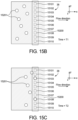
- FIG. 15A shows one example embodiment, in which sensing device 38 comprises of one sensor 15100 with a plurality of 10 sensing zones 15101, 15102 ... and 15110 along the width (y-axis) of fluid channel 15000.
- Each sensing zone has a same size and interacts with only one segment of the channel width, detecting whether the sensing zone is filled with air (no fluid) versus with fluid.
- N is the total number of the sensing zones and is equal to ten in this example.
- a fluid 15200 containing a plurality of air bubbles 15201 flows into the channel.
- T2 Fig.15C
- the senor continuously monitors the volume ratio of air bubble in the fluid.
- the accuracy of the volume ratio measurement can be increased using a larger number of the sensing zones along the channel width.
- one or more of the above-described sensors can be added to a fluidic cartridge or device for accepting a fluidic cartridge.
- Each sensor can be electrically connected to a control unit, which can then control fluid flow and/or provide user feedback based on signals from the sensors.
- the control unit can, for example, by determining the presence or absence of fluid at each fluid sensing zone, determine the bubble measurement discussed above and control pumps and valves to stop fluid flow and/or run a test on the fluid sample based on the determined bubble measurement.
- the geometry of the sensing zones and the fluid channels can be optimized for cartridge analysis. It is often desirable to insert disposable cartridges into a reader instrument for measurements.
- a sensor 16001 of the sensing device 40 can be built into the reader instrument, whereas the fluid channel 16000 is located on the cartridge, as shown in Fig.16A . Therefore, it is necessary to properly align the fluid channel 16000 with the sensor 16001 after insertion to achieve accurate sensing measurement, as shown in Fig.16B . Tolerance of the alignment helps to improve repeatability of the sensing measurement.
- the first type is the alignment tolerance along the channel width (y-axis).
- Fig.16C and Fig.16D show examples of aligned or misaligned sensing devices, depending on whether the sensing zone 16101 is covering the full width of the channel 16000.
- the width of the sensing zone 16010 W S can be designed wider than the width of the fluid channel 16000 Wc, as shown in Fig.16E . In this way, it can achieve an alignment tolerance of (Ws-Wc) in the width direction, as shown in Fig.16F .
- the second type is the alignment tolerance along the channel length (x-axis) direction. This is particularly important for sensing devices that have two or more sensing zones or sensors.
- An example of a sensing device 41 with two sensors 16001 and 16002 is shown in Fig.16G .
- the distance between the two sensors L 0 is fixed in the reader instrument, and thus kept as constant during the insertion step.
- the sensing device is considered misaligned if the channel volume between the two sensors is changed.
- Fig.16I shows a more complex example where the fluid channel has non-constant cross section area (A ⁇ A'). Nevertheless, the two channel segments can be designed for alignment with the two sensing zones to have a constant cross section area A. These two segments have a length of L C . In this way, the total volume between the two sensors can be kept as constant, while allowing an alignment tolerance of L C along the channel length direction (x-axis), as shown in Fig.16J .
- FIGS. 17A to 17C shows embodiments of the sensing device to demonstrate advantages of a sensing device with one sensor having multiple sensing zones versus sensing device with multiple sensors each having one sensing zone.
- Fig.17A is a sensing device 42 with six sensors 17001 to 17006, each having one sensing zone respectively. This design has six sensing zones from 17101 to 17106.
- Fig.17B is a sensing device 44 with one sensor 17007 having six sensing zones from 17101 to 17106. Using the one sensor design 44 helps to simplify the hardware configuration.
- Fig.17C is another sensing device 46 with one sensor 17008 having six sensing zones from 17101 to 17106.
- sensing device 46 achieves more compact a sensor area in comparison to the example of Fig.17B .
- the achievable size of the sensor area is limited by physician embodiments of the sensor. For example, if a photodiode is used for measuring optical signal in the sensing device. The surface area of the photodiode is limited, and thus it is advantageous to arrange the sensing zones within a compact size.
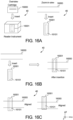
- FIG. 18A shows an example of a sensing device 40 with one sensor 18100 that has a plurality of three sensing zones 18101, 18102 and 18103 along the length of fluid channel 18000.
- the channel length is along the x-axis and the channel width is along the y-axis.
- FIG. 18B shows one example embodiment of the structure of sensing device 48.
- sensor 18100 is a sensing pair at two sides of the channel along the z-axis.
- Fluid channel 18000 is on a disposable cartridge.
- the sensing pair 18100 includes an external component that is separate from the disposable cartridge.
- the sensing zones are defined with components integrated on the cartridge, components separated from the cartridge and/or components integrated on the sensing pair.
- the sensing pair includes a light source and a light detector, the sensing signal is intensity of transmitted light and the sensing zones are defined by light masking apertures.
- FIG. 18C shows another example embodiment of the structure of sensing device 48.
- sensor 18100 includes a sensing pair at one side of the channel along the z-axis. Fluid channel 18000 is on a disposable cartridge.
- the sensing pair 18100 is an external component that is separate from the disposable cartridge.
- the sensing zones are defined with components integrated on the cartridge, components separated from the cartridge and/or components integrated on the sensing pair.
- the sensing pair includes a light source and a light detector, and the sensing signal is intensity of reflected light and the sensing zones are defined with light masking apertures.
- Fig. 18D shows another example embodiment of the structure of sensing device 48.
- sensor 18100 includes a sensing pair at two sides of the channel along the z-axis. Both the sensing pair 18100 and the fluid channel 18000 are on a disposable cartridge.
- the sensing zone is defined either with the effective zones of the sensing signals or components integrated on the disposable cartridge.
- the sensing pair includes a pair of electrodes, the sensing signal is electrical impedance, and the sensing zones are defined with apertures of electrical insulation layers.
- Fig. 18E shows yet another example embodiment of the structure of sensing device 48.
- sensor 18100 includes a sensing pair at one side of the channel along the z-axis. Both the sensing pair 18100 and the fluid channel 18000 are on a disposable cartridge.
- the sensing zone is defined either with the effective zones of the sensing signals or components integrated on the disposable cartridge.
- the sensing pair includes a pair of electrodes, the sensing signal is the amount of electrical charges in the fluid, and the sensing zones are defined with apertures of electrical insulation layers.
- the sensing devices described herein can use different sensing signals to detect whether there is fluid in the channel.
- the sensing signals include but not limit to optical signal, electrical signals, acoustic signals and thermal signals, etc.
- the sensing signals can be optical signals.
- the sensor could comprise of a pair of light source and light detector.
- the light source emits a light signal that interacts with a fluid in the channel and is then detected by the light detector.
- the sensing zone is defined as the effective zone of the light signal and/or an extra optical aperture.
- the detected light has distinct levels when there is fluid in the sensing zone of the channel versus when there is not.
- Examples of the light source include an LED, laser diode, light bulb, ambient light, etc.
- Examples of the light detector include a photodiode, avalanche photodiode, photomultiplier tube, CCD sensor, CMOS sensor, etc.
- the detected light signals include intensity of transmitted light, intensity of absorbed light, intensity of reflected light, intensity of fluorescence, intensity of chemiluminescence, polarization of light, etc.
- the light source is an LED
- the light detector is a photodiode
- the detected signal is the intensity of the transmitted/absorbed light.
- the sensing signal can be transmitted light.
- Figs.19A to 19C show one example of the sensing device 50 that utilize the transmitted light as the sensing signal.
- the sensor 19001 consist a light emitter 19001-1 and a light detector 19001-2.
- the sensing zone 19101 is defined with an aperture where light can pass through and interact with the channel.
- the light signal from the emitter 19001-1 passes through the aperture, interacts with the fluid channel, and is measured in the detector 19001-2, as shown in Fig.19C .
- the detector measures the intensity of transmitted light, and the sensing device use this signal to determine if there is fluid versus no fluid (e.g. air) in the sensing zone of the channel.
- the change of the transmitted light signal is caused by light absorption of the fluid sample, as shown in the example of sensing device 51 in Fig.19D .
- the detector 19001-2 measures a transmitted light intensity A0.
- the detector 19002-2 measures another transmitted light intensity A1.
- the fluid can absorb a significant part of the transmitted light. Therefore, the detected signal A1 is less than A0.
- the detectable signal difference (A0-A1) is determined by the amount of the light absorbed by the fluid.
- the fluid sample examples include, for example, water, biological fluids (blood, serum, plasma, urine, etc.), biological fluids diluted with buffer, etc.
- the light absorption and thus maximize the detectable signal difference (A1-A0) can be maximized.
- blood sample absorbs strongly the light in the green wavelength (e.g. 520-560nm). Therefore, using the green light wavelength can introduce a significant signal difference (A0-A1).
- the amount of light absorbed can be increased, and thus increase the detectable signal difference (A1-A0) as well.
- the light path length will be decreased and thus decrease the detectable signal difference (A1-A0).
- the change of the transmitted light is mainly caused by light scattering at the channel inner surface, as shown with sensing device 52 in Fig.19E .
- part of the light is scattered at the channel inner surface (interface between the channel material, e.g. plastic or glass, and the content inside the channel, e.g. air or fluid) and is not received in the sensor's detector.
- the higher the level of light scattering the lower the amount of light received in the detector, thus leading to a lower measured signal level.
- there is no fluid in the sensing zone of the channel e.g.
- the detector 19001-2 measures a lower transmitted light intensity A0.
- the detector 19002-2 measures a higher transmitted light intensity A1.
- the sensor can measure the signal difference (A0-A1) to determine if the sensing zone has fluid or has no fluid (e.g. is filled with air).
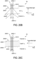
- Fig.20 further illustrates how this sensor design with light scattering works.
- Fig.20A shows a sensing device 53 that measures the transmitted light as the sensing signal.
- the light from the sensor's emitter 20001-1 illuminates perpendicularly on the channel's inner surface 20401 and 20402.
- surfaces 20401 and 20402 are perfectly smooth, there is no light scattering and all the light can be transmitted to the sensor's detector 20001-2, which detects a high signal level of A'.
- Fig.20B shows a similar sensing device 54 with the difference that the channel's inner surfaces 20401 and 20402 have a certain roughness.
- the channel material has a refractive index (n 1 ) that is not equal to the refractive index of air in the channel (n 0 )
- part of the light from the sensor's emitter 20001-1 is scattered at the rough surface and the sensor's detector 20001-2 detects a decreased signal level A0.
- n 1 refractive index
- the channel materials can be plastics such as Cyclic Olefin Copolymer (COC, refractive index near 1.53), Cyclic Olefin Polymer (COP, refractive index near 1.53), polycarbonate (PC, refractive index near 1.59), Polymethyl Methacrylate (PMMA, refractive near 1.49), Polyethylene Terephthalate (PEF refractive index near 1.60), Polystyrene (PS, refractive index near 1.6), and other plastic materials known to a person of ordinary skill in the art.
- COC Cyclic Olefin Copolymer
- COP Cyclic Olefin Polymer
- PC Polycarbonate
- PMMA Polymethyl Methacrylate
- PMMA Polyethylene Terephthalate
- PS Polystyrene
- the sensing device design is suitable for detecting various fluid samples that have refractive index (n 2 ) in the range of 1.3 to 1.65, such as water, analyte solution in water, body fluid (blood, urine, tear, etc.), body fluid solution in solvent, and other fluid samples known to person skilled in the art.
- the sensing device has a roughness of the channel inner surface in the range of Sa from 0.1nm to 10nm. In other preferred embodiments, the sensing device has a roughness of the channel inner surface in the range of Sa from 10nm to 1um. In other preferred embodiments, the sensing device has a roughness of the channel inner surface in the range of Sa from 1um to 10um. In other preferred embodiments, the sensing device has a roughness of the channel inner surface in the range of Sa from 10um to 100um.
- the light scattering design is significantly different from the previous embodiments of measuring light absorption as the sensing signal.
- the sensor design with light scattering measures a signal increase (A0 ⁇ A1) when detecting fluid (replacing air or vacuum) in the channel, whereas the sensor design with light absorption measures a signal decrease (A0>A1).
- the amplitude of signal difference (A0-A1) in the sensor design with light scattering is mostly determined by two design factors: the surface roughness of the channel inner surface and the refractive index mismatch between the channel material and the content inside the channel (air versus fluid).
- the amplitude of signal difference (A0-A1) in the sensor design with light absorption is mostly determined by another two factors: the attenuation coefficient ⁇ of the fluid and the length of the light path (e.g. the depth of channel along the z-axis in Fig.19 ).
- the light path length is limited by the channel size, and thus the amplitude of the measureable signal difference (A0-A1) is limited.
- the sensor design with light scattering is advantageous, because its signal difference (A0-A1) is determined mainly by the surface roughness and refractive index mismatch. Therefore, even a small channel size can introduce significant light scattering, by properly choosing the channel surface roughness and matching the refractive index between the channel material and the fluid sample.
- A0-A1 In practical use, light absorption and light scattering often exist simultaneously in the sensing device. Their relative impact on the signal difference (A0-A1) can be optimized by designing the channel dimension, fluid sample property (attenuation coefficient ⁇ , concentration of analyte in the sample c, refractive index n 2 ), channel material (refractive index n 1 ), channel surface roughness (Sa), light wavelength and other properties known to person skilled in the art.
- the sensing signals could be electrical signals.
- the sensor could comprise of a pair of electrodes.
- the electrical field generated by the electrode pair can interact with a fluid in the channel.
- the sensing zone is defined as the effective zone of the electrical field and/or an insulation aperture.
- the detected signals at the electrode pair have distinct levels when there is fluid in the sensing zone of the channel versus when there is not. Examples of the detected electrical signals include but not limit to values of electrical impedance (e.g. resistance, capacitance, inductance), amplitudes of AC/DC current, amplitudes of AD/DC voltages, frequency spectrum of the current/voltage, etc.
- the sensing signals could be acoustic signals.
- the sensor comprises of a pair of an acoustic source and an acoustic detector.
- the acoustic signal from the source interacts with a fluid in the channel.
- the sensing zone is defined as the effective zone of the acoustic field and/or an acoustic aperture.
- the detected signals have distinct levels when there is fluid in the sensing zone of the channel versus when there is not. Examples of the detected acoustic signals include but not limited to intensity of the acoustic wave, and/or frequency of the acoustic wave.
- the sensing signals are thermal signals.
- the sensor comprises a pair of a thermal source and a thermal detector.
- the thermal signal from the source interacts with a fluid in the channel.
- the sensing zone is defined as the effective zone of the thermal pathway and/or a thermal insulation aperture.
- the detected signals have distinct levels when there is fluid in the sensing zone of the channel versus when there is not. Examples of the detected thermal signals include temperature.
Description
- The present disclosure relates generally to methods and apparatuses for measuring parameters of a fluid sample within a disposable cassette, and more specifically to measuring parameters based on the presence or absence of fluid at a plurality of fluid sensing zones.
- For analysis of biological samples, it is often desirable to use only a small sample volume. Therefore, a precise measurement of the volume could be crucial to the analysis accuracy. In the applications of point-of-care testing (POCT), the analysis of biological samples is preferably conducted in a disposable cartridge, which has the merits of ease of use and avoids cross-contamination from other samples. However, sensing volume in cartridges imposes new challenges particularly to measure a small volume with high accuracy. For example, the complexity of the cartridge limits the available choices of volume sensing methods.
- Normally these cartridges use passive methods such as volumetric chambers to determine the fluid volume taken for analysis. The accuracy of these passive methods suffers from unpredicted variations, such as user operations (e.g. the volumetric chamber is not filled up properly or contains bubbles). These variations are particularly ubiquitous in POCT applications, where users replace cartridges before each analysis.
- A document D1
US 2002/042125 A1 discloses a method for separating an analyte from a fluid sample and for concentrating the analyte into a volume of elution fluid. A document D2US 2004/0005247 A1 discloses microfluidic devices and methods for metering discrete plugs of fluid. A document D3US 2008/273918 A1 discloses fluidic connectors, methods, and devices for performing analyses (e.g., immunoassays) in microfluidic systems. A document D4US 2003/005967 A1 discloses systems and methods for metering microfluidic volumes. A document D5US 2009/266421 A1 discloses microfluidic systems and methods including those that provide control of fluid flow. A document D6US 2007/003434 A1 discloses a hematology analyzer or cytometer cartridge system having flow metering. It may have on- or off-cartridge flow metering and control. A document D7US 6 549 275 B1 discloses an optical detection system for flow cytometry. A document D8US 2012/190589 A1 discloses an assay cartridge that may be used to conduct a biological assay in a cartridge reader. - The present disclosure uses an active sensing method to determine the fluid volume in-situ. Active sensing methods can accurately measure the fluid volume taken for analysis. However, hardware of the active sensing methods may add to the complexity and manufacturing cost of the cartridges. For a small sample volume in the
range 1 nL to 1 mL, which is common in biological analysis, it is even more challenging to design a sensing method that delivers high accuracy with low hardware complexity for cartridges. Thus, the present disclosure is directed to a novel and more effective device for measuring and analyzing fluid volume. - In a general example embodiment, the invention provides a fluidic device defined by any one of the appended
claims 1 to 12. The following embodiments listed in paragraphs [0006] to [0043] are not according to the claimed invention, but useful for understanding the invention. - In another embodiment, the plurality of fluid sensing zones are spaced along a length of the fluid channel when the disposable cartridge is received by the instrument.
- In another embodiment, the plurality of fluid sensing zones are spaced along a width of the fluid channel when the disposable cartridge is received by the instrument.
- In another embodiment, the plurality of fluid sensing zones are each located on separate sensors configured to measure the presence or absence of fluid at the respective portion of the fluid channel along the length of the fluid channel.
- In another embodiment, the plurality of fluid sensing zones are each located on the same sensor, and wherein the fluid channel has a winding shape through the disposable cartridge, and wherein the plurality of fluid sensing zones are aligned with sections of fluid channel that converge into a centralized portion of the sensor.
- In another embodiment, the control unit is configured to determine the volume displacement of the fluid within the fluid channel based on the presence or absence of the fluid at each of the fluid sensing zones, wherein the fluid flowing through the fluid channel passes along the fluid sensing zones sequentially.
- In another embodiment, the control unit is configured to determine the flow rate of the fluid within the fluid channel based on the presence or absence of the fluid at each of the fluid sensing zones, wherein the fluid flowing through the fluid channel passes along the fluid sensing zones sequentially.
- In another embodiment, the control unit is configured to determine the volume of a fluid plug within the fluid channel based on the presence or absence of the fluid at each of the fluid sensing zones, wherein the fluid flowing through the fluid channel passes along the fluid sensing zones sequentially.
- In another embodiment, the fluid channel has a known cross-sectional area, and wherein the control unit uses the known cross-sectional area of the fluid channel to determine at least one of the fluid volume, the volume displacement, the flow rate or the flow velocity of the fluid based on the presence or absence of the fluid at each of the fluid sensing zones.
- In a general embodiment, a fluidic device includes a disposable cartridge including a fluid channel configured to receive a fluid flow, an instrument configured to receive the disposable cartridge, the instrument including at least one sensor having a plurality of fluid sensing zones spaced along a length of the fluid channel when the disposable cartridge is received by the instrument, each sensor including a light emitter and a light receiver, and a control unit configured to determine the presence or absence of fluid at each of the fluid sensing zones based on the light transmission from the respective emitter to the respective receiver in each sensor, wherein the level of light transmission is changed by the amount of light scattered with presence or absence of fluid in the fluid sensing zone.
- In another embodiment, the controller is configured to use a surface roughness of at least a portion of the fluid channel to determine the presence or absence of fluid at each of the fluid sensing zones, wherein the surface roughness changes the amount of light scattered in each sensor.
- In another embodiment, the controller is configured to use a refractive index of a material forming at least a portion of the fluid channel to determine the presence or absence of fluid at each of the fluid sensing zones, wherein the difference between the refractive index of the material and the refractive index of fluid in the channel changes the amount of light scattered in each sensor.
- In another embodiment, the controller is configured to determine at least one of a fluid volume, a volume displacement, a flow rate, a flow velocity or a volume ratio of gas bubbles of the fluid based on the presence or absence of the fluid at each of the fluid sensing zones.
- In a general embodiment, a method of configuring a disposable cartridge includes designing a disposable cartridge to have a fluid channel configured to receive a particular fluid sample, forming at least a portion of the fluid channel with a surface roughness using a material having a refractive index that matches the refractive index of the particular fluid sample, and configuring the portion of the fluid channel to align with a light emitter and a light receiver in a reader instrument when the disposable cartridge is received in the instrument for measurements.
- In another embodiment, the method includes programming the reader instrument to determine the presence or absence of fluid in the fluid channel of the disposable cartridge based on the light transmission from the respective emitter to the respective receiver, wherein the level of light transmission is changed by the amount of light scattered when there is a presence or absence of fluid in the channel.
- In another embodiment, the method includes configuring the portion of the fluid channel to align with a plurality of light emitters and light receiver along the width of the fluid channel.
- In another embodiment, the method includes configuring the portion of the fluid channel to align with a plurality of light emitters and light receivers along the length of the fluid channel.
- In another embodiment, the method includes programming the reader instrument to determine at least one of a fluid volume, a volume displacement, a flow rate, a flow velocity or a volume ratio of gas bubbles of the fluid based on the presence or absence of the fluid at each of the plurality of light emitters and light receivers.
- In another embodiment, the method includes designing the fluid channel with a winding shape through the disposable cartridge so that each of the plurality of light emitters and light receivers are aligned with sections of the fluid channel in the disposable cartridge that are converged into a centralized portion.
- In another embodiment, the method includes allowing for an alignment tolerance when aligning the plurality of light emitters and light receivers with the fluid channel in the cartridge by fixing the distance between the plurality of light emitters and light receivers before alignment.
- In a general embodiment, a fluidic device includes a fluid channel configured to receive a fluid flow, a plurality of fluid sensing zones spaced along a length of the fluid channel, each fluid sensing zone configured to determine a presence or absence of fluid at a respective portion of the fluid channel along the length of the fluid channel, and a control unit configured to (i) receive a signal indicative of the presence or absence of the fluid at each of the fluid sensing zones, and (ii) determine at least one of a fluid volume, a volume displacement, a flow rate or a flow velocity of the fluid based on the presence or absence of the fluid at each of the fluid sensing zones
- In another embodiment, the control unit is configured to determine the fluid volume of the fluid within the flow channel based on the presence or absence of the fluid at each of the fluid sensing zones.
- In another embodiment, the control unit is configured to determine the volume displacement of the fluid within the flow channel based on the presence or absence of the fluid at each of the fluid sensing zones.
- In another embodiment, the control unit is configured to determine the flow rate of the fluid within the flow channel based on the presence or absence of the fluid at each of the fluid sensing zones.
- In another embodiment, the control unit is configured to determine the flow velocity of the fluid within the flow channel based on the presence or absence of the fluid at each of the fluid sensing zones.
- In another embodiment, the control unit uses a known cross-sectional area of the fluid channel to determine at least one of the fluid volume, the volume displacement, the flow rate or the flow velocity of the fluid based on the presence or absence of the fluid at each of the fluid sensing zones.
- In another embodiment, the fluidic channel is located on a disposable cassette made at least partly of a transparent material.
- In another embodiment, the plurality of fluid sensing zones are each located on separate sensors configured to measure the presence or absence of fluid at the respective portion of the fluid channel along the length of the fluid channel.
- In another embodiment, the fluid sensing zones are configured to determine the presence or absence of fluid at a respective portion of the fluid channel along the length of the fluid channel using at least one of: (i) optical signals; (ii) electrical signals; (iii) acoustic signals; and (iv) thermal signals.
- In a general embodiment, a fluidic device includes a fluid channel configured to receive a fluid flow, a plurality of fluid sensing zones spaced along a width of the fluidic channel, each fluid sensing zone configured to determine a presence or absence of fluid at a respective portion of the fluid channel along the width of the fluid channel, and a control unit configured to configured to (i) receive a signal indicative of the presence or absence of the fluid at each of the fluid sensing zones, and (ii) determine a quantity of air bubbles versus liquid within the fluid channel based on the presence or absence of the fluid at each of the fluid sensing zones.
- In another embodiment, the control unit is configured to determine the quantity of air bubbles versus liquid within the fluid channel using widths of the plurality of fluid sensing zones.
- In another embodiment, the control unit is configured to determine the quantity of air bubbles versus liquid within the fluid channel using a length of the fluid channel.
- In a general embodiment, a method of monitoring fluid flow through a fluid channel includes aligning a plurality of fluid sensing zones with a length or a width of a fluid channel of a disposable cartridge, detecting a presence or absence of fluid at the plurality of fluid sensing zones, determining a parameter of the fluid based on the presence or absence of the fluid at each of the fluid sensing zones, and controlling flow of the fluid through the fluid channel of the disposable cartridge based on the determined parameter
- In another embodiment, determining a parameter includes determining a fluid volume of the fluid based on the presence or absence of the fluid at each of the fluid sensing zones.
- In another embodiment, determining a parameter includes determining a volume displacement of the fluid based on the presence or absence of the fluid at each of the fluid sensing zones.
- In another embodiment, determining a parameter includes determining a flow rate of the fluid based on the presence or absence of the fluid at each of the fluid sensing zones.
- In another embodiment, determining a parameter includes determining a flow velocity of the fluid based on the presence or absence of the fluid at each of the fluid sensing zones.
- In another embodiment, determining a parameter includes determining a quantity of air bubbles versus liquid within the fluid channel of the fluid based on the presence or absence of the fluid at each of the fluid sensing zones.
- In another embodiment, allowing for an alignment tolerance when aligning the plurality of fluid sensing zones by fixing the distance between the plurality of fluid zones before alignment.
- Embodiments of the present disclosure will now be explained in further detail by way of example only with reference to the accompanying figures, in which:
-
FIG. 1 depicts, in accordance with embodiments herein, an example embodiment of a sensing device. In the example embodiment ofFIG. 1 , when a fluid enters the fluid channel, the sensors measure the length of the channel that is filled with the fluid. The fluid volume is determined with the measured length and the known geometry of the channel. -
FIG. 2 depicts, in accordance with embodiments herein, an example embodiment of a sensing device. -
FIGS. 3A to 3D depict, in accordance with embodiments herein, an example embodiment of a sensing device. -
FIGS. 4A to 4D depict, in accordance with embodiments herein, an example embodiment of a sensing device. -
FIGS. 5A to 5I depict, in accordance with embodiments herein, an example embodiment of a sensing device. -
FIGS. 6A and 6B depict, in accordance with embodiments herein, an example embodiment of a sensing device. -
FIGS. 7A to 7F depict, in accordance with embodiments herein, an example embodiment of a sensing device. -
FIGS. 8A and 8B depict, in accordance with embodiments herein, an example embodiment of a sensing device. -
FIGS. 9A to 9E depict, in accordance with embodiments herein, an example embodiment of a sensing device. -
FIG. 10 depicts, in accordance with embodiments herein, an example embodiment of a sensing device. -
FIGS. 11A to 11D depict, in accordance with embodiments herein, an example embodiment of a sensing device. -
FIG. 12 depicts, in accordance with embodiments herein, an example embodiment of a sensing device. -
FIGS. 13A to 13D depict, in accordance with embodiments herein, an example embodiment of a sensing device. -
FIG. 14 depicts, in accordance with embodiments herein, an example embodiment of a sensing device. -
FIGS. 15A to 15C depict, in accordance with embodiments herein, an example embodiment of a sensing device. -
FIGS. 16A to 16J depict, in accordance with embodiments herein, an example embodiment of a sensing device. -
FIGS. 17A to 17C depicts, in accordance with embodiments herein, an example embodiment of a sensing device. -
FIGS. 18A to 18E depict, in accordance with embodiments herein, an example embodiment of a sensing device. -
FIGS. 19A to 19E depict, in accordance with embodiments herein, an example embodiment of a sensing device. -
FIGS. 20A to 20C depict, in accordance with embodiments herein, an example embodiment of a sensing device. - All references cited herein are incorporated by reference in their entirety as though fully set forth. Unless defined otherwise, technical and scientific terms used herein have the same meaning as commonly understood by one of ordinary skill in the art to which this disclosure belongs. Hornyak, et al., Introduction to Nanoscience and Nanotechnology, CRC Press (2008); Singleton et al., Dictionary of Microbiology and Molecular Biology 3rd ed., J. Wiley & Sons (New York, NY 2001); March, Advanced Organic Chemistry Reactions, Mechanisms and Structure 7th ed., J. Wiley & Sons (New York, NY 2013); and Sambrook and Russel, Molecular Cloning: A Laboratory Manual 4th ed., Cold Spring Harbor Laboratory Press (Cold Spring Harbor, NY 2012), provide one skilled in the art with a general guide to many of the terms used in the present application. One skilled in the art will recognize many methods and materials similar or equivalent to those described herein, which could be used in the practice of the present disclosure. Indeed, the present disclosure is in no way limited to the methods and materials described.
- As described herein, various sensing designs were developed to overcome some of the challenges faced when analyzing samples using only a small sample volume, and specifically including cartridges.
- In an embodiment, the present disclosure provides an active sensing method for determining fluid volume where a device comprising one or more sensors along the length of a fluidic channel is used to determine a fluid volume. In another embodiment, the present disclosure provides a device comprising one or more sensors along the length of a fluidic channel to determine a fluid volume. In another embodiment, the device is used to measure the volume displacement of a fluid flow. In another embodiment, the device is used to measure flow rate. In another embodiment, the device is used to measure flow velocity. In another embodiment, the device is used to determine the volume ratio of gas bubbles mixed in a fluid.
- In an embodiment, the present disclosure provides a device comprising a plurality of sensors along the length of a fluidic channel. When a fluid enters the channel, the sensors measure the channel length that is filled up with the fluid. In an embodiment, from the measured length and the known geometry of the channel, a control unit can determine the fluid volume in the fluid channel. In an embodiment, the present disclosure provides a high accuracy of sensing small volumes by using a microfluidic channel that has a narrow cross-section so as to elongate the fluid length for measurement. In an embodiment, the channel width can be from about 0.001 mm to about 0.05mm, about 0.05 mm to about 1 mm, or about 1 mm to about 5 mm, and the channel height can be from about 0.001 mm to about 0.01 mm, about 0.01 mm to about 0.5 mm, about 0.5 um to about 1 mm, or about 1 mm to about 2 mm.
- In an embodiment, one or more sensors has a sensing zone that overlaps with the channel. In an embodiment, a sensor detects two distinct levels of a sensing signal, when there is fluid in the sensing zone versus when there is not. The transition of the signal from one level to another indicates a fluid flow into or away from the sensing zone. In an embodiment, the sensing zone has a geometry that is equal to, larger than or smaller than the width of the fluidic channel. In an embodiment, each sensor has a plurality of sensing zones along the channel length, and can detect a plurality of distinct levels of the sensing signal, corresponding to the number of the sensing zones filled with fluid. The signal transition from one level to another indicates a fluid flow that fills more or less number of the sensing zones. In an embodiment, each sensor has a plurality of sensing zones along the channel width, and can detect a plurality of distinct levels of the sensing signal, which correspond to the number of the sensing zones filled with fluid. In an embodiment, the signal level is measured to determine the volume ratio of gas bubbles in a fluid flow.
- As further disclosed herein, various embodiments may be used to measure the volume of a fluid plug, and volume displacement, flow rate and flow velocity of a fluid moving along the sensing channel. In another embodiment, particular arrangements of sensing zones may be used to improve the resolution of volume sensing beyond the geometry limitation of the fluidic channel. In another embodiment, the present disclosure provides measurements of the volume ratio of gas bubbles in a fluid sample.
- In an embodiment, the geometry of the sensing zones is optimized to increase the alignment tolerance between the sensor and the fluidic channel. In an embodiment, the sensing zones can have a width that is slightly larger then the channel width interacting with the sensing zones, so as to increase alignment tolerance along the channel width direction. For example, the sensing zone width can be 200% of the channel width, which has an alignment tolerance of ± 50% of the channel width. In other embodiments, the sensing zone width can be in the range of 100% to 300% of the channel width, or 300% to 500% of the channel width. In another embodiment, the geometry of the fluidic channel is optimized to minimize the area of the sensor that is required to include the sensing zones. For example, in an embodiment of a sensor with multiple sensing zones, the channel geometry can have a meander shape to minimize the sensor area.
- In an embodiment, the present disclosure may be modified to provide various sensing signals. For example, while not limited to any particular example, there are may various physical signals that could be used in sensing signals. For example, physical signals may include optical signals, electrical signals, acoustic signals, and/or thermal signals. In an embodiment, there may be further structural modifications, including for example an embodiment wherein the fluidic channel is an integrated component of a cartridge while the sensors are external components separated from the cartridges. Or, for example, an embodiment wherein both the fluidic channel and the sensors are integrated components of the cartridges.
- The present disclosure is also directed to a kit for determining fluid volume. The kit is useful for practicing method described herein of analyzing a biological sample, for example. The kit is an assemblage of materials or components, including at least one of the compositions described herein. Thus, in some embodiments the kit contains a composition including solution and media.
- The exact nature of the components configured in the inventive kit depends on its intended purpose. For example, some embodiments are configured for the purpose of diagnosing a disease or condition, or as part of an overall treatment regimen. In one embodiment, the kit is configured particularly for the purpose of diagnosing mammalian subjects. In another embodiment, the kit is configured particularly for the purpose of diagnosing human subjects. In further embodiments, the kit is configured for veterinary applications, diagnosing or treating subjects such as, but not limited to, farm animals, domestic animals, and laboratory animals.
- Instructions for use may be included in the kit. "Instructions for use" typically include a tangible expression describing the technique to be employed in using the components of the kit to effect a desired outcome, such as to analyze a biological sample. Optionally, the kit also contains other useful components, such as, diluents, buffers, pharmaceutically acceptable carriers, syringes, catheters, applicators, pipetting or measuring tools, bandaging materials or other useful paraphernalia as will be readily recognized by those of skill in the art.
- The materials or components assembled in the kit can be provided to the practitioner stored in any convenient and suitable ways that preserve their operability and utility. For example, the components can be in dissolved, dehydrated, or lyophilized form; they can be provided at room, refrigerated or frozen temperatures. The components are typically contained in suitable packaging material(s). As employed herein, the phrase "packaging material" refers to one or more physical structures used to house the contents of the kit, such as inventive compositions and the like. The packaging material is constructed by well known methods, preferably to provide a sterile, contaminant-free environment. As used herein, the term "package" refers to a suitable solid matrix or material such as glass, plastic, paper, foil, and the like, capable of holding the individual kit components. Thus, for example, a package can be a glass vial used to contain suitable quantities of an inventive composition containing solution or media. The packaging material generally has an external label which indicates the contents and/or purpose of the kit and/or its components.
- The various methods and techniques described above provide a number of ways to carry out the disclosure. Of course, it is to be understood that not necessarily all objectives or advantages described may be achieved in accordance with any particular embodiment described herein. Thus, for example, those skilled in the art will recognize that the methods described herein can be performed in a manner that achieves or optimizes one advantage or group of advantages as taught herein without necessarily achieving other objectives or advantages as may be taught or suggested herein. Furthermore, the skilled artisan will recognize the applicability of various features from different embodiments. Similarly, the various elements, features and steps discussed above, as well as other known equivalents for each such element, feature or step, can be mixed and matched by one of ordinary skill in this art to perform methods in accordance with principles described herein.
- Although the disclosure has been disclosed in the context of certain embodiments and examples, it will be understood by those skilled in the art that the embodiments of the present disclosure extend beyond the specifically disclosed embodiments to other alternative embodiments and/or uses and modifications and equivalents thereof.
- Many variations and alternative elements have been disclosed in embodiments of the present disclosure. Still further variations and alternate elements will be apparent to one of skill in the art. Among these variations, without limitation, are the selection of constituent modules for the compositions described herein, and the diseases and other clinical conditions that may be diagnosed, prognosed or treated therewith.
- In some embodiments, the numbers expressing quantities of ingredients, properties such as concentration, reaction conditions, and so forth, used to describe and claim certain embodiments of the disclosure are to be understood as being modified in some instances by the term "about." Accordingly, in some embodiments, the numerical parameters set forth in the written description and attached claims are approximations that can vary depending upon the desired properties sought to be obtained by a particular embodiment. In some embodiments, the numerical parameters should be construed in light of the number of reported significant digits and by applying ordinary rounding techniques. Notwithstanding that the numerical ranges and parameters setting forth the broad scope of some embodiments of the disclosure are approximations, the numerical values set forth in the specific examples are reported as precisely as practicable. The numerical values presented in some embodiments of the disclosure may contain certain errors necessarily resulting from the standard deviation found in their respective testing measurements.
- In some embodiments, the terms "a" and "an" and "the" and similar references used in the context of describing a particular embodiment of the disclosure (especially in the context of certain of the following claims) can be construed to cover both the singular and the plural forms. The recitation of ranges of values herein is merely intended to serve as a shorthand method of referring individually to each separate value falling within the range. Unless otherwise indicated herein, each individual value is incorporated into the specification as if it were individually recited herein. All methods described herein can be performed in any suitable order unless otherwise indicated herein or otherwise clearly contradicted by context. The use of any and all examples, or exemplary language (e.g. "such as") provided with respect to certain embodiments herein is intended merely to better illuminate the disclosure and does not pose a limitation on the scope of the disclosure otherwise claimed. No language in the specification should be construed as indicating any non-claimed element essential to the practice of the disclosure.
- Groupings of alternative elements or embodiments of the disclosure disclosed herein are not to be construed as limitations. Each group member can be referred to and claimed individually or in any combination with other members of the group or other elements found herein. One or more members of a group can be included in, or deleted from, a group for reasons of convenience and/or patentability. When any such inclusion or deletion occurs, the specification is herein deemed to contain the group as modified thus fulfilling the written description of all Markush groups used in the appended claims.
- Preferred embodiments of the present disclosure are described herein, including the best mode known for carrying out the disclosure. Variations on those preferred embodiments will become apparent to those of ordinary skill in the art upon reading the foregoing description. It is contemplated that skilled artisans can employ such variations as appropriate, and the disclosure can be practiced otherwise than specifically described herein. Accordingly, many embodiments of this disclosure include all modifications and equivalents of the subject matter recited in the claims appended hereto as permitted by applicable law. Moreover, any combination of the above-described elements in all possible variations thereof is encompassed by the disclosure unless otherwise indicated herein or otherwise clearly contradicted by context.
- Furthermore, numerous references have been made to patents and printed publications throughout this specification. Each of the above cited references and printed publications are herein individually incorporated by reference in their entirety.
- It is to be understood that the embodiments of the disclosure disclosed herein are illustrative of the principles of the present disclosure. Other modifications that can be employed can be within the scope of the disclosure. Thus, by way of example, but not of limitation, alternative configurations of the present disclosure can be utilized in accordance with the teachings herein. Accordingly, embodiments of the present disclosure are not limited to that precisely as shown and described.
- The following examples are provided to better illustrate the claimed disclosure and are not to be interpreted as limiting the scope of the disclosure. To the extent that specific materials are mentioned, it is merely for purposes of illustration and is not intended to limit the disclosure. One skilled in the art may develop equivalent means or reactants without the exercise of inventive capacity and without departing from the scope of the disclosure.
- In one embodiment, a
sensing device 10 according to the present disclosure comprises of a plurality ofsensors FIG. 1 herein, which are positioned along the length of afluidic channel 1000. Eachsensor fluidic channel 1000. When a fluid enters thefluidic channel 1000, thesensors fluidic channel 1000. - For a given volume of fluid, the narrower the cross-section of the
fluidic channel 1000, the longer the length of the fluid-filledfluidic channel 1000 for measurement. Therefore, it is preferable forfluidic channel 1000 ofsensing device 10 to have a narrow cross-section, so that a high accuracy and high resolution sensing of a small volume can be achieved. In an embodiment, asensor fluidic channel 1000. By measuring time points, flow rate and flow velocity of the fluid, for example, can be determined with the known channel geometry. In preferred embodiments,sensing device 10 can be used to measure a fluid volume in the range of 1 nL to 1 mL.Sensing device 10 is preferably used in a cartridge for analysis of fluid samples. - In some embodiments, each
sensor sensing device 10 has one sensing zone that detects the fluid in the channel.FIG. 2 herein shows an example of asensing device 12 with a plurality ofsensors respective sensing zone sensing zone fluid channel 2000 to detect any fluid that flows throughfluid channel 2000. Alternatively, any one or more ofsensing zone fluid channel 2000, for example, a top portion or a bottom portion. - An example of the operation of a
sensor 3001 is shown inFIGS. 3A to 3D . As illustrated,sensor 3001 ofsensing device 14 has asensing zone 3011 that overlaps afluid channel 3000 of a disposable cassette. When there is no fluid in thesensing zone 3011,sensor 3001 detects one signal level A0, as shown inFIG. 3A . When sensingzone 3011 is filled with fluid 3002,sensor 3001 detects another signal level A1 (A0≠A1), as shown inFIG. 3B . In this way,sensor 3001 measures a signal step of A0→A1 when a fluid flows into sensing zone 3011 (FIG. 3C ), and measures a signal step of A1→A0 when a fluid flow out of sensing zone 3011 (FIG. 3D ). - In various embodiments, a sensing zone may overlap different portions of the channel width.
FIGS. 4A to 4D illustrate four examples, wheresensing zone 4001 ofsensing device 16 overlaps either the full width (FIG. 4A ) or a partial width (FIGS. 4B-4D ) of the channel.FIGS. 4B to D show that sensing zones smaller than the channel width can also be used for this method. - In other embodiments, each sensor of the sensing device can have a plurality of sensing zones along the length of the channel, as shown
FIGS. 5A to 5I . InFIG. 5A , onesensor 5100 ofsensing device 18 has a plurality of m sensing zones, 5101, 5102 ... and 510m (m≥2) along the length of the fluid channel 5000 (Fig.5A ).Sensor 5100 detects a signal level A0 when there is no fluid in the sensing zones (Fig.5B ). When afluid sample 5002 enters the channel and fills up the first sensing zone 5101 (Fig.5C ), thesensor 5100 measures a signal A1 (Fig.5D ) that is distinctive from A0. When thefluid sample 5002 continuously enters the channel and filter up bothsensing zones 5101 and sensing zones 5102 (Fig.5E ), thesensor 5100 measures a signal level A2 (Fig.5F ). When thefluid sample 5002 continuously enters the channel and fills up sensingzones 5101 to sensingzones 510m (Fig.5G ), thesensor 5100 measures a signal level A. (Fig.5H ). In general, the sensor detects a signal level Ak when there is fluid in k sensing zones (0≤k≤m), where signal levels Ak are distinct from each other for k=0, 1, 2, ..., m (Fig.5I ). The intensity of the sensing signal can be used to determine how many sensing zones are detecting fluid. This design can be achieved, for one example, by using a sensing signal that is proportional to the number of the sensing zones detecting fluid. - The disclosed sensing device can measure a signal step of Ai→Aj, when a fluid flows in the channel and changes from filling i sensing zones to filling j sensing zones (0≤i≠j≤m). For example,
sensor 5100 measures a signal step of A2→A3 when a fluid flows in the channel and changes from filling two sensing zones flows to filling three sensing zones. In another example,sensor 5100 measures a signal step of A3→A2 when fluid flows in the channel and changes from filling three sensing zones flows to filling two sensing zones - For certain applications, the design of one sensor with a plurality of sensing zones can be advantageous in comparison to the design of multiple sensors that each has one sensing zone. For example, to cover the measurement of ten sensing zones along the channel length, one design is to use a sensor with ten sensing zones, as compared to a design using ten sensors each having one sensing zone. The design of one sensor with a plurality of sensing zones has the advantages of simplified sensing hardware. This advantage is further elaborated in the example of
Fig. 17 as discussed in below. - In an embodiment, the fluid channel has a channel width between 1 µm and 1 mm, a channel depth between 1 µm and 1 mm, and a channel length between 100 µm and 100 mm. For these examples, the maximum volume of the sensing device is in the range from 100 fL to 100 µL. For yet other examples, the fluid channel has a channel width between 0.01 µm and 1 µm, a channel depth between 0.01 µm and 1 µm, and a channel length between 1 µm and 100 µm. For these examples, the maximum volume of the sensing device is in the range from 0.0001 fL to 100 fL. For yet other examples, the fluid channel has a channel width between 1 mm and 10 mm, a channel depth between 1 mm and 10 mm, and a channel length between 100 mm and 1,000 mm. For these examples, the maximum volume of the sensing device is in the range from 100 µL to 100 mL. In an embodiment, the channel width can be from about 0.001 mm to about 0.05 mm, about 0.05 mm to about 1 mm, or about 1 mm to about 5 mm, and the channel height can be from about 0.001 mm to about 0.01 mm, about 0.01 mm to about 0.5 mm, about 0.5 um to about 1 mm, or about 1 mm to about 2 mm.
- In another embodiment, each sensor of the sensing device can have a plurality of sensing zones along the width of the channel, as shown
FIGS. 6A and 6B . InFIG. 6A ,sensor 6100 of sensing device 20 has a plurality of m sensing zones, 6101, 6102 ... and 610m (m≥2) along the width offluid channel 6000. Similar to the example ofFig.5 ,sensor 6100 detects a signal level A0 when there is no fluid in the sensing zones, and detects a signal level Ak when there is fluid in k sensing zones (0≤k≤m). Signal levels Ak are distinct from each other for k = 0, 1, 2, ...m (Fig. 6B ). With this configuration, the sensor's signal level can measure the ratio of the channel width that is filled with fluid versus the width that is not, e.g. the width occupied by gas bubbles, as shown in the example ofFig. 15 as discussed below. - In an embodiment, one or more of the above-described sensors can be added to a fluidic cartridge or device for accepting a fluidic cartridge. Each sensor can be electrically connected to a control unit, which can then control fluid flow and/or provide user feedback based on signals from the sensors. The control unit can, for example, by determining the presence or absence of fluid at each fluid sensing zone, determine parameters of a particular fluid sample and control pumps and valves to stop fluid flow and/or run a test on the fluid sample when an appropriate amount of fluid has been transferred through the flow channel. The specific parameters determined by the control unit are discussed in more detail below.
- Particular embodiments of the sensing devices described herein can be used to measure the volume of a fluid plug.
FIGS 7A to 7F show examples of these embodiments, which include asensing device 22 with a plurality of tensensors Fig.7A , the channel length between any of the two neighboring sensors is L1, and the channel volume between any of the two neighboring sensors is V1.A fluid plug 7100 with volume V (V>0) is flowing into the fluid channel 7000 (along the indicated direction) for volume measurement, as shown inFig. 7B . - Scenario 1: 0<V<V1. As the fluid plug flows through the channel (
Fig.7C ), thesensor 7002 andsensor 7001 cannot detect fluid simultaneously. This is because of the volume of the fluid plug (V<V1) is less than the channel volume between thesensors 7001 and 7002 (V1). - Scenario 2: V1≤V<2V1. As the fluid plug flows through the channel (
Fig.7D ), thesensor 7002 andsensor 7001 can detect fluid simultaneously, butsensor 7003 andsensor 7001 can not detect fluid simultaneously. - Scenario 3: 2V1≤V<3V1. As the fluid plug flows through the channel (
Fig.7E ), thesensor 7003,sensor 7002 andsensor 7001 can detect fluid simultaneously, butsensor 7004 andsensor 7001 can not detect fluid simultaneously - In general, for the scenario of (N-1)V1≤V<NV1 (N=2,3,4,...9), as the fluid plug flows through the channel, sensor 700N, 700(N-1) ... and
sensor 7001 can detect fluid simultaneously, but sensor 700(N+1) andsensor 7001 cannot detect fluid simultaneously. - In the scenario V≥10V1, as the fluid plug flows through the channel,
sensor Fig.7F ). - By monitoring the sensing signal of the sensors,
sensing device 22 can measure the volume of a fluid plug in the range of 0 to10V1 with a resolution of V1. -
Sensing device 22 can also be operated in other ways that would be understood by persons skilled in the art based on the present disclosure. For example, fluid plug can flow in a direction reserve to the direction shown inFig.7 . By increasing the number of sensors, the measureable volume range of the sensing device can be increased. For example,sensing device 22 can measure a volume range from 0 to 100V1 by using 100 sensors along the channel. By decreasing the channel volume V1 between the neighboring sensors, the measurement resolution can be increased.. For example, by decreasing the neighboring volume from V1 to 0.5V1, the measurement resolution can be increased to 0.5V1. - In the illustrated embodiment,
sensing device 22 uses 10 individual sensors that each has 1 sensing zone. Similar sensing function can be achieved by analternative sensing device 24 that uses 1sensor 8000 with 10sensing zones Figs. 8A and 8B .Sensing device 24 measures the volume of a fluid plug by monitoring the number of sensing zones filled with fluid, as shown inFig.8B . - In the above two examples, the resolution of the volume measurement is limited to the volume V1 between two neighboring sensors or sensing zones. Particular embodiments of the sensing design are also taught in this disclosure to increase resolution.
FIG. 9A shows one example of these embodiments.Sensing device 26 comprises a plurality of 10sensors fluid plug 9100 with a volume 1.5V1 flows into the channel,sensor 9005 andsensor 9006 can detect fluid simultaneously (Fig.9B ) whereassensors Fig.9C ). When afluid plug 9101 with a volume 1.6 V1 flows into the channel,sensor 9006 andsensor 9007 can detect fluid simultaneously (Fig.9D ) whereassensors Fig.9E ). In this way, sensingdevice 26 can distinguish a fluid plug with a volume of 1.5V1 versus 1.6V1, achieving a measurement resolution of 0.1V1. This measurement resolution is smaller than the minimal volume between neighboring sensors (1.1V1) in thesensing device 24. - Additionally, the sensing device above can measure a fluid plug volume with a resolution of 0.2V1, by considering two sensors that has one sensor in between, such as the
sensors sensors - In further embodiments, sensing devices can include one sensor with a plurality of sensing zones.
FIG. 10 shows one example of asensing device 28 comprising onesensor 10000 with a plurality of tensensing zones sensing device 26 inFig. 9A , sensingdevice 28 also measures the volume range from 1.0V1 to 1.9V1 with a resolution of 0.1V1. - In the example of
Fig.7A , the maximum volume measureable on thesensing design 22 is 10V1, which is proportional to the number of sensors or the number of the sensing zones. To measure a larger volume, for example 100V1, a sensing device with a larger number of sensors or sensing zones will be needed, e.g., with 100 sensing zones. This configuration will significantly increase the hardware complexity. Particular embodiments can be used to increase the maximum volume, without using too many sensors and sensing zones.FIG. 11A shows one example of these embodiments.Sensing device 30 comprises of a plurality of 6 sensors along the channel length. Between the neighboringsensors e.g. sensor sensors Fig.11B ). When a fluid plug with a volume of V0+V1 flows through the channel,sensors Fig.11C ). When a fluid plug with a volume of V0+2V1 flows through the channel,sensors Fig.11D ). In this way, this sensing device design can measure a volume from V0 to V0+4V1 with a measurement resolution of V1. - Similarly, a
sensing device 32 having one sensor with a plurality of sixsensing zones FIG. 12 . In this example embodiment, the channel volume between thesensing zones - In an embodiment, one or more of the above-described sensors can be added to a fluidic cartridge or device for accepting a fluidic cartridge. Each sensor can be electrically connected to a control unit, which can then control fluid flow and/or provide user feedback based on signals from the sensors. The control unit can, for example, by determining the presence or absence of fluid at each fluid sensing zone, determine the volume discussed above and control pumps and valves to stop fluid flow based on the determined volume.
- Particular embodiments of the sensing devices herein can be used to measure the volume displacement of a fluid flow.
FIGS. 13A to 13C show one example of these embodiments, in whichsensing device 34 comprises of a plurality of tensensors FIG.13 ). Acontinuous fluid 13000 flows through the channel for volume sensing as shown inFig. 13B .Sensor 13001 detects the time point T1 when the fluid flow reaches its sensing zone.Sensor 13002 detects the time point T2 when the fluid flow reaches its sensing zone. From time T1 to T2, the volume displacement of the fluid flow is V1, which is measured by the channel volume betweensensors - In other embodiments,
sensing device 34 can comprise one sensor with a plurality of sensing zones to measure the fluid's volume displacement, flow rate and flow velocity.FIG. 14 shows one example of these embodiments, in whichsensing device 36 comprises onesensor 14000 that has a plurality of 10sensing zones Sensing device 36 can make measurements in the same way described above for sensingdevice 34. - In an embodiment, one or more of the above-described sensors can be added to a fluidic cartridge or device for accepting a fluidic cartridge. Each sensor can be electrically connected to a control unit, which can then control fluid flow and/or provide user feedback based on signals from the sensors. The control unit can, for example, by determining the presence or absence of fluid at each fluid sensing zone, determine the volume displacement, flow rate and/or flow velocity discussed above and control pumps and valves to stop fluid flow and/or run a test on the fluid sample based on the determined volume displacement, flow rate and/or flow velocity. The controller can also note time points when the signals are taken and determine volume displacement, flow rate and/or flow velocity using the time points.
- Particular embodiments of the sensing device can be used to determine the volume ratio of air bubbles mixed in a fluid.
FIG. 15A shows one example embodiment, in whichsensing device 38 comprises of onesensor 15100 with a plurality of 10sensing zones fluid channel 15000. Each sensing zone has a same size and interacts with only one segment of the channel width, detecting whether the sensing zone is filled with air (no fluid) versus with fluid. The channel has a constant height along z-axis. Therefore, the number of sensing zones detecting gas N1 can be used to estimate the bubble ratio as: bubble ratio RB= N1/N. N is the total number of the sensing zones and is equal to ten in this example. - For example, a fluid 15200 containing a plurality of air bubbles 15201 flows into the channel. At time t=T1 (
Fig.15B ), no sensing zone detects air in the channel (N1=0). Therefore, the bubble ratio RB(t=T1) = 0/10 =0%. At time t=T2 (Fig.15C ), two sensing zones (15103, 15108) detects air in the channel (N1=2). Therefore, the bubble ratio RB(t=T2) = 2/10=20%. - As the fluid continuously flows through the channel, the sensor continuously monitors the volume ratio of air bubble in the fluid. The accuracy of the volume ratio measurement can be increased using a larger number of the sensing zones along the channel width.
- In an embodiment, one or more of the above-described sensors can be added to a fluidic cartridge or device for accepting a fluidic cartridge. Each sensor can be electrically connected to a control unit, which can then control fluid flow and/or provide user feedback based on signals from the sensors. The control unit can, for example, by determining the presence or absence of fluid at each fluid sensing zone, determine the bubble measurement discussed above and control pumps and valves to stop fluid flow and/or run a test on the fluid sample based on the determined bubble measurement.
- In particular embodiments, the geometry of the sensing zones and the fluid channels can be optimized for cartridge analysis. It is often desirable to insert disposable cartridges into a reader instrument for measurements. In an embodiment, a
sensor 16001 of thesensing device 40 can be built into the reader instrument, whereas thefluid channel 16000 is located on the cartridge, as shown inFig.16A . Therefore, it is necessary to properly align thefluid channel 16000 with thesensor 16001 after insertion to achieve accurate sensing measurement, as shown inFig.16B . Tolerance of the alignment helps to improve repeatability of the sensing measurement. - Two types of alignment tolerance are considered. The first type is the alignment tolerance along the channel width (y-axis).
Fig.16C andFig.16D show examples of aligned or misaligned sensing devices, depending on whether thesensing zone 16101 is covering the full width of thechannel 16000. To increase alignment tolerance, the width of the sensing zone 16010 WS can be designed wider than the width of thefluid channel 16000 Wc, as shown inFig.16E . In this way, it can achieve an alignment tolerance of (Ws-Wc) in the width direction, as shown inFig.16F . - The second type is the alignment tolerance along the channel length (x-axis) direction. This is particularly important for sensing devices that have two or more sensing zones or sensors. An example of a
sensing device 41 with twosensors Fig.16G . The distance between the two sensors L0 is fixed in the reader instrument, and thus kept as constant during the insertion step. The sensing device is considered misaligned if the channel volume between the two sensors is changed. By designing thefluid channel 16000 to have a cross section area A (Fig.16H ), the channel volume between the two sensors is always kept as a constant of V=AL0. In this way, the sensing device is easily achieving alignment by default.Fig.16I shows a more complex example where the fluid channel has non-constant cross section area (A≠A'). Nevertheless, the two channel segments can be designed for alignment with the two sensing zones to have a constant cross section area A. These two segments have a length of LC. In this way, the total volume between the two sensors can be kept as constant, while allowing an alignment tolerance of LC along the channel length direction (x-axis), as shown inFig.16J . -
FIGS. 17A to 17C shows embodiments of the sensing device to demonstrate advantages of a sensing device with one sensor having multiple sensing zones versus sensing device with multiple sensors each having one sensing zone.Fig.17A is asensing device 42 with sixsensors 17001 to 17006, each having one sensing zone respectively. This design has six sensing zones from 17101 to 17106.Fig.17B is asensing device 44 with onesensor 17007 having six sensing zones from 17101 to 17106. Using the onesensor design 44 helps to simplify the hardware configuration. -
Fig.17C is anothersensing device 46 with onesensor 17008 having six sensing zones from 17101 to 17106. By arranging the fluid channel in a meander shape, and by arranging the sensing zones in a compact configuration where flowpaths of the meander shape converge inward,sensing device 46 achieves more compact a sensor area in comparison to the example ofFig.17B . When using one sensor to cover a sensor area, the achievable size of the sensor area is limited by physician embodiments of the sensor. For example, if a photodiode is used for measuring optical signal in the sensing device. The surface area of the photodiode is limited, and thus it is advantageous to arrange the sensing zones within a compact size. - In particular embodiments, the sensing device described herein could have additional various structures. For example,
FIG. 18A shows an example of asensing device 40 with onesensor 18100 that has a plurality of threesensing zones fluid channel 18000. The channel length is along the x-axis and the channel width is along the y-axis. -
FIG. 18B shows one example embodiment of the structure ofsensing device 48. In the illustrated embodiment,sensor 18100 is a sensing pair at two sides of the channel along the z-axis.Fluid channel 18000 is on a disposable cartridge. Thesensing pair 18100 includes an external component that is separate from the disposable cartridge. The sensing zones are defined with components integrated on the cartridge, components separated from the cartridge and/or components integrated on the sensing pair. In an embodiment, the sensing pair includes a light source and a light detector, the sensing signal is intensity of transmitted light and the sensing zones are defined by light masking apertures. -
FIG. 18C shows another example embodiment of the structure ofsensing device 48. In the illustrated embodiment,sensor 18100 includes a sensing pair at one side of the channel along the z-axis.Fluid channel 18000 is on a disposable cartridge. Thesensing pair 18100 is an external component that is separate from the disposable cartridge. In an embodiment, the sensing zones are defined with components integrated on the cartridge, components separated from the cartridge and/or components integrated on the sensing pair. In an embodiment, the sensing pair includes a light source and a light detector, and the sensing signal is intensity of reflected light and the sensing zones are defined with light masking apertures. -
Fig. 18D shows another example embodiment of the structure ofsensing device 48. In the illustrated embodiment,sensor 18100 includes a sensing pair at two sides of the channel along the z-axis. Both thesensing pair 18100 and thefluid channel 18000 are on a disposable cartridge. In one embodiment, the sensing zone is defined either with the effective zones of the sensing signals or components integrated on the disposable cartridge. In an embodiment, the sensing pair includes a pair of electrodes, the sensing signal is electrical impedance, and the sensing zones are defined with apertures of electrical insulation layers. -
Fig. 18E shows yet another example embodiment of the structure ofsensing device 48. In the illustrated embodiment,sensor 18100 includes a sensing pair at one side of the channel along the z-axis. Both thesensing pair 18100 and thefluid channel 18000 are on a disposable cartridge. In one embodiment, the sensing zone is defined either with the effective zones of the sensing signals or components integrated on the disposable cartridge. In an embodiment, the sensing pair includes a pair of electrodes, the sensing signal is the amount of electrical charges in the fluid, and the sensing zones are defined with apertures of electrical insulation layers. - In accordance with various embodiments described herein, the sensing devices described herein can use different sensing signals to detect whether there is fluid in the channel. Examples of the sensing signals include but not limit to optical signal, electrical signals, acoustic signals and thermal signals, etc.
- In particular embodiments, the sensing signals can be optical signals. For example, the sensor could comprise of a pair of light source and light detector. The light source emits a light signal that interacts with a fluid in the channel and is then detected by the light detector. The sensing zone is defined as the effective zone of the light signal and/or an extra optical aperture. The detected light has distinct levels when there is fluid in the sensing zone of the channel versus when there is not. Examples of the light source include an LED, laser diode, light bulb, ambient light, etc. Examples of the light detector include a photodiode, avalanche photodiode, photomultiplier tube, CCD sensor, CMOS sensor, etc. Examples of the detected light signals include intensity of transmitted light, intensity of absorbed light, intensity of reflected light, intensity of fluorescence, intensity of chemiluminescence, polarization of light, etc. In an embodiment, the light source is an LED, the light detector is a photodiode and the detected signal is the intensity of the transmitted/absorbed light.
- In particular embodiments, the sensing signal can be transmitted light.
Figs.19A to 19C show one example of thesensing device 50 that utilize the transmitted light as the sensing signal. In this sensing device, as shown inFig.19B , thesensor 19001 consist a light emitter 19001-1 and a light detector 19001-2. Thesensing zone 19101 is defined with an aperture where light can pass through and interact with the channel. The light signal from the emitter 19001-1 passes through the aperture, interacts with the fluid channel, and is measured in the detector 19001-2, as shown inFig.19C . The detector measures the intensity of transmitted light, and the sensing device use this signal to determine if there is fluid versus no fluid (e.g. air) in the sensing zone of the channel. - In particular embodiments, the change of the transmitted light signal is caused by light absorption of the fluid sample, as shown in the example of
sensing device 51 inFig.19D . When there is no fluid (e.g. air) in the sensing zone of the channel, the detector 19001-2 measures a transmitted light intensity A0. When the channel is filled with fluid, the detector 19002-2 measures another transmitted light intensity A1. By choosing proper light wavelength, the fluid can absorb a significant part of the transmitted light. Therefore, the detected signal A1 is less than A0. The detectable signal difference (A0-A1) is determined by the amount of the light absorbed by the fluid. - The amount of light absorption can be determined by the Beer-Lambert Law: A = εbc, where A is the amount of light absorption, ε is the attenuation coefficient of the sample, b is the path length of the light absorption, and c is the concentration of analyte in the sample. For a given sample (fixed ε and c), the longer the light path length b is, the higher the amount of light being absorbed.
- Examples of the fluid sample include, for example, water, biological fluids (blood, serum, plasma, urine, etc.), biological fluids diluted with buffer, etc. By choosing the proper light wavelength for the targeted fluid (increasing the attenuation coefficient ε), the light absorption and thus maximize the detectable signal difference (A1-A0) can be maximized. For example, blood sample absorbs strongly the light in the green wavelength (e.g. 520-560nm). Therefore, using the green light wavelength can introduce a significant signal difference (A0-A1). Meanwhile, by increasing the channel height along the z-axis (increasing light path length b), the amount of light absorbed can be increased, and thus increase the detectable signal difference (A1-A0) as well. On the other hand, by decreasing the channel height along the z-axis, the light path length will be decreased and thus decrease the detectable signal difference (A1-A0).
- In other particular embodiments, the change of the transmitted light is mainly caused by light scattering at the channel inner surface, as shown with
sensing device 52 inFig.19E . When light transmitting from the sensor's emitter 19001-1 towards the sensor's detector 19002-2, part of the light is scattered at the channel inner surface (interface between the channel material, e.g. plastic or glass, and the content inside the channel, e.g. air or fluid) and is not received in the sensor's detector. The higher the level of light scattering, the lower the amount of light received in the detector, thus leading to a lower measured signal level. When there is no fluid in the sensing zone of the channel, e.g. air or vacuum in the channel, a higher level of light scattering is introduced and thus the detector 19001-2 measures a lower transmitted light intensity A0. When the channel is filled with fluid, a lower level of light scattering is introduced and thus the detector 19002-2 measures a higher transmitted light intensity A1. The sensor can measure the signal difference (A0-A1) to determine if the sensing zone has fluid or has no fluid (e.g. is filled with air). -
Fig.20 further illustrates how this sensor design with light scattering works.Fig.20A shows asensing device 53 that measures the transmitted light as the sensing signal. The light from the sensor's emitter 20001-1 illuminates perpendicularly on the channel'sinner surface Fig.20B shows asimilar sensing device 54 with the difference that the channel'sinner surfaces Fig.20C , it replaces the air (n0=1.0) and reduces the mismatch of refractive index with the channel material (plastic n1=1.3 to 1.7, or glass n1=1.4 to 1.7). Therefore, the amount of light scattered is reduced, and the sensor's detector measures an increased light signal A1 (A1>A0). In an ideal case, if the fluid sample's refractive index is equal to the channel material's refractive index (n3=n1), there is no scattering at the interface and the sensor's detector measures a maximum level of A1. - In view of above, in designing a sensing device with light scattering, it is important to consider the roughness of the inner surface of the channel and to consider the refractive index of the channel material as well as the fluid sample. In an embodiment, the channel materials can be plastics such as Cyclic Olefin Copolymer (COC, refractive index near 1.53), Cyclic Olefin Polymer (COP, refractive index near 1.53), polycarbonate (PC, refractive index near 1.59), Polymethyl Methacrylate (PMMA, refractive near 1.49), Polyethylene Terephthalate (PEF refractive index near 1.60), Polystyrene (PS, refractive index near 1.6), and other plastic materials known to a person of ordinary skill in the art. In an embodiment, the sensing device design is suitable for detecting various fluid samples that have refractive index (n2) in the range of 1.3 to 1.65, such as water, analyte solution in water, body fluid (blood, urine, tear, etc.), body fluid solution in solvent, and other fluid samples known to person skilled in the art. In preferred embodiments, the sensing device has a roughness of the channel inner surface in the range of Sa from 0.1nm to 10nm. In other preferred embodiments, the sensing device has a roughness of the channel inner surface in the range of Sa from 10nm to 1um. In other preferred embodiments, the sensing device has a roughness of the channel inner surface in the range of Sa from 1um to 10um. In other preferred embodiments, the sensing device has a roughness of the channel inner surface in the range of Sa from 10um to 100um.
- The light scattering design is significantly different from the previous embodiments of measuring light absorption as the sensing signal. First, the sensor design with light scattering measures a signal increase (A0<A1) when detecting fluid (replacing air or vacuum) in the channel, whereas the sensor design with light absorption measures a signal decrease (A0>A1). Second, the amplitude of signal difference (A0-A1) in the sensor design with light scattering is mostly determined by two design factors: the surface roughness of the channel inner surface and the refractive index mismatch between the channel material and the content inside the channel (air versus fluid). Meanwhile, the amplitude of signal difference (A0-A1) in the sensor design with light absorption is mostly determined by another two factors: the attenuation coefficient ε of the fluid and the length of the light path (e.g. the depth of channel along the z-axis in
Fig.19 ). - For cartridge applications with small fluid channel dimensions, the light path length is limited by the channel size, and thus the amplitude of the measureable signal difference (A0-A1) is limited. In this case, the sensor design with light scattering is advantageous, because its signal difference (A0-A1) is determined mainly by the surface roughness and refractive index mismatch. Therefore, even a small channel size can introduce significant light scattering, by properly choosing the channel surface roughness and matching the refractive index between the channel material and the fluid sample.
- In practical use, light absorption and light scattering often exist simultaneously in the sensing device. Their relative impact on the signal difference (A0-A1) can be optimized by designing the channel dimension, fluid sample property (attenuation coefficient ε, concentration of analyte in the sample c, refractive index n2), channel material (refractive index n1), channel surface roughness (Sa), light wavelength and other properties known to person skilled in the art.
- In yet other embodiments, the sensing signals could be electrical signals. For example, the sensor could comprise of a pair of electrodes. The electrical field generated by the electrode pair can interact with a fluid in the channel. In one embodiment, the sensing zone is defined as the effective zone of the electrical field and/or an insulation aperture. The detected signals at the electrode pair have distinct levels when there is fluid in the sensing zone of the channel versus when there is not. Examples of the detected electrical signals include but not limit to values of electrical impedance (e.g. resistance, capacitance, inductance), amplitudes of AC/DC current, amplitudes of AD/DC voltages, frequency spectrum of the current/voltage, etc.
- In other embodiments, the sensing signals could be acoustic signals. For example, in one embodiment, the sensor comprises of a pair of an acoustic source and an acoustic detector. The acoustic signal from the source interacts with a fluid in the channel. In an embodiment, the sensing zone is defined as the effective zone of the acoustic field and/or an acoustic aperture. The detected signals have distinct levels when there is fluid in the sensing zone of the channel versus when there is not. Examples of the detected acoustic signals include but not limited to intensity of the acoustic wave, and/or frequency of the acoustic wave.
- In other embodiments, the sensing signals are thermal signals. For example, in an embodiment, the sensor comprises a pair of a thermal source and a thermal detector. The thermal signal from the source interacts with a fluid in the channel. In an embodiment, the sensing zone is defined as the effective zone of the thermal pathway and/or a thermal insulation aperture. The detected signals have distinct levels when there is fluid in the sensing zone of the channel versus when there is not. Examples of the detected thermal signals include temperature.
- Various embodiments of the disclosure are described above in the Detailed Description. While these descriptions directly describe the above embodiments, it is understood that those skilled in the art may conceive modifications and/or variations to the specific embodiments shown and described herein. Any such modifications or variations that fall within the claims are intended to be included therein as well. Unless specifically noted, it is the intention of the inventors that the words and phrases in the specification and claims be given the ordinary and accustomed meanings to those of ordinary skill in the applicable art(s).
- The foregoing description of various embodiments of the disclosure known to the applicant at this time of filing the application has been presented and is intended for the purposes of illustration and description. The present description is not intended to be exhaustive nor limit the disclosure to the precise form disclosed and many modifications and variations are possible in the light of the above teachings. The embodiments described serve to explain the principles of the disclosure and its practical application and to enable others skilled in the art to utilize the disclosure in various embodiments and with various modifications as are suited to the particular use contemplated. Therefore, it is intended that the disclosure not be limited to the particular embodiments disclosed for carrying out the disclosure.
- While particular embodiments of the present disclosure have been shown and described, it will be obvious to those skilled in the art that, based upon the teachings herein, changes and modifications may be made without departing from this disclosure and its broader aspects defined by the appended claims. It will be understood by those within the art that, in general, terms used herein are generally intended as "open" terms (e.g., the term "including" should be interpreted as "including but not limited to," the term "having" should be interpreted as "having at least," the term "includes" should be interpreted as "includes but is not limited to," etc.).
Claims (12)
- A fluidic device comprising:a disposable cartridge including a fluid channel configured to receive a fluid flow;an instrument configured to receive the disposable cartridge, the instrument including at least one sensor (8000) that has two or more fluid sensing zones (8001, 8002) spaced along the fluid channel length when the disposable cartridge is received by the instrument, each fluid sensing zone configured to determine a presence or absence of fluid at a respective portion of the fluid channel; anda control unit configured to (i) receive a signal from the sensor (8000) that is indicative of the presence or absence of the fluid at each of the fluid sensing zones (8001, 8002), and (ii) determine at least one of a fluid volume, a volume of a fluid plug based on the determined presence or absence of fluid at each of the fluid sensing zones (8001, 8002).
- The fluidic device of claim 1, wherein the plurality of fluid sensing zones (17101, 17102) are each located on the same sensor (17007), wherein the fluid channel has a winding shape through the disposable cartridge, and wherein the plurality of fluid sensing zones (17101, 17102) are aligned with sections of the fluid channel that converge into a centralized portion of the sensor.
- The fluidic device of claim 1, wherein each sensor (19001) comprises a light emitter (19001-1) and a light receiver (19001-2).
- The fluidic device of claim 3, wherein the received signal measures the level of the light transmission from the respective light emitter (19001-1) to the respective light receiver (19001-2).
- The fluidic device of claim 4, wherein the fluid channel overlapping with the fluid sensing zones is configured to have a surface roughness that scatters at least a portion of the light transmission from the respective emitter (20001-1) to the respective receiver (20001-2).
- The fluidic device of claim 5, wherein the surface roughness of the fluid channel overlapping with the sensing zones is in the range of about 0.1 nm to 10 nm, 10 nm to 1 µm, 1 µm to 10 µm, or 10 µm to 100 µm.
- The fluidic device of claim 6, wherein the control unit is configured to determine a fluid entering a fluid sensing zone by detecting a changed level of the light transmission when there is presence or absence of fluid in the sensing zone.
- The fluidic device of claim 7, wherein the level of the light transmission increases from absence to presence of fluid in the sensing zone.
- The fluidic device of claim 3, wherein each sensor (18100) further comprises a plurality of light masking apertures (18101, 18102, 18103) defining the plurality of fluid sensing zones.
- The fluidic device of claim 9, wherein the sensor (18100) is a sensing pair including an external component that is separate from the disposable cartridge.
- The fluidic device of claim 1, wherein a material forming at least a portion of the fluid channel is configured to have a refractive index of about 1.3 to 1.7.
- The fluidic device of claim 1, wherein the instrument comprises two or more sensors, and the controller is configured to determine the volume displacement of the fluid flow or the volume of the fluid plug in the fluid channel by detecting a changed level of light transmission in a first sensor and a changed level of light transmission in a second sensor.
Applications Claiming Priority (2)
| Application Number | Priority Date | Filing Date | Title |
|---|---|---|---|
| US201562192488P | 2015-07-14 | 2015-07-14 | |
| PCT/US2016/042089 WO2017011554A1 (en) | 2015-07-14 | 2016-07-13 | Volume sensing in fluidic cartridge |
Publications (3)
| Publication Number | Publication Date |
|---|---|
| EP3322968A1 EP3322968A1 (en) | 2018-05-23 |
| EP3322968A4 EP3322968A4 (en) | 2019-07-03 |
| EP3322968B1 true EP3322968B1 (en) | 2024-02-21 |
Family
ID=57758283
Family Applications (1)
| Application Number | Title | Priority Date | Filing Date |
|---|---|---|---|
| EP16825111.4A Active EP3322968B1 (en) | 2015-07-14 | 2016-07-13 | Volume sensing in a fluidic cartridge |
Country Status (4)
| Country | Link |
|---|---|
| US (1) | US10077999B2 (en) |
| EP (1) | EP3322968B1 (en) |
| CN (1) | CN108027310B (en) |
| WO (1) | WO2017011554A1 (en) |
Families Citing this family (21)
| Publication number | Priority date | Publication date | Assignee | Title |
|---|---|---|---|---|
| US10634602B2 (en) | 2015-06-12 | 2020-04-28 | Cytochip Inc. | Fluidic cartridge for cytometry and additional analysis |
| WO2016200922A1 (en) | 2015-06-12 | 2016-12-15 | Cytochip Inc. | Fluidic units and cartridges for multi-analyte analysis |
| WO2017011554A1 (en) | 2015-07-14 | 2017-01-19 | Cytochip Inc. | Volume sensing in fluidic cartridge |
| EP3335027B1 (en) | 2015-08-13 | 2023-06-07 | Red Meters LLC | Apparatus and methods for determining gravity and density of solids in a liquid medium |
| US10928411B2 (en) * | 2017-04-21 | 2021-02-23 | 2Pi-Sigma Corporation | Automated medical sample collection and testing |
| US11103163B2 (en) | 2017-04-21 | 2021-08-31 | 2Pi-Sigma Corporation | Test cartridge and lancet for automated medical sample collection and testing |
| US10816545B2 (en) | 2017-04-21 | 2020-10-27 | 2Pi-Sigma Corporation | Automated medical sample collection, testing, and analysis |
| US11175303B2 (en) | 2017-04-21 | 2021-11-16 | 2Pi-Sigma Corp. | Automated medical sample collection and testing for providing blood coagulation indication |
| US11202593B2 (en) | 2017-04-21 | 2021-12-21 | 2Pi-Sigma Corp. | Adjustable lancet and test cartridge for automated medical sample collection and testing |
| US10791972B2 (en) * | 2017-04-21 | 2020-10-06 | 2Pi-Sigma Corporation | Fluid measurement for automated medical sample collection and testing |
| US11371866B2 (en) * | 2017-05-17 | 2022-06-28 | Red Meters LLC | Methods for designing a flow conduit and apparatus that measures deflection at multiple points to determine flow rate |
| WO2019083844A1 (en) | 2017-10-23 | 2019-05-02 | Cytochip Inc. | Devices and methods for measuring analytes and target particles |
| DE102017127145B4 (en) * | 2017-11-17 | 2021-03-04 | BEDIA Motorentechnik GmbH & Co. KG | Device and method for capacitive measurement of a fill level of a filling medium |
| US20210069708A1 (en) * | 2018-02-12 | 2021-03-11 | Hewlett-Packard Development Company, L.P. | Microfluidic flow sensor |
| US11920967B2 (en) | 2018-11-19 | 2024-03-05 | Kyocera Corporation | Optical fluid detection sensor for detecting flow of immiscible slug flow in a fluid detection device |
| WO2020247676A1 (en) | 2019-06-07 | 2020-12-10 | Life Technologies Corporation | Line volume calibration systems and methods |
| CN111505173B (en) * | 2020-06-12 | 2020-12-08 | 赛默飞世尔(上海)仪器有限公司 | Method for determining liquid flow, fraction collector and liquid chromatography system |
| CN111426777B (en) * | 2020-06-12 | 2020-11-27 | 赛默飞世尔(上海)仪器有限公司 | Method for determining pipeline volume, liquid chromatography system and pipeline volume determining device |
| CN114001798A (en) * | 2020-07-28 | 2022-02-01 | 恩普乐股份有限公司 | Fluid processing device, fluid processing system, and liquid detection method |
| CN113694981B (en) * | 2021-07-26 | 2022-09-02 | 中铁六局集团呼和浩特铁路建设有限公司 | Auxiliary equipment for cement density detection and use method thereof |
| CN113866047B (en) * | 2021-10-21 | 2024-04-02 | 南京信息工程大学 | Viscosity coefficient optical measurement device and method based on machine learning |
Citations (2)
| Publication number | Priority date | Publication date | Assignee | Title |
|---|---|---|---|---|
| US6549275B1 (en) * | 2000-08-02 | 2003-04-15 | Honeywell International Inc. | Optical detection system for flow cytometry |
| US20120190589A1 (en) * | 2009-12-07 | 2012-07-26 | Meso Scale Technologies, Llc. | Assay Cartridges and Methods of Using the Same |
Family Cites Families (82)
| Publication number | Priority date | Publication date | Assignee | Title |
|---|---|---|---|---|
| SE8801299L (en) | 1988-04-08 | 1989-10-09 | Bertil Hoeoek | MICROMECHANICAL ONE-WAY VALVE |
| US4983523A (en) | 1988-04-08 | 1991-01-08 | Gene-Trak Systems | Methods for preparing sample nucleic acids for hybridization |
| US5096669A (en) | 1988-09-15 | 1992-03-17 | I-Stat Corporation | Disposable sensing device for real time fluid analysis |
| US5110724A (en) | 1990-04-02 | 1992-05-05 | Cholestech Corporation | Multi-analyte assay device |
| US5213965A (en) | 1990-07-16 | 1993-05-25 | Cholestech Corporation | Solid-phase precipitation assay device |
| US6905882B2 (en) | 1992-05-21 | 2005-06-14 | Biosite, Inc. | Diagnostic devices and apparatus for the controlled movement of reagents without membranes |
| US5478750A (en) | 1993-03-31 | 1995-12-26 | Abaxis, Inc. | Methods for photometric analysis |
| US6235531B1 (en) | 1993-09-01 | 2001-05-22 | Abaxis, Inc. | Modified siphons for improved metering precision |
| US5409665A (en) | 1993-09-01 | 1995-04-25 | Abaxis, Inc. | Simultaneous cuvette filling with means to isolate cuvettes |
| US5591643A (en) | 1993-09-01 | 1997-01-07 | Abaxis, Inc. | Simplified inlet channels |
| CA2312102C (en) * | 1997-12-24 | 2007-09-04 | Cepheid | Integrated fluid manipulation cartridge |
| US6369893B1 (en) | 1998-05-19 | 2002-04-09 | Cepheid | Multi-channel optical detection system |
| US6100084A (en) | 1998-11-05 | 2000-08-08 | The Regents Of The University Of California | Micro-sonicator for spore lysis |
| JP3886271B2 (en) | 1998-11-27 | 2007-02-28 | シスメックス株式会社 | Reagent for classification counting of erythroblast and classification counting method |
| US20020177135A1 (en) | 1999-07-27 | 2002-11-28 | Doung Hau H. | Devices and methods for biochip multiplexing |
| US6942771B1 (en) | 1999-04-21 | 2005-09-13 | Clinical Micro Sensors, Inc. | Microfluidic systems in the electrochemical detection of target analytes |
| US8071051B2 (en) | 2004-05-14 | 2011-12-06 | Honeywell International Inc. | Portable sample analyzer cartridge |
| US7420659B1 (en) | 2000-06-02 | 2008-09-02 | Honeywell Interantional Inc. | Flow control system of a cartridge |
| US7215425B2 (en) | 2000-08-02 | 2007-05-08 | Honeywell International Inc. | Optical alignment for flow cytometry |
| US7016022B2 (en) | 2000-08-02 | 2006-03-21 | Honeywell International Inc. | Dual use detectors for flow cytometry |
| US7471394B2 (en) | 2000-08-02 | 2008-12-30 | Honeywell International Inc. | Optical detection system with polarizing beamsplitter |
| US7641856B2 (en) | 2004-05-14 | 2010-01-05 | Honeywell International Inc. | Portable sample analyzer with removable cartridge |
| US7242474B2 (en) | 2004-07-27 | 2007-07-10 | Cox James A | Cytometer having fluid core stream position control |
| US8518328B2 (en) | 2005-12-27 | 2013-08-27 | Honeywell International Inc. | Fluid sensing and control in a fluidic analyzer |
| US7130046B2 (en) | 2004-09-27 | 2006-10-31 | Honeywell International Inc. | Data frame selection for cytometer analysis |
| US7061595B2 (en) | 2000-08-02 | 2006-06-13 | Honeywell International Inc. | Miniaturized flow controller with closed loop regulation |
| US6382228B1 (en) | 2000-08-02 | 2002-05-07 | Honeywell International Inc. | Fluid driving system for flow cytometry |
| JP4194233B2 (en) | 2000-08-18 | 2008-12-10 | シスメックス株式会社 | Sheath liquid supply device, supply method, and sample analyzer |
| ES2309163T3 (en) | 2001-05-09 | 2008-12-16 | Axis-Shield Asa | TEST SYSTEM |
| US7077152B2 (en) * | 2001-07-07 | 2006-07-18 | Nanostream, Inc. | Microfluidic metering systems and methods |
| EP1348943A3 (en) | 2002-03-25 | 2003-12-17 | Sysmex Corporation | Sheath liquid for particle analyzer |
| WO2003104771A1 (en) | 2002-06-01 | 2003-12-18 | Chempaq A/S | Lysing reagent, cartridge and automatic electronic cell counter for simultaneous enumeration of different types of white blood cells |
| EP1369473B1 (en) | 2002-06-07 | 2009-01-21 | Cholestech Corporation | Automated cassete module for an apparatus for conducting immunoassays and use thereof |
| US20040005247A1 (en) * | 2002-07-03 | 2004-01-08 | Nanostream, Inc. | Microfluidic closed-end metering systems and methods |
| US7842234B2 (en) | 2002-12-02 | 2010-11-30 | Epocal Inc. | Diagnostic devices incorporating fluidics and methods of manufacture |
| WO2005026665A2 (en) | 2003-09-15 | 2005-03-24 | Diagnoswiss S.A. | Microfluidic flow monitoring device |
| US7318900B2 (en) * | 2004-02-25 | 2008-01-15 | Varian, Inc. | Chromatography system and method |
| US8097225B2 (en) | 2004-07-28 | 2012-01-17 | Honeywell International Inc. | Microfluidic cartridge with reservoirs for increased shelf life of installed reagents |
| US7832429B2 (en) | 2004-10-13 | 2010-11-16 | Rheonix, Inc. | Microfluidic pump and valve structures and fabrication methods |
| WO2006084472A1 (en) | 2005-02-10 | 2006-08-17 | Chempaq A/S | Dual sample cartridge and method for characterizing particle in liquid |
| SE528697C2 (en) | 2005-03-11 | 2007-01-30 | Hemocue Ab | Volumetric determination of the number of white blood cells in a blood sample |
| US7113266B1 (en) | 2005-03-30 | 2006-09-26 | Beckman Coulter, Inc. | Flow cytometer for differentiating small particles in suspension |
| US7580120B2 (en) | 2005-04-07 | 2009-08-25 | Sysmex Corporation | Blood analyzer, sample analyzer, and flow cytometer |
| US7595169B2 (en) | 2005-04-27 | 2009-09-29 | Accumetrics, Inc. | Method for determining percent platelet aggregation |
| WO2007005974A2 (en) | 2005-07-01 | 2007-01-11 | Honeywell International, Inc. | A flow metered analyzer |
| EP1901847B1 (en) | 2005-07-01 | 2015-04-08 | Honeywell International Inc. | Microfluidic hematology analyzer |
| US7843563B2 (en) | 2005-08-16 | 2010-11-30 | Honeywell International Inc. | Light scattering and imaging optical system |
| US7754148B2 (en) | 2006-12-27 | 2010-07-13 | Progentech Limited | Instrument for cassette for sample preparation |
| US7727473B2 (en) | 2005-10-19 | 2010-06-01 | Progentech Limited | Cassette for sample preparation |
| US7328722B2 (en) | 2005-12-07 | 2008-02-12 | Accuri Cytometers, Inc. | Pulsation attenuator for a fluidic system |
| EP3121601A1 (en) | 2005-12-22 | 2017-01-25 | Honeywell International Inc. | Portable sample analyzer system |
| WO2007075922A2 (en) | 2005-12-22 | 2007-07-05 | Honeywell International Inc. | Portable sample analyzer cartridge |
| EP1966588B1 (en) | 2005-12-29 | 2018-12-12 | Honeywell International Inc. | Assay implementation in a microfluidic format |
| KR100662021B1 (en) | 2005-12-30 | 2006-12-27 | 주식회사 인포피아 | Bio cartridge |
| WO2008030631A2 (en) | 2006-02-03 | 2008-03-13 | Microchip Biotechnologies, Inc. | Microfluidic devices |
| US8283177B2 (en) | 2006-03-08 | 2012-10-09 | Accuri Cytometers, Inc. | Fluidic system with washing capabilities for a flow cytometer |
| WO2008024070A1 (en) | 2006-08-22 | 2008-02-28 | Agency For Science, Technology And Research | Microfluidic filtration unit, device and methods thereof |
| US8753894B2 (en) * | 2007-02-01 | 2014-06-17 | Diagnostic Biosensors, Llc | Integrated membrane sensor |
| US7863035B2 (en) | 2007-02-15 | 2011-01-04 | Osmetech Technology Inc. | Fluidics devices |
| CN101678356B (en) | 2007-04-06 | 2014-04-16 | 加利福尼亚技术学院 | Microfluidic device |
| ES2687620T3 (en) | 2007-05-04 | 2018-10-26 | Opko Diagnostics, Llc | Device and method for analysis in microfluidic systems |
| US9795697B2 (en) | 2007-09-19 | 2017-10-24 | Opko Diagnostics, Llc | Liquid containment for integrated assays |
| EP2045595B1 (en) | 2007-10-03 | 2022-03-23 | Sysmex Corporation | Cell analyser and cell analysing method |
| KR100798471B1 (en) | 2007-10-08 | 2008-01-28 | 주식회사 인포피아 | Reaction cassette for measuring glycated hemoglobin and measuring method thereof |
| KR100799354B1 (en) | 2007-11-08 | 2008-01-30 | 주식회사 인포피아 | Reagent vessel |
| US8222049B2 (en) | 2008-04-25 | 2012-07-17 | Opko Diagnostics, Llc | Flow control in microfluidic systems |
| EP2813837B1 (en) | 2008-10-02 | 2020-05-27 | Pixcell Medical Technologies Ltd. | Optical imaging based on viscoelastic focusing |
| DK2376226T3 (en) | 2008-12-18 | 2018-10-15 | Opko Diagnostics Llc | IMPROVED REAGENT STORAGE IN MICROFLUIDIC SYSTEMS AND RELATED ARTICLES AND PROCEDURES |
| WO2010088514A1 (en) | 2009-01-30 | 2010-08-05 | Micronics, Inc. | Portable high gain fluorescence detection system |
| UA110927C2 (en) | 2009-11-24 | 2016-03-10 | Опко Дайегностікс, Елелсі | Mixing and delivering fluids in microfluidic systems |
| EP2512677B1 (en) * | 2009-12-18 | 2018-08-15 | Abbott Point Of Care, Inc. | Integrated hinged cartridge housings for sample analysis |
| KR101851117B1 (en) | 2010-01-29 | 2018-04-23 | 마이크로닉스 인코포레이티드. | Sample-to-answer microfluidic cartridge |
| WO2012092011A1 (en) * | 2010-12-29 | 2012-07-05 | Abbott Point Of Care Inc. | Reader devices for manipulating multi-fluidic cartridges for sample analysis |
| US8646842B2 (en) | 2011-06-20 | 2014-02-11 | Linda Barfuss | Salon chair having positionable support |
| BR112014011174A2 (en) | 2011-12-22 | 2017-05-02 | Petróleo Brasileiro S A - Petrobras | alumina supported catalyst for use in olefin polymerization and method of preparation thereof |
| US8741233B2 (en) | 2011-12-27 | 2014-06-03 | Honeywell International Inc. | Disposable cartridge for fluid analysis |
| US8663583B2 (en) | 2011-12-27 | 2014-03-04 | Honeywell International Inc. | Disposable cartridge for fluid analysis |
| US8741234B2 (en) | 2011-12-27 | 2014-06-03 | Honeywell International Inc. | Disposable cartridge for fluid analysis |
| US8741235B2 (en) | 2011-12-27 | 2014-06-03 | Honeywell International Inc. | Two step sample loading of a fluid analysis cartridge |
| US9592507B2 (en) | 2012-06-22 | 2017-03-14 | Abbott Point Of Care Inc. | Integrated cartridge housings for sample analysis |
| WO2016200922A1 (en) | 2015-06-12 | 2016-12-15 | Cytochip Inc. | Fluidic units and cartridges for multi-analyte analysis |
| WO2017011554A1 (en) | 2015-07-14 | 2017-01-19 | Cytochip Inc. | Volume sensing in fluidic cartridge |
-
2016
- 2016-07-13 WO PCT/US2016/042089 patent/WO2017011554A1/en active Application Filing
- 2016-07-13 EP EP16825111.4A patent/EP3322968B1/en active Active
- 2016-07-13 US US15/209,226 patent/US10077999B2/en active Active
- 2016-07-13 CN CN201680041435.8A patent/CN108027310B/en active Active
Patent Citations (2)
| Publication number | Priority date | Publication date | Assignee | Title |
|---|---|---|---|---|
| US6549275B1 (en) * | 2000-08-02 | 2003-04-15 | Honeywell International Inc. | Optical detection system for flow cytometry |
| US20120190589A1 (en) * | 2009-12-07 | 2012-07-26 | Meso Scale Technologies, Llc. | Assay Cartridges and Methods of Using the Same |
Also Published As
| Publication number | Publication date |
|---|---|
| US20170016753A1 (en) | 2017-01-19 |
| CN108027310B (en) | 2020-12-22 |
| EP3322968A4 (en) | 2019-07-03 |
| US10077999B2 (en) | 2018-09-18 |
| WO2017011554A1 (en) | 2017-01-19 |
| EP3322968A1 (en) | 2018-05-23 |
| CN108027310A (en) | 2018-05-11 |
Similar Documents
| Publication | Publication Date | Title |
|---|---|---|
| EP3322968B1 (en) | Volume sensing in a fluidic cartridge | |
| US20060165558A1 (en) | Cartridge for diagnostic assays | |
| US9199233B2 (en) | Biologic fluid analysis cartridge with deflecting top panel | |
| US9091699B2 (en) | Microfluid testing system with a multiple-channel disc and utility thereof | |
| AU2012264410B2 (en) | Capillary fluid flow measurment and capillary flow device therefore | |
| AU2011235038B2 (en) | Biologic fluid analysis system with sample motion | |
| US11583851B2 (en) | Biologic fluid analysis cartridge with sample handling portion and analysis chamber portion | |
| US20130164854A1 (en) | Disposable cartridge for fluid analysis | |
| EP2282190B1 (en) | Flow cell and liquid delivery method | |
| EP2602025A1 (en) | Microfluidic device and microfluidic system including the same | |
| EP2563901A1 (en) | Sample analysis system and method of use | |
| CN109752307B (en) | Coplanar microresistance anti-blood cell counting equipment | |
| CN103170377B (en) | Hemocyte analysis chip and system for using chip thereof | |
| KR102381134B1 (en) | Micro-chip for analyzing fluids and method for amplification of genes using the same | |
| EP3529594B1 (en) | Cartridge, apparatus and method for analysing a sample containing microorganisms | |
| KR101739371B1 (en) | Cartridge For Sample Assay And Cartridge Reader For Sample Assay And Control Method Of Catridge Reader For Sample Assay | |
| CN101437615A (en) | Cartridge for diagnostic assays | |
| CN112384796A (en) | Method for measuring hematocrit in a fluid channel including a conductivity sensor | |
| CN112547143A (en) | Micro-fluidic chip and blood cell detection device | |
| EP3025781A1 (en) | A method for determinig agglutination | |
| EP3484686B1 (en) | Sample vessel having opaque and translucent portions, and sample analyzer system with such a sample vessel |
Legal Events
| Date | Code | Title | Description |
|---|---|---|---|
| STAA | Information on the status of an ep patent application or granted ep patent |
Free format text: STATUS: THE INTERNATIONAL PUBLICATION HAS BEEN MADE |
|
| PUAI | Public reference made under article 153(3) epc to a published international application that has entered the european phase |
Free format text: ORIGINAL CODE: 0009012 |
|
| STAA | Information on the status of an ep patent application or granted ep patent |
Free format text: STATUS: REQUEST FOR EXAMINATION WAS MADE |
|
| 17P | Request for examination filed |
Effective date: 20180212 |
|
| AK | Designated contracting states |
Kind code of ref document: A1 Designated state(s): AL AT BE BG CH CY CZ DE DK EE ES FI FR GB GR HR HU IE IS IT LI LT LU LV MC MK MT NL NO PL PT RO RS SE SI SK SM TR |
|
| AX | Request for extension of the european patent |
Extension state: BA ME |
|
| RIN1 | Information on inventor provided before grant (corrected) |
Inventor name: DING, YUZHE Inventor name: SHI, WENDIAN |
|
| DAV | Request for validation of the european patent (deleted) | ||
| DAX | Request for extension of the european patent (deleted) | ||
| RIC1 | Information provided on ipc code assigned before grant |
Ipc: G01N 1/38 20060101ALI20190226BHEP Ipc: B01L 3/00 20060101AFI20190226BHEP Ipc: G01N 1/00 20060101ALN20190226BHEP Ipc: G01F 1/00 20060101ALN20190226BHEP Ipc: A61B 5/157 20060101ALI20190226BHEP Ipc: G01F 1/708 20060101ALN20190226BHEP Ipc: G01N 9/00 20060101ALN20190226BHEP Ipc: G01F 22/00 20060101ALI20190226BHEP Ipc: G01F 1/74 20060101ALN20190226BHEP |
|
| REG | Reference to a national code |
Ref country code: DE Ref legal event code: R079 Free format text: PREVIOUS MAIN CLASS: G01N0011040000 Ipc: B01L0003000000 |
|
| A4 | Supplementary search report drawn up and despatched |
Effective date: 20190605 |
|
| RIC1 | Information provided on ipc code assigned before grant |
Ipc: G01N 1/38 20060101ALI20190529BHEP Ipc: G01F 1/00 20060101ALN20190529BHEP Ipc: G01F 22/00 20060101ALI20190529BHEP Ipc: G01F 1/708 20060101ALN20190529BHEP Ipc: A61B 5/157 20060101ALI20190529BHEP Ipc: B01L 3/00 20060101AFI20190529BHEP Ipc: G01F 1/74 20060101ALN20190529BHEP Ipc: G01N 1/00 20060101ALN20190529BHEP Ipc: G01N 9/00 20060101ALN20190529BHEP |
|
| STAA | Information on the status of an ep patent application or granted ep patent |
Free format text: STATUS: EXAMINATION IS IN PROGRESS |
|
| 17Q | First examination report despatched |
Effective date: 20221017 |
|
| REG | Reference to a national code |
Ref country code: DE Ref legal event code: R079 Ref document number: 602016085932 Country of ref document: DE Free format text: PREVIOUS MAIN CLASS: B01L0003000000 Ipc: G01F0022000000 Ref country code: DE Ref legal event code: R079 Free format text: PREVIOUS MAIN CLASS: B01L0003000000 Ipc: G01F0022000000 |
|
| GRAP | Despatch of communication of intention to grant a patent |
Free format text: ORIGINAL CODE: EPIDOSNIGR1 |
|
| STAA | Information on the status of an ep patent application or granted ep patent |
Free format text: STATUS: GRANT OF PATENT IS INTENDED |
|
| RIC1 | Information provided on ipc code assigned before grant |
Ipc: G01F 1/74 20060101ALN20231130BHEP Ipc: G01N 1/00 20060101ALN20231130BHEP Ipc: G01N 9/00 20060101ALN20231130BHEP Ipc: G01F 1/708 20060101ALN20231130BHEP Ipc: G01F 1/002 20220101ALN20231130BHEP Ipc: G01F 1/7086 20220101ALI20231130BHEP Ipc: A61B 5/157 20060101ALI20231130BHEP Ipc: G01N 1/38 20060101ALI20231130BHEP Ipc: B01L 3/00 20060101ALI20231130BHEP Ipc: G01F 22/00 20060101AFI20231130BHEP |
|
| GRAS | Grant fee paid |
Free format text: ORIGINAL CODE: EPIDOSNIGR3 |
|
| INTG | Intention to grant announced |
Effective date: 20231220 |
|
| GRAA | (expected) grant |
Free format text: ORIGINAL CODE: 0009210 |
|
| STAA | Information on the status of an ep patent application or granted ep patent |
Free format text: STATUS: THE PATENT HAS BEEN GRANTED |
|
| RIN1 | Information on inventor provided before grant (corrected) |
Inventor name: DING, YUZHE Inventor name: SHI, WENDIAN |
|
| RAP3 | Party data changed (applicant data changed or rights of an application transferred) |
Owner name: CYTOCHIP INC. |
|
| AK | Designated contracting states |
Kind code of ref document: B1 Designated state(s): AL AT BE BG CH CY CZ DE DK EE ES FI FR GB GR HR HU IE IS IT LI LT LU LV MC MK MT NL NO PL PT RO RS SE SI SK SM TR |
|
| REG | Reference to a national code |
Ref country code: GB Ref legal event code: FG4D |
|
| REG | Reference to a national code |
Ref country code: CH Ref legal event code: EP |
|
| REG | Reference to a national code |
Ref country code: IE Ref legal event code: FG4D |
|
| REG | Reference to a national code |
Ref country code: DE Ref legal event code: R096 Ref document number: 602016085932 Country of ref document: DE |