EP3322684B1 - Short contact, elevated temperature meg reclamation - Google Patents
Short contact, elevated temperature meg reclamation Download PDFInfo
- Publication number
- EP3322684B1 EP3322684B1 EP16824883.9A EP16824883A EP3322684B1 EP 3322684 B1 EP3322684 B1 EP 3322684B1 EP 16824883 A EP16824883 A EP 16824883A EP 3322684 B1 EP3322684 B1 EP 3322684B1
- Authority
- EP
- European Patent Office
- Prior art keywords
- meg
- water
- flash
- stream
- pressure
- Prior art date
- Legal status (The legal status is an assumption and is not a legal conclusion. Google has not performed a legal analysis and makes no representation as to the accuracy of the status listed.)
- Active
Links
Images
Classifications
-
- C—CHEMISTRY; METALLURGY
- C07—ORGANIC CHEMISTRY
- C07C—ACYCLIC OR CARBOCYCLIC COMPOUNDS
- C07C29/00—Preparation of compounds having hydroxy or O-metal groups bound to a carbon atom not belonging to a six-membered aromatic ring
- C07C29/74—Separation; Purification; Use of additives, e.g. for stabilisation
- C07C29/76—Separation; Purification; Use of additives, e.g. for stabilisation by physical treatment
- C07C29/80—Separation; Purification; Use of additives, e.g. for stabilisation by physical treatment by distillation
-
- B—PERFORMING OPERATIONS; TRANSPORTING
- B01—PHYSICAL OR CHEMICAL PROCESSES OR APPARATUS IN GENERAL
- B01D—SEPARATION
- B01D3/00—Distillation or related exchange processes in which liquids are contacted with gaseous media, e.g. stripping
- B01D3/06—Flash distillation
Definitions
- This invention relates generally to a process for reclaiming monoethylene glycol (MEG) from a water miscible liquid, and more particularly relates to methods for reclaiming MEG with a heat transfer fluid at elevated temperatures and at higher pressures than are conventionally employed.
- MEG monoethylene glycol
- a MEG-water-salt stream is contacted with a recycle stream of salt-saturated MEG operating at a temperature above the dew point of the incoming feed such that the volatile components of the feed are fully vaporized and the dissolved salt components of the feed are precipitated and removed from the heat transfer fluid.
- the recycle MEG stream thus acts as a heat transfer fluid.
- a hydrocarbon stream (or other non-volatile fluid) may also be employed as the recycle stream.
- these processes involve the removal of salt from glycol that is used for dehydrating natural gas and for preventing hydrate formation in oil and gas production facilities.
- the demineralization is typically done by a flash vaporization process in which a heated recycle liquid provides heat to vaporise an aqueous stream of glycol while collecting precipitated salt and other solid material in a liquid residue that can then be removed from the process.
- the processes described in the '802, '608, and '373 patents each include a flash vaporisation process similar to the above and such flash vaporisation processes have been or are being applied in the oil and gas industry to remove unwanted salt from glycol.
- the temperature above which MEG degrades significantly is widely accepted to be approximately 165°C.
- the flash vaporization process is carried out at sub-atmospheric pressures (0.1-0.3 barA; 0.01-0.03 MPa) in order to achieve complete vaporization of the MEG and water components at temperatures well below the accepted degradation temperature of 165°C.
- the recycle heater outlet temperature in conventional flash separators is typically limited to an upper value of 150°C as a consequence of the concern regarding MEG degradation.
- US 2011/094771 describes a process treating certain water miscible fluids including those used for oil and gas processing such as glycols, as well as automobile and aircraft fluids, that have become contaminated with dissolved and/or suspended solid matter.
- WO 2001/073204 describes a process for the regeneration of glycol from a mixture comprising glycol, water and salts, the salts comprising carbonate and/or bicarbonate ions. The mixture is flash distilled to obtain a salt- free solution of glycol and water. This solution is condensed and distilled to obtain glycol with reduced water content. The salts are concentrated in the vacuum boiler and removed from a substream taken out of a return circuit to the vacuum boiler. The process further comprises adding an acid prior to the evaporation and removing CO2 from the mixture in the evaporation.
- the present invention resides in a process to reclaim monoethylene glycol (MEG) as defined in the appended claims.
- MEG monoethylene glycol
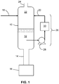
- FIG. 1 schematically shows a flash separator vessel used in a process for removing solid matter from the lower portion of a vessel that contains process liquid and unwanted solid matter and for removing MEG and water in an overhead.
- the method relates to a process where a hydrocarbon stream (or other non-volatile fluid) is employed to provide the heating duty to vaporize the MEG and water components of the feed. It has been discovered that MEG degradation is not instantaneous, and it has been further discovered that a flash separator vessel can be operated at higher pressures without any significant observed increase in MEG degradation products provided that the residence time of the MEG in the flash separator vessel is kept to a minimum. Tests have been carried out at atmospheric pressure, and higher pressure operation in principle should also be achievable.
- the process involves a MEG/water incoming stream entering a flash separator vessel where the MEG and water vaporizes rapidly and completely at temperatures higher than 150°C and at atmospheric pressure and above without any MEG/water inventory remaining in the device which could be exposed to the high temperature for a prolonged period.
- the temperature of the flash separator is in the range of 110 °C to 250 °C alternatively about or above 120°C independently to 250°C; in another non-limiting embodiment above 150°C independently to about 220°C; alternatively from above 165°C independently to about 220°C.
- independently is used herein with respect to a range, it means that any lower threshold may be combined with any upper threshold to give a suitable alternative range.
- the optimum temperature range is dependent on the composition of the feed input and on the operating pressure. Higher MEG content necessitates higher temperatures.
- the recycle heater outlet temperature, and thus the recycle heater differential temperature may be increased. This may give a further advantage of reducing the recycle flow rate thereby permitting smaller pumps and smaller diameter pipework.
- the residence time of the MEG and water ranges from about 1 second independently to about 10 minutes, alternatively from about 10 seconds independently to about 5 minutes, and in a different non-limiting embodiment, from about 20 seconds independently to about 1 minute.
- the shorter the residence time the better, but there is a finite amount of time required to warm the feed to its bubble point, and then to vaporize it.
- Suitable heat transfer fluids include, but are not necessarily limited to, aromatic hydrocarbons, alcohols, glycols, amines, silicone-based liquids, and mixtures thereof where these heat transfer fluids are not miscible with MEG.
- a suitable mixture of synthetic aromatic hydrocarbons is THERMINOL® ADX-10 heat transfer fluid available from Solutia Inc. Paraffinic hydrocarbon mixtures such as PARATHERM HE® and XCELTHERM® 600 can also be employed as the heat transfer fluid.
- Suitable silicone-based liquids include, but are not necessarily limited to, DURATHERM S, and the like.
- Salts that may contaminate the feed stream include, but are not necessarily limited to sodium chloride (NaCI), calcium chloride (CaCl 2 ), other chlorides, oxides, sulfates, acetates, nitrates, phosphates, bicarbonates and carbonates of sodium, potassium, calcium, magnesium, iron, copper, lead, barium, strontium, and the like, and combinations thereof.
- the feed stream may also contain a number of optional flow assurance chemicals such as scale inhibitors, corrosion inhibitors, wax inhibitors and oxygen scavengers
- the lower portion of a flash separator vessel 10 contains a mixture including process liquid 12 (i.e. the heat transfer fluid) that is substantially immiscible with water and undissolved solid matter or salt in particulate form.
- process liquid 12 i.e. the heat transfer fluid
- the undissolved solids may be removed from the process by a variety of technologies including, but not necessarily limited to, a conveying means such as a downcomer pipe 14 which is connected proximate the base of the vessel 10 to a solids collection tank 16. Removal of the solids from the process may be achieved employing one of a variety of commercially available solids-liquids separation processes such as settling tanks (as shown in Figure 1 ) or centrifuges.
- the feed stream 18 is a free flowing mixture including two or more miscible liquids (e.g. MEG and water) and dissolved solids (e.g. sodium chloride, magnesium chloride, calcium chloride from the gas production well and flow assurance chemicals added to the MEG-water solution to minimize pipe scaling and pipeline corrosion).
- miscible liquids e.g. MEG and water
- dissolved solids e.g. sodium chloride, magnesium chloride, calcium chloride from the gas production well and flow assurance chemicals added to the MEG-water solution to minimize pipe scaling and pipeline corrosion.
- examples of such mixtures include glycol/- water and amine/water that are contaminated with dissolved salts, corrosion products and/or other unwanted solids.
- the present process may be termed a "Flash-on-Oil” process (FoA). It is true that for FoO as well as for conventional MEG processes that one or more of the liquid component(s) boils at a significantly higher temperature than the other liquid components, but the present FoO process is operated such that, regardless of the differing boiling points, both (or all) of the components of the feed are fully vaporized. This is not the case in the conventional system where there is an equilibrium between the incoming MEG-water and the Recycle MEG such that a substantial inventory of MEG remains within the vessel. If the FoO process is properly optimized, then the quantity of MEG (water) present in the liquid phase in the vessel will be small.
- the feed stream 18 enters the flash separator vessel 10 and mixes with a larger and hotter stream of recycle liquor 20 that has also entered the separation vessel 10.
- the recycle liquor 20 in one non-limiting embodiment immediately heats the feed stream 18 and thereby causes the volatile components in the feed stream 18 to boil rapidly or flash.
- the feed stream 18 and recycle liquor 20 may be mixed upstream (not shown) of the separator vessel 10 and the commingled streams injected into the separation vessel 10.
- the vapor 22 generated by the flashing feed stream flows out of the separation vessel through the outlet channel 24.
- This vapor contains essentially no solids unless there is significant carryover of small particles or liquid droplets into the vapour.
- the vapor is MEG and water.
- Solids and unvaporised liquid collect in liquid pool 12 in the lower half of the separation vessel 10.
- the flash vaporisation that has occurred ensures that the liquid pool is composed mainly of the higher boiling point liquid (i.e. the heat transfer fluid) and solids.
- a recycle liquor 20, is drawn from the liquid pool and enters the recycle circuit 26 where it is pumped by the recycle pump 28, heated by the recycle heater 30 and mixed with the feed stream 18 as described above.
- An objective of the process herein is to minimize or prevent any MEG accumulation in the loop. This may be achieved by operating at a suitable temperature-pressure-residence time.
- the method employs short residence time for the MEG molecules in the Flash Vaporization zone in order to minimize thermal and oxidative-thermal degradation of the MEG molecules to organic acids and other species.
- Employing short residence times allows operating pressures at or close to ambient (atmospheric) to be employed.
- the temperature-pressure regime employed in the method is such that complete vaporization of the MEG and water components of the incoming feed stream is achieved.
- the MEG-water-salt composition, heat transfer fluids, pressures, temperatures, residence times, and/or flow rates may be changed or optimized from that illustrated and described, and even though certain additional features are not specifically identified or tried in a particular system, method or apparatus described herein, they would be anticipated to be within the scope of this disclosure. For instance, the parameters, compositions and treatments any of the described components and equipment would be expected to find utility and be encompassed by the appended claims.
Landscapes
- Chemical & Material Sciences (AREA)
- Organic Chemistry (AREA)
- Chemical Kinetics & Catalysis (AREA)
- Organic Low-Molecular-Weight Compounds And Preparation Thereof (AREA)
- Vaporization, Distillation, Condensation, Sublimation, And Cold Traps (AREA)
- Degasification And Air Bubble Elimination (AREA)
- Extraction Or Liquid Replacement (AREA)
Description
- This invention relates generally to a process for reclaiming monoethylene glycol (MEG) from a water miscible liquid, and more particularly relates to methods for reclaiming MEG with a heat transfer fluid at elevated temperatures and at higher pressures than are conventionally employed.
- In conventional MEG reclamation processes, which involve the removal of a salt from a MEG-water solution, a MEG-water-salt stream is contacted with a recycle stream of salt-saturated MEG operating at a temperature above the dew point of the incoming feed such that the volatile components of the feed are fully vaporized and the dissolved salt components of the feed are precipitated and removed from the heat transfer fluid. The recycle MEG stream thus acts as a heat transfer fluid. A hydrocarbon stream (or other non-volatile fluid) may also be employed as the recycle stream.
- Conventional MEG reclamation processes include, but are not necessarily limited to, those described in
U.S. Patent No. 6,685,802 ("the '802 patent") the process ofU.S. Patent No. 5,993,608 , ("the '608 patent"), the process ofUS Patent No. 6,340,373 ("the '373 patent"). - As noted, these processes involve the removal of salt from glycol that is used for dehydrating natural gas and for preventing hydrate formation in oil and gas production facilities. And as mentioned, the demineralization is typically done by a flash vaporization process in which a heated recycle liquid provides heat to vaporise an aqueous stream of glycol while collecting precipitated salt and other solid material in a liquid residue that can then be removed from the process. The processes described in the '802, '608, and '373 patents each include a flash vaporisation process similar to the above and such flash vaporisation processes have been or are being applied in the oil and gas industry to remove unwanted salt from glycol.
- The temperature above which MEG degrades significantly is widely accepted to be approximately 165°C. As a result, the flash vaporization process is carried out at sub-atmospheric pressures (0.1-0.3 barA; 0.01-0.03 MPa) in order to achieve complete vaporization of the MEG and water components at temperatures well below the accepted degradation temperature of 165°C. The recycle heater outlet temperature in conventional flash separators is typically limited to an upper value of 150°C as a consequence of the concern regarding MEG degradation.
- Conventional MEG reclamation processes employ a large recirculating inventory of concentrated MEG which is employed to provide the heating duty, as exemplified in
U.S. Pat. No. 8,728,321 . This recirculating MEG has a very long residence time in the MEG Reclamation system (in the order of several months to several years at the elevated temperatures required for complete vaporization. - The long residence time for the recirculating, salt-saturated, MEG stream (conventionally referred to as recycle MEG) makes the degradation process an issue. As a consequence of this long residence time, operation at reduced pressure has been conventionally deemed essential in order to prevent significant MEG degradation with consequential reduction in pH in the system through degradation of the MEG to formic acid, acetic acid, glycolic acid, and other carboxylic acids. The reduction in pH leads, potentially, to increased corrosion rates. Under such circumstances, in order to maintain an operable system, it is necessary to periodically blowdown and dispose of the degraded MEG from the system resulting in significant MEG losses and potential environmental impact from handling this waste product. Cost of disposal and replacement of MEG can be significant.
-
US 2011/094771 describes a process treating certain water miscible fluids including those used for oil and gas processing such as glycols, as well as automobile and aircraft fluids, that have become contaminated with dissolved and/or suspended solid matter.WO 2001/073204 describes a process for the regeneration of glycol from a mixture comprising glycol, water and salts, the salts comprising carbonate and/or bicarbonate ions. The mixture is flash distilled to obtain a salt- free solution of glycol and water. This solution is condensed and distilled to obtain glycol with reduced water content. The salts are concentrated in the vacuum boiler and removed from a substream taken out of a return circuit to the vacuum boiler. The process further comprises adding an acid prior to the evaporation and removing CO2 from the mixture in the evaporation. - It would thus be desirable if an improved process for reclaiming MEG were discovered which minimized or avoided one or more of these problems.
- The present invention resides in a process to reclaim monoethylene glycol (MEG) as defined in the appended claims.
-
FIG. 1 schematically shows a flash separator vessel used in a process for removing solid matter from the lower portion of a vessel that contains process liquid and unwanted solid matter and for removing MEG and water in an overhead. - It will be appreciated that the Figure is a schematic illustration that is not to scale or proportion, and, as such, some of the important parts of the invention may be exaggerated for illustration.
- The method relates to a process where a hydrocarbon stream (or other non-volatile fluid) is employed to provide the heating duty to vaporize the MEG and water components of the feed. It has been discovered that MEG degradation is not instantaneous, and it has been further discovered that a flash separator vessel can be operated at higher pressures without any significant observed increase in MEG degradation products provided that the residence time of the MEG in the flash separator vessel is kept to a minimum. Tests have been carried out at atmospheric pressure, and higher pressure operation in principle should also be achievable.
- This finding allows the flash separator vessel to operate at pressures above the currently recognized range of 0.1 to 0.3 barA (0.01 to 0.03 MPa); alternatively where the pressure is atmospheric and above; and in a different non-limiting embodiment where the pressure is from about atmospheric plus 5 psi (1.34 barA), and therefore at temperatures significantly higher than the previously recognized limit of 165°C. The benefits of operating at atmospheric pressure and above include, but are not necessarily limited to:
- 1) Reduced equipment size due to reduced vapor phase velocity at higher pressure. The flash separator vapors can be discharged to the site flare system without the requirements for a vacuum system.
- 2) The potential to eliminate the vacuum system which not only saves cost and complexity of the equipment.
- 3) Reduced potential for oxygen ingress, another cause of MEG degradation.
- In more detail, the process involves a MEG/water incoming stream entering a flash separator vessel where the MEG and water vaporizes rapidly and completely at temperatures higher than 150°C and at atmospheric pressure and above without any MEG/water inventory remaining in the device which could be exposed to the high temperature for a prolonged period. The temperature of the flash separator is in the range of 110 °C to 250 °C alternatively about or above 120°C independently to 250°C; in another non-limiting embodiment above 150°C independently to about 220°C; alternatively from above 165°C independently to about 220°C. When term "independently" is used herein with respect to a range, it means that any lower threshold may be combined with any upper threshold to give a suitable alternative range. The optimum temperature range is dependent on the composition of the feed input and on the operating pressure. Higher MEG content necessitates higher temperatures. In one non-limiting embodiment, if the liquid pool equilibrium temperature is maintained at about 220°C, but there is a differential temperature across the recycle heat exchanger, and if an elevated temperature is required because the MEG residence time is kept to a minimum, then the recycle heater outlet temperature, and thus the recycle heater differential temperature, may be increased. This may give a further advantage of reducing the recycle flow rate thereby permitting smaller pumps and smaller diameter pipework.
- The residence time of the MEG and water ranges from about 1 second independently to about 10 minutes, alternatively from about 10 seconds independently to about 5 minutes, and in a different non-limiting embodiment, from about 20 seconds independently to about 1 minute. In general, the shorter the residence time, the better, but there is a finite amount of time required to warm the feed to its bubble point, and then to vaporize it.
- Suitable heat transfer fluids include, but are not necessarily limited to, aromatic hydrocarbons, alcohols, glycols, amines, silicone-based liquids, and mixtures thereof where these heat transfer fluids are not miscible with MEG. In one non-limiting example, a suitable mixture of synthetic aromatic hydrocarbons is THERMINOL® ADX-10 heat transfer fluid available from Solutia Inc. Paraffinic hydrocarbon mixtures such as PARATHERM HE® and XCELTHERM® 600 can also be employed as the heat transfer fluid. Suitable silicone-based liquids include, but are not necessarily limited to, DURATHERM S, and the like.
- Salts that may contaminate the feed stream include, but are not necessarily limited to sodium chloride (NaCI), calcium chloride (CaCl2), other chlorides, oxides, sulfates, acetates, nitrates, phosphates, bicarbonates and carbonates of sodium, potassium, calcium, magnesium, iron, copper, lead, barium, strontium, and the like, and combinations thereof. In addition, the feed stream may also contain a number of optional flow assurance chemicals such as scale inhibitors, corrosion inhibitors, wax inhibitors and oxygen scavengers
- As shown in
FIG. 1 , the lower portion of aflash separator vessel 10 contains a mixture including process liquid 12 (i.e. the heat transfer fluid) that is substantially immiscible with water and undissolved solid matter or salt in particulate form. The undissolved solids may be removed from the process by a variety of technologies including, but not necessarily limited to, a conveying means such as adowncomer pipe 14 which is connected proximate the base of thevessel 10 to asolids collection tank 16. Removal of the solids from the process may be achieved employing one of a variety of commercially available solids-liquids separation processes such as settling tanks (as shown inFigure 1 ) or centrifuges. Thefeed stream 18 is a free flowing mixture including two or more miscible liquids (e.g. MEG and water) and dissolved solids (e.g. sodium chloride, magnesium chloride, calcium chloride from the gas production well and flow assurance chemicals added to the MEG-water solution to minimize pipe scaling and pipeline corrosion). Examples of such mixtures include glycol/- water and amine/water that are contaminated with dissolved salts, corrosion products and/or other unwanted solids. - The present process may be termed a "Flash-on-Oil" process (FoA). It is true that for FoO as well as for conventional MEG processes that one or more of the liquid component(s) boils at a significantly higher temperature than the other liquid components, but the present FoO process is operated such that, regardless of the differing boiling points, both (or all) of the components of the feed are fully vaporized. This is not the case in the conventional system where there is an equilibrium between the incoming MEG-water and the Recycle MEG such that a substantial inventory of MEG remains within the vessel. If the FoO process is properly optimized, then the quantity of MEG (water) present in the liquid phase in the vessel will be small.
- The
feed stream 18 enters theflash separator vessel 10 and mixes with a larger and hotter stream ofrecycle liquor 20 that has also entered theseparation vessel 10. Therecycle liquor 20 in one non-limiting embodiment immediately heats thefeed stream 18 and thereby causes the volatile components in thefeed stream 18 to boil rapidly or flash. - Alternatively, the
feed stream 18 and recycleliquor 20 may be mixed upstream (not shown) of theseparator vessel 10 and the commingled streams injected into theseparation vessel 10. - The
vapor 22 generated by the flashing feed stream flows out of the separation vessel through theoutlet channel 24. This vapor contains essentially no solids unless there is significant carryover of small particles or liquid droplets into the vapour. In one non-limiting embodiment the vapor is MEG and water. - Solids and unvaporised liquid collect in
liquid pool 12 in the lower half of theseparation vessel 10. The flash vaporisation that has occurred ensures that the liquid pool is composed mainly of the higher boiling point liquid (i.e. the heat transfer fluid) and solids. Arecycle liquor 20, is drawn from the liquid pool and enters therecycle circuit 26 where it is pumped by therecycle pump 28, heated by therecycle heater 30 and mixed with thefeed stream 18 as described above. An objective of the process herein is to minimize or prevent any MEG accumulation in the loop. This may be achieved by operating at a suitable temperature-pressure-residence time. - The method employs short residence time for the MEG molecules in the Flash Vaporization zone in order to minimize thermal and oxidative-thermal degradation of the MEG molecules to organic acids and other species. Employing short residence times allows operating pressures at or close to ambient (atmospheric) to be employed. The temperature-pressure regime employed in the method is such that complete vaporization of the MEG and water components of the incoming feed stream is achieved.
- There are significant and substantial benefits in operating at atmospheric pressure and above rather than the 0.1-0.3 barA (0.01-0.03 MPa) conventionally employed for the flash vaporization process. These are exemplified below:
- 1) Degradation of MEG and Corrosion: In conventional MEG reclamation methods operated under partial vacuum, there is increased potential for ingress of air into the flash separator vessel through leakage at the flanges and fittings. The oxygen present in the incoming air can result in increased degradation of the MEG to organic acids which in turn can result in increased corrosion of pipework. Operating at atmospheric pressure or above will significantly reduce potential for air ingress. In one non-limiting embodiment the flash separator vessel will be operated at a pressure slightly above atmospheric pressure. In another non-restrictive version the actual operating pressure will be determined by equipment and pipework downstream of the vessel, but the operating pressure may likely be around 5 psiG (20 psiA, 1.35 bar A).
- 2) Complex Vacuum System: Operation at the reduced pressure of conventional MEG reclamation methods requires a vacuum system. The vacuum system can be complex and adds additional weight, space requirements and utility (electrical and cooling medium) demand on the MEG package. Space and weight restrictions are important particularly for off-shore applications where space and weight are at a premium. Operation of the Flash Separator at atmospheric pressure as in the present method would remove the requirement for a vacuum package.
- 3) Large Diameter Vessels and Pipework: Operation at low pressure (0.1-0.3 barA (0.01-0.03 MPa)) results in the production of large volumes of low density vapor (MEG-water) from the flash vaporization process. This large volumetric flow requires a large flash separator vessel, large diameter pipework and larger equipment (typically condenser, knockout drum and distillation column) downstream of the Flash Separator vessel. In the present method, operating at atmospheric pressure will reduce the size of the Flash Separator vessel, pipework and downstream equipment treating the overhead vapors. Size (surface area) of condenser equipment in the Reclaimer section will also be reduced by operating at atmospheric pressure.
- In the foregoing specification, the disclosure has been described with reference to specific embodiments thereof, and is expected to be effective in providing methods and apparatus that improve the reclamation of MEG by allowing the flash separator to operate at atmospheric pressure and above even at atmospheric pressure, and therefore, at temperatures significantly higher than the conventionally recognized limit of 165°C. However, it will be evident that various modifications and changes may be made thereto without departing from the broader scope of the disclosure as set forth in the appended claims. Accordingly, the specification is to be regarded in an illustrative rather than a restrictive sense. For example, the MEG-water-salt composition, heat transfer fluids, pressures, temperatures, residence times, and/or flow rates may be changed or optimized from that illustrated and described, and even though certain additional features are not specifically identified or tried in a particular system, method or apparatus described herein, they would be anticipated to be within the scope of this disclosure. For instance, the parameters, compositions and treatments any of the described components and equipment would be expected to find utility and be encompassed by the appended claims.
- The words "comprising" and "comprises" as used throughout the claims are to be interpreted as "including but not limited to".
Claims (4)
- A process to reclaim monoethylene glycol (MEG), the process comprising:contacting a stream comprising MEG, water, and at least one salt with a
heat transfer fluid;flash separating the MEG and water from the stream in a flash separator vessel where:the pressure is where the pressure is atmospheric and above;the temperature is in the range of 110°C to 250°C; andthe residence time of the MEG and water ranges from 1 second to 10 minutes; andremoving the MEG and water in an overhead of the flash separator vessel; andremoving the at least one salt from the flash separator vessel. - The process of claim 1 where the temperature is above 165°C to 220°C.
- The process of claim 1 where the heat transfer fluid is selected from the group consisting of aromatic hydrocarbons, paraffinic hydrocarbons, alcohols, glycols, amines, silicone-based liquids and mixtures thereof.
- The process of any of claims 1, 2, or 3 wherein no vacuum system is used in the process.
Applications Claiming Priority (2)
| Application Number | Priority Date | Filing Date | Title |
|---|---|---|---|
| US14/800,876 US11524927B2 (en) | 2015-07-16 | 2015-07-16 | Short contact, elevated temperature MEG reclamation |
| PCT/US2016/040309 WO2017011195A1 (en) | 2015-07-16 | 2016-06-30 | Short contact, elevated temperature meg reclamation |
Publications (3)
| Publication Number | Publication Date |
|---|---|
| EP3322684A1 EP3322684A1 (en) | 2018-05-23 |
| EP3322684A4 EP3322684A4 (en) | 2019-02-27 |
| EP3322684B1 true EP3322684B1 (en) | 2020-07-08 |
Family
ID=57757359
Family Applications (1)
| Application Number | Title | Priority Date | Filing Date |
|---|---|---|---|
| EP16824883.9A Active EP3322684B1 (en) | 2015-07-16 | 2016-06-30 | Short contact, elevated temperature meg reclamation |
Country Status (9)
| Country | Link |
|---|---|
| US (2) | US11524927B2 (en) |
| EP (1) | EP3322684B1 (en) |
| CN (1) | CN107848923B (en) |
| AU (1) | AU2016292774B2 (en) |
| BR (1) | BR112018000918B1 (en) |
| CA (1) | CA2992562C (en) |
| MX (1) | MX2018000630A (en) |
| MY (1) | MY187069A (en) |
| WO (1) | WO2017011195A1 (en) |
Families Citing this family (6)
| Publication number | Priority date | Publication date | Assignee | Title |
|---|---|---|---|---|
| US10807017B2 (en) | 2018-12-20 | 2020-10-20 | Schlumberger Technology Corporation | Heating flash-on-oil vapor section |
| US10954179B1 (en) * | 2019-08-28 | 2021-03-23 | Cameron International Corporation | Method and apparatus for filtering heat transfer fluid from a monoethylene glycol stream |
| CN114746387A (en) | 2019-12-02 | 2022-07-12 | 斯伦贝谢技术有限公司 | Reducing energy consumption in MEG regeneration |
| EP4196242A4 (en) * | 2020-08-14 | 2024-12-04 | Craig Nazzer | Method for separating water and contaminants from valuable or harmful liquids |
| CN116615273A (en) * | 2020-08-14 | 2023-08-18 | 克雷格·纳泽尔 | Method for separating water and contaminants from valuable or hazardous liquids |
| US11752447B2 (en) * | 2021-05-28 | 2023-09-12 | Prime Services Trustee Limited | Methods for separating water and contaminants from valuable or harmful process liquids |
Family Cites Families (11)
| Publication number | Priority date | Publication date | Assignee | Title |
|---|---|---|---|---|
| NO307503B1 (en) | 1997-03-05 | 2000-04-17 | Kvaerner Process Systems As | Method and apparatus for processing and processing a fluid |
| US5993608A (en) | 1997-04-25 | 1999-11-30 | Canadian Chemical Reclaiming Ltd. | Process for recovering processing liquids |
| US6023003A (en) | 1998-01-13 | 2000-02-08 | Reading & Bates Development Co. | Process and system for recovering glycol from glycol/brine streams |
| NZ332331A (en) | 1998-10-15 | 2000-03-27 | Craig Nazzer | Continuous process for removing solids from miscible liquid mixture; lower boiling point liquid(s) removed by flashing or boiling |
| AU2005235496B2 (en) | 2004-04-21 | 2010-05-20 | Prime Services Trustee Limited | Process for separating one or more solids from water miscible fluids and an apparatus therefor |
| NO20056113L (en) | 2005-12-21 | 2007-06-22 | Statoil Asa | Glycol Regeneration Process and Plant |
| KR101433970B1 (en) * | 2006-06-13 | 2014-08-25 | 셀 인터나쵸나아레 레사아치 마아츠샤피 비이부이 | Glycol separation and purification |
| BRPI0814016A2 (en) | 2007-07-30 | 2015-02-03 | Cameron Int Corp | REMOVAL OF SOLIDS IN REPAIR OF MONOETHYLENEGLYCOL |
| TWI423946B (en) | 2007-11-14 | 2014-01-21 | Shell Int Research | Process for the preparation of alkylene glycol |
| WO2009154477A1 (en) | 2008-06-15 | 2009-12-23 | Craig Nazzer | Process for separating solids from valuable or harmful liquids by vaporisation |
| FR3013710B1 (en) | 2013-11-22 | 2016-01-01 | Prosernat | FLEXIBLE PROCESS FOR THE TREATMENT OF SOLVENT, SUCH AS MONOETHYLENE GLYCOL, FOR THE EXTRACTION OF NATURAL GAS |
-
2015
- 2015-07-16 US US14/800,876 patent/US11524927B2/en active Active
-
2016
- 2016-06-30 CA CA2992562A patent/CA2992562C/en active Active
- 2016-06-30 EP EP16824883.9A patent/EP3322684B1/en active Active
- 2016-06-30 WO PCT/US2016/040309 patent/WO2017011195A1/en not_active Ceased
- 2016-06-30 BR BR112018000918-0A patent/BR112018000918B1/en active IP Right Grant
- 2016-06-30 CN CN201680041881.9A patent/CN107848923B/en active Active
- 2016-06-30 MY MYPI2018000055A patent/MY187069A/en unknown
- 2016-06-30 MX MX2018000630A patent/MX2018000630A/en unknown
- 2016-06-30 AU AU2016292774A patent/AU2016292774B2/en active Active
-
2019
- 2019-11-11 US US16/680,176 patent/US20200079713A1/en not_active Abandoned
Non-Patent Citations (1)
| Title |
|---|
| None * |
Also Published As
| Publication number | Publication date |
|---|---|
| BR112018000918A2 (en) | 2018-09-11 |
| MX2018000630A (en) | 2018-09-06 |
| US11524927B2 (en) | 2022-12-13 |
| WO2017011195A1 (en) | 2017-01-19 |
| MY187069A (en) | 2021-08-28 |
| BR112018000918B1 (en) | 2021-08-03 |
| AU2016292774B2 (en) | 2020-09-03 |
| US20170015613A1 (en) | 2017-01-19 |
| AU2016292774A1 (en) | 2018-02-01 |
| EP3322684A4 (en) | 2019-02-27 |
| CN107848923A (en) | 2018-03-27 |
| CA2992562A1 (en) | 2017-01-19 |
| CA2992562C (en) | 2024-09-10 |
| EP3322684A1 (en) | 2018-05-23 |
| CN107848923B (en) | 2025-12-19 |
| US20200079713A1 (en) | 2020-03-12 |
Similar Documents
| Publication | Publication Date | Title |
|---|---|---|
| US20200079713A1 (en) | Short contact, elevated temperature meg reclamation | |
| CA2727906C (en) | Process for separating solids from valuable or harmful liquids by vaporisation | |
| US9090813B2 (en) | Process for hydrate inhibitor regeneration | |
| AU2013279331B2 (en) | Method and apparatus for circulating a glycol stream, and method of producing a natural gas product stream | |
| RU2564034C2 (en) | Method and device for separation of multi-charge cations from monoethyleneglycol | |
| WO2010080038A1 (en) | Method for regeneration and reclamation of mono ethylene glycol using a vacuum slip stream | |
| KR101795003B1 (en) | Device for regenerating mono-ethylene glycol and method for regenerating mono-ethylene glycol | |
| WO2018115442A1 (en) | Hydrate inhibitor recovery system | |
| KR102439757B1 (en) | Process for recovering a treatment liquor from a stream containing alkaline earth metal salts | |
| US11752447B2 (en) | Methods for separating water and contaminants from valuable or harmful process liquids | |
| CN116615273A (en) | Method for separating water and contaminants from valuable or hazardous liquids | |
| JP2020185502A (en) | Production method for recycled organic solvent and device for reducing impurity amount in impurity-including organic solvent | |
| HK1235730B (en) | Process for recovering processing liquids from streams containing alkaline earth metal salts | |
| AU4270300A (en) | Method of removing water and contaminants from crude oil containing same |
Legal Events
| Date | Code | Title | Description |
|---|---|---|---|
| STAA | Information on the status of an ep patent application or granted ep patent |
Free format text: STATUS: THE INTERNATIONAL PUBLICATION HAS BEEN MADE |
|
| PUAI | Public reference made under article 153(3) epc to a published international application that has entered the european phase |
Free format text: ORIGINAL CODE: 0009012 |
|
| STAA | Information on the status of an ep patent application or granted ep patent |
Free format text: STATUS: REQUEST FOR EXAMINATION WAS MADE |
|
| 17P | Request for examination filed |
Effective date: 20180215 |
|
| AK | Designated contracting states |
Kind code of ref document: A1 Designated state(s): AL AT BE BG CH CY CZ DE DK EE ES FI FR GB GR HR HU IE IS IT LI LT LU LV MC MK MT NL NO PL PT RO RS SE SI SK SM TR |
|
| AX | Request for extension of the european patent |
Extension state: BA ME |
|
| DAV | Request for validation of the european patent (deleted) | ||
| DAX | Request for extension of the european patent (deleted) | ||
| A4 | Supplementary search report drawn up and despatched |
Effective date: 20190125 |
|
| RIC1 | Information provided on ipc code assigned before grant |
Ipc: B01D 3/00 20060101ALI20190121BHEP Ipc: C07C 51/44 20060101ALI20190121BHEP Ipc: C07C 31/20 20060101ALI20190121BHEP Ipc: C07C 29/80 20060101AFI20190121BHEP Ipc: B01D 3/06 20060101ALI20190121BHEP |
|
| GRAP | Despatch of communication of intention to grant a patent |
Free format text: ORIGINAL CODE: EPIDOSNIGR1 |
|
| STAA | Information on the status of an ep patent application or granted ep patent |
Free format text: STATUS: GRANT OF PATENT IS INTENDED |
|
| RIC1 | Information provided on ipc code assigned before grant |
Ipc: B01D 3/06 20060101ALI20200114BHEP Ipc: C07C 29/80 20060101AFI20200114BHEP Ipc: C07C 51/44 20060101ALI20200114BHEP Ipc: C07C 31/20 20060101ALI20200114BHEP Ipc: B01D 3/00 20060101ALI20200114BHEP |
|
| INTG | Intention to grant announced |
Effective date: 20200205 |
|
| GRAS | Grant fee paid |
Free format text: ORIGINAL CODE: EPIDOSNIGR3 |
|
| GRAA | (expected) grant |
Free format text: ORIGINAL CODE: 0009210 |
|
| STAA | Information on the status of an ep patent application or granted ep patent |
Free format text: STATUS: THE PATENT HAS BEEN GRANTED |
|
| AK | Designated contracting states |
Kind code of ref document: B1 Designated state(s): AL AT BE BG CH CY CZ DE DK EE ES FI FR GB GR HR HU IE IS IT LI LT LU LV MC MK MT NL NO PL PT RO RS SE SI SK SM TR |
|
| REG | Reference to a national code |
Ref country code: CH Ref legal event code: EP Ref country code: AT Ref legal event code: REF Ref document number: 1288297 Country of ref document: AT Kind code of ref document: T Effective date: 20200715 |
|
| REG | Reference to a national code |
Ref country code: DE Ref legal event code: R096 Ref document number: 602016039689 Country of ref document: DE |
|
| REG | Reference to a national code |
Ref country code: IE Ref legal event code: FG4D |
|
| REG | Reference to a national code |
Ref country code: NL Ref legal event code: FP |
|
| REG | Reference to a national code |
Ref country code: LT Ref legal event code: MG4D |
|
| REG | Reference to a national code |
Ref country code: NO Ref legal event code: T2 Effective date: 20200708 |
|
| RAP2 | Party data changed (patent owner data changed or rights of a patent transferred) |
Owner name: CAMERON TECHNOLOGIES LIMITED |
|
| REG | Reference to a national code |
Ref country code: AT Ref legal event code: MK05 Ref document number: 1288297 Country of ref document: AT Kind code of ref document: T Effective date: 20200708 |
|
| PG25 | Lapsed in a contracting state [announced via postgrant information from national office to epo] |
Ref country code: HR Free format text: LAPSE BECAUSE OF FAILURE TO SUBMIT A TRANSLATION OF THE DESCRIPTION OR TO PAY THE FEE WITHIN THE PRESCRIBED TIME-LIMIT Effective date: 20200708 Ref country code: SE Free format text: LAPSE BECAUSE OF FAILURE TO SUBMIT A TRANSLATION OF THE DESCRIPTION OR TO PAY THE FEE WITHIN THE PRESCRIBED TIME-LIMIT Effective date: 20200708 Ref country code: AT Free format text: LAPSE BECAUSE OF FAILURE TO SUBMIT A TRANSLATION OF THE DESCRIPTION OR TO PAY THE FEE WITHIN THE PRESCRIBED TIME-LIMIT Effective date: 20200708 Ref country code: FI Free format text: LAPSE BECAUSE OF FAILURE TO SUBMIT A TRANSLATION OF THE DESCRIPTION OR TO PAY THE FEE WITHIN THE PRESCRIBED TIME-LIMIT Effective date: 20200708 Ref country code: GR Free format text: LAPSE BECAUSE OF FAILURE TO SUBMIT A TRANSLATION OF THE DESCRIPTION OR TO PAY THE FEE WITHIN THE PRESCRIBED TIME-LIMIT Effective date: 20201009 Ref country code: BG Free format text: LAPSE BECAUSE OF FAILURE TO SUBMIT A TRANSLATION OF THE DESCRIPTION OR TO PAY THE FEE WITHIN THE PRESCRIBED TIME-LIMIT Effective date: 20201008 Ref country code: PT Free format text: LAPSE BECAUSE OF FAILURE TO SUBMIT A TRANSLATION OF THE DESCRIPTION OR TO PAY THE FEE WITHIN THE PRESCRIBED TIME-LIMIT Effective date: 20201109 Ref country code: LT Free format text: LAPSE BECAUSE OF FAILURE TO SUBMIT A TRANSLATION OF THE DESCRIPTION OR TO PAY THE FEE WITHIN THE PRESCRIBED TIME-LIMIT Effective date: 20200708 Ref country code: ES Free format text: LAPSE BECAUSE OF FAILURE TO SUBMIT A TRANSLATION OF THE DESCRIPTION OR TO PAY THE FEE WITHIN THE PRESCRIBED TIME-LIMIT Effective date: 20200708 |
|
| PG25 | Lapsed in a contracting state [announced via postgrant information from national office to epo] |
Ref country code: PL Free format text: LAPSE BECAUSE OF FAILURE TO SUBMIT A TRANSLATION OF THE DESCRIPTION OR TO PAY THE FEE WITHIN THE PRESCRIBED TIME-LIMIT Effective date: 20200708 Ref country code: RS Free format text: LAPSE BECAUSE OF FAILURE TO SUBMIT A TRANSLATION OF THE DESCRIPTION OR TO PAY THE FEE WITHIN THE PRESCRIBED TIME-LIMIT Effective date: 20200708 Ref country code: LV Free format text: LAPSE BECAUSE OF FAILURE TO SUBMIT A TRANSLATION OF THE DESCRIPTION OR TO PAY THE FEE WITHIN THE PRESCRIBED TIME-LIMIT Effective date: 20200708 Ref country code: IS Free format text: LAPSE BECAUSE OF FAILURE TO SUBMIT A TRANSLATION OF THE DESCRIPTION OR TO PAY THE FEE WITHIN THE PRESCRIBED TIME-LIMIT Effective date: 20201108 |
|
| REG | Reference to a national code |
Ref country code: DE Ref legal event code: R097 Ref document number: 602016039689 Country of ref document: DE |
|
| PG25 | Lapsed in a contracting state [announced via postgrant information from national office to epo] |
Ref country code: EE Free format text: LAPSE BECAUSE OF FAILURE TO SUBMIT A TRANSLATION OF THE DESCRIPTION OR TO PAY THE FEE WITHIN THE PRESCRIBED TIME-LIMIT Effective date: 20200708 Ref country code: SM Free format text: LAPSE BECAUSE OF FAILURE TO SUBMIT A TRANSLATION OF THE DESCRIPTION OR TO PAY THE FEE WITHIN THE PRESCRIBED TIME-LIMIT Effective date: 20200708 Ref country code: DK Free format text: LAPSE BECAUSE OF FAILURE TO SUBMIT A TRANSLATION OF THE DESCRIPTION OR TO PAY THE FEE WITHIN THE PRESCRIBED TIME-LIMIT Effective date: 20200708 Ref country code: CZ Free format text: LAPSE BECAUSE OF FAILURE TO SUBMIT A TRANSLATION OF THE DESCRIPTION OR TO PAY THE FEE WITHIN THE PRESCRIBED TIME-LIMIT Effective date: 20200708 Ref country code: RO Free format text: LAPSE BECAUSE OF FAILURE TO SUBMIT A TRANSLATION OF THE DESCRIPTION OR TO PAY THE FEE WITHIN THE PRESCRIBED TIME-LIMIT Effective date: 20200708 |
|
| PLBE | No opposition filed within time limit |
Free format text: ORIGINAL CODE: 0009261 |
|
| STAA | Information on the status of an ep patent application or granted ep patent |
Free format text: STATUS: NO OPPOSITION FILED WITHIN TIME LIMIT |
|
| PG25 | Lapsed in a contracting state [announced via postgrant information from national office to epo] |
Ref country code: AL Free format text: LAPSE BECAUSE OF FAILURE TO SUBMIT A TRANSLATION OF THE DESCRIPTION OR TO PAY THE FEE WITHIN THE PRESCRIBED TIME-LIMIT Effective date: 20200708 |
|
| 26N | No opposition filed |
Effective date: 20210409 |
|
| PG25 | Lapsed in a contracting state [announced via postgrant information from national office to epo] |
Ref country code: SK Free format text: LAPSE BECAUSE OF FAILURE TO SUBMIT A TRANSLATION OF THE DESCRIPTION OR TO PAY THE FEE WITHIN THE PRESCRIBED TIME-LIMIT Effective date: 20200708 |
|
| PG25 | Lapsed in a contracting state [announced via postgrant information from national office to epo] |
Ref country code: SI Free format text: LAPSE BECAUSE OF FAILURE TO SUBMIT A TRANSLATION OF THE DESCRIPTION OR TO PAY THE FEE WITHIN THE PRESCRIBED TIME-LIMIT Effective date: 20200708 |
|
| REG | Reference to a national code |
Ref country code: DE Ref legal event code: R119 Ref document number: 602016039689 Country of ref document: DE |
|
| PG25 | Lapsed in a contracting state [announced via postgrant information from national office to epo] |
Ref country code: MC Free format text: LAPSE BECAUSE OF FAILURE TO SUBMIT A TRANSLATION OF THE DESCRIPTION OR TO PAY THE FEE WITHIN THE PRESCRIBED TIME-LIMIT Effective date: 20200708 |
|
| REG | Reference to a national code |
Ref country code: CH Ref legal event code: PL |
|
| REG | Reference to a national code |
Ref country code: BE Ref legal event code: MM Effective date: 20210630 |
|
| PG25 | Lapsed in a contracting state [announced via postgrant information from national office to epo] |
Ref country code: LU Free format text: LAPSE BECAUSE OF NON-PAYMENT OF DUE FEES Effective date: 20210630 |
|
| PG25 | Lapsed in a contracting state [announced via postgrant information from national office to epo] |
Ref country code: LI Free format text: LAPSE BECAUSE OF NON-PAYMENT OF DUE FEES Effective date: 20210630 Ref country code: IE Free format text: LAPSE BECAUSE OF NON-PAYMENT OF DUE FEES Effective date: 20210630 Ref country code: DE Free format text: LAPSE BECAUSE OF NON-PAYMENT OF DUE FEES Effective date: 20220101 Ref country code: CH Free format text: LAPSE BECAUSE OF NON-PAYMENT OF DUE FEES Effective date: 20210630 |
|
| REG | Reference to a national code |
Ref country code: NL Ref legal event code: PD Owner name: CAMERON TECHNOLOGIES LIMITED; NL Free format text: DETAILS ASSIGNMENT: CHANGE OF OWNER(S), ASSIGNMENT; FORMER OWNER NAME: CAMERON INTERNATIONAL CORPORATION Effective date: 20220415 |
|
| PG25 | Lapsed in a contracting state [announced via postgrant information from national office to epo] |
Ref country code: BE Free format text: LAPSE BECAUSE OF NON-PAYMENT OF DUE FEES Effective date: 20210630 |
|
| PG25 | Lapsed in a contracting state [announced via postgrant information from national office to epo] |
Ref country code: CY Free format text: LAPSE BECAUSE OF FAILURE TO SUBMIT A TRANSLATION OF THE DESCRIPTION OR TO PAY THE FEE WITHIN THE PRESCRIBED TIME-LIMIT Effective date: 20200708 |
|
| PG25 | Lapsed in a contracting state [announced via postgrant information from national office to epo] |
Ref country code: HU Free format text: LAPSE BECAUSE OF FAILURE TO SUBMIT A TRANSLATION OF THE DESCRIPTION OR TO PAY THE FEE WITHIN THE PRESCRIBED TIME-LIMIT; INVALID AB INITIO Effective date: 20160630 |
|
| P01 | Opt-out of the competence of the unified patent court (upc) registered |
Effective date: 20231208 |
|
| PG25 | Lapsed in a contracting state [announced via postgrant information from national office to epo] |
Ref country code: MK Free format text: LAPSE BECAUSE OF FAILURE TO SUBMIT A TRANSLATION OF THE DESCRIPTION OR TO PAY THE FEE WITHIN THE PRESCRIBED TIME-LIMIT Effective date: 20200708 |
|
| PG25 | Lapsed in a contracting state [announced via postgrant information from national office to epo] |
Ref country code: MT Free format text: LAPSE BECAUSE OF FAILURE TO SUBMIT A TRANSLATION OF THE DESCRIPTION OR TO PAY THE FEE WITHIN THE PRESCRIBED TIME-LIMIT Effective date: 20200708 |
|
| PGFP | Annual fee paid to national office [announced via postgrant information from national office to epo] |
Ref country code: NL Payment date: 20250516 Year of fee payment: 10 |
|
| PGFP | Annual fee paid to national office [announced via postgrant information from national office to epo] |
Ref country code: GB Payment date: 20250508 Year of fee payment: 10 |
|
| PGFP | Annual fee paid to national office [announced via postgrant information from national office to epo] |
Ref country code: NO Payment date: 20250610 Year of fee payment: 10 |
|
| PGFP | Annual fee paid to national office [announced via postgrant information from national office to epo] |
Ref country code: IT Payment date: 20250522 Year of fee payment: 10 |
|
| PGFP | Annual fee paid to national office [announced via postgrant information from national office to epo] |
Ref country code: FR Payment date: 20250508 Year of fee payment: 10 |
|
| PG25 | Lapsed in a contracting state [announced via postgrant information from national office to epo] |
Ref country code: TR Free format text: LAPSE BECAUSE OF FAILURE TO SUBMIT A TRANSLATION OF THE DESCRIPTION OR TO PAY THE FEE WITHIN THE PRESCRIBED TIME-LIMIT Effective date: 20200708 |