EP3322518B1 - A process to prepare shaped bodies - Google Patents
A process to prepare shaped bodies Download PDFInfo
- Publication number
- EP3322518B1 EP3322518B1 EP16760135.0A EP16760135A EP3322518B1 EP 3322518 B1 EP3322518 B1 EP 3322518B1 EP 16760135 A EP16760135 A EP 16760135A EP 3322518 B1 EP3322518 B1 EP 3322518B1
- Authority
- EP
- European Patent Office
- Prior art keywords
- resin
- lignin
- monolith
- particles
- carbonised
- Prior art date
- Legal status (The legal status is an assumption and is not a legal conclusion. Google has not performed a legal analysis and makes no representation as to the accuracy of the status listed.)
- Active
Links
Images









Classifications
-
- B—PERFORMING OPERATIONS; TRANSPORTING
- B01—PHYSICAL OR CHEMICAL PROCESSES OR APPARATUS IN GENERAL
- B01J—CHEMICAL OR PHYSICAL PROCESSES, e.g. CATALYSIS OR COLLOID CHEMISTRY; THEIR RELEVANT APPARATUS
- B01J20/00—Solid sorbent compositions or filter aid compositions; Sorbents for chromatography; Processes for preparing, regenerating or reactivating thereof
- B01J20/02—Solid sorbent compositions or filter aid compositions; Sorbents for chromatography; Processes for preparing, regenerating or reactivating thereof comprising inorganic material
- B01J20/20—Solid sorbent compositions or filter aid compositions; Sorbents for chromatography; Processes for preparing, regenerating or reactivating thereof comprising inorganic material comprising free carbon; comprising carbon obtained by carbonising processes
-
- A—HUMAN NECESSITIES
- A61—MEDICAL OR VETERINARY SCIENCE; HYGIENE
- A61M—DEVICES FOR INTRODUCING MEDIA INTO, OR ONTO, THE BODY; DEVICES FOR TRANSDUCING BODY MEDIA OR FOR TAKING MEDIA FROM THE BODY; DEVICES FOR PRODUCING OR ENDING SLEEP OR STUPOR
- A61M1/00—Suction or pumping devices for medical purposes; Devices for carrying-off, for treatment of, or for carrying-over, body-liquids; Drainage systems
- A61M1/34—Filtering material out of the blood by passing it through a membrane, i.e. hemofiltration or diafiltration
-
- A—HUMAN NECESSITIES
- A61—MEDICAL OR VETERINARY SCIENCE; HYGIENE
- A61M—DEVICES FOR INTRODUCING MEDIA INTO, OR ONTO, THE BODY; DEVICES FOR TRANSDUCING BODY MEDIA OR FOR TAKING MEDIA FROM THE BODY; DEVICES FOR PRODUCING OR ENDING SLEEP OR STUPOR
- A61M1/00—Suction or pumping devices for medical purposes; Devices for carrying-off, for treatment of, or for carrying-over, body-liquids; Drainage systems
- A61M1/34—Filtering material out of the blood by passing it through a membrane, i.e. hemofiltration or diafiltration
- A61M1/3472—Filtering material out of the blood by passing it through a membrane, i.e. hemofiltration or diafiltration with treatment of the filtrate
- A61M1/3486—Biological, chemical treatment, e.g. chemical precipitation; treatment by absorbents
-
- A—HUMAN NECESSITIES
- A61—MEDICAL OR VETERINARY SCIENCE; HYGIENE
- A61M—DEVICES FOR INTRODUCING MEDIA INTO, OR ONTO, THE BODY; DEVICES FOR TRANSDUCING BODY MEDIA OR FOR TAKING MEDIA FROM THE BODY; DEVICES FOR PRODUCING OR ENDING SLEEP OR STUPOR
- A61M1/00—Suction or pumping devices for medical purposes; Devices for carrying-off, for treatment of, or for carrying-over, body-liquids; Drainage systems
- A61M1/36—Other treatment of blood in a by-pass of the natural circulatory system, e.g. temperature adaptation, irradiation ; Extra-corporeal blood circuits
- A61M1/3679—Other treatment of blood in a by-pass of the natural circulatory system, e.g. temperature adaptation, irradiation ; Extra-corporeal blood circuits by absorption
-
- B—PERFORMING OPERATIONS; TRANSPORTING
- B01—PHYSICAL OR CHEMICAL PROCESSES OR APPARATUS IN GENERAL
- B01J—CHEMICAL OR PHYSICAL PROCESSES, e.g. CATALYSIS OR COLLOID CHEMISTRY; THEIR RELEVANT APPARATUS
- B01J20/00—Solid sorbent compositions or filter aid compositions; Sorbents for chromatography; Processes for preparing, regenerating or reactivating thereof
- B01J20/28—Solid sorbent compositions or filter aid compositions; Sorbents for chromatography; Processes for preparing, regenerating or reactivating thereof characterised by their form or physical properties
- B01J20/28014—Solid sorbent compositions or filter aid compositions; Sorbents for chromatography; Processes for preparing, regenerating or reactivating thereof characterised by their form or physical properties characterised by their form
- B01J20/28042—Shaped bodies; Monolithic structures
-
- B—PERFORMING OPERATIONS; TRANSPORTING
- B01—PHYSICAL OR CHEMICAL PROCESSES OR APPARATUS IN GENERAL
- B01J—CHEMICAL OR PHYSICAL PROCESSES, e.g. CATALYSIS OR COLLOID CHEMISTRY; THEIR RELEVANT APPARATUS
- B01J20/00—Solid sorbent compositions or filter aid compositions; Sorbents for chromatography; Processes for preparing, regenerating or reactivating thereof
- B01J20/28—Solid sorbent compositions or filter aid compositions; Sorbents for chromatography; Processes for preparing, regenerating or reactivating thereof characterised by their form or physical properties
- B01J20/28014—Solid sorbent compositions or filter aid compositions; Sorbents for chromatography; Processes for preparing, regenerating or reactivating thereof characterised by their form or physical properties characterised by their form
- B01J20/28042—Shaped bodies; Monolithic structures
- B01J20/28045—Honeycomb or cellular structures; Solid foams or sponges
-
- B—PERFORMING OPERATIONS; TRANSPORTING
- B01—PHYSICAL OR CHEMICAL PROCESSES OR APPARATUS IN GENERAL
- B01J—CHEMICAL OR PHYSICAL PROCESSES, e.g. CATALYSIS OR COLLOID CHEMISTRY; THEIR RELEVANT APPARATUS
- B01J20/00—Solid sorbent compositions or filter aid compositions; Sorbents for chromatography; Processes for preparing, regenerating or reactivating thereof
- B01J20/28—Solid sorbent compositions or filter aid compositions; Sorbents for chromatography; Processes for preparing, regenerating or reactivating thereof characterised by their form or physical properties
- B01J20/28054—Solid sorbent compositions or filter aid compositions; Sorbents for chromatography; Processes for preparing, regenerating or reactivating thereof characterised by their form or physical properties characterised by their surface properties or porosity
- B01J20/28078—Pore diameter
-
- B—PERFORMING OPERATIONS; TRANSPORTING
- B01—PHYSICAL OR CHEMICAL PROCESSES OR APPARATUS IN GENERAL
- B01J—CHEMICAL OR PHYSICAL PROCESSES, e.g. CATALYSIS OR COLLOID CHEMISTRY; THEIR RELEVANT APPARATUS
- B01J20/00—Solid sorbent compositions or filter aid compositions; Sorbents for chromatography; Processes for preparing, regenerating or reactivating thereof
- B01J20/28—Solid sorbent compositions or filter aid compositions; Sorbents for chromatography; Processes for preparing, regenerating or reactivating thereof characterised by their form or physical properties
- B01J20/28054—Solid sorbent compositions or filter aid compositions; Sorbents for chromatography; Processes for preparing, regenerating or reactivating thereof characterised by their form or physical properties characterised by their surface properties or porosity
- B01J20/28078—Pore diameter
- B01J20/28083—Pore diameter being in the range 2-50 nm, i.e. mesopores
-
- B—PERFORMING OPERATIONS; TRANSPORTING
- B01—PHYSICAL OR CHEMICAL PROCESSES OR APPARATUS IN GENERAL
- B01J—CHEMICAL OR PHYSICAL PROCESSES, e.g. CATALYSIS OR COLLOID CHEMISTRY; THEIR RELEVANT APPARATUS
- B01J20/00—Solid sorbent compositions or filter aid compositions; Sorbents for chromatography; Processes for preparing, regenerating or reactivating thereof
- B01J20/28—Solid sorbent compositions or filter aid compositions; Sorbents for chromatography; Processes for preparing, regenerating or reactivating thereof characterised by their form or physical properties
- B01J20/28054—Solid sorbent compositions or filter aid compositions; Sorbents for chromatography; Processes for preparing, regenerating or reactivating thereof characterised by their form or physical properties characterised by their surface properties or porosity
- B01J20/28078—Pore diameter
- B01J20/28085—Pore diameter being more than 50 nm, i.e. macropores
-
- B—PERFORMING OPERATIONS; TRANSPORTING
- B01—PHYSICAL OR CHEMICAL PROCESSES OR APPARATUS IN GENERAL
- B01J—CHEMICAL OR PHYSICAL PROCESSES, e.g. CATALYSIS OR COLLOID CHEMISTRY; THEIR RELEVANT APPARATUS
- B01J20/00—Solid sorbent compositions or filter aid compositions; Sorbents for chromatography; Processes for preparing, regenerating or reactivating thereof
- B01J20/30—Processes for preparing, regenerating, or reactivating
- B01J20/3007—Moulding, shaping or extruding
-
- B—PERFORMING OPERATIONS; TRANSPORTING
- B01—PHYSICAL OR CHEMICAL PROCESSES OR APPARATUS IN GENERAL
- B01J—CHEMICAL OR PHYSICAL PROCESSES, e.g. CATALYSIS OR COLLOID CHEMISTRY; THEIR RELEVANT APPARATUS
- B01J20/00—Solid sorbent compositions or filter aid compositions; Sorbents for chromatography; Processes for preparing, regenerating or reactivating thereof
- B01J20/30—Processes for preparing, regenerating, or reactivating
- B01J20/3021—Milling, crushing or grinding
-
- B—PERFORMING OPERATIONS; TRANSPORTING
- B01—PHYSICAL OR CHEMICAL PROCESSES OR APPARATUS IN GENERAL
- B01J—CHEMICAL OR PHYSICAL PROCESSES, e.g. CATALYSIS OR COLLOID CHEMISTRY; THEIR RELEVANT APPARATUS
- B01J20/00—Solid sorbent compositions or filter aid compositions; Sorbents for chromatography; Processes for preparing, regenerating or reactivating thereof
- B01J20/30—Processes for preparing, regenerating, or reactivating
- B01J20/305—Addition of material, later completely removed, e.g. as result of heat treatment, leaching or washing, e.g. for forming pores
- B01J20/3064—Addition of pore forming agents, e.g. pore inducing or porogenic agents
-
- B—PERFORMING OPERATIONS; TRANSPORTING
- B01—PHYSICAL OR CHEMICAL PROCESSES OR APPARATUS IN GENERAL
- B01J—CHEMICAL OR PHYSICAL PROCESSES, e.g. CATALYSIS OR COLLOID CHEMISTRY; THEIR RELEVANT APPARATUS
- B01J20/00—Solid sorbent compositions or filter aid compositions; Sorbents for chromatography; Processes for preparing, regenerating or reactivating thereof
- B01J20/30—Processes for preparing, regenerating, or reactivating
- B01J20/3078—Thermal treatment, e.g. calcining or pyrolizing
-
- C—CHEMISTRY; METALLURGY
- C01—INORGANIC CHEMISTRY
- C01B—NON-METALLIC ELEMENTS; COMPOUNDS THEREOF; METALLOIDS OR COMPOUNDS THEREOF NOT COVERED BY SUBCLASS C01C
- C01B32/00—Carbon; Compounds thereof
- C01B32/30—Active carbon
- C01B32/354—After-treatment
- C01B32/382—Making shaped products, e.g. fibres, spheres, membranes or foam
-
- B—PERFORMING OPERATIONS; TRANSPORTING
- B01—PHYSICAL OR CHEMICAL PROCESSES OR APPARATUS IN GENERAL
- B01J—CHEMICAL OR PHYSICAL PROCESSES, e.g. CATALYSIS OR COLLOID CHEMISTRY; THEIR RELEVANT APPARATUS
- B01J2220/00—Aspects relating to sorbent materials
- B01J2220/40—Aspects relating to the composition of sorbent or filter aid materials
- B01J2220/48—Sorbents characterised by the starting material used for their preparation
- B01J2220/4812—Sorbents characterised by the starting material used for their preparation the starting material being of organic character
- B01J2220/485—Plants or land vegetals, e.g. cereals, wheat, corn, rice, sphagnum, peat moss
-
- B—PERFORMING OPERATIONS; TRANSPORTING
- B01—PHYSICAL OR CHEMICAL PROCESSES OR APPARATUS IN GENERAL
- B01J—CHEMICAL OR PHYSICAL PROCESSES, e.g. CATALYSIS OR COLLOID CHEMISTRY; THEIR RELEVANT APPARATUS
- B01J2220/00—Aspects relating to sorbent materials
- B01J2220/40—Aspects relating to the composition of sorbent or filter aid materials
- B01J2220/48—Sorbents characterised by the starting material used for their preparation
- B01J2220/4875—Sorbents characterised by the starting material used for their preparation the starting material being a waste, residue or of undefined composition
-
- C—CHEMISTRY; METALLURGY
- C01—INORGANIC CHEMISTRY
- C01P—INDEXING SCHEME RELATING TO STRUCTURAL AND PHYSICAL ASPECTS OF SOLID INORGANIC COMPOUNDS
- C01P2006/00—Physical properties of inorganic compounds
- C01P2006/16—Pore diameter
- C01P2006/17—Pore diameter distribution
Definitions
- This invention relates to a method for producing complex shaped nanoporous materials through the use of lignin as a binder for pyrolysable precursors.
- An alternative route is to take an activated carbon powder and form this directly into the final shape.
- a range of polymeric binders have been used that remain in the final product.
- the main drawback to this route is that high levels of binders are required and these then tend to both fill the pores of the activated carbon powder and encapsulate the powder, leading to a marked reduction in adsorption capacity and a deterioration in the adsorption kinetics.
- the presence of the polymeric phase also degrades the physical and chemical stability of the formed material, severely limiting the range of applicability.
- a further alternative is to take a formed ceramic material, such as a multichannel monolith, and to coat this with a carbon forming precursor such as a phenolic resin. It can then be fired and activated to produce a ceramic-carbon composite.
- a carbon forming precursor such as a phenolic resin. It can then be fired and activated to produce a ceramic-carbon composite.
- the main limitations of this route are the cost associated with the ceramic substrate and the relatively low volume loading of carbon. At high degrees of activation it is possible to produce a mesoporous carbon although the carbon volumetric loading and the mechanical stability of the carbon is further reduced.
- Monolithic porous carbon can be made by partially curing a phenolic resin to a solid, comminuting the partially cured resin, extruding the comminuted resin, sintering the extruded resin so as to produce a form-stable sintered product and carbonising and activating the form-stable sintered product.
- EP 0 254 551 (Satchell et al. ). gives details of methods of forming porous resin structures suitable for conversion to porous carbon structures.
- WO 02/072240 (Place et al. ). gives further details of producing monolithic structures using sintered resin structures of EP 0 254 551 .
- the resin cure is controlled so that it is sufficient to prevent the resin melting during subsequent carbonisation but low enough that the resin particles produced during the milling step can sinter during subsequent processing.
- the amount of crosslinking agent and the temperature and duration of the partial curing step are selected as to give a degree of cure sufficient to give a sinterable product, and such that a sample of the partially cured solid when ground to produce particles in the size range 106-250 ⁇ m and tableted in a tableting machine gives a pellet with a crush strength which is not less than 1 N/mm.
- the pellet after carbonisation has a crush strength of not less than 8 N/mm.
- the comminuted resin particles may have a particle size of 1-250 ⁇ m, in embodiments 10-70 ⁇ m. In further embodiments the resin powder size is 20-50 ⁇ m which provides for inter-particle channels of size of 4-10 ⁇ m with an inter-particle channel volume of 30-40%. The size of the particles is selected to provide a balance between diffusivity through the inter-particle voids and within the particles.
- the milled powder can then be extruded to produce polymeric monolithic structures with a wide range of cell structures, limited only by the ability to produce the required extrusion die, or other forms such as rods, tubes, trilobes etc. Suitable dies are well known to those skilled in the art.
- the monolith has a bimodal structure - the visible channel structure with either the central channel in a simple tube or the open cells in a square channel monolith of typically 100-1000 ⁇ m cell dimension and cell walls with thickness typically 100- 1000 ⁇ m and the inter-particle void structure within the walls generated by the sintered resin particles.
- Carbonisation takes place preferably by heating above 600°C for the requisite time e.g. 1 to 48 hours and takes place under an inert atmosphere or vacuum to prevent oxidation of the carbon.
- the material loses about 50% weight and shrinks by about 50% volume but, provided the resin cure stage was correctly carried out, this shrinkage is accommodated with little or no distortion of the monolith leading to a physical structure identical to that of the resin precursor but with dimensions reduced by -30%.
- the inter-particle void size is also reduced by ⁇ 30% although the void volume (ml/ml) remains essentially unaltered.
- the microstructure of the porous carbon develops, particularly at temperatures above 600°C. After carbonisation there may be partial blocking of the microstructure by the decomposition products from the carbonisation process. These blockages may be removed by activation to provide rapid access to the internal structure of the carbon that may be desirable for the operation of the monoliths as adsorption devices.
- This production route is limited to the use of Novolac resins and this in turn limits the pore structure that can be produced to the approximately 1nm pores that are characteristic of all novolac derived carbons and larger macropores, typically greater than 1 ⁇ m, that are produced by the voids between the sintered particles. It is not possible by this route to produce products with pores in the large meso-small micro range of sizes.
- the dough may be extruded to form a shaped body having walls defining a multiplicity of internal channels for fluid flow, the channels being directed along the extrusion direction e.g. as discussed in relation to Figure 1 .
- US 5 254 639 A discloses a method to produce porous carbonised resins from lignin and phenolic novolac resin.
- the precursors typically comprising the novolac resin and the curing agent (typically hexamethylenetetramine (HTMA)) are dissolved in the pore forming solvent (typically ethylene glycol) in the ratios necessary to generate the required pore structure and degree of cure.
- the mixture can either be cured by dispersing in hot oil to form beads or placed in trays and cured in an oven. In the latter case the block of cured resin is subsequently processed by milling to give either the finished powder or a precursor for extrusion.
- the limitation of this route is the strength, attrition resistance and control of porosity in monolith materials produced by this route is insufficient to allow these materials to be used in demanding applications such as blood filtration.
- One problem with which the invention is concerned is how to bind these highly cured porous resins, or other materials, into the structure to give a high strength, attritionresistant structure.
- the invention provides a method for producing a carbonised monolith structure from a first component which comprises mesoporous particles of a fully cured phenolic novolak resin comprising between 15 and 25 pbw HMTA per 100 pbw novolac and 10-40% by weight of a second component which comprises water-insoluble powdered lignin, said method comprising:
- the invention provides a method for producing a carbonised monolith structure from a first component which comprises mesoporous particles of a fully cured phenolic novolak resin comprising between 15 and 25 pbw HMTA per 100 pbw novolac and 10-40% by weight of a second component which comprises water-insoluble powdered lignin, said method comprising:
- Lignin is essentially a naturally occurring phenolic resin, and can be used as a binder phase with a second phase of fully cured novolak resin.
- pitch as a binder
- the use of lignin produces form-stable green materials which show little or no distortion on firing. Without being bound by this explanation we believe that the viscosity, melt flow and carbonisation characteristics of the lignins allows them to bond the second phase particles together without excessive flow which would infiltrate the pore structure of the second phase and would also disperse throughout the matrix giving poor bonding. These materials then convert to carbon with a high yield of typically around 30% without the addition of any curing agents.
- the lignins have the further advantage that, as essentially naturally occurring phenolic resins, they are compatible and co-soluble with the novolac resins used in the formation of other phenolic resin derived carbons. They cannot be crosslinked in the same way as novolac resins which means that in their pure form they cannot be easily converted to controlled meso-macro pore structure carbons as they melt and foam during pyrolysis.
- novolac resins which means that in their pure form they cannot be easily converted to controlled meso-macro pore structure carbons as they melt and foam during pyrolysis.
- the melting characteristics of the lignin are suppressed allowing the production of complex shaped and pore structure products, even with very low levels of the second phase material.
- a method for producing a carbonisable shaped resin body which comprises:
- the dough may be extruded to form a shaped body having walls defining a multiplicity of internal channels for fluid flow, the channels being directed along the extrusion direction.
- the extruded structure may be carbonised and may be further activated by treating in flowing carbon dioxide at a temperature of at least 850°C, preferably 900°C for a time selected to give a required weight loss which may be at least 20%, preferably 25%.
- the resulting carbonised material may be a square channel monolith of 100-1000 ⁇ m cell dimension and cell walls with thickness 100- 1000 ⁇ m.
- the cell density may be at least 600 channels per square inch e.g. at least 1000 channels per square inch.
- a monolith structure is also provided which is an elongated body of carbon having walls defining a multiplicity of internal transport channels for fluid flow longitudinally through said body, the carbon comprising particles of microporous and mesoporous and/or macroporous carbon dispersed in a matrix of microporous carbon.
- the present monolith structure is the product of the method described herein. It may be provided with a shrink wrap covering its longitudinal exterior surface for preventing in use leakage or escape of blood, serum or plasma.
- a flow-through chamber may be provided for connection into extracorporeal blood treatment apparatus having a flow path for the extracorporeal blood, an inlet for the flow path at one end of the chamber, an outlet for the flow path at an opposed end of the chamber and arranged within the chamber for through-flow of extracorporeal blood a monolith structure as defined above.
- the wall of the chamber may be of medical grade plastics material and seal to the ends of the monolith may be by compression members and O-rings or the like. It will be appreciated that a minimum of mechanical strength in the monolith is needed to resist the sealing and other forces encountered in manufacture of the through-flow chamber and in service.
- the invention further provides extracorporeal blood treatment apparatus including a flow-through chamber as defined above.
- the invention further provides carbon having mesopores and micropores/macropores in a bimodal pore distribution and derived by carbonisation of lignin and the above novolac resin for use in the extracorporeal treatment of blood for any of:
- the invention yet further provides a method of extracorporeal treatment of blood which comprises passing the blood in an extracorporeal circuit through a carbon monolith as defined herein for of any of:
- the carbon monolith may for example be derived by extrusion of lignin and mesoporous particles of the above fully cured novolac resin.
- microporous refers to a carbon or other material possessing pores with diameter ⁇ 2 nm, as measured by nitrogen adsorption and mercury porosimetry methods and as defined by IUPAC.
- mesoporous refers to a carbon or other material possessing alongside micropores, pores with diameter from ca. 2 nm to ca. 50 nm, as measured by nitrogen adsorption and mercury porosimetry methods and as defined by IUPAC.
- macroporous refers to a carbon or other material possessing alongside micropores and mesopores , pores with diameters larger than 50 nm. This is preferably measured by mercury porosimetry methods and as defined by IUPAC, comprises pores of greater than 50nm diameter.
- a continuous channel structure is defined by a channel dimension, W, and a wall thickness, t, or for an asymmetric monolith by channel length and width or other relevant dimensions as well as wall thickness t.
- the walls of monolithic carbon have a void structure providing paths for fluid to flow into and through the carbonaceous body of the monolith.
- the product can be formed as a moulded or extruded structure with similar micro and macro pores but lacking the channel structure.
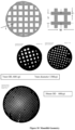
- Figure 2 shows the actual structure of three carbonised monoliths of ⁇ 7, 20 and 30mm diameter.
- inter-particle voids are spaces formed within a structure that has been created by sintering solid partially cured resin particles and carbonising and activating the resulting sintered material.
- Such voids may have sizes of the order of about 5 ⁇ m but typically is ⁇ 20% of the size of the powdered resin used to produce the monolith.
- sintering we mean a step which causes the individual particles of phenolic resin to adhere together without the need for a separately introduced binder, while retaining their individual identity to a substantial extent on heating to carbonisation temperatures.
- the particles must not melt after forming so as to produce a molten mass of resin, as this would eliminate the internal open void structure of the article. Even partial melting can degrade the form of the monolithic structure.
- the open void structure (as opposed to the closed cells found in certain types of polymer foams) is believed to be important in enabling formed particles to retain their shape on carbonisation.
- the lignins are a major component of all plant (lignocellulosic) materials. Plants comprise crystalline cellulose, hemi (amorphous) cellulose and lignin. The proportion of the three components varies with the precursor which range from grasses, plants such as hemp to hard and soft woods. Typical compositions are shown in 3.
- Lignin is an amorphous copolymer of phenyl propene units formed via a radical copolymerisation of coumaryl alcohol, coniferyl alcohol and sinapyl alcohol ( Figure 4A ).
- Figure 4B The three dimensional nature of a soft wood (spruce) derived lignin is shown schematically in Figure 4B .
- lignin is essentially a naturally occurring, medium molecular weight phenolic resin where the thermoplastic behaviour is a function of the composition which in turn depends on the precursor. As such it gives a high carbon yield on pyrolysis which is critical to achieve the good binder performance we have observed. Surprisingly however the binder performance is significantly enhanced when compared with synthetic phenolic resins of similar molecular weight. Whilst not wishing to be bound by the explanation the applicants believe that this is due to different melt flow characteristics of the two materials. As such the performance of the lignin materials in the processes described in this specification will be influenced by the melt flow and therefore by the precursor material.
- lignin is generally a waste by-product of bio-refining and paper making where cellulose is generally the desired component.
- lignin is generally produced as the acidic black liquor although it is also produced as a relatively pure material by for instance the Organosolv process ( US Patent 3,585,104 Kleinert) which is used to extract the lignin in solution which is then precipitated.
- the lignin from the traditional Kraft process cannot be used in the process of this invention due to the high level of contaminants but more critically its water solubility which precludes the use of a conventional aqueous extrusion processes.
- the preferred material is produced by processes such as Organosolv and is a high purity water-insoluble powder that can be used in extrusion and other forming processes. In particular its metal content is low, preferably only a few ppm.
- the Organosolv process involves digesting subdivided fibrous plant material in a digester at an elevated digesting pressure and at an elevated digesting temperature without pre-impregnation of pulping agent.
- aqueous mixtures of the lower aliphatic alcohols such as methanol, ethanol, propanol
- aqueous mixtures of the lower aliphatic ketones such as acetone
- aqueous mixtures containing both lower aliphatic alcohols and lower aliphatic ketones are appropriate pulping agents, aqueous mixtures of ethanol in the range 20% - 75 wt% ethanol being preferred.
- the claimed process comprises:
- An advantage for this invention is that the cost of the lignin, essentially a waste material, is lower than synthetic oil derived phenolic resins. It can also be available in very large quantities.
- a further advantage of lignin in this invention is that as it is essentially a naturally occurring phenolic resin the carbon yield during pyrolysis is high, typically around 30%. This is lower than that achieved with the synthetic phenolic resin, primarily reflecting loss of the side chains, but is none the less significantly higher than the ⁇ 20% yield typically achieved with cellulosic precursors.
- the invention is concerned with the production of complex structures that can be extruded or moulded and comprise a range of precursor particles combined with lignin either as the binder (first phase) or as the main structural component.
- the lignin can be used in combination with porous resin structures produced by methods such as those disclosed in US 8383703 .
- the similar carbon yield and volume shrinkage of the lignin binder and resin matrix components gives good strength at a low binder level, maximising the mesoporosity in the finished carbon.
- the second phase is the fully cured meso/macro porous resin the binder concentration should be adjusted to give the maximum strength and attrition resistance consistent with maintaining the maximum concentration, and therefore pore structure properties, of the second phase.
- the active carbon component in the monolithic structures has the same micro : meso/macro binary pore structure that has been shown to be the critical component in the bead carbons used in extra-corporeal blood processing, and the examples later in this document demonstrate similar adsorption properties for the small, middle and larger molecule weight molecules.
- this performance is surprising in its own right but has now been shown to be critically dependent upon the channel size (W) and structure of the monoliths (see Figure 1 ).
- W channel size
- Figure 1 it has been shown that the cell density should exceed 600 cells per square inch (cpi) and preferably exceed 1000 cpi.
- haemolysis in the blood stream flowing through the monolith is significantly reduced when compared to the packed beds of beads used in the earlier work.
- the time to the point where clotting is observed increase from 10-12 minutes in packed bead column to 20-25 minutes in the monoliths.
- heparin cannot be eliminated from the procedures it has been shown that the level required can be dramatically reduced and this then substantially reduces the risk of internal bleeding which is a significant problem.
- Mesoporous monoliths are able to remove a range of uraemic toxins from plasma and blood including the albumin bound toxins indoxyl sulphate and p-cresyl sulphate which remain in the blood after haemodialysis and have been linked to progression of CKD, the high morbidity and mortality rates for end stage renal disease (ESRD) and cardiovascular disease (CVD).
- the monoliths are also able to remove larger sized biotoxins such as the inflammatory cytokines and other contrary substances linked to ESRD.
- Acute-on-chronic liver disease is characterised by a rapid loss of function in up to 90% of a patient's liver cells.
- Extracorporeal liver support devices could detoxify the blood of ACLF patients and act as a bridge to transplantation.
- the carbon monoliths are designed to adsorb small and medium-sized hydrophobic molecules (e.g. cytokines) that cannot be removed by conventional water-based dialysis.
- the controlled pore structure carbons are also effective at removing the albumin bound liver toxins which include tryptophan, cholic acid and bilirubin. To date these tests have only been carried out using the bead form carbons which demonstrate clearly the critical role of pore structure.
- the carbon must contain both the larger pores necessary for the complex to initially become associated with the carbon and then for the smaller pores to adsorb the toxin. This toxin adsorption is then related to the size and shape of the toxin and the structure of the micropores.
- SRIS systemic inflammatory response syndrome
- the carbon beads have been shown to be successful in removing a range of inflammatory cytokines including TNF, IL-6 and IL-8 as well as both bacterial endotoxin and exotoxins from blood. This work has shown that the monoliths can also remove TNF ⁇ , the most difficult of the SIRS related molecules to remove, from both blood and plasma
- Alcohol poisoning is a significant problem, particularly in the countries of the former Soviet Union.
- lignin can be beneficially be used as a binder (second component) for a first component which comprises mesoporous particles of a fully cured phenolic novolak resin comprising between 15 and 25 pbw HMTA per 100 pbw novolac.
- first component which comprises mesoporous particles of a fully cured phenolic novolak resin comprising between 15 and 25 pbw HMTA per 100 pbw novolac.
- the method of production of the structured composite material can be by either extrusion or pressurised moulding.
- the first component preferably with a particle size between 20 and 100 ⁇ m is mixed with between 10 and 40% volume of the lignin binder powder (second component) along with the extrusion aids.
- the extrusion aids are well known to those skilled in the art but comprise primarily cellulose compounds such as Methocell, polyethylene oxide and other additives used to modify and control the rheology of the dough and water.
- the amount of water to be added depends on the porosity of the first component but should be sufficient to give a flexible dough.
- Embodiments of present materials incorporate a wide range of pore structures depending on the nature of the first component.
- the first component is the resin powder produced by solvent pore forming
- the final material contains both micropores and relatively large mesopores ((20-50nm) and optionally macropores (>50nm).
- a precursor resin formulation is used which comprises a proportion of pore former of for instance 250 parts ethylene glycol to 100 parts of resin-forming components.
- This provides macropores that are useful e.g. for adsorption of peptides and proteins e.g. cytokines in blood.
- Larger macropores in carbonised and optionally activated material of size e.g. 200-2000nm arise from voids between the sintered particles of resin precursor and provide pathways for gas or liquid to permeate into the structure, but do not adsorb protein.
- nucleophilic component there is used a phenolic novolac which, because it is already partly polymerized, makes the polymerization to the desired resin a less exothermic and hence more controllable reaction.
- the preferred novolacs have average molecular weights (AMW) in the range of from 300 to 3000 prior to cross-linking, corresponding to a degree of polymerisation (DP) with respect to phenol of about 3-30 and may be solids with melting points in the region of 100°C.
- AMW average molecular weights
- DP degree of polymerisation
- Novolac resins of AMW less than 2000 and preferably less than 1500 form resins which on carbonisation tend to produce carbons with desired pore size distributions using lower amounts of pore former.
- Novolacs are thermally stable in that they can be heated so that they become molten and cooled so that they solidify repeatedly without structural change. They are cured on addition of cross-linking agents and heating. Fully cured resins are infusible and insoluble.
- the nucleophilic component may be provided alone or in association with a polymerization catalyst which may be a weak organic acid miscible with the novolac and/or soluble in the pore former e.g. salicylic acid, oxalic acid, phthalic acid orp-toluene sulfonic acid (but preferably not for resins intended to be carbonied as the addition of sulphur-containing compounds is undesirable).
- a polymerization catalyst which may be a weak organic acid miscible with the novolac and/or soluble in the pore former e.g. salicylic acid, oxalic acid, phthalic acid orp-toluene sulfonic acid (but preferably not for resins intended to be carbonied as the addition of sulphur-containing compounds is undesirable).
- the concentration of novolac in the pore former may be such that when combined with the solution of cross-linking agent in the same pore former the overall weight ratio of pore former to (novolac + crosslinking agent) is at least 125: 100 by weight.
- the actual ratios of novolac:pore former and crosslinking agent:pore former are set according to convenience in operation e.g. in the case of the process disclosed in WO 2008/043983 (Tennison ) by the operational requirements of a bead production plant and are controlled by the viscosity of the novolac:pore former solution such that it remains pumpable and by the ratio of crosslinking agent:pore former such that the crosslinking agent remains in solution throughout the plant.
- HMTA is used as cross-linking agent.
- HMTA for a partially cured and sinterable resin material there may be employed up to 5 pbw of HMTA per 100 pbw of novolac. However for the production of the mesoporous/macroporous resin it is essential that the resin is fully cured. HMTA or other cross-linking agents are used at a proportion of 15 to 25 pbw. Whilst the stoichiometric amount required for complete curing is approximately 15%, a level of 20% is preferably used to guarantee full curing. This ensures formation of the solid resin with maximal cross-linking degree and ensures the stability of the mesopore structure during subsequent removal of the pore former. At lower degrees of cross linking the structure tends to collapse during removal of the pore former prior to pyrolysis.
- the pore former also acts as solvent.
- the pore former is preferably used in sufficient quantities to dissolve the components of the resin system, the weight ratio of pore former to the total components of the resin system resin being preferably at least 1.25:1.
- the pore former may be, for example, a diol, a diol-ether, a cyclic ester, a substituted cyclic or linear amide or an amino alcohol e.g. ethylene glycol, 1,4-butylene glycol, diethylene glycol, triethylene glycol, ⁇ -butyrolactone, propylene carbonate, dimethylformamide, N-methyl-2-pyrrolidinone and mono ethanolamine, ethylene glycol being preferred, and where the selection is also limited by the thermal properties of the solvent as it should not boil or have an excessive vapour pressure at the temperatures used in the curing process.
- the pore former In the presence of a low level of pore former the pore former is compatible with, and remains within, the cross-linked resin domains, (e.g., ⁇ 120 parts/100 parts Novolac for the Novolac-HMTA-Ethylene Glycol reaction system), whilst the remainder forms a solution with the partially cross-linked polymer between the domains.
- the pore former adds to the light polymer fraction increasing the volume of material in the voids between the domains that gives rise to the mesoporosity and optionally macroporosity.
- the higher the pore former content the larger the wider the mesopores up to macropores and the higher the pore volume.
- This phase separation mechanism provides a variety of ways of controlling the pore development in the cross-linked resin structures. These include chemical composition and concentration of the pore former; chemical composition and quantity of the cross-linking electrophilic agents, presence, chemical nature and concentration of modifying nucleophilic agents, chemical composition of phenolic nucleophilic components (phenol, novolac), presence, chemical nature (acidic, basic), the presence of water within the solvent and concentration of any curing catalyst if present.
- the pore former should also, in the case of phenolic resins, be compatible with water and/or other minor condensation products (e.g. ammonia) which are formed by elimination as polymerization proceeds, and the pore former is preferably highly miscible with water so that it can be readily removed from the polymerized resin by washing.
- minor condensation products e.g. ammonia
- a resin powder is desirable with a mean particle size of 20 to 100 ⁇ m, preferably around 40 ⁇ m.
- This is manufactured by producing a mixed solution of the resin component and the crosslinking agent in the pore forming solvent.
- This typically comprises a medium molecular weight novolac, although the molecular weight is not critical, and HMTA dissolved in the pore forming solvent, preferably ethylene glycol (EG).
- EG ethylene glycol
- a critical requirement for the pore forming solvent is that it dissolves both the resin and crosslinking agent.
- the two cold solutions are then mixed.
- the novolac:hex composition is 100 parts:20 parts whilst the ratio of EG: HEX+novolac is increased to increase the meso/macro pore volume.
- the mixed solution is then cured which requires a temperature of approximately 150C. This can either be in batch mode, where the mixture is poured into trays and then placed into a preheated oven, and which gives rise to blocks of cured resin which then require granulation, or in a continuous rotary oven where the product may be large granules.
- the glycol can be removed by washing or vacuum drying and the particle size of the cured resin for washing is preferably a 1-2mm which can be produced by granulation.
- Standard monoliths of carbon produced from phenolic resins by existing processes have a microporous/inter-particle macroporous void structure and introduction of mesoporosity or macroporosity in the individual particles of resin precursor and then of carbon was not initially intended.
- Forming monoliths having mesoporosity or macroporosity intentionally introduced into the structure of the individual particles from which the monolith is formed gives rise to a number of difficulties. Normally to produce the microporous monoliths it is necessary that the partially cured resin should be in a sinterable state, and that requirement limits the amount of cross-linking agent that can be used.
- the meso/macro porous structure of the individual particles can only be stabilised by complete cure, typically using at least 15 parts of HMTA and preferably 20 parts curing agent per 100 parts resin. This material cannot be adequately sintered and it is therefore essential to use a separate binder component.
- the lignin typically at between 10 and 30% weight loading is mixed with the meso/macro porous resin power described above.
- the extrusion aids comprising materials well known to those skilled in the art, but comprising primarily methyl cellulose and polyethylene oxide, are mixed with the precursor powder and lignin powder. Water is then added to produce a pliable dough. The resulting dough can then be moulded or extruded and then dried. At this stage the resulting green body is fired to a minimum of 500°C, preferably greater than 700°C which is required to decompose the extrusion aids which at lower temperatures tend to block the pore structure.
- the cell geometries that have been produced are limited at the high cell density end of the spectrum by the pressure drop through the monolith when in use, especially when using complex, high viscosity fluids such as blood but also the by the ability to produce the fine channel and hole structure in the extrusion die and the pressures required to actually extrude the dough.
- the geometry at the low cell density end of the spectrum is limited by the performance of the carbon monolith in the separation process. We have shown that the separation performance drops rapidly at below approximately 600cpi.
- the structures of the monoliths produced and tested in this application are summarised below for the three typical monoliths that have been used with nominal carbon diameters of 7, 20 and 32mm.
- a key factor here is the monoliths shrink by approximately 30% radially and axially. This results in a significant increase in cell density between the extruded resin monolith as can be seen for the 7.9mm monolith where the cell density in the resin is 645 but in the carbon is 1315.
- the transformation of the lignin bound structures into nanoporous structures is performed by carbonisation, i.e. high temperature treatment in an inert atmosphere and at temperatures from ⁇ 500°C upwards and where necessary activation.
- the pyrolysis process begins at about 400°C and is largely complete by around 700°C although further small weight losses continue up to around 1400°C.
- surface area development in the polymeric components is only significant above around 700°C at which point the material is not strictly carbon but a pyropolymer.
- the inert atmosphere for pyrolysis can be secured by flowing suitable inert gas. Nitrogen and argon can be used as inert purge gases at any temperature whilst carbon dioxide is effectively inert up to around 800°C in the absence of catalytic metals.
- Vacuum may also be used. Due to the presence of mesopores in these materials, which provide efficient escape routes for the volatile products, the heating rates employed can be very high - up to 10°C per minute.
- the porosity of the carbon component can be further enhanced by conventional activation methods, e.g. by activation in carbon dioxide above 800°C, which can give surface areas as measured by BET 5 point method of up to 2000 m 2 /g or even up to 3000 m 2 /g. It has been found that "physical" activation with carbon dioxide at the temperatures in the range 850 - 900°C gives rise predominantly to microporosity.
- the walls of the resulting monolithic carbon have a structure with voids between the particles, the individual continuous void space leading into and through the monolith.
- the void structure in the walls of a monolith is controlled by the particles used to form the monolith.
- the macro pore size is typically 20% of the size of the precursor mean particle size.
- the sizes of the individual particles can be varied over a wide range from a maximum particle size of approximately 10% of the wall thickness, t, to a minimum practical particle size of about 10 ⁇ m. This gives a void size within the wall for a 1mm wall thickness of 2-20 ⁇ m.
- the void size fixes the bulk diffusivity of the adsorbent molecules within the matrix.
- the monoliths are square channel monoliths with a cell structure (cells per square cm) where the channel size is between 100 and 2000 ⁇ m and the wall thickness is between 100 and 2000 ⁇ m and with an open area of between 30 and 60% to give a good carbon packing density per unit volume and acceptable mass transfer characteristics.
- TE7/20 resin block was prepared as follows. 2841 g of ethylene glycol was mixed with 4315 g of 66.7% novolac resin in ethylene glycol after which HMTA (570 g) in 4276 g ethylene glycol was added to the mixture and stirred. The liquid mixture was then transferred to two metal trays. These were placed in the oven and ramped to 150°C at 3°C/min at which temperature they were held for 2 hours. During curing ammonia was released which was trapped in a water scrubber. After curing the block of resin was granulated to give approximately 2mm pieces which were suitable for water washing to remove the glycol. After washing and drying the resin granules were jet milled using a Hosokawa 100AFG mill to give a powder with mean a particle size of 40 ⁇ m. The particle size distribution is shown in Figure 5 .
- a matrix of compositions was prepared by producing a mixed solution of the novolac resin and HMTA in the glycol solvent. This was placed in trays and cured at 150°C for 2 hours, after which it was crushed, water washed to remove the glycol and then milled to a fine powder ( ⁇ 100 ⁇ m) ( Figure 5 ). This was then mixed with water and cellulose ether (Methocell) and extruded into 3mm rods. After drying at room temperature the rods were carbonised at 80°C in flowing carbon dioxide. The density of the carbonised monoliths is shown in Figure 6 .
- Rods were produced using the fully cured mesoporous resin as the main component of the matrix and non-porous phenolic resin with varying degrees of cure as the binder matrix.
- the binder phase comprised a standard novolac resin cured using either 3 parts or 5 parts weight HTMA (or used in its uncured state.
- the partially cured resins were prepared by co-milling either 3 or 5 parts of HTMA and novolac (J1098) powder. The mixed powder was then cured in small quantities at 150°C for 2 hours after which it was re-milled to ⁇ 100 ⁇ m.
- the rods were formed by nixing these milled resin powders with the milled mesoporous resin powder, forming this into a dough using water and Methocell and extruding this into 3mm rods.
- the rods were dried at room temperature and were then carbonised at 800°C in flowing carbon dioxide.
- Figure 9A shows the impact of the using the 5pt HMTA cured resin as the binder
- Figure 9B shows the impact of using the uncured novolac resin as the binder. It can be seen that at 50% binder addition, there has been a ⁇ 40% loss in porosity using the cured resin binder but an 80% porosity loss with the uncured novolac binder. It can be seen that for the 5% HTMA (HMTA5) structures the loss in porosity is greater than would be expected from dilution alone.
- the pore volume should have reduced 1 to 0.5cm 3 /g whereas it was reduced to 0.35cm 3 /g.
- the loss was even greater to 0.2cm 3 /g suggesting significant melt flow and pore filling of the porous resin component.
- Table 1 Formulation of Various Extruded Monoliths Code Monolith Microporous Resin (g) TE7/20 (g) Lignin (g) Water (g) Glycerol (g) ADEPT 023 TE7/Micro 50/50 15 15 0 36 4.2 ADEPT 024 TE7/Lignin 50/50 0 15 15 30 0 ADEPT 025 TE7/Lignin 75/25 0 22.5 7.5 49.6 0 ADEPT 026 TE7/Lignin 90/10 0 27 3 56.4 0 ADEPT 027 TE7/Lignin 75/25 0 22.5 7.5 49.6 0
- the monoliths were extruded using a 7.5mm die with 600 cells per square inch (cpi).
- the extruded TE7/Micro (50/50) monoliths showed a yellow colour, many areas of the monoliths had cracks on the outer surface indicating that the dough was not optimal for extrusion processes.
- the monoliths were dark brown and with increased lignin content, the brown colour intensified. Most importantly, with increase of lignin content, cracks on the monolith outer surface disappeared, and the resulting dried monoliths had smooth outer surface.
- Table 2 Processing of lignin bound mesoporous resin Formulation Wt loss Lignin Resin carbonisation Activation 10 90 54.5 28.2 25 75 55.6 29.1 50 50 54.7 29.3 TE720/micro 60.7 21.7
- the mercury pore size distributions for the materials are shown in Figure 11 . These plots have been truncated at 1000nm as the intrusion volume above this size is related to the inter-particle voids rather than the internal porosity of the spheres.
- the internal pores have a size of 55nm irrespective of the lignin loadings.
- Figure 12 shows the pore volume in the 10-1000nm pore size range.
- the diamond-pattern points are the measured pore volumes whilst the square pattern points are the expected pore volume based simply on dilution of the mesoporous resin with the microporous lignin derived material. This demonstrates that the lignin does block some of the desired mesopores although the loss is acceptable at less than 25% lignin.
- Figure 13 shows the crush strength of the lignin bound mesoporous structures. At the lower levels of lignin (lignin as the binder) it can be seen that from approximately 25 to 55% weight lignin there is a plateau with acceptable crush strength of ⁇ 3Kg. Below 25% binder the strength drops rapidly. Taking account of the pore volume loss shown in Figure 10 it can be seen that around 25% lignin offers the best combination of the pore volume retention and strength.
- the primary purpose of using the lignin as a binder was to produce strong, attrition resistant, structures whilst using the minimum level of level of binder to reduce the loss in pore structure.
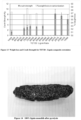
- the lignin can however be used as microporous carbon precursor in its own right. The limitation is that it tends to partially melt and foam during carbonisation, see Figure 14 .
- this foaming characteristic can be completely eliminated through the addition of small amounts of the novolac resin, either as a cured resin powder or as the uncured novolac precursor, to give strong monolithic/extruded structures without the need for complex stabilisation by pre-oxidation.
- Figure 13 shows the crush strength and weight loss for the carbonised TE7/20 resin - lignin composite monoliths through to the high lignin content formulations.
- the weight loss is essentially independent of the lignin content confirming the similar process characteristics of the synthetic and natural phenolic resins.
- the drop in strength at 80% lignin and higher is due to the foaming characteristic of the lignin during pyrolysis.
- the structure of a monolith made from 100% lignin after pyrolysis is shown in Figure 14 (Referennce). It is clear that it is possible to make monoliths comprising almost entirely lignin as the precursor in the range 70-80% lignin.
- Monolithic carbon structures have been produced using lignin as the second phase and milled natural precursors as the first phase.
- Three materials have been evaluated as the first phase - rice husks, hemp shives and flax waste although the methods are equally applicable to other first phase materials.
- the components were mixed in a z-blade mixer for 45 minutes.
- the viscoelastic dough that was formed was then extruded to produce 650 cells/square inch (CPI) monoliths.
- the monoliths were carbonised in flowing carbon dioxide.
- the furnace was ramped from ambient to 700°C at 1C/minute and held for 10 minutes before cooling.
- This can then be removed if required depending on the final applications. It can in principle be removed before or after activation by extraction with sodium hydroxide but if the monolith is to be activated it is preferably removed after activation as residual sodium catalyses the activation process and can cause problems. It can be removed by soaking the activated monolith in 1M NaOH solution for 5Hr at 80°C, rinsing with water and then repeating the extraction step.
- the monolith is thoroughly washed to remove any residual sodium hydroxide or sodium silicate and then with 0.5M HCl followed by further water washing. The monoliths were then thoroughly dried. After this process there was approx. 3% residual silica in the monoliths.
- the pore structure properties of the materials are summarised in Table 2 with the nitrogen adsorption isotherms in Figure 19 . It can be seen that the materials that were carbonised, activated and then washed have the highest surface area.
- hemp shives may be processed as described above.
- Bead materials were produced by the method described in WO 02/12380 where the resin components (novolac and HMTA), dissolved in ethylene glycol at ⁇ 100°C, are added to mineral oil at 150°C in the presence of a dispersant.
- the mixture is mechanically stirred using a paddle stirrer and the size of the beads is primarily controlled by the stirrer rotation speed.
- the temperature drops and the mixture is reheated to 150°C to complete the bead cure.
- the beads are then filtered from the oil and thoroughly washed in hot water to remove the EG pore former. After drying the beads were carbonised in flowing carbon dioxide at 800°C.
- the meso-macro pore structure of these carbons is controlled by the ratio of the total resin solids (novolac resin plus HMTA) to ethylene glycol.
- the compositions are shown in the table below. As discussed above the mass of novolac and HMTA is kept constant and only the mass of ethylene glycol (EG) is varied. In the case of the Novolac resin J1098F the composition varies between E3 and E6. The table also shows the nitrogen adsorption characteristics of these materials. It can be seen that the density of the J1098F based carbon decreases steadily as the EG content is increased reflecting the increased meso/macro pore volume. Across this range the BET area, which is predominantly present in the micropores remains essentially unchanged.
- the pore structures of the J1098F derived carbons are shown in Figure 15 and show the steady increase in mean pore size and pore volume as the EG level is increased reaching a mean pore size of 800-900A.
- the beads After filtration from the oil the beads are split into two fractions, the first of which is water washed 3 times with hot deionised water. The second fraction is vacuum dried at 160°C. After either washing or drying to remove the ethylene glycol pore former the porous resin is carbonised at 800°C in flowing carbon dioxide.
- the actual TOSL4 formulation for the preparation was 80g Novolac/20g OSL/20g HMTA/180g EG.
- the tests described in the following examples relate to chronic kidney disease and were carried out using a variety of monoliths with nominal diameters of 7mm, 18mm and 28.5mm, flow rates and reservoir capacities which are summarised below.
- the monolith geometry is shown schematically in Figure 18
- S W + T
- W W + T
- wall thickness(t) is independent of the cell geometry and is a function of the extrusion requirements.
- test data Whilst the majority of the test data is presented based on direct measurements of concentration vs time, the results have also been normalised by determining the challenge removal and weight uptake on the carbon as a function of the number of passes through the monolith.
- PCS and IS are both small molecules that can adsorb in the micropore structure of the carbons.
- the rate of adsorption or removal is maximised for the smallest, 7mm, monoliths.
- the kinetics of both the 18 and 28mm monoliths is significantly reduced. This difference in rate is also apparent for IL6 ( Figure 24 ).
- IL6 Figure 24
- FIG. 24 shows that in this case there is a significant improvement in performance with the higher cell density monolith.
- the 25cm x ⁇ 30mm OD monoliths derived from 25 wt% lignin and 75 wt% TE7 resin prepared as in Examples 2 and 3 were mounted into the ends of large plastic syringes and sealed in place with shrink wrap tubing. This can be seen to the side of the pump system in Figure 20 .
- the monolith testing was carried out using both plasma and healthy donor whole bloods (400 ml from each donor) with sodium heparin anticoagulation purchased from Cambridge Bioscience Ltd (UK). These were then dosed with the challenge molecules.
- the feed solution, blood or plasma, was continuously recycled from the reservoir through the column at 300ml/minute.
- the monoliths were extruded using a 42mm die with a nominal 600cpi cell density as described in example 5A After drying the monolith was carbonised at 750C in flowing carbon dioxide and then activated at 850C in flowing carbon dioxide.
- the donor blood was spiked with 5 mL of 33% ethanol per blood container (approximately 380 mL).
- An erythrocyte suspension was used as donor blood, which was leucocyte-free.
- the haemoperfusion session was run for 60 minutes using the standard dialysis equipment at flow rate 140 mL/min (Fresenius dialysis system). The tests were carried out using the carbon monoliths, diameter 22-24 mm, described in (a). The results are shown in Table . It can be seen that the monoliths were effective at significantly lowering the blood alcohol and that nearly all the observed alcohol removal took place in the first 30 minutes. Table 8. Alcohol concentration in the animal blood before and during HP Time, min Alcohol content in blood, ⁇ Degree of alcohol removal, % Before injection ---- - 0 (immediately after injection) 3.04 0 30 min of HP 1.31 57 60 min of HP 1.24 60
- HP haemoperfusion
- the biochemical parameters of blood remained unaffected by haemoperfusion over the carbon monolith.
- SIRS systemic inflammatory response syndrome
- SEB Staphylococcal enterotoxin B
- the monolithic carbon is capable of removing the cytokine TNF ⁇ from both flowing blood ( Figure 29 ) and flowing plasma ( Figure 27 ) it is reasonable to assume that the SEB would also be removed using monoliths in place of beads in a haemoperfusion application.
- Acute-on Chronic liver disease is characterised by a rapid loss of function in up to 90% of a patients liver cells.
- Extracorporeal liver support is targeted at the detoxification of patient blood as a bridge to transplantation. This requires the removal of a wide range of both small molecule toxins and albumin bound toxins such as phenol, tryptophan, cholic acid and bilirubin.
- the beads were incubated with 5.4 ml of fresh human plasma spiked with 2 ⁇ mol/ml of phenol, 0.1 ⁇ mol/ml of tryptophan or cholic acid or 0.3 ⁇ mol/ml of bilirubin. 0.6ml samples were collected at 5, 15, 30 and 60minutes and were analysed using standard test methods. Tests were carried out using 5 replicates.
- the monoliths used in the tests were 7mm diameter, 95mm long, 25%weight lignin bound 600 cpi meso/macro porous monoliths as described in Example 5A.
- the monoliths had a bimodal pore structure with 1nm micropores and ⁇ 80nm macropores. This is identical to the A4 bead carbons used in (a).
- SIRS systemic inflammatory response syndrome
- SEB Staphylococcal enterotoxin B
- the monolithic carbon is capable of removing the cytokine TNF ⁇ from both flowing blood ( Figure 29 ) and flowing plasma ( Figure 27 ) it is reasonable to assume that the SEB would also be removed using monoliths in place of beads in a haemoperfusion application.
- Acute-on Chronic liver failure is characterised by a rapid loss of function in up to 90% of a patients liver cells.
- Extracorporeal liver support is targeted at the detoxification of patient blood as a bridge to transplantation. This requires the removal of a wide range of both small molecule toxins and albumin bound toxins such as phenol, tryptophan, cholic acid and bilirubin.
- the beads were incubated with 5.4 ml of fresh human plasma spiked with 2 ⁇ mol/ml of phenol, 0.1 ⁇ mol/ml of tryptophan or cholic acid or 0.3 ⁇ mol/ml of bilirubin. 0.6ml samples were collected at 5,15, 30 and 60minutes and were analysed using standard test methods. Tests were carried out using 5 replicates.
- the monoliths used in the tests were 7mm diameter, 95mm long, 25%weight lignin bound 600 cpi meso/macro porous monoliths as described in Example 5A.
- the monoliths had a bimodal pore structure with 1nm micropores and ⁇ 80nm macropores. This is identical to the A4 bead carbons used in (a).
Landscapes
- Chemical & Material Sciences (AREA)
- Organic Chemistry (AREA)
- Chemical Kinetics & Catalysis (AREA)
- Analytical Chemistry (AREA)
- Health & Medical Sciences (AREA)
- Engineering & Computer Science (AREA)
- Heart & Thoracic Surgery (AREA)
- Vascular Medicine (AREA)
- Life Sciences & Earth Sciences (AREA)
- Biomedical Technology (AREA)
- Hematology (AREA)
- Veterinary Medicine (AREA)
- Public Health (AREA)
- Anesthesiology (AREA)
- General Health & Medical Sciences (AREA)
- Animal Behavior & Ethology (AREA)
- Thermal Sciences (AREA)
- Physics & Mathematics (AREA)
- Nanotechnology (AREA)
- Inorganic Chemistry (AREA)
- Cardiology (AREA)
- Biodiversity & Conservation Biology (AREA)
- Cell Biology (AREA)
- Molecular Biology (AREA)
- Carbon And Carbon Compounds (AREA)
- Solid-Sorbent Or Filter-Aiding Compositions (AREA)
Description
- This invention relates to a method for producing complex shaped nanoporous materials through the use of lignin as a binder for pyrolysable precursors.
- Known methods for the production of complex shaped controlled porosity adsorbent material are discussed in
WO 2004/087612 (Blackbum and Tennison - An alternative route is to take an activated carbon powder and form this directly into the final shape. In this instance a range of polymeric binders have been used that remain in the final product. The main drawback to this route is that high levels of binders are required and these then tend to both fill the pores of the activated carbon powder and encapsulate the powder, leading to a marked reduction in adsorption capacity and a deterioration in the adsorption kinetics. The presence of the polymeric phase also degrades the physical and chemical stability of the formed material, severely limiting the range of applicability.
- A further alternative is to take a formed ceramic material, such as a multichannel monolith, and to coat this with a carbon forming precursor such as a phenolic resin. It can then be fired and activated to produce a ceramic-carbon composite. The main limitations of this route are the cost associated with the ceramic substrate and the relatively low volume loading of carbon. At high degrees of activation it is possible to produce a mesoporous carbon although the carbon volumetric loading and the mechanical stability of the carbon is further reduced.
- The applicants have previously developed methods for making carbonised and optionally activated monoliths from phenolic resin precursors. Monolithic porous carbon can be made by partially curing a phenolic resin to a solid, comminuting the partially cured resin, extruding the comminuted resin, sintering the extruded resin so as to produce a form-stable sintered product and carbonising and activating the form-stable sintered product.
EP 0 254 551 (Satchell et al.WO 02/072240 (Place et al.EP 0 254 551 - In this process for producing carbon monoliths, the resin cure is controlled so that it is sufficient to prevent the resin melting during subsequent carbonisation but low enough that the resin particles produced during the milling step can sinter during subsequent processing. The amount of crosslinking agent and the temperature and duration of the partial curing step are selected as to give a degree of cure sufficient to give a sinterable product, and such that a sample of the partially cured solid when ground to produce particles in the size range 106-250µm and tableted in a tableting machine gives a pellet with a crush strength which is not less than 1 N/mm. Preferably the pellet after carbonisation has a crush strength of not less than 8 N/mm.
- The comminuted resin particles may have a particle size of 1-250µm, in embodiments 10-70µm. In further embodiments the resin powder size is 20-50µm which provides for inter-particle channels of size of 4-10µm with an inter-particle channel volume of 30-40%. The size of the particles is selected to provide a balance between diffusivity through the inter-particle voids and within the particles.
- As disclosed in
US 6964695 (Place et al., Carbon Technologies ) the milled powder can then be extruded to produce polymeric monolithic structures with a wide range of cell structures, limited only by the ability to produce the required extrusion die, or other forms such as rods, tubes, trilobes etc. Suitable dies are well known to those skilled in the art. At this stage the monolith has a bimodal structure - the visible channel structure with either the central channel in a simple tube or the open cells in a square channel monolith of typically 100-1000µm cell dimension and cell walls with thickness typically 100- 1000µm and the inter-particle void structure within the walls generated by the sintered resin particles. - Carbonisation takes place preferably by heating above 600°C for the requisite time e.g. 1 to 48 hours and takes place under an inert atmosphere or vacuum to prevent oxidation of the carbon. On carbonisation the material loses about 50% weight and shrinks by about 50% volume but, provided the resin cure stage was correctly carried out, this shrinkage is accommodated with little or no distortion of the monolith leading to a physical structure identical to that of the resin precursor but with dimensions reduced by -30%. The inter-particle void size is also reduced by ~30% although the void volume (ml/ml) remains essentially unaltered. During carbonisation the microstructure of the porous carbon develops, particularly at temperatures above 600°C. After carbonisation there may be partial blocking of the microstructure by the decomposition products from the carbonisation process. These blockages may be removed by activation to provide rapid access to the internal structure of the carbon that may be desirable for the operation of the monoliths as adsorption devices.
- This production route is limited to the use of Novolac resins and this in turn limits the pore structure that can be produced to the approximately 1nm pores that are characteristic of all novolac derived carbons and larger macropores, typically greater than 1µm, that are produced by the voids between the sintered particles. It is not possible by this route to produce products with pores in the large meso-small micro range of sizes.
- In
US 2013/0072845 (Tennison et al .) a method is described for extending the porosity of the above structures to include meso and or small macro pores in addition to the micropores that derive from the novolac resin. In this invention solid particles of a first phenolic resin which is partially cured so that the particles are sinterable but do not melt on carbonisation are mixed with particles of a second phenolic resin that has a greater degree of cure than said first phenolic resin and has a mesoporous and/or macroporous microstructure generated by solvent pore forming that is preserved on carbonisation; forming the mixture into a dough; extruding the dough to form a shaped product and stabilizing its shape by sintering. - In the above method, the dough may be extruded to form a shaped body having walls defining a multiplicity of internal channels for fluid flow, the channels being directed along the extrusion direction e.g. as discussed in relation to
Figure 1 . There may further be carried out the step of carbonising the resin, and optionally activating the carbonised resin. - In this production route the secondary, highly cured, meso/macro porous resin component is not strongly bound into the structure due to its high degree of cure but rather is trapped in a cage formed by the sinterable resin component. This approach limits the amount of the second material than can be incorporated due to the requirement to form the cage structure. This leads to a reduction in strength when compared to the materials produced entirely from the sinterable resin particles. The extent of the larger pore structure is also limited by dilution of the matrix with the first resin component. This production route can also be used with second components other than phenolic resin such as activated carbons but in this instance differential shrinkage between the particles comprising the cage and the second component during the pyrolysis process leads to stress cracking and a further reduction in mechanical strength. Thus whilst it is possible to produce complex shapes the reduced meso/macro pore capacity and strength limits there used in demanding applications such as blood filtration.
-
US 5 254 639 A discloses a method to produce porous carbonised resins from lignin and phenolic novolac resin. - The production of the large meso/small micro pore carbons is described in
US patent 8383703 (Tennison et al., 2103 ) which is incorporated herein by reference. The preferred route for producing these materials is through the use of pore formers where ethylene glycol is the preferred component although other solvents may also be used. These meso/macro porous resins can be produced either as beads or as powders. In the routes described inUS 2008/025907 (Tennison et al. ) the precursors, typically comprising the novolac resin and the curing agent (typically hexamethylenetetramine (HTMA)) are dissolved in the pore forming solvent (typically ethylene glycol) in the ratios necessary to generate the required pore structure and degree of cure. The mixture can either be cured by dispersing in hot oil to form beads or placed in trays and cured in an oven. In the latter case the block of cured resin is subsequently processed by milling to give either the finished powder or a precursor for extrusion. The limitation of this route is the strength, attrition resistance and control of porosity in monolith materials produced by this route is insufficient to allow these materials to be used in demanding applications such as blood filtration. - There is therefore a requirement for a production route that permits the production of complex shaped nanoporous carbons with multimodal pore structures with sufficient strength and attrition resistance to allow their use in applications such as haemofiltration.
- One problem with which the invention is concerned is how to bind these highly cured porous resins, or other materials, into the structure to give a high strength, attritionresistant structure.
- In one aspect, the invention provides a method for producing a carbonised monolith structure from a first component which comprises mesoporous particles of a fully cured phenolic novolak resin comprising between 15 and 25 pbw HMTA per 100 pbw novolac and 10-40% by weight of a second component which comprises water-insoluble powdered lignin, said method comprising:
- mixing the first and second components;
- producing an uncarbonised monolith structure from the mixture by extrusion; and
- forming from the uncarbonized monolith structure the carbonised monolith structure comprising carbonised particles bound with carbonised lignin, wherein the carbonised particles exhibiting both mesoporosity and macroporosity are dispersed in a matrix of microporous particles with voids between the particles defining paths for fluid to flow into and through the structure;
- microporosity referring to a material possessing pores with diameter <2 nm, as measured by nitrogen adsorption methods and as defined by IUPAC, mesoporosity referring to a material possessing pores with diameter from ca. 2 nm to ca. 50 nm, as measured by nitrogen adsorption and mercury porosimetry methods and as defined by IUPAC, and macroporosity referring to a material possessing pores with diameters larger than 50 nm as measured by mercury porosimetry methods and as defined by IUPAC.
- In another aspect, the invention provides a method for producing a carbonised monolith structure from a first component which comprises mesoporous particles of a fully cured phenolic novolak resin comprising between 15 and 25 pbw HMTA per 100 pbw novolac and 10-40% by weight of a second component which comprises water-insoluble powdered lignin, said method comprising:
- mixing the first and second components;
- producing an uncarbonised monolith structure from the mixture by pressurised moulding; and
- forming from the uncarbonized monolith structure the carbonised monolith structure comprising carbonised particles bound with carbonised lignin, wherein the carbonised particles exhibiting both mesoporosity and macroporosity are dispersed in a matrix of microporous particles with voids between the particles defining paths for fluid to flow into and through the structure;
- microporosity referring to a material possessing pores with diameter <2 nm, as measured by nitrogen adsorption methods and as defined by IUPAC, mesoporosity referring to a material possessing pores with diameter from ca. 2 nm to ca. 50 nm, as measured by nitrogen adsorption and mercury porosimetry methods and as defined by IUPAC, and macroporosity referring to a material possessing pores with diameters larger than 50 nm as measured by mercury porosimetry methods and as defined by IUPAC.
- Lignin is essentially a naturally occurring phenolic resin, and can be used as a binder phase with a second phase of fully cured novolak resin. In marked contrast to the problems experienced when using pitch as a binder, as is normally used in commercial activated carbon processes, the use of lignin produces form-stable green materials which show little or no distortion on firing. Without being bound by this explanation we believe that the viscosity, melt flow and carbonisation characteristics of the lignins allows them to bond the second phase particles together without excessive flow which would infiltrate the pore structure of the second phase and would also disperse throughout the matrix giving poor bonding. These materials then convert to carbon with a high yield of typically around 30% without the addition of any curing agents.
- The lignins have the further advantage that, as essentially naturally occurring phenolic resins, they are compatible and co-soluble with the novolac resins used in the formation of other phenolic resin derived carbons. They cannot be crosslinked in the same way as novolac resins which means that in their pure form they cannot be easily converted to controlled meso-macro pore structure carbons as they melt and foam during pyrolysis. However we have surprisingly found that when processed as a mixture with a standard Novolac resin, or a natural precursor, the melting characteristics of the lignin are suppressed allowing the production of complex shaped and pore structure products, even with very low levels of the second phase material.
- A method is provided for producing a carbonisable shaped resin body which comprises:
- (a) providing solid particles of a pure water insoluble lignin powder and mixing these with particles of the above cured meso/macro porous phenolic resin;
- (b) forming the mixture into a dough; and
- (c) extruding the dough to form a shaped product.
- The dough may be extruded to form a shaped body having walls defining a multiplicity of internal channels for fluid flow, the channels being directed along the extrusion direction. The extruded structure may be carbonised and may be further activated by treating in flowing carbon dioxide at a temperature of at least 850°C, preferably 900°C for a time selected to give a required weight loss which may be at least 20%, preferably 25%. The resulting carbonised material may be a square channel monolith of 100-1000µm cell dimension and cell walls with thickness 100- 1000µm. The cell density may be at least 600 channels per square inch e.g. at least 1000 channels per square inch.
- A monolith structure is also provided which is an elongated body of carbon having walls defining a multiplicity of internal transport channels for fluid flow longitudinally through said body, the carbon comprising particles of microporous and mesoporous and/or macroporous carbon dispersed in a matrix of microporous carbon. The present monolith structure is the product of the method described herein. It may be provided with a shrink wrap covering its longitudinal exterior surface for preventing in use leakage or escape of blood, serum or plasma. A flow-through chamber may be provided for connection into extracorporeal blood treatment apparatus having a flow path for the extracorporeal blood, an inlet for the flow path at one end of the chamber, an outlet for the flow path at an opposed end of the chamber and arranged within the chamber for through-flow of extracorporeal blood a monolith structure as defined above. The wall of the chamber may be of medical grade plastics material and seal to the ends of the monolith may be by compression members and O-rings or the like. It will be appreciated that a minimum of mechanical strength in the monolith is needed to resist the sealing and other forces encountered in manufacture of the through-flow chamber and in service. The invention further provides extracorporeal blood treatment apparatus including a flow-through chamber as defined above.
- The invention further provides carbon having mesopores and micropores/macropores in a bimodal pore distribution and derived by carbonisation of lignin and the above novolac resin for use in the extracorporeal treatment of blood for any of:
- (a) treating chronic kidney disease;
- (b) removal of albumin-bound indoxyl sulphate, p-cresyl sulphate or inflammatory cytokines linked to end stage renal disease;
- (c) treatment of liver disease;
- (d) removal of phenol, tryptophan, cholic acid or bilirubin;
- (e) treatment of sepsis/systemic inflammatory response syndrome;
- (f) treatment of alcohol poisoning; and
- (g) treatment of cardiovascular disease.
- The invention yet further provides a method of extracorporeal treatment of blood which comprises passing the blood in an extracorporeal circuit through a carbon monolith as defined herein for of any of:
- (a) treatment of chronic kidney disease;
- (b) removal of albumin-bound indoxyl sulphate, p-cresyl sulphate or inflammatory cytokines linked to end stage renal disease;
- (c) treatment of liver disease;
- (d) removal of phenol, tryptophan, cholic acid or bilirubin;
- (e) treatment of sepsis/systemic inflammatory response syndrome;
- (f) treatment of alcohol poisoning; and
- (g) treatment of cardiovascular disease.
- The carbon monolith may for example be derived by extrusion of lignin and mesoporous particles of the above fully cured novolac resin.
- The invention is further defined in the accompanying claims to which attention is directed.
- How the invention may be put into effect will now be described by way of example only with reference to the accompanying drawings in which:
-
Figure 1 is a set of three diagrams and one photograph illustrating the structure of a monolith; -
Figure 2 is a photograph showing three carbon monoliths; -
Figure 3 is a table showing the composition of lignocelluloses as a function of the precursor; -
Figure 4A shows formulae for primary lignin components p-coumaryl-, coniferyl- and sinapyl alcohols, dominant building blocks of the amorphous lignin polymer, andFigure 4B is a model structure for spruce-derived lignin; -
Figure 5 shows the particle size distribution of jet-milled resin of Example 2; -
Figure 6 shows density as a function of pore former and HMTA content for the monoliths of Example 3; -
Figure 7 shows the variation in mercury pore volume with HMTA content for the macroporous (TE7) powder and monoliths of Example 3; -
Figure 8 shows 3 point bend test results for the extruded rods of Example 4 and in particular the impact of cured resin content and degree of cure of the microporous resin content on strength of the carbonised extrudate; -
Figure 9 shows the effect of binder resin cure on the pore structure of the monoliths; -
Figure 10 compares the strength and porosity as a function of binder resin concentration; -
Figure 11 shows the impact of lignin binder content on monolith pore structure and compares this with the pore structure of a resin bound monolith; -
Figure 12 shows a comparison of theoretical pore volume based on lignin dilution with observed pore volume; -
Figure 13 shows the change in crush strength and weight loss on carbonisation as function of the lignin:resin ratio ; -
Figure 14 (Reference) is a photograph of a 100% lignin monolith after pyrolysis; -
Figure 15 (Reference) shows the nitrogen pore size distribution of bead carbons as a function of the ethylene glycol pore former (E3 to E6) concentration for a pure novolac resin precursor (ethylene glycol modified J1098F novolac resin); -
Figure 16 (Reference) shows the nitrogen pore size distribution of beads produced from varying resin: organo solv lignin (OSL) ratios and a low ethylene glycol (EG) pore former concentration (E3); -
Figure 17 (Reference) shows the nitrogen pore size distribution of beads produced from varying resin:organosolv lignin (OSL) ratios and an intermediate ethylene glycol (EG) pore former concentration (E5); -
Figure 18 is a schematic of a monolith cross section showing the definition of the unit cell and three shadow graphs showing the actual cross section of 7mm, 600 and 1300 CPI monoliths and a 30mm 600CPI monolith; -
Figure 19 (Reference) shows the nitrogen adsorption isotherms for a rage of rice husk-lignin based monoliths; -
Figure 20 is a block diagram showing a whole blood or plasma perfusion system for small monoliths; -
Figure 21 is a graph showing the removal of IL6 from plasma using the lignin bound monolith and the test system inFigure 20 ; -
Figure 22 shows removal of IS using lignin bound monoliths. IS remaining in the plasma sample after 5, 30, 60 and 120 minutes of circulation through tested AC monoliths: TE7/Lignin (90-10) (inverted triangles), TE7/Lignin (75-25) (triangles), TE7/Micro (50-50) (circles) and TE7/Lignin (50-50) (squares). A control () was also included as a reference (SEM ± n=3); -
Figure 23 shows the PCS (p-cresyl sulphate) remaining in the plasma sample after 5, 30, 60 and 120 minutes of circulation through monoliths: TE7/Lignin (90-10) (inverted triangles), TE7/Lignin (75-25) (triangles), TE7/Micro (50-50) (circles) and TE7/Lignin (50-50) (squares). A control (diamonds) was also included as a reference (SEM ± n=3); -
Figure 24 shows the removal of spiked cytokine marker IL-6 from human plasma pool by carbon monoliths. (A) the IL-6 removal expressed as percentage of IL-6 concentration attime 0; (B) the removal of IL-6 is expressed as ng of IL-6 adsorbed by each gram of activated carbon; -
Figure 25 shows the removal of spiked albumin bound uraemic toxin marker PCS from human plasma pool by carbon monoliths. (A) the percentage of PCS removed; (B) the amount of PCS (µmol) adsorbed by each gram of activated carbon; -
Figure 26 shows the removal of spiked albumin bound uraemic toxin marker indoxyl sulphate (IS) from human plasma pool by carbon monoliths. (A) the percentage of IS removed, (B) the amount of IS (µmol) adsorbed by each gram of activated carbon; -
Figure 27 shows the adsorption of IL6 and TNF from plasma in 30mm diameter lignin bound monolliths; -
Figure 28 shows adsorption of PCS and IS from circulating plasma using 30 mm lignin bound monoliths; -
Figure 29 shows adsorption of PCS, IS, IL6 and TNFα from whole blood using 30 mm monoliths; -
Figure 30 (Reference) shows adsorption of Staphylococcal enterotoxin B (SEB) from human plasma using carbon beads with 1nm pores (carbon 1), 30nm pores (Carbon 5) and 100nm pores (carbon 9); -
Figure 31 shows the amount of tryptophan removed from the spiked human plasma. Samples were collected after the 0.6 ml of AC beads (A-1, A-2, A-3, A-4 and A-5) incubated with 5.4 ml of tryptophan (0.1 µmol/ml) spiked fresh frozen human plasma for 5, 15, 30 and 60 min, and analysed using HPLC. Tryptophan removal was calculated based on the volume of the AC beads. (Mean n=4, ± SEM); -
Figure 32 shows the adsorption kinetics of bilirubin by AC1-5 from spiked plasma. The adsorption kinetics of bilirubin by 0.4 ml microporous carbon (Al), mesoporous carbon (A2) and macroporous carbon (A3, A4 and A5) from 5.6ml 300 µM bilirubin spiked plasma was observed at 4 time points over 60 min of incubation period. (Mean n=5, ± SEM); and -
Figure 33 shows the reduction in Bilirubin content of circulating blood of a bile duct ligation (BDL) animal model of liver failure during haemoperfusion using a macroporous carbon monolith (upper line) and sham control (lower line). - As used herein, the term "microporous" refers to a carbon or other material possessing pores with diameter <2 nm, as measured by nitrogen adsorption and mercury porosimetry methods and as defined by IUPAC.
- As used herein, the term "mesoporous" refers to a carbon or other material possessing alongside micropores, pores with diameter from ca. 2 nm to ca. 50 nm, as measured by nitrogen adsorption and mercury porosimetry methods and as defined by IUPAC.
- As used herein, the term "macroporous" refers to a carbon or other material possessing alongside micropores and mesopores , pores with diameters larger than 50 nm. This is preferably measured by mercury porosimetry methods and as defined by IUPAC, comprises pores of greater than 50nm diameter.
- By "monolithic" is meant that the resulting porous carbon is in a single piece i.e. not granular or not composed of granular carbons bound together by a binder, for instance a polymer etc. and is composed entirely of carbon. The monolithic carbon may contain large transport channels in addition to inter-particle voids within the walls of the transport channels and the macro/meso/microporosity of the individual particles. For a symmetrical monolith (
Figure 1 ) a continuous channel structure is defined by a channel dimension, W, and a wall thickness, t, or for an asymmetric monolith by channel length and width or other relevant dimensions as well as wall thickness t. These fix the ratio of open to closed area and therefore the flow velocity along the channels of the monolith. The walls of monolithic carbon have a void structure providing paths for fluid to flow into and through the carbonaceous body of the monolith. Alternatively the product can be formed as a moulded or extruded structure with similar micro and macro pores but lacking the channel structure.Figure 2 shows the actual structure of three carbonised monoliths of ~7, 20 and 30mm diameter. - In relation to monoliths, inter-particle voids are spaces formed within a structure that has been created by sintering solid partially cured resin particles and carbonising and activating the resulting sintered material. Such voids may have sizes of the order of about 5 µm but typically is ~20% of the size of the powdered resin used to produce the monolith.
- By "sintering" we mean a step which causes the individual particles of phenolic resin to adhere together without the need for a separately introduced binder, while retaining their individual identity to a substantial extent on heating to carbonisation temperatures. Thus the particles must not melt after forming so as to produce a molten mass of resin, as this would eliminate the internal open void structure of the article. Even partial melting can degrade the form of the monolithic structure. The open void structure (as opposed to the closed cells found in certain types of polymer foams) is believed to be important in enabling formed particles to retain their shape on carbonisation.
- The lignins are a major component of all plant (lignocellulosic) materials. Plants comprise crystalline cellulose, hemi (amorphous) cellulose and lignin. The proportion of the three components varies with the precursor which range from grasses, plants such as hemp to hard and soft woods. Typical compositions are shown in 3.
- Lignin is an amorphous copolymer of phenyl propene units formed via a radical copolymerisation of coumaryl alcohol, coniferyl alcohol and sinapyl alcohol (
Figure 4A ). The three dimensional nature of a soft wood (spruce) derived lignin is shown schematically inFigure 4B . - If the higher plants are considered there are two main types of lignin where these precursor molecules are present in different proportions depending on the organic precursor. Hardwoods comprise a mixture of coniferyl and sinapyl building blocks whilst softwood lignin comprises more than 90% coniferyl alcohol. The resulting lignin is essentially a naturally occurring, medium molecular weight phenolic resin where the thermoplastic behaviour is a function of the composition which in turn depends on the precursor. As such it gives a high carbon yield on pyrolysis which is critical to achieve the good binder performance we have observed. Surprisingly however the binder performance is significantly enhanced when compared with synthetic phenolic resins of similar molecular weight. Whilst not wishing to be bound by the explanation the applicants believe that this is due to different melt flow characteristics of the two materials. As such the performance of the lignin materials in the processes described in this specification will be influenced by the melt flow and therefore by the precursor material.
- At present lignin is generally a waste by-product of bio-refining and paper making where cellulose is generally the desired component. In paper making by the Kraft process lignin is generally produced as the acidic black liquor although it is also produced as a relatively pure material by for instance the Organosolv process (
US Patent 3,585,104 Kleinert) which is used to extract the lignin in solution which is then precipitated. The lignin from the traditional Kraft process cannot be used in the process of this invention due to the high level of contaminants but more critically its water solubility which precludes the use of a conventional aqueous extrusion processes. The preferred material is produced by processes such as Organosolv and is a high purity water-insoluble powder that can be used in extrusion and other forming processes. In particular its metal content is low, preferably only a few ppm. - According to the Kleinert patent the Organosolv process involves digesting subdivided fibrous plant material in a digester at an elevated digesting pressure and at an elevated digesting temperature without pre-impregnation of pulping agent. Kleinert explains that aqueous mixtures of the lower aliphatic alcohols, such as methanol, ethanol, propanol, and aqueous mixtures of the lower aliphatic ketones, such as acetone, or aqueous mixtures containing both lower aliphatic alcohols and lower aliphatic ketones are appropriate pulping agents, aqueous mixtures of ethanol in the
range 20% - 75 wt% ethanol being preferred. The claimed process comprises: - (a) feeding said subdivided fibrous plant material to an inlet of said digester and moving said fibrous plant material through the digester to a fibrous plant material outlet remote from said inlet;
- (b) introducing a liquid pulping agent into said digester at a point intermediate the fibrous plant material inlet and the fibrous plant material outlet, said pulping agent being at a temperature corresponding essentially to said digesting temperature, and being an aqueous mixture of a member selected from the group consisting of a lower aliphatic alcohol, a lower aliphatic ketone and their mixtures and containing about 20-75 wt% of said member;
- (c) flowing said pulping agent in counter current contact with said fibrous plant material, heating said fibrous plant material to substantially said elevated digesting temperature substantially immediately on its being fed into said digester, and dissolving non-cellulosic water-soluble components of said fibrous plant material in said pulping agent on its being contacted with said pulping agent;
- (d) withdrawing pulping agent containing said non-cellulosic components from said digester at a point adjacent said subdivided fibrous plant material inlet, said withdrawn pulping agent having a temperature corresponding substantially to said elevated digesting temperature so that no appreciable cooling of the withdrawn pulping agent occurs; and
- (e) withdrawing digested fibrous plant material from said digester through said fibrous plant material outlet.
- An advantage for this invention is that the cost of the lignin, essentially a waste material, is lower than synthetic oil derived phenolic resins. It can also be available in very large quantities. A further advantage of lignin in this invention is that as it is essentially a naturally occurring phenolic resin the carbon yield during pyrolysis is high, typically around 30%. This is lower than that achieved with the synthetic phenolic resin, primarily reflecting loss of the side chains, but is none the less significantly higher than the <20% yield typically achieved with cellulosic precursors. The applicants believe that all water insoluble lignins will be usable in the processes of the current invention but that some benefits may be achievable through the use of different lignins with selected melt flow characteristics depending on the proposed end use, whether as binder, structure modifier or the main structure forming component.
- In some embodiments the invention is concerned with the production of complex structures that can be extruded or moulded and comprise a range of precursor particles combined with lignin either as the binder (first phase) or as the main structural component. The lignin can be used in combination with porous resin structures produced by methods such as those disclosed in
US 8383703 . In this case the similar carbon yield and volume shrinkage of the lignin binder and resin matrix components gives good strength at a low binder level, maximising the mesoporosity in the finished carbon. - Lignin as binder (first) phase. The second phase is the fully cured meso/macro porous resin the binder concentration should be adjusted to give the maximum strength and attrition resistance consistent with maintaining the maximum concentration, and therefore pore structure properties, of the second phase.
- The active carbon component in the monolithic structures has the same micro : meso/macro binary pore structure that has been shown to be the critical component in the bead carbons used in extra-corporeal blood processing, and the examples later in this document demonstrate similar adsorption properties for the small, middle and larger molecule weight molecules. However, given the hydrodynamic properties of the monoliths this performance is surprising in its own right but has now been shown to be critically dependent upon the channel size (W) and structure of the monoliths (see
Figure 1 ). In particular, it has been shown that the cell density should exceed 600 cells per square inch (cpi) and preferably exceed 1000 cpi. - More surprisingly we have now shown that haemolysis in the blood stream flowing through the monolith is significantly reduced when compared to the packed beds of beads used in the earlier work. In the absence of heparin, which is required in all dialysis procedures to prevent thrombosis, the time to the point where clotting is observed increase from 10-12 minutes in packed bead column to 20-25 minutes in the monoliths. Whilst heparin cannot be eliminated from the procedures it has been shown that the level required can be dramatically reduced and this then substantially reduces the risk of internal bleeding which is a significant problem.
- (a) The experimental data evidenced in this patent is in support of the application of the monoliths as a blood purification treatment for chronic kidney disease (CKD). The monolith in this instance would be used to augment current renal replacement therapies such as haemodialysis, to remove uraemic toxins that are currently poorly removed. These applications are critically dependent upon the bimodal - micro plus meso/macro porous structure of the monoliths to achieve the removal of molecules with molecular weights ranging from 100's to 56000, whilst having mechanical properties that prevent the shedding of carbon particles into the blood stream.
- Mesoporous monoliths are able to remove a range of uraemic toxins from plasma and blood including the albumin bound toxins indoxyl sulphate and p-cresyl sulphate which remain in the blood after haemodialysis and have been linked to progression of CKD, the high morbidity and mortality rates for end stage renal disease (ESRD) and cardiovascular disease (CVD). The monoliths are also able to remove larger sized biotoxins such as the inflammatory cytokines and other contrary substances linked to ESRD.
- Other potential haemoadsorption applications for the mesoporous monoliths revolve around the removal of endogenous or introduced toxins from patient's blood. These include: -
(b) Liver disease - Acute-on-chronic liver disease (ACLF) is characterised by a rapid loss of function in up to 90% of a patient's liver cells. Extracorporeal liver support devices could detoxify the blood of ACLF patients and act as a bridge to transplantation. The carbon monoliths are designed to adsorb small and medium-sized hydrophobic molecules (e.g. cytokines) that cannot be removed by conventional water-based dialysis.
- The controlled pore structure carbons are also effective at removing the albumin bound liver toxins which include tryptophan, cholic acid and bilirubin. To date these tests have only been carried out using the bead form carbons which demonstrate clearly the critical role of pore structure.
- Without wishing to be bound by this explanation we believe that the removal of these toxins does not take place via the adsorption of the albumin bound complex but rather that the equilibrium below is displaced towards the carbon-toxin as a function of the relative strength of adsorption of the toxin in the carbon and the albumin binding constant.
Carbon-toxin ⇄ albumin-toxin
- For this to occur the carbon must contain both the larger pores necessary for the complex to initially become associated with the carbon and then for the smaller pores to adsorb the toxin. This toxin adsorption is then related to the size and shape of the toxin and the structure of the micropores.
- Although the majority of the tests have to date been carried out with the beads we believe that the similarity of the pore structure in the bead and monolith carbons and the performance of the monoliths in the other separations shown herein clearly indicate that these separations will occur over the monolithic carbons. The properties of the challenge molecules are summarised in Table 1.
Table 1 Properties of Liver Toxins Compounds MWt (g/mol) KA (M-1) Phenol 94.11 1.0 x 10³ Tryptophan 204.23 1.0×10⁴ Cholic acid 408.57 0.33×10⁴ Bilirubin 584.66 9.5×10⁷ - This is discussed in more detail in example 12.
- Another potential haemoadsorption application for the mesoporous monolith is in the treatment of sepsis or systemic inflammatory response syndrome (SRIS). Sepsis is initiated by the presence of bacterial endotoxin or exotoxins, via a series of events the bacterial toxins stimulate the systemic release of a number of pro-inflammatory mediators including cytokines and complement activation products. When released these inflammatory species evoke a systemic inflammatory response. To counteract the process of sepsis it is necessary to reduce the systemic level of both endotoxin/exotoxin and the circulating cytokines that mediate the inflammatory process. The carbon beads have been shown to be successful in removing a range of inflammatory cytokines including TNF, IL-6 and IL-8 as well as both bacterial endotoxin and exotoxins from blood. This work has shown that the monoliths can also remove TNFα, the most difficult of the SIRS related molecules to remove, from both blood and plasma
- Alcohol poisoning is a significant problem, particularly in the countries of the former Soviet Union. We have now shown in both in-vitro and in-vivo studies that the monolithic carbons can remove alcohol from a flowing blood stream. This is particularly surprising as conventional activated carbons do not typically show any significant affinity for alcohol in adsorption from aqueous streams whereas in these studies high levels of removal have been shown even at the low concentrations in the blood encountered in alcohol poisoning. These test details are discussed in Example 9.
- Patients undergoing open-heart surgery often exhibit a potentially life-threatening inflammatory reaction which is initiated by the presence of pro-inflammatory cytokines present in the blood returning from the cardiopulmonary bypass (CPB) machine. The carbon beads are able to remove a range of inflammatory mediators and as evidenced by the examples relating to cytokine removal and this ability could be transferred to the monolith as a haemoadsorption therapy to treat such cardiovascular complications. The results presented here demonstrate clearly that earlier work that demonstrated removal of these molecules by bead carbon can be replicated in the monolithic structures produced by the current invention.
- We have found that lignin can be beneficially be used as a binder (second component) for a first component which comprises mesoporous particles of a fully cured phenolic novolak resin comprising between 15 and 25 pbw HMTA per 100 pbw novolac. When both the lignin and the first component shrink to a similar extent during the pyrolysis process the strength of the final product is maximised.
the lignin binder can be reduced substantially, limited only by final use considerations. - The method of production of the structured composite material can be by either extrusion or pressurised moulding. In the case of extrusion the first component, preferably with a particle size between 20 and 100 µm is mixed with between 10 and 40% volume of the lignin binder powder (second component) along with the extrusion aids. The extrusion aids are well known to those skilled in the art but comprise primarily cellulose compounds such as Methocell, polyethylene oxide and other additives used to modify and control the rheology of the dough and water. The amount of water to be added depends on the porosity of the first component but should be sufficient to give a flexible dough.
- Embodiments of present materials incorporate a wide range of pore structures depending on the nature of the first component. Where the first component is the resin powder produced by solvent pore forming, the final material contains both micropores and relatively large mesopores ((20-50nm) and optionally macropores (>50nm). Typically, a precursor resin formulation is used which comprises a proportion of pore former of for
instance 250 parts ethylene glycol to 100 parts of resin-forming components. This provides macropores that are useful e.g. for adsorption of peptides and proteins e.g. cytokines in blood. Larger macropores in carbonised and optionally activated material of size e.g. 200-2000nm arise from voids between the sintered particles of resin precursor and provide pathways for gas or liquid to permeate into the structure, but do not adsorb protein. - As nucleophilic component there is used a phenolic novolac which, because it is already partly polymerized, makes the polymerization to the desired resin a less exothermic and hence more controllable reaction. The preferred novolacs have average molecular weights (AMW) in the range of from 300 to 3000 prior to cross-linking, corresponding to a degree of polymerisation (DP) with respect to phenol of about 3-30 and may be solids with melting points in the region of 100°C. Novolac resins of AMW less than 2000 and preferably less than 1500 form resins which on carbonisation tend to produce carbons with desired pore size distributions using lower amounts of pore former. Novolacs are thermally stable in that they can be heated so that they become molten and cooled so that they solidify repeatedly without structural change. They are cured on addition of cross-linking agents and heating. Fully cured resins are infusible and insoluble.
- The nucleophilic component may be provided alone or in association with a polymerization catalyst which may be a weak organic acid miscible with the novolac and/or soluble in the pore former e.g. salicylic acid, oxalic acid, phthalic acid orp-toluene sulfonic acid (but preferably not for resins intended to be carbonied as the addition of sulphur-containing compounds is undesirable).
- The concentration of novolac in the pore former may be such that when combined with the solution of cross-linking agent in the same pore former the overall weight ratio of pore former to (novolac + crosslinking agent) is at least 125: 100 by weight. The actual ratios of novolac:pore former and crosslinking agent:pore former are set according to convenience in operation e.g. in the case of the process disclosed in
WO 2008/043983 (Tennison ) by the operational requirements of a bead production plant and are controlled by the viscosity of the novolac:pore former solution such that it remains pumpable and by the ratio of crosslinking agent:pore former such that the crosslinking agent remains in solution throughout the plant. - HMTA is used as cross-linking agent.
- For a partially cured and sinterable resin material there may be employed up to 5 pbw of HMTA per 100 pbw of novolac. However for the production of the mesoporous/macroporous resin it is essential that the resin is fully cured. HMTA or other cross-linking agents are used at a proportion of 15 to 25 pbw. Whilst the stoichiometric amount required for complete curing is approximately 15%, a level of 20% is preferably used to guarantee full curing. This ensures formation of the solid resin with maximal cross-linking degree and ensures the stability of the mesopore structure during subsequent removal of the pore former. At lower degrees of cross linking the structure tends to collapse during removal of the pore former prior to pyrolysis.
- The pore former also acts as solvent. Thus, the pore former is preferably used in sufficient quantities to dissolve the components of the resin system, the weight ratio of pore former to the total components of the resin system resin being preferably at least 1.25:1.
- Details of suitable pore formers are given in
WO 02/12380 (Tennison - It is thought that the mechanism of mesopore and macropore generation within the individual particles of polymer is due to a phase separation process that occurs during the cross-linking reaction. In the absence of a pore former, as the linear chains of pre-polymer undergo cross-linking, their molecular weight initially increases. Residual low molecular weight components become insoluble in the higher molecular weight regions causing a phase separation into cross-linked high molecular weight domains within the lower molecular weight continuous phase. Further condensation of light components to the outside of the growing domains occurs until the cross-linked phase becomes essentially continuous with residual lighter pre-polymer trapped between the domains. In the presence of a low level of pore former the pore former is compatible with, and remains within, the cross-linked resin domains, (e.g., <120 parts/100 parts Novolac for the Novolac-HMTA-Ethylene Glycol reaction system), whilst the remainder forms a solution with the partially cross-linked polymer between the domains. In the presence of higher levels of pore former, which exceed the capacity of the cross-linked resin, the pore former adds to the light polymer fraction increasing the volume of material in the voids between the domains that gives rise to the mesoporosity and optionally macroporosity. In general, the higher the pore former content, the larger the wider the mesopores up to macropores and the higher the pore volume.
- This phase separation mechanism provides a variety of ways of controlling the pore development in the cross-linked resin structures. These include chemical composition and concentration of the pore former; chemical composition and quantity of the cross-linking electrophilic agents, presence, chemical nature and concentration of modifying nucleophilic agents, chemical composition of phenolic nucleophilic components (phenol, novolac), presence, chemical nature (acidic, basic), the presence of water within the solvent and concentration of any curing catalyst if present.
- Both protic and aprotic solvents of different classes of organic compounds match these requirements and can be used as pore formers, both individually and in mixtures. In addition to dissolving the reactive components and any catalyst, the pore former should also, in the case of phenolic resins, be compatible with water and/or other minor condensation products (e.g. ammonia) which are formed by elimination as polymerization proceeds, and the pore former is preferably highly miscible with water so that it can be readily removed from the polymerized resin by washing.
- For the purposes of monoliths or other structures
WO 02/12380 - Standard monoliths of carbon produced from phenolic resins by existing processes have a microporous/inter-particle macroporous void structure and introduction of mesoporosity or macroporosity in the individual particles of resin precursor and then of carbon was not initially intended. Forming monoliths having mesoporosity or macroporosity intentionally introduced into the structure of the individual particles from which the monolith is formed gives rise to a number of difficulties. Normally to produce the microporous monoliths it is necessary that the partially cured resin should be in a sinterable state, and that requirement limits the amount of cross-linking agent that can be used. The standard process used by the applicants for making monolithic carbon from phenolic resins uses 5 parts by weight of HMTA as cross-linking agent, but if the same amount is used in the production sequence indicated for the production of meso/macro porous resins the resin remains in a liquid state and even at 10 parts HMTA the resin is barely solidified, and the mesoporosity or macroporosity induced in the individual particles collapses during pore former removal. It is therefore desirable to increase the proportion of cross-linking agent to an amount sufficient to stabilise the meso/macroporous structure.
- We have shown that the meso/macro porous structure of the individual particles can only be stabilised by complete cure, typically using at least 15 parts of HMTA and preferably 20 parts curing agent per 100 parts resin. This material cannot be adequately sintered and it is therefore essential to use a separate binder component. For the production of monolithic structures the lignin, typically at between 10 and 30% weight loading is mixed with the meso/macro porous resin power described above. The extrusion aids comprising materials well known to those skilled in the art, but comprising primarily methyl cellulose and polyethylene oxide, are mixed with the precursor powder and lignin powder. Water is then added to produce a pliable dough. The resulting dough can then be moulded or extruded and then dried. At this stage the resulting green body is fired to a minimum of 500°C, preferably greater than 700°C which is required to decompose the extrusion aids which at lower temperatures tend to block the pore structure.
- The cell geometries that have been produced are limited at the high cell density end of the spectrum by the pressure drop through the monolith when in use, especially when using complex, high viscosity fluids such as blood but also the by the ability to produce the fine channel and hole structure in the extrusion die and the pressures required to actually extrude the dough. The geometry at the low cell density end of the spectrum is limited by the performance of the carbon monolith in the separation process. We have shown that the separation performance drops rapidly at below approximately 600cpi.
- The structures of the monoliths produced and tested in this application are summarised below for the three typical monoliths that have been used with nominal carbon diameters of 7, 20 and 32mm. A key factor here is the monoliths shrink by approximately 30% radially and axially. This results in a significant increase in cell density between the extruded resin monolith as can be seen for the 7.9mm monolith where the cell density in the resin is 645 but in the carbon is 1315.
- Whilst monoliths with higher cell density can be produced we believe that this cell geometry represents a reasonable maximum cell density and balance between manufacturability and pressure drop. Nonetheless high denisties could probably be produced if required.
Nominal carbonised monolith diamter mm Calculated Extruded resin monolith properties from die structure Calculated Carbonised monolith properties based on 30% shrinkage calcaulated CPI diameter wall thicness channel size Calculated CPI diameter wall thicness channel size Unit cell 7.9 286 10.5 600 900 585 7.9 450 675 1125 645 10.5 400 600 1316 7.9 300 450 750 20 329 27 500 900 671 20.3 375 675 1050 32 287 420 500 1000 585 31.5 375 750 1125 32 413 420 500 750 840 320 375 562 937 - The transformation of the lignin bound structures into nanoporous structures is performed by carbonisation, i.e. high temperature treatment in an inert atmosphere and at temperatures from ~500°C upwards and where necessary activation. The pyrolysis process begins at about 400°C and is largely complete by around 700°C although further small weight losses continue up to around 1400°C. However surface area development in the polymeric components is only significant above around 700°C at which point the material is not strictly carbon but a pyropolymer. The inert atmosphere for pyrolysis can be secured by flowing suitable inert gas. Nitrogen and argon can be used as inert purge gases at any temperature whilst carbon dioxide is effectively inert up to around 800°C in the absence of catalytic metals. Vacuum may also be used. Due to the presence of mesopores in these materials, which provide efficient escape routes for the volatile products, the heating rates employed can be very high - up to 10°C per minute. The porosity of the carbon component can be further enhanced by conventional activation methods, e.g. by activation in carbon dioxide above 800°C, which can give surface areas as measured by
BET 5 point method of up to 2000 m2/g or even up to 3000 m2/g. It has been found that "physical" activation with carbon dioxide at the temperatures in the range 850 - 900°C gives rise predominantly to microporosity. - Examination of the pyrolysed composite resin structures using scanning electron microscopy clearly shows the domains of the lignin derived binder and the second mesoporous resin phase. This confirms that the melt flow characteristics of the lignin are such that the lignin does not flow into the voids either between the particles or to the pores within the resin particles.
- The walls of the resulting monolithic carbon have a structure with voids between the particles, the individual continuous void space leading into and through the monolith. The void structure in the walls of a monolith is controlled by the particles used to form the monolith. When the monolith is made from macro-particles with a mean particle size of DP (
Figure 5 ) the macro pore size is typically 20% of the size of the precursor mean particle size. The sizes of the individual particles can be varied over a wide range from a maximum particle size of approximately 10% of the wall thickness, t, to a minimum practical particle size of about 10µm. This gives a void size within the wall for a 1mm wall thickness of 2-20µm. The void size fixes the bulk diffusivity of the adsorbent molecules within the matrix. In embodiments the monoliths are square channel monoliths with a cell structure (cells per square cm) where the channel size is between 100 and 2000µm and the wall thickness is between 100 and 2000µm and with an open area of between 30 and 60% to give a good carbon packing density per unit volume and acceptable mass transfer characteristics. - How the invention may be put into effect will now be further described in the following examples.
- 4kg of a mixture of a standard medium molecular weight Novolac (Code J1098, supplied by Hexion Chemicals) in flake form was mixed with 200g of HMTA. The mixture was jet milled to give a mean particle size of 40 µm. The powder was then placed in a tray and cured using a
temperature ramp 3°C/min up to 100°C, dwell at 100°C for 1 hour, then 3°C/min up to 150°C, dwell at 150°C for 2 hours and then cooled back to room temperature. The cured block of resin was then hammer milled and jet milled to give a powder with a mean particle size of 40 µm. - TE7/20 resin block was prepared as follows. 2841 g of ethylene glycol was mixed with 4315 g of 66.7% novolac resin in ethylene glycol after which HMTA (570 g) in 4276 g ethylene glycol was added to the mixture and stirred. The liquid mixture was then transferred to two metal trays. These were placed in the oven and ramped to 150°C at 3°C/min at which temperature they were held for 2 hours. During curing ammonia was released which was trapped in a water scrubber. After curing the block of resin was granulated to give approximately 2mm pieces which were suitable for water washing to remove the glycol. After washing and drying the resin granules were jet milled using a Hosokawa 100AFG mill to give a powder with mean a particle size of 40 µm. The particle size distribution is shown in
Figure 5 . - The impact of the degree of cure (controlled by the HMTA content) and level of meso/macro porosity in the resin (controlled by the ethylene glycol content) was examined. A matrix of compositions was prepared by producing a mixed solution of the novolac resin and HMTA in the glycol solvent. This was placed in trays and cured at 150°C for 2 hours, after which it was crushed, water washed to remove the glycol and then milled to a fine powder (<100 µm) (
Figure 5 ). This was then mixed with water and cellulose ether (Methocell) and extruded into 3mm rods. After drying at room temperature the rods were carbonised at 80°C in flowing carbon dioxide. The density of the carbonised monoliths is shown inFigure 6 . The higher density at low HMTA content reflects the loss of internal porosity in the resin particles due to the reduced degree of cure of the mesoporous resin. This is also reflected in the mercury porosimetry data.Figure 7 shows the porosity after carbonising the extruded rods and after carbonising the precursor powder. Comparing the two results shows that forming the powder into the monolith has had no effect on the size of the pores and little effect on the mean pore size. This shows that subsequent porosity loss was not due to the pressure involved in the extrusion process. It is clear however that at the lower HMTA level there has been a significant loss in porosity for both the powder and the monolith. These results indicate that producing a mesoporous resin with a high sintering potential by under curing is not a viable process due to the collapse of the structure during pyrolysis. - Rods were produced using the fully cured mesoporous resin as the main component of the matrix and non-porous phenolic resin with varying degrees of cure as the binder matrix. The binder phase comprised a standard novolac resin cured using either 3 parts or 5 parts weight HTMA (or used in its uncured state. The partially cured resins were prepared by co-milling either 3 or 5 parts of HTMA and novolac (J1098) powder. The mixed powder was then cured in small quantities at 150°C for 2 hours after which it was re-milled to <100 µm. The rods were formed by nixing these milled resin powders with the milled mesoporous resin powder, forming this into a dough using water and Methocell and extruding this into 3mm rods. The rods were dried at room temperature and were then carbonised at 800°C in flowing carbon dioxide.
- The 3-point bend test results are shown in
Figure 8 and show the impact of cured resin content and degree of cure of the microporous resin binder on strength of the carbonised extrudate. It is apparent that the strength increases significantly with the binder resin content at levels higher than ~35%wt. It can also be seen that for the uncured resin which melt flows prior to carbonisation there is little improvement in strength until binder levels greater than 55%. This believed to be due to the loss of the binder into mesopores of the fully cured resin component. - This is also reflected in the change in mesoporosity of the carbon products. Figure 9A shows the impact of the using the 5pt HMTA cured resin as the binder whilst Figure 9B shows the impact of using the uncured novolac resin as the binder. It can be seen that at 50% binder addition, there has been a ~40% loss in porosity using the cured resin binder but an 80% porosity loss with the uncured novolac binder. It can be seen that for the 5% HTMA (HMTA5) structures the loss in porosity is greater than would be expected from dilution alone. If there was no effect of adding 50% wt of the resin binder the pore volume should have reduced 1 to 0.5cm3/g whereas it was reduced to 0.35cm3/g. For the uncured novolac (0% HMTA) binder the loss was even greater to 0.2cm3/g suggesting significant melt flow and pore filling of the porous resin component.
- The pore volume and strength are compared in
Figure 10 and it can be seen that there is an optimum at around 40% of the binder resin. However the residual pore volume at this formulation makes the product carbon unsuitable for use in applications such as blood filtration. - There are two main reasons for producing resin-lignin monoliths. In the first instance it is to provide a route to strong, attrition resistant, meso-macro porous monoliths free from the limitations demonstrated in Example 4. In the second case it is to produce lower cost monolithic structures primarily from the lignin precursor with the minimum content of commercial novolac resin.
- Four different monoliths were prepared with the composition listed in Table 1. In addition, polyethylene oxide and Methocell were added were added to each mixture to improve the mixture viscoelasticity to aid the extrusion process. These are compared with the monolith produced in Example 4 where the binder phase was the sinterable partially cured resin (Adept 023) (Table 1). Adept 024 is also not according to the invention.
Table 1 Formulation of Various Extruded Monoliths Code Monolith Microporous Resin (g) TE7/20 (g) Lignin (g) Water (g) Glycerol (g) ADEPT 023 TE7/ Micro 50/5015 15 0 36 4.2 ADEPT 024 TE7/ Lignin 50/500 15 15 30 0 ADEPT 025 TE7/ Lignin 75/250 22.5 7.5 49.6 0 ADEPT 026 TE7/ Lignin 90/100 27 3 56.4 0 ADEPT 027 TE7/ Lignin 75/250 22.5 7.5 49.6 0 - The monoliths were extruded using a 7.5mm die with 600 cells per square inch (cpi). The extruded TE7/Micro (50/50) monoliths showed a yellow colour, many areas of the monoliths had cracks on the outer surface indicating that the dough was not optimal for extrusion processes. With addition of lignin in the monolith composition the monoliths were dark brown and with increased lignin content, the brown colour intensified. Most importantly, with increase of lignin content, cracks on the monolith outer surface disappeared, and the resulting dried monoliths had smooth outer surface.
Table 2 Processing of lignin bound mesoporous resin Formulation Wt loss Lignin Resin carbonisation Activation 10 90 54.5 28.2 25 75 55.6 29.1 50 50 54.7 29.3 TE720/micro 60.7 21.7 - After extrusion the monoliths were carbonised in flowing carbon dioxide with a ramp rate of 5°C/minute to 750°C. After holding at 800°C for 30 minutes they were cooled back to ambient. They were then activated in flowing carbon dioxide at 900°C for 2 hours. The weight losses on carbonisation and activation are summarised in
Figure 9 . There is no significant difference at lignin levels from 10 to 50 parts weight showing the similarity in the processing of the phenolic resin and lignin components. The sample bound with the sinterable resin shows a lower activation reactivity but had very poor mechanical properties. - The mercury pore size distributions for the materials are shown in
Figure 11 . These plots have been truncated at 1000nm as the intrusion volume above this size is related to the inter-particle voids rather than the internal porosity of the spheres. The internal pores have a size of 55nm irrespective of the lignin loadings. -
Figure 12 shows the pore volume in the 10-1000nm pore size range. The diamond-pattern points are the measured pore volumes whilst the square pattern points are the expected pore volume based simply on dilution of the mesoporous resin with the microporous lignin derived material. This demonstrates that the lignin does block some of the desired mesopores although the loss is acceptable at less than 25% lignin. -
Figure 13 shows the crush strength of the lignin bound mesoporous structures. At the lower levels of lignin (lignin as the binder) it can be seen that from approximately 25 to 55% weight lignin there is a plateau with acceptable crush strength of ~3Kg. Below 25% binder the strength drops rapidly. Taking account of the pore volume loss shown inFigure 10 it can be seen that around 25% lignin offers the best combination of the pore volume retention and strength. - In example 5A the primary purpose of using the lignin as a binder (second phase) was to produce strong, attrition resistant, structures whilst using the minimum level of level of binder to reduce the loss in pore structure. The lignin can however be used as microporous carbon precursor in its own right. The limitation is that it tends to partially melt and foam during carbonisation, see
Figure 14 . We have now surprisingly found that this foaming characteristic can be completely eliminated through the addition of small amounts of the novolac resin, either as a cured resin powder or as the uncured novolac precursor, to give strong monolithic/extruded structures without the need for complex stabilisation by pre-oxidation.Figure 13 shows the crush strength and weight loss for the carbonised TE7/20 resin - lignin composite monoliths through to the high lignin content formulations. The weight loss is essentially independent of the lignin content confirming the similar process characteristics of the synthetic and natural phenolic resins. The drop in strength at 80% lignin and higher is due to the foaming characteristic of the lignin during pyrolysis. The structure of a monolith made from 100% lignin after pyrolysis is shown inFigure 14 (Referennce). It is clear that it is possible to make monoliths comprising almost entirely lignin as the precursor in the range 70-80% lignin. - Monolithic carbon structures have been produced using lignin as the second phase and milled natural precursors as the first phase. Three materials have been evaluated as the first phase - rice husks, hemp shives and flax waste although the methods are equally applicable to other first phase materials.
- Rice husks were thoroughly dried and were then milled in a vibratory ball mill to produce a fine powder. This was sieved in an ultrasonic sieve to produce three fractions, <63µm, 63-90 and >90 µm. Only the two smaller fractions were used as the larger fraction give rise to problems in the extrusion dies. A detailed examination of the paste formulation gave a mixture comprising:-
Rice husk 1000g Lignin 334gm Methocell 289g Polyethylene oxide 28g Water 1186g Other additives 61g - The components were mixed in a z-blade mixer for 45 minutes. The viscoelastic dough that was formed was then extruded to produce 650 cells/square inch (CPI) monoliths.
- After drying the monoliths were carbonised in flowing carbon dioxide. The furnace was ramped from ambient to 700°C at 1C/minute and held for 10 minutes before cooling. As the feed rice husk contains a significant level of silica this rises during pyrolysis to give a carbonised product containing ~40% silica. This can then be removed if required depending on the final applications. It can in principle be removed before or after activation by extraction with sodium hydroxide but if the monolith is to be activated it is preferably removed after activation as residual sodium catalyses the activation process and can cause problems. It can be removed by soaking the activated monolith in 1M NaOH solution for 5Hr at 80°C, rinsing with water and then repeating the extraction step. After the second stage the monolith is thoroughly washed to remove any residual sodium hydroxide or sodium silicate and then with 0.5M HCl followed by further water washing. The monoliths were then thoroughly dried. After this process there was approx. 3% residual silica in the monoliths.
- The pore structure properties of the materials are summarised in Table 2 with the nitrogen adsorption isotherms in
Figure 19 . It can be seen that the materials that were carbonised, activated and then washed have the highest surface area.
- The effect of removing the silica and activation on the pore volume can be seen in the following table where this has increased from 0.15cm3/g to ~0.62cm3/g for the carbonised and washed but with a slightly lower pore volume for the activated and then washed sample.
- The pore structures of the different materials are shown in
Figure 19 . - As received hemp shives may be processed as described above.
- Bead materials were produced by the method described in
WO 02/12380 - The meso-macro pore structure of these carbons is controlled by the ratio of the total resin solids (novolac resin plus HMTA) to ethylene glycol. The compositions are shown in the table below. As discussed above the mass of novolac and HMTA is kept constant and only the mass of ethylene glycol (EG) is varied. In the case of the Novolac resin J1098F the composition varies between E3 and E6. The table also shows the nitrogen adsorption characteristics of these materials. It can be seen that the density of the J1098F based carbon decreases steadily as the EG content is increased reflecting the increased meso/macro pore volume. Across this range the BET area, which is predominantly present in the micropores remains essentially unchanged. At even higher EG levels (TE7 and TE9) but using a different feed resin (TPR210) the bulk density drops still further.
Table 3 Production and Properties of meso/macro porous beads sample Code Novolak OSL Hex EG BET m2/g V(0.99) cm3/g B Density g/cm3 S-250-500 J1089F E3/20 100 0 20 180 682 0.62 0.48 S-250-500 J1089F E4/21 100 0 20 210 631 1.11 0.44 S-250-500 J1089F E5/22 100 0 20 240 652 1.06 0.43 S-250-500 J1089F E6/23 100 0 20 270 631 1.11 0.35 S-125-250 TE7/20 100 20 300 556 0.75 0.28 S-250-500--TE9/16 100 20 360 549 0.83 0.24 - The pore structures of the J1098F derived carbons are shown in
Figure 15 and show the steady increase in mean pore size and pore volume as the EG level is increased reaching a mean pore size of 800-900A. - In this instance the method of production was the same as in example 7A but the novolac resin was partially substituted by Organosolv lignin (OSL) which is also soluble in the ethylene glycol (EG) pore former. Samples S-250-500 N1 OSL 1-E3 and S-250-500 N1 OSL 1-E5 are not according to the invention.
Table 4 Production and Properties of Water washed Organosolv lignin modified beads sample Code Novolak OSL Hex EG BET m2/g V(0.99) cm3/g B Density g/cm3 S-250-500 N1 OSL 1- E3 50 50 20 180 607 0.68 0.37 S-250-500 N2 OSL 1-E3 66.7 33.3 20 180 633 0.94 0.39 S-250-500 N4 OSL 1- E3 80 20 20 180 661 0.74 0.47 S-250-500 N1 OSL 1- E5 50 50 20 240 607 0.46 0.27 S-250-500 N2 OSL 1-E5 66.7 33.3 20 240 658 0.96 0.29 S-250-500 N4 OSL 1- E5 80 20 20 240 679 1.23 0.31 - After filtration from the oil the beads are split into two fractions, the first of which is water washed 3 times with hot deionised water. The second fraction is vacuum dried at 160°C. After either washing or drying to remove the ethylene glycol pore former the porous resin is carbonised at 800°C in flowing carbon dioxide.
- Three formulations were prepared, giving 12 carbonised products depending on the procedure used for removing the ethylene glycol.
- 1) TOSL4 = 4:1 ratio of Novolac to Organosolve lignin
- 2) TOSL2 = 2:1 ratio of Novolac to Organosolve lignin
- 3) TOSL1 = 1:1 ratio of Novolac to Organosolve Lignin
- The actual TOSL4 formulation for the preparation was 80g Novolac/20g OSL/20g HMTA/180g EG.
- The pore structure of the vacuum dried beads as a function of the OSL content is shown in
Figure 16 for the lower level of ethylene glycol pore former (E3). This can be compared with the pore size distributions in the absence of OSL inFigure 15 . It is immediately apparent that the presence of even small amounts of OSL has significantly increased the pore size and that this continues to increase as the OSL content increases. Comparison of Table 3 and Table 4 shows for instance that at the E3 level, the lowest level of added ethylene glycol, the carbon density is very similar. However as the amount of OSL added is increased the density drops considerably such that for the 50% OSL carbon the density of 0.37g/cm3 is equivalent to that of the E6 carbon with double the amount of ethylene glycol. The effect is even more dramatic for the E5 formulations. In this instance the presence of 20% OSL lowers the density compared to that of the E6 formulation in the absence of EG (0.31 vs 0.35 g/cm3). At 1:1 ratio of resin to OSL (N4) the density of the product is equivalent to an E7 formulation in the absence of OSL. What is potentially more important is the impact on pore size. Comparison ofFigure 15 andFigure 17 shows that with the OSL modified carbons, with EG at only the E5 level, it is possible to produce carbons where the mean pore size exceeds 1400Å even at 33% added OSL whilst at 50% added OSL the mean pore size is off scale at 1600Å. It is also noticeable that this increased pore size is achieved without a large increase in pore volume as is the case with the pure novolac materials. This can have significant benefits as the mechanical properties of the very large pore size novolac based carbons, achieved at extremely high levels of ethylene glycol, can be seriously reduced. - The inclusion of small amounts of OSL into the standard bead production route therefore provides a cost effective and practical way of controlling the pore size without recourse to the large volumes of ethylene glycol required in the normal bead production process.
- The tests described in the following examples relate to chronic kidney disease and were carried out using a variety of monoliths with nominal diameters of 7mm, 18mm and 28.5mm, flow rates and reservoir capacities which are summarised below. The monolith geometry is shown schematically in
Figure 18 There are two key parameters in any calculation, the unit cell shown in Figure 18(B) and the wall thickness shown in Figure 18(A). The unit cell size is defined by S = W + T , which is sum of channel size, W, and wall thickness T. As long as the ratio of W:T is kept constant the overall cell size can be changed at will and in these studies was either -600 or 1300 cells per square inch (cpi). The wall thickness(t) is independent of the cell geometry and is a function of the extrusion requirements. The varying impact of the wall is apparent from the shadowgraphs inFigure 19 and gives rise to the variations in open area shown in Table 5.Table 5 Monolith Flow Characteristics Monolith Geometry Nominal Cell Density cells/sq.in Diamater cm Length cm cpi % open area Free Volume cm3 600 1300 Flow Rate ml/min Reservoir capacity ml cycle time min Ncycle 100 mins. Residence time mins Linear Velocity cm.sec 0.7 9.5 600 11.5 0.4 blood 5 20 4 25 0.08 0.22 0.7 9.5 1300 14.6 0.5 plasma 5 20 4 25 0.11 0.22 1.8 28.5 600 33.2 24.1 plasma 300 400 1.3 75.0 0.08 1.96 2.85 22.5 600 33.2 47.7 blood 300 400 1.3 75.0 0.16 0.78 plasma - In all of these tests the feed was continuously withdrawn from the monolith assembly via the sealed feed reservoir from where it passed back to the monolithic adsorber via a peristaltic pump. Analysis was carried out by sampling from the stream before it passed back to the monolith (
Figure 20 ). Under this method of operation, using either blood or plasma, the time taken to pass the entire reservoir contents through the monolith is a function of the reservoir capacity and the flow rate. This cycle time is also shown in the table and varies between 4min for the smallest monolith and 1.3min for the 20 and 30mm monoliths. In general, the experiments were continued for around 100 minutes so that the number of times the feed was cycled through the monolith varies between 25 and 75. These conditions can be compared to conventional dialysis conditions where the flow rate is usually 300ml/min but the blood reservoir in an adult is 5-7L. This would give a cycle time of 20 minutes and 15 cycles in a normal dialysis period of 3 hours, considerably lower than in any of the tests. This makes a direct comparison of the performance of the different monoliths and extrapolation to a real dialysis system difficult. - Whilst the majority of the test data is presented based on direct measurements of concentration vs time, the results have also been normalised by determining the challenge removal and weight uptake on the carbon as a function of the number of passes through the monolith.
- The tests were carried out using the 7mm monoliths described in Example 5A and in table 5.
- Before the experiment, monoliths were connected to a multi-channel peristaltic pump, and washed by circulating 20 ml of PBS at the flow rate of 5 ml/min for 30 min. For each monolith, 20 ml of plasma spiked with 1000 pg/ml IL-6 were circulated through at the flow rate of 5 ml/min. Plasma samples were collected after 5, 30, 60 and 120 min of circulation. The remaining IL-6 concentrations were determined by ELISA assay, performed following manufacturer's instructions. The results are shown in
Figure 21 . Among all the tested monoliths, TE7/Lignin 50/50 sample showed least removal of IL-6, while TE7/Lignin 90/10 showed best IL-6 removal. However, the optimal monoliths require both biotoxin removal and mechanical strength, TE7/Lignin 75/25 gave the required combination of properties. - All the tested 7mm monoliths showed efficient removal of the albumin bound liver toxins, IS (
Figure 22 ) and PCS (Figure 23 ) during 120 mins of plasma circulation. However, the TE7/Lignin (50:50) monoliths showed slower removal of both IS and PCS demonstrating some degree of blocking of the pore structure. Plasma samples passed through all tested monoliths showed significant reduction (p> 005) of IS and PCS compared to the control. There was no significant difference (p>0.05) in IS removal among all tested monoliths except the TE7/Lignin 50/50 at 5 min time point (<0.001). There was no significant difference (p>0.05) in PCS removal among monoliths TE7/Resin 50/50, TE7/Lignin 75/25 and TE7/Lignin 90/10 after 5, 30, 60 and 120 mins of plasma circulation. Although plasma PCS concentration after circulation through TE7/Lignin 50/50 at 5 and 30min was significantly higher (<0.001) than the rest of the monoliths, no significant difference was observed after 60 and 120 minutes of circulation. - The details of the monoliths used are shown in Table 6 along with the weight uptake per gm of carbon in the monoliths and the % removal from the feed stream after 15 passes for three challenges IL6, PCS and IS. The samples numbers refer to the different monoliths used in these tests. These were all produced with 25% weight lignin binder. The cyclic adsorption over the complete adsorption cycle is shown in Error! Reference source not found, for the adsorption of IL6,
Figure 25 for PCS andFigure 26 for IS.Table 6 Die size Weight (g) Length Diameter Open Channel Number of Channels (mm) (cpi) (cm) (cm) area (%) #1 10 1300 1 9.5 0.7 12.2 71 #2 10 600 1 9.5 0.7 11.8 25 #3 20 600 15 20 1.8 29.5 240 #4 30 600 44 21 2.8 33.2 544 IL-6 removal @ 15 passes PCS removal @ 15 passes IS removal @ 15 passes % removal Adsorption (ng/g) % removal Adsorption (µmol/g) % removal Adsorption (µmol/g) #1 86 + 9 9.9 ± 1.0 99∗ ± 2 7.2∗ ± 0.1 100∗ ± 0 2.4∗ ± 0.0 #2 60 ± 10 5.4 + 0.9 92 + 3 5.9 + 1.0 90 ± 5 1.9∗ ± 0.9 #3 16 ± 1 6.4 ± 0.7 40 ± 7 5.6 ± 0.2 40 + 10 2.8 ± 0.2 #4 54 ± 7 6.0 ± 2.0 67 ± 10 1.4 ± 0.2 78 + 11 0.8 ± 0.1 - PCS and IS are both small molecules that can adsorb in the micropore structure of the carbons. However, these results show that despite the small molecular size there is a marked difference in performance of the different structure monoliths. The rate of adsorption or removal is maximised for the smallest, 7mm, monoliths. The kinetics of both the 18 and 28mm monoliths is significantly reduced. This difference in rate is also apparent for IL6 (
Figure 24 ). However, in this case there is a significant improvement in performance with the higher cell density monolith. These results indicate that improved performance should also be expected for the larger monoliths at higher cell densities particularly for the larger challenge molecules. - The 25cm x ~30mm OD monoliths derived from 25 wt% lignin and 75 wt% TE7 resin prepared as in Examples 2 and 3 were mounted into the ends of large plastic syringes and sealed in place with shrink wrap tubing. This can be seen to the side of the pump system in
Figure 20 . The monolith testing was carried out using both plasma and healthy donor whole bloods (400 ml from each donor) with sodium heparin anticoagulation purchased from Cambridge Bioscience Ltd (UK). These were then dosed with the challenge molecules. The feed solution, blood or plasma, was continuously recycled from the reservoir through the column at 300ml/minute. - The results for adsorption from plasma for IL6 and TNFα are shown in
Figure 27 and the removal of and IS and PCS from plasma in the 30mm monoliths PCS inFigure 28 . The reduced rate of adsorption for the larger molecules is clearly shown. The adsorption of these molecules IS, PCS, IL6 and TNFα from whole blood are shown inFigure 29 . Comparison ofFigure 27 and Figure 28 in plasma andFigure 29 in whole blood shows that the adsorption from plasma and whole blood is very similar. - The monoliths were extruded using a 42mm die with a nominal 600cpi cell density as described in example 5A After drying the monolith was carbonised at 750C in flowing carbon dioxide and then activated at 850C in flowing carbon dioxide.
- The donor blood was spiked with 5 mL of 33% ethanol per blood container (approximately 380 mL). An erythrocyte suspension was used as donor blood, which was leucocyte-free.
- The 'haemoperfusion' (HP) session was run for 60 minutes using the standard dialysis equipment at flow rate 140 mL/min (Fresenius). 22-24mm diameter carbon monoliths were used as described in (a). The results are shown in
Table. (n=10)Table 7. Alcohol adsorption by monolithic carbon from donor blood spiked with alcohol Alcohol content in blood after spiking at t=0 (‰) Alcohol content in blood after 60-min HP, (‰) Amount of alcohol adsorbed, mg Monolith adsorption capacity, mg/g Degree of alcohol removal, % 2.54 ± 0.04 0.82 + 0.06 532.6 ± 13.8 21.3 ± 0.4 67.5 ± 0.6 - The biochemical parameters of blood remained unaffected by haemoperfusion over the carbon monolith.
- It can be seen that from the initial high blood alcohol level approaching 70% of the alcohol was removed in 60 minute haemoperfusion period, sufficient to reduce the blood alcohol level from a dangerously high level to a safe level.
- Mongrel dogs (n=30), 10-14 kg weight, were injected with 60 mL of 33% alcohol to induce alcohol intoxication.
- The haemoperfusion session was run for 60 minutes using the standard dialysis equipment at flow rate 140 mL/min (Fresenius dialysis system). The tests were carried out using the carbon monoliths, diameter 22-24 mm, described in (a). The results are shown in Table . It can be seen that the monoliths were effective at significantly lowering the blood alcohol and that nearly all the observed alcohol removal took place in the first 30 minutes.
Table 8. Alcohol concentration in the animal blood before and during HP Time, min Alcohol content in blood, ‰ Degree of alcohol removal, % Before injection ---- - 0 (immediately after injection) 3.04 0 30 min of HP 1.31 57 60 min of HP 1.24 60 - One group of dogs (n=10) was treated with haemoperfusion (HP) without heparin injection. In HP through granulated carbon (Gambro, Sweden and Omsk, Russia) the thrombosis was observed after 10-12 min, whereas in HP through the monoliths thrombosis occurred after 20-25 min.
- The other group of dogs (n=20) was treated with HP with heparin injection, 5000 units for HP over granulated carbon and 2,500 units for HP over monolith carbon. The biochemical parameters of blood remained unaffected by haemoperfusion over the carbon monolith.
- This clearly demonstrates the benefit of using the monolithic carbon in allowing a significant reduction in heparin use during haemoperfusion.
- This relates to two types of problem. SIRS (systemic inflammatory response syndrome) is an inflammatory state affecting the whole body that isn't always connected with a bacterial infection whilst Sepsis is defined as SIRS and an associated diagnosed infection. In both cases removal of the inflammatory cytokines is required but in the case of Sepsis the removal of the infective agent, represented in these tests by Staphylococcal enterotoxin B (SEB) is also required.
- Adsorption studies were carried out by incubation of the microporous/mesoporous carbon beads in human plasma spiked with Staphylococcal enterotoxin B (SEB) and adsorption over time was measured by enzyme linked immunosorbent assay (ELISA). SEB adsorption by carbon beads was found to be linked to the controlled porosity whereby, carbon 9 (meso/macroporous) removed significantly more SEB than both carbon 5 (2-30nm pores) and carbon 1 (microporous) (p<0.01, n=3
Fig 28 ). The porosity ofbead carbon 9 is essentially the same as the porosity of the monolithic carbons of the present invention. As it has been demonstrated that the monolithic carbon is capable of removing the cytokine TNFα from both flowing blood (Figure 29 ) and flowing plasma (Figure 27 ) it is reasonable to assume that the SEB would also be removed using monoliths in place of beads in a haemoperfusion application. - Acute-on Chronic liver disease (ACLF) is characterised by a rapid loss of function in up to 90% of a patients liver cells. Extracorporeal liver support is targeted at the detoxification of patient blood as a bridge to transplantation. This requires the removal of a wide range of both small molecule toxins and albumin bound toxins such as phenol, tryptophan, cholic acid and bilirubin.
- The bead form carbons used in these tests are summarised in Table 7
Table 7 Bead for carbon properties used in the liver failure tests d (nm) D (g/ml) V micro (cm3/g) V micro (cm3/g) SBET (m2/g) SBET (m2/ml) A1 < 2 nm 0.56 0.69 0.39 1204 674 A2 30 0.38 1.30 0.49 1559 592 A3 70 0.27 1.75 0.47 1493 403 A4 80 0.21 1.80 0.38 1548 325 A5 120 0.18 1.61 0.29 1235 222 - The beads were incubated with 5.4 ml of fresh human plasma spiked with 2 µmol/ml of phenol, 0.1 µmol/ml of tryptophan or cholic acid or 0.3 µmol/ml of bilirubin. 0.6ml samples were collected at 5, 15, 30 and 60minutes and were analysed using standard test methods. Tests were carried out using 5 replicates.
- The removal of the lower binding energy toxins (phenol, tryptophan and cholic acid) was complete in 10 minutes for all of the carbons tested (e.g
Figure 31 - tryptophan) whereas the adsorption of bilirubin the highest binding energy molecule, only took place by the larger pore carbons (A4 and A5) and required 60 minutes to reach equilibrium (Figure 32 ). - A detailed examination of these results shows that the overall performance is a complex balance between the strength of adsorption of the unbound molecule on carbon, the strength of the albumin-molecule binding and the nature of the pore structure.
- These in-vivo tests were carried out using male Sprague-Dorley rats (250-300g) where half of the animals underwent bile duct ligation (BDL) to induce liver failure. After 28 days the animals were connected to an extracorporeal circuit using a carbon monolith for 3hours. Blood samples, blood pressure and body temperature were taken hourly.
- The monoliths used in the tests were 7mm diameter, 95mm long, 25%weight lignin bound 600 cpi meso/macro porous monoliths as described in Example 5A. The monoliths had a bimodal pore structure with 1nm micropores and ~80nm macropores. This is identical to the A4 bead carbons used in (a).
- The only significant change in the observed results for the BDL and sham animals was the bilirubin content of the blood.
Figure 33 shows that in agreement with the bead test data using spiked plasma, there is a steady reduction in the bilirubin content of the blood over the course of the 3 hour perfusion test. As bilirubin is the most difficult of the liver toxins to remove this clearly shows that the more easily adsorbed liver toxins should be easily removed from circulating blood using the macroporous monoliths. - This relates to two types of problem. SIRS (systemic inflammatory response syndrome) is an inflammatory state affecting the whole body that isn't always connected with a bacterial infection whilst Sepsis is defined as SIRS and an associated diagnosed infection. In both cases removal of the inflammatory cytokines is required but in the case of Sepsis the removal of the infective agent, represented in these tests by Staphylococcal enterotoxin B (SEB) is also required.
- Adsorption studies were carried out by incubation of the microporous/mesoporous carbon beads in human plasma spiked with Staphylococcal enterotoxin B (SEB) and adsorption over time was measured by enzyme linked immunosorbent assay (ELISA). SEB adsorption by carbon beads was found to be linked to the controlled porosity whereby, carbon 9 (meso/macroporous) removed significantly more SEB than both carbon 5 (2-30nm pores) and carbon 1 (microporous) (p<0.01, n=3
Fig 28 ). The porosity ofbead carbon 9 is essentially the same as the porosity of the monolithic carbons of the present invention. As it has been demonstrated that the monolithic carbon is capable of removing the cytokine TNFα from both flowing blood (Figure 29 ) and flowing plasma (Figure 27 ) it is reasonable to assume that the SEB would also be removed using monoliths in place of beads in a haemoperfusion application. - Acute-on Chronic liver failure (ACLF) is characterised by a rapid loss of function in up to 90% of a patients liver cells. Extracorporeal liver support is targeted at the detoxification of patient blood as a bridge to transplantation. This requires the removal of a wide range of both small molecule toxins and albumin bound toxins such as phenol, tryptophan, cholic acid and bilirubin.
- The bead form carbons used in these tests are summarised in Table 7
Table 7 Bead for carbon properties used in the liver failure tests d (nm) D (g/ml) V micro (cm3/g) V micro (cm3/ml) SBET (m2/g) SBET (m2/ml) A1 < 2 nm 0.56 0.69 0.39 1204 674 A2 30 0.38 1.30 0.49 1559 592 A3 70 0.27 1.75 0.47 1493 403 A4 80 0.21 1.80 0.38 1548 325 A5 120 0.18 1.61 0.29 1235 222 - The beads were incubated with 5.4 ml of fresh human plasma spiked with 2 µmol/ml of phenol, 0.1 µmol/ml of tryptophan or cholic acid or 0.3 µmol/ml of bilirubin. 0.6ml samples were collected at 5,15, 30 and 60minutes and were analysed using standard test methods. Tests were carried out using 5 replicates.
- The removal of the lower binding energy toxins (phenol, tryptophan and cholic acid) was complete in 10 minutes for all of the carbons tested (e.g
Figure 31 - tryptophan) whereas the adsorption of bilirubin the highest binding energy molecule, only took place by the larger pore carbons (A4 and A5) and required 60 minutes to reach equilibrium (Figure 32 ). - A detailed examination of these results shows that the overall performance is a complex balance between the strength of adsorption of the unbound molecule on carbon, the strength of the albumin-molecule binding and the nature of the pore structure.
- These in-vivo tests were carried out using male Sprague-Dorley rats (250-300g) where half of the animals underwent bile duct ligation (BDL) to induce liver failure. After 28 days the animals were connected to an extracorporeal circuit using a carbon monolith for 3hours. Blood samples, blood pressure and body temperature were taken hourly.
- The monoliths used in the tests were 7mm diameter, 95mm long, 25%weight lignin bound 600 cpi meso/macro porous monoliths as described in Example 5A. The monoliths had a bimodal pore structure with 1nm micropores and ~80nm macropores. This is identical to the A4 bead carbons used in (a).
- The only significant change in the observed results for the BDL and sham animals was the bilirubin content of the blood.
Figure 33 shows that in agreement with the bead test data using spiked plasma, there is a steady reduction in the bilirubin content of the blood over the course of the 3 hour perfusion test. As bilirubin is the most difficult of the liver toxins to remove this clearly shows that the more easily adsorbed liver toxins should be easily removed from circulating blood using the macroporous monoliths.
Claims (12)
- A method for producing a carbonised monolith structure from a first component which comprises mesoporous particles of a fully cured phenolic novolak resin comprising between 15 and 25 pbw HMTA per 100 pbw novolac and 10-40% by weight of a second component which comprises water-insoluble powdered lignin, said method comprising:mixing the first and second components;producing an uncarbonised monolith structure from the mixture by extrusion; andforming from the uncarbonized monolith structure the carbonised monolith structure comprising carbonised particles bound with carbonised lignin, wherein the carbonised particles exhibiting both mesoporosity and macroporosity are dispersed in a matrix of microporous particles with voids between the particles defining paths for fluid to flow into and through the structure;microporosity referring to a material possessing pores with diameter <2 nm, as measured by nitrogen adsorption methods and as defined by IUPAC, mesoporosity referring to a material possessing pores with diameter from ca. 2 nm to ca. 50 nm, as measured by nitrogen adsorption and mercury porosimetry methods and as defined by IUPAC, and macroporosity referring to a material possessing pores with diameters larger than 50 nm as measured by mercury porosimetry methods and as defined by IUPAC.
- The method of claim 1, further comprising activating the carbonised monolith by treatment in flowing carbon dioxide at a temperature of at least 850°C for a time selected to give a weight loss of at least 20%.
- The method of claim 1 or 2, wherein the mesoporous resin is formed by(a) providing a nucleophilic component which comprises the phenolic compound or a phenol condensation prepolymer;(b) dissolving the nucleophilic component in a pore former selected from the group consisting of a diol, a diol ether, a cyclic ester, a substituted cyclic ester, a substituted linear amide, a substituted cyclic amide, an amino alcohol and a mixture of any of the above with water, together with hexamethylenetetramine (HMTA);(c) condensing the nucleophilic component and the electrophilic cross-linking agent in the presence of the pore former to form a porous resin; and(d) comminuting the porous resin.
- The method of claim 3, wherein:(a) the pore former is ethylene glycol;(b) the novolac and HMTA curing agent are dissolved in ethylene glycol (EG) to give a ratio of solids (Novolac+HMTA) to EG selected to give a meso/macro pore structure and a solids composition comprising at least 15 parts weight HMTA and 100 parts novolac, preferably 20 parts HMTA;(c) cured resin as defined in (a) or (b) above is granulated to give particles of approximately 1 mm, after which the ethylene glycol is removed from the granulated cured resin by either washing in hot water or vacuum drying; and(d) the ethylene glycol-free granulated resin of (c) above is jet milled to provide a powder with at least 90% of the powder <100µm.
- The method of any preceding claim, wherein the lignin is a product of the Organosolv process.
- The method of any preceding claim, wherein the content of the lignin component is about 25% weight.
- The method of any preceding claim, which comprises forming a dough by mixing the first lignin component with the milled resin particles and with methyl cellulose, PEO and water.
- The method of claim 1, wherein the dough is extruded to form a shaped body having walls defining a multiplicity of internal channels for fluid flow, the channels being directed along the extrusion direction.
- The method of claim 1, wherein the shaped body is a square channel monolith of 100-1000µm cell dimension and cell walls with thickness 100- 1000µm.
- The method of claim 9, wherein the cell density is at least 93 channels/cm2 (600 channels per square inch).
- The method of claim 9, wherein the cell density is at least 155 channels/cm2 (1000 channels per square inch).
- A method for producing a carbonised monolith structure from a first component which comprises mesoporous particles of a fully cured phenolic novolak resin comprising between 15 and 25 pbw HMTA per 100 pbw novolac and 10-40% by weight of a second component which comprises water-insoluble powdered lignin, said method comprising:mixing the first and second components;producing an uncarbonised monolith structure from the mixture by pressurised moulding; andforming from the uncarbonized monolith structure the carbonised monolith structure comprising carbonised particles bound with carbonised lignin, wherein the carbonised particles exhibiting both mesoporosity and macroporosity are dispersed in a matrix of microporous particles with voids between the particles defining paths for fluid to flow into and through the structure;microporosity referring to a material possessing pores with diameter <2 nm, as measured by nitrogen adsorption methods and as defined by IUPAC, mesoporosity referring to a material possessing pores with diameter from ca. 2 nm to ca. 50 nm, as measured by nitrogen adsorption and mercury porosimetry methods and as defined by IUPAC, and macroporosity referring to a material possessing pores with diameters larger than 50 nm as measured by mercury porosimetry methods and as defined by IUPAC.
Applications Claiming Priority (2)
| Application Number | Priority Date | Filing Date | Title |
|---|---|---|---|
| GBGB1512468.8A GB201512468D0 (en) | 2015-07-16 | 2015-07-16 | Shaped nanoporous bodies |
| PCT/GB2016/052154 WO2017009662A1 (en) | 2015-07-16 | 2016-07-15 | Shaped nanoporous bodies |
Publications (3)
| Publication Number | Publication Date |
|---|---|
| EP3322518A1 EP3322518A1 (en) | 2018-05-23 |
| EP3322518B1 true EP3322518B1 (en) | 2023-11-15 |
| EP3322518C0 EP3322518C0 (en) | 2023-11-15 |
Family
ID=54014067
Family Applications (1)
| Application Number | Title | Priority Date | Filing Date |
|---|---|---|---|
| EP16760135.0A Active EP3322518B1 (en) | 2015-07-16 | 2016-07-15 | A process to prepare shaped bodies |
Country Status (5)
| Country | Link |
|---|---|
| US (1) | US10773234B2 (en) |
| EP (1) | EP3322518B1 (en) |
| ES (1) | ES2968009T3 (en) |
| GB (1) | GB201512468D0 (en) |
| WO (1) | WO2017009662A1 (en) |
Families Citing this family (15)
| Publication number | Priority date | Publication date | Assignee | Title |
|---|---|---|---|---|
| US10702797B2 (en) | 2016-06-15 | 2020-07-07 | Hemocleanse Technology Llc | Carbon block/filtration bed/conical reactor with fluidized bed system allowing small sorbent particles to regenerate fluid during extracorporeal blood treatment |
| CN106902858B (en) * | 2017-02-28 | 2019-07-30 | 济南大学 | A kind of fast preparation method of carbon doping porous graphite phase carbon nitride nanometer disperse system |
| CN107837793A (en) * | 2017-12-25 | 2018-03-27 | 郑州源冉生物技术有限公司 | A kind of sewage treating material based on system chaff and its preparation method and application |
| CN108503862B (en) * | 2018-03-05 | 2020-10-02 | 南京工业大学 | A kind of preparation method of ultrafine lignin |
| CN108516697A (en) * | 2018-04-19 | 2018-09-11 | 仲恺农业工程学院 | Super-hydrophilic anti-reflection coating, preparation method and glass |
| WO2020101972A1 (en) * | 2018-11-12 | 2020-05-22 | Dow Global Technologies Llc | Catalyst support comprising mesoporous carbon |
| CA3148773A1 (en) * | 2019-08-01 | 2021-02-04 | Sigyn Therapeutics, Inc. | Devices, systems and methods for the broad-spectrum reduction of pro-inflammatory cytokines in blood |
| CN111115640B (en) * | 2020-01-03 | 2022-05-31 | 吉林大学 | Method for preparing natural nano silicon dioxide and comprehensively utilizing rice hulls |
| WO2022074289A1 (en) | 2020-10-05 | 2022-04-14 | Aalto-Korkeakoulusäätiö Sr | Method and apparatus for producing solid foam, product and use |
| CN113831486B (en) * | 2021-10-21 | 2023-03-17 | 上海交通大学 | Preparation method of small-particle-size phenolic resin microspheres |
| CN114044508B (en) * | 2021-12-20 | 2023-06-23 | 张家港博威新能源材料研究所有限公司 | Hard carbon microsphere and preparation method and application thereof |
| CN114524427B (en) * | 2022-02-22 | 2023-04-21 | 华南理工大学 | Accordion-shaped lignin cube carbon material, preparation method thereof and application thereof in super capacitor |
| CN114887611B (en) * | 2022-05-30 | 2023-09-22 | 江苏恰瑞生物科技有限公司 | Resin pretreatment device for blood purification |
| CN115092927B (en) * | 2022-07-15 | 2023-06-20 | 安徽工程大学 | Carbon fiber composite resin-based activated carbon and preparation method thereof |
| SE545992C2 (en) * | 2022-08-17 | 2024-04-09 | Stora Enso Oyj | A method for producing a carbon material from lignin and a negative electrode comprising the carbon material |
Citations (3)
| Publication number | Priority date | Publication date | Assignee | Title |
|---|---|---|---|---|
| DE4226330A1 (en) * | 1991-11-07 | 1993-07-29 | Ruetgerswerke Ag | Binders for moulding materials, etc. |
| US5820967A (en) * | 1995-02-27 | 1998-10-13 | Corning Incorporated | Extruded structures from thermosetting resins |
| US6187713B1 (en) * | 1996-10-31 | 2001-02-13 | Corning Incorporated | Method of making activated carbon bodies having improved adsorption properties |
Family Cites Families (14)
| Publication number | Priority date | Publication date | Assignee | Title |
|---|---|---|---|---|
| US2103A (en) | 1841-05-22 | Railroad cotton-gin | ||
| US3585104A (en) | 1968-07-29 | 1971-06-15 | Theodor N Kleinert | Organosolv pulping and recovery process |
| GB8617831D0 (en) | 1986-07-22 | 1986-08-28 | British Petroleum Co Plc | Production of porous shaped articles |
| ATE135029T1 (en) * | 1991-11-07 | 1996-03-15 | Ruetgerswerke Ag | BINDER BASED ON LIGNIN AND SYNTHETIC RESINS |
| DE69629979T2 (en) * | 1995-06-02 | 2004-07-29 | Corning Inc. | Device for removing contaminants from fluid streams |
| GB0019417D0 (en) | 2000-08-09 | 2000-09-27 | Mat & Separations Tech Int Ltd | Mesoporous carbons |
| GB0106082D0 (en) | 2001-03-13 | 2001-05-02 | Mat & Separations Tech Int Ltd | Method and equipment for removing volatile compounds from air |
| WO2002083560A1 (en) * | 2001-04-11 | 2002-10-24 | Westvaco Corporation | Method of making shaped activated carbon |
| US6733827B2 (en) * | 2001-04-11 | 2004-05-11 | The Procter & Gamble Co. | Processes for manufacturing particles coated with activated lignosulfonate |
| GB0307332D0 (en) | 2003-03-29 | 2003-05-07 | Carbon Technologies Nv | Shaped porous materials |
| RU2466931C2 (en) | 2006-10-09 | 2012-11-20 | Бритиш Америкэн Тобэкко (Инвестментс) Лимитед | Manufacturing of separate solid particles from polymer material |
| JP5773647B2 (en) | 2007-07-19 | 2015-09-02 | ノリット ネーデルラント ベー.フェー. | Chemical activated carbon and method for its preparation |
| GB0921528D0 (en) | 2009-12-09 | 2010-01-27 | Mast Carbon Internat Ltd | Carbon and its use in blood cleansing applications |
| US9586338B2 (en) * | 2012-10-01 | 2017-03-07 | Georgia-Pacific Chemicals Llc | Methods for making lignocellulose containing composite products |
-
2015
- 2015-07-16 GB GBGB1512468.8A patent/GB201512468D0/en not_active Ceased
-
2016
- 2016-07-15 US US15/745,399 patent/US10773234B2/en not_active Expired - Fee Related
- 2016-07-15 EP EP16760135.0A patent/EP3322518B1/en active Active
- 2016-07-15 WO PCT/GB2016/052154 patent/WO2017009662A1/en not_active Ceased
- 2016-07-15 ES ES16760135T patent/ES2968009T3/en active Active
Patent Citations (3)
| Publication number | Priority date | Publication date | Assignee | Title |
|---|---|---|---|---|
| DE4226330A1 (en) * | 1991-11-07 | 1993-07-29 | Ruetgerswerke Ag | Binders for moulding materials, etc. |
| US5820967A (en) * | 1995-02-27 | 1998-10-13 | Corning Incorporated | Extruded structures from thermosetting resins |
| US6187713B1 (en) * | 1996-10-31 | 2001-02-13 | Corning Incorporated | Method of making activated carbon bodies having improved adsorption properties |
Also Published As
| Publication number | Publication date |
|---|---|
| EP3322518A1 (en) | 2018-05-23 |
| GB201512468D0 (en) | 2015-08-19 |
| US10773234B2 (en) | 2020-09-15 |
| EP3322518C0 (en) | 2023-11-15 |
| WO2017009662A1 (en) | 2017-01-19 |
| ES2968009T3 (en) | 2024-05-06 |
| US20190022623A1 (en) | 2019-01-24 |
Similar Documents
| Publication | Publication Date | Title |
|---|---|---|
| US10773234B2 (en) | Shaped nanoporous bodies | |
| EP2985046B1 (en) | Carbon and its use in blood cleansing applications | |
| KR100680448B1 (en) | Adsorbents for oral administration, treatment or prevention of kidney disease and treatment or prevention of liver disease | |
| KR101227423B1 (en) | Method for producing spherical activated carbon | |
| TWI257321B (en) | A molded product of activated carbon and a method for production thereof | |
| CN102423687A (en) | Preparation method of resin carbon for blood purification | |
| KR20050039592A (en) | Adsorbent for oral administration, and agent for treating or preventing renal or liver disease | |
| JP2006522733A (en) | Molded porous material | |
| KR101183046B1 (en) | Adsorbent for oral administration, therapeutic or preventive agent for kidney disease, and therapeutic or preventive agent for liver disease | |
| CN114099763A (en) | Calcium ion exchange porous starch hemostatic material and application thereof | |
| TWI532508B (en) | Adsorbent for oral administration, and agent for treating renal or liver disease | |
| EP2959905A1 (en) | Orally administered adsorbent, therapeutic agent for renal disease, and therapeutic agent for liver disease | |
| JP7000108B2 (en) | Method for manufacturing adsorbent for oral administration | |
| Tennison | Production and Properties of Polymer-Derived Carbons for Medical Applications | |
| EP0365327A2 (en) | Method of preparation of porous carbon material and material produced by the method | |
| CN115367748A (en) | High-specific-surface-area formed carbon material and preparation method thereof | |
| KR20180039768A (en) | Orally administered adsorbent, therapeutic agent for renal disease, and therapeutic agent for liver disease | |
| JPH0620546B2 (en) | Molecular sieving carbon and its manufacturing method | |
| CN113874320B (en) | Method for manufacturing activated carbon adsorbent | |
| WO2018170320A1 (en) | Compositions and methods for the treatment of metabolic disorders | |
| JPH0445445B2 (en) | ||
| CN115154499B (en) | A kind of preparation method of viper medicinal wine | |
| WO2025027992A1 (en) | Activated carbon adsorbent | |
| CN121818648A (en) | Endocrine medicament derived anticancer composition, and preparation method and application thereof | |
| WO2005099789A1 (en) | Treatment of sepsis |
Legal Events
| Date | Code | Title | Description |
|---|---|---|---|
| STAA | Information on the status of an ep patent application or granted ep patent |
Free format text: STATUS: THE INTERNATIONAL PUBLICATION HAS BEEN MADE |
|
| PUAI | Public reference made under article 153(3) epc to a published international application that has entered the european phase |
Free format text: ORIGINAL CODE: 0009012 |
|
| STAA | Information on the status of an ep patent application or granted ep patent |
Free format text: STATUS: REQUEST FOR EXAMINATION WAS MADE |
|
| 17P | Request for examination filed |
Effective date: 20180130 |
|
| AK | Designated contracting states |
Kind code of ref document: A1 Designated state(s): AL AT BE BG CH CY CZ DE DK EE ES FI FR GB GR HR HU IE IS IT LI LT LU LV MC MK MT NL NO PL PT RO RS SE SI SK SM TR |
|
| AX | Request for extension of the european patent |
Extension state: BA ME |
|
| RIN1 | Information on inventor provided before grant (corrected) |
Inventor name: AVERY, THOMAS Inventor name: INGAVLE, GANESH Inventor name: KOWALSKI, MICHAL Inventor name: SANDEMAN, SUSAN RACHEL Inventor name: TENNISON, STEPHEN ROBERT Inventor name: ZHENG, YISHAN Inventor name: NURALIYEV, MAMBET Inventor name: HOWELL, CAROL ANGELA Inventor name: MIKHALOVSKY, SERGEY VICTOROVICH |
|
| DAV | Request for validation of the european patent (deleted) | ||
| DAX | Request for extension of the european patent (deleted) | ||
| STAA | Information on the status of an ep patent application or granted ep patent |
Free format text: STATUS: EXAMINATION IS IN PROGRESS |
|
| 17Q | First examination report despatched |
Effective date: 20190913 |
|
| GRAP | Despatch of communication of intention to grant a patent |
Free format text: ORIGINAL CODE: EPIDOSNIGR1 |
|
| STAA | Information on the status of an ep patent application or granted ep patent |
Free format text: STATUS: GRANT OF PATENT IS INTENDED |
|
| INTG | Intention to grant announced |
Effective date: 20220722 |
|
| GRAS | Grant fee paid |
Free format text: ORIGINAL CODE: EPIDOSNIGR3 |
|
| GRAA | (expected) grant |
Free format text: ORIGINAL CODE: 0009210 |
|
| STAA | Information on the status of an ep patent application or granted ep patent |
Free format text: STATUS: THE PATENT HAS BEEN GRANTED |
|
| AK | Designated contracting states |
Kind code of ref document: B1 Designated state(s): AL AT BE BG CH CY CZ DE DK EE ES FI FR GB GR HR HU IE IS IT LI LT LU LV MC MK MT NL NO PL PT RO RS SE SI SK SM TR |
|
| REG | Reference to a national code |
Ref country code: CH Ref legal event code: EP Ref country code: GB Ref legal event code: FG4D |
|
| REG | Reference to a national code |
Ref country code: DE Ref legal event code: R096 Ref document number: 602016084145 Country of ref document: DE |
|
| REG | Reference to a national code |
Ref country code: IE Ref legal event code: FG4D |
|
| U01 | Request for unitary effect filed |
Effective date: 20231117 |
|
| U07 | Unitary effect registered |
Designated state(s): AT BE BG DE DK EE FI FR IT LT LU LV MT NL PT SE SI Effective date: 20231214 |
|
| REG | Reference to a national code |
Ref country code: NO Ref legal event code: T2 Effective date: 20231115 |
|
| PG25 | Lapsed in a contracting state [announced via postgrant information from national office to epo] |
Ref country code: GR Free format text: LAPSE BECAUSE OF FAILURE TO SUBMIT A TRANSLATION OF THE DESCRIPTION OR TO PAY THE FEE WITHIN THE PRESCRIBED TIME-LIMIT Effective date: 20240216 |
|
| PG25 | Lapsed in a contracting state [announced via postgrant information from national office to epo] |
Ref country code: IS Free format text: LAPSE BECAUSE OF FAILURE TO SUBMIT A TRANSLATION OF THE DESCRIPTION OR TO PAY THE FEE WITHIN THE PRESCRIBED TIME-LIMIT Effective date: 20240315 |
|
| PG25 | Lapsed in a contracting state [announced via postgrant information from national office to epo] |
Ref country code: IS Free format text: LAPSE BECAUSE OF FAILURE TO SUBMIT A TRANSLATION OF THE DESCRIPTION OR TO PAY THE FEE WITHIN THE PRESCRIBED TIME-LIMIT Effective date: 20240315 Ref country code: GR Free format text: LAPSE BECAUSE OF FAILURE TO SUBMIT A TRANSLATION OF THE DESCRIPTION OR TO PAY THE FEE WITHIN THE PRESCRIBED TIME-LIMIT Effective date: 20240216 |
|
| REG | Reference to a national code |
Ref country code: ES Ref legal event code: FG2A Ref document number: 2968009 Country of ref document: ES Kind code of ref document: T3 Effective date: 20240506 |
|
| PG25 | Lapsed in a contracting state [announced via postgrant information from national office to epo] |
Ref country code: RS Free format text: LAPSE BECAUSE OF FAILURE TO SUBMIT A TRANSLATION OF THE DESCRIPTION OR TO PAY THE FEE WITHIN THE PRESCRIBED TIME-LIMIT Effective date: 20231115 Ref country code: PL Free format text: LAPSE BECAUSE OF FAILURE TO SUBMIT A TRANSLATION OF THE DESCRIPTION OR TO PAY THE FEE WITHIN THE PRESCRIBED TIME-LIMIT Effective date: 20231115 Ref country code: HR Free format text: LAPSE BECAUSE OF FAILURE TO SUBMIT A TRANSLATION OF THE DESCRIPTION OR TO PAY THE FEE WITHIN THE PRESCRIBED TIME-LIMIT Effective date: 20231115 |
|
| PG25 | Lapsed in a contracting state [announced via postgrant information from national office to epo] |
Ref country code: CZ Free format text: LAPSE BECAUSE OF FAILURE TO SUBMIT A TRANSLATION OF THE DESCRIPTION OR TO PAY THE FEE WITHIN THE PRESCRIBED TIME-LIMIT Effective date: 20231115 |
|
| PG25 | Lapsed in a contracting state [announced via postgrant information from national office to epo] |
Ref country code: SK Free format text: LAPSE BECAUSE OF FAILURE TO SUBMIT A TRANSLATION OF THE DESCRIPTION OR TO PAY THE FEE WITHIN THE PRESCRIBED TIME-LIMIT Effective date: 20231115 |
|
| PG25 | Lapsed in a contracting state [announced via postgrant information from national office to epo] |
Ref country code: SM Free format text: LAPSE BECAUSE OF FAILURE TO SUBMIT A TRANSLATION OF THE DESCRIPTION OR TO PAY THE FEE WITHIN THE PRESCRIBED TIME-LIMIT Effective date: 20231115 Ref country code: SK Free format text: LAPSE BECAUSE OF FAILURE TO SUBMIT A TRANSLATION OF THE DESCRIPTION OR TO PAY THE FEE WITHIN THE PRESCRIBED TIME-LIMIT Effective date: 20231115 Ref country code: RO Free format text: LAPSE BECAUSE OF FAILURE TO SUBMIT A TRANSLATION OF THE DESCRIPTION OR TO PAY THE FEE WITHIN THE PRESCRIBED TIME-LIMIT Effective date: 20231115 Ref country code: CZ Free format text: LAPSE BECAUSE OF FAILURE TO SUBMIT A TRANSLATION OF THE DESCRIPTION OR TO PAY THE FEE WITHIN THE PRESCRIBED TIME-LIMIT Effective date: 20231115 |
|
| REG | Reference to a national code |
Ref country code: DE Ref legal event code: R097 Ref document number: 602016084145 Country of ref document: DE |
|
| PLBE | No opposition filed within time limit |
Free format text: ORIGINAL CODE: 0009261 |
|
| STAA | Information on the status of an ep patent application or granted ep patent |
Free format text: STATUS: NO OPPOSITION FILED WITHIN TIME LIMIT |
|
| 26N | No opposition filed |
Effective date: 20240819 |
|
| PG25 | Lapsed in a contracting state [announced via postgrant information from national office to epo] |
Ref country code: MC Free format text: LAPSE BECAUSE OF FAILURE TO SUBMIT A TRANSLATION OF THE DESCRIPTION OR TO PAY THE FEE WITHIN THE PRESCRIBED TIME-LIMIT Effective date: 20231115 |
|
| REG | Reference to a national code |
Ref country code: CH Ref legal event code: PL |
|
| U90 | Renewal fees not paid: noting of loss of rights |
Free format text: RENEWAL FEE NOT PAID FOR YEAR 09 Effective date: 20250214 |
|
| GBPC | Gb: european patent ceased through non-payment of renewal fee |
Effective date: 20240715 |
|
| PG25 | Lapsed in a contracting state [announced via postgrant information from national office to epo] |
Ref country code: NO Free format text: LAPSE BECAUSE OF NON-PAYMENT OF DUE FEES Effective date: 20240731 |
|
| PG25 | Lapsed in a contracting state [announced via postgrant information from national office to epo] |
Ref country code: CH Free format text: LAPSE BECAUSE OF NON-PAYMENT OF DUE FEES Effective date: 20240731 |
|
| PG25 | Lapsed in a contracting state [announced via postgrant information from national office to epo] |
Ref country code: GB Free format text: LAPSE BECAUSE OF NON-PAYMENT OF DUE FEES Effective date: 20240715 |
|
| U93 | Unitary patent lapsed |
Free format text: RENEWAL FEE NOT PAID Effective date: 20240731 |
|
| PG25 | Lapsed in a contracting state [announced via postgrant information from national office to epo] |
Ref country code: IE Free format text: LAPSE BECAUSE OF NON-PAYMENT OF DUE FEES Effective date: 20240715 |
|
| REG | Reference to a national code |
Ref country code: ES Ref legal event code: FD2A Effective date: 20250829 |
|
| PG25 | Lapsed in a contracting state [announced via postgrant information from national office to epo] |
Ref country code: ES Free format text: LAPSE BECAUSE OF NON-PAYMENT OF DUE FEES Effective date: 20240716 |
|
| PG25 | Lapsed in a contracting state [announced via postgrant information from national office to epo] |
Ref country code: CY Free format text: LAPSE BECAUSE OF FAILURE TO SUBMIT A TRANSLATION OF THE DESCRIPTION OR TO PAY THE FEE WITHIN THE PRESCRIBED TIME-LIMIT; INVALID AB INITIO Effective date: 20160715 |
|
| PG25 | Lapsed in a contracting state [announced via postgrant information from national office to epo] |
Ref country code: HU Free format text: LAPSE BECAUSE OF FAILURE TO SUBMIT A TRANSLATION OF THE DESCRIPTION OR TO PAY THE FEE WITHIN THE PRESCRIBED TIME-LIMIT; INVALID AB INITIO Effective date: 20160715 |