EP3322170A1 - Image reading apparatus - Google Patents
Image reading apparatus Download PDFInfo
- Publication number
- EP3322170A1 EP3322170A1 EP17200284.2A EP17200284A EP3322170A1 EP 3322170 A1 EP3322170 A1 EP 3322170A1 EP 17200284 A EP17200284 A EP 17200284A EP 3322170 A1 EP3322170 A1 EP 3322170A1
- Authority
- EP
- European Patent Office
- Prior art keywords
- reflector mirror
- optical element
- light
- reading apparatus
- image reading
- Prior art date
- Legal status (The legal status is an assumption and is not a legal conclusion. Google has not performed a legal analysis and makes no representation as to the accuracy of the status listed.)
- Withdrawn
Links
- 230000003287 optical effect Effects 0.000 claims abstract description 117
- 238000003384 imaging method Methods 0.000 claims description 13
- 239000011347 resin Substances 0.000 claims description 8
- 229920005989 resin Polymers 0.000 claims description 8
- 239000011521 glass Substances 0.000 claims description 7
- 210000000078 claw Anatomy 0.000 description 7
- 238000003780 insertion Methods 0.000 description 6
- 230000037431 insertion Effects 0.000 description 6
- 239000000758 substrate Substances 0.000 description 3
- 238000010586 diagram Methods 0.000 description 2
- 239000005357 flat glass Substances 0.000 description 2
- 238000001746 injection moulding Methods 0.000 description 2
- 230000000694 effects Effects 0.000 description 1
- 238000005286 illumination Methods 0.000 description 1
- 230000002452 interceptive effect Effects 0.000 description 1
- 238000000034 method Methods 0.000 description 1
- 239000004065 semiconductor Substances 0.000 description 1
Images


Classifications
-
- H—ELECTRICITY
- H04—ELECTRIC COMMUNICATION TECHNIQUE
- H04N—PICTORIAL COMMUNICATION, e.g. TELEVISION
- H04N1/00—Scanning, transmission or reproduction of documents or the like, e.g. facsimile transmission; Details thereof
- H04N1/024—Details of scanning heads ; Means for illuminating the original
- H04N1/028—Details of scanning heads ; Means for illuminating the original for picture information pick-up
- H04N1/02815—Means for illuminating the original, not specific to a particular type of pick-up head
- H04N1/02845—Means for illuminating the original, not specific to a particular type of pick-up head using an elongated light source, e.g. tubular lamp, LED array
-
- H—ELECTRICITY
- H04—ELECTRIC COMMUNICATION TECHNIQUE
- H04N—PICTORIAL COMMUNICATION, e.g. TELEVISION
- H04N1/00—Scanning, transmission or reproduction of documents or the like, e.g. facsimile transmission; Details thereof
- H04N1/00519—Constructional details not otherwise provided for, e.g. housings, covers
- H04N1/00559—Mounting or support of components or elements
-
- H—ELECTRICITY
- H04—ELECTRIC COMMUNICATION TECHNIQUE
- H04N—PICTORIAL COMMUNICATION, e.g. TELEVISION
- H04N1/00—Scanning, transmission or reproduction of documents or the like, e.g. facsimile transmission; Details thereof
- H04N1/024—Details of scanning heads ; Means for illuminating the original
- H04N1/028—Details of scanning heads ; Means for illuminating the original for picture information pick-up
- H04N1/02815—Means for illuminating the original, not specific to a particular type of pick-up head
- H04N1/0282—Using a single or a few point light sources, e.g. a laser diode
- H04N1/02835—Using a single or a few point light sources, e.g. a laser diode in combination with a light guide, e.g. optical fibre, glass plate
-
- H—ELECTRICITY
- H04—ELECTRIC COMMUNICATION TECHNIQUE
- H04N—PICTORIAL COMMUNICATION, e.g. TELEVISION
- H04N1/00—Scanning, transmission or reproduction of documents or the like, e.g. facsimile transmission; Details thereof
- H04N1/024—Details of scanning heads ; Means for illuminating the original
- H04N1/028—Details of scanning heads ; Means for illuminating the original for picture information pick-up
- H04N1/02815—Means for illuminating the original, not specific to a particular type of pick-up head
- H04N1/02845—Means for illuminating the original, not specific to a particular type of pick-up head using an elongated light source, e.g. tubular lamp, LED array
- H04N1/0286—Means for illuminating the original, not specific to a particular type of pick-up head using an elongated light source, e.g. tubular lamp, LED array in combination with a light integrating, concentrating or defusing cavity
-
- H—ELECTRICITY
- H04—ELECTRIC COMMUNICATION TECHNIQUE
- H04N—PICTORIAL COMMUNICATION, e.g. TELEVISION
- H04N1/00—Scanning, transmission or reproduction of documents or the like, e.g. facsimile transmission; Details thereof
- H04N1/024—Details of scanning heads ; Means for illuminating the original
- H04N1/028—Details of scanning heads ; Means for illuminating the original for picture information pick-up
- H04N1/03—Details of scanning heads ; Means for illuminating the original for picture information pick-up with photodetectors arranged in a substantially linear array
- H04N1/0301—Details of scanning heads ; Means for illuminating the original for picture information pick-up with photodetectors arranged in a substantially linear array using a bent optical path between the scanned line and the photodetector array, e.g. a folded optical path
-
- H—ELECTRICITY
- H04—ELECTRIC COMMUNICATION TECHNIQUE
- H04N—PICTORIAL COMMUNICATION, e.g. TELEVISION
- H04N1/00—Scanning, transmission or reproduction of documents or the like, e.g. facsimile transmission; Details thereof
- H04N1/024—Details of scanning heads ; Means for illuminating the original
- H04N1/028—Details of scanning heads ; Means for illuminating the original for picture information pick-up
- H04N1/03—Details of scanning heads ; Means for illuminating the original for picture information pick-up with photodetectors arranged in a substantially linear array
- H04N1/0301—Details of scanning heads ; Means for illuminating the original for picture information pick-up with photodetectors arranged in a substantially linear array using a bent optical path between the scanned line and the photodetector array, e.g. a folded optical path
- H04N1/0305—Details of scanning heads ; Means for illuminating the original for picture information pick-up with photodetectors arranged in a substantially linear array using a bent optical path between the scanned line and the photodetector array, e.g. a folded optical path with multiple folds of the optical path
-
- H—ELECTRICITY
- H04—ELECTRIC COMMUNICATION TECHNIQUE
- H04N—PICTORIAL COMMUNICATION, e.g. TELEVISION
- H04N1/00—Scanning, transmission or reproduction of documents or the like, e.g. facsimile transmission; Details thereof
- H04N1/024—Details of scanning heads ; Means for illuminating the original
- H04N1/028—Details of scanning heads ; Means for illuminating the original for picture information pick-up
- H04N1/03—Details of scanning heads ; Means for illuminating the original for picture information pick-up with photodetectors arranged in a substantially linear array
- H04N1/0306—Details of scanning heads ; Means for illuminating the original for picture information pick-up with photodetectors arranged in a substantially linear array using a plurality of optical elements arrayed in the main scan direction, e.g. an array of lenses
-
- H—ELECTRICITY
- H04—ELECTRIC COMMUNICATION TECHNIQUE
- H04N—PICTORIAL COMMUNICATION, e.g. TELEVISION
- H04N1/00—Scanning, transmission or reproduction of documents or the like, e.g. facsimile transmission; Details thereof
- H04N1/024—Details of scanning heads ; Means for illuminating the original
- H04N1/028—Details of scanning heads ; Means for illuminating the original for picture information pick-up
- H04N1/02815—Means for illuminating the original, not specific to a particular type of pick-up head
- H04N1/0282—Using a single or a few point light sources, e.g. a laser diode
- H04N1/02825—Using a single or a few point light sources, e.g. a laser diode in combination with at least one reflector which is fixed in relation to the light source
-
- H—ELECTRICITY
- H04—ELECTRIC COMMUNICATION TECHNIQUE
- H04N—PICTORIAL COMMUNICATION, e.g. TELEVISION
- H04N2201/00—Indexing scheme relating to scanning, transmission or reproduction of documents or the like, and to details thereof
- H04N2201/0077—Types of the still picture apparatus
- H04N2201/0081—Image reader
-
- H—ELECTRICITY
- H04—ELECTRIC COMMUNICATION TECHNIQUE
- H04N—PICTORIAL COMMUNICATION, e.g. TELEVISION
- H04N2201/00—Indexing scheme relating to scanning, transmission or reproduction of documents or the like, and to details thereof
- H04N2201/024—Indexing scheme relating to scanning, transmission or reproduction of documents or the like, and to details thereof deleted
- H04N2201/02452—Arrangements for mounting or supporting elements within a scanning head
- H04N2201/02454—Element mounted or supported
- H04N2201/02458—Lens or optical system
-
- H—ELECTRICITY
- H04—ELECTRIC COMMUNICATION TECHNIQUE
- H04N—PICTORIAL COMMUNICATION, e.g. TELEVISION
- H04N2201/00—Indexing scheme relating to scanning, transmission or reproduction of documents or the like, and to details thereof
- H04N2201/024—Indexing scheme relating to scanning, transmission or reproduction of documents or the like, and to details thereof deleted
- H04N2201/02452—Arrangements for mounting or supporting elements within a scanning head
- H04N2201/02466—Mounting or supporting method
- H04N2201/02477—Mounting or supporting method using elastic means, e.g. springs
Definitions
- the present invention relates to an image reading apparatus that reads an image of a subject to be read to obtain an image signal.
- a CIS sensor contact image sensor
- the CIS image sensor irradiates an original document with the light from an LED and images a reflection of light from the original document by a lens array referred to as SELFOC (registered trademark) producing an erect real image to thus read image information.
- SELFOC registered trademark
- the CIS image sensor using the SELFOC (registered trademark) lens array is called a pupil-dividing optical system and is an optical system that collects light from a plurality of lenses for one point. Therefore, when the original document is positionally slightly changed, an image from an adjacent lens is offset and thus overlaps, resulting in a narrowed depth of field.
- Japanese Laid-Open Patent Publication No. 2009-244500 discloses an image reading apparatus having an optical system using a reflector mirror array.
- an optical system using a reflector mirror array it is necessary to dispose a plurality of reflector mirrors and a plurality of lenses. For this reason, it is required to position an optical element with high precision in order to ensure performance.
- An image reading apparatus allowing an optical element to be positioned with high precision and constantly keeping a relative position in a direction of depth in a longitudinal direction of an imaging optical system without causing self-weight deflection or warpage, is disclosed for example in Japanese Laid-Open Patent Publication No. 2015-159444 .
- individual optical elements are aligned on a base, and a spacing between a reflecting plate and a base plate is adjusted by using a spacing maintaining member.
- a holding mechanism capable of holding a light emitting element array substrate with high precision is disclosed in, for example, Japanese Laid-Open Patent Publication No. 2001-250989 .
- a light emitting element array substrate on which a light emitting element array composed of a plurality of linearly disposed light emitting elements is mounted is held to follow a flat glass plate. This can suppress warpage of the substrate caused due to deflection and temperature variation.
- the image reading apparatus disclosed in Japanese Laid-Open Patent Publication No. 2015-159444 has individual optical elements disposed on a base and uses a spacing maintaining member to adjust a spacing between a reflecting plate disposed to face a base portion and the base, and the image reading apparatus thus has a complicated configuration.
- the holding mechanism disclosed in Japanese Laid-Open Patent Publication No. 2001-250989 requires adding a flat glass plate which is considerably long in the longitudinal direction, resulting in an increased number of parts and an increased cost.
- the present invention has been made in view of the above issues, and an object thereof is to provide an image reading apparatus allowing an optical element to be positioned with high precision in a simple configuration.
- the image reading apparatus further comprises a pressing member that presses the reflector mirror toward the optical element, and the pressing member is used to fix the optical element and the reflector mirror.
- the image reading apparatus further comprises a housing that houses the optical system therein.
- the pressing member may have an engaging portion that engages the housing.
- the engaging portion engaging the housing the pressing member is supported by the housing.
- the reflector mirror has a reflecting surface for folding back an optical path
- the pressing member is disposed on a side opposite to the optical path with the reflecting surface interposed.
- the image reading apparatus further comprises a housing that houses the optical system.
- the reflector mirror may have a protruding portion protruding from the optical element.
- the protruding portion is held by the housing.
- the optical element may include a lens portion that images the light reflected by the subject to be read, and a connecting portion.
- the lens portion may have a first lens portion and a second lens portion aligned in a direction corresponding to a sub-scanning direction.
- the connecting portion connects the first lens portion and the second lens portion.
- the reflector mirror is disposed between the first lens portion and the second lens portion in a direction corresponding to the sub-scanning direction, and the connecting portion is attached to the reflector mirror.
- the optical element may include a lens portion that images the light reflected by the subject to be read, and a traversing portion connected to the lens portion to be positioned in a direction corresponding to the sub-scanning direction with respect to the lens portion, and provided to be capable of traversing light traveling toward the light receiving unit.
- the traversing portion has an opening that limits the light traveling toward the light receiving unit.
- the reflector mirror is located on a front side relative to the traversing portion in a direction in which light incident toward the traversing portion travels, and the reflector mirror reflects light having passed through the opening.
- the optical element may have a lens portion that images the light reflected by the subject to be read, and the lens portion and the reflector mirror may be aligned in a vertical direction.
- the optical element is a reflective imaging member.
- the optical element may include a plurality of lens portions that image the light reflected by the subject to be read and are aligned in a direction corresponding to the main scanning direction.
- the plurality of lens portions are integrally formed.
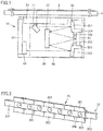
- Fig. 1 is a schematic cross-sectional view of an image reading apparatus according to a first embodiment. With reference to Fig. 1 , an image reading apparatus 10 according to the first embodiment will be described.
- image reading apparatus 10 emits light from a light source 20 to an original document 2 placed on a platen glass 1 as a subject to be read, and receives a reflection of light from the original document by a light receiving unit 40 which converts the received reflection of light photoelectrically to thus read an image.
- Image reading apparatus 10 comprises light source 20, light receiving unit 40, an optical system 30, and a housing 60.
- Light source 20 emits light to a subject to be read in a main scanning direction (a direction perpendicular to the plane of Fig. 1 ).
- Light source 20 can for example be an illumination unit using an LED or the like.
- Light receiving unit 40 receives light reflected by original document 2. Light receiving unit 40 photoelectrically converts the received light. Light receiving unit 40 can be an image pickup device such as a semiconductor sensor or the like. Light receiving unit 40 is mounted on a circuit board 41. Circuit board 41 is provided with a signal processing circuit or the like to process a photoelectrically converted signal.
- Optical system 30 images the light reflected by original document 2 and guides it to light receiving unit 40.
- Optical system 30 includes a plurality of reflector mirrors 31, 32, 33 for reflecting the light reflected by the original document, and an optical element 35 for imaging the light reflected by original document 2.
- the plurality of reflector mirrors 31, 32, 33 When viewed in the main scanning direction, the plurality of reflector mirrors 31, 32, 33 are aligned in a sub-scanning direction (a rightward/leftward direction in Fig. 1 ).
- the plurality of reflector mirrors 31, 32, 33 can for example be planar reflector mirrors.
- reflector mirror 31 has an upper end side inclined in a direction away from reflector mirror 32 with respect to the vertical direction.
- Reflector mirrors 32, 33 are disposed in parallel in the main scanning direction and the vertical direction, for example. Reflector mirrors 32 and 33 face each other in the sub-scanning direction.
- Optical element 35 includes a lens portion and a connecting portion 353.
- the lens portion includes a first lens portion 351 and a second lens portion 352.
- First lens portion 351 and second lens portion 352 are aligned in a direction corresponding to the sub-scanning direction. Specifically, first lens portion 351 and second lens portion 352 are aligned in the vertical direction, for example.
- Connecting portion 353 connects first lens portion 351 and second lens portion 352. Specifically, connecting portion 353 connects a lower end portion of first lens portion 351 and an upper end portion of second lens portion 352. Connecting portion 353 is in the form of a plate. Connecting portion 353 is disposed parallel to the main scanning direction and the vertical direction.
- Optical element 35 is held by reflector mirror 33. More specifically, optical element 35 is bonded at a back surface side of connecting portion 353 of optical element 35. Connecting portion 353 is fixed to reflector mirror 33, which is located on a front side in a direction in which light incident toward connecting portion 353 travels.
- optical element 35 and reflector mirror 33 are aligned in the vertical direction. This can reduce or prevent adhesion of a vertically falling foreign matter to optical element 35 and reflector mirror 33.
- Optical element 35 is a reflective imaging member.
- Optical element 35 is composed of a resin member.
- First lens portion 351 and second lens portion 352 constitute an imaging system for imaging the light reflected by an original document.
- the light reflected by original document 2 is reflected by reflector mirror 31 toward first lens portion 351 of optical element 35.
- the light reflected toward first lens portion 351 and incident on first lens portion 351 is reflected toward reflector mirror 32 while being reduced by first lens portion 351.
- the light reflected toward reflector mirror 32 is limited by a later-described opening 356 (see Fig. 3 ) provided in connecting portion 353, and is thus incident on reflector mirror 33.
- the light incident on reflector mirror 33 is reflected and passes through opening 356 and thus travels toward reflector mirror 32.
- the light incident on reflector mirror 32 is reflected toward second lens portion 352.
- the light reflected toward second lens portion 352 and incident on second lens portion 352 is reflected toward light receiving unit 40 while being reduced by second lens portion 352.
- Housing 60 accommodates optical system 30 therein.
- Housing 60 is configured to be movable in the sub-scanning direction (a direction indicated in Fig. 1 by an arrow DR1).
- Image information of original document 2 can be read by moving housing 60 in the sub-scanning direction and guiding the light that is reflected from original document 2 to light receiving unit 40 by optical system 30, as described above.
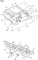
- Fig. 2 is a perspective view showing a front side of a portion of the optical system included in the image reading apparatus shown in Fig. 1 .
- Fig. 3 is a perspective view showing a rear side of a portion of the optical system included in the image reading apparatus shown in Fig. 1 .
- optical system 30 includes a portion in which optical element 35 is held by and integrated with reflector mirror 33.
- Optical element 35 extends in a direction corresponding to the main scanning direction.
- Optical element 35 has an elongate shape.
- Optical element 35 includes a plurality of first lens portions 351 and a plurality of second lens portions 352 as a plurality of lens portions.
- the plurality of first lens portions 351 are disposed in a row.
- the plurality of first lens portions 351 are aligned in a direction corresponding to the main scanning direction.
- the plurality of second lens portions 352 are disposed in a row in a direction parallel to the direction in which the plurality of first lens portions 351 are aligned.
- the plurality of second lens portions 352 are aligned in a direction corresponding to the main scanning direction.
- the plurality of second lens portions 352 are each disposed to be associated with one of the plurality of first lens portions 351.
- First lens portion 351 and second lens portion 352 associated with each other are aligned in a direction corresponding to the sub-scanning direction (in the vertical direction in the present embodiment).
- Connecting portion 353 has a plurality of openings 356.
- the plurality of openings 356 are aligned in a direction corresponding to the main scanning direction.
- the plurality of openings 356 are each disposed between an associated first lens portion 351 and an associated second lens portion 352.
- the plurality of openings 356 each pass light which is reduced and thus reflected by an associated first lens portion 351 and reflected by reflector mirror 32.
- Opening 356 limits the light reflected by reflector mirror 32 and traveling toward light receiving unit 40.
- Opening 356 is provided to have a diameter reduced toward reflector mirror 33.
- optical element 35 held at reflector mirror 33 that has opening 356 allows a position of a stop for limiting light to be determined with precision.
- reflector mirror 33 is located on the front side relative to connecting portion 353 in the direction in which light incident toward connecting portion 353 travels, and reflects light having passed through opening 356, and opening 356 is used as a reflective aperture, a space required for ensuring an optical path can be reduced.
- Optical element 35 further includes a first wall portion 354 and a second wall portion 355.
- First wall portion 354 is connected to a lower end portion of the plurality of first lens portions 351.
- First wall portion 354 projects toward a side opposite to reflector mirror 32 with first lens portion 351 interposed.
- First wall portion 354 is in the form of a plate.
- First wall portion 354 extends in a direction corresponding to the main scanning direction.
- Second wall portion 355 is connected to an upper end portion of the plurality of second lens portions 352. Second wall portion 355 projects toward a side opposite to reflector mirror 32 with second lens portion 352 interposed. Second wall portion 355 is in the form of a plate. Second wall portion 355 is disposed parallel to first wall portion 354 and extends in a direction corresponding to the main scanning direction. Second wall portion 355 is spaced from first wall portion 354 in a direction corresponding to the sub-scanning direction.
- the plurality of first lens portions 351, the plurality of second lens portions 352, connecting portion 353, first wall portion 354, and second wall portion 355 are integrally molded by, for example, injection-molding using a resin member.
- Reflector mirror 33 is disposed between first wall portion 354 and second wall portion 355.
- Reflector mirror 33 is in the form of a plate.
- Reflector mirror 33 extends in a direction corresponding to the main scanning direction.
- Reflector mirror 33 is fixed to connecting portion 353 at a side opposite to reflector mirror 32 with connecting portion 353 interposed.
- Reflector mirror 33 has protruding portions 331 and 332 protruding from optical element 35. More specifically, protruding portions 331 and 332 protrude from optical element 35 in a direction corresponding to the main scanning direction. Protruding portions 331 and 332 are held by a holding portion (not shown) provided in housing 60. In this manner, while reflector mirror 33 is held by housing 60, optical element 35 is held by reflector mirror 33, and optical element 35 can thus be positioned with precision. Further, deflection of optical element 35 and reflector mirror 33 when they are assembled can be suppressed.
- Image reading apparatus 10 further comprises a pressing member 50 that presses reflector mirror 33 toward optical element 35.
- Pressing member 50 is disposed on a side opposite to a path of light reflected by a reflecting surface 33a of reflector mirror 33 (see Fig. 1 ). Pressing member 50 thus disposed can be prevented from interfering with the optical path.
- Pressing member 50 includes a leaf spring portion 51 serving as a biasing portion, and first and second pinching portions 52 and 53 serving as an attachment portion.
- Leaf spring portion 51 extends in a direction corresponding to the sub-scanning direction.
- Leaf spring portion 51 in an attached state in which pressing member 50 is attached to optical element 35, is biased so as to press reflector mirror 33 against connecting portion 353.
- First and second pinching portions 52 and 53 are provided at opposite ends of leaf spring portion 51. First and second pinching portions 52 and 53 are biased toward each other.
- Reflector mirror 33 is disposed between first wall portion 354 and second wall portion 355 and in that condition first wall portion 354 and second wall portion 355 are inserted between first pinching portion 52 and second pinching portion 53 to attach pressing member 50 to optical element 35.
- leaf spring portion 51 exerts a biasing force to press reflector mirror 33 toward connecting portion 353.
- Optical element 35 is thus firmly fixed to reflector mirror 33.
- image reading apparatus 10 has a configuration in which optical element 35 of resin disposed adjacent to reflector mirror 33 of glass and imaging the light reflected by a subject to be read is held by reflector mirror 33.
- optical element 35 of resin lower rigidity than glass by reflector mirror 33 of glass high in rigidity and configured with high precision, warpage of optical element 35 per se and deflection thereof when it is assembled can be suppressed.
- the optical element can thus be positioned with high precision in a simple configuration.
- reflector mirror 33 that is a planar reflector mirror allows optical element 35 to follow a plane of high precision and thus be positioned with higher precision.
- optical element 35 that is of a reflective type severer against surface shape error than a transmissive type, as has been described above, is held on reflector mirror 33, the optical element can be positioned with high precision more effectively.
- optical element 35 even when optical element 35 extends in the longitudinal direction and tends to warp, optical element 35 with a plurality of lens portions and the like formed integrally, that is held on reflector mirror 33, can be positioned with high precision more effectively.
- pressing member 50 may be configured in first and second exemplary variations as described below.
- Fig. 4 is a schematic cross-sectional view for illustrating a first exemplary variation of a pressing member shown in Fig. 3 .
- Fig. 5 is a perspective view for illustrating the first exemplary variation of the pressing member shown in Fig. 3 .
- a pressing member 50A according to the first exemplary variation will be described.
- pressing member 50A has a plate portion 51A, a first hook portion 52A and a second hook portion 53A serving as an attachment portion, a leaf spring portion 54 serving as a biasing portion, and an engaging portion 55.
- Plate portion 51A extends in a direction corresponding to the sub-scanning direction. Plate portion 51A bridges first wall portion 354 and second wall portion 355. First hook portion 52A and second hook portion 53A are provided at opposite ends of plate portion 51A. First hook portion 52A is configured to be capable of being hooked on first wall portion 354. Second hook portion 53A is configured to be capable of being hooked on second wall portion 355.
- Leaf spring portion 54 is provided at a midsection of plate portion 51A.
- Leaf spring portion 54 projects in the main scanning direction of plate portion 51A and is bent in a direction away from plate portion 51A.
- Leaf spring portion 54 is folded back so that in an attached state in which pressing member 50A is attached to optical element 35 reflector mirror 33 is biased toward connecting portion 353.
- Reflector mirror 33 is disposed between first wall portion 354 and second wall portion 355 and in that condition first hook portion 52A is hooked on first wall portion 354 and second hook portion 53A is hooked on second wall portion 355 to attach pressing member 50 to optical element 35.
- leaf spring portion 54 exerts a biasing force to press reflector mirror 33 toward connecting portion 353.
- Optical element 35 is thus firmly fixed to reflector mirror 33.
- Engaging portion 55 is configured to be capable of engaging an engaged portion provided to housing 60. By attaching pressing member 50 to optical element 35, and in that condition, attaching engaging portion 55 to the engaged portion, reflector mirror 33 and optical element 35 can be held more stably.
- Fig. 6 is a perspective view for illustrating a second exemplary variation of the pressing member shown in Fig. 4 .
- a pressing member 50B according to the second exemplary variation will be described.
- pressing member 50B is configured to be insertable into connecting portion 353.
- Pressing member 50B has plate portion 51A, and first hook portion 52A and second hook portion 53A.
- Plate portion 51A has a rectangular shape. Plate portion 51A is disposed between first lens portion 351 and second lens portion 352 in a direction corresponding to the sub-scanning direction. Plate portion 51A, in a state where pressing member 50B is attached, abuts against connecting portion 353 at a side opposite to reflector mirror 33 with connecting portion 353 interposed.
- First hook portion 52A and second hook portion 53A are provided at opposite ends of plate portion 51A.
- First hook portion 52A is configured to be insertable into an insertion hole 353a provided through connecting portion 353.
- First hook portion 52A has a first claw portion 57.
- First claw portion 57 is configured to be capable of catching a main surface of reflector mirror 33 located on a side opposite to a main surface of reflector mirror 33 facing connecting portion 353.
- Second hook portion 53A faces first hook portion 52A in a direction corresponding to the sub-scanning direction. Second hook portion 53A is configured to be insertable into an insertion hole 353b provided through connecting portion 353. Insertion hole 353b and insertion hole 353a are aligned in a direction corresponding to the sub-scanning direction. Second hook portion 53A has a second claw portion 58. Second claw portion 58 is configured to be capable of catching a main surface of reflector mirror 33 located on a side opposite to a main surface of reflector mirror 33 facing connecting portion 353.
- First hook portion 52A is inserted through insertion hole 353a and second hook portion 53A is inserted into insertion hole 353b and in that condition, first claw portion 57 and second claw portion 58 catch the reflector mirror, so that a pressing force acts between plate portion 51A and first and second claw portions 57 and 58.
- pressing member 50B presses reflector mirror 33 toward connecting portion 353.
- optical element 35 is firmly fixed to reflector mirror 33.
- pressing member 50A according to the first exemplary variation, or pressing member 50B according to the second exemplary variation deflection can be suppressed even when a thermal expansion difference occurs between optical element 35 of resin and reflector mirror 33 of glass in use.
- Fig. 7 is a schematic diagram of an image reading apparatus according to a second embodiment. With reference to Fig. 7 , an image reading apparatus 10A according to the second embodiment will be described.
- image reading apparatus 10A is different in that an optical system 30A is configured using a transmissive optical element 35A.
- the remainder in configurations is substantially the same.
- Optical system 30A images the light reflected by original document 2 and guides it to light receiving unit 40.
- Optical system 30A includes a plurality of reflector mirrors 31, 32, 33, 34 for reflecting the light reflected by the original document, and optical element 35A for imaging the light reflected by original document 2.
- Reflector mirrors 31, 32, 33 are aligned in the sub-scanning direction.
- Reflector mirrors 33 and 34 are aligned in the vertical direction.
- Optical element 35A includes a lens portion and connecting portion 353.
- the lens portion includes first lens portion 351 and second lens portion 352.
- First lens portion 351 and second lens portion 352 are aligned in a direction corresponding to the sub-scanning direction. Specifically, first lens portion 351 and second lens portion 352 are aligned in the vertical direction, for example.
- Connecting portion 353 connects first lens portion 351 and second lens portion 352. Specifically, connecting portion 353 connects a lower end portion of first lens portion 351 and an upper end portion of second lens portion 352. Connecting portion 353 is in the form of a plate. Connecting portion 353 is disposed parallel to the main scanning direction and the vertical direction.
- Optical element 35A is held by reflector mirror 33. More specifically, optical element 35A is bonded at a back surface side of connecting portion 353 of optical element 35A. Connecting portion 353 is fixed to reflector mirror 33, which is located on a front side in a direction in which light incident toward connecting portion 353 travels.
- Optical element 35A is a transmissive imaging member.
- Optical element 35A is composed of a resin member.
- First lens portion 351 and second lens portion 352 constitute an imaging system for imaging the light reflected by an original document.
- the light reflected by original document 2 is reflected by reflector mirror 31 toward first lens portion 351 of optical element 35A.
- the light reflected toward first lens portion 351 and incident on first lens portion 351 travels toward reflector mirror 32 while being reduced by first lens portion 351.
- the light transmitted through first lens portion 351 and incident on reflector mirror 32 is reflected toward reflector mirror 33.
- the light reflected toward reflector mirror 33 is limited by opening 356 provided in connecting portion 353, and is thus incident on reflector mirror 32.
- the light incident on reflector mirror 32 is reflected and passes through opening 356 and thus travels toward reflector mirror 34.
- the light incident on reflector mirror 34 is reflected toward second lens portion 352.
- the light incident on second lens portion 352 travels toward light receiving unit 40 while being reduced by second lens portion 352.
- image reading apparatus 10A according to the second embodiment has a configuration in which optical element 35A of resin disposed adjacent to reflector mirror 33 of glass and imaging the light reflected by a subject to be read is held by reflector mirror 33.
- image reading apparatus 10A according to the second embodiment can also provide an effect substantially equivalent to that of the first embodiment.
- the number of reflector mirrors included in the optical system and that of optical elements are not limited to those described in the first or second embodiment, and can be changed, as appropriate, within a range which does not depart from the gist of the present invention insofar as a reflection of light from original document 2 can be guided to the light receiving unit.
- the lens portion includes a plurality of first lens portions 351 and a plurality of second lens portions 352
- this is not exclusive, and it is sufficient that the lens portion includes one of the plurality of first lens portions 351 and the plurality of second lens portions 352.
- one of the plurality of first lens portions 351 and the plurality of second lens portions 352 is fixed to reflector mirror 33.
- first lens portions 351 and the plurality of second lens portions 352 are integrally formed by injection molding
- each of first lens portions 351 and each of second lens portions 352 may be formed separately insofar as they are fixed to the optical element.
- protruding portions 331 and 332 of reflector mirror 33 protrude from optical element 35 in a direction corresponding to the main scanning direction
- this is not exclusive, and they may protrude in a direction traversing the direction corresponding to the main scanning direction in a range in which they do not interfere with the light guided to light receiving unit 40.
- the protruding portions are held by a holding portion provided in housing 60.
Landscapes
- Engineering & Computer Science (AREA)
- Multimedia (AREA)
- Signal Processing (AREA)
- Physics & Mathematics (AREA)
- Optics & Photonics (AREA)
- Facsimile Scanning Arrangements (AREA)
- Facsimile Heads (AREA)
- Lenses (AREA)
- Lens Barrels (AREA)
- Light Sources And Details Of Projection-Printing Devices (AREA)
- Mounting And Adjusting Of Optical Elements (AREA)
Abstract
Description
- The present invention relates to an image reading apparatus that reads an image of a subject to be read to obtain an image signal.
- As an example of a conventional image reading apparatus, there exists what is called a CIS sensor (contact image sensor) using a gradient index lens array. The CIS image sensor irradiates an original document with the light from an LED and images a reflection of light from the original document by a lens array referred to as SELFOC (registered trademark) producing an erect real image to thus read image information.
- The CIS image sensor using the SELFOC (registered trademark) lens array is called a pupil-dividing optical system and is an optical system that collects light from a plurality of lenses for one point. Therefore, when the original document is positionally slightly changed, an image from an adjacent lens is offset and thus overlaps, resulting in a narrowed depth of field.
- Accordingly, as an image reading apparatus capable of making depth of field greater, Japanese Laid-Open Patent Publication No.
2009-244500 - An image reading apparatus allowing an optical element to be positioned with high precision and constantly keeping a relative position in a direction of depth in a longitudinal direction of an imaging optical system without causing self-weight deflection or warpage, is disclosed for example in Japanese Laid-Open Patent Publication No.
2015-159444 2015-159444 - A holding mechanism capable of holding a light emitting element array substrate with high precision is disclosed in, for example, Japanese Laid-Open Patent Publication No.
2001-250989 2001-250989 - However, the image reading apparatus disclosed in Japanese Laid-Open Patent Publication No.
2015-159444 - The holding mechanism disclosed in Japanese Laid-Open Patent Publication No.
2001-250989 - The present invention has been made in view of the above issues, and an object thereof is to provide an image reading apparatus allowing an optical element to be positioned with high precision in a simple configuration.
- To achieve at least one of the abovementioned objects, according to an aspect of the present invention, an image reading apparatus reflecting one aspect of the present invention comprises: a light source that emits light in a main scanning direction to a subject to be read; a light receiving unit that receives light reflected by the subject to be read; and an optical system that images the light reflected by the subject to be read and guides the light to the light receiving unit, the optical system including a reflector mirror that reflects the light reflected by the subject to be read, and an optical element that is disposed adjacent to the reflector mirror and images the light reflected by the subject to be read, the optical element being held by the reflector mirror.
- Preferably, the image reading apparatus according to the present invention further comprises a pressing member that presses the reflector mirror toward the optical element, and the pressing member is used to fix the optical element and the reflector mirror.
- Preferably, the image reading apparatus according to the present invention further comprises a housing that houses the optical system therein. In that case, the pressing member may have an engaging portion that engages the housing. Furthermore, in that case, preferably, by the engaging portion engaging the housing, the pressing member is supported by the housing.
- In the image reading apparatus according to the present invention, preferably, the reflector mirror has a reflecting surface for folding back an optical path, and the pressing member is disposed on a side opposite to the optical path with the reflecting surface interposed.
- Preferably, the image reading apparatus according to the present invention further comprises a housing that houses the optical system. In that case, the reflector mirror may have a protruding portion protruding from the optical element. Furthermore, in that case, preferably, the protruding portion is held by the housing.
- In the image reading apparatus according to the present invention, the optical element may include a lens portion that images the light reflected by the subject to be read, and a connecting portion. In that case, the lens portion may have a first lens portion and a second lens portion aligned in a direction corresponding to a sub-scanning direction. Preferably, the connecting portion connects the first lens portion and the second lens portion. Furthermore, preferably, the reflector mirror is disposed between the first lens portion and the second lens portion in a direction corresponding to the sub-scanning direction, and the connecting portion is attached to the reflector mirror.
- In the image reading apparatus according to the present invention, the optical element may include a lens portion that images the light reflected by the subject to be read, and a traversing portion connected to the lens portion to be positioned in a direction corresponding to the sub-scanning direction with respect to the lens portion, and provided to be capable of traversing light traveling toward the light receiving unit. In that case, preferably, the traversing portion has an opening that limits the light traveling toward the light receiving unit.
- In the image reading apparatus according to the present invention, preferably, the reflector mirror is located on a front side relative to the traversing portion in a direction in which light incident toward the traversing portion travels, and the reflector mirror reflects light having passed through the opening.
- In the image reading apparatus according to the present invention, the optical element may have a lens portion that images the light reflected by the subject to be read, and the lens portion and the reflector mirror may be aligned in a vertical direction.
- In the image reading apparatus according to the present invention, the optical element is a reflective imaging member.
- In the image reading apparatus according to the present invention, the optical element may include a plurality of lens portions that image the light reflected by the subject to be read and are aligned in a direction corresponding to the main scanning direction. In that case, preferably, the plurality of lens portions are integrally formed.
- The advantages and features provided by one or more embodiments of the invention will become more fully understood from the detailed description given hereinbelow and the appended drawings which are given by way of illustration only, and thus are not intended as a definition of the limits of the present invention.
-
Fig. 1 is a schematic cross-sectional view of an image reading apparatus according to a first embodiment. -
Fig. 2 is a perspective view showing a front side of a portion of an optical system included in the image reading apparatus shown inFig. 1 . -
Fig. 3 is a perspective view showing a rear side of a portion of the optical system included in the image reading apparatus shown inFig. 1 . -
Fig. 4 is a schematic cross-sectional view for illustrating a first exemplary variation of a pressing member shown inFig. 3 . -
Fig. 5 is a perspective view for illustrating the first exemplary variation of the pressing member shown inFig. 3 . -
Fig. 6 is a perspective view for illustrating a second exemplary variation of the pressing member shown inFig. 4 . -
Fig. 7 is a schematic diagram of an image reading apparatus according to a second embodiment. Detailed Description of Embodiments - Hereinafter, one or more embodiments of the present invention will be described with reference to the drawings. However, the scope of the invention is not limited to the disclosed embodiments. In the following embodiments, identical or common components are identically denoted in the figures and will not be described repeatedly.
-
Fig. 1 is a schematic cross-sectional view of an image reading apparatus according to a first embodiment. With reference toFig. 1 , animage reading apparatus 10 according to the first embodiment will be described. - As shown in
Fig. 1 ,image reading apparatus 10 according to the first embodiment emits light from alight source 20 to anoriginal document 2 placed on aplaten glass 1 as a subject to be read, and receives a reflection of light from the original document by alight receiving unit 40 which converts the received reflection of light photoelectrically to thus read an image.Image reading apparatus 10 compriseslight source 20,light receiving unit 40, anoptical system 30, and ahousing 60. -
Light source 20 emits light to a subject to be read in a main scanning direction (a direction perpendicular to the plane ofFig. 1 ).Light source 20 can for example be an illumination unit using an LED or the like. - Light receiving
unit 40 receives light reflected byoriginal document 2.Light receiving unit 40 photoelectrically converts the received light. Light receivingunit 40 can be an image pickup device such as a semiconductor sensor or the like. Light receivingunit 40 is mounted on acircuit board 41.Circuit board 41 is provided with a signal processing circuit or the like to process a photoelectrically converted signal. -
Optical system 30 images the light reflected byoriginal document 2 and guides it to light receivingunit 40.Optical system 30 includes a plurality of reflector mirrors 31, 32, 33 for reflecting the light reflected by the original document, and anoptical element 35 for imaging the light reflected byoriginal document 2. - When viewed in the main scanning direction, the plurality of reflector mirrors 31, 32, 33 are aligned in a sub-scanning direction (a rightward/leftward direction in
Fig. 1 ). The plurality of reflector mirrors 31, 32, 33 can for example be planar reflector mirrors. For example,reflector mirror 31 has an upper end side inclined in a direction away fromreflector mirror 32 with respect to the vertical direction. Reflector mirrors 32, 33 are disposed in parallel in the main scanning direction and the vertical direction, for example. Reflector mirrors 32 and 33 face each other in the sub-scanning direction. -
Optical element 35 includes a lens portion and a connectingportion 353. The lens portion includes afirst lens portion 351 and asecond lens portion 352.First lens portion 351 andsecond lens portion 352 are aligned in a direction corresponding to the sub-scanning direction. Specifically,first lens portion 351 andsecond lens portion 352 are aligned in the vertical direction, for example. - Connecting
portion 353 connectsfirst lens portion 351 andsecond lens portion 352. Specifically, connectingportion 353 connects a lower end portion offirst lens portion 351 and an upper end portion ofsecond lens portion 352. Connectingportion 353 is in the form of a plate. Connectingportion 353 is disposed parallel to the main scanning direction and the vertical direction. -
Optical element 35 is held byreflector mirror 33. More specifically,optical element 35 is bonded at a back surface side of connectingportion 353 ofoptical element 35. Connectingportion 353 is fixed toreflector mirror 33, which is located on a front side in a direction in which light incident toward connectingportion 353 travels. - The lens portion of
optical element 35 andreflector mirror 33 are aligned in the vertical direction. This can reduce or prevent adhesion of a vertically falling foreign matter tooptical element 35 andreflector mirror 33. -
Optical element 35 is a reflective imaging member.Optical element 35 is composed of a resin member.First lens portion 351 andsecond lens portion 352 constitute an imaging system for imaging the light reflected by an original document. - The light reflected by
original document 2 is reflected byreflector mirror 31 towardfirst lens portion 351 ofoptical element 35. The light reflected towardfirst lens portion 351 and incident onfirst lens portion 351 is reflected towardreflector mirror 32 while being reduced byfirst lens portion 351. - The light reflected toward
reflector mirror 32 is limited by a later-described opening 356 (seeFig. 3 ) provided in connectingportion 353, and is thus incident onreflector mirror 33. The light incident onreflector mirror 33 is reflected and passes throughopening 356 and thus travels towardreflector mirror 32. - The light incident on
reflector mirror 32 is reflected towardsecond lens portion 352. The light reflected towardsecond lens portion 352 and incident onsecond lens portion 352 is reflected toward light receivingunit 40 while being reduced bysecond lens portion 352. -
Housing 60 accommodatesoptical system 30 therein.Housing 60 is configured to be movable in the sub-scanning direction (a direction indicated inFig. 1 by an arrow DR1). Image information oforiginal document 2 can be read by movinghousing 60 in the sub-scanning direction and guiding the light that is reflected fromoriginal document 2 to light receivingunit 40 byoptical system 30, as described above. -
Fig. 2 is a perspective view showing a front side of a portion of the optical system included in the image reading apparatus shown inFig. 1 .Fig. 3 is a perspective view showing a rear side of a portion of the optical system included in the image reading apparatus shown inFig. 1 . With reference toFigs. 2 and3 , a specific shape ofoptical element 35 and a structure fixingoptical element 35 andreflector mirror 33 will be described. - As shown in
Figs. 2 and3 ,optical system 30 includes a portion in whichoptical element 35 is held by and integrated withreflector mirror 33.Optical element 35 extends in a direction corresponding to the main scanning direction.Optical element 35 has an elongate shape. -
Optical element 35 includes a plurality offirst lens portions 351 and a plurality ofsecond lens portions 352 as a plurality of lens portions. The plurality offirst lens portions 351 are disposed in a row. For example, the plurality offirst lens portions 351 are aligned in a direction corresponding to the main scanning direction. - The plurality of
second lens portions 352 are disposed in a row in a direction parallel to the direction in which the plurality offirst lens portions 351 are aligned. The plurality ofsecond lens portions 352 are aligned in a direction corresponding to the main scanning direction. The plurality ofsecond lens portions 352 are each disposed to be associated with one of the plurality offirst lens portions 351.First lens portion 351 andsecond lens portion 352 associated with each other are aligned in a direction corresponding to the sub-scanning direction (in the vertical direction in the present embodiment). - The plurality of
first lens portions 351 and the plurality ofsecond lens portions 352 are connected by connectingportion 353. Connectingportion 353 has a plurality ofopenings 356. The plurality ofopenings 356 are aligned in a direction corresponding to the main scanning direction. - The plurality of
openings 356 are each disposed between an associatedfirst lens portion 351 and an associatedsecond lens portion 352. The plurality ofopenings 356 each pass light which is reduced and thus reflected by an associatedfirst lens portion 351 and reflected byreflector mirror 32. Opening 356 limits the light reflected byreflector mirror 32 and traveling toward light receivingunit 40.Opening 356 is provided to have a diameter reduced towardreflector mirror 33. - As described above,
optical element 35 held atreflector mirror 33 that has opening 356 allows a position of a stop for limiting light to be determined with precision. - Furthermore, as
reflector mirror 33 is located on the front side relative to connectingportion 353 in the direction in which light incident toward connectingportion 353 travels, and reflects light having passed throughopening 356, andopening 356 is used as a reflective aperture, a space required for ensuring an optical path can be reduced. -
Optical element 35 further includes afirst wall portion 354 and asecond wall portion 355.First wall portion 354 is connected to a lower end portion of the plurality offirst lens portions 351.First wall portion 354 projects toward a side opposite toreflector mirror 32 withfirst lens portion 351 interposed.First wall portion 354 is in the form of a plate.First wall portion 354 extends in a direction corresponding to the main scanning direction. -
Second wall portion 355 is connected to an upper end portion of the plurality ofsecond lens portions 352.Second wall portion 355 projects toward a side opposite toreflector mirror 32 withsecond lens portion 352 interposed.Second wall portion 355 is in the form of a plate.Second wall portion 355 is disposed parallel tofirst wall portion 354 and extends in a direction corresponding to the main scanning direction.Second wall portion 355 is spaced fromfirst wall portion 354 in a direction corresponding to the sub-scanning direction. - The plurality of
first lens portions 351, the plurality ofsecond lens portions 352, connectingportion 353,first wall portion 354, andsecond wall portion 355 are integrally molded by, for example, injection-molding using a resin member. -
Reflector mirror 33 is disposed betweenfirst wall portion 354 andsecond wall portion 355.Reflector mirror 33 is in the form of a plate.Reflector mirror 33 extends in a direction corresponding to the main scanning direction.Reflector mirror 33 is fixed to connectingportion 353 at a side opposite toreflector mirror 32 with connectingportion 353 interposed. -
Reflector mirror 33 has protrudingportions optical element 35. More specifically, protrudingportions optical element 35 in a direction corresponding to the main scanning direction. Protrudingportions housing 60. In this manner, whilereflector mirror 33 is held byhousing 60,optical element 35 is held byreflector mirror 33, andoptical element 35 can thus be positioned with precision. Further, deflection ofoptical element 35 andreflector mirror 33 when they are assembled can be suppressed. -
Image reading apparatus 10 further comprises a pressingmember 50 that pressesreflector mirror 33 towardoptical element 35. - Pressing
member 50 is disposed on a side opposite to a path of light reflected by a reflectingsurface 33a of reflector mirror 33 (seeFig. 1 ). Pressingmember 50 thus disposed can be prevented from interfering with the optical path. - Pressing
member 50 includes aleaf spring portion 51 serving as a biasing portion, and first andsecond pinching portions Leaf spring portion 51 extends in a direction corresponding to the sub-scanning direction.Leaf spring portion 51, in an attached state in which pressingmember 50 is attached tooptical element 35, is biased so as to pressreflector mirror 33 against connectingportion 353. - First and
second pinching portions leaf spring portion 51. First andsecond pinching portions -
Reflector mirror 33 is disposed betweenfirst wall portion 354 andsecond wall portion 355 and in that conditionfirst wall portion 354 andsecond wall portion 355 are inserted between first pinchingportion 52 and second pinchingportion 53 to attach pressingmember 50 tooptical element 35. On this occasion,leaf spring portion 51 exerts a biasing force to pressreflector mirror 33 toward connectingportion 353.Optical element 35 is thus firmly fixed toreflector mirror 33. - Thus,
image reading apparatus 10 according to the first embodiment has a configuration in whichoptical element 35 of resin disposed adjacent toreflector mirror 33 of glass and imaging the light reflected by a subject to be read is held byreflector mirror 33. By thus holdingoptical element 35 of resin lower rigidity than glass byreflector mirror 33 of glass high in rigidity and configured with high precision, warpage ofoptical element 35 per se and deflection thereof when it is assembled can be suppressed. The optical element can thus be positioned with high precision in a simple configuration. Furthermore,reflector mirror 33 that is a planar reflector mirror allowsoptical element 35 to follow a plane of high precision and thus be positioned with higher precision. - In addition, when
optical element 35 that is of a reflective type severer against surface shape error than a transmissive type, as has been described above, is held onreflector mirror 33, the optical element can be positioned with high precision more effectively. - Furthermore, even when
optical element 35 extends in the longitudinal direction and tends to warp,optical element 35 with a plurality of lens portions and the like formed integrally, that is held onreflector mirror 33, can be positioned with high precision more effectively. - Note that pressing
member 50 may be configured in first and second exemplary variations as described below. -
Fig. 4 is a schematic cross-sectional view for illustrating a first exemplary variation of a pressing member shown inFig. 3 .Fig. 5 is a perspective view for illustrating the first exemplary variation of the pressing member shown inFig. 3 . With reference toFig. 4 andFig. 5 , a pressingmember 50A according to the first exemplary variation will be described. - As shown in
Figs. 4 and5 , pressingmember 50A has aplate portion 51A, afirst hook portion 52A and asecond hook portion 53A serving as an attachment portion, aleaf spring portion 54 serving as a biasing portion, and an engagingportion 55. -
Plate portion 51A extends in a direction corresponding to the sub-scanning direction.Plate portion 51A bridgesfirst wall portion 354 andsecond wall portion 355.First hook portion 52A andsecond hook portion 53A are provided at opposite ends ofplate portion 51A.First hook portion 52A is configured to be capable of being hooked onfirst wall portion 354.Second hook portion 53A is configured to be capable of being hooked onsecond wall portion 355. -
Leaf spring portion 54 is provided at a midsection ofplate portion 51A.Leaf spring portion 54 projects in the main scanning direction ofplate portion 51A and is bent in a direction away fromplate portion 51A.Leaf spring portion 54 is folded back so that in an attached state in which pressingmember 50A is attached tooptical element 35reflector mirror 33 is biased toward connectingportion 353. -
Reflector mirror 33 is disposed betweenfirst wall portion 354 andsecond wall portion 355 and in that conditionfirst hook portion 52A is hooked onfirst wall portion 354 andsecond hook portion 53A is hooked onsecond wall portion 355 to attach pressingmember 50 tooptical element 35. On this occasion,leaf spring portion 54 exerts a biasing force to pressreflector mirror 33 toward connectingportion 353.Optical element 35 is thus firmly fixed toreflector mirror 33. - Engaging
portion 55 is configured to be capable of engaging an engaged portion provided tohousing 60. By attaching pressingmember 50 tooptical element 35, and in that condition, attaching engagingportion 55 to the engaged portion,reflector mirror 33 andoptical element 35 can be held more stably. -
Fig. 6 is a perspective view for illustrating a second exemplary variation of the pressing member shown inFig. 4 . With reference toFig. 6 , a pressingmember 50B according to the second exemplary variation will be described. - As shown in
Fig. 6 , pressingmember 50B is configured to be insertable into connectingportion 353. Pressingmember 50B hasplate portion 51A, andfirst hook portion 52A andsecond hook portion 53A. -
Plate portion 51A has a rectangular shape.Plate portion 51A is disposed betweenfirst lens portion 351 andsecond lens portion 352 in a direction corresponding to the sub-scanning direction.Plate portion 51A, in a state where pressingmember 50B is attached, abuts against connectingportion 353 at a side opposite toreflector mirror 33 with connectingportion 353 interposed. -
First hook portion 52A andsecond hook portion 53A are provided at opposite ends ofplate portion 51A.First hook portion 52A is configured to be insertable into an insertion hole 353a provided through connectingportion 353.First hook portion 52A has afirst claw portion 57.First claw portion 57 is configured to be capable of catching a main surface ofreflector mirror 33 located on a side opposite to a main surface ofreflector mirror 33 facing connectingportion 353. -
Second hook portion 53A facesfirst hook portion 52A in a direction corresponding to the sub-scanning direction.Second hook portion 53A is configured to be insertable into an insertion hole 353b provided through connectingportion 353. Insertion hole 353b and insertion hole 353a are aligned in a direction corresponding to the sub-scanning direction.Second hook portion 53A has asecond claw portion 58.Second claw portion 58 is configured to be capable of catching a main surface ofreflector mirror 33 located on a side opposite to a main surface ofreflector mirror 33 facing connectingportion 353. -
First hook portion 52A is inserted through insertion hole 353a andsecond hook portion 53A is inserted into insertion hole 353b and in that condition,first claw portion 57 andsecond claw portion 58 catch the reflector mirror, so that a pressing force acts betweenplate portion 51A and first andsecond claw portions member 50B pressesreflector mirror 33 toward connectingportion 353. As a result,optical element 35 is firmly fixed toreflector mirror 33. - As described above, by firmly fixing
optical element 35 toreflector mirror 33 by using pressingmember 50, pressingmember 50A according to the first exemplary variation, or pressingmember 50B according to the second exemplary variation, deflection can be suppressed even when a thermal expansion difference occurs betweenoptical element 35 of resin andreflector mirror 33 of glass in use. -
Fig. 7 is a schematic diagram of an image reading apparatus according to a second embodiment. With reference toFig. 7 , animage reading apparatus 10A according to the second embodiment will be described. - As shown in
Fig. 7 ,image reading apparatus 10A according to the second embodiment is different in that anoptical system 30A is configured using a transmissiveoptical element 35A. The remainder in configurations is substantially the same. -
Optical system 30A images the light reflected byoriginal document 2 and guides it to light receivingunit 40.Optical system 30A includes a plurality of reflector mirrors 31, 32, 33, 34 for reflecting the light reflected by the original document, andoptical element 35A for imaging the light reflected byoriginal document 2. - Reflector mirrors 31, 32, 33 are aligned in the sub-scanning direction. Reflector mirrors 33 and 34 are aligned in the vertical direction.
-
Optical element 35A includes a lens portion and connectingportion 353. The lens portion includesfirst lens portion 351 andsecond lens portion 352.First lens portion 351 andsecond lens portion 352 are aligned in a direction corresponding to the sub-scanning direction. Specifically,first lens portion 351 andsecond lens portion 352 are aligned in the vertical direction, for example. - Connecting
portion 353 connectsfirst lens portion 351 andsecond lens portion 352. Specifically, connectingportion 353 connects a lower end portion offirst lens portion 351 and an upper end portion ofsecond lens portion 352. Connectingportion 353 is in the form of a plate. Connectingportion 353 is disposed parallel to the main scanning direction and the vertical direction. -
Optical element 35A is held byreflector mirror 33. More specifically,optical element 35A is bonded at a back surface side of connectingportion 353 ofoptical element 35A. Connectingportion 353 is fixed toreflector mirror 33, which is located on a front side in a direction in which light incident toward connectingportion 353 travels. -
Optical element 35A is a transmissive imaging member.Optical element 35A is composed of a resin member.First lens portion 351 andsecond lens portion 352 constitute an imaging system for imaging the light reflected by an original document. - The light reflected by
original document 2 is reflected byreflector mirror 31 towardfirst lens portion 351 ofoptical element 35A. The light reflected towardfirst lens portion 351 and incident onfirst lens portion 351 travels towardreflector mirror 32 while being reduced byfirst lens portion 351. - The light transmitted through
first lens portion 351 and incident onreflector mirror 32 is reflected towardreflector mirror 33. The light reflected towardreflector mirror 33 is limited by opening 356 provided in connectingportion 353, and is thus incident onreflector mirror 32. The light incident onreflector mirror 32 is reflected and passes throughopening 356 and thus travels towardreflector mirror 34. - The light incident on
reflector mirror 34 is reflected towardsecond lens portion 352. The light incident onsecond lens portion 352 travels toward light receivingunit 40 while being reduced bysecond lens portion 352. - Thus,
image reading apparatus 10A according to the second embodiment has a configuration in whichoptical element 35A of resin disposed adjacent toreflector mirror 33 of glass and imaging the light reflected by a subject to be read is held byreflector mirror 33. Thusimage reading apparatus 10A according to the second embodiment can also provide an effect substantially equivalent to that of the first embodiment. - Note that the number of reflector mirrors included in the optical system and that of optical elements are not limited to those described in the first or second embodiment, and can be changed, as appropriate, within a range which does not depart from the gist of the present invention insofar as a reflection of light from
original document 2 can be guided to the light receiving unit. - While in the first and second embodiments a case where the lens portion includes a plurality of
first lens portions 351 and a plurality ofsecond lens portions 352 has been described by way of example, this is not exclusive, and it is sufficient that the lens portion includes one of the plurality offirst lens portions 351 and the plurality ofsecond lens portions 352. In that case, one of the plurality offirst lens portions 351 and the plurality ofsecond lens portions 352 is fixed toreflector mirror 33. - While in the first and second embodiments a case where the plurality of
first lens portions 351 and the plurality ofsecond lens portions 352 are integrally formed by injection molding has been described as an example, this is not exclusive, and each offirst lens portions 351 and each ofsecond lens portions 352 may be formed separately insofar as they are fixed to the optical element. - While in the first and second embodiments a case where protruding
portions reflector mirror 33 protrude fromoptical element 35 in a direction corresponding to the main scanning direction has been described as an example, this is not exclusive, and they may protrude in a direction traversing the direction corresponding to the main scanning direction in a range in which they do not interfere with the light guided to light receivingunit 40. In that case also, the protruding portions are held by a holding portion provided inhousing 60. - Although embodiments of the present invention have been described and illustrated in detail, it is clearly understood that the same is by way of illustration and example only and not limitation, the scope of the present invention should be interpreted by terms of the appended claims.
Claims (11)
- An image reading apparatus comprising:a light source (20) that emits light in a main scanning direction to a subject to be read (2);a light receiving unit (40) that receives light reflected by the subject to be read (2); andan optical system (30, 30A) that images the light reflected by the subject to be read (2) and guides the light to the light receiving unit (40),the optical system (30, 30A) including a reflector mirror (33) of glass and an optical element (35, 35A) of resin that is disposed adjacent to the reflector mirror (33) and images the light reflected by the subject to be read (2),the optical element (35, 35A) being held by the reflector mirror (33).
- The image reading apparatus according to claim 1, further comprising a pressing member (50, 50A, 50B) that presses the reflector mirror (33) toward the optical element (35, 35A), wherein the pressing member (50, 50A, 50B) is used to fix the optical element (35, 35A) and the reflector mirror (33).
- The image reading apparatus according to claim 2, further comprising a housing (60) that houses the optical system (30) therein, wherein
the pressing member (50A) has an engaging portion (55) that engages the housing (60), and
by the engaging portion (55) engaging the housing (60), the pressing member (50A) is supported by the housing (60). - The image reading apparatus according to claim 2 or 3, wherein
the reflector mirror (33) has a reflecting surface (33a) for reflecting light, and
the pressing member (50, 50A) is disposed on a side opposite to a path of light reflected by the reflecting surface (33a). - The image reading apparatus according to any one of claims 1 to 4, further comprising a housing (60) that houses the optical system (30, 30A) therein, wherein
the reflector mirror (33) has a protruding portion (331, 332) protruding from the optical element (35, 35A), and
the protruding portion (331, 332) is held by the housing (60). - The image reading apparatus according to any one of claims 1 to 5, wherein
the optical element (35, 35A) includes a lens portion that images the light reflected by the subject to be read (2), and a connecting portion (353),
the lens portion has a first lens portion (351) and a second lens portion (352) aligned in a direction corresponding to a sub-scanning direction,
the connecting portion (353) connects the first lens portion (351) and the second lens portion (352),
the reflector mirror (33) is disposed between the first lens portion (351) and the second lens portion (352) in a direction corresponding to the sub-scanning direction, and
the connecting portion (353) is attached to the reflector mirror (33). - The image reading apparatus according to any one of claims 1 to 6, wherein
the optical element (35, 35A) includes a lens portion that images the light reflected by the subject to be read (2), and a traversing portion (353) connected to the lens portion to be positioned in a direction corresponding to a sub-scanning direction with respect to the lens portion, and provided to be capable of traversing light traveling toward the light receiving unit (40), and
the traversing portion has an opening (356) that limits the light traveling toward the light receiving unit (40). - The image reading apparatus according to claim 7, wherein the reflector mirror (33) is located on a front side relative to the traversing portion (353) in a direction in which light incident toward the traversing portion (353) travels, and the reflector mirror (33) reflects light having passed through the opening (356).
- The image reading apparatus according to any one of claims 1 to 8, wherein
the optical element (35, 35A) has a lens portion that images the light reflected by the subject to be read (2), and
the lens portion and the reflector mirror (33) are aligned in a vertical direction. - The image reading apparatus according to any one of claims 1 to 9, wherein the optical element (35) is a reflective imaging member.
- The image reading apparatus according to any one of claims 1 to 10, wherein
the optical element (35, 35A) includes a plurality of lens portions that image the light reflected by the subject to be read (2) and are aligned in a direction corresponding to the main scanning direction, and
the plurality of lens portions are integrally formed.
Applications Claiming Priority (1)
| Application Number | Priority Date | Filing Date | Title |
|---|---|---|---|
| JP2016218787A JP6889390B2 (en) | 2016-11-09 | 2016-11-09 | Image reader |
Publications (1)
| Publication Number | Publication Date |
|---|---|
| EP3322170A1 true EP3322170A1 (en) | 2018-05-16 |
Family
ID=60301786
Family Applications (1)
| Application Number | Title | Priority Date | Filing Date |
|---|---|---|---|
| EP17200284.2A Withdrawn EP3322170A1 (en) | 2016-11-09 | 2017-11-07 | Image reading apparatus |
Country Status (4)
| Country | Link |
|---|---|
| US (1) | US10462315B2 (en) |
| EP (1) | EP3322170A1 (en) |
| JP (1) | JP6889390B2 (en) |
| CN (1) | CN108063880B (en) |
Citations (4)
| Publication number | Priority date | Publication date | Assignee | Title |
|---|---|---|---|---|
| JP2001250989A (en) | 2000-03-07 | 2001-09-14 | Ricoh Co Ltd | Light emitting element array substrate holding mechanism, optical writing device, image forming device |
| JP2009244500A (en) | 2008-03-31 | 2009-10-22 | Mitsubishi Electric Corp | Image reader |
| EP2166743A1 (en) * | 2007-07-13 | 2010-03-24 | Mitsubishi Electric Corporation | Image-scanning device |
| JP2015159444A (en) | 2014-02-25 | 2015-09-03 | 三菱電機株式会社 | Image reading device |
Family Cites Families (14)
| Publication number | Priority date | Publication date | Assignee | Title |
|---|---|---|---|---|
| JPS5799604A (en) * | 1980-12-12 | 1982-06-21 | Canon Inc | Focus detector |
| JPS6397956U (en) * | 1986-12-15 | 1988-06-24 | ||
| JP2886865B2 (en) * | 1988-05-16 | 1999-04-26 | キヤノン株式会社 | Focus state detection device |
| US5019703A (en) * | 1990-01-25 | 1991-05-28 | Hewlett-Packard Company | Optical scanner with mirror mounted occluding aperture or filter |
| JPH0545599A (en) * | 1991-08-13 | 1993-02-23 | Fujitsu Ltd | Fixed structure of long mirror for laser beam scanning |
| US6833904B1 (en) * | 1998-02-27 | 2004-12-21 | Nikon Corporation | Exposure apparatus and method of fabricating a micro-device using the exposure apparatus |
| JP4081989B2 (en) * | 2001-03-27 | 2008-04-30 | 富士ゼロックス株式会社 | Optical component mounting structure and optical scanning device |
| JP3751920B2 (en) * | 2002-08-23 | 2006-03-08 | Necアクセステクニカ株式会社 | Reading module |
| JP4633159B2 (en) | 2008-10-30 | 2011-02-16 | シャープ株式会社 | Illumination apparatus, image reading apparatus, and image forming apparatus |
| JP2016038515A (en) * | 2014-08-08 | 2016-03-22 | Japan 3D Devices株式会社 | Glass substrate for concave mirror |
| JP6870395B2 (en) * | 2017-03-13 | 2021-05-12 | コニカミノルタ株式会社 | Image reader |
| JP6930272B2 (en) * | 2017-08-07 | 2021-09-01 | 京セラドキュメントソリューションズ株式会社 | Reading module and image forming apparatus equipped with it |
| JP6895068B2 (en) * | 2017-08-07 | 2021-06-30 | 京セラドキュメントソリューションズ株式会社 | A reading module, an image reading device equipped with the reading module, and an image forming device. |
| JP6895069B2 (en) * | 2017-08-07 | 2021-06-30 | 京セラドキュメントソリューションズ株式会社 | A reading module, an image reading device equipped with the reading module, and an image forming device. |
-
2016
- 2016-11-09 JP JP2016218787A patent/JP6889390B2/en not_active Expired - Fee Related
-
2017
- 2017-11-07 EP EP17200284.2A patent/EP3322170A1/en not_active Withdrawn
- 2017-11-08 CN CN201711089984.5A patent/CN108063880B/en active Active
- 2017-11-08 US US15/806,909 patent/US10462315B2/en active Active
Patent Citations (4)
| Publication number | Priority date | Publication date | Assignee | Title |
|---|---|---|---|---|
| JP2001250989A (en) | 2000-03-07 | 2001-09-14 | Ricoh Co Ltd | Light emitting element array substrate holding mechanism, optical writing device, image forming device |
| EP2166743A1 (en) * | 2007-07-13 | 2010-03-24 | Mitsubishi Electric Corporation | Image-scanning device |
| JP2009244500A (en) | 2008-03-31 | 2009-10-22 | Mitsubishi Electric Corp | Image reader |
| JP2015159444A (en) | 2014-02-25 | 2015-09-03 | 三菱電機株式会社 | Image reading device |
Also Published As
| Publication number | Publication date |
|---|---|
| CN108063880A (en) | 2018-05-22 |
| CN108063880B (en) | 2019-11-05 |
| US20180131825A1 (en) | 2018-05-10 |
| JP2018078440A (en) | 2018-05-17 |
| US10462315B2 (en) | 2019-10-29 |
| JP6889390B2 (en) | 2021-06-18 |
Similar Documents
| Publication | Publication Date | Title |
|---|---|---|
| EP2395738B1 (en) | Multi-functional device having scanner module and image scanning apparatus employing the scanner module | |
| US9158062B2 (en) | Illumination apparatus, image sensor unit, and image reading apparatus | |
| US10021265B2 (en) | Image sensor | |
| CN108370402B (en) | Light receiving unit and imaging sensor | |
| US20160037011A1 (en) | Image sensor | |
| JP2924927B2 (en) | Image sensor | |
| US10911632B2 (en) | Image scanning device | |
| US9584691B2 (en) | Original reading apparatus for reading image of an original | |
| US8027068B2 (en) | Image-capturing unit and image-capturing apparatus | |
| JP6102091B2 (en) | Image reading device | |
| US10462315B2 (en) | Image reading apparatus | |
| US20170318180A1 (en) | Image sensor unit, image reading apparatus, and image forming apparatus | |
| US11418673B2 (en) | Illumination device and image reading device | |
| JP6452525B2 (en) | Image sensor manufacturing method and image sensor | |
| US20170295287A1 (en) | Manufacturing method of sensor unit and reading apparatus | |
| US6933959B2 (en) | Optical scanning device and image forming apparatus | |
| US7826108B2 (en) | Scanning apparatus for preventing defocus aberration | |
| US20070091407A1 (en) | Light source device and optical scanning apparatus provided with such light source device | |
| US10764456B2 (en) | Image reading apparatus | |
| JP6488717B2 (en) | Image reading device | |
| CN201322940Y (en) | Scanning structure capable of adjusting projection light path | |
| JP5810794B2 (en) | Image reading device | |
| JP2754375B2 (en) | Optical information reader | |
| JPH06169370A (en) | Contact image sensor | |
| JP2016140037A (en) | Image reading device |
Legal Events
| Date | Code | Title | Description |
|---|---|---|---|
| PUAI | Public reference made under article 153(3) epc to a published international application that has entered the european phase |
Free format text: ORIGINAL CODE: 0009012 |
|
| STAA | Information on the status of an ep patent application or granted ep patent |
Free format text: STATUS: THE APPLICATION HAS BEEN PUBLISHED |
|
| AK | Designated contracting states |
Kind code of ref document: A1 Designated state(s): AL AT BE BG CH CY CZ DE DK EE ES FI FR GB GR HR HU IE IS IT LI LT LU LV MC MK MT NL NO PL PT RO RS SE SI SK SM TR |
|
| AX | Request for extension of the european patent |
Extension state: BA ME |
|
| STAA | Information on the status of an ep patent application or granted ep patent |
Free format text: STATUS: REQUEST FOR EXAMINATION WAS MADE |
|
| 17P | Request for examination filed |
Effective date: 20180926 |
|
| RBV | Designated contracting states (corrected) |
Designated state(s): AL AT BE BG CH CY CZ DE DK EE ES FI FR GB GR HR HU IE IS IT LI LT LU LV MC MK MT NL NO PL PT RO RS SE SI SK SM TR |
|
| STAA | Information on the status of an ep patent application or granted ep patent |
Free format text: STATUS: THE APPLICATION HAS BEEN WITHDRAWN |
|
| 18W | Application withdrawn |
Effective date: 20200902 |