EP3321998A1 - Sekundärbatterie - Google Patents
Sekundärbatterie Download PDFInfo
- Publication number
- EP3321998A1 EP3321998A1 EP17000793.4A EP17000793A EP3321998A1 EP 3321998 A1 EP3321998 A1 EP 3321998A1 EP 17000793 A EP17000793 A EP 17000793A EP 3321998 A1 EP3321998 A1 EP 3321998A1
- Authority
- EP
- European Patent Office
- Prior art keywords
- terminal
- top cover
- cover plate
- electrode
- secondary battery
- Prior art date
- Legal status (The legal status is an assumption and is not a legal conclusion. Google has not performed a legal analysis and makes no representation as to the accuracy of the status listed.)
- Granted
Links
- 238000007789 sealing Methods 0.000 claims description 87
- 230000035945 sensitivity Effects 0.000 abstract description 9
- 239000000243 solution Substances 0.000 description 8
- 238000004880 explosion Methods 0.000 description 5
- 238000003466 welding Methods 0.000 description 5
- 239000003792 electrolyte Substances 0.000 description 4
- 238000010586 diagram Methods 0.000 description 3
- 238000000034 method Methods 0.000 description 3
- 238000006243 chemical reaction Methods 0.000 description 2
- 239000004020 conductor Substances 0.000 description 2
- 230000007423 decrease Effects 0.000 description 2
- 239000000463 material Substances 0.000 description 2
- 229910000851 Alloy steel Inorganic materials 0.000 description 1
- 229910000831 Steel Inorganic materials 0.000 description 1
- 238000004026 adhesive bonding Methods 0.000 description 1
- 239000010425 asbestos Substances 0.000 description 1
- 230000009286 beneficial effect Effects 0.000 description 1
- 230000006835 compression Effects 0.000 description 1
- 238000007906 compression Methods 0.000 description 1
- 230000007797 corrosion Effects 0.000 description 1
- 238000005260 corrosion Methods 0.000 description 1
- 230000007547 defect Effects 0.000 description 1
- 230000007812 deficiency Effects 0.000 description 1
- 238000007599 discharging Methods 0.000 description 1
- 230000000694 effects Effects 0.000 description 1
- 238000004146 energy storage Methods 0.000 description 1
- 230000014509 gene expression Effects 0.000 description 1
- 230000020169 heat generation Effects 0.000 description 1
- 239000012535 impurity Substances 0.000 description 1
- 238000001746 injection moulding Methods 0.000 description 1
- 238000009413 insulation Methods 0.000 description 1
- 230000001788 irregular Effects 0.000 description 1
- 238000004519 manufacturing process Methods 0.000 description 1
- 230000004048 modification Effects 0.000 description 1
- 238000012986 modification Methods 0.000 description 1
- 229910052895 riebeckite Inorganic materials 0.000 description 1
- 239000010935 stainless steel Substances 0.000 description 1
- 229910001220 stainless steel Inorganic materials 0.000 description 1
- 239000010959 steel Substances 0.000 description 1
- 238000006467 substitution reaction Methods 0.000 description 1
Images


Classifications
-
- H—ELECTRICITY
- H01—ELECTRIC ELEMENTS
- H01M—PROCESSES OR MEANS, e.g. BATTERIES, FOR THE DIRECT CONVERSION OF CHEMICAL ENERGY INTO ELECTRICAL ENERGY
- H01M10/00—Secondary cells; Manufacture thereof
- H01M10/34—Gastight accumulators
-
- H—ELECTRICITY
- H01—ELECTRIC ELEMENTS
- H01M—PROCESSES OR MEANS, e.g. BATTERIES, FOR THE DIRECT CONVERSION OF CHEMICAL ENERGY INTO ELECTRICAL ENERGY
- H01M50/00—Constructional details or processes of manufacture of the non-active parts of electrochemical cells other than fuel cells, e.g. hybrid cells
- H01M50/10—Primary casings; Jackets or wrappings
- H01M50/102—Primary casings; Jackets or wrappings characterised by their shape or physical structure
- H01M50/103—Primary casings; Jackets or wrappings characterised by their shape or physical structure prismatic or rectangular
-
- H—ELECTRICITY
- H01—ELECTRIC ELEMENTS
- H01M—PROCESSES OR MEANS, e.g. BATTERIES, FOR THE DIRECT CONVERSION OF CHEMICAL ENERGY INTO ELECTRICAL ENERGY
- H01M50/00—Constructional details or processes of manufacture of the non-active parts of electrochemical cells other than fuel cells, e.g. hybrid cells
- H01M50/10—Primary casings; Jackets or wrappings
- H01M50/147—Lids or covers
- H01M50/166—Lids or covers characterised by the methods of assembling casings with lids
- H01M50/169—Lids or covers characterised by the methods of assembling casings with lids by welding, brazing or soldering
-
- H—ELECTRICITY
- H01—ELECTRIC ELEMENTS
- H01M—PROCESSES OR MEANS, e.g. BATTERIES, FOR THE DIRECT CONVERSION OF CHEMICAL ENERGY INTO ELECTRICAL ENERGY
- H01M50/00—Constructional details or processes of manufacture of the non-active parts of electrochemical cells other than fuel cells, e.g. hybrid cells
- H01M50/10—Primary casings; Jackets or wrappings
- H01M50/172—Arrangements of electric connectors penetrating the casing
- H01M50/174—Arrangements of electric connectors penetrating the casing adapted for the shape of the cells
- H01M50/176—Arrangements of electric connectors penetrating the casing adapted for the shape of the cells for prismatic or rectangular cells
-
- H—ELECTRICITY
- H01—ELECTRIC ELEMENTS
- H01M—PROCESSES OR MEANS, e.g. BATTERIES, FOR THE DIRECT CONVERSION OF CHEMICAL ENERGY INTO ELECTRICAL ENERGY
- H01M50/00—Constructional details or processes of manufacture of the non-active parts of electrochemical cells other than fuel cells, e.g. hybrid cells
- H01M50/30—Arrangements for facilitating escape of gases
-
- H—ELECTRICITY
- H01—ELECTRIC ELEMENTS
- H01M—PROCESSES OR MEANS, e.g. BATTERIES, FOR THE DIRECT CONVERSION OF CHEMICAL ENERGY INTO ELECTRICAL ENERGY
- H01M2200/00—Safety devices for primary or secondary batteries
- H01M2200/10—Temperature sensitive devices
- H01M2200/103—Fuse
-
- H—ELECTRICITY
- H01—ELECTRIC ELEMENTS
- H01M—PROCESSES OR MEANS, e.g. BATTERIES, FOR THE DIRECT CONVERSION OF CHEMICAL ENERGY INTO ELECTRICAL ENERGY
- H01M2220/00—Batteries for particular applications
- H01M2220/20—Batteries in motive systems, e.g. vehicle, ship, plane
-
- H—ELECTRICITY
- H01—ELECTRIC ELEMENTS
- H01M—PROCESSES OR MEANS, e.g. BATTERIES, FOR THE DIRECT CONVERSION OF CHEMICAL ENERGY INTO ELECTRICAL ENERGY
- H01M2220/00—Batteries for particular applications
- H01M2220/30—Batteries in portable systems, e.g. mobile phone, laptop
-
- Y—GENERAL TAGGING OF NEW TECHNOLOGICAL DEVELOPMENTS; GENERAL TAGGING OF CROSS-SECTIONAL TECHNOLOGIES SPANNING OVER SEVERAL SECTIONS OF THE IPC; TECHNICAL SUBJECTS COVERED BY FORMER USPC CROSS-REFERENCE ART COLLECTIONS [XRACs] AND DIGESTS
- Y02—TECHNOLOGIES OR APPLICATIONS FOR MITIGATION OR ADAPTATION AGAINST CLIMATE CHANGE
- Y02E—REDUCTION OF GREENHOUSE GAS [GHG] EMISSIONS, RELATED TO ENERGY GENERATION, TRANSMISSION OR DISTRIBUTION
- Y02E60/00—Enabling technologies; Technologies with a potential or indirect contribution to GHG emissions mitigation
- Y02E60/10—Energy storage using batteries
-
- Y—GENERAL TAGGING OF NEW TECHNOLOGICAL DEVELOPMENTS; GENERAL TAGGING OF CROSS-SECTIONAL TECHNOLOGIES SPANNING OVER SEVERAL SECTIONS OF THE IPC; TECHNICAL SUBJECTS COVERED BY FORMER USPC CROSS-REFERENCE ART COLLECTIONS [XRACs] AND DIGESTS
- Y02—TECHNOLOGIES OR APPLICATIONS FOR MITIGATION OR ADAPTATION AGAINST CLIMATE CHANGE
- Y02P—CLIMATE CHANGE MITIGATION TECHNOLOGIES IN THE PRODUCTION OR PROCESSING OF GOODS
- Y02P70/00—Climate change mitigation technologies in the production process for final industrial or consumer products
- Y02P70/50—Manufacturing or production processes characterised by the final manufactured product
Definitions
- the present application relates to the technical field of energy storage devices and, particularly, relates to a secondary battery.
- Secondary battery which can be charged or discharged repeatedly, is wildly applied in compact and portable electronic equipment such as cellphones, laptops, etc. and in vehicles such as hybrid electric vehicles, pure electric vehicles, etc. Excessive heat will be generated in the interior of the second battery during the fast charging or high power discharging, and the electrolyte may discompose, which increases the internal pressure of the secondary battery, resulting in burning or explosion of the secondary battery, and therefore reduces the safety of the secondary battery.
- a contacting plate is generally provided in the secondary battery, and the contacting plate is attached onto the top cover plate, when the internal pressure of the secondary battery exceeds the reference pressure, the contacting plate deforms under the air pressure and electrically contacts with the conductive plate, which therefore results in an external short circuit between the positive electrode and the negative electrode of the cell.
- the contacting plate is directly arranged on the top cover plate, since the top cover plate is readily influenced by external environment, for example, the cell may unavoidably expand during use, moreover, the top cover plate covers on the housing by welding and the housing will generate tensile stress on the top cover plate when expanding outward, or, welding tensile stress will be generated on the top cover plate during welding the top cover plate with the housing, etc., since the contacting plate is directly arranged on the top cover plate, thus, the contacting plate will also generate tensile stress.
- Embodiments of the present application provide a secondary battery, which can solve the above deficiencies.
- the present application provides a secondary battery, including: an electrode assembly, a first terminal, a second terminal and a top cover plate, wherein, the electrode assembly includes a first electrode plate, a second electrode plate and a separator between the first electrode plate and the second electrode plate, the first terminal is electrically connected with the first electrode plate, the second terminal is electrically connected with the second electrode plate, the secondary battery further includes: a contacting plate attached to the first terminal, the top cover plate is insulated from the first terminal and is electrically connected with the second terminal, when an internal pressure of the secondary battery exceeds a reference pressure, the contacting plate deforms by the internal pressure and contacts with the top cover plate, so as to form an electrical connecting path passing through the first electrode plate, the first terminal, the contacting plate, the top cover plate, the second terminal and the second electrode plate.
- a housing is provided, and the housing is covered by the top cover plate, so as to form a first chamber configured to package the electrode assembly and a second chamber configured to provide space where the contacting plate deforms, the first chamber and the second chamber are separated by the contacting plate.
- the top cover plate includes a body portion and a bulge portion, the bulge portion protrudes from a side of the body portion far away from the housing, the second chamber is defined by the contacting plate and the bulge portion.
- a through hole is arranged on the top cover plate, the second chamber is connected with external environment via the through hole.
- the secondary battery further includes a protection member, the protection member is arranged on the top cover plate and is directly opposite to the through hole, a channel connected with the through hole is arranged between the protection member and the top cover plate, the through hole is connected with the external environment via the channel, and an included angel between an extending direction of the channel and an extending direction of the through hole is nonzero.
- a groove is disposed on the top cover plate, the groove is connected with the through hole, the protection member covers the through hole and a part of the groove, the channel is formed in the groove.
- the top cover plate includes a ring-shaped boss, the ring-shaped boss protrudes along an axial direction of the through hole and surrounds the through hole, the protection member is connected onto a ring-shaped end surface of the ring-shaped boss, and a vent hole is arranged on a ring-shaped wall of the ring-shaped boss, the channel includes space defined by the top cover plate and the protection member and space in the vent hole.
- the first terminal includes a terminal body and an extending portion connected with the terminal body, an opening is arranged on the extending portion, the contacting plate seals the opening, so as to separate the first chamber and the second chamber.
- the terminal body and the extending portion are integrally formed or separately formed.
- the secondary battery further includes a sealing member arranged between the first chamber and the second chamber, the sealing member is connected between the extending portion and the top cover plate and has a first sealing surface which sealedly contacts with the top cover plate and a second sealing surface which sealedly contacts with the extending portion.
- the secondary battery further includes a sealing member arranged between the first chamber and the second chamber, the sealing member is sealed between the contacting plate and the top cover plate and has a first sealing surface which sealedly contacts with the top cover plate and a second sealing surface which sealedly contacts with the contacting plate.
- the first sealing surface and the second sealing surface are arranged opposite to each other along a height direction of the secondary battery.
- a first sealing slot is arranged on the top cover plate
- a second sealing slot is arranged on the extending portion or the contacting plate
- the opening is surrounded by the second sealing slot
- the first sealing slot and the second slot are arranged opposite to each other
- the sealing member is embedded into the first sealing slot and the second sealing slot
- the first sealing surface contacts with a bottom surface of the first sealing slot
- the second sealing surface contacts with a bottom surface of the second sealing slot.
- a cross section of the sealing member is shaped in a circle or a crisscross.
- the secondary battery further includes an insulating member and a fixing piece which are connected with each other, the fixing piece is fixedly connected with the top cover plate, the extending portion is fixedly connected with the insulating member.
- the fixing piece includes an exposed portion outside the insulating member and a packaged portion inside the insulating member, and the exposed portion is fixedly connected with the top cover plate.
- the contacting plate includes a deformable portion and a convex head
- the deformable portion is formed in a sheet with a circular surface
- the convex head is connected with the deformable portion and protrudes toward the top cover plate
- an outer edge of the deformable portion is connected with the extending portion
- the convex head is configured to contact with the top cover plate when the contacting plate deforms.
- the secondary battery further includes a resistance member, the resistance member is connected in series into an electrical connecting path passing through the first electrode, the first terminal, the contacting plate, the top cover plate, the second terminal and the second electrode.
- the secondary battery further includes a second terminal board, the second terminal board is electrically connected with the second terminal, and the resistance member is connected in series between the second terminal board and the top cover plate.
- a range of a resistance value of the resistance member is between 0.1m ⁇ and 10m ⁇ .
- the secondary battery further includes a fusing member, the fusing member is connected in series into an electrical connecting path of short circuit between the first electrode and the second electrode, a flow area on the fusing member is less than a flow area on other positions in the electrical connecting path, and the fusing member is connected in series between the first electrode and the first terminal, and/or the fusing member is connected in series between the second electrode and the second terminal.
- a fusing member is connected in series into an electrical connecting path of short circuit between the first electrode and the second electrode, a flow area on the fusing member is less than a flow area on other positions in the electrical connecting path, and the fusing member is connected in series between the first electrode and the first terminal, and/or the fusing member is connected in series between the second electrode and the second terminal.
- the secondary battery further includes a first connecting piece and a second connecting piece, the first electrode is electrically connected with the first terminal via the first connecting piece, the second electrode is electrically connected with the second terminal via the second connecting piece, the fusing member is formed on the first connecting piece and/or the second connecting piece.
- the fusing member is formed by a gap and/or a hole set on the first connecting piece and/or the second connecting piece.
- the secondary battery provided by the present application includes a first terminal, a second terminal, a top cover plate and a contacting plate, the contacting plate is attached onto the first terminal, the top cover plate is insulated from the first terminal and is electrically connected with the second terminal.
- the contacting plate will act under the internal pressure and contact the top cover plate, so as to form an electrical connecting path through the first electrode, the first terminal, the contacting plate, the top cover plate, the second terminal and the second electrode, thereby reducing the risk of fire or explosion of the secondary battery and improving the safety of the secondary battery.
- the acting force generated therefrom will be applied on the top cover plate, if the contacting plate is arranged on the top cover plate, the top cover plate would deform and thus the contacting plate would deform correspondingly, which creates stress inside the contacting plate, and the stress will reduce the sensitivity of the contacting plate, in the present application, the contacting plate is attached onto the first terminal, which reduces the influence of the deformation of the top cover plate on the contacting plate, such that the reduction of the deformation sensitivity of the contacting plate will not readily occur, thereby improving the safety of the secondary battery.
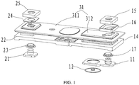
- embodiments of the present application provides a secondary battery, which includes a first terminal 11 and a second terminal 21, the first terminal 11 and the second terminal 21 can be connected with an external circuit so as to form a current loop, and the secondary battery serves as a power supply of the external circuit and outputs electric power for the external circuit.
- the first terminal 11 can be used as a positive electrode terminal, correspondingly, the second terminal 21 is used as a negative electrode terminal, and vice versa.
- the secondary battery provided by the present application is described in detail through embodiments in which the first terminal 11 is used as the positive electrode terminal (the first electrode is the positive electrode), the second terminal 21 is the negative electrode terminal (the second electrode is the negative electrode).
- a secondary battery generally includes an electrode assembly, a housing (not shown in the figures) and a top cover plate 31, the top cover plate can cover on the housing by manners such as welding, so as to form an accommodating cavity, and the electrode assembly is accommodated in the accommodating cavity.
- the electrode assembly generally includes a first electrode and a second electrode, the first electrode has a first electrode tab, the second electrode has a second electrode tab, the first electrode is electrically connected with the first terminal 11 via the first electrode tab, the second electrode is electrically connected with the second terminal 21 via the second electrode tab, so that the electrode assembly can output electric power to the external circuit.
- the secondary battery provided by the present application further includes a contacting plate 12, in the embodiments as shown in FIGs. 1-2 , the contacting plate 12 is attached to the first terminal 11, the top cover plate 31 is insulated from the first terminal 11 and is electrically connected with the second terminal 21.
- the contacting plate and the first terminal 11 can be integrally formed or separately formed.
- the contacting plate 12 When the internal pressure exceeds the reference pressure, the contacting plate 12 deforms and contacts with the top cover plate 31, so as to form an electrical connecting path passing through the first electrode, the first terminal 11, the contacting plate 12, the top cover plate 31, the second terminal 21 and the second electrode, such that the secondary battery will be in an external short circuit state, which therefore reduces the risk of explosion and burning of the secondary battery and improves the safety of the secondary battery.
- the contacting plate 12 when the secondary battery expands or is compressed, the acting force resulted therefrom will be applied onto the top cover plate 31, then the top cover plate 31 will deform and make the contacting plate 12 deform, which generates stress in the interior of the contacting plate 12, and thus the pressure value of the contacting plate 12 during deformation will deviate from the preset reference pressure value, so that the sensitivity of the contacting plate 12 will deteriorate.
- the contacting plate 12 is arranged on the first terminal 11, which avoids the need for an opening on the top cover plate 31 for mounting the contacting plate 12, so as to improve the strength of the top cover plate 31 of a thin wall structure.
- the insulating manner between the top cover plate 31 and the terminal can be implemented, for example, by providing an insulating piece between the terminal and the top cover plate 31.
- a first insulating liner 17 is provided between the first terminal 11 and the top cover plate 31, the first insulating liner 17 is clamped between the first terminal 11 and the top cover plate 31, so as to achieve insulation therebetween.
- the material of the first insulating liner 17 can be rubber, asbestos, etc.
- the top cover plate 31 is electrically connected with the second terminal 21 which is used as the positive electrode terminal, thus, the housing and the top cover plate 31 are both positively charged, so as to reduce the corrosion of the housing and the top cover plate 31 by the electrolyte and extend the service life.
- part of the first terminal 11 and part of the second terminal 21 both extend beyond the top cover plate 31, and the extending portions are connected with the external circuit.
- the terminal can achieve electrical connection with the external circuit via the top cover plate 31.
- the accommodating cavity formed after the top cover plate 31 covers on the housing includes a first chamber S1 and a second chamber S2.
- the first chamber S1 is configured to package the electrode assembly
- the second chamber S2 is configured to provide space where the contacting plate 12 deforms
- the first chamber S1 and the second chamber S2 are separated by the contacting plate 12.
- the top cover plate 31 has a first contacting flat surface 31a, correspondingly, the contacting plate 12 has a second contacting flat surface 121a, and the first contacting flat surface 31a and the second contacting flat surface 121a are fitted with each other when the contacting plate 12 contacts with the top cover plate 31.
- This solution can provide a larger contacting area when the contacting plate 12 contacts with the top cover plate 31, so as to guarantee reliable electrical contact therebetween.
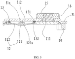
- the contacting plate 12 includes a convex head 121 and a deformable portion 122; the deformable portion 122 is formed in a sheet with a circular surface, thus, the contacting plate 12 can deform and reliably act under the air pressure, the convex head 121 is connected with the deformable portion 122 and protrudes toward the top cover plate 31, so that the contacting plate 12 can contact the top cover plate 31 via the convex head 121 when the contacting plate 12 deforms.
- the surface at a side of the top cover plate 31 toward the contacting plate 12 is a flat surface, which can be regarded as the first contacting flat surface 31a, as for the contacting plate 12, the contacting plate 12 is deformable, since a convex head 121 is provided at the middle portion of the contacting plate 12, thus, even if the contacting plate 12 deforms, the deformation extent of the convex head 121 is relatively small, and the surface at a side of the convex head 121 toward the top cover plate 31 is substantially a flat surface, which therefore can be regarded as the second contacting flat surface 121 a.
- the first terminal 11 includes a terminal body 111 and an extending portion 112 which are connected with each other, the extending portion 112 extends toward the first terminal 11, the extending portion 112 has an opening 112a, part of the outer edge of the contacting plate 12 is sealedly connected with the extending portion 112, so that the contacting plate 12 seals the opening 112a, and separates the first chamber S1 and the second chamber S2.
- the terminal body 111 is configured to electrically connect with the external circuit
- the extending portion 112 is configured to connect with the contacting plate 12, so as to facilitate the configuration of the contacting plate 12 on the first terminal 11.
- the terminal body 111 and the extending portion 112 are of an integrated structure, however, it should be noted that, in some other embodiments, the terminal body 111 and the extending portion 112 can also adopt a separated structure, which is not limited by the present application.
- a positioning table 112b is provided in the opening 112a, the outer edge of the contacting plate 12 has a positioning surface 122a, the positioning surface 122a and the positioning table 112b are positioned and fitted with each other, so as to guarantee that an exact gap is provided between the contacting plate 12 and the top cover plate 31.
- the positioning surface 122a and the positioning table 112b can be fixed by butt seam welding or adhesive bonding after being positioned and fitted with each other, so as to achieve a sealing connection.
- the secondary battery further includes a sealing member 13 which is sealed between the first chamber S1 and the second chamber S2.
- the sealing member 13 is sealedly connected between the extending portion 112 and the top cover plate 31, and the sealing member 13 has a first sealing surface 131 which is sealedly connected with the top cover plate 31 and a second sealing surface 132 which is sealedly connected with the extending portion 112.
- the sealing member 13 is of a ring-shaped structure, a first sealing slot 317 is provided on the top cover plate 31, a second sealing slot 112c is provided on the extending portion 112, more exactly, the second sealing slot 112c is provided on a flat surface which is on the extending portion 112 and perpendicular to the axis of the opening 112a, the second sealing slot 112c surrounds the opening 112a, and the first sealing slot 317 and the second sealing slot 112c are arranged opposite to each other, the sealing member 13 is embedded into the first sealing slot 317 and the second sealing slot 112c, which therefore forms the first sealing surface 131 and the second sealing surface 132 which are arranged opposite to each other along the height direction of the secondary battery, and the first sealing surface 131 sealedly contacts with the bottom surface of the first sealing slot 317, the second sealing surface 132 sealedly contacts with the bottom surface of the second sealing slot 112c.
- the sealing member 13 can be sealedly connected between the contacting plate 12 and the top cover plate 31, and the sealing member 13 has a sealing surface 131 which sealedly contacts with the top cover plate 31 and a second sealing surface 131 which sealedly contacts with the contacting plate 12.
- the sealing structure between the top cover plate 31 and the contacting plate 12 can adopt substantially the same sealing structure as described above, and the second sealing slot is arranged on the contacting plate 12 as long as it will not influence the deformation of the contacting plate 12.
- the cross section of the sealing member 13 is shaped in a crisscross, in some other embodiments, the cross section of the sealing member 13 could also be shaped in a circle.
- the sealing member 13 with a circular cross section or a cross-shaped cross section is convenient for processing and manufacturing, of course, the shape of the cross section the sealing member 13 could also be other irregular shape.
- a plastic piece can be provided between the first terminal 11 and the top cover plate 31, the plastic piece can serve as an insulating piece on one hand, and serve as the sealing member 13 on the other hand, so as to reduce the number of the components needed in the secondary battery and simplify the assembling process.
- the secondary battery provided by the present application further includes an insulating member 18 and a fixing piece 19 which are connected with each other, as shown in FIG. 2 , the fixing piece 19 is fixedly connected with the top cover plate 31, and the extending portion 112 is fixedly connected with the insulating member 18.
- the insulating member 18 and the fixing piece 19 provide reaction force for the extending portion 112, the direction of the reaction force is opposite to the direction of the contacting force when sealing, which alleviates the cantilever structure of the extending portion 112, so as to improve the reliability of the sealing.
- the fixing piece 19 includes an exposed portion 191 which is exposed outside the insulating member 18 and a packaged portion 192 which is packaged inside the insulating member 18, the exposed portion 191 is fixedly connected with the top cover plate 31, the insulating member 18 packages the packaged portion 192, so that the fixing piece 19 is insulated from other components.
- the insulating member 18 and the fixing piece 19 are of an integrated structure, which is formed by integral injection molding.
- the second chamber S2 which provides space where the contacting plate 12 deforms is an airtight chamber
- the pressure of the second chamber S2 is theoretically one bar, however, when the secondary battery generates heat, the pressure in the second chamber S2 will increase, which influences the deformation sensitivity of the contacting plate 12.
- a through hole 313 is provided on the top cover plate 31, the second chamber S2 is communicated with the external environment via the through hole 313, thus, the second chamber S2 is not sealed off and is communicated with the external environment, therefore, the pressure of the air in the second chamber S2 will not increase with the heat generation of the secondary battery, which therefore improves the deformation sensitivity of the contacting plate 12.
- the secondary battery further includes a protection member 41 which is provided on the top cover plate 31 and is exactly opposite to the through hole 313, a channel S3 which is communicated with the through hole 313 is provided between the protection member 41 and the top cover plate 31, the through hole 313 is communicated with the external environment via such channel S3, and the included angel between the extending direction of the channel S3 and the extending direction of the through hole 313 is nonzero.
- the through hole 313 is not externally exposed, but communicated with the external environment via the channel S3, which reduces the risk that the electrolyte and the like entering the through hole 313.
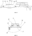
- a groove 314 is provided on the top cover plate 31, the groove 314 is communicated with the through hole 313, the protection member 41 covers the through hole 313 and part of the groove 314, the channel S3 is formed in the groove 314.
- the top cover plate 31 includes a ring-shaped boss 315, the ring-shaped boss 315 protrudes along the axial direction of the through hole 313 and surrounds the through hole 313, the protection member 41 is connected with the ring-shaped end surface of the ring-shaped boss 315, and an vent hole 316 is provided on the ring-shaped wall of the ring-shaped boss 315, the channel S3 includes a space enclosed by the top cover plate 31 and the protection member 41 and a space inside the vent hole 316.
- the secondary battery further includes a resistance member 24, the resistance member 24 is connected in series into an electrical connecting path through the first electrode, the first terminal 11, the contacting plate 12, the top cover plate 31, the second terminal 21 and the second electrode.
- the resistance member 24 due to the resistance member 24, the peak value of the short circuit current of the electrical connecting path can be controlled at the instant of conduction.
- the resistance member 24 plays a role of reducing the peak value of the short circuit current, however, in practical cases, there is also occasion that the contacting position of the contacting plate 12 with the top cover plate 31 fuses, such that the electrode assembly and the external circuit form an open circuit, which avoids dangerous accidents such as burning and explosion, etc.
- the resistance value of the resistance member 24 can be selected from the range of 0.1mohm ⁇ 10mohm, for example, the resistance member 24 can be made of a material selected from a group consisting of steel, stainless steel and nickel-steel alloy, etc.
- the position of the resistance member 24 can be selected according to actual application situation, as shown in FIG. 9 , the resistance member 24 is provided at the second terminal 21, the top cover plate 31 is electrically connected with the second terminal 21 via the resistance member 24. In this solution, the resistance member 24 can be less influenced by the heat generated when the contacting plate 12 contacts with the top cover plate 31.
- the secondary battery may further include a second terminal board 25, the second terminal board 25 is electrically connected with the second terminal 21, in such occasion, the resistance member 24 can be connected in series between the second terminal board 25 and the top cover plate 31, thus, the short circuit current flows through the top cover plate 31, the resistance member 24, the second terminal board 25 and the second terminal 21, which facilitates the arrangement of the resistance member 24.
- the secondary battery may further include a first terminal board 15, the first terminal board 15 is electrically connected with the first terminal 11, and the first terminal board 15 is insulated from the top cover plate 31 through an insulating member 16 which is provided between the first terminal board 15 and the top cover plate 31.
- the first terminal board 15 and the second terminal board 25 can facilitate the connection between the first terminal 11 and the second terminal 21 with the external circuit, which is convenient for assembling, but is not necessarily required.
- the present application further includes a fusing member (not shown in the figures), the fusing member is connected in series into the electrical connecting path through the first electrode, the first terminal 11, the contacting plate 12, the top cover plate 31, the second terminal 21 and the second electrode, moreover, the flow area of the fusing member is less than the flow area at other positions in the electrical connecting path.
- the fusing member can be connected in series between the first electrode and the first terminal 11, or, the fusing member can also be connected in series between the second electrode and the second terminal 21, or, there are two fusing members, one is connected in series between the first electrode and the first terminal 11, the other is connected in series between the second electrode and the second terminal 21. Due to arrangement of the fusing member, the electrical connecting path can fuse at the fusing member when a large short circuit current flows through, so as to cut off the electrode assembly from the external circuit, thereby reducing the risk of burning and explosion of the secondary battery.
- the fusing member can be independently arranged, or integrated with other components as a whole.
- the secondary battery can further includes a first connecting piece and a second connecting piece, the first connecting piece is connected between the first electrode and the first terminal, the second connecting piece is connected between the second electrode and the second terminal.
- the fusing member is formed on at least one of the first connecting piece and the second connecting piece.
- the first connecting piece can serve as an electrical connecting piece which connects the first electrode with the first terminal 11
- the second connecting piece can serve as an electrical connecting piece which connects the second electrode with the second terminal 21, which improves the assembling process of the secondary battery and avoids deformation of the first electrode tab and the second electrode tab during assembling.
- the fusing member formed on the first connecting piece or the second connecting piece can fuse, which then cuts off the short circuit passing through the first electrode and the second electrode.
- the fusing member can be implemented by providing a gap or a hole on the first connecting piece, such that the flow area formed on the first connecting piece is less than the flow area on the other positions, the position with smaller flow area is the location of the fusing member.
- the forming manner of the fusing member on the second connecting piece can adopt the above structure, which will not be repeated herein.
- both the fusing member and the resistance member 24 can be connected in series into the electrical connecting path through the first electrode, the first terminal 11, the contacting plate 12, the top cover plate 31, the second terminal 21 and the second electrode, the resistance member 24 can reduce the short circuit current at the instant the contacting plate 12 contacts with the top cover plate 31, however, the reduced short circuit current is sufficient to fuse the fusing member, so as to cut off the electrical connecting path.
- the secondary battery further includes a first insulating piece 14 and a second insulating piece 22, the first insulating piece 14 and the second insulating piece 22 are provided underneath the top cover plate 31 for increasing the electric clearance and the creepage distance between the electrode assembly and the top cover plate 31, so as to avoid the conduction between the electrode assembly and the top cover plate 31.
- first terminal 11 is the positive electrode terminal and the second terminal 21 is the negative electrode terminal
- present application is not limited to the above embodiments, for example, the first terminal 11 can also be used as a negative electrode terminal and the second terminal 21 can be used as a positive electrode terminal.
Landscapes
- Chemical & Material Sciences (AREA)
- Chemical Kinetics & Catalysis (AREA)
- Electrochemistry (AREA)
- General Chemical & Material Sciences (AREA)
- Engineering & Computer Science (AREA)
- Manufacturing & Machinery (AREA)
- Connection Of Batteries Or Terminals (AREA)
- Sealing Battery Cases Or Jackets (AREA)
- Secondary Cells (AREA)
Applications Claiming Priority (1)
| Application Number | Priority Date | Filing Date | Title |
|---|---|---|---|
| CN201611028083.0A CN106450063B (zh) | 2016-11-15 | 2016-11-15 | 二次电池 |
Publications (2)
| Publication Number | Publication Date |
|---|---|
| EP3321998A1 true EP3321998A1 (de) | 2018-05-16 |
| EP3321998B1 EP3321998B1 (de) | 2020-08-19 |
Family
ID=58220931
Family Applications (1)
| Application Number | Title | Priority Date | Filing Date |
|---|---|---|---|
| EP17000793.4A Active EP3321998B1 (de) | 2016-11-15 | 2017-05-09 | Sekundärbatterie |
Country Status (4)
| Country | Link |
|---|---|
| US (1) | US10553837B2 (de) |
| EP (1) | EP3321998B1 (de) |
| JP (1) | JP6529566B2 (de) |
| CN (1) | CN106450063B (de) |
Cited By (2)
| Publication number | Priority date | Publication date | Assignee | Title |
|---|---|---|---|---|
| EP3826082A4 (de) * | 2019-10-10 | 2021-06-23 | Ningde Amperex Technology Ltd. | Batteriegehäuseanordnung und batterie damit |
| CN115176377A (zh) * | 2020-03-09 | 2022-10-11 | 三洋电机株式会社 | 密闭电池 |
Families Citing this family (14)
| Publication number | Priority date | Publication date | Assignee | Title |
|---|---|---|---|---|
| CN107123774B (zh) * | 2016-02-25 | 2019-10-11 | 比亚迪股份有限公司 | 单体电池、电池模组、动力电池及电动汽车 |
| CN111799404B (zh) * | 2017-08-30 | 2021-05-07 | 宁德时代新能源科技股份有限公司 | 二次电池的顶盖组件、二次电池以及电池模组 |
| CN111799402B (zh) * | 2017-08-30 | 2021-06-25 | 宁德时代新能源科技股份有限公司 | 二次电池以及电池模组 |
| CN109671878B (zh) * | 2017-10-17 | 2021-09-21 | 宁德时代新能源科技股份有限公司 | 电池顶盖组件及二次电池 |
| CN108110158A (zh) * | 2017-11-17 | 2018-06-01 | 深圳市瑞德丰精密制造有限公司 | 电池的顶盖结构 |
| CN107946526A (zh) * | 2017-11-17 | 2018-04-20 | 深圳市瑞德丰精密制造有限公司 | 带有翻转片的导电块结构 |
| CN117855703A (zh) * | 2018-06-14 | 2024-04-09 | 宁德时代新能源科技股份有限公司 | 顶盖组件及二次电池 |
| CN110797478B (zh) * | 2018-08-01 | 2021-08-24 | 宁德时代新能源科技股份有限公司 | 二次电池 |
| CN111384348B (zh) * | 2018-12-29 | 2024-09-13 | 宁德时代新能源科技股份有限公司 | 二次电池和电池模组 |
| CN110176557B (zh) * | 2019-04-09 | 2024-04-05 | 宁德时代新能源科技股份有限公司 | 二次电池及其顶盖组件 |
| CN112271362B (zh) * | 2020-11-10 | 2023-06-09 | 深圳市红阳光能源技术有限公司 | 一种便于拆卸的锂电池盖板 |
| US20220311080A1 (en) * | 2021-03-24 | 2022-09-29 | Ford Global Technologies, Llc | Anti-filiform corrosion channels |
| WO2023220873A1 (zh) * | 2022-05-16 | 2023-11-23 | 宁德时代新能源科技股份有限公司 | 电池单体的端盖组件、电池单体、电池以及用电设备 |
| CN115117527B (zh) * | 2022-06-06 | 2024-03-08 | 宜兴市泰宇汽车零部件有限公司 | 一种具有通风阻燃防潮效果的复合型epp电池盖板 |
Citations (5)
| Publication number | Priority date | Publication date | Assignee | Title |
|---|---|---|---|---|
| US20120315516A1 (en) * | 2011-06-08 | 2012-12-13 | Duk-Jung Kim | Rechargeable battery |
| US20130115511A1 (en) * | 2011-11-07 | 2013-05-09 | Minyeol Han | Secondary battery |
| EP2816637A1 (de) * | 2013-06-19 | 2014-12-24 | Samsung SDI Co., Ltd. | Wiederaufladbare Batterie |
| US20150249241A1 (en) * | 2014-02-28 | 2015-09-03 | Samsung Sdi Co., Ltd. | Rechargeable battery having top insulation member |
| CN204668368U (zh) * | 2015-06-11 | 2015-09-23 | 宁德时代新能源科技有限公司 | 动力电池顶盖结构及动力电池 |
Family Cites Families (12)
| Publication number | Priority date | Publication date | Assignee | Title |
|---|---|---|---|---|
| US8440336B2 (en) | 2009-12-08 | 2013-05-14 | Samsung Sdi Co., Ltd. | Rechargeable battery with short circuit member |
| KR101116449B1 (ko) * | 2010-01-26 | 2012-02-27 | 에스비리모티브 주식회사 | 이차 전지 |
| CN102136552B (zh) * | 2010-01-27 | 2015-11-25 | 深圳市比克电池有限公司 | 电池保护装置、电池及电池保护装置的制作方法 |
| JP2012011930A (ja) | 2010-07-02 | 2012-01-19 | Panasonic Corp | 車両用液体循環システム |
| US9478774B2 (en) * | 2010-12-02 | 2016-10-25 | Samsung Sdi Co., Ltd. | Rechargeable battery |
| KR101243475B1 (ko) | 2011-03-30 | 2013-03-13 | 로베르트 보쉬 게엠베하 | 단락 부재를 구비한 이차 전지 |
| KR101254886B1 (ko) | 2011-04-04 | 2013-04-15 | 로베르트 보쉬 게엠베하 | 이차 전지 |
| JP5911772B2 (ja) | 2012-08-09 | 2016-04-27 | 三洋電機株式会社 | 非水電解質二次電池及びその製造方法 |
| KR101675618B1 (ko) * | 2013-02-20 | 2016-11-11 | 삼성에스디아이 주식회사 | 이차 전지 |
| KR20150086998A (ko) * | 2014-01-21 | 2015-07-29 | 삼성에스디아이 주식회사 | 이차 전지 |
| KR102108277B1 (ko) | 2014-03-17 | 2020-05-07 | 삼성에스디아이 주식회사 | 이차 전지 |
| KR102332447B1 (ko) * | 2015-02-26 | 2021-11-26 | 삼성에스디아이 주식회사 | 이차 전지 |
-
2016
- 2016-11-15 CN CN201611028083.0A patent/CN106450063B/zh active Active
-
2017
- 2017-05-09 EP EP17000793.4A patent/EP3321998B1/de active Active
- 2017-05-18 US US15/599,038 patent/US10553837B2/en active Active
- 2017-11-14 JP JP2017218975A patent/JP6529566B2/ja active Active
Patent Citations (6)
| Publication number | Priority date | Publication date | Assignee | Title |
|---|---|---|---|---|
| US20120315516A1 (en) * | 2011-06-08 | 2012-12-13 | Duk-Jung Kim | Rechargeable battery |
| US20130115511A1 (en) * | 2011-11-07 | 2013-05-09 | Minyeol Han | Secondary battery |
| EP2816637A1 (de) * | 2013-06-19 | 2014-12-24 | Samsung SDI Co., Ltd. | Wiederaufladbare Batterie |
| US20150249241A1 (en) * | 2014-02-28 | 2015-09-03 | Samsung Sdi Co., Ltd. | Rechargeable battery having top insulation member |
| CN204668368U (zh) * | 2015-06-11 | 2015-09-23 | 宁德时代新能源科技有限公司 | 动力电池顶盖结构及动力电池 |
| EP3104431A1 (de) * | 2015-06-11 | 2016-12-14 | Contemporary Amperex Technology Co., Limited | Abdeckungsstruktur einer strombatterie und strombatterie |
Cited By (4)
| Publication number | Priority date | Publication date | Assignee | Title |
|---|---|---|---|---|
| EP3826082A4 (de) * | 2019-10-10 | 2021-06-23 | Ningde Amperex Technology Ltd. | Batteriegehäuseanordnung und batterie damit |
| US11996570B2 (en) | 2019-10-10 | 2024-05-28 | Ningde Amperex Technology Ltd | Battery casing assembly and battery having the same |
| CN115176377A (zh) * | 2020-03-09 | 2022-10-11 | 三洋电机株式会社 | 密闭电池 |
| CN115176377B (zh) * | 2020-03-09 | 2024-06-11 | 松下新能源株式会社 | 密闭电池 |
Also Published As
| Publication number | Publication date |
|---|---|
| CN106450063A (zh) | 2017-02-22 |
| EP3321998B1 (de) | 2020-08-19 |
| CN106450063B (zh) | 2019-07-19 |
| US10553837B2 (en) | 2020-02-04 |
| US20180138465A1 (en) | 2018-05-17 |
| JP6529566B2 (ja) | 2019-06-12 |
| JP2018081913A (ja) | 2018-05-24 |
Similar Documents
| Publication | Publication Date | Title |
|---|---|---|
| EP3321998B1 (de) | Sekundärbatterie | |
| EP3322001B1 (de) | Sekundärbatterie und batteriemodul | |
| US10673056B2 (en) | Secondary battery | |
| US10050251B2 (en) | Secondary battery pack of compact structure | |
| KR100578804B1 (ko) | 캡 조립체 및 이를 구비한 이차 전지 | |
| US8877361B2 (en) | Rechargeable battery | |
| US7763379B2 (en) | Cap assembly mold and secondary battery having the same | |
| US8592066B2 (en) | Battery assembly | |
| JP5507623B2 (ja) | 非水電解質二次電池 | |
| KR20090110711A (ko) | 배터리 팩 | |
| CN111788715B (zh) | 二次电池 | |
| KR20020071179A (ko) | 이차 전지와 그 제조방법 | |
| US20190074486A1 (en) | Top Cover Assembly Of Secondary Battery And Secondary Battery | |
| CN107170947B (zh) | 二次电池以及二次电池集合体 | |
| CN218827490U (zh) | 电池的端盖组件、电池单体、储能装置及用电设备 | |
| EP3333929B1 (de) | Sekundärbatterie | |
| KR100936259B1 (ko) | 우수한 제조공정성 및 구조적 안정성의 이차전지 팩 | |
| KR19980702192A (ko) | 박형전지 | |
| KR20000026860A (ko) | 2차 전지 조립체 | |
| KR100788558B1 (ko) | 팩 전지 | |
| JP2000260421A (ja) | 電池の感圧電路遮断機構 | |
| KR101543239B1 (ko) | 형상기억합금이 적용된 전지용 퓨즈 | |
| JP7551847B2 (ja) | 二次電池および二次電池集合体 | |
| JPH11329402A (ja) | 電池の電路遮断部品 | |
| CN109792009B (zh) | 二次电池 |
Legal Events
| Date | Code | Title | Description |
|---|---|---|---|
| PUAI | Public reference made under article 153(3) epc to a published international application that has entered the european phase |
Free format text: ORIGINAL CODE: 0009012 |
|
| STAA | Information on the status of an ep patent application or granted ep patent |
Free format text: STATUS: REQUEST FOR EXAMINATION WAS MADE |
|
| 17P | Request for examination filed |
Effective date: 20170608 |
|
| AK | Designated contracting states |
Kind code of ref document: A1 Designated state(s): AL AT BE BG CH CY CZ DE DK EE ES FI FR GB GR HR HU IE IS IT LI LT LU LV MC MK MT NL NO PL PT RO RS SE SI SK SM TR |
|
| AX | Request for extension of the european patent |
Extension state: BA ME |
|
| STAA | Information on the status of an ep patent application or granted ep patent |
Free format text: STATUS: EXAMINATION IS IN PROGRESS |
|
| 17Q | First examination report despatched |
Effective date: 20181029 |
|
| RBV | Designated contracting states (corrected) |
Designated state(s): AL AT BE BG CH CY CZ DE DK EE ES FI FR GB GR HR HU IE IS IT LI LT LU LV MC MK MT NL NO PL PT RO RS SE SI SK SM TR |
|
| GRAP | Despatch of communication of intention to grant a patent |
Free format text: ORIGINAL CODE: EPIDOSNIGR1 |
|
| STAA | Information on the status of an ep patent application or granted ep patent |
Free format text: STATUS: GRANT OF PATENT IS INTENDED |
|
| INTG | Intention to grant announced |
Effective date: 20200403 |
|
| INTG | Intention to grant announced |
Effective date: 20200408 |
|
| INTG | Intention to grant announced |
Effective date: 20200420 |
|
| GRAS | Grant fee paid |
Free format text: ORIGINAL CODE: EPIDOSNIGR3 |
|
| GRAA | (expected) grant |
Free format text: ORIGINAL CODE: 0009210 |
|
| STAA | Information on the status of an ep patent application or granted ep patent |
Free format text: STATUS: THE PATENT HAS BEEN GRANTED |
|
| AK | Designated contracting states |
Kind code of ref document: B1 Designated state(s): AL AT BE BG CH CY CZ DE DK EE ES FI FR GB GR HR HU IE IS IT LI LT LU LV MC MK MT NL NO PL PT RO RS SE SI SK SM TR |
|
| REG | Reference to a national code |
Ref country code: CH Ref legal event code: EP |
|
| REG | Reference to a national code |
Ref country code: DE Ref legal event code: R096 Ref document number: 602017021743 Country of ref document: DE |
|
| REG | Reference to a national code |
Ref country code: AT Ref legal event code: REF Ref document number: 1304963 Country of ref document: AT Kind code of ref document: T Effective date: 20200915 |
|
| REG | Reference to a national code |
Ref country code: IE Ref legal event code: FG4D |
|
| REG | Reference to a national code |
Ref country code: DE Ref legal event code: R079 Ref document number: 602017021743 Country of ref document: DE Free format text: PREVIOUS MAIN CLASS: H01M0002120000 Ipc: H01M0050300000 |
|
| REG | Reference to a national code |
Ref country code: LT Ref legal event code: MG4D |
|
| REG | Reference to a national code |
Ref country code: NL Ref legal event code: MP Effective date: 20200819 |
|
| PG25 | Lapsed in a contracting state [announced via postgrant information from national office to epo] |
Ref country code: SE Free format text: LAPSE BECAUSE OF FAILURE TO SUBMIT A TRANSLATION OF THE DESCRIPTION OR TO PAY THE FEE WITHIN THE PRESCRIBED TIME-LIMIT Effective date: 20200819 Ref country code: BG Free format text: LAPSE BECAUSE OF FAILURE TO SUBMIT A TRANSLATION OF THE DESCRIPTION OR TO PAY THE FEE WITHIN THE PRESCRIBED TIME-LIMIT Effective date: 20201119 Ref country code: PT Free format text: LAPSE BECAUSE OF FAILURE TO SUBMIT A TRANSLATION OF THE DESCRIPTION OR TO PAY THE FEE WITHIN THE PRESCRIBED TIME-LIMIT Effective date: 20201221 Ref country code: NO Free format text: LAPSE BECAUSE OF FAILURE TO SUBMIT A TRANSLATION OF THE DESCRIPTION OR TO PAY THE FEE WITHIN THE PRESCRIBED TIME-LIMIT Effective date: 20201119 Ref country code: FI Free format text: LAPSE BECAUSE OF FAILURE TO SUBMIT A TRANSLATION OF THE DESCRIPTION OR TO PAY THE FEE WITHIN THE PRESCRIBED TIME-LIMIT Effective date: 20200819 Ref country code: LT Free format text: LAPSE BECAUSE OF FAILURE TO SUBMIT A TRANSLATION OF THE DESCRIPTION OR TO PAY THE FEE WITHIN THE PRESCRIBED TIME-LIMIT Effective date: 20200819 Ref country code: GR Free format text: LAPSE BECAUSE OF FAILURE TO SUBMIT A TRANSLATION OF THE DESCRIPTION OR TO PAY THE FEE WITHIN THE PRESCRIBED TIME-LIMIT Effective date: 20201120 Ref country code: HR Free format text: LAPSE BECAUSE OF FAILURE TO SUBMIT A TRANSLATION OF THE DESCRIPTION OR TO PAY THE FEE WITHIN THE PRESCRIBED TIME-LIMIT Effective date: 20200819 |
|
| REG | Reference to a national code |
Ref country code: AT Ref legal event code: MK05 Ref document number: 1304963 Country of ref document: AT Kind code of ref document: T Effective date: 20200819 |
|
| PG25 | Lapsed in a contracting state [announced via postgrant information from national office to epo] |
Ref country code: NL Free format text: LAPSE BECAUSE OF FAILURE TO SUBMIT A TRANSLATION OF THE DESCRIPTION OR TO PAY THE FEE WITHIN THE PRESCRIBED TIME-LIMIT Effective date: 20200819 Ref country code: RS Free format text: LAPSE BECAUSE OF FAILURE TO SUBMIT A TRANSLATION OF THE DESCRIPTION OR TO PAY THE FEE WITHIN THE PRESCRIBED TIME-LIMIT Effective date: 20200819 Ref country code: PL Free format text: LAPSE BECAUSE OF FAILURE TO SUBMIT A TRANSLATION OF THE DESCRIPTION OR TO PAY THE FEE WITHIN THE PRESCRIBED TIME-LIMIT Effective date: 20200819 Ref country code: LV Free format text: LAPSE BECAUSE OF FAILURE TO SUBMIT A TRANSLATION OF THE DESCRIPTION OR TO PAY THE FEE WITHIN THE PRESCRIBED TIME-LIMIT Effective date: 20200819 Ref country code: IS Free format text: LAPSE BECAUSE OF FAILURE TO SUBMIT A TRANSLATION OF THE DESCRIPTION OR TO PAY THE FEE WITHIN THE PRESCRIBED TIME-LIMIT Effective date: 20201219 |
|
| PG25 | Lapsed in a contracting state [announced via postgrant information from national office to epo] |
Ref country code: RO Free format text: LAPSE BECAUSE OF FAILURE TO SUBMIT A TRANSLATION OF THE DESCRIPTION OR TO PAY THE FEE WITHIN THE PRESCRIBED TIME-LIMIT Effective date: 20200819 Ref country code: DK Free format text: LAPSE BECAUSE OF FAILURE TO SUBMIT A TRANSLATION OF THE DESCRIPTION OR TO PAY THE FEE WITHIN THE PRESCRIBED TIME-LIMIT Effective date: 20200819 Ref country code: CZ Free format text: LAPSE BECAUSE OF FAILURE TO SUBMIT A TRANSLATION OF THE DESCRIPTION OR TO PAY THE FEE WITHIN THE PRESCRIBED TIME-LIMIT Effective date: 20200819 Ref country code: EE Free format text: LAPSE BECAUSE OF FAILURE TO SUBMIT A TRANSLATION OF THE DESCRIPTION OR TO PAY THE FEE WITHIN THE PRESCRIBED TIME-LIMIT Effective date: 20200819 Ref country code: SM Free format text: LAPSE BECAUSE OF FAILURE TO SUBMIT A TRANSLATION OF THE DESCRIPTION OR TO PAY THE FEE WITHIN THE PRESCRIBED TIME-LIMIT Effective date: 20200819 |
|
| REG | Reference to a national code |
Ref country code: DE Ref legal event code: R097 Ref document number: 602017021743 Country of ref document: DE |
|
| PG25 | Lapsed in a contracting state [announced via postgrant information from national office to epo] |
Ref country code: ES Free format text: LAPSE BECAUSE OF FAILURE TO SUBMIT A TRANSLATION OF THE DESCRIPTION OR TO PAY THE FEE WITHIN THE PRESCRIBED TIME-LIMIT Effective date: 20200819 Ref country code: AL Free format text: LAPSE BECAUSE OF FAILURE TO SUBMIT A TRANSLATION OF THE DESCRIPTION OR TO PAY THE FEE WITHIN THE PRESCRIBED TIME-LIMIT Effective date: 20200819 Ref country code: AT Free format text: LAPSE BECAUSE OF FAILURE TO SUBMIT A TRANSLATION OF THE DESCRIPTION OR TO PAY THE FEE WITHIN THE PRESCRIBED TIME-LIMIT Effective date: 20200819 |
|
| PLBE | No opposition filed within time limit |
Free format text: ORIGINAL CODE: 0009261 |
|
| STAA | Information on the status of an ep patent application or granted ep patent |
Free format text: STATUS: NO OPPOSITION FILED WITHIN TIME LIMIT |
|
| PG25 | Lapsed in a contracting state [announced via postgrant information from national office to epo] |
Ref country code: SK Free format text: LAPSE BECAUSE OF FAILURE TO SUBMIT A TRANSLATION OF THE DESCRIPTION OR TO PAY THE FEE WITHIN THE PRESCRIBED TIME-LIMIT Effective date: 20200819 |
|
| 26N | No opposition filed |
Effective date: 20210520 |
|
| PG25 | Lapsed in a contracting state [announced via postgrant information from national office to epo] |
Ref country code: IT Free format text: LAPSE BECAUSE OF FAILURE TO SUBMIT A TRANSLATION OF THE DESCRIPTION OR TO PAY THE FEE WITHIN THE PRESCRIBED TIME-LIMIT Effective date: 20200819 |
|
| PG25 | Lapsed in a contracting state [announced via postgrant information from national office to epo] |
Ref country code: SI Free format text: LAPSE BECAUSE OF FAILURE TO SUBMIT A TRANSLATION OF THE DESCRIPTION OR TO PAY THE FEE WITHIN THE PRESCRIBED TIME-LIMIT Effective date: 20200819 |
|
| REG | Reference to a national code |
Ref country code: CH Ref legal event code: PL |
|
| PG25 | Lapsed in a contracting state [announced via postgrant information from national office to epo] |
Ref country code: CH Free format text: LAPSE BECAUSE OF NON-PAYMENT OF DUE FEES Effective date: 20210531 Ref country code: LI Free format text: LAPSE BECAUSE OF NON-PAYMENT OF DUE FEES Effective date: 20210531 Ref country code: MC Free format text: LAPSE BECAUSE OF FAILURE TO SUBMIT A TRANSLATION OF THE DESCRIPTION OR TO PAY THE FEE WITHIN THE PRESCRIBED TIME-LIMIT Effective date: 20200819 Ref country code: LU Free format text: LAPSE BECAUSE OF NON-PAYMENT OF DUE FEES Effective date: 20210509 |
|
| REG | Reference to a national code |
Ref country code: BE Ref legal event code: MM Effective date: 20210531 |
|
| PG25 | Lapsed in a contracting state [announced via postgrant information from national office to epo] |
Ref country code: IE Free format text: LAPSE BECAUSE OF NON-PAYMENT OF DUE FEES Effective date: 20210509 |
|
| REG | Reference to a national code |
Ref document number: 602017021743 Country of ref document: DE Ref country code: DE Ref legal event code: R082 Representative=s name: FARAGO PATENTANWAELTE GMBH, DE Ref country code: DE Ref legal event code: R082 Ref document number: 602017021743 Country of ref document: DE Representative=s name: FARAGO PATENTANWALTSGESELLSCHAFT MBH, DE |
|
| PG25 | Lapsed in a contracting state [announced via postgrant information from national office to epo] |
Ref country code: BE Free format text: LAPSE BECAUSE OF NON-PAYMENT OF DUE FEES Effective date: 20210531 |
|
| P01 | Opt-out of the competence of the unified patent court (upc) registered |
Effective date: 20230516 |
|
| PG25 | Lapsed in a contracting state [announced via postgrant information from national office to epo] |
Ref country code: CY Free format text: LAPSE BECAUSE OF FAILURE TO SUBMIT A TRANSLATION OF THE DESCRIPTION OR TO PAY THE FEE WITHIN THE PRESCRIBED TIME-LIMIT Effective date: 20200819 |
|
| PG25 | Lapsed in a contracting state [announced via postgrant information from national office to epo] |
Ref country code: HU Free format text: LAPSE BECAUSE OF FAILURE TO SUBMIT A TRANSLATION OF THE DESCRIPTION OR TO PAY THE FEE WITHIN THE PRESCRIBED TIME-LIMIT; INVALID AB INITIO Effective date: 20170509 |
|
| PG25 | Lapsed in a contracting state [announced via postgrant information from national office to epo] |
Ref country code: MK Free format text: LAPSE BECAUSE OF FAILURE TO SUBMIT A TRANSLATION OF THE DESCRIPTION OR TO PAY THE FEE WITHIN THE PRESCRIBED TIME-LIMIT Effective date: 20200819 |
|
| PGFP | Annual fee paid to national office [announced via postgrant information from national office to epo] |
Ref country code: GB Payment date: 20240321 Year of fee payment: 8 |
|
| PGFP | Annual fee paid to national office [announced via postgrant information from national office to epo] |
Ref country code: FR Payment date: 20240308 Year of fee payment: 8 |
|
| PGFP | Annual fee paid to national office [announced via postgrant information from national office to epo] |
Ref country code: DE Payment date: 20240313 Year of fee payment: 8 |
|
| REG | Reference to a national code |
Ref country code: DE Ref legal event code: R082 Ref document number: 602017021743 Country of ref document: DE Ref country code: DE Ref legal event code: R081 Ref document number: 602017021743 Country of ref document: DE Owner name: CONTEMPORARY AMPEREX TECHNOLOGY (HONG KONG) LT, HK Free format text: FORMER OWNER: CONTEMPORARY AMPEREX TECHNOLOGY CO., LIMITED, CITY FUJIAN, JIAOCHENG DISTRICT NINGDE, CN |
|
| REG | Reference to a national code |
Ref country code: GB Ref legal event code: 732E Free format text: REGISTERED BETWEEN 20240801 AND 20240807 |