EP3321990B1 - Flussbatterie, herstellunsverfahren und verwendung - Google Patents
Flussbatterie, herstellunsverfahren und verwendung Download PDFInfo
- Publication number
- EP3321990B1 EP3321990B1 EP16198551.0A EP16198551A EP3321990B1 EP 3321990 B1 EP3321990 B1 EP 3321990B1 EP 16198551 A EP16198551 A EP 16198551A EP 3321990 B1 EP3321990 B1 EP 3321990B1
- Authority
- EP
- European Patent Office
- Prior art keywords
- chamber
- battery
- wall
- air electrode
- ducts
- Prior art date
- Legal status (The legal status is an assumption and is not a legal conclusion. Google has not performed a legal analysis and makes no representation as to the accuracy of the status listed.)
- Active
Links
Images

Classifications
-
- H—ELECTRICITY
- H01—ELECTRIC ELEMENTS
- H01M—PROCESSES OR MEANS, e.g. BATTERIES, FOR THE DIRECT CONVERSION OF CHEMICAL ENERGY INTO ELECTRICAL ENERGY
- H01M12/00—Hybrid cells; Manufacture thereof
- H01M12/04—Hybrid cells; Manufacture thereof composed of a half-cell of the fuel-cell type and of a half-cell of the primary-cell type
- H01M12/06—Hybrid cells; Manufacture thereof composed of a half-cell of the fuel-cell type and of a half-cell of the primary-cell type with one metallic and one gaseous electrode
- H01M12/065—Hybrid cells; Manufacture thereof composed of a half-cell of the fuel-cell type and of a half-cell of the primary-cell type with one metallic and one gaseous electrode with plate-like electrodes or stacks of plate-like electrodes
-
- H—ELECTRICITY
- H01—ELECTRIC ELEMENTS
- H01M—PROCESSES OR MEANS, e.g. BATTERIES, FOR THE DIRECT CONVERSION OF CHEMICAL ENERGY INTO ELECTRICAL ENERGY
- H01M12/00—Hybrid cells; Manufacture thereof
- H01M12/08—Hybrid cells; Manufacture thereof composed of a half-cell of a fuel-cell type and a half-cell of the secondary-cell type
-
- H—ELECTRICITY
- H01—ELECTRIC ELEMENTS
- H01M—PROCESSES OR MEANS, e.g. BATTERIES, FOR THE DIRECT CONVERSION OF CHEMICAL ENERGY INTO ELECTRICAL ENERGY
- H01M50/00—Constructional details or processes of manufacture of the non-active parts of electrochemical cells other than fuel cells, e.g. hybrid cells
- H01M50/10—Primary casings; Jackets or wrappings
- H01M50/138—Primary casings; Jackets or wrappings adapted for specific cells, e.g. electrochemical cells operating at high temperature
- H01M50/1385—Hybrid cells
-
- H—ELECTRICITY
- H01—ELECTRIC ELEMENTS
- H01M—PROCESSES OR MEANS, e.g. BATTERIES, FOR THE DIRECT CONVERSION OF CHEMICAL ENERGY INTO ELECTRICAL ENERGY
- H01M2220/00—Batteries for particular applications
- H01M2220/20—Batteries in motive systems, e.g. vehicle, ship, plane
-
- H—ELECTRICITY
- H01—ELECTRIC ELEMENTS
- H01M—PROCESSES OR MEANS, e.g. BATTERIES, FOR THE DIRECT CONVERSION OF CHEMICAL ENERGY INTO ELECTRICAL ENERGY
- H01M2300/00—Electrolytes
- H01M2300/0017—Non-aqueous electrolytes
- H01M2300/0025—Organic electrolyte
- H01M2300/0045—Room temperature molten salts comprising at least one organic ion
-
- H—ELECTRICITY
- H01—ELECTRIC ELEMENTS
- H01M—PROCESSES OR MEANS, e.g. BATTERIES, FOR THE DIRECT CONVERSION OF CHEMICAL ENERGY INTO ELECTRICAL ENERGY
- H01M4/00—Electrodes
- H01M4/86—Inert electrodes with catalytic activity, e.g. for fuel cells
- H01M4/8605—Porous electrodes
- H01M4/8626—Porous electrodes characterised by the form
-
- H—ELECTRICITY
- H01—ELECTRIC ELEMENTS
- H01M—PROCESSES OR MEANS, e.g. BATTERIES, FOR THE DIRECT CONVERSION OF CHEMICAL ENERGY INTO ELECTRICAL ENERGY
- H01M4/00—Electrodes
- H01M4/86—Inert electrodes with catalytic activity, e.g. for fuel cells
- H01M4/88—Processes of manufacture
- H01M4/8803—Supports for the deposition of the catalytic active composition
- H01M4/8807—Gas diffusion layers
-
- H—ELECTRICITY
- H01—ELECTRIC ELEMENTS
- H01M—PROCESSES OR MEANS, e.g. BATTERIES, FOR THE DIRECT CONVERSION OF CHEMICAL ENERGY INTO ELECTRICAL ENERGY
- H01M4/00—Electrodes
- H01M4/86—Inert electrodes with catalytic activity, e.g. for fuel cells
- H01M4/88—Processes of manufacture
- H01M4/8825—Methods for deposition of the catalytic active composition
- H01M4/8828—Coating with slurry or ink
-
- H—ELECTRICITY
- H01—ELECTRIC ELEMENTS
- H01M—PROCESSES OR MEANS, e.g. BATTERIES, FOR THE DIRECT CONVERSION OF CHEMICAL ENERGY INTO ELECTRICAL ENERGY
- H01M4/00—Electrodes
- H01M4/86—Inert electrodes with catalytic activity, e.g. for fuel cells
- H01M4/88—Processes of manufacture
- H01M4/8875—Methods for shaping the electrode into free-standing bodies, like sheets, films or grids, e.g. moulding, hot-pressing, casting without support, extrusion without support
-
- H—ELECTRICITY
- H01—ELECTRIC ELEMENTS
- H01M—PROCESSES OR MEANS, e.g. BATTERIES, FOR THE DIRECT CONVERSION OF CHEMICAL ENERGY INTO ELECTRICAL ENERGY
- H01M4/00—Electrodes
- H01M4/86—Inert electrodes with catalytic activity, e.g. for fuel cells
- H01M4/88—Processes of manufacture
- H01M4/8878—Treatment steps after deposition of the catalytic active composition or after shaping of the electrode being free-standing body
- H01M4/8882—Heat treatment, e.g. drying, baking
- H01M4/8885—Sintering or firing
- H01M4/8889—Cosintering or cofiring of a catalytic active layer with another type of layer
-
- Y—GENERAL TAGGING OF NEW TECHNOLOGICAL DEVELOPMENTS; GENERAL TAGGING OF CROSS-SECTIONAL TECHNOLOGIES SPANNING OVER SEVERAL SECTIONS OF THE IPC; TECHNICAL SUBJECTS COVERED BY FORMER USPC CROSS-REFERENCE ART COLLECTIONS [XRACs] AND DIGESTS
- Y02—TECHNOLOGIES OR APPLICATIONS FOR MITIGATION OR ADAPTATION AGAINST CLIMATE CHANGE
- Y02E—REDUCTION OF GREENHOUSE GAS [GHG] EMISSIONS, RELATED TO ENERGY GENERATION, TRANSMISSION OR DISTRIBUTION
- Y02E60/00—Enabling technologies; Technologies with a potential or indirect contribution to GHG emissions mitigation
- Y02E60/10—Energy storage using batteries
Definitions
- the invention pertains to a flow battery, particularly a metal-air flow battery.
- the pressurized fluid biases the anode toward the cathode during anode consumption, and the diaphragm provides for longitudinal and angular movement of the anode to accommodate uneven corrosion of the anode.
- the frames of adjacent cells define a third chamber therebetween for the introduction of consumable gas to the cathode.
- An array of manifolds is formed throughout the frames of adjacent power cells for introducing electrolyte between the anode and the cathode, for introducing consumable gas to the cathode and for introducing fluid under pressure to the expansion chamber.
- a reduction of sealing surfaces may be achieved to avoid leakage.
- leakage poses a major problem with known flow batteries, where components such as air electrode, separator, bipolar plate, and circuitry need to be stacked and mutually sealed.
- components such as air electrode, separator, bipolar plate, and circuitry need to be stacked and mutually sealed.
- the use of different materials of varying porosity and surface texture typically impedes the implementation of a seal that is free from leakage.
- the separator film used in these devices tends to roll away, further complicating the stacking procedure.
- Another embodiment provides for the introduction of energizing elements into the channel structure to enhance fluid flow by avoiding dead water areas, calculus generation, or clogging, increase turbulence and ionic conductivity, and improve clustering as well as hydrogen bonding. These improvements in turn lead to an increased self-cleaning capacity of the air electrode, ultimately resulting in an extended service life of the resulting battery.
- Said energizing elements may possess various characteristics and consist of materials such as synthetics, ferromagnetic and other metals, crystals, and further constituents selected to affect clustering in water.
- such elements are of a streamlined, flat shape that offers light flow resistance while introducing turbulence into the fluid flow, thus promoting mixing. This way, metal particles carried axially in the fluid without prior conductor contact may be pressed against the channel wall where they can undergo the desired reaction.
- the structural, conceptional, material, and procedural aspects of the invention render the proposed battery suited as a torsionally rigid tube for light-weight design.
- its multi-chambered ducts may serve a dual purpose both as a structural and functional element.
- the inventive approach facilitates a massive increase in energy density compared to conventional flow batteries: In the latter case, the reactor, failing to contribute to the supporting structure, essentially constitutes dead mass when incorporated into a vehicle or other mobile apparatus.
- an embodiment of the invention permits a highly scalable BEV design. When filled with ionic fluid, the battery may even achieve a cooling effect.
- the uniform structure inherent to an embodiment of the invention allows for a significant reduction in manufacturing expenses by eliminating a large part of the production costs associated with conventional battery stacks.
- its modular layout applies broadly to a variety of form factors and particularly provides for a series connection of arbitrary voltage.
- any number of ducts may be arranged in a planar structure such as the floor panel of a battery electric vehicle.
- its manufacture does not require a dust-free clean room or otherwise controlled level of contamination, as is typically the case with conservative metal-air flow batteries.
- the proposed battery may be manufactured additively by means of so-called 3D printing.
- a worn-out battery as per the invention may be given a second life by remanufacturing or recycling any useable ducts in a factory environment.
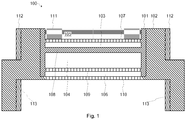
- Figure 1 shows a multi-chambered duct (100) comprising an insulating and lye-proof outer frame (102) of polypropylene and a conducting inner frame (101) encased therein.
- the inner frame (101) forms a first chamber (105) containing an air electrode (111), the first chamber (105) separated by a first partition wall (107) from a second chamber (103) filled with aerial oxygen or ionic liquid (not depicted).
- An impermeable second partition wall (108) seals the second chamber (103) from a third chamber (104) charged with zinc slurry (not depicted), which chamber in turn is divided from a fourth chamber (106) by a third partition wall (109).
- the outer frame (102) forms a perforated outer wall (110) that delimits the fourth chamber (106) and encloses the electrolyte (not depicted) flowing therethrough.
- the outer frame (102) exhibits complementarily formed regions (112, 113) that may be used for plugging the duct together with further ducts (100) of the same or similar shape and size.
- the third or fourth chamber (200) comprises energizing elements (201) for guiding the fluid flow passing through it.
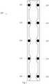
- each duct (300) exhibits an essentially uniform cross section such as the one shown in Figure 3 .
- a conductor may be extruded into stock that forms the chambers and walls therebetween, of which the first wall (107) and third wall (109) are laser-perforated.
- a gas diffusion layer (GDL) and catalysis layer are wet-laid into the first chamber (105) and compressed with each other under a given pressure, these layers now jointly constituting the air electrode (111).
- the invention is applicable throughout, inter alia , the electricity and manufacturing - especially automotive - industries.
Landscapes
- Chemical & Material Sciences (AREA)
- Chemical Kinetics & Catalysis (AREA)
- Electrochemistry (AREA)
- General Chemical & Material Sciences (AREA)
- Engineering & Computer Science (AREA)
- Manufacturing & Machinery (AREA)
- Hybrid Cells (AREA)
- Fuel Cell (AREA)
Claims (15)
- Strömungsbatterie (400) mit ineinandergesteckten Mehrkammer-Kanälen (100, 300, 401), wobei jeder Kanal eine integrierte Luftelektrode (111) enthält, Trennwänden, die teilweise ionendurchlässig perforiert und teilweise undurchlässig sind, und nichtleitenden Verbindungselementen (402) mit integrierten Durchlässen, wobei die Verbindungselemente (402) beidseitig auf die Kanäle (100, 300, 401) gesteckt sind.
- Batterie (400) nach Anspruch 1, dadurch gekennzeichnet, dass jeder Kanal einen isolierenden und laugendichten Außenrahmen (102), vorzugsweise aus Polypropylen, und einen leitenden Innenrahmen (101) umfasst, der vom Außenrahmen (102) umgeben ist.
- Batterie (400) nach Anspruch 2, dadurch gekennzeichnet, dass der Innenrahmen (101) eine erste Kammer (105) mit der Luftelektrode (111), eine zweite Kammer (103), eine dritte Kammer (104), eine vierte Kammer (106), eine teilweise perforierte erste Trennwand (107) zwischen der ersten Kammer (105) und der zweiten Kammer (103), eine undurchlässige zweite Trennwand (108) zwischen der zweiten Kammer (103) und der dritten Kammer (104) sowie eine teilweise perforierte dritte Trennwand (109) zwischen der dritten Kammer (104) und der vierten Kammer (106) bildet.
- Batterie (400) nach Anspruch 3, dadurch gekennzeichnet, dass der Außenrahmen (102) eine perforierte Außenwand (110) bildet, die die vierte Kammer (106) gegenüber der dritten Trennwand (109) begrenzt.
- Batterie (400) nach Anspruch 3 oder Anspruch 4, dadurch gekennzeichnet, dass die dritte Kammer (104) oder vierte Kammer (106) Erregungselemente (201) zum Führen oder Beeinflussen eines Fluidstroms umfasst.
- Batterie (400) nach einem der Ansprüche 3 bis 5, dadurch gekennzeichnet, dass die zweite Kammer (103) Sauerstoff, vorzugsweise Luft (403), oder lonenflüssigkeit (405) enthält.
- Batterie (400) nach einem der Ansprüche 3 bis 6, dadurch gekennzeichnet, dass die dritte Kammer (104) Metallschlamm (404) vorzugsweise auf Basis von Zink, Lithium oder Vanadium enthält.
- Batterie (400) nach einem der Ansprüche 3 bis 7, dadurch gekennzeichnet, dass die vierte Kammer (106) Elektrolyt enthält.
- Batterie (400) nach einem der Ansprüche 3 bis 8, dadurch gekennzeichnet, dass die erste Wand (107) und die dritte Wand (109) Poren aufweisen, die vorzugsweise einen Durchmesser von 50 nm bis 5 µm haben.
- Batterie (400) nach einem der vorstehenden Ansprüche, dadurch gekennzeichnet, dass jeder Kanal einen in Längsrichtung gleichmäßigen Querschnitt aufweist.
- Batterie (400) nach einem der vorstehenden Ansprüche, dadurch gekennzeichnet, dass der äußere Rahmen (102) einander ergänzend geformte Abschnitte (112, 113) zum Zusammenstecken der Kanäle (100, 300, 401) aufweist.
- Verfahren zur Herstellung einer Batterie (400) nach Anspruch 1, dadurch gekennzeichnet, dass ein Leiter so in ein Stangenmaterial extrudiert wird, dass das Stangenmaterial eine erste Kammer (105) zur Integration einer Luftelektrode (111), eine zweite Kammer (103), eine dritte Kammer (104), eine vierte Kammer (106), eine erste Trennwand (107) zwischen der ersten Kammer (105) und der zweiten Kammer (103), eine zweite Trennwand (108) zwischen der zweiten Kammer (103) und der dritten Kammer (104) und eine dritte Trennwand (109) zwischen der dritten Kammer (104) und der vierten Kammer (106) bildet, die erste Wand (107) und die dritte Wand (109) perforiert, die Luftelektrode (111) in die erste Kammer (105) integriert, das Stangenmaterial in einem laugendichten Isolator ummantelt und in Kanäle (100, 300, 401) zerlegt, die Kanäle (100, 300, 401) zusammengesteckt und Verbindungselemente (402) beidseitig auf die Kanäle (100, 300, 401) gesteckt werden.
- Verfahren nach Anspruch 12, dadurch gekennzeichnet, dass die erste Wand (107) und die dritte Wand (109) laserperforiert werden.
- Verfahren nach Anspruch 12 oder Anspruch 13, dadurch gekennzeichnet, dass die Luftelektrode (111) integriert wird, indem eine Gasdiffusionsschicht in die erste Kammer (105) nassgelegt, eine Katalyseschicht auf die Gasdiffusionsschicht nassgelegt, die Gasdiffusionsschicht mit der Katalyseschicht unter einem gegebenen Druck zur Luftelektrode (111) verdichtet und die Luftelektrode (111) gehärtet und pyrolysiert wird.
- Verwendung einer Batterie (400) nach Anspruch 1 als Strukturbauteil eines Elektrofahrzeugs, vorzugsweise als Bodenplatte eines Autos.
Priority Applications (1)
| Application Number | Priority Date | Filing Date | Title |
|---|---|---|---|
| EP16198551.0A EP3321990B1 (de) | 2016-11-13 | 2016-11-13 | Flussbatterie, herstellunsverfahren und verwendung |
Applications Claiming Priority (1)
| Application Number | Priority Date | Filing Date | Title |
|---|---|---|---|
| EP16198551.0A EP3321990B1 (de) | 2016-11-13 | 2016-11-13 | Flussbatterie, herstellunsverfahren und verwendung |
Publications (2)
| Publication Number | Publication Date |
|---|---|
| EP3321990A1 EP3321990A1 (de) | 2018-05-16 |
| EP3321990B1 true EP3321990B1 (de) | 2019-10-09 |
Family
ID=57288266
Family Applications (1)
| Application Number | Title | Priority Date | Filing Date |
|---|---|---|---|
| EP16198551.0A Active EP3321990B1 (de) | 2016-11-13 | 2016-11-13 | Flussbatterie, herstellunsverfahren und verwendung |
Country Status (1)
| Country | Link |
|---|---|
| EP (1) | EP3321990B1 (de) |
Families Citing this family (1)
| Publication number | Priority date | Publication date | Assignee | Title |
|---|---|---|---|---|
| US11367915B2 (en) | 2018-02-12 | 2022-06-21 | Hilabs Inc. | Flow battery, process for the manufacture, and use thereof |
Family Cites Families (4)
| Publication number | Priority date | Publication date | Assignee | Title |
|---|---|---|---|---|
| US4714662A (en) * | 1986-05-12 | 1987-12-22 | Gould Inc. | Power module assembly of electrochemical cells |
| US5445901A (en) * | 1994-03-15 | 1995-08-29 | Electric Fuel (E.F.L.) Ltd. | Zinc-oxygen battery |
| US20140255812A1 (en) * | 2013-03-08 | 2014-09-11 | Global Energy Science, Llc (A California Limited Liability Company) | Taylor vortex flow electrochemical cells utilizing particulate electrolyte suspensions |
| KR101471886B1 (ko) | 2013-07-16 | 2014-12-10 | 주식회사 에이치투 | 전해질용 관을 포함하는 레독스 흐름 전지용스택 |
-
2016
- 2016-11-13 EP EP16198551.0A patent/EP3321990B1/de active Active
Non-Patent Citations (1)
| Title |
|---|
| None * |
Also Published As
| Publication number | Publication date |
|---|---|
| EP3321990A1 (de) | 2018-05-16 |
Similar Documents
| Publication | Publication Date | Title |
|---|---|---|
| US11824243B2 (en) | Electrode assembly and flow battery with improved electrolyte distribution | |
| US9203123B2 (en) | Lithium accumulator | |
| US20130189592A1 (en) | Part solid, part fluid and flow electrochemical cells including metal-air and li-air battery systems | |
| US8003278B2 (en) | Fuel cell | |
| US12266837B2 (en) | Sealed redox battery | |
| AU2014361750A1 (en) | Electrochemical cells and components thereof | |
| EP3046171A1 (de) | Brennstoffzelle und brennstoffzellenstapel | |
| US20220085399A1 (en) | Fuel cell and fuel cell system for an aircraft | |
| US20240039026A1 (en) | Systems and methods for electrode assembly for redox flow battery system | |
| US20220238904A1 (en) | Redox flow battery | |
| KR20160107608A (ko) | 격자형 흐름전극구조체 | |
| KR20160136266A (ko) | 격자형 흐름전극구조체 | |
| CN102598385B (zh) | 燃料电池 | |
| US11367915B2 (en) | Flow battery, process for the manufacture, and use thereof | |
| KR20080106839A (ko) | 분말형 연료 전지 | |
| EP3321990A1 (de) | Flussbatterie, verfahren zur herstellung und verwendung derselben | |
| KR101637008B1 (ko) | 활성점에 차이가 있는 카본펠트 및 이를 포함하는 레독스 흐름 이차전지 | |
| JP2005183132A (ja) | 燃料電池 | |
| KR102278869B1 (ko) | 신규 모듈식 전기화학 전지 및 스택 설계 | |
| WO2014062482A1 (en) | Oxygen plenum configurations of components in low cost planar rechargeable oxide-ion battery (rob) cells and stacks | |
| EP2037520A1 (de) | Rohrartige brennstoffzelle | |
| US20240191031A1 (en) | Method for preparing polybenzimidazole-based separator, polybenzimidazole-based separator prepared thereby, and secondary battery including the same | |
| CN202050021U (zh) | 一种非流动型钒素二次电池 | |
| Park et al. | Cell for Flow Battery | |
| JP2006216465A (ja) | 燃料電池 |
Legal Events
| Date | Code | Title | Description |
|---|---|---|---|
| PUAI | Public reference made under article 153(3) epc to a published international application that has entered the european phase |
Free format text: ORIGINAL CODE: 0009012 |
|
| STAA | Information on the status of an ep patent application or granted ep patent |
Free format text: STATUS: THE APPLICATION HAS BEEN PUBLISHED |
|
| AK | Designated contracting states |
Kind code of ref document: A1 Designated state(s): AL AT BE BG CH CY CZ DE DK EE ES FI FR GB GR HR HU IE IS IT LI LT LU LV MC MK MT NL NO PL PT RO RS SE SI SK SM TR |
|
| AX | Request for extension of the european patent |
Extension state: BA ME |
|
| STAA | Information on the status of an ep patent application or granted ep patent |
Free format text: STATUS: REQUEST FOR EXAMINATION WAS MADE |
|
| 17P | Request for examination filed |
Effective date: 20181116 |
|
| RAV | Requested validation state of the european patent: fee paid |
Extension state: MA Effective date: 20181116 Extension state: MD Effective date: 20181116 |
|
| RAX | Requested extension states of the european patent have changed |
Extension state: BA Payment date: 20181116 Extension state: ME Payment date: 20181116 |
|
| RBV | Designated contracting states (corrected) |
Designated state(s): AL AT BE BG CH CY CZ DE DK EE ES FI FR GB GR HR HU IE IS IT LI LT LU LV MC MK MT NL NO PL PT RO RS SE SI SK SM TR |
|
| RIC1 | Information provided on ipc code assigned before grant |
Ipc: H01M 4/86 20060101ALN20181218BHEP Ipc: H01M 12/06 20060101ALI20181218BHEP Ipc: H01M 12/08 20060101ALI20181218BHEP Ipc: H01M 4/88 20060101ALN20181218BHEP Ipc: H01M 2/02 20060101AFI20181218BHEP |
|
| GRAP | Despatch of communication of intention to grant a patent |
Free format text: ORIGINAL CODE: EPIDOSNIGR1 |
|
| STAA | Information on the status of an ep patent application or granted ep patent |
Free format text: STATUS: GRANT OF PATENT IS INTENDED |
|
| INTG | Intention to grant announced |
Effective date: 20190227 |
|
| RAP1 | Party data changed (applicant data changed or rights of an application transferred) |
Owner name: HILABS GMBH |
|
| RIN1 | Information on inventor provided before grant (corrected) |
Inventor name: HAQ, MANAN |
|
| GRAS | Grant fee paid |
Free format text: ORIGINAL CODE: EPIDOSNIGR3 |
|
| GRAA | (expected) grant |
Free format text: ORIGINAL CODE: 0009210 |
|
| STAA | Information on the status of an ep patent application or granted ep patent |
Free format text: STATUS: THE PATENT HAS BEEN GRANTED |
|
| AK | Designated contracting states |
Kind code of ref document: B1 Designated state(s): AL AT BE BG CH CY CZ DE DK EE ES FI FR GB GR HR HU IE IS IT LI LT LU LV MC MK MT NL NO PL PT RO RS SE SI SK SM TR |
|
| AX | Request for extension of the european patent |
Extension state: BA ME |
|
| REG | Reference to a national code |
Ref country code: GB Ref legal event code: FG4D |
|
| REG | Reference to a national code |
Ref country code: CH Ref legal event code: EP |
|
| REG | Reference to a national code |
Ref country code: DE Ref legal event code: R096 Ref document number: 602016022028 Country of ref document: DE |
|
| REG | Reference to a national code |
Ref country code: IE Ref legal event code: FG4D |
|
| REG | Reference to a national code |
Ref country code: AT Ref legal event code: REF Ref document number: 1189848 Country of ref document: AT Kind code of ref document: T Effective date: 20191115 |
|
| REG | Reference to a national code |
Ref country code: NL Ref legal event code: FP |
|
| REG | Reference to a national code |
Ref country code: CH Ref legal event code: NV Representative=s name: TR-IP CONSULTING LLC, CH |
|
| REG | Reference to a national code |
Ref country code: CH Ref legal event code: PCAR Free format text: NEW ADDRESS: ROUTE DU COUTSET 18, 1485 NUVILLY (CH) |
|
| REG | Reference to a national code |
Ref country code: LT Ref legal event code: MG4D |
|
| PG25 | Lapsed in a contracting state [announced via postgrant information from national office to epo] |
Ref country code: FI Free format text: LAPSE BECAUSE OF FAILURE TO SUBMIT A TRANSLATION OF THE DESCRIPTION OR TO PAY THE FEE WITHIN THE PRESCRIBED TIME-LIMIT Effective date: 20191009 Ref country code: BG Free format text: LAPSE BECAUSE OF FAILURE TO SUBMIT A TRANSLATION OF THE DESCRIPTION OR TO PAY THE FEE WITHIN THE PRESCRIBED TIME-LIMIT Effective date: 20200109 Ref country code: LT Free format text: LAPSE BECAUSE OF FAILURE TO SUBMIT A TRANSLATION OF THE DESCRIPTION OR TO PAY THE FEE WITHIN THE PRESCRIBED TIME-LIMIT Effective date: 20191009 Ref country code: PL Free format text: LAPSE BECAUSE OF FAILURE TO SUBMIT A TRANSLATION OF THE DESCRIPTION OR TO PAY THE FEE WITHIN THE PRESCRIBED TIME-LIMIT Effective date: 20191009 Ref country code: NO Free format text: LAPSE BECAUSE OF FAILURE TO SUBMIT A TRANSLATION OF THE DESCRIPTION OR TO PAY THE FEE WITHIN THE PRESCRIBED TIME-LIMIT Effective date: 20200109 Ref country code: SE Free format text: LAPSE BECAUSE OF FAILURE TO SUBMIT A TRANSLATION OF THE DESCRIPTION OR TO PAY THE FEE WITHIN THE PRESCRIBED TIME-LIMIT Effective date: 20191009 Ref country code: LV Free format text: LAPSE BECAUSE OF FAILURE TO SUBMIT A TRANSLATION OF THE DESCRIPTION OR TO PAY THE FEE WITHIN THE PRESCRIBED TIME-LIMIT Effective date: 20191009 Ref country code: PT Free format text: LAPSE BECAUSE OF FAILURE TO SUBMIT A TRANSLATION OF THE DESCRIPTION OR TO PAY THE FEE WITHIN THE PRESCRIBED TIME-LIMIT Effective date: 20200210 Ref country code: ES Free format text: LAPSE BECAUSE OF FAILURE TO SUBMIT A TRANSLATION OF THE DESCRIPTION OR TO PAY THE FEE WITHIN THE PRESCRIBED TIME-LIMIT Effective date: 20191009 Ref country code: GR Free format text: LAPSE BECAUSE OF FAILURE TO SUBMIT A TRANSLATION OF THE DESCRIPTION OR TO PAY THE FEE WITHIN THE PRESCRIBED TIME-LIMIT Effective date: 20200110 |
|
| PG25 | Lapsed in a contracting state [announced via postgrant information from national office to epo] |
Ref country code: HR Free format text: LAPSE BECAUSE OF FAILURE TO SUBMIT A TRANSLATION OF THE DESCRIPTION OR TO PAY THE FEE WITHIN THE PRESCRIBED TIME-LIMIT Effective date: 20191009 Ref country code: RS Free format text: LAPSE BECAUSE OF FAILURE TO SUBMIT A TRANSLATION OF THE DESCRIPTION OR TO PAY THE FEE WITHIN THE PRESCRIBED TIME-LIMIT Effective date: 20191009 Ref country code: IS Free format text: LAPSE BECAUSE OF FAILURE TO SUBMIT A TRANSLATION OF THE DESCRIPTION OR TO PAY THE FEE WITHIN THE PRESCRIBED TIME-LIMIT Effective date: 20200224 |
|
| PG25 | Lapsed in a contracting state [announced via postgrant information from national office to epo] |
Ref country code: AL Free format text: LAPSE BECAUSE OF FAILURE TO SUBMIT A TRANSLATION OF THE DESCRIPTION OR TO PAY THE FEE WITHIN THE PRESCRIBED TIME-LIMIT Effective date: 20191009 |
|
| REG | Reference to a national code |
Ref country code: DE Ref legal event code: R097 Ref document number: 602016022028 Country of ref document: DE |
|
| PG2D | Information on lapse in contracting state deleted |
Ref country code: IS |
|
| PG25 | Lapsed in a contracting state [announced via postgrant information from national office to epo] |
Ref country code: IS Free format text: LAPSE BECAUSE OF FAILURE TO SUBMIT A TRANSLATION OF THE DESCRIPTION OR TO PAY THE FEE WITHIN THE PRESCRIBED TIME-LIMIT Effective date: 20200209 Ref country code: CZ Free format text: LAPSE BECAUSE OF FAILURE TO SUBMIT A TRANSLATION OF THE DESCRIPTION OR TO PAY THE FEE WITHIN THE PRESCRIBED TIME-LIMIT Effective date: 20191009 Ref country code: RO Free format text: LAPSE BECAUSE OF FAILURE TO SUBMIT A TRANSLATION OF THE DESCRIPTION OR TO PAY THE FEE WITHIN THE PRESCRIBED TIME-LIMIT Effective date: 20191009 Ref country code: MC Free format text: LAPSE BECAUSE OF FAILURE TO SUBMIT A TRANSLATION OF THE DESCRIPTION OR TO PAY THE FEE WITHIN THE PRESCRIBED TIME-LIMIT Effective date: 20191009 Ref country code: DK Free format text: LAPSE BECAUSE OF FAILURE TO SUBMIT A TRANSLATION OF THE DESCRIPTION OR TO PAY THE FEE WITHIN THE PRESCRIBED TIME-LIMIT Effective date: 20191009 Ref country code: LU Free format text: LAPSE BECAUSE OF NON-PAYMENT OF DUE FEES Effective date: 20191113 Ref country code: EE Free format text: LAPSE BECAUSE OF FAILURE TO SUBMIT A TRANSLATION OF THE DESCRIPTION OR TO PAY THE FEE WITHIN THE PRESCRIBED TIME-LIMIT Effective date: 20191009 |
|
| PLBE | No opposition filed within time limit |
Free format text: ORIGINAL CODE: 0009261 |
|
| STAA | Information on the status of an ep patent application or granted ep patent |
Free format text: STATUS: NO OPPOSITION FILED WITHIN TIME LIMIT |
|
| PG25 | Lapsed in a contracting state [announced via postgrant information from national office to epo] |
Ref country code: SK Free format text: LAPSE BECAUSE OF FAILURE TO SUBMIT A TRANSLATION OF THE DESCRIPTION OR TO PAY THE FEE WITHIN THE PRESCRIBED TIME-LIMIT Effective date: 20191009 Ref country code: SM Free format text: LAPSE BECAUSE OF FAILURE TO SUBMIT A TRANSLATION OF THE DESCRIPTION OR TO PAY THE FEE WITHIN THE PRESCRIBED TIME-LIMIT Effective date: 20191009 |
|
| VS25 | Lapsed in a validation state [announced via postgrant information from nat. office to epo] |
Ref country code: MD Free format text: LAPSE BECAUSE OF FAILURE TO SUBMIT A TRANSLATION OF THE DESCRIPTION OR TO PAY THE FEE WITHIN THE PRESCRIBED TIME-LIMIT Effective date: 20191009 |
|
| 26N | No opposition filed |
Effective date: 20200710 |
|
| REG | Reference to a national code |
Ref country code: DE Ref legal event code: R079 Ref document number: 602016022028 Country of ref document: DE Free format text: PREVIOUS MAIN CLASS: H01M0002020000 Ipc: H01M0050100000 |
|
| PG25 | Lapsed in a contracting state [announced via postgrant information from national office to epo] |
Ref country code: SI Free format text: LAPSE BECAUSE OF FAILURE TO SUBMIT A TRANSLATION OF THE DESCRIPTION OR TO PAY THE FEE WITHIN THE PRESCRIBED TIME-LIMIT Effective date: 20191009 |
|
| REG | Reference to a national code |
Ref country code: AT Ref legal event code: UEP Ref document number: 1189848 Country of ref document: AT Kind code of ref document: T Effective date: 20191009 |
|
| PG25 | Lapsed in a contracting state [announced via postgrant information from national office to epo] |
Ref country code: CY Free format text: LAPSE BECAUSE OF FAILURE TO SUBMIT A TRANSLATION OF THE DESCRIPTION OR TO PAY THE FEE WITHIN THE PRESCRIBED TIME-LIMIT Effective date: 20191009 |
|
| VS25 | Lapsed in a validation state [announced via postgrant information from nat. office to epo] |
Ref country code: MA Free format text: LAPSE BECAUSE OF FAILURE TO SUBMIT A TRANSLATION OF THE DESCRIPTION OR TO PAY THE FEE WITHIN THE PRESCRIBED TIME-LIMIT Effective date: 20191009 |
|
| PG25 | Lapsed in a contracting state [announced via postgrant information from national office to epo] |
Ref country code: HU Free format text: LAPSE BECAUSE OF FAILURE TO SUBMIT A TRANSLATION OF THE DESCRIPTION OR TO PAY THE FEE WITHIN THE PRESCRIBED TIME-LIMIT; INVALID AB INITIO Effective date: 20161113 |
|
| PG25 | Lapsed in a contracting state [announced via postgrant information from national office to epo] |
Ref country code: TR Free format text: LAPSE BECAUSE OF FAILURE TO SUBMIT A TRANSLATION OF THE DESCRIPTION OR TO PAY THE FEE WITHIN THE PRESCRIBED TIME-LIMIT Effective date: 20191009 |
|
| PG25 | Lapsed in a contracting state [announced via postgrant information from national office to epo] |
Ref country code: MK Free format text: LAPSE BECAUSE OF FAILURE TO SUBMIT A TRANSLATION OF THE DESCRIPTION OR TO PAY THE FEE WITHIN THE PRESCRIBED TIME-LIMIT Effective date: 20191009 |
|
| PGFP | Annual fee paid to national office [announced via postgrant information from national office to epo] |
Ref country code: NL Payment date: 20230816 Year of fee payment: 8 |
|
| PGFP | Annual fee paid to national office [announced via postgrant information from national office to epo] |
Ref country code: IE Payment date: 20230816 Year of fee payment: 8 Ref country code: GB Payment date: 20230914 Year of fee payment: 8 |
|
| PGFP | Annual fee paid to national office [announced via postgrant information from national office to epo] |
Ref country code: FR Payment date: 20230821 Year of fee payment: 8 Ref country code: BE Payment date: 20230816 Year of fee payment: 8 |
|
| PGFP | Annual fee paid to national office [announced via postgrant information from national office to epo] |
Ref country code: MT Payment date: 20230817 Year of fee payment: 8 |
|
| PGFP | Annual fee paid to national office [announced via postgrant information from national office to epo] |
Ref country code: CH Payment date: 20231202 Year of fee payment: 8 Ref country code: AT Payment date: 20230904 Year of fee payment: 8 |
|
| REG | Reference to a national code |
Ref country code: CH Ref legal event code: PL |
|
| REG | Reference to a national code |
Ref country code: NL Ref legal event code: MM Effective date: 20241201 |
|
| REG | Reference to a national code |
Ref country code: AT Ref legal event code: MM01 Ref document number: 1189848 Country of ref document: AT Kind code of ref document: T Effective date: 20241113 Ref country code: CH Ref legal event code: PL |
|
| GBPC | Gb: european patent ceased through non-payment of renewal fee |
Effective date: 20241113 |
|
| PG25 | Lapsed in a contracting state [announced via postgrant information from national office to epo] |
Ref country code: CH Free format text: LAPSE BECAUSE OF NON-PAYMENT OF DUE FEES Effective date: 20241130 |
|
| PG25 | Lapsed in a contracting state [announced via postgrant information from national office to epo] |
Ref country code: AT Free format text: LAPSE BECAUSE OF NON-PAYMENT OF DUE FEES Effective date: 20241113 |
|
| PG25 | Lapsed in a contracting state [announced via postgrant information from national office to epo] |
Ref country code: NL Free format text: LAPSE BECAUSE OF NON-PAYMENT OF DUE FEES Effective date: 20241201 |
|
| REG | Reference to a national code |
Ref country code: BE Ref legal event code: MM Effective date: 20241130 |
|
| PG25 | Lapsed in a contracting state [announced via postgrant information from national office to epo] |
Ref country code: BE Free format text: LAPSE BECAUSE OF NON-PAYMENT OF DUE FEES Effective date: 20241130 Ref country code: GB Free format text: LAPSE BECAUSE OF NON-PAYMENT OF DUE FEES Effective date: 20241113 |
|
| PG25 | Lapsed in a contracting state [announced via postgrant information from national office to epo] |
Ref country code: FR Free format text: LAPSE BECAUSE OF NON-PAYMENT OF DUE FEES Effective date: 20241130 |
|
| PG25 | Lapsed in a contracting state [announced via postgrant information from national office to epo] |
Ref country code: IE Free format text: LAPSE BECAUSE OF NON-PAYMENT OF DUE FEES Effective date: 20241113 |
|
| PGFP | Annual fee paid to national office [announced via postgrant information from national office to epo] |
Ref country code: DE Payment date: 20251103 Year of fee payment: 10 |
|
| PGFP | Annual fee paid to national office [announced via postgrant information from national office to epo] |
Ref country code: IT Payment date: 20251031 Year of fee payment: 10 |