EP3321901A1 - Distributed optical fiber perimeter security system, and sound restoration system and method - Google Patents
Distributed optical fiber perimeter security system, and sound restoration system and method Download PDFInfo
- Publication number
- EP3321901A1 EP3321901A1 EP16840733.6A EP16840733A EP3321901A1 EP 3321901 A1 EP3321901 A1 EP 3321901A1 EP 16840733 A EP16840733 A EP 16840733A EP 3321901 A1 EP3321901 A1 EP 3321901A1
- Authority
- EP
- European Patent Office
- Prior art keywords
- optical fiber
- signal
- sensing
- interference
- sound
- Prior art date
- Legal status (The legal status is an assumption and is not a legal conclusion. Google has not performed a legal analysis and makes no representation as to the accuracy of the status listed.)
- Granted
Links
Images

Classifications
-
- G—PHYSICS
- G01—MEASURING; TESTING
- G01H—MEASUREMENT OF MECHANICAL VIBRATIONS OR ULTRASONIC, SONIC OR INFRASONIC WAVES
- G01H9/00—Measuring mechanical vibrations or ultrasonic, sonic or infrasonic waves by using radiation-sensitive means, e.g. optical means
- G01H9/004—Measuring mechanical vibrations or ultrasonic, sonic or infrasonic waves by using radiation-sensitive means, e.g. optical means using fibre optic sensors
-
- G—PHYSICS
- G08—SIGNALLING
- G08B—SIGNALLING OR CALLING SYSTEMS; ORDER TELEGRAPHS; ALARM SYSTEMS
- G08B13/00—Burglar, theft or intruder alarms
-
- G—PHYSICS
- G08—SIGNALLING
- G08B—SIGNALLING OR CALLING SYSTEMS; ORDER TELEGRAPHS; ALARM SYSTEMS
- G08B13/00—Burglar, theft or intruder alarms
- G08B13/02—Mechanical actuation
- G08B13/12—Mechanical actuation by the breaking or disturbance of stretched cords or wires
- G08B13/122—Mechanical actuation by the breaking or disturbance of stretched cords or wires for a perimeter fence
- G08B13/124—Mechanical actuation by the breaking or disturbance of stretched cords or wires for a perimeter fence with the breaking or disturbance being optically detected, e.g. optical fibers in the perimeter fence
-
- G—PHYSICS
- G08—SIGNALLING
- G08B—SIGNALLING OR CALLING SYSTEMS; ORDER TELEGRAPHS; ALARM SYSTEMS
- G08B13/00—Burglar, theft or intruder alarms
- G08B13/16—Actuation by interference with mechanical vibrations in air or other fluid
- G08B13/1654—Actuation by interference with mechanical vibrations in air or other fluid using passive vibration detection systems
- G08B13/1672—Actuation by interference with mechanical vibrations in air or other fluid using passive vibration detection systems using sonic detecting means, e.g. a microphone operating in the audio frequency range
-
- G—PHYSICS
- G08—SIGNALLING
- G08B—SIGNALLING OR CALLING SYSTEMS; ORDER TELEGRAPHS; ALARM SYSTEMS
- G08B13/00—Burglar, theft or intruder alarms
- G08B13/18—Actuation by interference with heat, light, or radiation of shorter wavelength; Actuation by intruding sources of heat, light, or radiation of shorter wavelength
- G08B13/181—Actuation by interference with heat, light, or radiation of shorter wavelength; Actuation by intruding sources of heat, light, or radiation of shorter wavelength using active radiation detection systems
- G08B13/183—Actuation by interference with heat, light, or radiation of shorter wavelength; Actuation by intruding sources of heat, light, or radiation of shorter wavelength using active radiation detection systems by interruption of a radiation beam or barrier
- G08B13/186—Actuation by interference with heat, light, or radiation of shorter wavelength; Actuation by intruding sources of heat, light, or radiation of shorter wavelength using active radiation detection systems by interruption of a radiation beam or barrier using light guides, e.g. optical fibres
Definitions
- the present disclosure relates to the field of security technologies, and in particular, relates to a sound restoration system, a sound restoration method, and a distributed optical fiber perimeter security system.
- Optical fibers are not merely used to transmit signals, and are also used as sensors when being employed to sensing applications.
- ambient interference is propagated to the optical fibers, features or properties of optical signals transmitted over the optical fibers will be partially changed.
- a dedicated sensing instrument is configured to be capable of monitoring interference causing variations of the features or properties of the optical signals such as attenuation, phase, wavelength, polarization, mode field distribution and propagation time. By means of modulation of the optical signals, measurements of various events and states become possible.
- a distributed optical fiber perimeter security system is a distributed sensing system that uses the optical fiber as a sensing and transmission medium. Within a region in which the sensing optical fibers are arranged, the optical fiber perimeter security system is capable of monitoring, remotely and in real time, sudden events such as intrusion behaviors in a specific precision range.
- the optical fiber perimeter security system may be applied to perimeter security supervision in prisons, important military targets, arsenals, railings along railways and the like, and may also be applied to perimeter security supervision in residential blocks, government organs, nuclear power plants, airports and the like important facilities.
- a conventional distributed optical fiber perimeter security system divides the perimeter into several small monitoring areas (which are also referred to as protection areas), and each protection area is monitored by one optical fiber sensing unit.
- This optical fiber sensing unit generally has no positioning capability, and is only capable of sensing and transmitting intrusion vibration signals and judging whether an intrusion event occurs.
- a plurality of optical fiber sensing units construct a network, such that it may judge an intrusion event occurs in which protection area, thereby achieving the objective of positioning.
- the present disclosure is intended to provide a sound restoration system having a sound restoration capability, a sound restoration method, and a distributed optical fiber perimeter security system, so as to overcome, at least to some extent, one or more problems caused by restrictions and defects in the related arts.
- a sound restoration system which is applied to a distributed optical fiber perimeter security system which monitors several protection areas.
- the sound restoration system includes:
- the audio output mechanism is configured to restore the audio signal based on a light intensity of the interference signal.
- the optical fiber Michelson interference mechanism includes:
- I a light intensity of the interference signal
- I 1 and I 2 respectively represent light intensities of the optical signals in the reference arm and the sensing arm and ⁇ ⁇ ⁇ represents a phase difference therebetween
- n represents an effective refractive index of the sensing optical fiber
- ⁇ represents an incident wavelength of the input optical signal
- P 12 and P 11 represent Pockel constants
- v represents a Poisson's ratio
- ⁇ 3 represents an axial length variation rate of the sensing arm
- L represents a vibration length
- k represents an inherent parameter of the sensing optical fiber
- p represents a sound pressure when the sound signal is applied to the sensing arm.
- the front-end device includes an optical fiber coupler.
- the rear-end device includes a Faraday rotator mirror or a reflective mirror.
- the sensing optical fiber is configured to at least partially multiplex an intrusion-sensing optical fiber in the distributed optical fiber perimeter security system.
- the sensing optical fiber is arranged in a mesh shape, a spiral shape or a straight line shape.
- the audio output mechanism includes:
- the audio output mechanism further includes: a demodulation unit, configured to demodulate the audio signal to play and/or store a sound corresponding to the audio signal.
- a distributed optical fiber perimeter security system includes:
- the intrusion sensing system includes an optical fiber configured to sense and transmit the intrusion vibration signals, a sensing optical fiber of the optical fiber Michelson interference mechanism at least partially multiplexing the optical fiber.
- a sound restoration method which is applied to a distributed optical fiber perimeter security system which monitors several protection areas.
- the sound restoration method includes:
- the audio signal is restored based on a light intensity of the interference signal.
- I a light intensity of the interference signal
- the optical fiber Michelson interference mechanism includes a sensing optical fiber having a reference arm and a sensing arm
- I 1 and I 2 respectively represent light intensities of the optical signals in the reference arm and the sensing arm and ⁇ ⁇ represents a phase difference therebetween
- n represents an effective refractive index of the sensing optical fiber
- ⁇ represents an incident wavelength of the input optical signal
- P 12 and P 11 represent Pockel constants
- v a Poisson's ratio
- ⁇ 3 represents an axial length variation rate of the sensing arm
- L represents a vibration length
- k an inherent parameter of the sensing optical fiber
- p represents a
- interference signals generated based on the sound pressures of audio signals of a plurality of protection areas are acquired, and when an alarm signal of any of the protection areas is received, an audio signal restored based on the interference signal of the protection area is output.
- the sound restoration system outputs the corresponding audio signal only when the alarm signal is received, which in one aspect prevents interference caused to user's judgment and in another aspect saves system resources.
- this exemplary embodiment firstly provides a sound restoration system.
- the sound restoration system is applied to the distributed optical fiber perimeter security system which monitors a plurality of protection areas.
- the distributed optical fiber perimeter security system is capable of monitoring eight protection areas, and the sound restoration system may mainly include a laser generation mechanism 11, a beam splitting mechanism 12, a plurality of optical fiber Michelson interference mechanisms 13, and an audio output mechanism 14.
- the sound restoration system may mainly include a laser generation mechanism 11, a beam splitting mechanism 12, a plurality of optical fiber Michelson interference mechanisms 13, and an audio output mechanism 14.
- a person skilled in the art would also configure other structures such as a power supply, a control component, a signal optimization component and the like according to actual needs.
- the laser generation mechanism 11 is mainly configured to provide a laser signal.
- the laser generation mechanism 11 is preferably a semiconductor distributed feedback laser (DFB) light source, thereby to improve ambient interference resistance capability of the system and improve signal-to-noise ratio of the entire system.
- the beam splitting mechanism 12 is mainly configured to split the laser signal into a plurality of input optical signal, and thus correspondingly provide the optical signals to the optical fiber Michelson interference mechanisms 13.
- the beam splitting mechanism 12 may be a beam splitter known in the prior art.
- other optical elements such as an isolator, a circulator and the like may be configured, which are not specifically limited in this exemplary embodiment.
- the optical fiber Michelson interference mechanism is mainly configured to receive an input optical signal, and under effect of a sound pressure generated by a surrounding audio signal, output an interference signal carrying sound pressure information generated by the audio signal.
- the optical fiber Michelson interference mechanism 13 has the advantages of high use security and reliability, strong interference resistance capability and long transmission distance, and thus is very applicable to the sound restoration system in this exemplary embodiment.
- the beam splitting mechanism 12 splits the laser signal into eight input optical signals, and totally eight optical fiber Michelson interference mechanisms 13 are configured.
- Each optical fiber Michelson interference mechanism 13 corresponds to and is arranged at one of the protection areas, such that the interference signal carrying sound pressure information generated by the audio signal of the corresponding protection area is acquired.
- the audio output mechanism 14 is mainly configured to receive the interference signals, and when an alarm signal of any of the protection areas is received, output an audio signal restored based on the interference signal of the protection area.
- the audio output mechanism 14 is mainly configured to receive the eight interference signals, output an audio signal restored based on the interference signal of a protection area 2 upon receiving an alarm signal of the protection area 2, and output an audio signal restored based on the interference signal of a protection area 7 upon receiving an alarm signal of the protection area 7, and the like.
- the sound restoration system In the sound restoration system, interference signals generated based on the sound pressures of audio signals of a plurality of protection areas are acquired, and when an alarm signal of any of the protection areas is received, an audio signal restored based on the interference signal of the protection area is output. In this way, a user is facilitated to further make an accurate judgment on whether an abnormal event such as an intrusion behavior occurs, thereby greatly improving the user's capability in identifying abnormal events, and thus timely knowing abnormal conditions and abnormal situations, and reducing false alarms.
- the sound restoration system outputs the corresponding audio signal only when the alarm signal is received, which in one aspect prevents interference caused to user's judgment and in another aspect saves system resources.
- the optical fiber Michelson interference mechanism 13 may include a sensing optical fiber 131, a front-end device 132, a rear-end device 133 and an photodetector 134.
- the sensing optical fiber 131 has a reference arm and a sensing arm.
- the front-end device 132 is configured to receive the input optical signal, and transmit the input optical signal from a first end of the sensing optical fiber 131 to the reference arm and the sensing arm.
- the rear-end device 133 is configured to feed back the input optical signal from a second end of the sensing optical fiber 131 to the first end of the sensing optical fiber 131 so as to form an interference signal.
- the photodetector 134 is arranged at the first end of the sensing optical fiber 131, and configured to receive the interference signal, and output it after a photoelectric conversion.
- the front-end device 132 may include an optical fiber coupler
- the rear-end device 133 may include a Faraday rotator mirror (FRM) or a reflective mirror.
- the optical fiber coupler is configured to receive an input beam, and uniformly couple the input beam to the reference arm and the sensing arm of the sensing optical fiber 131.
- the input beam in the reference arm and the sensing arm after reaching a second end of the sensing optical fiber 131, is reflected by the reflective mirror or the Faraday rotator mirror arranged at the second end of the sensing optical fiber 131 back to the reference arm and the sensing arm of the sensing optical fiber 131, to respectively form a reference light and a signal light.
- the reference light and the signal light form an interference signal in the optical fiber coupler, the interference signal is received by the photodetector 134, and is output to the audio output mechanism 14 after being photoelectrically converted.
- the sensing optical fiber 131 may partially or totally multiplex the original transmission optical fiber of the distributed optical fiber perimeter security system, for example, the transmission optical fiber originally configured to sense and transmit intrusion vibration signals. In this way, there is no need to newly provide the sensing optical fiber 131, or may prevent extra sensing optical fibers 131, and thus to lower implementation cost of the system.
- the sensing optical fiber 131 may be arranged in a mesh shape or a spiral shape. In this way, in one aspect, the interference signals may be more uniformly acquired, and in another aspect, a longer sensing optical fiber 131 improves sensing sensitivity of the system.
- the rear-end device 133 is preferably a Faraday rotator mirror, for example, a 45-degree Faraday rotator mirror configured at a tail end of the reference arm and the sensing arm.
- a Faraday rotator mirror for example, a 45-degree Faraday rotator mirror configured at a tail end of the reference arm and the sensing arm.
- the audio output mechanism 14 may restore the audio signal based on the light intensity of the interference signal. For example:
- ⁇ ⁇ n 2 ⁇ ⁇ L 1 ⁇ 1 2 n 2 1 ⁇ v P 12 ⁇ v P 11 ⁇ 3
- n an effective refractive index of the sensing optical fiber 131
- ⁇ an incident wavelength of the input optical signal
- P 12 and P 11 Pockel constants
- v a Poisson's ratio
- ⁇ 3 an axial length variation rate of the sensing arm
- ⁇ 3 ⁇ L / L
- L represents a vibration length
- ⁇ L represents an axial deformation.
- the light intensity of the interference signal output by the optical fiber Michelson interference mechanism 13 is proportional to the ambient sound pressure. Therefore, the audio signals at site may be directly restored based on the interference signal output by the optical fiber Michelson interference mechanism 13.
- the audio output mechanism 14 may include a processing unit 141, a control unit 142 and a gating unit 143.
- the processing unit 141 is configured to restore an audio signal of any of the protection areas based on the interference signal of the protection area.
- the control unit 142 is configured to output a control signal upon receiving an alarm signal from any of the protection areas, wherein the control signal at least includes information of the protection area from which the alarm signal is sent.
- the gating unit 143 is connected to the control unit 142 and the processing unit 141, and configured to output, upon receiving the control signal and based on the control signal, the audio signal of the protection area from which the alarm signal is sent.
- the audio output mechanism 14 may further include a demodulation unit 144.
- the demodulation unit 144 is configured to demodulate the audio signal to play and store a sound corresponding to the audio signal.
- the processing unit 141 may start to restore the audio signal of a protection area from the interference signal of the protection area after receiving an alarm signal of the protection area, and then output the audio signal to the control unit 142, which is not limited by the implementation in this exemplary embodiment.
- the processing unit 141 may be a signal processing circuit
- the gating unit 143 may be a single-chip microcomputer gating circuit
- the control unit 142 may be an industrial computer.
- the interference signals of eight protection areas enter a signal processing circuit after being photoelectrically converted by the photodetector 134, and after the interference signals are processed, such as being filtered and regulated, via the signal processing circuit, the audio signals are demodulated, and eight audio signals are output to the single-chip microcomputer gating circuit.
- the industrial computer Upon receiving an alarm signal sent from any of the protection areas (the alarm signal may also be generated by the industrial computer itself), the industrial computer sends a control signal at least including information of the protection area to the single-chip microcomputer gating circuit, whereupon the single-chip microcomputer gating circuit gates the audio signal of the protection area and then output the audio signal to the industrial computer.
- the demodulation unit 144 may be demodulation software installed on the industrial computer. After the audio signal of the protection area is input into the industrial computer, the audio signal is demodulated via the demodulation software to play and store the corresponding sound. In addition, the user may set such parameters as play time, storage time and the like of the sound via the demodulation software.
- the processing unit, gating unit and control unit are illustrated by using specific hardware as an example, but they may also be implemented by using software or hardware in other types; likewise, the demodulation unit may also be implemented in other manners such as hardware; in addition, any combination of the processing unit, gating unit, control unit and demodulation unit may be integrated into a function module or component, which is not specifically limited in this exemplary embodiment.
- the distributed optical fiber perimeter security system mainly includes an intrusion sensing system and any of the sound restoration system as described above.
- the security system may further include an alarming unit and other components.
- the intrusion sensing system is configured to acquire intrusion vibration signals of a plurality of protection areas.
- the alarming unit judges, based on the intrusion vibration signals, whether an abnormal event such as an intrusion behavior occurs in the protection areas.
- the alarming unit may be the above mentioned industrial computer, and when sensing that an abnormal event occurs in a certain protection area, the alarming unit may send an alarm signal of the protection area.
- the sound restoration system as defined above outputs an audio signal restored based on an interference signal of the protection area when the alarm signal of the protection area is received.
- the user may correspondingly hear the real-time sound of the protection area on site. Besides, since restoration of the audio signal is accurate, the user may further judge and determine the situation on site.
- this exemplary embodiment further provides a sound restoration method corresponding to any of the above sound restoration systems.
- the sound restoration method may include:
- interference signals generated based on the sound pressures of audio signals of a plurality of protection areas are acquired, and when an alarm signal of any of the protection areas is received, an audio signal restored based on the interference signal of the protection area is output.
- the sound restoration system outputs the corresponding audio signal only when the alarm signal is received, which in one aspect prevents interference caused to user's judgment and in another aspect saves system resources.
- the sensing optical fiber in the optical fiber Michelson interference mechanism may multiplex the original optical fiber in the distributed optical fiber perimeter security system. Therefore, the implementation cost is effectively reduced, and a high practicality is achieved.
Abstract
Description
- The present disclosure relates to the field of security technologies, and in particular, relates to a sound restoration system, a sound restoration method, and a distributed optical fiber perimeter security system.
- Optical fibers are not merely used to transmit signals, and are also used as sensors when being employed to sensing applications. When ambient interference is propagated to the optical fibers, features or properties of optical signals transmitted over the optical fibers will be partially changed. A dedicated sensing instrument is configured to be capable of monitoring interference causing variations of the features or properties of the optical signals such as attenuation, phase, wavelength, polarization, mode field distribution and propagation time. By means of modulation of the optical signals, measurements of various events and states become possible.
- A distributed optical fiber perimeter security system is a distributed sensing system that uses the optical fiber as a sensing and transmission medium. Within a region in which the sensing optical fibers are arranged, the optical fiber perimeter security system is capable of monitoring, remotely and in real time, sudden events such as intrusion behaviors in a specific precision range. The optical fiber perimeter security system may be applied to perimeter security supervision in prisons, important military targets, arsenals, railings along railways and the like, and may also be applied to perimeter security supervision in residential blocks, government organs, nuclear power plants, airports and the like important facilities.
- A conventional distributed optical fiber perimeter security system divides the perimeter into several small monitoring areas (which are also referred to as protection areas), and each protection area is monitored by one optical fiber sensing unit. This optical fiber sensing unit generally has no positioning capability, and is only capable of sensing and transmitting intrusion vibration signals and judging whether an intrusion event occurs. By means of the multiplexing technology, a plurality of optical fiber sensing units construct a network, such that it may judge an intrusion event occurs in which protection area, thereby achieving the objective of positioning.
- However, since the optical fibers in each protection area are exposed to the ambient environment, false alarms may probably be generated due to interference from the ambient environment (for example, winds, rains, flying birds and the like), thereby to cause users puzzled. Therefore, assistant means need to be taken to facilitate the users to make a further accurate judgment.
- The present disclosure is intended to provide a sound restoration system having a sound restoration capability, a sound restoration method, and a distributed optical fiber perimeter security system, so as to overcome, at least to some extent, one or more problems caused by restrictions and defects in the related arts.
- Other characteristics, features, and advantages of the present disclosure become obvious from the following detailed description, or are partially derived from practice of the present disclosure.
- According to a first aspect of the present disclosure, a sound restoration system is provided, which is applied to a distributed optical fiber perimeter security system which monitors several protection areas. The sound restoration system includes:
- a laser generation mechanism, configured to provide a laser signal;
- a beam splitting mechanism, configured to split the laser signal into a plurality of input optical signals;
- a plurality of optical fiber Michelson interference mechanisms, correspondingly arranged in the protection areas, each of the optical fiber Michelson interference mechanisms being configured to receive one of the input optical signals and output an interference signal in response to a surrounding sound pressure; and
- an audio output mechanism, configured to receive the interference signals, and when an alarm signal of any of the protection areas is received, output an audio signal restored based on the interference signal of the protection area.
- In an exemplary embodiment of the present disclosure, the audio output mechanism is configured to restore the audio signal based on a light intensity of the interference signal.
- In an exemplary embodiment of the present disclosure, the optical fiber Michelson interference mechanism includes:
- a sensing optical fiber, having a reference arm and a sensing arm;
- a front-end device, configured to receive the input optical signal, and transmit the input optical signal from a first end of the sensing optical fiber to the reference arm and the sensing arm;
- a rear-end device, configured to feed back the input optical signal from a second end of the sensing optical fiber to the first end of the sensing optical fiber so as to form an interference signal; and
- a photodetector, arranged at the first end of the sensing optical fiber, and configured to receive and output the interference signal.
- In an exemplary embodiment of the present disclosure, the audio output mechanism is configured to restore the audio signal based on the following equations:


- In an exemplary embodiment of the present disclosure, the front-end device includes an optical fiber coupler.
- In an exemplary embodiment of the present disclosure, the rear-end device includes a Faraday rotator mirror or a reflective mirror.
- In an exemplary embodiment of the present disclosure, the sensing optical fiber is configured to at least partially multiplex an intrusion-sensing optical fiber in the distributed optical fiber perimeter security system.
- In an exemplary embodiment of the present disclosure, the sensing optical fiber is arranged in a mesh shape, a spiral shape or a straight line shape.
- In an exemplary embodiment of the present disclosure, the audio output mechanism includes:
- a processing unit, configured to restore, based on the interference signal of any of the protection areas, an audio signal of the protection area;
- a control unit, configured to output a control signal upon receiving an alarm signal of any of the protection areas, the control signal at least including information of the protection area from which the alarm signal is sent; and
- a gating unit, connected to the control unit and the processing unit, and configured to output, upon receiving the control signal and based on the control signal, the audio signal of the protection area from which the alarm signal is sent.
- In an exemplary embodiment of the present disclosure, the audio output mechanism further includes:
a demodulation unit, configured to demodulate the audio signal to play and/or store a sound corresponding to the audio signal. - According to a second aspect of the present disclosure, a distributed optical fiber perimeter security system is provided. The system includes:
- an intrusion sensing system, configured to acquire intrusion vibration signals of a plurality of protection areas;
- an alarming unit, configured to send, when judging that an abnormal event occurs in any of the protection areas based on the intrusion vibration signals, an alarm signal of the protection area; and
- any one sound restoration system as defined above, configured to output an audio signal restored based on an interference signal of the protection area when the alarm signal of the protection area is received.
- In an exemplary embodiment of the present disclosure, the intrusion sensing system includes an optical fiber configured to sense and transmit the intrusion vibration signals, a sensing optical fiber of the optical fiber Michelson interference mechanism at least partially multiplexing the optical fiber.
- According to a third aspect of the present disclosure, a sound restoration method is provided, which is applied to a distributed optical fiber perimeter security system which monitors several protection areas. The sound restoration method includes:
- providing a laser signal;
- splitting the laser signal into a plurality of input optical signals;
- providing a plurality of optical fiber Michelson interference mechanisms and correspondingly arranging the optical fiber Michelson interference mechanisms in the protection areas, each of the optical fiber Michelson interference mechanisms being configured to receive one of the input optical signals and output an interference signal in response to a surrounding sound pressure; and
- receiving the interference signals, and when an alarm signal of any of the protection areas is received, outputting an audio signal restored based on the interference signal of the protection area.
- In an exemplary embodiment of the present disclosure, the audio signal is restored based on a light intensity of the interference signal.
- In an exemplary embodiment of the present disclosure, the audio signal is restored based on the following equations:


where I represents a light intensity of the interference signal, the optical fiber Michelson interference mechanism includes a sensing optical fiber having a reference arm and a sensing arm, I 1 and I 2 respectively represent light intensities of the optical signals in the reference arm and the sensing arm and Δϕ represents a phase difference therebetween, n represents an effective refractive index of the sensing optical fiber, λ represents an incident wavelength of the input optical signal, P 12 and P 11 represent Pockel constants, v represents a Poisson's ratio, ε 3 represents an axial length variation rate of the sensing arm, L represents a vibration length, k represents an inherent parameter of the sensing optical fiber, and p represents a sound pressure when the sound signal is applied to the sensing arm. - In the exemplary embodiments of the present disclosure, interference signals generated based on the sound pressures of audio signals of a plurality of protection areas are acquired, and when an alarm signal of any of the protection areas is received, an audio signal restored based on the interference signal of the protection area is output. In this way, a user is facilitated to further make an accurate judgment on whether an abnormal event such as an intrusion behavior occurs, thereby greatly improving the user's capability in identifying abnormal events, and thus timely finding abnormal conditions and abnormal situations, and reducing false alarms. In addition, the sound restoration system outputs the corresponding audio signal only when the alarm signal is received, which in one aspect prevents interference caused to user's judgment and in another aspect saves system resources.
- The accompanying drawings herein, which are incorporated into and constitute a part of the specification, illustrate embodiments consistent with the present invention, and together with the specification, serve to explain the principles of the present invention. Apparently, the accompanying drawings described hereinafter only illustrate some embodiments of the present invention, and for persons skilled in the art, other accompanying drawings may also be derived based on these accompanying drawings without inventive labor.
-
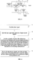
FIG. 1 is a schematic structural diagram of a sound restoration system according to an exemplary embodiment of the present invention; -
FIG. 2 is a schematic structural diagram of an optical fiber Michelson interference mechanism according to an exemplary embodiment of the present invention; -
FIG. 3 is a schematic structural diagram of an audio output mechanism according to an exemplary embodiment of the present invention; and -
FIG. 4 is a schematic flowchart of a sound restoration method according to an exemplary embodiment of the present invention. - Reference numerals and denotations thereof:
- 11 -laser generation mechanism
- 12 -beam splitting mechanism
- 13 -optical fiber Michelson interference mechanism
- 131 -sensing optical fiber
- 132 -front-end device
- 133 -rear-end device
- 134 -photodetector
- 14 -audio output mechanism
- 141 -processing unit
- 142 -control unit
- 143 -gating unit
- 144 -demodulation unit
- Exemplary embodiments of the present disclosure are hereinafter described more fully with reference to the accompany drawings. However, the exemplary embodiments may be implemented in a plurality of manners, and shall not be construed as being limited to the implementations described hereinafter. On the contrary, such exemplary embodiments more thoroughly and completely illustrate the present disclosure, and convey the concepts of the exemplary embodiments to persons skilled in the art. In the drawings, like reference numerals denote like or similar structures or elements. Therefore, detailed descriptions of these structures or elements are not given any further.
- In addition, the described characteristics, structures, or features may be incorporated in one or more embodiments in any suitable manner. In the description hereinafter, more details are provided such that sufficient understanding of the embodiments of the present disclosure may be achieved. However, a person skilled in the art would be aware that the technical solutions of the present disclosure may be practiced without one or more of the specific details, or may be practiced using other components, steps or the like. Under other circumstances, commonly known structures are not illustrated or described in detail to avoid various aspects of the present disclosure from becoming ambiguous.
- To facilitate a user of a distributed optical fiber perimeter security system to further make an accurate judgment on whether an abnormal event such as an intrusion behavior occurs, this exemplary embodiment firstly provides a sound restoration system. The sound restoration system is applied to the distributed optical fiber perimeter security system which monitors a plurality of protection areas. Referring to
FIG. 1 , in this exemplary embodiment, the distributed optical fiber perimeter security system is capable of monitoring eight protection areas, and the sound restoration system may mainly include alaser generation mechanism 11, abeam splitting mechanism 12, a plurality of optical fiberMichelson interference mechanisms 13, and anaudio output mechanism 14. In addition, a person skilled in the art would also configure other structures such as a power supply, a control component, a signal optimization component and the like according to actual needs. - The
laser generation mechanism 11 is mainly configured to provide a laser signal. For example, in this exemplary embodiment, to ensure high stability of light source frequency, high stability of light amplitude and monochromaticity, thelaser generation mechanism 11 is preferably a semiconductor distributed feedback laser (DFB) light source, thereby to improve ambient interference resistance capability of the system and improve signal-to-noise ratio of the entire system. Thebeam splitting mechanism 12 is mainly configured to split the laser signal into a plurality of input optical signal, and thus correspondingly provide the optical signals to the optical fiberMichelson interference mechanisms 13. Thebeam splitting mechanism 12 may be a beam splitter known in the prior art. In addition, other optical elements such as an isolator, a circulator and the like may be configured, which are not specifically limited in this exemplary embodiment. - The optical fiber Michelson interference mechanism is mainly configured to receive an input optical signal, and under effect of a sound pressure generated by a surrounding audio signal, output an interference signal carrying sound pressure information generated by the audio signal. In addition, the optical fiber
Michelson interference mechanism 13 has the advantages of high use security and reliability, strong interference resistance capability and long transmission distance, and thus is very applicable to the sound restoration system in this exemplary embodiment. In this exemplary embodiment, according to the number of protection areas, thebeam splitting mechanism 12 splits the laser signal into eight input optical signals, and totally eight optical fiberMichelson interference mechanisms 13 are configured. Each optical fiberMichelson interference mechanism 13 corresponds to and is arranged at one of the protection areas, such that the interference signal carrying sound pressure information generated by the audio signal of the corresponding protection area is acquired. - The
audio output mechanism 14 is mainly configured to receive the interference signals, and when an alarm signal of any of the protection areas is received, output an audio signal restored based on the interference signal of the protection area. For example, theaudio output mechanism 14 is mainly configured to receive the eight interference signals, output an audio signal restored based on the interference signal of aprotection area 2 upon receiving an alarm signal of theprotection area 2, and output an audio signal restored based on the interference signal of a protection area 7 upon receiving an alarm signal of the protection area 7, and the like. - In the sound restoration system, interference signals generated based on the sound pressures of audio signals of a plurality of protection areas are acquired, and when an alarm signal of any of the protection areas is received, an audio signal restored based on the interference signal of the protection area is output. In this way, a user is facilitated to further make an accurate judgment on whether an abnormal event such as an intrusion behavior occurs, thereby greatly improving the user's capability in identifying abnormal events, and thus timely knowing abnormal conditions and abnormal situations, and reducing false alarms. In addition, the sound restoration system outputs the corresponding audio signal only when the alarm signal is received, which in one aspect prevents interference caused to user's judgment and in another aspect saves system resources.
- Referring to
FIG. 2 , in this exemplary embodiment, the optical fiberMichelson interference mechanism 13 may include a sensingoptical fiber 131, a front-end device 132, a rear-end device 133 and anphotodetector 134. The sensingoptical fiber 131 has a reference arm and a sensing arm. The front-end device 132 is configured to receive the input optical signal, and transmit the input optical signal from a first end of the sensingoptical fiber 131 to the reference arm and the sensing arm. The rear-end device 133 is configured to feed back the input optical signal from a second end of the sensingoptical fiber 131 to the first end of the sensingoptical fiber 131 so as to form an interference signal. Thephotodetector 134 is arranged at the first end of the sensingoptical fiber 131, and configured to receive the interference signal, and output it after a photoelectric conversion. - For example, in this exemplary embodiment, the front-
end device 132 may include an optical fiber coupler, and the rear-end device 133 may include a Faraday rotator mirror (FRM) or a reflective mirror. The optical fiber coupler is configured to receive an input beam, and uniformly couple the input beam to the reference arm and the sensing arm of the sensingoptical fiber 131. The input beam in the reference arm and the sensing arm, after reaching a second end of the sensingoptical fiber 131, is reflected by the reflective mirror or the Faraday rotator mirror arranged at the second end of the sensingoptical fiber 131 back to the reference arm and the sensing arm of the sensingoptical fiber 131, to respectively form a reference light and a signal light. The reference light and the signal light form an interference signal in the optical fiber coupler, the interference signal is received by thephotodetector 134, and is output to theaudio output mechanism 14 after being photoelectrically converted. - In the optical fiber
Michelson interference mechanism 13, the sensingoptical fiber 131 may partially or totally multiplex the original transmission optical fiber of the distributed optical fiber perimeter security system, for example, the transmission optical fiber originally configured to sense and transmit intrusion vibration signals. In this way, there is no need to newly provide the sensingoptical fiber 131, or may prevent extra sensingoptical fibers 131, and thus to lower implementation cost of the system. In addition, the sensingoptical fiber 131 may be arranged in a mesh shape or a spiral shape. In this way, in one aspect, the interference signals may be more uniformly acquired, and in another aspect, a longer sensingoptical fiber 131 improves sensing sensitivity of the system. In addition, the rear-end device 133 is preferably a Faraday rotator mirror, for example, a 45-degree Faraday rotator mirror configured at a tail end of the reference arm and the sensing arm. In this way, the optical signals of the reference arm and the sensing arm rotate by 90 degrees after propagating back and forth, and thus impacts caused by random variations in a polarization state on the intensity of the interference signal are eliminated. - Based on the optical fiber
Michelson interference mechanism 13, in this exemplary embodiment, theaudio output mechanism 14 may restore the audio signal based on the light intensity of the interference signal. For example: - The light intensity of the interference signal output by the optical fiber
Michelson interference mechanism 13 is as follows:
where I 1 and I 2 respectively represent light intensities of the optical signals in the reference arm and the sensing arm and Δϕ represents a phase difference therebetween. According to the optical fiber strain theory, the impacts caused by temperature variations on the optical fiber are ignored, and the phase difference is as follows:
where n represents an effective refractive index of the sensingoptical fiber 131, λ represents an incident wavelength of the input optical signal, P 12 and P 11 represent Pockel constants, v represents a Poisson's ratio, ε 3 represents an axial length variation rate of the sensing arm, ε 3 = ΔL/L, L represents a vibration length, and ΔL represents an axial deformation. - According to the acoustic vibration theory, it may be considered that in a sound filed, the axial length variation rate ε 3 of the sensing arm of the sensing
optical fiber 131 is approximately proportional to the sound pressure as follows:
where k represents an inherent parameter of the sensingoptical fiber 131, and p represents a sound pressure when the sound signal is applied to the sensing arm. - As seen from the above formulae (1), (2) and (3), the light intensity of the interference signal output by the optical fiber
Michelson interference mechanism 13 is proportional to the ambient sound pressure. Therefore, the audio signals at site may be directly restored based on the interference signal output by the optical fiberMichelson interference mechanism 13. - As illustrated in
FIG. 3 , in this exemplary embodiment, theaudio output mechanism 14 may include aprocessing unit 141, acontrol unit 142 and agating unit 143. Theprocessing unit 141 is configured to restore an audio signal of any of the protection areas based on the interference signal of the protection area. Thecontrol unit 142 is configured to output a control signal upon receiving an alarm signal from any of the protection areas, wherein the control signal at least includes information of the protection area from which the alarm signal is sent. Thegating unit 143 is connected to thecontrol unit 142 and theprocessing unit 141, and configured to output, upon receiving the control signal and based on the control signal, the audio signal of the protection area from which the alarm signal is sent. In addition, in this exemplary embodiment, theaudio output mechanism 14 may further include ademodulation unit 144. Thedemodulation unit 144 is configured to demodulate the audio signal to play and store a sound corresponding to the audio signal. Nevertheless, persons skilled in the art may easily understand that, in other exemplary embodiments of the present disclosure, theprocessing unit 141 may start to restore the audio signal of a protection area from the interference signal of the protection area after receiving an alarm signal of the protection area, and then output the audio signal to thecontrol unit 142, which is not limited by the implementation in this exemplary embodiment. - For example, in this exemplary embodiment, the
processing unit 141 may be a signal processing circuit, thegating unit 143 may be a single-chip microcomputer gating circuit, and thecontrol unit 142 may be an industrial computer. The interference signals of eight protection areas enter a signal processing circuit after being photoelectrically converted by thephotodetector 134, and after the interference signals are processed, such as being filtered and regulated, via the signal processing circuit, the audio signals are demodulated, and eight audio signals are output to the single-chip microcomputer gating circuit. Upon receiving an alarm signal sent from any of the protection areas (the alarm signal may also be generated by the industrial computer itself), the industrial computer sends a control signal at least including information of the protection area to the single-chip microcomputer gating circuit, whereupon the single-chip microcomputer gating circuit gates the audio signal of the protection area and then output the audio signal to the industrial computer. Thedemodulation unit 144 may be demodulation software installed on the industrial computer. After the audio signal of the protection area is input into the industrial computer, the audio signal is demodulated via the demodulation software to play and store the corresponding sound. In addition, the user may set such parameters as play time, storage time and the like of the sound via the demodulation software. - In the audio output mechanism as described above, the processing unit, gating unit and control unit are illustrated by using specific hardware as an example, but they may also be implemented by using software or hardware in other types; likewise, the demodulation unit may also be implemented in other manners such as hardware; in addition, any combination of the processing unit, gating unit, control unit and demodulation unit may be integrated into a function module or component, which is not specifically limited in this exemplary embodiment.
- This exemplary embodiment further provides a distributed optical fiber perimeter security system. The distributed optical fiber perimeter security system mainly includes an intrusion sensing system and any of the sound restoration system as described above. In addition, the security system may further include an alarming unit and other components. The intrusion sensing system is configured to acquire intrusion vibration signals of a plurality of protection areas. As such, the alarming unit judges, based on the intrusion vibration signals, whether an abnormal event such as an intrusion behavior occurs in the protection areas. The alarming unit may be the above mentioned industrial computer, and when sensing that an abnormal event occurs in a certain protection area, the alarming unit may send an alarm signal of the protection area. The sound restoration system as defined above outputs an audio signal restored based on an interference signal of the protection area when the alarm signal of the protection area is received. Therefore, by using the distributed optical fiber perimeter security system in this exemplary embodiment, when an intrusion event occurs in any of the protection areas, the user may correspondingly hear the real-time sound of the protection area on site. Besides, since restoration of the audio signal is accurate, the user may further judge and determine the situation on site.
- Furthermore, this exemplary embodiment further provides a sound restoration method corresponding to any of the above sound restoration systems. As illustrated in
FIG. 4 , the sound restoration method may include: - step S1: providing a laser signal;
- step S2: splitting the laser signal into a plurality of input optical signals;
- step S3: providing a plurality of optical fiber Michelson interference mechanisms and correspondingly arranging the optical fiber Michelson interference mechanisms in the protection areas, each of the optical fiber Michelson interference mechanisms being configured to receive one of the input optical signals and output an interference signal in response to a surrounding sound pressure; and
- step S4: receiving the interference signal, and when an alarm signal of any of the protection areas is received, outputting an audio signal restored based on the interference signal of the protection area.
- Implementations and more details of the distributed optical fiber perimeter security systems and the sound restoration methods in this exemplary embodiment have been described in detail in the above descriptions of the sound restoration systems, which are thus not described herein any further.
- In conclusion, in this exemplary embodiment, interference signals generated based on the sound pressures of audio signals of a plurality of protection areas are acquired, and when an alarm signal of any of the protection areas is received, an audio signal restored based on the interference signal of the protection area is output. In this way, a user is facilitated to further make an accurate judgment on whether an abnormal event such as an intrusion behavior occurs, thereby greatly improving the user's capability in identifying abnormal events, and thus timely knowing abnormal conditions and abnormal situations, and reducing false alarms. In addition, the sound restoration system outputs the corresponding audio signal only when the alarm signal is received, which in one aspect prevents interference caused to user's judgment and in another aspect saves system resources. Further, in this exemplary embodiment, by establishing an optical fiber Michelson interference mechanism and providing an interference signal restoration algorithm, accuracy of restoring audio signals may be improved, and the user is facilitated to make a more accurate judgment. In addition, in this exemplary embodiment, the sensing optical fiber in the optical fiber Michelson interference mechanism may multiplex the original optical fiber in the distributed optical fiber perimeter security system. Therefore, the implementation cost is effectively reduced, and a high practicality is achieved.
- The present disclosure has been described with reference to the above embodiments. However, the above embodiments are merely exemplary embodiments for practicing the present disclosure. It should be noted that the disclosed embodiments are not intended to limit the scope of the present disclosure. On the contrary, various modifications and variations made without departing from the spirit and scope of the present disclosure shall fall within the protection scope of the present disclosure.
Claims (15)
- A sound restoration system, applied to a distributed optical fiber perimeter security system which monitors several protection areas, the sound restoration system comprising:a laser generation mechanism, configured to provide a laser signal;a beam splitting mechanism, configured to split the laser signal into a plurality of input optical signals;a plurality of optical fiber Michelson interference mechanisms, correspondingly arranged in the protection areas, each of the optical fiber Michelson interference mechanisms being configured to receive one of the input optical signals and output an interference signal in response to a surrounding sound pressure; andan audio output mechanism, configured to receive the interference signals, and when an alarm signal of any of the protection areas is received, output an audio signal restored based on the interference signal of the protection area.
- The sound restoration system according to claim 1, wherein the audio output mechanism is configured to restore the audio signal based on a light intensity of the interference signal.
- The sound restoration system according to claim 1, wherein the optical fiber Michelson interference mechanism comprises:a sensing optical fiber, having a reference arm and a sensing arm;a front-end device, configured to receive the input optical signal, and transmit the input optical signal from a first end of the sensing optical fiber to the reference arm and the sensing arm;a rear-end device, configured to feed back the input optical signal from a second end of the sensing optical fiber to the first end of the sensing optical fiber so as to form an interference signal; anda photodetector, arranged at the first end of the sensing optical fiber, and configured to receive and output the interference signal.
- The sound restoration system according to claim 3, wherein the audio output mechanism is configured to restore the audio signal based on the following equations:


- The sound restoration system according to claim 3, wherein the front-end device comprises an optical fiber coupler.
- The sound restoration system according to claim 3, wherein the rear-end device comprises a Faraday rotator mirror or a reflective mirror.
- The sound restoration system according to claim 3, wherein the sensing optical fiber is configured to at least partially multiplex an intrusion-sensing optical fiber in the distributed optical fiber perimeter security system.
- The sound restoration system according to claim 3, wherein the sensing optical fiber is arranged in a mesh shape, a spiral shape or a straight line shape.
- The sound restoration system according to any one of claims 1 to 8, wherein the audio output mechanism comprises:a processing unit, configured to restore, based on the interference signal of any of the protection areas, an audio signal of the protection area;a control unit, configured to output a control signal upon receiving an alarm signal of any of the protection areas, the control signal at least comprising information of the protection area from which the alarm signal is sent; anda gating unit, connected to the control unit and the processing unit, and configured to output, upon receiving the control signal and based on the control signal, the audio signal of the protection area from which the alarm signal is sent.
- The sound restoration system according to claim 9, wherein the audio output mechanism further comprises:
a demodulation unit, configured to demodulate the audio signal to play and/or store a sound corresponding to the audio signal. - A distributed optical fiber perimeter security system, comprising:an intrusion sensing system, configured to acquire intrusion vibration signals of a plurality of protection areas;an alarming unit, configured to send, when judging that an abnormal event occurs in any of the protection areas based on the intrusion vibration signals, an alarm signal of the protection area; anda sound restoration system as defined in any one of claims 1 to 10, configured to output an audio signal restored based on an interference signal of the protection area when the alarm signal of the protection area is received.
- The distributed optical fiber perimeter security system according to claim 11, wherein the intrusion sensing system comprises an optical fiber configured to sense and transmit the intrusion vibration signals, a sensing optical fiber of the optical fiber Michelson interference mechanism at least partially multiplexing the optical fiber.
- A sound restoration method, applied to a distributed optical fiber perimeter security system which monitors several protection areas, the sound restoration method comprising:providing a laser signal;splitting the laser signal into a plurality of input optical signals;providing a plurality of optical fiber Michelson interference mechanisms and correspondingly arranging the optical fiber Michelson interference mechanisms in the protection areas, each of the optical fiber Michelson interference mechanisms being configured to receive one of the input optical signals and output an interference signal in response to a surrounding sound pressure; andreceiving the interference signals, and when an alarm signal of any of the protection areas is received, outputting an audio signal restored based on the interference signal of the protection area.
- The sound restoration method according to claim 13, wherein the audio signal is restored based on a light intensity of the interference signal.
- The sound restoration method according to claim 13, wherein the audio signal is restored based on the following equations:


Applications Claiming Priority (2)
| Application Number | Priority Date | Filing Date | Title |
|---|---|---|---|
| CN201510557454.3A CN105096490B (en) | 2015-09-02 | 2015-09-02 | Distributed optical fiber perimeter security system, sound restoration system and method |
| PCT/CN2016/095649 WO2017036304A1 (en) | 2015-09-02 | 2016-08-17 | Distributed optical fiber perimeter security system, and sound restoration system and method |
Publications (3)
| Publication Number | Publication Date |
|---|---|
| EP3321901A1 true EP3321901A1 (en) | 2018-05-16 |
| EP3321901A4 EP3321901A4 (en) | 2019-02-27 |
| EP3321901B1 EP3321901B1 (en) | 2020-03-25 |
Family
ID=54576813
Family Applications (1)
| Application Number | Title | Priority Date | Filing Date |
|---|---|---|---|
| EP16840733.6A Active EP3321901B1 (en) | 2015-09-02 | 2016-08-17 | Distributed optical fiber perimeter security system, and sound restoration system and method |
Country Status (6)
| Country | Link |
|---|---|
| EP (1) | EP3321901B1 (en) |
| CN (1) | CN105096490B (en) |
| BR (1) | BR112017024077B1 (en) |
| EA (1) | EA036635B1 (en) |
| MX (1) | MX2017015391A (en) |
| WO (1) | WO2017036304A1 (en) |
Cited By (4)
| Publication number | Priority date | Publication date | Assignee | Title |
|---|---|---|---|---|
| CN109272688A (en) * | 2018-09-25 | 2019-01-25 | 武汉理工光科股份有限公司 | The tactful automatic adjusting method of fiber grating perimeter security system alarm and system |
| CN109523729A (en) * | 2018-10-31 | 2019-03-26 | 天津大学 | Based on the optical fiber perimeter security protection intrusion event recognition methods modeled entirely and identifier |
| CN112556824A (en) * | 2020-12-22 | 2021-03-26 | 北京航天控制仪器研究所 | Ultra-high sound pressure noise test optical fiber microphone system for engine |
| US20210156734A1 (en) * | 2019-11-21 | 2021-05-27 | Baker Hughes Oilfield Operations Llc | Drift correction in a fiber optic distributed acoustic sensing system |
Families Citing this family (12)
| Publication number | Priority date | Publication date | Assignee | Title |
|---|---|---|---|---|
| CN105096490B (en) * | 2015-09-02 | 2020-12-25 | 同方威视技术股份有限公司 | Distributed optical fiber perimeter security system, sound restoration system and method |
| CN105551163B (en) * | 2016-02-29 | 2018-05-08 | 刘海 | A kind of optical-fiber intelligent anti-theft device |
| CN105931402B (en) * | 2016-06-27 | 2018-06-05 | 上海波汇科技股份有限公司 | Optical fiber perimeter intrusion detection method based on image identification |
| CA3043239A1 (en) | 2016-11-10 | 2018-05-17 | Mark Andrew Englund | Acoustic method and system for providing digital data |
| CN108426630B (en) * | 2017-12-14 | 2020-11-10 | 北京遥测技术研究所 | double-Michelson interference type sound measurement sensor |
| CN109360359A (en) * | 2018-11-22 | 2019-02-19 | 桂林聚联科技有限公司 | A kind of device and method of ancillary vibration fence weatherproof |
| JP7211134B2 (en) * | 2019-02-12 | 2023-01-24 | 日本電信電話株式会社 | Aerial optical fiber cable inspection method, aerial optical fiber cable inspection device and program |
| CN109974836A (en) * | 2019-04-09 | 2019-07-05 | 苏州珈全智能科技有限公司 | A kind of device and method improving φ-OTDR frequency response |
| CN111341049B (en) * | 2020-03-31 | 2021-04-20 | 华中科技大学 | Tunnel foreign matter invasion identification and positioning method and device |
| CN112578190B (en) * | 2020-11-25 | 2023-03-14 | 中国科学院上海光学精密机械研究所 | FAST distributed optical fiber universe monitoring system |
| CN113507316B (en) * | 2021-06-22 | 2023-04-18 | 武汉凹伟能源科技有限公司 | Single-fiber bidirectional passive optical fiber audio transmission system and optical fiber transmission network |
| TWI820724B (en) * | 2022-05-24 | 2023-11-01 | 中華電信股份有限公司 | Optical fiber perimeter intrusion detection system and intrusion detection method |
Family Cites Families (17)
| Publication number | Priority date | Publication date | Assignee | Title |
|---|---|---|---|---|
| AU747525B2 (en) * | 1998-12-18 | 2002-05-16 | Future Fibre Technologies Pty Ltd | Apparatus and method for monitoring a structure using a counter-propagating signal method for locating events |
| WO2003014774A2 (en) * | 2001-08-10 | 2003-02-20 | The Board Of Trustees Of The Leland Stanford Junior University | Amplified tree structure technology for fiber optic sensor arrays |
| CA2467898A1 (en) * | 2004-05-21 | 2005-11-21 | Pure Technologies Ltd. | Fiber optic sensor method and apparatus |
| JP2008139170A (en) * | 2006-12-01 | 2008-06-19 | Fuji Heavy Ind Ltd | System for detecting impact |
| GB2445364B (en) * | 2006-12-29 | 2010-02-17 | Schlumberger Holdings | Fault-tolerant distributed fiber optic intrusion detection |
| CN101452626A (en) * | 2007-11-30 | 2009-06-10 | 石家庄紫藤惠尔科技有限公司 | On-site monitoring wireless burglar alarm |
| CN201191221Y (en) * | 2008-05-09 | 2009-02-04 | 东南大学 | Disturbance signal determination module of distributed optical fiber vibration sensor system |
| CN101901531B (en) * | 2009-05-31 | 2012-12-12 | 中国石油天然气管道局 | Fiber interferometer-based area anti-intrusion method |
| CN101608946B (en) * | 2009-06-23 | 2011-05-25 | 中国人民解放军海军工程大学 | Fiber laser hydrophone signal demodulating system |
| JP2011214921A (en) * | 2010-03-31 | 2011-10-27 | Oki Electric Industry Co Ltd | Interference type optical fiber sensor system and calculator |
| CA2813869C (en) * | 2010-10-14 | 2016-05-17 | Fiber Sensys, Inc. | Interferometer systems |
| CN101969344B (en) * | 2010-10-15 | 2014-01-08 | 复旦大学 | Fiber photoelastic effect based larger-area sound monitoring system |
| CA2780396A1 (en) * | 2012-06-13 | 2013-12-13 | Robert Keith Harman | Fiber optic interferometric perimeter security apparatus and method |
| CN103208161B (en) * | 2013-03-19 | 2016-02-03 | 石家庄供电公司 | Active detection type fiber grating cable tunnel safety defense monitoring system |
| CN103595489B (en) * | 2013-11-08 | 2015-08-26 | 苏州桑泰海洋仪器研发有限责任公司 | A kind of intercom system under water based on optical fiber sensing technology |
| CN105096490B (en) * | 2015-09-02 | 2020-12-25 | 同方威视技术股份有限公司 | Distributed optical fiber perimeter security system, sound restoration system and method |
| CN205003805U (en) * | 2015-09-02 | 2016-01-27 | 同方威视技术股份有限公司 | Distributed optical fiber perimeter security protection system and sound reduction system |
-
2015
- 2015-09-02 CN CN201510557454.3A patent/CN105096490B/en active Active
-
2016
- 2016-08-17 EP EP16840733.6A patent/EP3321901B1/en active Active
- 2016-08-17 MX MX2017015391A patent/MX2017015391A/en active IP Right Grant
- 2016-08-17 EA EA201792295A patent/EA036635B1/en not_active IP Right Cessation
- 2016-08-17 WO PCT/CN2016/095649 patent/WO2017036304A1/en active Application Filing
- 2016-08-17 BR BR112017024077-7A patent/BR112017024077B1/en active IP Right Grant
Cited By (5)
| Publication number | Priority date | Publication date | Assignee | Title |
|---|---|---|---|---|
| CN109272688A (en) * | 2018-09-25 | 2019-01-25 | 武汉理工光科股份有限公司 | The tactful automatic adjusting method of fiber grating perimeter security system alarm and system |
| CN109523729A (en) * | 2018-10-31 | 2019-03-26 | 天津大学 | Based on the optical fiber perimeter security protection intrusion event recognition methods modeled entirely and identifier |
| US20210156734A1 (en) * | 2019-11-21 | 2021-05-27 | Baker Hughes Oilfield Operations Llc | Drift correction in a fiber optic distributed acoustic sensing system |
| US11796382B2 (en) * | 2019-11-21 | 2023-10-24 | Baker Hughes Oilfield Operations Llc | Drift correction in a fiber optic distributed acoustic sensing system |
| CN112556824A (en) * | 2020-12-22 | 2021-03-26 | 北京航天控制仪器研究所 | Ultra-high sound pressure noise test optical fiber microphone system for engine |
Also Published As
| Publication number | Publication date |
|---|---|
| BR112017024077B1 (en) | 2022-08-23 |
| EP3321901A4 (en) | 2019-02-27 |
| MX2017015391A (en) | 2018-03-01 |
| WO2017036304A1 (en) | 2017-03-09 |
| CN105096490B (en) | 2020-12-25 |
| EP3321901B1 (en) | 2020-03-25 |
| CN105096490A (en) | 2015-11-25 |
| EA201792295A1 (en) | 2018-04-30 |
| BR112017024077A2 (en) | 2018-07-24 |
| EA036635B1 (en) | 2020-12-02 |
Similar Documents
| Publication | Publication Date | Title |
|---|---|---|
| EP3321901B1 (en) | Distributed optical fiber perimeter security system, and sound restoration system and method | |
| AU760272B2 (en) | Intrinsic securing of fibre optic communication links | |
| US8947232B2 (en) | Fault-tolerant distributed fiber optic intrusion detection | |
| CN100561144C (en) | Distributed optical fiber vibration sensing method and device | |
| CN110031082B (en) | Event positioning method, device and application of distributed optical fiber vibration monitoring system | |
| CN104977233B (en) | Hydraulic structures and basic seepage flow situation distribution type fiber-optic identification system thereof and method | |
| US11248952B2 (en) | Fiber distributed acoustic sensing system | |
| US7514670B2 (en) | Distributed fiber optic sensor with location capability | |
| Linze et al. | Development of an intrusion sensor based on a polarization-OTDR system | |
| CN103208161A (en) | Active detecting type fiber grating cable tunnel security and protection monitoring system | |
| CN103542925A (en) | Quasi-distributed optical vibrating sensing device | |
| JP2019039881A (en) | Vibration detection optical fiber sensor and method for detecting vibration | |
| CN204789261U (en) | Hydro -structure thing and basis seepage flow situation distributed optical fiber identification system thereof | |
| Dang et al. | Simultaneous distributed vibration and temperature sensing using multicore fiber | |
| IL146075A (en) | Intrinsic securing of fibre optic communication links | |
| JP2013185922A (en) | Optical fiber vibration sensor | |
| CN205003805U (en) | Distributed optical fiber perimeter security protection system and sound reduction system | |
| CN111510209B (en) | Optical fiber vibration monitoring method and device | |
| EP2144207A1 (en) | Optical fiber anti-intrusion system | |
| Kipnoo et al. | All optical polarization-based and DSP-Assisted distributed fiber sensor for earth mass movements caused by environmental factors | |
| Kumagai et al. | Fiber-optic intrusion detection sensor for physical security system | |
| Zyczkowski et al. | Simple fiber optic sensor for applications in security systems | |
| Palchun et al. | Monitoring and methods of early diagnostics of damage to optical fibers | |
| KR100213800B1 (en) | Guard system using light fiber | |
| Szustakowski et al. | Fiber optic sensors for perimeter security with intruder localisation |
Legal Events
| Date | Code | Title | Description |
|---|---|---|---|
| STAA | Information on the status of an ep patent application or granted ep patent |
Free format text: STATUS: THE INTERNATIONAL PUBLICATION HAS BEEN MADE |
|
| PUAI | Public reference made under article 153(3) epc to a published international application that has entered the european phase |
Free format text: ORIGINAL CODE: 0009012 |
|
| STAA | Information on the status of an ep patent application or granted ep patent |
Free format text: STATUS: REQUEST FOR EXAMINATION WAS MADE |
|
| 17P | Request for examination filed |
Effective date: 20171107 |
|
| AK | Designated contracting states |
Kind code of ref document: A1 Designated state(s): AL AT BE BG CH CY CZ DE DK EE ES FI FR GB GR HR HU IE IS IT LI LT LU LV MC MK MT NL NO PL PT RO RS SE SI SK SM TR |
|
| AX | Request for extension of the european patent |
Extension state: BA ME |
|
| DAV | Request for validation of the european patent (deleted) | ||
| DAX | Request for extension of the european patent (deleted) | ||
| A4 | Supplementary search report drawn up and despatched |
Effective date: 20190129 |
|
| RIC1 | Information provided on ipc code assigned before grant |
Ipc: G08B 13/186 20060101ALI20190123BHEP Ipc: G01H 9/00 20060101ALI20190123BHEP Ipc: G08B 13/00 20060101AFI20190123BHEP Ipc: G08B 13/12 20060101ALI20190123BHEP Ipc: G08B 13/16 20060101ALI20190123BHEP |
|
| GRAP | Despatch of communication of intention to grant a patent |
Free format text: ORIGINAL CODE: EPIDOSNIGR1 |
|
| STAA | Information on the status of an ep patent application or granted ep patent |
Free format text: STATUS: GRANT OF PATENT IS INTENDED |
|
| INTG | Intention to grant announced |
Effective date: 20191010 |
|
| GRAS | Grant fee paid |
Free format text: ORIGINAL CODE: EPIDOSNIGR3 |
|
| GRAA | (expected) grant |
Free format text: ORIGINAL CODE: 0009210 |
|
| STAA | Information on the status of an ep patent application or granted ep patent |
Free format text: STATUS: THE PATENT HAS BEEN GRANTED |
|
| AK | Designated contracting states |
Kind code of ref document: B1 Designated state(s): AL AT BE BG CH CY CZ DE DK EE ES FI FR GB GR HR HU IE IS IT LI LT LU LV MC MK MT NL NO PL PT RO RS SE SI SK SM TR |
|
| REG | Reference to a national code |
Ref country code: GB Ref legal event code: FG4D |
|
| REG | Reference to a national code |
Ref country code: DE Ref legal event code: R096 Ref document number: 602016032724 Country of ref document: DE |
|
| REG | Reference to a national code |
Ref country code: AT Ref legal event code: REF Ref document number: 1249460 Country of ref document: AT Kind code of ref document: T Effective date: 20200415 Ref country code: IE Ref legal event code: FG4D |
|
| PG25 | Lapsed in a contracting state [announced via postgrant information from national office to epo] |
Ref country code: FI Free format text: LAPSE BECAUSE OF FAILURE TO SUBMIT A TRANSLATION OF THE DESCRIPTION OR TO PAY THE FEE WITHIN THE PRESCRIBED TIME-LIMIT Effective date: 20200325 Ref country code: NO Free format text: LAPSE BECAUSE OF FAILURE TO SUBMIT A TRANSLATION OF THE DESCRIPTION OR TO PAY THE FEE WITHIN THE PRESCRIBED TIME-LIMIT Effective date: 20200625 Ref country code: RS Free format text: LAPSE BECAUSE OF FAILURE TO SUBMIT A TRANSLATION OF THE DESCRIPTION OR TO PAY THE FEE WITHIN THE PRESCRIBED TIME-LIMIT Effective date: 20200325 |
|
| PG25 | Lapsed in a contracting state [announced via postgrant information from national office to epo] |
Ref country code: BG Free format text: LAPSE BECAUSE OF FAILURE TO SUBMIT A TRANSLATION OF THE DESCRIPTION OR TO PAY THE FEE WITHIN THE PRESCRIBED TIME-LIMIT Effective date: 20200625 Ref country code: GR Free format text: LAPSE BECAUSE OF FAILURE TO SUBMIT A TRANSLATION OF THE DESCRIPTION OR TO PAY THE FEE WITHIN THE PRESCRIBED TIME-LIMIT Effective date: 20200626 Ref country code: LV Free format text: LAPSE BECAUSE OF FAILURE TO SUBMIT A TRANSLATION OF THE DESCRIPTION OR TO PAY THE FEE WITHIN THE PRESCRIBED TIME-LIMIT Effective date: 20200325 Ref country code: SE Free format text: LAPSE BECAUSE OF FAILURE TO SUBMIT A TRANSLATION OF THE DESCRIPTION OR TO PAY THE FEE WITHIN THE PRESCRIBED TIME-LIMIT Effective date: 20200325 Ref country code: HR Free format text: LAPSE BECAUSE OF FAILURE TO SUBMIT A TRANSLATION OF THE DESCRIPTION OR TO PAY THE FEE WITHIN THE PRESCRIBED TIME-LIMIT Effective date: 20200325 |
|
| REG | Reference to a national code |
Ref country code: NL Ref legal event code: MP Effective date: 20200325 |
|
| REG | Reference to a national code |
Ref country code: LT Ref legal event code: MG4D |
|
| PG25 | Lapsed in a contracting state [announced via postgrant information from national office to epo] |
Ref country code: NL Free format text: LAPSE BECAUSE OF FAILURE TO SUBMIT A TRANSLATION OF THE DESCRIPTION OR TO PAY THE FEE WITHIN THE PRESCRIBED TIME-LIMIT Effective date: 20200325 |
|
| PG25 | Lapsed in a contracting state [announced via postgrant information from national office to epo] |
Ref country code: PT Free format text: LAPSE BECAUSE OF FAILURE TO SUBMIT A TRANSLATION OF THE DESCRIPTION OR TO PAY THE FEE WITHIN THE PRESCRIBED TIME-LIMIT Effective date: 20200818 Ref country code: LT Free format text: LAPSE BECAUSE OF FAILURE TO SUBMIT A TRANSLATION OF THE DESCRIPTION OR TO PAY THE FEE WITHIN THE PRESCRIBED TIME-LIMIT Effective date: 20200325 Ref country code: SK Free format text: LAPSE BECAUSE OF FAILURE TO SUBMIT A TRANSLATION OF THE DESCRIPTION OR TO PAY THE FEE WITHIN THE PRESCRIBED TIME-LIMIT Effective date: 20200325 Ref country code: CZ Free format text: LAPSE BECAUSE OF FAILURE TO SUBMIT A TRANSLATION OF THE DESCRIPTION OR TO PAY THE FEE WITHIN THE PRESCRIBED TIME-LIMIT Effective date: 20200325 Ref country code: IS Free format text: LAPSE BECAUSE OF FAILURE TO SUBMIT A TRANSLATION OF THE DESCRIPTION OR TO PAY THE FEE WITHIN THE PRESCRIBED TIME-LIMIT Effective date: 20200725 Ref country code: RO Free format text: LAPSE BECAUSE OF FAILURE TO SUBMIT A TRANSLATION OF THE DESCRIPTION OR TO PAY THE FEE WITHIN THE PRESCRIBED TIME-LIMIT Effective date: 20200325 Ref country code: SM Free format text: LAPSE BECAUSE OF FAILURE TO SUBMIT A TRANSLATION OF THE DESCRIPTION OR TO PAY THE FEE WITHIN THE PRESCRIBED TIME-LIMIT Effective date: 20200325 Ref country code: EE Free format text: LAPSE BECAUSE OF FAILURE TO SUBMIT A TRANSLATION OF THE DESCRIPTION OR TO PAY THE FEE WITHIN THE PRESCRIBED TIME-LIMIT Effective date: 20200325 |
|
| REG | Reference to a national code |
Ref country code: AT Ref legal event code: MK05 Ref document number: 1249460 Country of ref document: AT Kind code of ref document: T Effective date: 20200325 |
|
| REG | Reference to a national code |
Ref country code: DE Ref legal event code: R097 Ref document number: 602016032724 Country of ref document: DE |
|
| PG25 | Lapsed in a contracting state [announced via postgrant information from national office to epo] |
Ref country code: IT Free format text: LAPSE BECAUSE OF FAILURE TO SUBMIT A TRANSLATION OF THE DESCRIPTION OR TO PAY THE FEE WITHIN THE PRESCRIBED TIME-LIMIT Effective date: 20200325 Ref country code: DK Free format text: LAPSE BECAUSE OF FAILURE TO SUBMIT A TRANSLATION OF THE DESCRIPTION OR TO PAY THE FEE WITHIN THE PRESCRIBED TIME-LIMIT Effective date: 20200325 Ref country code: AT Free format text: LAPSE BECAUSE OF FAILURE TO SUBMIT A TRANSLATION OF THE DESCRIPTION OR TO PAY THE FEE WITHIN THE PRESCRIBED TIME-LIMIT Effective date: 20200325 Ref country code: ES Free format text: LAPSE BECAUSE OF FAILURE TO SUBMIT A TRANSLATION OF THE DESCRIPTION OR TO PAY THE FEE WITHIN THE PRESCRIBED TIME-LIMIT Effective date: 20200325 |
|
| PLBE | No opposition filed within time limit |
Free format text: ORIGINAL CODE: 0009261 |
|
| STAA | Information on the status of an ep patent application or granted ep patent |
Free format text: STATUS: NO OPPOSITION FILED WITHIN TIME LIMIT |
|
| PG25 | Lapsed in a contracting state [announced via postgrant information from national office to epo] |
Ref country code: PL Free format text: LAPSE BECAUSE OF FAILURE TO SUBMIT A TRANSLATION OF THE DESCRIPTION OR TO PAY THE FEE WITHIN THE PRESCRIBED TIME-LIMIT Effective date: 20200325 |
|
| REG | Reference to a national code |
Ref country code: DE Ref legal event code: R119 Ref document number: 602016032724 Country of ref document: DE |
|
| 26N | No opposition filed |
Effective date: 20210112 |
|
| PG25 | Lapsed in a contracting state [announced via postgrant information from national office to epo] |
Ref country code: MC Free format text: LAPSE BECAUSE OF FAILURE TO SUBMIT A TRANSLATION OF THE DESCRIPTION OR TO PAY THE FEE WITHIN THE PRESCRIBED TIME-LIMIT Effective date: 20200325 |
|
| REG | Reference to a national code |
Ref country code: CH Ref legal event code: PL |
|
| GBPC | Gb: european patent ceased through non-payment of renewal fee |
Effective date: 20200817 |
|
| PG25 | Lapsed in a contracting state [announced via postgrant information from national office to epo] |
Ref country code: CH Free format text: LAPSE BECAUSE OF NON-PAYMENT OF DUE FEES Effective date: 20200831 Ref country code: LU Free format text: LAPSE BECAUSE OF NON-PAYMENT OF DUE FEES Effective date: 20200817 Ref country code: LI Free format text: LAPSE BECAUSE OF NON-PAYMENT OF DUE FEES Effective date: 20200831 |
|
| REG | Reference to a national code |
Ref country code: BE Ref legal event code: MM Effective date: 20200831 |
|
| PG25 | Lapsed in a contracting state [announced via postgrant information from national office to epo] |
Ref country code: SI Free format text: LAPSE BECAUSE OF FAILURE TO SUBMIT A TRANSLATION OF THE DESCRIPTION OR TO PAY THE FEE WITHIN THE PRESCRIBED TIME-LIMIT Effective date: 20200325 |
|
| PG25 | Lapsed in a contracting state [announced via postgrant information from national office to epo] |
Ref country code: FR Free format text: LAPSE BECAUSE OF NON-PAYMENT OF DUE FEES Effective date: 20200831 Ref country code: DE Free format text: LAPSE BECAUSE OF NON-PAYMENT OF DUE FEES Effective date: 20210302 |
|
| PG25 | Lapsed in a contracting state [announced via postgrant information from national office to epo] |
Ref country code: BE Free format text: LAPSE BECAUSE OF NON-PAYMENT OF DUE FEES Effective date: 20200831 Ref country code: GB Free format text: LAPSE BECAUSE OF NON-PAYMENT OF DUE FEES Effective date: 20200817 Ref country code: IE Free format text: LAPSE BECAUSE OF NON-PAYMENT OF DUE FEES Effective date: 20200817 |
|
| PG25 | Lapsed in a contracting state [announced via postgrant information from national office to epo] |
Ref country code: TR Free format text: LAPSE BECAUSE OF FAILURE TO SUBMIT A TRANSLATION OF THE DESCRIPTION OR TO PAY THE FEE WITHIN THE PRESCRIBED TIME-LIMIT Effective date: 20200325 Ref country code: MT Free format text: LAPSE BECAUSE OF FAILURE TO SUBMIT A TRANSLATION OF THE DESCRIPTION OR TO PAY THE FEE WITHIN THE PRESCRIBED TIME-LIMIT Effective date: 20200325 Ref country code: CY Free format text: LAPSE BECAUSE OF FAILURE TO SUBMIT A TRANSLATION OF THE DESCRIPTION OR TO PAY THE FEE WITHIN THE PRESCRIBED TIME-LIMIT Effective date: 20200325 |
|
| PG25 | Lapsed in a contracting state [announced via postgrant information from national office to epo] |
Ref country code: MK Free format text: LAPSE BECAUSE OF FAILURE TO SUBMIT A TRANSLATION OF THE DESCRIPTION OR TO PAY THE FEE WITHIN THE PRESCRIBED TIME-LIMIT Effective date: 20200325 Ref country code: AL Free format text: LAPSE BECAUSE OF FAILURE TO SUBMIT A TRANSLATION OF THE DESCRIPTION OR TO PAY THE FEE WITHIN THE PRESCRIBED TIME-LIMIT Effective date: 20200325 |