EP3321758B1 - A method of controlling an electrical taxiing system - Google Patents
A method of controlling an electrical taxiing system Download PDFInfo
- Publication number
- EP3321758B1 EP3321758B1 EP17201267.6A EP17201267A EP3321758B1 EP 3321758 B1 EP3321758 B1 EP 3321758B1 EP 17201267 A EP17201267 A EP 17201267A EP 3321758 B1 EP3321758 B1 EP 3321758B1
- Authority
- EP
- European Patent Office
- Prior art keywords
- speed
- control method
- speed setpoint
- block
- aircraft
- Prior art date
- Legal status (The legal status is an assumption and is not a legal conclusion. Google has not performed a legal analysis and makes no representation as to the accuracy of the status listed.)
- Active
Links
- 238000000034 method Methods 0.000 title claims description 22
- 230000001133 acceleration Effects 0.000 claims description 25
- 230000004044 response Effects 0.000 claims description 10
- 230000001131 transforming effect Effects 0.000 claims description 3
- 230000033228 biological regulation Effects 0.000 description 9
- 238000005259 measurement Methods 0.000 description 7
- 238000001914 filtration Methods 0.000 description 6
- 230000001276 controlling effect Effects 0.000 description 5
- 230000033001 locomotion Effects 0.000 description 4
- 230000001105 regulatory effect Effects 0.000 description 4
- 238000004364 calculation method Methods 0.000 description 2
- 230000000694 effects Effects 0.000 description 2
- 230000010354 integration Effects 0.000 description 2
- 230000009257 reactivity Effects 0.000 description 2
- 230000035945 sensitivity Effects 0.000 description 2
- 230000003068 static effect Effects 0.000 description 2
- 230000009471 action Effects 0.000 description 1
- 230000008901 benefit Effects 0.000 description 1
- 230000005540 biological transmission Effects 0.000 description 1
- 230000001934 delay Effects 0.000 description 1
- 238000009795 derivation Methods 0.000 description 1
- 230000010355 oscillation Effects 0.000 description 1
- 230000001902 propagating effect Effects 0.000 description 1
- 230000006641 stabilisation Effects 0.000 description 1
- 238000011105 stabilization Methods 0.000 description 1
Images

Classifications
-
- G—PHYSICS
- G05—CONTROLLING; REGULATING
- G05D—SYSTEMS FOR CONTROLLING OR REGULATING NON-ELECTRIC VARIABLES
- G05D1/00—Control of position, course or altitude of land, water, air, or space vehicles, e.g. automatic pilot
- G05D1/0083—Control of position, course or altitude of land, water, air, or space vehicles, e.g. automatic pilot to help an aircraft pilot in the rolling phase
-
- B—PERFORMING OPERATIONS; TRANSPORTING
- B64—AIRCRAFT; AVIATION; COSMONAUTICS
- B64C—AEROPLANES; HELICOPTERS
- B64C25/00—Alighting gear
- B64C25/32—Alighting gear characterised by elements which contact the ground or similar surface
- B64C25/405—Powered wheels, e.g. for taxing
-
- G—PHYSICS
- G05—CONTROLLING; REGULATING
- G05B—CONTROL OR REGULATING SYSTEMS IN GENERAL; FUNCTIONAL ELEMENTS OF SUCH SYSTEMS; MONITORING OR TESTING ARRANGEMENTS FOR SUCH SYSTEMS OR ELEMENTS
- G05B11/00—Automatic controllers
- G05B11/01—Automatic controllers electric
- G05B11/36—Automatic controllers electric with provision for obtaining particular characteristics, e.g. proportional, integral, differential
- G05B11/42—Automatic controllers electric with provision for obtaining particular characteristics, e.g. proportional, integral, differential for obtaining a characteristic which is both proportional and time-dependent, e.g. P.I., P.I.D.
-
- B—PERFORMING OPERATIONS; TRANSPORTING
- B64—AIRCRAFT; AVIATION; COSMONAUTICS
- B64C—AEROPLANES; HELICOPTERS
- B64C25/00—Alighting gear
- B64C25/32—Alighting gear characterised by elements which contact the ground or similar surface
- B64C25/34—Alighting gear characterised by elements which contact the ground or similar surface wheeled type, e.g. multi-wheeled bogies
-
- B—PERFORMING OPERATIONS; TRANSPORTING
- B64—AIRCRAFT; AVIATION; COSMONAUTICS
- B64C—AEROPLANES; HELICOPTERS
- B64C25/00—Alighting gear
- B64C25/32—Alighting gear characterised by elements which contact the ground or similar surface
- B64C25/50—Steerable undercarriages; Shimmy-damping
-
- G—PHYSICS
- G05—CONTROLLING; REGULATING
- G05D—SYSTEMS FOR CONTROLLING OR REGULATING NON-ELECTRIC VARIABLES
- G05D1/00—Control of position, course or altitude of land, water, air, or space vehicles, e.g. automatic pilot
- G05D1/02—Control of position or course in two dimensions
- G05D1/021—Control of position or course in two dimensions specially adapted to land vehicles
- G05D1/0212—Control of position or course in two dimensions specially adapted to land vehicles with means for defining a desired trajectory
- G05D1/0223—Control of position or course in two dimensions specially adapted to land vehicles with means for defining a desired trajectory involving speed control of the vehicle
-
- Y—GENERAL TAGGING OF NEW TECHNOLOGICAL DEVELOPMENTS; GENERAL TAGGING OF CROSS-SECTIONAL TECHNOLOGIES SPANNING OVER SEVERAL SECTIONS OF THE IPC; TECHNICAL SUBJECTS COVERED BY FORMER USPC CROSS-REFERENCE ART COLLECTIONS [XRACs] AND DIGESTS
- Y02—TECHNOLOGIES OR APPLICATIONS FOR MITIGATION OR ADAPTATION AGAINST CLIMATE CHANGE
- Y02T—CLIMATE CHANGE MITIGATION TECHNOLOGIES RELATED TO TRANSPORTATION
- Y02T50/00—Aeronautics or air transport
- Y02T50/80—Energy efficient operational measures, e.g. ground operations or mission management
Definitions
- the invention relates to the field of aircraft taxiing or taxiing.
- a taxiing system installed on an aircraft makes it possible to move the aircraft during the taxiing phases in an autonomous manner, that is to say by avoiding the use of the main engines of the aircraft.
- wheels carried by one or more undercarriages are driven in rotation, during the taxiing phases, by actuators comprising electric motors.
- the aircraft is therefore moved by the landing gear(s) carrying the wheels driven in rotation by the taxiing system.
- the accuracy required is 10%, or 0.2 knots, or approximately 10 cm/s.
- Such precision is relatively complex to obtain, especially since ground speed measurements are subject to various sources of inaccuracy: inaccuracy of the sensor(s), data resolution, transmission delays, etc.
- Accuracy must also be robust to large variations in the forces to which the taxiing system is subjected, since the mass of an aircraft can vary by a factor of two, and the effects of the slope of the runway on which the aircraft are important.
- the object of the invention is to improve the precision of the control at low speed of an electric taxiing system of an aircraft.
- the method for controlling an electric taxiing system according to the invention is here implemented on an aircraft.
- the aircraft comprises a main landing gear and an auxiliary landing gear which is located at the front of the aircraft.
- the main undercarriage comprises a rod slidably mounted in a casing of the undercarriage and carrying two wheels.
- the electric taxiing system acts on the wheels of the main landing gear to move the aircraft autonomously during the taxiing of the aircraft.
- the auxiliary landing gear comprises a part that can be steered according to an orientation angle, which is controlled to steer the aircraft during the taxiing of the aircraft.
- the electric taxiing system here comprises an actuator comprising an electric motor, an electric power module (commonly called a computer, controller, power electronics, etc.) and an electric control module (commonly called a computer, controller, control electronics, etc.).
- an electric power module commonly called a computer, controller, power electronics, etc.
- an electric control module commonly called a computer, controller, control electronics, etc.
- the electrical power module and the electrical control module can of course be integrated within the same electrical unit.
- the pilot of the aircraft generates, during the taxiing phases, a ground speed setpoint Cvs to move the aircraft.
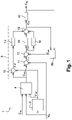
- the control method according to the invention implements a processing chain 1 which, from the ground speed setpoint Cvs, controls the speed of the aircraft during the taxiing phases of the aircraft.
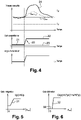
- the ground speed setpoint Cvs illustrated here is a step function which corresponds to a maneuver towards the rear of the aircraft. Such a rearward maneuver is relatively critical, since the brake pedal should not be actuated to avoid tilting the aircraft.
- the ground speed setpoint Cvs changes at a start time t0 from zero speed to a constant target speed Vc (the target speed Vc is negative here), then changes to the stop time t1 from the target speed Vc to a zero speed.
- the electrical control module generates, from the ground speed setpoint Cvs, a torque command Coc to be applied to the wheels of the main landing gear.
- the torque command Coc is transmitted to the electric power module.
- the electric power module generates from the torque control Coc an electric control current and transmits it to the electric motor.
- the effective speed of the aircraft is measured by aircraft speed sensors.
- the speed sensors are located at the front of the aircraft, near the cockpit.
- the speed control of the aircraft is therefore a control of a speed of the front of the aircraft, which allows the pilot to directly feel the effects of the speed control.
- the measured speed Vm is processed by a speed measurement processing block 2 of the processing chain 1.
- the speed measurement processing block 2 comprises a filter intended to remove measurement noise present in the measured speed Vm, and therefore to prevent oscillations resulting from the measurement noise from propagating in the processing chain 1.
- the cut-off frequency of this filter is directly proportional to the measured speed Vm: the higher the measured speed Vm, the greater the filtering .
- the delay induced by the filtering at low or very low speed is thus limited, and the stability of the processing chain 1 is improved.
- a filtered measured speed Vmf is obtained at the output of the speed measurement processing block 2.
- ground speed setpoint Cvs is itself processed by a speed setpoint processing block 4, which transforms the ground speed setpoint Cvs into an optimized speed setpoint Cvo.
- a control loop 3, which has the optimized speed setpoint Cvo as its setpoint, is then implemented.
- the optimized speed setpoint Cvo presents a curve as a function of time having a predefined profile comprising a plurality of linear portions.
- the predefined profile comprises a linear start portion 5, two linear acceleration portions 6, a linear target speed portion 7 and two linear deceleration portions 8.
- the linear starting portion 5 has a zero slope and defines a predetermined speed level lower than the target speed Vc.
- the predetermined speed level is used to ensure that the aircraft can be set in motion despite the possible occurrence of a so-called “square wheel” phenomenon and this instantaneously.
- the wheels tend to have, at their circumference in contact with the runway, a shape corresponding to the profile of the runway.
- the wheel (and the track) then opposes a resistance to the movement of the aircraft.
- it is necessary to apply a torque at least equal to a breakaway torque when starting.
- the predetermined speed plateau makes it possible to generate, in the regulation loop 3, a large speed error ⁇ v (equal to the difference between the optimized speed setpoint Cvo and the measured speed Vm) which produces a large torque command Coc, at the least equal to the breakaway torque. In the absence of this predetermined speed level, there is a risk that the actual movement of the aircraft will not begin until several seconds after this movement is commanded.
- the linear start portion 5 is followed by the two linear acceleration portions 6 which bring the optimized speed setpoint Cvo to a value equal to that of the ground speed setpoint Cvs (ie to the target speed Vc).
- first linear acceleration portion 6a which brings the optimized speed setpoint Cvo to a value within a precision interval Ip after a response time Tr
- second linear portion acceleration 6b which brings the optimized speed setpoint Cvo to a value equal to that of the setpoint ground speed Cvs (i.e. the target speed Vc).
- the precision interval Ip and the response time Tr are “specified”, that is to say they meet the aircraft manufacturer's specifications which make it possible to ensure the taxiing performance of the aircraft.
- the first linear acceleration portion 6a thus makes it possible to obtain a measured speed Vm which is in the precision interval Ip after the response time Tr.
- the slope of the second linear portion of acceleration 6b is adjusted to ensure the stabilization of the ground speed of the aircraft, so that the measured speed Vm has an overshoot value (value commonly designated by the English term "overshoot” ) minimum in relation to the ground speed setpoint Cvo. It is noted that, as the measured speed Vm is already in the precision interval Ip, the value of the slope of the second linear portion of acceleration 6b is not linked to a specification. The slope can also be relatively low, and is not taken into account in the response time Tr of the processing chain 1.
- the slope of the first linear acceleration portion 6a and the slope of the second linear acceleration portion 6b are therefore each a function of the aircraft manufacturer's specifications and/or of the dynamic error of the processing chain 1 and/or of the ground speed setpoint Cvs. This ensures that the torque control Coc is not oversized, and the mechanical stresses undergone by the main landing gear and the electric taxiing system are reduced.
- the aircraft's speed is stabilized at the target value Vc, until the moment t1 when the ground speed setpoint Cvs is cancelled.
- the target speed linear portion 7 is followed by the two linear deceleration portions 8 which, when the ground speed setpoint Cvs becomes zero, bring the optimized speed setpoint Cvo to a zero value.
- first linear deceleration portion 8a which brings the optimized speed setpoint Cvo to a value included in the precision interval Ip after the response time Tr
- second linear portion of deceleration 8b which brings the optimized speed setpoint Cvo to a zero value
- the definition of the first linear deceleration portion 8a is therefore similar to the definition of the first linear acceleration portion 6a.
- the second linear deceleration portion 8b is very important, since it makes it possible to stop the aircraft progressively and to give the electric taxiing system satisfactory and sufficient precision to complete the maneuver of the aircraft.
- the slope of the first linear deceleration portion 8a and the slope of the second linear deceleration portion 8b are therefore each a function of the aircraft manufacturer's specifications and/or of the dynamic error of the processing chain 1 and/or of the ground speed setpoint Cvs.
- the predefined profile which has just been described, comprising a plurality of linear portions, makes it possible to adjust the processing chain 1 so as to obtain a speed control having a fast response time, good stability and low static error.
- Regulation loop 3 comprises a first subtractor 10, a second subtractor 11, a third subtractor 12, an adder 13, as well as a proportional block 14, an integrator block 15 and a differentiator block 16.
- the proportional block 14, the block integrator 15 and differentiator block 16 form a proportional, integral, derivative regulator.
- the first subtractor 10 subtracts from the optimized speed setpoint Cvo the filtered measured speed Vmf to produce a filtered speed error ⁇ vf.
- the filtered speed error ⁇ vf is applied at the input of the proportional block 14.
- the speed error be filtered at the input of the proportional block 14, to avoid obtaining at the output of the proportional block 14 a noise level equivalent to that present in the measured speed Vm. Because of this filtering, the proportional block 14 however risks generating a delay and creating instability in the processing chain 1.
- a proportional block 14 is therefore chosen which has a proportional gain 20 depending on the angle of orientation of the steerable part of the auxiliary landing gear of the aircraft.
- the speed control of the aircraft is a control of a speed of the front of the aircraft
- the controlled speed depends on the angle of orientation.
- a low value 21 of the proportional gain 20 when the orientation angle is close to zero the sensitivity to the noise of the speed measurement (present in the measured speed Vs) is reduced.
- This low value 21 of the proportional gain 20 is only determined by the characteristics of the acceleration phases (and therefore linear portions of acceleration 6) and deceleration (and therefore linear portions of deceleration 8) to obtain the required response time Tr.
- the proportional gain 20 of the proportional block 14 is then increased and reaches a high value 22 which allows the processing chain 1 to be more robust to disturbances, and which makes it possible to keep the measured speed Vm of the aircraft within the interval specified Ip precision.
- the high value 22 of the proportional gain 20 is determined so that the processing chain 1 is robust to orientation maneuvers at stabilized speed (that is to say at the value of the target speed Vc).
- the proportional gain 20 of the proportional block 14 depends on the orientation angle by presenting a low value 21 when the orientation angle is low and a high value 22 when the orientation angle is greater, the reactivity of the processing chain 1 and the measured speed Vm is maintained within the precision interval Ip.
- the second subtractor 11 subtracts from the optimized speed setpoint Cvo the measured speed Vm (unfiltered) to produce the speed error ⁇ v.
- the third subtractor 12 subtracts from the speed error ⁇ v the output of an anti-runaway block 30 (which will be described later in this document) to produce a corrected speed error ⁇ vc.
- the corrected speed error ⁇ vc is applied at the input of the integrator block 15.
- the input of the integrator block 15 does not require filtering, because the integrator block 15 constitutes a filter in itself.
- the integrator block 15 filters the noise present in the measured speed Vm without adding any delay due to speed processing.
- the speed error ⁇ v is moreover corrected by the anti-runaway block 30.
- the integrator gain 31 of the integrator block 15 depends on the absolute corrected speed error
- a high integrator gain 31 is used to make the processing chain 1 more reactive and to obtain the specified response time Tr.
- the level of integration required is less important for the dynamic behavior. Integration mainly compensates for static error. Also, as is the case with proportional gain 20, the low value of the integrator gain 31 at stabilized speed makes it possible to reduce the sensitivity to the noise present in the measured speed Vm.
- the corrected speed error ⁇ vc is also applied at the input of the differentiator block 16. Again, it is noted that the input of the differentiator block 16 does not require filtering, since the differentiator block 16 constitutes a filter in itself.
- the differentiator block 16 filters the noise present in the measured speed Vm without adding any delay due to speed processing.
- the speed error ⁇ v is moreover corrected by the anti-runaway block 30.
- the differentiator gain 32 of the differentiator block depends on the absolute corrected speed error
- the differentiator block 16 can produce calculation noises when the absolute corrected velocity error
- Adder 13 adds the output of proportional block 14, the output of integrator block 15 and the output of differentiator block 16 to obtain a regulated torque command Ccr at the output of regulation loop 3.
- the regulated torque command Ccr is applied at the input of a protection block 40 to obtain the torque command Coc.
- the protection block 40 here implements slope and saturation limitation functions.
- the anti-runaway block 30 implements an anti-runaway function (function commonly referred to by the English term “anti wind-up”).
- the anti-runaway block 30, which receives the regulated torque command Ccr and the torque command Coc, produces an anti-runaway torque Cae defined as being equal to the difference between the last regulated torque command Ccr and the last Coc torque order.
- the anti-runaway torque Cae can be weighted by a weighting coefficient if necessary.
- the anti-runaway function is a feedback anti-runaway function. It makes it possible to keep the output of the integrator block 15 and the output of the differentiator block 16 outside the saturation zones. A good reactivity of the processing chain 1 is thus preserved, since it is not necessary to reduce the filtering levels.
- the speed sensors are located at the front of the aircraft, the sensors may be located in other locations, and may for example include an electric motor speed sensor, a speed of a wheel of a main undercarriage or an auxiliary undercarriage.
Description
L'invention concerne le domaine du taxiage ou roulage des aéronefs.The invention relates to the field of aircraft taxiing or taxiing.
Un système de taxiage installé sur un aéronef permet de déplacer l'aéronef durant les phases de taxiage de manière autonome, c'est-à-dire en évitant l'usage des moteurs principaux de l'aéronef.A taxiing system installed on an aircraft makes it possible to move the aircraft during the taxiing phases in an autonomous manner, that is to say by avoiding the use of the main engines of the aircraft.
Dans un système de taxiage électrique, des roues portées par un ou plusieurs atterrisseurs sont entraînées en rotation, durant les phases de taxiage, par des actionneurs comportant des moteurs électriques.In an electric taxiing system, wheels carried by one or more undercarriages are driven in rotation, during the taxiing phases, by actuators comprising electric motors.
Lors des phases de taxiage d'un aéronef utilisant un tel système de taxiage, l'aéronef est donc mu par le ou les atterrisseurs portant les roues entraînées en rotation par le système de taxiage.During the taxiing phases of an aircraft using such a taxiing system, the aircraft is therefore moved by the landing gear(s) carrying the wheels driven in rotation by the taxiing system.
Il est important de contrôler précisément en vitesse un tel système de taxiage, notamment pendant les phases de manœuvre de l'aéronef (vers l'avant ou vers l'arrière) lorsque la vitesse au sol de l'aéronef est faible.It is important to precisely control the speed of such a taxiing system, in particular during the maneuvering phases of the aircraft (forwards or backwards) when the ground speed of the aircraft is low.
Typiquement, pour une vitesse au sol de l'aéronef de 2 nœuds, la précision requise est de 10%, soit 0,2 nœuds, soit environ 10cm/s. Une telle précision est relativement complexe à obtenir, d'autant que les mesures de vitesse au sol sont soumises à diverses sources d'imprécision : imprécision du ou des capteurs, résolution des données, délais de transmission, etc. La précision doit par ailleurs être robuste à de grandes variations d'efforts auxquels est soumis le système de taxiage, car la masse d'un aéronef peut varier du simple au double, et les effets de la pente de la piste sur laquelle roule l'aéronef sont importants.Typically, for an aircraft ground speed of 2 knots, the accuracy required is 10%, or 0.2 knots, or approximately 10 cm/s. Such precision is relatively complex to obtain, especially since ground speed measurements are subject to various sources of inaccuracy: inaccuracy of the sensor(s), data resolution, transmission delays, etc. Accuracy must also be robust to large variations in the forces to which the taxiing system is subjected, since the mass of an aircraft can vary by a factor of two, and the effects of the slope of the runway on which the aircraft are important.
Le document
Le document
L'invention a pour objet d'améliorer la précision du contrôle à basse vitesse d'un système de taxiage électrique d'un aéronef.The object of the invention is to improve the precision of the control at low speed of an electric taxiing system of an aircraft.
En vue de la réalisation de ce but, on propose un procédé de commande d'un système de taxiage électrique adapté à déplacer un aéronef au cours du taxiage de l'aéronef, comprenant les étapes de :
- générer une consigne de vitesse au sol de l'aéronef ;
- transformer la consigne de vitesse au sol en une consigne de vitesse optimisée présentant une courbe en fonction du temps ayant un profil prédéfini comportant une pluralité de portions linéaires ayant chacune une pente fonction de la consigne de vitesse au sol ;
- mettre en œuvre une boucle de régulation ayant pour consigne la consigne de vitesse optimisée ;
- générer une commande du système de taxiage électrique à partir d'une sortie de la boucle de régulation.
- generating an aircraft ground speed setpoint;
- transforming the ground speed setpoint into an optimized speed setpoint having a curve as a function of time having a predefined profile comprising a plurality of linear portions each having a slope depending on the ground speed setpoint;
- implement a control loop having the optimized speed setpoint as setpoint;
- generating a command of the electric taxiing system from an output of the regulation loop.
En transformant la consigne de vitesse au sol en une consigne de vitesse optimisée présentant une courbe en fonction du temps ayant un profil prédéfini, on impose ledit profil prédéfini en entrée de la boucle de régulation, et on évite ainsi toute instabilité dans la boucle de régulation. Il n'est en particulier pas nécessaire de mettre en œuvre un calcul d'accélération qui est une source d'imprécision importante.By transforming the ground speed setpoint into an optimized speed setpoint having a curve as a function of time having a predefined profile, said predefined profile is imposed at the input of the regulation loop, and any instability in the regulation loop is thus avoided. . In particular, it is not necessary to implement an acceleration calculation which is a significant source of inaccuracy.
L'invention sera mieux comprise à la lumière de la description qui suit d'un mode de mise en œuvre particulier non limitatif de l'invention.The invention will be better understood in the light of the following description of a particular non-limiting mode of implementation of the invention.
Il sera fait référence aux dessins annexés, parmi lesquels :
- la
figure 1 représente une chaîne de traitement mise en œuvre dans un procédé de commande d'un système de taxiage électrique selon l'invention ; - la
figure 2 représente des courbes d'une consigne de vitesse au sol, d'une consigne de vitesse optimisée, et d'une vitesse mesurée ; - la
figure 3 représente une courbe d'un gain proportionnel d'un bloc proportionnel d'une boucle de régulation de la chaîne de traitement ; - la
figure 4 représente des courbes de vitesses mesurées, de gains proportionnels du bloc proportionnel et d'un angle d'orientation ; - la
figure 5 représente une courbe d'un gain intégrateur d'un bloc intégrateur de la boucle de régulation de la chaîne de traitement ; - la
figure 6 représente une courbe d'un gain dérivateur d'un bloc dérivateur de la boucle de régulation de la chaîne de traitement.
- the
figure 1 represents a processing chain implemented in a method for controlling an electric taxiing system according to the invention; - the
picture 2 - the
picture 3 - the
figure 4 represents curves of measured speeds, of proportional gains of the proportional block and of an orientation angle; - the
figure 5 represents a curve of an integrator gain of an integrator block of the regulation loop of the processing chain; - the
figure 6 represents a curve of a derivative gain of a derivative block of the regulation loop of the processing chain.
Le procédé de commande d'un système de taxiage électrique selon l'invention est ici mis en œuvre sur un aéronef.The method for controlling an electric taxiing system according to the invention is here implemented on an aircraft.
L'aéronef comporte un atterrisseur principal et un atterrisseur auxiliaire qui est situé à l'avant de l'aéronef.The aircraft comprises a main landing gear and an auxiliary landing gear which is located at the front of the aircraft.
L'atterrisseur principal comprend une tige montée à coulissement dans un caisson de l'atterrisseur et portant deux roues.The main undercarriage comprises a rod slidably mounted in a casing of the undercarriage and carrying two wheels.
Le système de taxiage électrique agit sur les roues de l'atterrisseur principal pour déplacer l'aéronef de manière autonome au cours du taxiage de l'aéronef.The electric taxiing system acts on the wheels of the main landing gear to move the aircraft autonomously during the taxiing of the aircraft.
L'atterrisseur auxiliaire comporte une partie orientable selon un angle d'orientation, qui est commandée pour diriger l'aéronef au cours du taxiage de l'aéronef.The auxiliary landing gear comprises a part that can be steered according to an orientation angle, which is controlled to steer the aircraft during the taxiing of the aircraft.
Le système de taxiage électrique comporte ici un actionneur comprenant un moteur électrique, un module électrique de puissance (couramment appelé calculateur, contrôleur, électronique de puissance, etc.) et un module électrique de commande (couramment appelé calculateur, contrôleur, électronique de commande, etc.). Le module électrique de puissance et le module électrique de commande peuvent bien sûr être intégrés au sein d'une même unité électrique.The electric taxiing system here comprises an actuator comprising an electric motor, an electric power module (commonly called a computer, controller, power electronics, etc.) and an electric control module (commonly called a computer, controller, control electronics, etc.). The electrical power module and the electrical control module can of course be integrated within the same electrical unit.
En référence aux
La consigne de vitesse au sol Cvs illustrée ici est une fonction échelon qui correspond à une manœuvre vers l'arrière de l'aéronef. Une telle manœuvre vers l'arrière est relativement critique, car il convient de ne pas actionner la pédale de frein pour éviter d'incliner l'aéronef. La consigne de vitesse au sol Cvs passe à un temps de démarrage t0 d'une vitesse nulle à une vitesse cible Vc constante (la vitesse cible Vc est ici négative), puis passe au temps d'arrêt t1 de la vitesse cible Vc à une vitesse nulle.The ground speed setpoint Cvs illustrated here is a step function which corresponds to a maneuver towards the rear of the aircraft. Such a rearward maneuver is relatively critical, since the brake pedal should not be actuated to avoid tilting the aircraft. The ground speed setpoint Cvs changes at a start time t0 from zero speed to a constant target speed Vc (the target speed Vc is negative here), then changes to the stop time t1 from the target speed Vc to a zero speed.
Le module électrique de commande génère, à partir de la consigne de vitesse au sol Cvs, une commande de couple Coc à appliquer sur les roues de l'atterrisseur principal. La commande de couple Coc est transmise au module électrique de puissance. Le module électrique de puissance génère à partir de la commande de couple Coc un courant électrique de commande et le transmet au moteur électrique.The electrical control module generates, from the ground speed setpoint Cvs, a torque command Coc to be applied to the wheels of the main landing gear. The torque command Coc is transmitted to the electric power module. The electric power module generates from the torque control Coc an electric control current and transmits it to the electric motor.
La vitesse effective de l'aéronef est mesurée par des capteurs de vitesse de l'aéronef. Les capteurs de vitesse sont situés à l'avant de l'aéronef, à proximité du cockpit. Le contrôle en vitesse de l'aéronef est donc un contrôle d'une vitesse de l'avant de l'aéronef, ce qui permet au pilote de ressentir directement les effets du contrôle en vitesse.The effective speed of the aircraft is measured by aircraft speed sensors. The speed sensors are located at the front of the aircraft, near the cockpit. The speed control of the aircraft is therefore a control of a speed of the front of the aircraft, which allows the pilot to directly feel the effects of the speed control.
La vitesse mesurée Vm est traitée par un bloc de traitement de mesure de vitesse 2 de la chaîne de traitement 1. Le bloc de traitement de mesure de vitesse 2 comporte un filtre destiné à supprimer un bruit de mesure présent dans la vitesse mesurée Vm, et donc à éviter que des oscillations résultant du bruit de mesure ne se propagent dans la chaîne de traitement 1. La fréquence de coupure de ce filtre est directement proportionnelle à la vitesse mesurée Vm : plus la vitesse mesurée Vm est élevée, plus le filtrage est important. On limite ainsi le retard induit par le filtrage à basse ou très basse vitesse, et on améliore la stabilité de la chaîne de traitement 1. Une vitesse mesurée filtrée Vmf est obtenue en sortie du bloc de traitement de mesure de vitesse 2.The measured speed Vm is processed by a speed
La consigne de vitesse au sol Cvs est quant à elle traitée par un bloc de traitement de consigne de vitesse 4, qui transforme la consigne de vitesse au sol Cvs en une consigne de vitesse optimisée Cvo. Une boucle de régulation 3, qui a pour consigne la consigne de vitesse optimisée Cvo, est alors mise en œuvre.The ground speed setpoint Cvs is itself processed by a speed
La consigne de vitesse optimisée Cvo présente une courbe en fonction du temps ayant un profil prédéfini comportant une pluralité de portions linéaires.The optimized speed setpoint Cvo presents a curve as a function of time having a predefined profile comprising a plurality of linear portions.
Le profil prédéfini comporte une portion linéaire de démarrage 5, deux portions linéaires d'accélération 6, une portion linéaire de vitesse cible 7 et deux portions linéaires de décélération 8.The predefined profile comprises a
La portion linéaire de démarrage 5 présente une pente nulle et définit un palier de vitesse prédéterminé inférieur à la vitesse cible Vc.The
Le palier de vitesse prédéterminé est utilisé pour assurer que l'aéronef peut être mis en mouvement malgré la survenue possible d'un phénomène dit de « roue carrée » et ce de manière instantanée. Lorsque l'aéronef est maintenu à l'arrêt au sol pendant un certain temps, les roues tendent à présenter, au niveau de leur circonférence au contact de la piste, une forme correspondant au profil de la piste. La roue (et la piste) oppose alors une résistance au déplacement de l'aéronef. Il convient, pour déplacer l'aéronef de manière instantanée, d'appliquer au démarrage un couple au moins égal à un couple de décollement. Le palier de vitesse prédéterminé permet de générer, dans la boucle de régulation 3, une erreur de vitesse εv importante (égale à la différence entre la consigne de vitesse optimisée Cvo et la vitesse mesurée Vm) qui produit une commande de couple Coc importante, au moins égale au couple de décollement. En l'absence de ce palier de vitesse prédéterminé, il existe un risque que le déplacement effectif de l'aéronef ne débute que plusieurs secondes après que ce déplacement ne soit commandé.The predetermined speed level is used to ensure that the aircraft can be set in motion despite the possible occurrence of a so-called “square wheel” phenomenon and this instantaneously. When the aircraft is kept stationary on the ground for a certain time, the wheels tend to have, at their circumference in contact with the runway, a shape corresponding to the profile of the runway. The wheel (and the track) then opposes a resistance to the movement of the aircraft. To move the aircraft instantaneously, it is necessary to apply a torque at least equal to a breakaway torque when starting. The predetermined speed plateau makes it possible to generate, in the
La portion linéaire de démarrage 5 est suivie par les deux portions linéaires d'accélération 6 qui amènent la consigne de vitesse optimisée Cvo à une valeur égale à celle de la consigne de vitesse au sol Cvs (soit à la vitesse cible Vc).The
Parmi les deux portions linéaires d'accélération 6, on trouve une première portion linéaire d'accélération 6a qui amène la consigne de vitesse optimisée Cvo à une valeur comprise dans un intervalle de précision Ip après un temps de réponse Tr, et une deuxième portion linéaire d'accélération 6b qui amène la consigne de vitesse optimisée Cvo à une valeur égale à celle de la consigne de vitesse au sol Cvs (soit à la vitesse cible Vc).Among the two linear acceleration portions 6, there is a first
L'intervalle de précision Ip et le temps de réponse Tr sont « spécifiés », c'est-à-dire qu'ils répondent à des spécifications de l'avionneur qui permettent d'assurer les performances du taxiage de l'aéronef.The precision interval Ip and the response time Tr are “specified”, that is to say they meet the aircraft manufacturer's specifications which make it possible to ensure the taxiing performance of the aircraft.
La première portion linéaire d'accélération 6a permet ainsi d'obtenir une vitesse mesurée Vm qui soit dans l'intervalle de précision Ip après le temps de réponse Tr.The first
La pente de la deuxième portion linéaire d'accélération 6b est réglée pour assurer la stabilisation de la vitesse au sol de l'aéronef, de sorte que la vitesse mesurée Vm présente une valeur de dépassement (valeur communément désignée par le terme anglais « overshoot ») minimale par rapport à la consigne de vitesse au sol Cvo. On note que, comme la vitesse mesurée Vm est déjà dans l'intervalle de précision Ip, la valeur de la pente de la deuxième portion linéaire d'accélération 6b n'est pas liée à une spécification. La pente peut par ailleurs être relativement faible, et n'est pas prise en compte dans le temps de réponse Tr de la chaîne de traitement 1.The slope of the second linear portion of
La pente de la première portion linéaire d'accélération 6a et la pente de la deuxième portion linéaire d'accélération 6b sont donc chacune fonction des spécifications de l'avionneur et/ou de l'erreur dynamique de la chaîne de traitement 1 et/ou de la consigne de vitesse au sol Cvs. On assure ainsi que la commande en couple Coc n'est pas surdimensionnée, et on réduit les contraintes mécaniques subies par l'atterrisseur principal et le système de taxiage électrique.The slope of the first
La portion linéaire de vitesse cible 7, qui suit la première portion linéaire d'accélération 6a et la deuxième portion linéaire d'accélération 6b, présente une pente nulle. La vitesse de l'aéronef est stabilisée à la valeur cible Vc, jusqu'au moment t1 où la consigne de vitesse au sol Cvs s'annule.The target speed
La portion linéaire de vitesse cible 7 est suivie par les deux portions linéaires de décélération 8 qui, lorsque la consigne de vitesse au sol Cvs devient nulle, amènent la consigne de vitesse optimisée Cvo à une valeur nulle.The target speed
Parmi les deux portions linéaires de décélération 8, on trouve une première portion linéaire de décélération 8a qui amène la consigne de vitesse optimisée Cvo à une valeur comprise dans l'intervalle de précision Ip après le temps de réponse Tr, et une deuxième portion linéaire de décélération 8b qui amène la consigne de vitesse optimisée Cvo à une valeur nulle.Among the two linear deceleration portions 8, there is a first
La définition de la première portion linéaire de décélération 8a est donc similaire à la définition de la première portion linéaire d'accélération 6a.The definition of the first
La deuxième portion linéaire de décélération 8b est très importante, puisqu'elle permet de stopper l'aéronef de manière progressive et de conférer au système de taxiage électrique une précision satisfaisante et suffisante pour réaliser la fin de la manœuvre de l'aéronef.The second
La pente de la première portion linéaire de décélération 8a et la pente de la deuxième portion linéaire de décélération 8b sont donc chacune fonction des spécifications de l'avionneur et/ou de l'erreur dynamique de la chaîne de traitement 1 et/ou de la consigne de vitesse au sol Cvs.The slope of the first
On note qu'une portion linéaire équivalente à la portion linéaire de démarrage 5 n'est pas nécessaire puisque le phénomène de type « roue carrée » aide au freinage (action recherchée à cet instant).It is noted that a linear portion equivalent to the
Le profil prédéfini qui vient d'être décrit, comportant une pluralité de portions linéaires, permet de régler la chaîne de traitement 1 de manière à obtenir un contrôle en vitesse ayant un temps de réponse rapide, une bonne stabilité et une erreur statique faible.The predefined profile which has just been described, comprising a plurality of linear portions, makes it possible to adjust the
La boucle de régulation 3 comporte un premier soustracteur 10, un deuxième soustracteur 11, un troisième soustracteur 12, un sommateur 13, ainsi qu'un bloc proportionnel 14, un bloc intégrateur 15 et un bloc dérivateur 16. Le bloc proportionnel 14, le bloc intégrateur 15 et le bloc dérivateur 16 forment un régulateur proportionnel, intégral, dérivé.
Le premier soustracteur 10 retranche à la consigne de vitesse optimisée Cvo la vitesse mesurée filtrée Vmf pour produire une erreur de vitesse filtrée εvf.The
L'erreur de vitesse filtrée εvf est appliquée en entrée du bloc proportionnel 14.The filtered speed error εvf is applied at the input of the
Il est préférable que l'erreur de vitesse soit filtrée en entrée du bloc proportionnel 14, pour éviter d'obtenir en sortie du bloc proportionnel 14 un niveau de bruit équivalent à celui présent dans la vitesse mesurée Vm. A cause de ce filtrage, le bloc proportionnel 14 risque cependant de générer un retard et créer de l'instabilité dans la chaîne de traitement 1.It is preferable that the speed error be filtered at the input of the
En référence à la
En effet, comme le contrôle en vitesse de l'aéronef est un contrôle d'une vitesse de l'avant de l'aéronef, la vitesse contrôlée dépend de l'angle d'orientation. En définissant une valeur faible 21 du gain proportionnel 20 lorsque l'angle d'orientation est proche de zéro, on diminue la sensibilité au bruit de la mesure de vitesse (présent dans la vitesse mesurée Vs). Cette valeur faible 21 du gain proportionnel 20 est seulement déterminée par les caractéristiques des phases d'accélération (et donc des portions linéaires d'accélération 6) et de décélération (et donc des portions linéaires de décélération 8) pour obtenir le temps de réponse Tr requis.Indeed, as the speed control of the aircraft is a control of a speed of the front of the aircraft, the controlled speed depends on the angle of orientation. By defining a
Lorsque l'angle d'orientation augmente (en valeur absolue), la dynamique de l'avant de l'aéronef augmente aussi. Le gain proportionnel 20 du bloc proportionnel 14 est alors augmenté et atteint une valeur élevée 22 qui permet à la chaîne de traitement 1 d'être plus robuste aux perturbations, et qui permet de garder la vitesse mesurée Vm de l'aéronef dans l'intervalle de précision Ip spécifié. La valeur élevée 22 du gain proportionnel 20 est déterminée pour que la chaîne de traitement 1 soit robuste aux manœuvres d'orientation à vitesse stabilisée (c'est à dire à la valeur de la vitesse cible Vc).When the orientation angle increases (in absolute value), the dynamics of the front of the aircraft also increases. The
L'intérêt d'utiliser un gain proportionnel 20 qui soit fonction de l'angle d'orientation est illustré sur la
On voit que, lorsque le gain proportionnel utilisé est un gain constant 23 de valeur faible, la dynamique d'une manœuvre d'orientation est trop importante pour la chaîne de traitement 1, car l'augmentation de vitesse requise est trop importante. La courbe de vitesse mesurée 24 présente alors une valeur de dépassement importante par rapport à l'intervalle de précision Ip.It can be seen that, when the proportional gain used is a
Lorsque le gain proportionnel 20 du bloc proportionnel 14 dépend de l'angle d'orientation en présentant une valeur faible 21 lorsque l'angle d'orientation est faible et une valeur élevée 22 lorsque l'angle d'orientation est plus important, on améliore la réactivité de la chaîne de traitement 1 et on maintient la vitesse mesurée Vm dans l'intervalle de précision Ip.When the
Il n'est pas nécessaire que l'angle d'orientation soit très important pour observer ce phénomène : un angle de 40°, fréquemment obtenu lors d'une manœuvre de repoussage de l'aéronef, est suffisant.It is not necessary for the angle of orientation to be very large to observe this phenomenon: an angle of 40°, frequently obtained during a maneuver of push back of the aircraft, is sufficient.
Le deuxième soustracteur 11 retranche à la consigne de vitesse optimisée Cvo la vitesse mesurée Vm (non filtrée) pour produire l'erreur de vitesse εv. Le troisième soustracteur 12 retranche à l'erreur de vitesse εv la sortie d'un bloc d'anti-emballement 30 (qui sera décrit plus loin dans ce document) pour produire une erreur de vitesse corrigée εvc.The
L'erreur de vitesse corrigée εvc est appliquée en entrée du bloc intégrateur 15.The corrected speed error εvc is applied at the input of the
On note que l'entrée du bloc intégrateur 15 ne nécessite pas de filtrage, car le bloc intégrateur 15 constitue un filtre en lui-même. Le bloc intégrateur 15 filtre le bruit présent dans la vitesse mesurée Vm sans ajouter de retard dû à un traitement de la vitesse. L'erreur de vitesse εv est par ailleurs corrigée par le bloc d'anti-emballement 30.It is noted that the input of the
En référence à la
Le gain intégrateur 31 du bloc intégrateur 15 est : I(p)=K/p.The
Lorsque l'erreur de vitesse corrigée absolue |εvc| est élevée, c'est à dire pendant les phases d'accélération et de décélération, un gain intégrateur 31 élevé est utilisé pour rendre la chaîne de traitement 1 plus réactive et pour obtenir le temps de réponse Tr spécifié.When the absolute corrected velocity error |εvc| is high, ie during the acceleration and deceleration phases, a
Lorsque l'erreur de vitesse corrigée absolue |εvc| est faible, c'est à dire lorsque la vitesse mesurée Vm est proche de la consigne de vitesse optimisée Cvo, le niveau d'intégration requis est moins important pour le comportement dynamique. L'intégration permet principalement de compenser l'erreur statique. De plus, comme c'est le cas avec le gain proportionnel 20, la valeur faible du gain intégrateur 31 à vitesse stabilisée permet de réduire la sensibilité au bruit présent dans la vitesse mesurée Vm.When the absolute corrected velocity error |εvc| is low, ie when the measured speed Vm is close to the optimized speed setpoint Cvo, the level of integration required is less important for the dynamic behavior. Integration mainly compensates for static error. Also, as is the case with
L'erreur de vitesse corrigée εvc est aussi appliquée en entrée du bloc dérivateur 16. A nouveau, on note que l'entrée du bloc dérivateur 16 ne nécessite pas de filtrage, car le bloc dérivateur 16 constitue un filtre en lui-même. Le bloc dérivateur 16 filtre le bruit présent dans la vitesse mesurée Vm sans ajouter de retard dû à un traitement de la vitesse. L'erreur de vitesse εv est par ailleurs corrigée par le bloc d'anti-emballement 30.The corrected speed error εvc is also applied at the input of the
En référence à la
Le gain dérivateur 32 du bloc dérivateur 16 est : D(p)=K*p/(1+a*K*p).The
Lorsque l'erreur de vitesse corrigée absolue |εvc| est élevée, c'est à dire pendant les phases d'accélération et de décélération, une valeur élevée du gain dérivateur 32 est utilisée pour rendre la chaîne de traitement 1 plus réactive et pour stabiliser la chaîne de traitement en évitant les valeurs de dépassement importantes.When the absolute corrected velocity error |εvc| is high, that is to say during the acceleration and deceleration phases, a high value of the differentiator gain 32 is used to make the
Lorsque l'erreur de vitesse corrigée absolue |εvc| est faible, c'est à dire lorsque la vitesse mesurée Vm est proche de la consigne de vitesse optimisée Cvo, le niveau de dérivation requis est moins important pour le comportement dynamique. En outre, le bloc dérivateur 16 peut produire des bruits de calcul lorsque l'erreur de vitesse corrigée absolue |εvc| est très faible. Par conséquent, le bloc dérivateur 16 n'est pas utilisé lorsque la vitesse mesurée Vm est très proche de la consigne de vitesse optimisée Cvo. Plus précisément, comme cela est visible sur la
Le sommateur 13 additionne la sortie du bloc proportionnel 14, la sortie du bloc intégrateur 15 et la sortie du bloc dérivateur 16 pour obtenir une commande de couple régulé Ccr en sortie de la boucle de régulation 3.
La commande de couple régulé Ccr est appliquée en entrée d'un bloc de protection 40 pour obtenir la commande de couple Coc. Le bloc de protection 40 met ici en œuvre des fonctions de limitation de pente et de saturation.The regulated torque command Ccr is applied at the input of a
Le bloc d'anti-emballement 30 met en œuvre une fonction d'anti-emballement (fonction communément désignée par le terme anglais « anti wind-up »). Le bloc d'anti-emballement 30, qui reçoit la commande de couple régulé Ccr et la commande de couple Coc, produit un couple d'anti-emballement Cae défini comme étant égal à la différence entre la dernière commande de couple régulé Ccr et la dernière commande de couple Coc. Le couple d'anti-emballement Cae peut être pondéré par un coefficient de pondération si nécessaire. La fonction d'anti-emballement est une fonction d'anti-emballement par rétroaction. Elle permet de garder la sortie du bloc intégrateur 15 et la sortie du bloc dérivateur 16 hors des zones de saturation. On conserve ainsi une bonne réactivité de la chaîne de traitement 1, car il n'est pas nécessaire de réduire les niveaux de filtrage.The
Bien entendu, l'invention n'est pas limitée au mode de réalisation décrit mais englobe toute variante entrant dans le champ de l'invention telle que définie par les revendications.Of course, the invention is not limited to the embodiment described but encompasses any variant falling within the scope of the invention as defined by the claims.
Bien que l'on ait décrit deux portions linéaires d'accélération (et de décélération), on pourra utiliser une seule portion linéaire d'accélération (et de décélération), ou bien un nombre différent de portions linéaire d'accélération (et de décélération).Although two linear portions of acceleration (and deceleration) have been described, a single linear portion of acceleration (and of deceleration), or a different number of linear portions of acceleration (and deceleration).
Bien que l'on ait indiqué que les capteurs de vitesse sont situés à l'avant de l'aéronef, les capteurs peuvent être situés à d'autres endroits, et peuvent par exemple comprendre un capteur de vitesse du moteur électrique, un capteur de vitesse d'une roue d'un atterrisseur principal ou d'un atterrisseur auxiliaire.Although it has been stated that the speed sensors are located at the front of the aircraft, the sensors may be located in other locations, and may for example include an electric motor speed sensor, a speed of a wheel of a main undercarriage or an auxiliary undercarriage.
On peut aussi effectuer un contrôle en vitesse sur la base d'une vitesse différente de la vitesse avant de l'aéronef, et bien sûr, générer en sortie de la chaîne de traitement une commande différente de la commande de couple.It is also possible to perform a speed control on the basis of a speed different from the forward speed of the aircraft, and of course, to generate at the output of the processing chain a command different from the torque command.
Claims (14)
- A control method for controlling an electrical taxiing system adapted to moving an aircraft while it is taxiing, the method comprising the steps of:- generating a ground speed setpoint (Cvs) for the aircraft;- transforming the ground speed setpoint (Cvs) into an optimized speed setpoint (Cvo);- implementing a regulator loop (3) having the optimized speed setpoint (Cvo) as its setpoint; and- generating a command (Coc) for the electrical taxiing system from an output of the regulator loop (3), characterized in that the optimized speed setpoint (Cvo) presents a curve as a function of time that has a predefined function comprising a plurality of linear portions (5, 6, 7, 8), each having a slope that is a function of the ground speed setpoint.
- A control method according to claim 1, wherein the plurality of linear portions comprises a starting linear portion (5) presenting a slope of zero and defining a predetermined speed level that is smaller than the ground speed setpoint (Cvs).
- A control method according to claim 2, wherein the starting linear portion (5) is followed by a plurality of acceleration linear portions (6) that bring the optimized speed setpoint (Cvo) to a value equal to the value of the ground speed setpoint (Cvs).
- A control method according to claim 2, wherein the plurality of acceleration linear portions comprises a first acceleration linear portion (6a) that brings the optimized speed setpoint (Cvo) to a value lying within a specified accuracy range (Ip) by the end of a specified response time (Tr), and a second acceleration linear portion (6b) that brings the optimized speed setpoint to a value equal to the value of the ground speed setpoint.
- A control method according to claim 1, wherein the plurality of linear portions includes a plurality of deceleration linear portions (8) that, when the ground speed setpoint becomes zero, bring the optimized speed setpoint to a value of zero.
- A control method according to claim 5, wherein the plurality of deceleration linear portions comprise a first deceleration linear portion (8a) that brings the optimized speed setpoint to a speed value lying within a specified accuracy range by the end of a specified response time, and a second deceleration linear portion (8b) that brings the optimized speed setpoint to a value of zero.
- A control method according to claim 1, wherein the regulator loop (3) comprises a proportional, integral, and derivative regulator having a proportional block (14), an integrator block (15), and a differentiator block (16).
- A control method according to claim 7, wherein a filtered speed error is applied as input to the proportional block (14).
- A control method according to claim 7, wherein the proportional block (14) presents gain that depends on a steering angle of a steerable portion of landing gear of the aircraft.
- A control method according to claim 7, wherein the integrator block (15) presents gain that depends on a speed error.
- A control method according to claim 7, wherein the differentiator block (16) presents gain that depends on a speed error.
- A control method according to claim 11, wherein the gain of the differentiator block (16) is zero when the speed error is zero.
- A control method according to claim 1, wherein the regulator loop includes an anti-windup block (30).
- A control method according to claim 1, wherein the command of the electrical taxiing system is a torque command for applying to wheels of the aircraft.
Applications Claiming Priority (1)
| Application Number | Priority Date | Filing Date | Title |
|---|---|---|---|
| FR1660977A FR3058821B1 (en) | 2016-11-14 | 2016-11-14 | METHOD FOR CONTROLLING AN ELECTRIC TAXIAGE SYSTEM |
Publications (2)
| Publication Number | Publication Date |
|---|---|
| EP3321758A1 EP3321758A1 (en) | 2018-05-16 |
| EP3321758B1 true EP3321758B1 (en) | 2022-10-19 |
Family
ID=57861077
Family Applications (1)
| Application Number | Title | Priority Date | Filing Date |
|---|---|---|---|
| EP17201267.6A Active EP3321758B1 (en) | 2016-11-14 | 2017-11-13 | A method of controlling an electrical taxiing system |
Country Status (4)
| Country | Link |
|---|---|
| US (1) | US10421536B2 (en) |
| EP (1) | EP3321758B1 (en) |
| CN (1) | CN108073070B (en) |
| FR (1) | FR3058821B1 (en) |
Families Citing this family (1)
| Publication number | Priority date | Publication date | Assignee | Title |
|---|---|---|---|---|
| FR3089493B1 (en) | 2018-12-11 | 2020-12-18 | Safran Landing Systems | Method of torque control of a device for driving the rotation of aircraft wheels |
Family Cites Families (7)
| Publication number | Priority date | Publication date | Assignee | Title |
|---|---|---|---|---|
| JPS63150711A (en) * | 1986-12-16 | 1988-06-23 | Shinko Electric Co Ltd | Control method for unmanned vehicle |
| US20060235610A1 (en) * | 2005-04-14 | 2006-10-19 | Honeywell International Inc. | Map-based trajectory generation |
| FR3015707B1 (en) * | 2013-12-20 | 2017-04-21 | Messier Bugatti Dowty | METHOD FOR CONTROLLING AN ELECTRIC MOTOR DRIVING ROTATION OF AN AIRCRAFT WHEEL |
| FR3022887B1 (en) * | 2014-06-25 | 2016-10-21 | Messier Bugatti Dowty | METHOD FOR MANAGING AN ELECTRIC MOTOR |
| DE102015202216A1 (en) * | 2014-09-19 | 2016-03-24 | Robert Bosch Gmbh | Method and device for operating a motor vehicle by specifying a desired speed |
| US9533756B2 (en) * | 2014-11-03 | 2017-01-03 | Borealis Technical Limited | Method for defining and controlling aircraft taxi profile |
| US9802716B2 (en) * | 2015-06-06 | 2017-10-31 | Borealis Technical Limited | Aircraft landing gear drive wheel identification system |
-
2016
- 2016-11-14 FR FR1660977A patent/FR3058821B1/en active Active
-
2017
- 2017-11-13 EP EP17201267.6A patent/EP3321758B1/en active Active
- 2017-11-13 US US15/811,354 patent/US10421536B2/en active Active
- 2017-11-14 CN CN201711121160.1A patent/CN108073070B/en active Active
Also Published As
| Publication number | Publication date |
|---|---|
| FR3058821A1 (en) | 2018-05-18 |
| CN108073070A (en) | 2018-05-25 |
| FR3058821B1 (en) | 2019-01-25 |
| EP3321758A1 (en) | 2018-05-16 |
| CN108073070B (en) | 2021-06-25 |
| US20180134377A1 (en) | 2018-05-17 |
| US10421536B2 (en) | 2019-09-24 |
Similar Documents
| Publication | Publication Date | Title |
|---|---|---|
| CA2928218C (en) | Control system for rotorcraft, associated rotorcraft and corresponding control method | |
| FR2761039A1 (en) | METHOD AND DEVICE FOR IMPLEMENTING A GUIDE SYSTEM OF A MOTOR VEHICLE | |
| FR3022340A1 (en) | METHOD AND DEVICE FOR DETERMINING AN AIRCRAFT CONTROL INSTRUCTION, COMPUTER PROGRAM PRODUCT AND ASSOCIATED AIRCRAFT | |
| FR3024867A1 (en) | CONTROL MEMBER CONTROL SYSTEM IN AERONAUTICAL ELECTRIC FLIGHT CONTROL SYSTEMS | |
| FR3020036A1 (en) | ACTUATOR SYSTEM FOR AN AIRCRAFT GOVERNOR. | |
| EP2957975B1 (en) | Method and device for controlling at least one actuator control system of an aircraft, related computer program product and aircraft | |
| EP3338147B1 (en) | System for controlling a controlled parameter | |
| WO2007006725A1 (en) | Method and device for lightening loads on the wing system of an aircraft in roll motion | |
| FR3018364A1 (en) | METHOD OF DETERMINING AN OBSTACLE AVIATION GUIDANCE LAW BY AN AIRCRAFT, COMPUTER PROGRAM PRODUCT, ELECTRONIC SYSTEM AND AIRCRAFT | |
| EP3321758B1 (en) | A method of controlling an electrical taxiing system | |
| FR2909463A1 (en) | Aircraft's i.e. transport aircraft, roll active controlling method, involves calculating deflection order on basis of value and effective values which comprise effective value of roll rate by using integration function | |
| EP1799529B1 (en) | Steering control for the rear wheels of a motor vehicle and an asymmetrical adherence braking situation | |
| EP2838791B1 (en) | Device and method for active control of a force feedback for a control device | |
| EP3341604B1 (en) | Servo system for controlling the position of an actuator in a motor vehicle | |
| FR2992072A1 (en) | AUTOMATICALLY CONTROLLED LACET AXIS METHOD FOR MECHANICAL FLIGHT CONTROL AIRCRAFT | |
| EP3377384B1 (en) | Driver assistance method for a motor vehicle | |
| WO2006067340A2 (en) | Motor vehicle rear wheel braking control in braking situation with asymmetric grip | |
| EP3034394B1 (en) | A method of managing discontinuities in vehicle control following a control transition, and a vehicle | |
| FR3038585A1 (en) | AUTOMATIC AIRCRAFT CONTROL SYSTEM AND METHOD THEREOF | |
| EP3071442B1 (en) | Method for developing a nominal torque of an electric engine of a motor vehicle, and associated power train | |
| EP1406141A1 (en) | Process and device to automatically control the thrust of an aircraft engine | |
| EP3228540B1 (en) | Method for controlling a taxiing system | |
| EP3070435B1 (en) | Method and device to assist with piloting an aircraft during parabolic flight | |
| EP3730385B1 (en) | Method and device for detecting and reducing any speed deviations of a motor vehicle integrated in a parking assistance system | |
| EP2027004B1 (en) | Process and control system for vehicle steering wheel |
Legal Events
| Date | Code | Title | Description |
|---|---|---|---|
| PUAI | Public reference made under article 153(3) epc to a published international application that has entered the european phase |
Free format text: ORIGINAL CODE: 0009012 |
|
| STAA | Information on the status of an ep patent application or granted ep patent |
Free format text: STATUS: THE APPLICATION HAS BEEN PUBLISHED |
|
| AK | Designated contracting states |
Kind code of ref document: A1 Designated state(s): AL AT BE BG CH CY CZ DE DK EE ES FI FR GB GR HR HU IE IS IT LI LT LU LV MC MK MT NL NO PL PT RO RS SE SI SK SM TR |
|
| AX | Request for extension of the european patent |
Extension state: BA ME |
|
| STAA | Information on the status of an ep patent application or granted ep patent |
Free format text: STATUS: REQUEST FOR EXAMINATION WAS MADE |
|
| 17P | Request for examination filed |
Effective date: 20181109 |
|
| RBV | Designated contracting states (corrected) |
Designated state(s): AL AT BE BG CH CY CZ DE DK EE ES FI FR GB GR HR HU IE IS IT LI LT LU LV MC MK MT NL NO PL PT RO RS SE SI SK SM TR |
|
| STAA | Information on the status of an ep patent application or granted ep patent |
Free format text: STATUS: EXAMINATION IS IN PROGRESS |
|
| 17Q | First examination report despatched |
Effective date: 20190923 |
|
| STAA | Information on the status of an ep patent application or granted ep patent |
Free format text: STATUS: EXAMINATION IS IN PROGRESS |
|
| STAA | Information on the status of an ep patent application or granted ep patent |
Free format text: STATUS: EXAMINATION IS IN PROGRESS |
|
| GRAP | Despatch of communication of intention to grant a patent |
Free format text: ORIGINAL CODE: EPIDOSNIGR1 |
|
| STAA | Information on the status of an ep patent application or granted ep patent |
Free format text: STATUS: GRANT OF PATENT IS INTENDED |
|
| INTG | Intention to grant announced |
Effective date: 20220429 |
|
| GRAS | Grant fee paid |
Free format text: ORIGINAL CODE: EPIDOSNIGR3 |
|
| GRAA | (expected) grant |
Free format text: ORIGINAL CODE: 0009210 |
|
| STAA | Information on the status of an ep patent application or granted ep patent |
Free format text: STATUS: THE PATENT HAS BEEN GRANTED |
|
| AK | Designated contracting states |
Kind code of ref document: B1 Designated state(s): AL AT BE BG CH CY CZ DE DK EE ES FI FR GB GR HR HU IE IS IT LI LT LU LV MC MK MT NL NO PL PT RO RS SE SI SK SM TR |
|
| REG | Reference to a national code |
Ref country code: GB Ref legal event code: FG4D Free format text: NOT ENGLISH |
|
| REG | Reference to a national code |
Ref country code: CH Ref legal event code: EP |
|
| REG | Reference to a national code |
Ref country code: DE Ref legal event code: R096 Ref document number: 602017062731 Country of ref document: DE |
|
| REG | Reference to a national code |
Ref country code: IE Ref legal event code: FG4D Free format text: LANGUAGE OF EP DOCUMENT: FRENCH |
|
| REG | Reference to a national code |
Ref country code: AT Ref legal event code: REF Ref document number: 1525946 Country of ref document: AT Kind code of ref document: T Effective date: 20221115 |
|
| REG | Reference to a national code |
Ref country code: LT Ref legal event code: MG9D |
|
| REG | Reference to a national code |
Ref country code: NL Ref legal event code: MP Effective date: 20221019 |
|
| REG | Reference to a national code |
Ref country code: AT Ref legal event code: MK05 Ref document number: 1525946 Country of ref document: AT Kind code of ref document: T Effective date: 20221019 |
|
| PG25 | Lapsed in a contracting state [announced via postgrant information from national office to epo] |
Ref country code: NL Free format text: LAPSE BECAUSE OF FAILURE TO SUBMIT A TRANSLATION OF THE DESCRIPTION OR TO PAY THE FEE WITHIN THE PRESCRIBED TIME-LIMIT Effective date: 20221019 |
|
| PG25 | Lapsed in a contracting state [announced via postgrant information from national office to epo] |
Ref country code: SE Free format text: LAPSE BECAUSE OF FAILURE TO SUBMIT A TRANSLATION OF THE DESCRIPTION OR TO PAY THE FEE WITHIN THE PRESCRIBED TIME-LIMIT Effective date: 20221019 Ref country code: PT Free format text: LAPSE BECAUSE OF FAILURE TO SUBMIT A TRANSLATION OF THE DESCRIPTION OR TO PAY THE FEE WITHIN THE PRESCRIBED TIME-LIMIT Effective date: 20230220 Ref country code: NO Free format text: LAPSE BECAUSE OF FAILURE TO SUBMIT A TRANSLATION OF THE DESCRIPTION OR TO PAY THE FEE WITHIN THE PRESCRIBED TIME-LIMIT Effective date: 20230119 Ref country code: LT Free format text: LAPSE BECAUSE OF FAILURE TO SUBMIT A TRANSLATION OF THE DESCRIPTION OR TO PAY THE FEE WITHIN THE PRESCRIBED TIME-LIMIT Effective date: 20221019 Ref country code: FI Free format text: LAPSE BECAUSE OF FAILURE TO SUBMIT A TRANSLATION OF THE DESCRIPTION OR TO PAY THE FEE WITHIN THE PRESCRIBED TIME-LIMIT Effective date: 20221019 Ref country code: ES Free format text: LAPSE BECAUSE OF FAILURE TO SUBMIT A TRANSLATION OF THE DESCRIPTION OR TO PAY THE FEE WITHIN THE PRESCRIBED TIME-LIMIT Effective date: 20221019 Ref country code: AT Free format text: LAPSE BECAUSE OF FAILURE TO SUBMIT A TRANSLATION OF THE DESCRIPTION OR TO PAY THE FEE WITHIN THE PRESCRIBED TIME-LIMIT Effective date: 20221019 |
|
| PG25 | Lapsed in a contracting state [announced via postgrant information from national office to epo] |
Ref country code: RS Free format text: LAPSE BECAUSE OF FAILURE TO SUBMIT A TRANSLATION OF THE DESCRIPTION OR TO PAY THE FEE WITHIN THE PRESCRIBED TIME-LIMIT Effective date: 20221019 Ref country code: PL Free format text: LAPSE BECAUSE OF FAILURE TO SUBMIT A TRANSLATION OF THE DESCRIPTION OR TO PAY THE FEE WITHIN THE PRESCRIBED TIME-LIMIT Effective date: 20221019 Ref country code: LV Free format text: LAPSE BECAUSE OF FAILURE TO SUBMIT A TRANSLATION OF THE DESCRIPTION OR TO PAY THE FEE WITHIN THE PRESCRIBED TIME-LIMIT Effective date: 20221019 Ref country code: IS Free format text: LAPSE BECAUSE OF FAILURE TO SUBMIT A TRANSLATION OF THE DESCRIPTION OR TO PAY THE FEE WITHIN THE PRESCRIBED TIME-LIMIT Effective date: 20230219 Ref country code: HR Free format text: LAPSE BECAUSE OF FAILURE TO SUBMIT A TRANSLATION OF THE DESCRIPTION OR TO PAY THE FEE WITHIN THE PRESCRIBED TIME-LIMIT Effective date: 20221019 Ref country code: GR Free format text: LAPSE BECAUSE OF FAILURE TO SUBMIT A TRANSLATION OF THE DESCRIPTION OR TO PAY THE FEE WITHIN THE PRESCRIBED TIME-LIMIT Effective date: 20230120 |
|
| REG | Reference to a national code |
Ref country code: CH Ref legal event code: PL |
|
| REG | Reference to a national code |
Ref country code: DE Ref legal event code: R097 Ref document number: 602017062731 Country of ref document: DE |
|
| REG | Reference to a national code |
Ref country code: BE Ref legal event code: MM Effective date: 20221130 |
|
| PG25 | Lapsed in a contracting state [announced via postgrant information from national office to epo] |
Ref country code: SM Free format text: LAPSE BECAUSE OF FAILURE TO SUBMIT A TRANSLATION OF THE DESCRIPTION OR TO PAY THE FEE WITHIN THE PRESCRIBED TIME-LIMIT Effective date: 20221019 Ref country code: RO Free format text: LAPSE BECAUSE OF FAILURE TO SUBMIT A TRANSLATION OF THE DESCRIPTION OR TO PAY THE FEE WITHIN THE PRESCRIBED TIME-LIMIT Effective date: 20221019 Ref country code: MC Free format text: LAPSE BECAUSE OF FAILURE TO SUBMIT A TRANSLATION OF THE DESCRIPTION OR TO PAY THE FEE WITHIN THE PRESCRIBED TIME-LIMIT Effective date: 20221019 Ref country code: LI Free format text: LAPSE BECAUSE OF NON-PAYMENT OF DUE FEES Effective date: 20221130 Ref country code: EE Free format text: LAPSE BECAUSE OF FAILURE TO SUBMIT A TRANSLATION OF THE DESCRIPTION OR TO PAY THE FEE WITHIN THE PRESCRIBED TIME-LIMIT Effective date: 20221019 Ref country code: DK Free format text: LAPSE BECAUSE OF FAILURE TO SUBMIT A TRANSLATION OF THE DESCRIPTION OR TO PAY THE FEE WITHIN THE PRESCRIBED TIME-LIMIT Effective date: 20221019 Ref country code: CZ Free format text: LAPSE BECAUSE OF FAILURE TO SUBMIT A TRANSLATION OF THE DESCRIPTION OR TO PAY THE FEE WITHIN THE PRESCRIBED TIME-LIMIT Effective date: 20221019 Ref country code: CH Free format text: LAPSE BECAUSE OF NON-PAYMENT OF DUE FEES Effective date: 20221130 |
|
| PLBE | No opposition filed within time limit |
Free format text: ORIGINAL CODE: 0009261 |
|
| STAA | Information on the status of an ep patent application or granted ep patent |
Free format text: STATUS: NO OPPOSITION FILED WITHIN TIME LIMIT |
|
| PG25 | Lapsed in a contracting state [announced via postgrant information from national office to epo] |
Ref country code: SK Free format text: LAPSE BECAUSE OF FAILURE TO SUBMIT A TRANSLATION OF THE DESCRIPTION OR TO PAY THE FEE WITHIN THE PRESCRIBED TIME-LIMIT Effective date: 20221019 Ref country code: LU Free format text: LAPSE BECAUSE OF NON-PAYMENT OF DUE FEES Effective date: 20221113 Ref country code: AL Free format text: LAPSE BECAUSE OF FAILURE TO SUBMIT A TRANSLATION OF THE DESCRIPTION OR TO PAY THE FEE WITHIN THE PRESCRIBED TIME-LIMIT Effective date: 20221019 |
|
| 26N | No opposition filed |
Effective date: 20230720 |
|
| PG25 | Lapsed in a contracting state [announced via postgrant information from national office to epo] |
Ref country code: IE Free format text: LAPSE BECAUSE OF NON-PAYMENT OF DUE FEES Effective date: 20221113 |
|
| REG | Reference to a national code |
Ref country code: DE Ref legal event code: R079 Ref document number: 602017062731 Country of ref document: DE Free format text: PREVIOUS MAIN CLASS: G05D0001020000 Ipc: G05D0001430000 |
|
| PG25 | Lapsed in a contracting state [announced via postgrant information from national office to epo] |
Ref country code: SI Free format text: LAPSE BECAUSE OF FAILURE TO SUBMIT A TRANSLATION OF THE DESCRIPTION OR TO PAY THE FEE WITHIN THE PRESCRIBED TIME-LIMIT Effective date: 20221019 Ref country code: BE Free format text: LAPSE BECAUSE OF NON-PAYMENT OF DUE FEES Effective date: 20221130 |
|
| PGFP | Annual fee paid to national office [announced via postgrant information from national office to epo] |
Ref country code: GB Payment date: 20231019 Year of fee payment: 7 |
|
| PGFP | Annual fee paid to national office [announced via postgrant information from national office to epo] |
Ref country code: FR Payment date: 20231019 Year of fee payment: 7 Ref country code: DE Payment date: 20231019 Year of fee payment: 7 |
|
| PG25 | Lapsed in a contracting state [announced via postgrant information from national office to epo] |
Ref country code: HU Free format text: LAPSE BECAUSE OF FAILURE TO SUBMIT A TRANSLATION OF THE DESCRIPTION OR TO PAY THE FEE WITHIN THE PRESCRIBED TIME-LIMIT; INVALID AB INITIO Effective date: 20171113 |