EP3321624A1 - Heat exchanger and air conditioning device - Google Patents
Heat exchanger and air conditioning device Download PDFInfo
- Publication number
- EP3321624A1 EP3321624A1 EP16824101.6A EP16824101A EP3321624A1 EP 3321624 A1 EP3321624 A1 EP 3321624A1 EP 16824101 A EP16824101 A EP 16824101A EP 3321624 A1 EP3321624 A1 EP 3321624A1
- Authority
- EP
- European Patent Office
- Prior art keywords
- heat exchanger
- conduit
- reinforcing member
- fin
- conduit line
- Prior art date
- Legal status (The legal status is an assumption and is not a legal conclusion. Google has not performed a legal analysis and makes no representation as to the accuracy of the status listed.)
- Granted
Links
Images









Classifications
-
- F—MECHANICAL ENGINEERING; LIGHTING; HEATING; WEAPONS; BLASTING
- F25—REFRIGERATION OR COOLING; COMBINED HEATING AND REFRIGERATION SYSTEMS; HEAT PUMP SYSTEMS; MANUFACTURE OR STORAGE OF ICE; LIQUEFACTION SOLIDIFICATION OF GASES
- F25B—REFRIGERATION MACHINES, PLANTS OR SYSTEMS; COMBINED HEATING AND REFRIGERATION SYSTEMS; HEAT PUMP SYSTEMS
- F25B39/00—Evaporators; Condensers
-
- F—MECHANICAL ENGINEERING; LIGHTING; HEATING; WEAPONS; BLASTING
- F28—HEAT EXCHANGE IN GENERAL
- F28D—HEAT-EXCHANGE APPARATUS, NOT PROVIDED FOR IN ANOTHER SUBCLASS, IN WHICH THE HEAT-EXCHANGE MEDIA DO NOT COME INTO DIRECT CONTACT
- F28D1/00—Heat-exchange apparatus having stationary conduit assemblies for one heat-exchange medium only, the media being in contact with different sides of the conduit wall, in which the other heat-exchange medium is a large body of fluid, e.g. domestic or motor car radiators
- F28D1/02—Heat-exchange apparatus having stationary conduit assemblies for one heat-exchange medium only, the media being in contact with different sides of the conduit wall, in which the other heat-exchange medium is a large body of fluid, e.g. domestic or motor car radiators with heat-exchange conduits immersed in the body of fluid
- F28D1/04—Heat-exchange apparatus having stationary conduit assemblies for one heat-exchange medium only, the media being in contact with different sides of the conduit wall, in which the other heat-exchange medium is a large body of fluid, e.g. domestic or motor car radiators with heat-exchange conduits immersed in the body of fluid with tubular conduits
- F28D1/047—Heat-exchange apparatus having stationary conduit assemblies for one heat-exchange medium only, the media being in contact with different sides of the conduit wall, in which the other heat-exchange medium is a large body of fluid, e.g. domestic or motor car radiators with heat-exchange conduits immersed in the body of fluid with tubular conduits the conduits being bent, e.g. in a serpentine or zig-zag
-
- F—MECHANICAL ENGINEERING; LIGHTING; HEATING; WEAPONS; BLASTING
- F28—HEAT EXCHANGE IN GENERAL
- F28F—DETAILS OF HEAT-EXCHANGE AND HEAT-TRANSFER APPARATUS, OF GENERAL APPLICATION
- F28F1/00—Tubular elements; Assemblies of tubular elements
- F28F1/10—Tubular elements and assemblies thereof with means for increasing heat-transfer area, e.g. with fins, with projections, with recesses
- F28F1/12—Tubular elements and assemblies thereof with means for increasing heat-transfer area, e.g. with fins, with projections, with recesses the means being only outside the tubular element
- F28F1/24—Tubular elements and assemblies thereof with means for increasing heat-transfer area, e.g. with fins, with projections, with recesses the means being only outside the tubular element and extending transversely
- F28F1/26—Tubular elements and assemblies thereof with means for increasing heat-transfer area, e.g. with fins, with projections, with recesses the means being only outside the tubular element and extending transversely the means being integral with the element
- F28F1/28—Tubular elements and assemblies thereof with means for increasing heat-transfer area, e.g. with fins, with projections, with recesses the means being only outside the tubular element and extending transversely the means being integral with the element the element being built-up from finned sections
-
- F—MECHANICAL ENGINEERING; LIGHTING; HEATING; WEAPONS; BLASTING
- F28—HEAT EXCHANGE IN GENERAL
- F28F—DETAILS OF HEAT-EXCHANGE AND HEAT-TRANSFER APPARATUS, OF GENERAL APPLICATION
- F28F1/00—Tubular elements; Assemblies of tubular elements
- F28F1/10—Tubular elements and assemblies thereof with means for increasing heat-transfer area, e.g. with fins, with projections, with recesses
- F28F1/12—Tubular elements and assemblies thereof with means for increasing heat-transfer area, e.g. with fins, with projections, with recesses the means being only outside the tubular element
- F28F1/24—Tubular elements and assemblies thereof with means for increasing heat-transfer area, e.g. with fins, with projections, with recesses the means being only outside the tubular element and extending transversely
- F28F1/32—Tubular elements and assemblies thereof with means for increasing heat-transfer area, e.g. with fins, with projections, with recesses the means being only outside the tubular element and extending transversely the means having portions engaging further tubular elements
-
- F—MECHANICAL ENGINEERING; LIGHTING; HEATING; WEAPONS; BLASTING
- F28—HEAT EXCHANGE IN GENERAL
- F28F—DETAILS OF HEAT-EXCHANGE AND HEAT-TRANSFER APPARATUS, OF GENERAL APPLICATION
- F28F19/00—Preventing the formation of deposits or corrosion, e.g. by using filters or scrapers
- F28F19/02—Preventing the formation of deposits or corrosion, e.g. by using filters or scrapers by using coatings, e.g. vitreous or enamel coatings
- F28F19/04—Preventing the formation of deposits or corrosion, e.g. by using filters or scrapers by using coatings, e.g. vitreous or enamel coatings of rubber; of plastics material; of varnish
-
- F—MECHANICAL ENGINEERING; LIGHTING; HEATING; WEAPONS; BLASTING
- F28—HEAT EXCHANGE IN GENERAL
- F28F—DETAILS OF HEAT-EXCHANGE AND HEAT-TRANSFER APPARATUS, OF GENERAL APPLICATION
- F28F3/00—Plate-like or laminated elements; Assemblies of plate-like or laminated elements
- F28F3/08—Elements constructed for building-up into stacks, e.g. capable of being taken apart for cleaning
- F28F3/086—Elements constructed for building-up into stacks, e.g. capable of being taken apart for cleaning having one or more openings therein forming tubular heat-exchange passages
-
- F—MECHANICAL ENGINEERING; LIGHTING; HEATING; WEAPONS; BLASTING
- F28—HEAT EXCHANGE IN GENERAL
- F28F—DETAILS OF HEAT-EXCHANGE AND HEAT-TRANSFER APPARATUS, OF GENERAL APPLICATION
- F28F9/00—Casings; Header boxes; Auxiliary supports for elements; Auxiliary members within casings
- F28F9/02—Header boxes; End plates
-
- F—MECHANICAL ENGINEERING; LIGHTING; HEATING; WEAPONS; BLASTING
- F28—HEAT EXCHANGE IN GENERAL
- F28F—DETAILS OF HEAT-EXCHANGE AND HEAT-TRANSFER APPARATUS, OF GENERAL APPLICATION
- F28F2275/00—Fastening; Joining
- F28F2275/20—Fastening; Joining with threaded elements
- F28F2275/205—Fastening; Joining with threaded elements with of tie-rods
Definitions
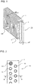
- FIG. 1 is a perspective view showing a heat exchanger 10 according to Embodiment 1 of the present invention.
- FIG. 2 is a cross-sectional view taken along a line A-A in FIG. 1 , showing a fin core 14 of the heat exchanger 10 according to Embodiment 1 of the present invention.
- FIG. 3 is a cross-sectional view taken along a line B-B in FIG. 2 , showing a conduit line 13 of the heat exchanger 10 according to Embodiment 1 of the present invention.
- FIG. 4 is an enlarged perspective view showing a fin collar 11 of the heat exchanger 10 according to Embodiment 1 of the present invention.
- FIG. 5 is a top plan view showing the fin collar 11 of the heat exchanger 10 according to Embodiment 1 of the present invention.
- ig. 6 is a schematic diagram showing a relationship between a thickness of a resin layer in the conduit line 13, and performance and mechanical strength of the heat exchanger 10 according to Embodiment 1 of the present invention.
- Some of the plurality of conduit lines 13 include a resin structure 15, exemplifying the reinforcing member, inserted in the conduit line 13 and fastened to the end portions of the fin core 14 with a resin material.
- the resin structure 15 has a cross section in a cross shape formed to contact the inner wall of the conduit line 13 at every 90 degrees, and extends throughout the conduit line 13 from one end to the other.
- the resin structure 15 has a length corresponding to the length of the conduit line 13 from one end to the other, and serves to improve the rigidity of the conduit line 13.
- the refrigerant flows in the same way as in the heating operation, except that the refrigerant flowing in the conduit lines 13 of the heat exchanger 10, assuming the form of cold water, cools the air.
- the process of covering with the resin the surface of the inner wall of the conduit line 13, formed of the fin collars 11, and the process of inserting and fixing the resin structure 15 in the conduit line 13 may be performed in a reversed order, provided that the resin structure 15 is not affected by the heating temperature required for fluidizing the resin.
- some of the conduit lines 13 include the metal structure 61 serving as the reinforcing member, and therefore the rigidity of the heat exchanger 10 is increased. Accordingly, the strength of the joint portion against a bending, twisting, or shearing force, applied when the heat exchanger 10 is installed in the casing or transported, can be improved.
- the metal structure 61 contributes to increasing the heat transfer area between the refrigerant and air, to thereby improve the heat exchange efficiency.
- the metal pipe 71 is inserted and fixed in some of the plurality of conduit lines 13, together with the side plate 81.
- the side plate 81 is fixed at the same time that the plurality of metal pipes 71 are fixed.
- the plurality of communication members 5 are integrally formed with a reinforcing wall 46, having the same shape as the fin 1 and provided at one end portion of the fin core 14.
- FIG. 30 is a refrigerant circuit diagram showing a general configuration of an air-conditioning apparatus 200 according to Embodiment 11 of the present invention.
- the controller 211 switches the four-way valve 203 to the cooling operation, the refrigerant compressed by the compressor 201 to turn into high-temperature and high-pressure gas refrigerant flows into the outdoor heat exchanger 204 through the four-way valve 203.
- the high-temperature and high-pressure gas refrigerant that has flowed into the outdoor heat exchanger 204 exchanges heat with (radiates heat to) the outside air flowing through the outdoor heat exchanger 204, and flows out in the form of high-pressure liquid refrigerant.
- the conduit lines 13 include the reinforcing member made of a resin, the rigidity of the heat exchanger 10 is increased. Accordingly, the strength of the joint portion against a bending, twisting, or shearing force, applied when the heat exchanger 10 is installed in the casing or transported, can be improved. Further, since the resin is light in weight and inexpensive, both the weight and the cost of the heat exchanger 10 can be reduced.
- the resin layer 12 is formed after the metal structure 61 is inserted and fixed, and hence the resin layer 12 is continuously formed between the inner wall of the conduit line 13 and the surface of the metal structure 61. Therefore, the resin layer 12 is barely likely to be peeled off.
- the reinforcing member is constituted of the metal pipe 71 inserted and fixed in the conduit line 13.
- the reinforcing member is attached to penetrate through the inlet header 2 or outlet header 3, connected to one end portion of the conduit lines 13 in the fin core 14, and the communication member 5 for conducting the refrigerant from one conduit line 13 to another.
- the reinforcing member including the integrally formed communication member 5 provided in some of the conduit lines 13, to the fin core 14 allows the strength required for fastening the fin core 14 with the communication member 5 to be secured, with a fewer number of reinforcing members than the number of liquid paths. Accordingly, the number of joint positions between the reinforcing member and the communication member 5 is reduced, which minimizes the risk of refrigerant leakage. Further, reducing the number of joint positions leads to reduction in manufacturing cost, and reducing the number of liquid pipes that include the reinforcing member contributes to improving the performance of the heat exchanger 10. In addition, employing a resin structural material having a low thermal conductivity than a metal to form the communication member 5 restricts the refrigerant from exchanging heat with the refrigerant flowing in another liquid path, to thereby reduce heat loss.
- the inner wall of the conduit line 13 is covered with the resin layer 12 formed of a thin film, to prevent corrosion of the fin collars 11.
- the conduit line 13 is reinforced with the reinforcing member, to prevent the serially connected fin collars 11 from being mechanically deformed, which contributes to preventing formation of a crack in the resin layer 12.
- the air-conditioning apparatus 200 includes the compressor 201, the outdoor heat exchanger 204, the electronic expansion valve 207, and the indoor heat exchanger, which is the heat exchanger 10.
- the air-conditioning apparatus 200 configured as above includes the reinforcing member, for example the resin structure 15, provided in some of the conduit lines 13 of the heat exchanger 10, and therefore the rigidity of the heat exchanger 10 is increased. Accordingly, the strength of the joint portion between the serially connected fin collars 11, against a bending, twisting, or shearing force applied when the heat exchanger 10 is installed in the casing or transported, can be improved. In addition, there is no need to increase the thickness of the resin layer 12 in the conduit line 13 to increase the strength of the joint portion, and the resin layer 12 can be formed in a thin thickness on the surface of the inner wall of the conduit line 13 formed of the fin collars 11, which prevents degradation in heat exchange performance originating from an increase in thermal resistance of the resin layer 12. Consequently, a high performance level, and reliability in strength and corrosion resistance, can both be secured.
- the reinforcing member for example the resin structure 15, provided in some of the conduit lines 13 of the heat exchanger 10, and therefore the rigidity of the heat exchanger 10 is increased. Accordingly,
Landscapes
- Engineering & Computer Science (AREA)
- Physics & Mathematics (AREA)
- Thermal Sciences (AREA)
- Mechanical Engineering (AREA)
- General Engineering & Computer Science (AREA)
- Geometry (AREA)
- Heat-Exchange Devices With Radiators And Conduit Assemblies (AREA)
- Details Of Heat-Exchange And Heat-Transfer (AREA)
Abstract
Description
- The present invention relates to a plate-fin heat exchanger for use in an air-conditioning apparatus such as a room air-conditioner or a package air-conditioner, and more particularly to a heat exchanger and an air-conditioning apparatus, configured to improve strength of joint portions between a plurality of fins, the fins being serially connected to each other by superposing fin collars of each of the fins.
- Conventional heat exchangers include a plurality of fins, each having a plurality of fin collars, each formed in a short cylindrical shape by perforating a flat base plate. The plurality of fins are stacked on each other, with the fin collars of the fin serially connected to the corresponding fin collars of the adjacent fin. Further, the fin collars adjacent to each other are bonded with a resin to form conduit lines and a fin core, and a resin layer is formed on the inner surface of each of the conduit lines.
- The heat exchanger configured as above allows a fluid passing through the fin core to exchange heat with a fluid passing through the conduit line. In addition, since the inner surface of the conduit line is coated with the resin, the conduit line is sealed, and corrosion of the metal surface of the conduit line can be prevented (see, for example, Patent Literature 1).
- Patent Literature 1: Japanese Examined Patent Application Publication No.
61-015359 - In the conventional heat exchanger, the joint portions between the serially connected fin collars are only fixed with the resin. Therefore, sufficient strength is unable to be secured against a bending, twisting, or shearing force, applied to the joint portion when the heat exchanger is installed in a casing, or transported.
- To improve the strength of the joint portion, the thickness of the resin layer may be increased. However, increasing the thickness of the resin layer leads to increased thermal resistance, and hence to degraded heat exchange performance.
- The present invention has been accomplished in view of the foregoing problem, and provides a heat exchanger that exhibits high performance, and also provides reliability in strength and corrosion resistance, and an air-conditioning apparatus including such a heat exchanger.
- In one embodiment, the present invention provides a heat exchanger including A heat exchanger including a plurality of fins each including a fin collar formed in a short cylindrical shape by perforating a flat base plate, the plurality of fins being stacked by serially connecting fin collars of the respective fins, the serially connected fin collars being bonded to form a conduit line and a fin core, the conduit line including a resin layer formed on an inner surface thereof, the heat exchanger comprising a reinforcing member having a length corresponding to a length of the conduit line from one end to an other end thereof, to improve rigidity of the conduit line.
- Since the heat exchanger of one embodiment of the present invention includes the reinforcing member having a length corresponding to the length of the conduit line from one end to the other end thereof, to improve rigidity of the conduit line, the strength of the joint portion against a bending, twisting, or shearing force, applied when the heat exchanger is installed in a casing or transported, can be improved. In addition, there is no need to increase the thickness of the resin layer to improve the strength, and therefore degradation in heat exchange performance originating from the increased thermal resistance of the resin layer can be prevented. Consequently, a high performance level, and reliability in strength and corrosion resistance, can both be secured.
-
- FIG. 1
- is a perspective view showing a heat exchanger according to
Embodiment 1 of the present invention. - FIG. 2
- is a cross-sectional view taken along a line A-A in
FIG. 1 , showing a fin core of the heat exchanger according toEmbodiment 1 of the present invention. - FIG. 3
- is a cross-sectional view taken along a line B-B in
FIG. 2 , showing a conduit line of the heat exchanger according toEmbodiment 1 of the present invention. - FIG. 4
- is an enlarged perspective view showing a fin collar of the heat exchanger according to
Embodiment 1 of the present invention. - FIG. 5
- is a plan view showing the fin collar of the heat exchanger according to
Embodiment 1 of the present invention. - FIG. 6
- is a schematic diagram showing a relationship between a thickness of a resin layer in the conduit line, and performance and mechanical strength of the heat exchanger according to
Embodiment 1 of the present invention. - FIG. 7
- is a perspective view showing a heat exchanger according to
Embodiment 2 of the present invention. - FIG. 8
- is a cross-sectional view taken along a line A-A in
FIG. 7 , showing a fin core of the heat exchanger according toEmbodiment 2 of the present invention. - FIG. 9
- is a cross-sectional view taken along a line B-B in
FIG. 8 , showing a conduit line of the heat exchanger according toEmbodiment 2 of the present invention. - FIG. 10
- is a view showing an end portion of a fin core of a heat exchanger according to
Embodiment 3 of the present invention. - FIG. 11
- is a cross-sectional view taken along a line B-B in
FIG. 10 , showing a conduit line of the heat exchanger according toEmbodiment 3 of the present invention. - FIG. 12
- is a cross-sectional view showing a fin core of a heat exchanger according to Embodiment 4 of the present invention.
- FIG. 13
- is a cross-sectional view taken along a line B-B in
FIG. 12 , showing a conduit line of the heat exchanger according toEmbodiment 4 of the present invention. - FIG. 14
- is a cross-sectional view showing a fin core of a heat exchanger according to Embodiment 5 of the present invention.
- FIG. 15
- is a cross-sectional view taken along a line B-B in
FIG. 14 , showing a conduit line of the heat exchanger according toEmbodiment 5 of the present invention. - FIG. 16
- is a perspective view showing a heat exchanger according to Embodiment 6 of the present invention.
- FIG. 17
- is a cross-sectional view taken along a line A-A in
FIG. 16 , showing a conduit line of the heat exchanger according to Embodiment 6 of the present invention. - FIG. 18
- is a cross-sectional view showing a fin core of a heat exchanger according to Embodiment 7 of the present invention.
- FIG. 19
- is a cross-sectional view showing another fin core of the heat exchanger according to Embodiment 7 of the present invention.
- FIG. 20
- is a cross-sectional view showing still another fin core of the heat exchanger according to Embodiment 7 of the present invention.
- FIG. 21
- is a perspective view showing a heat exchanger according to Embodiment 8 of the present invention.
- FIG. 22
- is another perspective view showing the heat exchanger according to Embodiment 8 of the present invention.
- FIG. 23
- is a cross-sectional view taken along a line A-A in
FIG. 21 , showing a conduit line of the heat exchanger according to Embodiment 8 of the present invention. - FIG. 24
- is a perspective view showing a heat exchanger according to Embodiment 9 of the present invention.
- FIG. 25
- is another perspective view showing the heat exchanger according to Embodiment 9 of the present invention.
- FIG. 26
- is a cross-sectional view taken along a line A-A in
FIG. 24 , showing a conduit line of the heat exchanger according to Embodiment 9 of the present invention. - FIG. 27
- is a perspective view showing a heat exchanger according to
Embodiment 10 of the present invention. - FIG. 28
- is another perspective view showing the heat exchanger according to
Embodiment 10 of the present invention. - FIG. 29
- is a cross-sectional view taken along a line A-A in
FIG. 27 , showing a conduit line of the heat exchanger according toEmbodiment 10 of the present invention. - FIG. 30
- is a refrigerant circuit diagram showing a general configuration of an air-conditioning apparatus according to
Embodiment 11 of the present invention. - Hereinafter, Embodiments of a heat exchanger according to the present invention will be described.
- The shapes of elements expressed in the drawings are merely exemplary, and not intended to limit the present invention. In all the drawings, the elements of the same reference sign represent the same or corresponding ones, which applies throughout the description. Further, in all the drawings, the dimensional relationship among the elements may differ from the actual ones.
-
FIG. 1 is a perspective view showing aheat exchanger 10 according toEmbodiment 1 of the present invention.FIG. 2 is a cross-sectional view taken along a line A-A inFIG. 1 , showing afin core 14 of theheat exchanger 10 according toEmbodiment 1 of the present invention.FIG. 3 is a cross-sectional view taken along a line B-B inFIG. 2 , showing aconduit line 13 of theheat exchanger 10 according toEmbodiment 1 of the present invention.FIG. 4 is an enlarged perspective view showing afin collar 11 of theheat exchanger 10 according toEmbodiment 1 of the present invention.FIG. 5 is a top plan view showing thefin collar 11 of theheat exchanger 10 according toEmbodiment 1 of the present invention. ig. 6 is a schematic diagram showing a relationship between a thickness of a resin layer in theconduit line 13, and performance and mechanical strength of theheat exchanger 10 according toEmbodiment 1 of the present invention. - In the drawings, a blank arrow denoted by WF indicates an airflow direction, and a blank arrow denoted by RF indicates a refrigerant flow direction.
- As shown in
FIG. 1 to FIG. 6 , theheat exchanger 10 according toEmbodiment 1 includes a plurality offins 1, each including a plurality offin collars 11 formed in a short cylindrical shape by perforating a flat base plate. - The
fins 1 are serially connected to each other, by superposing thefin collars 11 on the corresponding ones of theadjacent fin 1. The serially connectedfin collars 11 are bonded to the adjacent ones with a resin to form a plurality ofconduit lines 13 and thefin core 14 along which air flows, and aresin layer 12 is formed to cover the inner surface of theconduit line 13. - Although the conduit lines 13 formed as above have a cylindrical shape as shown in
FIG. 2 , the shape of the conduit lines 13 is not specifically limited, and not limited to a symmetrical shape. - The conduit lines 13 each include a
joint pipe 4 connected to the respective end portions, at the terminal one of thefins 1 stacked on each other. The conduit lines 13 are aligned in a plurality of rows, for example in two rows as shown inFIG. 1 , in a direction orthogonal to the stacking direction of thefins 1, in other words in the airflow direction (WF), or row direction, and aligned in a plurality of columns, for example in eight columns as shown inFIG. 1 , in a direction orthogonal to the row direction, in other words in the column direction. - Out of the plurality of
conduit lines 13 aligned in the row direction, the plurality ofconduit lines 13 located on the leeward side are each connected to aninlet header 2, at an end portion. The plurality ofconduit line 13 located on the windward side are each connected to anoutlet header 3, at an end portion. The leeward section and the windward section of each of the plurality ofconduit lines 13 are communicably connected to each other at the non-illustrated other end portion, for example via a U-pipe. - Some of the plurality of
conduit lines 13 include aresin structure 15, exemplifying the reinforcing member, inserted in theconduit line 13 and fastened to the end portions of thefin core 14 with a resin material. - The
resin structure 15 has a cross section in a cross shape formed to contact the inner wall of theconduit line 13 at every 90 degrees, and extends throughout theconduit line 13 from one end to the other. Thus, theresin structure 15 has a length corresponding to the length of theconduit line 13 from one end to the other, and serves to improve the rigidity of theconduit line 13. - The
resin structure 15 exemplifying the reinforcing member corresponds to the resin structural material provided inside theconduit line 13. - As shown in
FIG. 3 , thefin collar 11 is formed in a tapered shape, such that distal end portion in the stacking direction is smaller in diameter than the base portion. - As shown in
FIG. 4 andFIG. 5 , thefin collar 11 includes acylindrical portion 21 and atop portion 22. Thefin collars 11 are serially connected to each other, with thetop portion 22 inserted into thecylindrical portion 21 of theadjacent fin collar 11. Serially connecting thus thefin collars 11 constitutes the stacked structure of thefins 1. - An operation of the
heat exchanger 10 according toEmbodiment 1 will be described hereunder, referring to the case where theheat exchanger 10 is incorporated in an indoor unit of an air-conditioning apparatus in which the heat exchange is performed between refrigerant and air. - As indicated by the airflow direction (WF) in
FIG. 1 , the air is introduced into theheat exchanger 10, for example by a fan, flows along thefin core 14, more specifically through the gap defined between thefins 1 adjacent to each other, and flows out from theheat exchanger 10 after exchanging heat with the refrigerant, such as water, flowing in theconduit line 13. - The refrigerant flows as follows. In a heating operation, the refrigerant flowing in the conduit lines 13 of the
heat exchanger 10, assuming the form of hot water, heats the air. The hot water flows into theheat exchanger 10 from theinlet header 2, flows through the leeward section of theconduit line 13 in the stacking direction of thefins 1, passes through the U-pipe and flows through the windward section of theconduit line 13, and flows out from theheat exchanger 10 after being merged in theoutlet header 3. The hot water is subjected to the heat exchange in what is known as a pseudo-counterflow method. - In a cooling operation, the refrigerant flows in the same way as in the heating operation, except that the refrigerant flowing in the conduit lines 13 of the
heat exchanger 10, assuming the form of cold water, cools the air. - Referring to
FIG. 2 andFIG. 3 , a manufacturing method of theheat exchanger 10 according toEmbodiment 1 will be described hereunder. - The
fins 1, each including a plurality offin collars 11 formed in a tapered cylindrical shape, for example by pressing, are serially connected by superposing thefin collars 11 as shown inFIG. 3 . - A resin is injected into inside of the
cylindrical portions 21 of therespective fins 1, from the terminal one of thefins 1 connected as above, and then theinlet header 2, theoutlet header 3, and thejoint pipes 4 are attached. - To form the
resin layer 12 inside thefin collars 11, precoated fins to which a resin is applied in advance may be employed. Then, the resin is heated and fluidized to cover the surface of the inner wall of theconduit line 13, formed of thefin collars 11, with the resin. The resin is also led to permeate into the joint portions between thefin collars 11 adjacent to each other, to bond thefin collars 11 together, and then cooled and solidified to fix thefin collars 11. - In this process, the type of the resin, as well as the temperature and the time for heating and cooling are properly selected, and the
resin layer 12 is formed over the surface of the inner wall of theconduit line 13 in a thin thickness, preferably equal to or less than 50 µm. - Then, the
resin structure 15 shown inFIG. 2 , serving as the reinforcing member, is inserted in each of the conduit lines 13 of predetermined positions. Since theresin structure 15 inserted in theconduit line 13 has a length corresponding to the length of theconduit line 13 from one end to the other, theresin structure 15 can be easily fastened to the end portions of thefin core 14 with a resin material, and thus the manufacturing process can be simplified. Providing theresin structure 15 in as many number ofconduit lines 13 as possible leads to improved strength of theheat exchanger 10. However, it is preferable, from the viewpoint of cost, to provide theresin structure 15 in a minimum possible number of conduit lines 13. - Although the
resin structure 15 has a cross section in a cross shape as shown inFIG. 2 , the shape of theresin structure 15 is not specifically limited, and not limited to a symmetrical shape. In addition, the material of theresin structure 15 serving as the reinforcing member is not limited to resins but may be a metal, provided that the metal has sufficient corrosion resistance. - However, it is preferable to employ a resin to form the reinforcing member, because the
resin layer 12 is unlikely to be peeled off owing to friction with the reinforcing member. - The process of covering with the resin the surface of the inner wall of the
conduit line 13, formed of thefin collars 11, and the process of inserting and fixing theresin structure 15 in theconduit line 13 may be performed in a reversed order, provided that theresin structure 15 is not affected by the heating temperature required for fluidizing the resin. - In particular, in the case where the reinforcing member is formed of a metal, the
resin layer 12 may be peeled off owing to friction with the reinforcing member. Accordingly, it is preferable to form theresin layer 12 after inserting the reinforcing member. In the case where theresin layer 12 is formed after the reinforcing member is inserted, at least a portion of the surface of the reinforcing member, in particular a portion abutted to the inner wall of theconduit line 13, is covered with theresin layer 12, and hence theresin layer 12 can be prevented from being peeled off. In the case where the reinforcing member is formed of a resin also, forming theresin layer 12 after inserting the reinforcing member prevents the resin layer from being peeled off. Thus, at least a part of the reinforcing member may be covered with thesame resin layer 12 covering the inner surface of theconduit line 13. - As described above, the
heat exchanger 10 according toEmbodiment 1 includes theresin structure 15, having the length corresponding to the length of theconduit line 13 from one end to the other and provided in some of the conduit lines 13, to improve the rigidity of theconduit line 13. Accordingly, the rigidity of theheat exchanger 10 is increased, and the strength of the joint portion between the serially connectedfin collars 11, against a bending, twisting, or shearing force applied when theheat exchanger 10 is installed in the casing or transported, can be improved. In addition, there is no need to increase the thickness of theresin layer 12 in theconduit line 13 to increase the strength of the joint portion, and theresin layer 12 can be formed in a thin thickness on the surface of the inner wall of theconduit line 13 formed of thefin collars 11, which prevents degradation in heat exchange performance originating from an increase in thermal resistance of theresin layer 12. Consequently, a high performance level, and reliability in strength and corrosion resistance, can both be secured. - Here, the number of
conduit lines 13 aligned in the row direction and the column direction may be determined as desired, without limitation to the example inEmbodiment 1. In addition, the heat exchange between air and the refrigerant may be performed in a pseudo-parallel flow method by inverting the airflow direction, instead of in the pseudo-counterflow method. Further, theconduit line 13 including theresin structure 15 inserted therein may be, or may not be, utilized for the heat exchange by supplying the refrigerant. In other words, theresin structure 15 may be provided only in some ofconduit lines 13 through which the refrigerant flows, out of the plurality of conduit lines 13. - In
Embodiment 2, theconduit line 13 is filled with a resin that constitutes the reinforcing member. The items not specifically referred to inEmbodiment 2 are the same as those ofEmbodiment 1. -
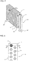
FIG. 7 is a perspective view showing aheat exchanger 10 according toEmbodiment 2 of the present invention.FIG. 8 is a cross-sectional view taken along a line A-A inFIG. 7 , showing afin core 14 of theheat exchanger 10 according toEmbodiment 2 of the present invention.FIG. 9 is a cross-sectional view taken along a line B-B inFIG. 8 , showing aconduit line 13 of theheat exchanger 10 according toEmbodiment 2 of the present invention. - As shown in
FIG. 7 to FIG. 9 , theheat exchanger 10 according toEmbodiment 2 includes a resin-filledportion 31 that serves as the reinforcing member, provided in some of the plurality of conduit lines 13. - As shown in
FIG. 8 , the inside of some of the plurality ofconduit lines 13, formed through thefins 1 serially connected in the stacking direction, is filled with a resin adhesive to form the resin-filledportion 31. - To form the resin-filled
portion 31, processing for preventing leakage of the resin is performed on the terminal one of thestacked fins 1, through which the conduit lines 13 are formed, and which are serially connected by superposing the plurality offin collars 11, formed on each of thefins 1 in a tapered cylindrical shape for example by pressing, and then the resin is injected into theconduit line 13 from the terminal one of thestacked fins 1 on the other side. The resin-filledportion 31 is formed by filling the entire inner space of theconduit line 13 from one end to the other, with the resin. The resin-filledportion 31 is not utilized for the heat exchange unlike theresin structure 15 ofEmbodiment 1, and therefore it is not necessary to connect the inlet header, the outlet header, and the connection pipes to the resin-filledportion 31. - In addition, the resin-filled
portion 31 serves to reinforce some of the conduit lines 13 through which the refrigerant does not flow, and therefore theresin layer 12 formed in the remaining conduit lines 13, through which the refrigerant flows, is free from the risk of being peeled off owing to the presence of the resin-filledportion 31. - As described above, in the
heat exchanger 10 according toEmbodiment 2, some of the plurality ofconduit lines 13 are filled with the resin and serve as the reinforcing member, and hence the rigidity of theheat exchanger 10 is increased. Therefore, the strength of the joint portion against a bending, twisting, or shearing force, applied when theheat exchanger 10 is installed in the casing or transported, can be improved. Further, since the resin is light in weight and inexpensive, both the weight and the cost of theheat exchanger 10 can be reduced, compared with the case of employing a reinforcing member made of a metal. - In
Embodiment 3, theconduit line 13 includesfin fasteners support rod 42, which serve as the reinforcing member. The items not specifically referred to inEmbodiment 3 are the same as those ofEmbodiment 1. -
FIG. 10 is a view showing an end portion of afin core 14 of aheat exchanger 10 according toEmbodiment 3 of the present invention.FIG. 11 is a cross-sectional view taken along a line B-B inFIG. 10 , showing aconduit line 13 of theheat exchanger 10 according toEmbodiment 3 of the present invention. - As shown in
FIG. 10 andFIG. 11 , thesupport rod 42 is provided throughout the inside of some of the plurality ofconduit lines 13 serially connected in the stacking direction. Thefin fasteners support rod 42 fasten thefin core 14, from the both end faces thereof. Thefin fastener 41 has a cross shape, and is engaged with the opening of thefin collar 11 of the terminal one of thestacked fins 1. Thefin fastener 43 covers thefin collar 11 sticking out from the terminal one of thestacked fins 1 on the other side. Thesupport rod 42 is connected to thefin fasteners fin fasteners conduit line 13 improves the rigidity thereof against a force exerted in a direction to stretch theconduit line 13. In addition, thesupport rod 42 is retained with a spacing from the inner wall of theconduit line 13, when thefin fasteners fin fasteners support rod 42 reinforce the entirety of theconduit line 13, from one end to the other. - Here, either a resin or a metal may be employed to form the
fin fasteners support rod 42, provided that the rigidity required for fastening thefin core 14 can be attained. However, it is preferable to employ a resin, in the case where thefin fasteners fin 1 covered with theresin layer 12. Thefin fasteners resin layer 12, like theconduit line 13. Further, at least one of thefin fasteners support rod 42 may be formed of an elastic material to apply a biasing force in a direction to compress theconduit line 13. - As described above, the
heat exchanger 10 according toEmbodiment 3 includes the reinforcing member composed of thefin fasteners support rod 42, and provided in some of the conduit lines 13. Therefore, the rigidity of theheat exchanger 10 is increased, and the strength of the joint portion against a bending, twisting, or shearing force, applied when theheat exchanger 10 is installed in the casing or transported, can be improved. - Further, since the
support rod 42 is retained with a spacing from the inner wall of theconduit line 13, thesupport rod 42 is kept from contacting theresin layer 12 on the inner wall of theconduit line 13, and thus theresin layer 12 is prevented from being peeled off. - In
Embodiment 4, theconduit line 13 includes ametal structure 61 that serves as the reinforcing member. The items not specifically referred to inEmbodiment 4 are the same as those ofEmbodiment 1. -
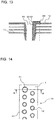
FIG. 12 is a cross-sectional view showing afin core 14 of aheat exchanger 10 according toEmbodiment 4 of the present invention.FIG. 13 is a cross-sectional view taken along a line B-B inFIG. 12 , showing aconduit line 13 of theheat exchanger 10 according toEmbodiment 4 of the present invention. - As shown in
FIG. 12 andFIG. 13 , some of the plurality ofconduit lines 13 include themetal structure 61 of a plate shape, fitted to aslit 62 formed through thefins 1 and thefin collars 11. The plate-shapedmetal structure 61 is fitted to thefins 1 and thefin collars 11, throughout the entirety of theconduit line 13, from one end to the other. Themetal structure 61 is fitted to theslit 62 formed through thefins 1 and thefin collars 11, with an edge sticking out into the inner space of theconduit line 13. - The
metal structure 61 fitted to thefins 1 and thefin collars 11 is covered with the resin, through the process of forming theresin layer 12 inside theconduit line 13. - Here, the
metal structure 61 does not necessarily have to have a plate shape, provided that theedge 63 sticks out into the inner space of theconduit line 13, and may be fitted to theconduit line 13 at a plurality of positions. - In
Embodiment 4, since themetal structure 61 has to be covered with the resin through the process of forming theresin layer 12, themetal structure 61 is fitted to thefins 1 and thefin collars 11, before theresin layer 12 is formed. - As described above, in the
heat exchanger 10 according toEmbodiment 4, some of the conduit lines 13 include themetal structure 61 serving as the reinforcing member, and therefore the rigidity of theheat exchanger 10 is increased. Accordingly, the strength of the joint portion against a bending, twisting, or shearing force, applied when theheat exchanger 10 is installed in the casing or transported, can be improved. In addition, themetal structure 61 contributes to increasing the heat transfer area between the refrigerant and air, to thereby improve the heat exchange efficiency. - Further, since the
resin layer 12 is formed after themetal structure 61 is inserted and fixed, theresin layer 12 is continuously formed between the inner wall of theconduit line 13 and the surface of themetal structure 61. Therefore, theresin layer 12 is barely likely to be peeled off. - In
Embodiment 5, theconduit line 13 includes ametal pipe 71 that serves as the reinforcing member. The items not specifically referred to inEmbodiment 5 are the same as those ofEmbodiment 1. -
FIG. 14 is a cross-sectional view showing afin core 14 of aheat exchanger 10 according toEmbodiment 5 of the present invention.FIG. 15 is a cross-sectional view taken along a line B-B inFIG. 14 , showing aconduit line 13 of theheat exchanger 10 according toEmbodiment 5 of the present invention. - As shown in
FIG. 14 andFIG. 15 , themetal pipe 71 is inserted and fixed in some of the plurality of conduit lines 13. Themetal pipe 71 is inserted in theconduit line 13 as shown inFIG. 14 , and the diameter of themetal pipe 71 is enlarged by an expanding billet to swage themetal pipe 71 with thefin collars 11, thus to fix themetal pipe 71. - In the
heat exchanger 10 according toEmbodiment 5, some of the conduit lines 13 include themetal pipe 71 serving as the reinforcing member, and therefore the rigidity of theheat exchanger 10 is increased. Accordingly, the strength of the joint portion against a bending, twisting, or shearing force, applied when theheat exchanger 10 is installed in the casing or transported, can be improved. In addition, the machine for enlarging the diameter of themetal pipe 71 is popularly available in the manufacturing equipment of theheat exchanger 10, and therefore the existing equipment can be utilized as it is, to manufacture theaforementioned heat exchanger 10. - Since the plurality of
conduit lines 13 continuously extend through thefins 1, reinforcing some of the conduit lines 13 by inserting themetal pipe 71 results in substantially reinforcing the remaining conduit lines 13 in each of which themetal pipe 71 is not provided. Reinforcing the plurality of conduit lines 13 prevents theresin layer 12 on the inner surface of the conduit lines 13 without themetal pipe 71, from being peeled off. - In Embodiment 6, the
conduit line 13 includes themetal pipe 71 and aside plate 81 that serve as the reinforcing member. The items not specifically referred to in Embodiment 6 are the same as those ofEmbodiment 1 andEmbodiment 5. -
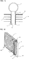
FIG. 16 is a perspective view showing aheat exchanger 10 according to Embodiment 6 of the present invention.FIG. 17 is a cross-sectional view taken along a line A-A inFIG. 16 , showing aconduit line 13 of theheat exchanger 10 according to Embodiment 6 of the present invention. - As shown in
FIG. 16 andFIG. 17 , themetal pipe 71 is inserted and fixed in some of the plurality ofconduit lines 13, together with theside plate 81. Referring toFIG. 17 , theside plate 81 is fixed at the same time that the plurality ofmetal pipes 71 are fixed. - In the
heat exchanger 10 according to Embodiment 6, theside plate 81 is attached, in addition to themetal pipe 71 provided in some of the conduit lines 13 as the reinforcing member. Therefore, the rigidity of theheat exchanger 10 is increased both in the stacking direction and in the horizontal direction. Consequently, the strength of the joint portion against a bending, twisting, or shearing force, applied when theheat exchanger 10 is installed in the casing or transported, can be significantly improved. -
Embodiment 7 refers to the pipe diameter, the position, and the number of the conduit lines 13 that include the reinforcing member. The items not specifically referred to inEmbodiment 7 are the same as those ofEmbodiments 1 to 6. -
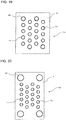
FIG. 18 is a cross-sectional view showing afin core 14 of aheat exchanger 10 according toEmbodiment 7 of the present invention.FIG. 19 is a cross-sectional view showing anotherfin core 14 of theheat exchanger 10 according toEmbodiment 7 of the present invention.FIG. 20 is a cross-sectional view showing still anotherfin core 14 of theheat exchanger 10 according toEmbodiment 7 of the present invention. - As shown in
FIG. 18 to FIG. 20 , the pipe diameter of aconduit line 91 that includes the reinforcing member may differ from the pipe diameter of the conduit lines 13 including theresin layer 12 and utilized for the heat exchange. From the viewpoint of improvement in performance and reduction in cost of theheat exchanger 10 in particular, it is preferable to make theconduit line 91 including the reinforcing member larger than the conduit lines 13 for the refrigerant, to both reduce the diameter of the conduit lines 13 and minimize the number ofconduit lines 91 including the reinforcing member. - As shown in
FIG. 18 to FIG. 20 , theconduit line 91 including the reinforcing member is located at a position closest to the outer periphery of thefin 1. In particular, in the case where an even number ofconduit lines 91 including the reinforcing member are provided, it is preferable to locate the conduit lines 91 to be symmetrical. - The conduit lines 13 in the
fins 1 are arranged in a predetermined pattern. However, the conduit lines 91 including the reinforcing member do not have to follow the arrangement pattern of the conduit lines 13. It is preferable to locate the conduit lines 91 to maximize the rigidity of theheat exchanger 10, for example at the four corners of thefin 1 as shown inFIG. 20 . - In the
heat exchanger 10 according toEmbodiment 7, the pipe diameter, the position, and the number of the conduit lines 91 that include the reinforcing member, are determined to maximize the rigidity of theheat exchanger 10, and therefore the strength of the joint portion against a bending, twisting, or shearing force, applied when theheat exchanger 10 is installed in the casing or transported, can be improved. - Embodiment 8 refers to the method of fastening the reinforcing member to the
fin core 14. The items not specifically referred to in Embodiment 8 are the same as those ofEmbodiments 1 to 7, and the same functions and components are denoted by the same reference sign. -
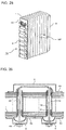
FIG. 21 is a perspective view showing aheat exchanger 10 according to Embodiment 8 of the present invention.FIG. 22 is another perspective view showing theheat exchanger 10 according to Embodiment 8 of the present invention.FIG. 23 is a cross-sectional view taken along a line A-A inFIG. 21 , showing aconduit line 13 of theheat exchanger 10 according to Embodiment 8 of the present invention. - As shown in
FIG. 21 to FIG. 23 , the reinforcing member fastens theconduit line 13, with aheader fastener 44 attached to each of theinlet header 2 and theoutlet header 3 located at the end portions of thefin core 14, acommunication member fastener 45 attached to at least one side of acommunication member 5, such as a U-bend pipe, for turning the direction of the refrigerant that has passed through theconduit line 13 and conducting the refrigerant to anotherconduit line 13, and anelongate support rod 42 penetrating through theconduit line 13 from one end to the other and being connected to theheader fastener 44 and thecommunication member fastener 45. - The
communication member 5 may be formed in one integral piece to constitute a turning path, provided that thecommunication member 5 is connected to the end portion of thefin core 14 and communicates between two conduit lines 13. Alternatively, thecommunication member 5 may form the turning path by attaching a member having a concave surface to thefin core 14, and establishing communication between the outlets of two conduit lines 13. - The
communication member 5 may be formed of either a metal or a resin, provided that the joint strength to thefin core 14 and corrosion resistance against moisture can be secured. Theheader fastener 44, thecommunication member fastener 45, and thesupport rod 42 may be formed of either a metal or a resin, provided that the rigidity required for fastening thefin core 14 is attained. - The joint portion between the
communication member 5 and thefin core 14, and a gap in the reinforcing member passway of thecommunication member 5 may be covered with thecommunication member fastener 45. Further, the reinforcing member may be inserted and fixed before the surface of thefin collar 11 on the side of the liquid passage is covered with the resin, and then the joint portion between thecommunication member 5 and thefin core 14, and the gap in the reinforcing member passway of thecommunication member 5 may be filled with the resin. - In addition, the reinforcing member does not have to have the shape of the support rod shown in
FIG. 23 , but may be formed in any of the shapes of the reinforcing member according toEmbodiments 1 to 7, provided that the reinforcing member is connected to theinlet header 2 oroutlet header 3, and to thecommunication member 5. In particular, in the case of employing the reinforcing member according toEmbodiment 2, thecommunication member 5 may be formed to communicate between at least twoother conduit lines 13, through which the refrigerant flows. - In the
heat exchanger 10 according to Embodiment 8, since the plurality ofconduit lines 13 are constituted of thestacked fins 1, fastening thefins 1 in the stacking direction with theinlet header 2 oroutlet header 3 and thecommunication member 5, which are provided at the end portions of thefins 1, results in substantially reinforcing the conduit lines 13. In addition, reinforcing thecommunication member 5 contributes to improving the joint strength against a stress imposed outwardly of thecommunication member 5, originating from the turning of the refrigerant flow in the liquid passage in thecommunication member 5. Further, the joint portions between thefin core 14 and theinlet header 2 oroutlet header 3, and between thefin core 14 and thecommunication member 5, are also reinforced, and therefore the strength against a bending, twisting, or shearing force, applied when theheat exchanger 10 is installed in the casing or transported, can be improved. - Embodiment 9 refers to the shape of the reinforcing member according to Embodiment 8. The items not specifically referred to in Embodiment 9 are the same as those of Embodiment 8, and the same functions and components are denoted by the same reference sign.
-
FIG. 24 is a perspective view showing aheat exchanger 10 according to Embodiment 9 of the present invention.FIG. 25 is another perspective view showing theheat exchanger 10 according to Embodiment 9 of the present invention.FIG. 26 is a cross-sectional view taken along a line A-A inFIG. 24 , showing aconduit line 13 of theheat exchanger 10 according to Embodiment 9 of the present invention. - As shown in
FIG. 24 to FIG. 26 , thesupport rod 42 is integrally formed with thecommunication member 5 provided at one end portion of thefin core 14, and is connected to theinlet header 2 oroutlet header 3 provided at the other end portion, through the liquid pipe, which is theconduit line 13. - The plurality of
communication members 5 are integrally formed with a reinforcingwall 46, having the same shape as thefin 1 and provided at one end portion of thefin core 14. - A
header fastener 44 is attached to each of theinlet header 2 and theoutlet header 3. Theinlet header 2 and theoutlet header 3 are formed in a rectangular column shape for reinforcement purpose, are abutted against the other end portion of thefin core 14 via plate-shapedportions wall 46 on the side of the plurality ofcommunication members 5. The plate-shapedportions fin 1, from theinlet header 2 and theoutlet header 3 formed in the rectangular column shape. Thus, theheat exchanger 10 according to Embodiment 9 is without thejoint pipes 4. - In the
heat exchanger 10 according to Embodiment 9, the plurality ofcommunication members 5 are integrally formed with the reinforcingwall 46. Accordingly, reinforcing some of thecommunication members 5 results in substantially reinforcing theother communication members 5 that do not have thesupport rod 42. Forming the plurality ofcommunication members 5 integrally with the reinforcingwall 46 enables reduction of the number of joint positions of thecommunication members 5, to thereby minimize the risk of refrigerant leakage. In addition, the number of parts, such as the communication member fasteners, can also be reduced, and therefore both the weight and the manufacturing cost can be reduced. -
Embodiment 10 refers to the shape of the communication member according to Embodiment 8. The items not specifically referred to inEmbodiment 11 are the same as those of Embodiment 8, and the same functions and components are denoted by the same reference sign. -
FIG. 27 is a perspective view showing aheat exchanger 10 according toEmbodiment 10 of the present invention.FIG. 28 is another perspective view showing theheat exchanger 10 according toEmbodiment 10 of the present invention.FIG. 29 is a cross-sectional view taken along a line A-A inFIG. 27 , showing aconduit line 13 of theheat exchanger 10 according toEmbodiment 10 of the present invention. - As shown in
FIG. 27 to FIG. 29 , thecommunication member 5 is formed in one integral piece and connects the plurality ofconduit lines 13 in thefin core 14. Some of the conduit lines 13 in thefin core 14 are fastened with a reinforcing member passed through theconduit line 13. The inner space of thecommunication member 5 is divided by apartition 5a in a U-pipe shape, to conduct the refrigerant that has passed through theconduit line 13 to anotherconduit line 13. Thus, thecommunication member 5 includes a plurality of liquid paths, separated from each other by thepartition 5a and formed in the U-pipe shape. Thecommunication member 5 also constitutes a part of the reinforcing member. - In addition, the
heat exchanger 10 includes aheader unit 47 formed in one integral piece to serve as the reinforcing member, in place of the inlet header and the outlet header. Theheader unit 47 is fixed to a reinforcingwall 48 attached to the other end portion of thefin core 14 and secures balance with the fastening force of the reinforcingwall 46. The inner space of theheader unit 47 is divided by apartition 47a to form two parallel paths in the vertical direction, and thus each of the paths serves as the inlet header or outlet header. - Further, the
heat exchanger 10 includes theheader fastener 44, thecommunication member fastener 45, and thesupport rod 42, which are also the components of the reinforcing member. - In the
heat exchanger 10 according toEmbodiment 10, thecommunication member 5 formed in one integral piece includes the plurality of liquid paths separated from each other, and is fixed to thefin core 14 with thesupport rod 42, provided in some of the liquid paths and inserted in thecorresponding conduit line 13 in thefin core 14. Theheat exchanger 10 also includes theheader unit 47 formed in one integral piece to serve as the inlet header and the outlet header. Therefore, the strength required for fastening thefin core 14 with thecommunication member 5 and theheader unit 47 can be secured, with a fewer number of reinforcing members than the number of liquid paths. Accordingly, the number of joint positions between thesupport rod 42 and thecommunication member 5 or theheader unit 47 is reduced, which minimizes the risk of refrigerant leakage. Further, reducing the number of joint positions leads to reduction in manufacturing cost, and reducing the number of liquid pipes that include the reinforcing member contributes to improving the performance of theheat exchanger 10. - Here, employing a resin structural material having a low thermal conductivity than a metal to form the
communication member 5 or theheader unit 47 restricts the refrigerant from exchanging heat with the refrigerant flowing in another liquid path, to thereby reduce heat loss. -
FIG. 30 is a refrigerant circuit diagram showing a general configuration of an air-conditioning apparatus 200 according toEmbodiment 11 of the present invention. - As shown in
FIG. 30 , the air-conditioning apparatus 200 includes a refrigerant circuit composed of acompressor 201, amuffler 202, a four-way valve 203, anoutdoor heat exchanger 204,capillary tubes 205, astrainer 206, anelectronic expansion valve 207,stop valves heat exchanger 10 serving as an indoor heat exchanger, and anauxiliary muffler 209, which are connected via arefrigerant pipe 210. - The indoor unit of the air-
conditioning apparatus 200, including theheat exchanger 10, includes acontroller 211 that controls the actuators such as thecompressor 201 and theelectronic expansion valve 207, on the basis of the temperature of outside air, room air, and the refrigerant. The four-way valve 203 serves to switch the refrigeration cycle between the cooling operation and the heating operation, under the control of thecontroller 211. - Referring now to
FIG. 30 , an example of the operation of the air-conditioning apparatus 200 performed for cooling will be described. When thecontroller 211 switches the four-way valve 203 to the cooling operation, the refrigerant compressed by thecompressor 201 to turn into high-temperature and high-pressure gas refrigerant flows into theoutdoor heat exchanger 204 through the four-way valve 203. The high-temperature and high-pressure gas refrigerant that has flowed into theoutdoor heat exchanger 204 exchanges heat with (radiates heat to) the outside air flowing through theoutdoor heat exchanger 204, and flows out in the form of high-pressure liquid refrigerant. The high-pressure liquid refrigerant that has flowed out from theoutdoor heat exchanger 204 is depressurized in thecapillary tubes 205 and theelectronic expansion valve 207, thus to turn into low-pressure, two-phase gas-liquid refrigerant, and flows into the indoor heat exchanger, which is theheat exchanger 10. The two-phase gas-liquid refrigerant that has flowed into theheat exchanger 10 exchanges heat with the room air flowing through theheat exchanger 10, thus to cool the room air and turn into low-temperature and low-pressure gas refrigerant, and is sucked into thecompressor 201. - Referring again to
FIG. 30 , an example of the operation of the air-conditioning apparatus 200 performed for heating will be described. When thecontroller 211 switches the four-way valve 203 to the heating operation, the refrigerant, compressed by thecompressor 201 to turn into high-temperature and high-pressure gas refrigerant as above, flows into the indoor heat exchanger, which is theheat exchanger 10, through the four-way valve 203. The high-temperature and high-pressure gas refrigerant that has flowed into theheat exchanger 10 exchanges heat with the room air flowing through theheat exchanger 10, to heat the room air and turn into high-pressure liquid refrigerant. The high-pressure liquid refrigerant that has flowed out from theheat exchanger 10 is depressurized in theelectronic expansion valve 207 and thecapillary tubes 205, thus to turn into low-pressure, two-phase gas-liquid refrigerant, and flows into theoutdoor heat exchanger 204. The low-pressure two-phase gas-liquid refrigerant that has flowed into theoutdoor heat exchanger 204 exchanges heat with the outside air flowing through theoutdoor heat exchanger 204, to turn into low-temperature and low-pressure gas refrigerant, and is sucked into thecompressor 201. - The air-
conditioning apparatus 200 according toEmbodiment 11 includes the reinforcing member, for example theresin structure 15, provided in some of the conduit lines 13 of theheat exchanger 10. Accordingly, the rigidity of theheat exchanger 10 is increased, and the strength of the joint portion between the serially connectedfin collars 11, against a bending, twisting, or shearing force applied when theheat exchanger 10 is installed in the casing or transported, can be improved. In addition, there is no need to increase the thickness of theresin layer 12 in theconduit line 13 to increase the strength of the joint portion, and theresin layer 12 can be formed in a thin thickness on the surface of the inner wall of theconduit line 13 formed of thefin collars 11, which prevents degradation in heat exchange performance originating from an increase in thermal resistance of theresin layer 12. Consequently, a high performance level, and reliability in strength and corrosion resistance, can both be secured. - The
heat exchanger 10 according toEmbodiments 1 to 11 includes the plurality offins 1 each including thefin collars 11 formed in a short cylindrical shape by perforating the flat base plate. The plurality offins 1 are stacked on each other by serially connecting thefin collars 11 of therespective fins 1, and the serially connectedfin collars 11 are bonded to each other to form the conduit lines 13 and thefin core 14. The conduit lines 13 each include theresin layer 12 formed on the inner surface thereof. Theheat exchanger 10 also includes the reinforcing member having the length corresponding to the length of theconduit line 13 from one end to the other end thereof, to improve rigidity of theconduit line 13. - The
heat exchanger 10 configured as above includes the reinforcing member, having the length corresponding to the length of theconduit line 13 from one end to the other, to improve the rigidity of theconduit line 13, and therefore the rigidity of theheat exchanger 10 is increased. Accordingly, the strength of the joint portion against a bending, twisting, or shearing force, applied when theheat exchanger 10 is installed in the casing or transported, can be improved. In addition, there is no need to increase the thickness of theresin layer 12 to increase the strength of the joint portion, and theresin layer 12 can be formed in a thin thickness on the surface of the inner wall of theconduit line 13 formed of thefin collars 11, which prevents degradation in heat exchange performance originating from an increase in thermal resistance of theresin layer 12. Consequently, a high performance level, and reliability in strength and corrosion resistance, can both be secured. - The reinforcing member is provided only in some of
conduit lines 13, out of the plurality of conduit lines 13. - With the mentioned configuration, the rigidity of the
heat exchanger 10 can be increased, by providing the reinforcing member in some ofconduit lines 13 through which the refrigerant flows. - At least a part of the reinforcing member is covered with the
same resin layer 12 covering the inner surface of theconduit line 13. - In this case, since at least a part of the surface of the reinforcing member is covered with the
resin layer 12, theresin layer 12 can be prevented from being peeled off. - The reinforcing member is constituted of the
resin structure 15 located inside theconduit line 13. - In this case, since some of the conduit lines 13 include the reinforcing member made of a resin, the rigidity of the
heat exchanger 10 is increased. Accordingly, the strength of the joint portion against a bending, twisting, or shearing force, applied when theheat exchanger 10 is installed in the casing or transported, can be improved. Further, since the resin is light in weight and inexpensive, both the weight and the cost of theheat exchanger 10 can be reduced. - The reinforcing member is constituted of the resin-filled
portion 31 formed by filling the inner space of at least one of the plurality ofconduit lines 13 with a resin. - With the mentioned configuration, some of the conduit lines 13 filled with the resin serve as the reinforcing member, and hence the rigidity of the
heat exchanger 10 is increased. Accordingly, the strength of the joint portion against a bending, twisting, or shearing force, applied when theheat exchanger 10 is installed in the casing or transported, can be improved. Further, since the resin is light in weight and inexpensive, both the weight and the cost of theheat exchanger 10 can be reduced. - In addition, the resin-filled
portion 31 only reinforces some of the conduit lines 13 through which the refrigerant does not flow, and therefore theresin layer 12 of the remaining conduit lines 13 through which the refrigerant flows is free from the risk of being peeled off owing to the presence of the resin-filledportion 31. - The reinforcing member is configured to fasten the both end faces of the
fin core 14 with thesupport rod 42 passed through theconduit line 13. - In this case, the
support rod 42 is passed through the inside of some of the conduit lines 13, and fastens thefin core 14 from both sides to thereby reinforce thefin core 14. Accordingly, the rigidity of theheat exchanger 10 is increased. Therefore, the strength of the joint portion against a bending, twisting, or shearing force, applied when theheat exchanger 10 is installed in the casing or transported, can be improved. - Further, since the
support rod 42 is retained with a spacing from the inner wall of theconduit line 13, thesupport rod 42 is kept from contacting theresin layer 12 on the inner wall of theconduit line 13, and thus theresin layer 12 is prevented from being peeled off. - The reinforcing member is constituted of the
metal structure 61, fitted in theslit 62 formed in thefin collar 11 and having the edge sticking out into the inner space of theconduit line 13. - With the mentioned configuration, since some of the conduit lines 13 include the
metal structure 61 serving as the reinforcing member, the rigidity of theheat exchanger 10 is increased. Accordingly, the strength of the joint portion against a bending, twisting, or shearing force, applied when theheat exchanger 10 is installed in the casing or transported, can be improved. In addition, themetal structure 61 contributes to increasing the heat transfer area between the refrigerant flowing in theconduit line 13 and air, thus to improve the thermal conduction between the refrigerant and air. Therefore, the heat exchange efficiency can be improved. - Further, the
resin layer 12 is formed after themetal structure 61 is inserted and fixed, and hence theresin layer 12 is continuously formed between the inner wall of theconduit line 13 and the surface of themetal structure 61. Therefore, theresin layer 12 is barely likely to be peeled off. - The reinforcing member is constituted of the
metal pipe 71 inserted and fixed in theconduit line 13. - With the mentioned configuration, since some of the conduit lines 13 include the
metal pipe 71 serving as the reinforcing member, the rigidity of theheat exchanger 10 is increased. Accordingly, the strength of the joint portion against a bending, twisting, or shearing force, applied when theheat exchanger 10 is installed in the casing or transported, can be improved. - In addition, the machine for enlarging the diameter of the
metal pipe 71 is popularly available in the manufacturing equipment of theheat exchanger 10, and therefore the existing equipment can be utilized as it is, to manufacture theheat exchanger 10. - Since the plurality of
conduit lines 13 continuously extend through thefins 1, reinforcing some of the conduit lines 13 by inserting themetal pipe 71 results in substantially reinforcing the remaining conduit lines 13 in which themetal pipe 71 is not provided. Reinforcing the plurality of conduit lines 13 prevents theresin layer 12 on the inner surface of the conduit lines 13 without themetal pipe 71, from being peeled off. - The reinforcing member includes the
side plate 81 attached to the terminal one of the plurality offins 1, to insert and fix themetal pipes 71. Attaching theside plate 81 for reinforcement, in addition to providing themetal pipe 71 in some of the conduit lines 13 as the reinforcing member, contributes to increasing the rigidity of theheat exchanger 10, both in the stacking direction and in the horizontal direction. Consequently, the strength of the joint portion against a bending, twisting, or shearing force, applied when theheat exchanger 10 is installed in the casing or transported, can be significantly improved. - The
conduit line 91 including the reinforcing member, out of the plurality ofconduit line 13, is different in diameter from the other conduit lines 13. Maximizing the rigidity of theheat exchanger 10, by properly setting the diameter of aconduit line 91 including the reinforcing member, leads to improved strength of the joint portion against a bending, twisting, or shearing force, applied when theheat exchanger 10 is installed in the casing or transported. - The
conduit line 91 including the reinforcing member is located at a position closest to the outer periphery of thefin 1. Maximizing the rigidity of theheat exchanger 10, by properly setting the diameter, the position, and the number of the conduit lines 91 that include the reinforcing member, leads to improved strength of the joint portion against a bending, twisting, or shearing force, applied when theheat exchanger 10 is installed in the casing or transported. - The reinforcing member is attached to penetrate through the
inlet header 2 oroutlet header 3, connected to one end portion of the conduit lines 13 in thefin core 14, and thecommunication member 5 for conducting the refrigerant from oneconduit line 13 to another. - The mentioned configuration improves the joint strength between the
fin core 14 and thecommunication member 5, to thereby improve the strength against a stress imposed outwardly of thecommunication member 5, originating from the turning of the refrigerant flow. Further, the joint portions between thefin core 14 and theinlet header 2 oroutlet header 3, and between thefin core 14 and thecommunication member 5, are also reinforced. Accordingly, the strength against a bending, twisting, or shearing force, applied when theheat exchanger 10 is installed in the casing or transported, can be improved. - The reinforcing member is integrally formed with the
header unit 47, or with thecommunication member 5. - The mentioned configuration enables reduction of the number of joint positions between the reinforcing member and the
header unit 47 or thecommunication member 5, to thereby minimize the risk of refrigerant leakage. In addition, the number of parts, such as the communication member fasteners, can also be reduced, and therefore both the weight and the manufacturing cost can be reduced. - The
communication member 5 is formed in one integral piece to enclose a plurality of liquid passages and connect the conduit lines 13, and includes the reinforcing member provided in some of the conduit lines 13 through which the refrigerant flows. - Fixing thus the reinforcing member, including the integrally formed
communication member 5 provided in some of the conduit lines 13, to thefin core 14 allows the strength required for fastening thefin core 14 with thecommunication member 5 to be secured, with a fewer number of reinforcing members than the number of liquid paths. Accordingly, the number of joint positions between the reinforcing member and thecommunication member 5 is reduced, which minimizes the risk of refrigerant leakage. Further, reducing the number of joint positions leads to reduction in manufacturing cost, and reducing the number of liquid pipes that include the reinforcing member contributes to improving the performance of theheat exchanger 10. In addition, employing a resin structural material having a low thermal conductivity than a metal to form thecommunication member 5 restricts the refrigerant from exchanging heat with the refrigerant flowing in another liquid path, to thereby reduce heat loss. - In the case of employing a refrigerant that contains water, it is preferable to prevent corrosion of the metal constituting the
fin core 14. In theheat exchanger 10, the inner wall of theconduit line 13 is covered with theresin layer 12 formed of a thin film, to prevent corrosion of thefin collars 11. In the case of employing, in particular, aluminum or an alloy containing aluminum to form thefin core 14, it is preferable to prevent formation of a pinhole or crack in theresin layer 12. In theheat exchanger 10, theconduit line 13 is reinforced with the reinforcing member, to prevent the serially connectedfin collars 11 from being mechanically deformed, which contributes to preventing formation of a crack in theresin layer 12. In theheat exchanger 10, further, a resin material may be employed to form the reinforcing member to be inserted in theconduit line 13. In addition, the reinforcing member may be fixed outside of theconduit line 13, away from the inner wall of theconduit line 13. Reinforcing only some ofconduit lines 13 with the reinforcing member results in substantially reinforcing the remaining conduit lines 13 not including the reinforcing member. The reinforcing member formed to contact the inner wall of theconduit line 13 can be covered with theresin layer 12, together with the inner wall. The mentioned reinforcing members contribute to preventing theresin layer 12 from, for example, being peeled off. Therefore, the metal constituting thefin core 14 can be prevented from being corroded, and consequently the service life of theheat exchanger 10 can be extended. - The air-
conditioning apparatus 200 includes thecompressor 201, theoutdoor heat exchanger 204, theelectronic expansion valve 207, and the indoor heat exchanger, which is theheat exchanger 10. - The air-
conditioning apparatus 200 configured as above includes the reinforcing member, for example theresin structure 15, provided in some of the conduit lines 13 of theheat exchanger 10, and therefore the rigidity of theheat exchanger 10 is increased. Accordingly, the strength of the joint portion between the serially connectedfin collars 11, against a bending, twisting, or shearing force applied when theheat exchanger 10 is installed in the casing or transported, can be improved. In addition, there is no need to increase the thickness of theresin layer 12 in theconduit line 13 to increase the strength of the joint portion, and theresin layer 12 can be formed in a thin thickness on the surface of the inner wall of theconduit line 13 formed of thefin collars 11, which prevents degradation in heat exchange performance originating from an increase in thermal resistance of theresin layer 12. Consequently, a high performance level, and reliability in strength and corrosion resistance, can both be secured. - It is a matter of course that the configurations of Embodiments may be combined as desired. It should be understood that Embodiments disclosed above are merely exemplary in all aspects, and in no way intended to limit the present invention. The scope of the present invention is defined by the appended claims, not by the foregoing descriptions, and encompasses all modifications made within the scope of the claims and the equivalents thereof.
-
- 1
- fin
- 2
- inlet header
- 2a
- plate-shaped portion
- 3
- outlet header
- 3a
- plate-shaped portion
- 4
- connection pipe
- 5
- communication member
- 5a
- partition
- 10
- heat exchanger
- 11
- fin collar
- 12
- resin layer
- 13
- conduit line
- 14
- fin core
- 15
- resin structure
- 21
- cylindrical portion
- 22
- top portion
- 31
- resin-filled portion
- 41
- fin fastener
- 42
- support rod
- 43
- fin fastener
- 44
- header fastener
- 45
- communication member fastener
- 46
- reinforcing wall
- 47
- header unit
- 47a
- partition
- 48
- reinforcing wall
- 61
- metal structure
- 62
- slit
- 63
- end portion
- 71
- metal pipe
- 81
- side plate
- 91
- conduit line
- 200
- air-conditioning apparatus
- 201
- compressor
- 202
- muffler
- 203
- four-way valve
- 204
- outdoor heat exchanger
- 205
- capillary tube
- 206
- strainer
- 207
- electronic expansion valve
- 208a
- stop valve
- 208b
- stop valve
- 209
- auxiliary muffler
- 210
- refrigerant pipe
- 211
- controller
Claims (15)
- A heat exchanger including a plurality of fins each including a fin collar formed in a short cylindrical shape by perforating a flat base plate, the plurality of fins being stacked by serially connecting fin collars of the respective fins, the serially connected fin collars being bonded to form a conduit line and a fin core, the conduit line including a resin layer formed on an inner surface thereof, the heat exchanger comprising a reinforcing member having a length corresponding to a length of the conduit line from one end to an other end thereof, to improve rigidity of the conduit line.
- The heat exchanger of claim 1,
wherein the reinforcing member is provided in at least one, but not all, of conduit lines, out of a plurality of conduit lines. - The heat exchanger of claim 1 or 2,
wherein at least a part of the reinforcing member is covered with the same resin layer covering the inner surface of the conduit line. - The heat exchanger of any one of claims 1 to 3,
wherein the reinforcing member includes a resin structural material located inside the conduit line. - The heat exchanger of any one of claims 1 to 3,
wherein the reinforcing member includes a resin-filled portion filled with resin, the resin-filled portion being formed by filling an inner space of at least one of a plurality of conduit lines. - The heat exchanger of any one of claims 1 to 3,
wherein the reinforcing member is configured to fasten both end faces of the fin core with a support rod passed through the conduit line. - The heat exchanger of any one of claims 1 to 3,
wherein the reinforcing member includes a metal structure fitted to a slit formed in the fin collar and having an edge sticking out into an inner space of the conduit line. - The heat exchanger of any one of claims 1 to 3,
wherein the reinforcing member includes a metal pipe inserted and fixed in the conduit line. - The heat exchanger of claim 8,
wherein the reinforcing member includes a side plate attached to an end face of the plurality of fins, to insert and fix the metal pipe. - The heat exchanger of any one of claims 1 to 9,
wherein the conduit line including the reinforcing member, out of a plurality of conduit lines, is different in diameter from other conduit lines. - The heat exchanger of any one of claims 1 to 10,
wherein the conduit line including the reinforcing member is located at a position closest to an outer periphery of a fin of the plurality of fins. - The heat exchanger of any one of claims 1 to 11,
wherein the reinforcing member is attached to penetrate through a header connected to an end portion of the conduit line in the fin core, or a communication member for conducting liquid from one conduit line to an other. - The heat exchanger of claim 12,
wherein the reinforcing member is integrally formed with the header, or with the communication member. - The heat exchanger of claim 12 or 13,
wherein the communication member is formed in one integral piece to enclose a plurality of liquid passages and connect conduit lines, and a reinforcing member is provided in at least one, but not all, of conduit lines through which the liquid flows. - An air-conditioning apparatus comprising:a compressor;an outdoor heat exchanger;an electronic expansion valve; andan indoor heat exchanger,wherein the indoor heat exchanger includes the heat exchanger of any one of claims 1 to 14.
Applications Claiming Priority (2)
| Application Number | Priority Date | Filing Date | Title |
|---|---|---|---|
| JP2015139026 | 2015-07-10 | ||
| PCT/JP2016/057811 WO2017010120A1 (en) | 2015-07-10 | 2016-03-11 | Heat exchanger and air conditioning device |
Publications (3)
| Publication Number | Publication Date |
|---|---|
| EP3321624A1 true EP3321624A1 (en) | 2018-05-16 |
| EP3321624A4 EP3321624A4 (en) | 2018-12-05 |
| EP3321624B1 EP3321624B1 (en) | 2021-04-14 |
Family
ID=57758174
Family Applications (1)
| Application Number | Title | Priority Date | Filing Date |
|---|---|---|---|
| EP16824101.6A Active EP3321624B1 (en) | 2015-07-10 | 2016-03-11 | THERMAL EXCHANGER AND AIR CONDITIONING DEVICE |
Country Status (5)
| Country | Link |
|---|---|
| US (1) | US11199344B2 (en) |
| EP (1) | EP3321624B1 (en) |
| JP (1) | JP6548729B2 (en) |
| CN (1) | CN107850403B (en) |
| WO (1) | WO2017010120A1 (en) |
Families Citing this family (6)
| Publication number | Priority date | Publication date | Assignee | Title |
|---|---|---|---|---|
| JP6755338B2 (en) * | 2017-01-24 | 2020-09-16 | 三菱電機株式会社 | Heat exchanger |
| CN107401860A (en) * | 2017-08-16 | 2017-11-28 | 河南科隆集团有限公司 | A kind of welded tube evaporator fin and its manufacture method |
| JP2020034184A (en) * | 2018-08-27 | 2020-03-05 | 三星電子株式会社Samsung Electronics Co.,Ltd. | Heat exchanger and air conditioner |
| CN109682231A (en) * | 2018-12-24 | 2019-04-26 | 上海加冷松芝汽车空调股份有限公司 | A kind of air-conditioning cold wind core |
| JP7224475B2 (en) * | 2019-08-07 | 2023-02-17 | 三菱電機株式会社 | chilling unit |
| CN111442572B (en) * | 2020-03-20 | 2025-01-07 | 嵊州蓝奥制冷设备有限公司 | A high efficiency evaporator |
Family Cites Families (43)
| Publication number | Priority date | Publication date | Assignee | Title |
|---|---|---|---|---|
| US2788195A (en) * | 1952-08-29 | 1957-04-09 | Karmazin John | Condenser and method of making same |
| US3068905A (en) * | 1960-03-28 | 1962-12-18 | Westinghouse Electric Corp | Extended surface fins for heat exchange tubes |
| GB1068254A (en) * | 1963-06-20 | 1967-05-10 | English Electric Co Ltd | Heat exchangers |
| US3515207A (en) * | 1968-07-17 | 1970-06-02 | Perfex Corp | Fin configuration for fin and tube heat exchanger |
| GB1448294A (en) | 1973-03-09 | 1976-09-02 | Gould Contardo Spa | Heat exchanger |
| GB1478015A (en) * | 1973-07-27 | 1977-06-29 | Delanair Ltd | Heat exchanger |
| US4193180A (en) * | 1977-03-02 | 1980-03-18 | Resistoflex Corporation | Method of forming a heat exchanger |
| JPS53126557A (en) * | 1977-04-12 | 1978-11-04 | Nihon Radiator Co | Method of adhesives application for tubeless heat exchanger |
| JPS54114850A (en) * | 1978-02-28 | 1979-09-07 | Nihon Radiator Co | Heat exchanger |
| DE2909620C2 (en) * | 1979-02-01 | 1985-04-04 | Schweizerische Aluminium Ag, Chippis | Device for sealing joints on the inner wall of cylindrical cavities and method for using this device |
| US4479363A (en) * | 1983-02-10 | 1984-10-30 | The Boc Group Plc | Freezing a liquid |
| JPS59229194A (en) | 1984-05-18 | 1984-12-22 | Matsushita Refrig Co | Heat exchanger |
| DE3432073A1 (en) * | 1984-08-31 | 1986-03-06 | Dirk Dipl.-Wirtsch.-Ing. 3500 Kassel Pietzcker | HEAT EXCHANGER, ESPECIALLY FOR MOTOR VEHICLES, AND DEVICE AND METHOD FOR CONNECTING ITS PIPES AND LAMPS |
| JPS63159668U (en) * | 1987-03-31 | 1988-10-19 | ||
| DE3900744A1 (en) * | 1989-01-12 | 1990-07-26 | Sueddeutsche Kuehler Behr | HEAT EXCHANGER |
| US5158134A (en) * | 1990-11-01 | 1992-10-27 | Lennox Industries Inc. | Fully floating tube bundle |
| US5318112A (en) * | 1993-03-02 | 1994-06-07 | Raditech Ltd. | Finned-duct heat exchanger |
| US5551507A (en) * | 1995-03-17 | 1996-09-03 | Russell A Division Of Ardco, Inc. | Finned heat exchanger support system |
| US5604982A (en) * | 1995-06-05 | 1997-02-25 | General Motors Corporation | Method for mechanically expanding elliptical tubes |
| JP2000051980A (en) * | 1998-08-07 | 2000-02-22 | Hitachi Ltd | Cross-fin type heat exchanger and method of manufacturing the same |
| AU2002236332A1 (en) * | 2002-02-28 | 2003-09-09 | Lg Electronics Inc. | Heat exchanger for refrigerator |
| JP2004020174A (en) * | 2002-06-14 | 2004-01-22 | Union Metals Co Ltd | Flat radiating fin, heat exchanger using it, and its manufacturing method |
| JP2005134022A (en) * | 2003-10-30 | 2005-05-26 | Honda Motor Co Ltd | Cross-flow heat exchanger |
| JP2007120813A (en) | 2005-10-26 | 2007-05-17 | Calsonic Kansei Corp | Heat exchanger and its manufacturing method |
| WO2008099434A1 (en) * | 2007-02-15 | 2008-08-21 | Raffaele Giannoni | Tubeless heat exchanger and method for the manufacture thereof |
| JP4293252B2 (en) * | 2007-03-19 | 2009-07-08 | ダイキン工業株式会社 | Fin for heat exchanger, guide and method of using the same |
| JP2009186090A (en) * | 2008-02-06 | 2009-08-20 | Mitsubishi Electric Corp | Heat exchanger and manufacturing method thereof |
| CN201177417Y (en) * | 2008-03-03 | 2009-01-07 | 海信科龙电器股份有限公司 | A tube-fin heat exchanger for air conditioning |
| JP2009236374A (en) | 2008-03-26 | 2009-10-15 | Daikin Ind Ltd | Heat transfer tube for hot water supply |
| JP2009236469A (en) * | 2008-03-28 | 2009-10-15 | Mitsubishi Electric Corp | Heat exchanger |
| JP2010169344A (en) * | 2009-01-26 | 2010-08-05 | Fujitsu General Ltd | Heat exchanger |
| HUP1000218A2 (en) * | 2009-04-23 | 2011-03-28 | Korea Bundy Co | Finned tube, apparatus and method for producing finned tube, and heat exchanger assembled from finned tube |
| DE102009021291A1 (en) * | 2009-05-14 | 2010-11-18 | Volkswagen Ag | Liquid-unpermeable heat exchanger for use as intercooler for reduction of e.g. thermal loads of internal-combustion engine of motor vehicle, has lamellas with outer line section connected with inner line section to line for cooling liquid |
| US20120160465A1 (en) * | 2009-07-06 | 2012-06-28 | Webb Frederick Mark | Heat exchanger |
| WO2013069299A1 (en) * | 2011-11-10 | 2013-05-16 | パナソニック株式会社 | Heat transfer fin, fin-tube heat exchanger, and heat pump device |
| US10422593B2 (en) * | 2012-04-12 | 2019-09-24 | Carrier Corporation | Sacrificial aluminum fins for failure mode protection of an aluminum heat exchanger |
| JP5863956B2 (en) * | 2012-04-26 | 2016-02-17 | 三菱電機株式会社 | HEAT EXCHANGER, HEAT EXCHANGER MANUFACTURING METHOD, AND AIR CONDITIONER |
| EP2843345B1 (en) * | 2012-04-27 | 2017-01-11 | Panasonic Intellectual Property Management Co., Ltd. | Fin-tube heat exchanger and refrigeration cycle device using same |
| JP2014095503A (en) | 2012-11-08 | 2014-05-22 | Toyota Industries Corp | Heat exchanger |
| CN105164487B (en) * | 2013-04-09 | 2017-08-01 | 松下知识产权经营株式会社 | Heat conduction fin, heat exchanger and freezing cycle device |
| JP6115359B2 (en) | 2013-07-03 | 2017-04-19 | セイコーエプソン株式会社 | Gas cell manufacturing method |
| WO2016038652A1 (en) * | 2014-09-08 | 2016-03-17 | 三菱電機株式会社 | Heat exchanger and method for manufacturing plate-like fin for heat exchanger |
| US9495100B1 (en) * | 2015-06-28 | 2016-11-15 | International Business Machines Corporation | Shifting a defrag operation in a mirrored system |
-
2016
- 2016-03-11 US US15/737,403 patent/US11199344B2/en active Active
- 2016-03-11 CN CN201680038556.7A patent/CN107850403B/en active Active
- 2016-03-11 JP JP2017528295A patent/JP6548729B2/en active Active
- 2016-03-11 EP EP16824101.6A patent/EP3321624B1/en active Active
- 2016-03-11 WO PCT/JP2016/057811 patent/WO2017010120A1/en not_active Ceased
Also Published As
| Publication number | Publication date |
|---|---|
| EP3321624A4 (en) | 2018-12-05 |
| WO2017010120A1 (en) | 2017-01-19 |
| US11199344B2 (en) | 2021-12-14 |
| CN107850403B (en) | 2019-08-23 |
| EP3321624B1 (en) | 2021-04-14 |
| US20180164005A1 (en) | 2018-06-14 |
| JP6548729B2 (en) | 2019-07-24 |
| CN107850403A (en) | 2018-03-27 |
| JPWO2017010120A1 (en) | 2018-02-08 |
Similar Documents
| Publication | Publication Date | Title |
|---|---|---|
| EP3321624B1 (en) | THERMAL EXCHANGER AND AIR CONDITIONING DEVICE | |
| US9322602B2 (en) | Heat exchanger having a plurality of plate-like fins and a plurality of flat-shaped heat transfer pipes orthogonal to the plate-like fins | |
| EP3467404B1 (en) | Laminated header, heat exchanger, and air conditioning device | |
| EP2594886B1 (en) | Heat exchanger | |
| US20110094257A1 (en) | Micro-channel heat exchanger suitable for bending | |
| US10677531B2 (en) | Heat exchanger, air-conditioning apparatus including the same, and method of producing flat-tube U-bend | |
| EP2930456A1 (en) | Flat tube heat exchange apparatus, and outdoor unit for air conditioner provided with same | |
| WO2008064257A2 (en) | Method for brazing and hot forming a multichannel heat exchanger, the hot forming using the heating energy of the brazing step | |
| CN103502763A (en) | Heat exchanger and refrigeration cycle device provided with same | |
| CN101443621A (en) | Parallel flow heat exchanger with crimped channel entrance | |
| JP2022502618A (en) | Microchannel heat exchanger tube support bracket | |
| CN106796088A (en) | Multi-port extruded heat exchanger | |
| EP3845851B1 (en) | Heat exchanger, heat exchanger unit, and refrigeration cycle device | |
| CN102763056B (en) | Floating coil heat exchanger | |
| KR20080095628A (en) | Air conditioner | |
| US20220196345A1 (en) | Heat exchanger, method of manufacturing the same, and air-conditioning apparatus | |
| EP4155656B1 (en) | Heat exchanger and heat exchanger manufacturing method | |
| JP6880206B2 (en) | How to make a heat exchanger | |
| AU2017444848B2 (en) | Heat exchanger and refrigeration cycle device | |
| EP3112791B1 (en) | Laminated header, heat exchanger, and air conditioning device | |
| US11988463B2 (en) | Microchannel heat exchanger for appliance condenser | |
| CN120609102A (en) | Air conditioner outdoor unit and air conditioner | |
| KR101336372B1 (en) | Refrigerant system | |
| HK1154418A (en) | A micro-channel heat exchanger suitable for bending |
Legal Events
| Date | Code | Title | Description |
|---|---|---|---|
| STAA | Information on the status of an ep patent application or granted ep patent |
Free format text: STATUS: THE INTERNATIONAL PUBLICATION HAS BEEN MADE |
|
| PUAI | Public reference made under article 153(3) epc to a published international application that has entered the european phase |
Free format text: ORIGINAL CODE: 0009012 |
|
| STAA | Information on the status of an ep patent application or granted ep patent |
Free format text: STATUS: REQUEST FOR EXAMINATION WAS MADE |
|
| 17P | Request for examination filed |
Effective date: 20180108 |
|
| AK | Designated contracting states |
Kind code of ref document: A1 Designated state(s): AL AT BE BG CH CY CZ DE DK EE ES FI FR GB GR HR HU IE IS IT LI LT LU LV MC MK MT NL NO PL PT RO RS SE SI SK SM TR |
|
| AX | Request for extension of the european patent |
Extension state: BA ME |
|
| DAV | Request for validation of the european patent (deleted) | ||
| DAX | Request for extension of the european patent (deleted) | ||
| A4 | Supplementary search report drawn up and despatched |
Effective date: 20181107 |
|
| RIC1 | Information provided on ipc code assigned before grant |
Ipc: F28F 3/08 20060101ALI20181031BHEP Ipc: F28F 19/04 20060101ALI20181031BHEP Ipc: F28F 1/32 20060101AFI20181031BHEP Ipc: F28D 1/047 20060101ALI20181031BHEP Ipc: F25B 39/00 20060101ALI20181031BHEP |
|
| GRAP | Despatch of communication of intention to grant a patent |
Free format text: ORIGINAL CODE: EPIDOSNIGR1 |
|
| STAA | Information on the status of an ep patent application or granted ep patent |
Free format text: STATUS: GRANT OF PATENT IS INTENDED |
|
| INTG | Intention to grant announced |
Effective date: 20190201 |
|
| GRAS | Grant fee paid |
Free format text: ORIGINAL CODE: EPIDOSNIGR3 |
|
| GRAA | (expected) grant |
Free format text: ORIGINAL CODE: 0009210 |
|
| STAA | Information on the status of an ep patent application or granted ep patent |
Free format text: STATUS: THE PATENT HAS BEEN GRANTED |
|
| APBM | Appeal reference recorded |
Free format text: ORIGINAL CODE: EPIDOSNREFNO |
|
| PUAC | Information related to the publication of a b1 document modified or deleted |
Free format text: ORIGINAL CODE: 0009299EPPU |
|
| STAA | Information on the status of an ep patent application or granted ep patent |
Free format text: STATUS: GRANT OF PATENT IS INTENDED |
|
| APBV | Interlocutory revision of appeal recorded |
Free format text: ORIGINAL CODE: EPIDOSNIRAPE |
|
| GRAJ | Information related to disapproval of communication of intention to grant by the applicant or resumption of examination proceedings by the epo deleted |
Free format text: ORIGINAL CODE: EPIDOSDIGR1 |
|
| GRAL | Information related to payment of fee for publishing/printing deleted |
Free format text: ORIGINAL CODE: EPIDOSDIGR3 |
|
| STAA | Information on the status of an ep patent application or granted ep patent |
Free format text: STATUS: REQUEST FOR EXAMINATION WAS MADE |
|
| AK | Designated contracting states |
Kind code of ref document: B1 Designated state(s): AL AT BE BG CH CY CZ DE DK EE ES FI FR GB GR HR HU IE IS IT LI LT LU LV MC MK MT NL NO PL PT RO RS SE SI SK SM TR |
|
| REG | Reference to a national code |
Ref country code: GB Ref legal event code: FG4D |
|
| STAA | Information on the status of an ep patent application or granted ep patent |
Free format text: STATUS: EXAMINATION IS IN PROGRESS |
|
| REG | Reference to a national code |
Ref country code: CH Ref legal event code: EP |
|
| DB1 | Publication of patent cancelled |
Effective date: 20190705 |
|
| REG | Reference to a national code |
Ref country code: IE Ref legal event code: FG4D |
|
| REG | Reference to a national code |
Ref country code: DE Ref legal event code: R096 Ref document number: 602016017130 Country of ref document: DE |
|
| INTC | Intention to grant announced (deleted) | ||
| REG | Reference to a national code |
Ref country code: AT Ref legal event code: REF Ref document number: 1156245 Country of ref document: AT Kind code of ref document: T Effective date: 20190815 |
|
| 17Q | First examination report despatched |
Effective date: 20190801 |
|
| REG | Reference to a national code |
Ref country code: DE Ref legal event code: R107 Ref document number: 602016017130 Country of ref document: DE |
|
| REG | Reference to a national code |
Ref country code: AT Ref legal event code: REZ Ref document number: 1156245 Country of ref document: AT Kind code of ref document: T Effective date: 20190717 |
|
| REG | Reference to a national code |
Ref country code: CH Ref legal event code: PK Free format text: DIE ERTEILUNG VOM 10.07.2019 WURDE VOM EPA WIDERRUFEN. |
|
| GRAP | Despatch of communication of intention to grant a patent |
Free format text: ORIGINAL CODE: EPIDOSNIGR1 |
|
| STAA | Information on the status of an ep patent application or granted ep patent |
Free format text: STATUS: GRANT OF PATENT IS INTENDED |
|
| INTG | Intention to grant announced |
Effective date: 20201103 |
|
| GRAS | Grant fee paid |
Free format text: ORIGINAL CODE: EPIDOSNIGR3 |
|
| GRAA | (expected) grant |
Free format text: ORIGINAL CODE: 0009210 |
|
| STAA | Information on the status of an ep patent application or granted ep patent |
Free format text: STATUS: THE PATENT HAS BEEN GRANTED |
|
| AK | Designated contracting states |
Kind code of ref document: B1 Designated state(s): AL AT BE BG CH CY CZ DE DK EE ES FI FR GB GR HR HU IE IS IT LI LT LU LV MC MK MT NL NO PL PT RO RS SE SI SK SM TR |
|
| REG | Reference to a national code |
Ref country code: GB Ref legal event code: FG4D |
|
| REG | Reference to a national code |
Ref country code: CH Ref legal event code: EP |
|
| REG | Reference to a national code |
Ref country code: CH Ref legal event code: PK Free format text: DIE ERTEILUNG VOM 17.07.2019 WURDE VOM EPA WIDERRUFEN. |
|
| REG | Reference to a national code |
Ref country code: AT Ref legal event code: REF Ref document number: 1156245 Country of ref document: AT Kind code of ref document: T Effective date: 20210515 |
|
| REG | Reference to a national code |
Ref country code: DE Ref legal event code: R096 Ref document number: 602016017130 Country of ref document: DE |
|
| REG | Reference to a national code |
Ref country code: CH Ref legal event code: PL |
|
| REG | Reference to a national code |
Ref country code: LT Ref legal event code: MG9D |
|
| REG | Reference to a national code |
Ref country code: AT Ref legal event code: MK05 Ref document number: 1156245 Country of ref document: AT Kind code of ref document: T Effective date: 20210414 |
|
| REG | Reference to a national code |
Ref country code: NL Ref legal event code: MP Effective date: 20210414 |
|
| PG25 | Lapsed in a contracting state [announced via postgrant information from national office to epo] |
Ref country code: BG Free format text: LAPSE BECAUSE OF FAILURE TO SUBMIT A TRANSLATION OF THE DESCRIPTION OR TO PAY THE FEE WITHIN THE PRESCRIBED TIME-LIMIT Effective date: 20210714 Ref country code: AT Free format text: LAPSE BECAUSE OF FAILURE TO SUBMIT A TRANSLATION OF THE DESCRIPTION OR TO PAY THE FEE WITHIN THE PRESCRIBED TIME-LIMIT Effective date: 20210414 Ref country code: HR Free format text: LAPSE BECAUSE OF FAILURE TO SUBMIT A TRANSLATION OF THE DESCRIPTION OR TO PAY THE FEE WITHIN THE PRESCRIBED TIME-LIMIT Effective date: 20210414 Ref country code: FI Free format text: LAPSE BECAUSE OF FAILURE TO SUBMIT A TRANSLATION OF THE DESCRIPTION OR TO PAY THE FEE WITHIN THE PRESCRIBED TIME-LIMIT Effective date: 20210414 Ref country code: LT Free format text: LAPSE BECAUSE OF FAILURE TO SUBMIT A TRANSLATION OF THE DESCRIPTION OR TO PAY THE FEE WITHIN THE PRESCRIBED TIME-LIMIT Effective date: 20210414 Ref country code: NL Free format text: LAPSE BECAUSE OF FAILURE TO SUBMIT A TRANSLATION OF THE DESCRIPTION OR TO PAY THE FEE WITHIN THE PRESCRIBED TIME-LIMIT Effective date: 20210414 |
|
| PG25 | Lapsed in a contracting state [announced via postgrant information from national office to epo] |
Ref country code: PL Free format text: LAPSE BECAUSE OF FAILURE TO SUBMIT A TRANSLATION OF THE DESCRIPTION OR TO PAY THE FEE WITHIN THE PRESCRIBED TIME-LIMIT Effective date: 20210414 Ref country code: PT Free format text: LAPSE BECAUSE OF FAILURE TO SUBMIT A TRANSLATION OF THE DESCRIPTION OR TO PAY THE FEE WITHIN THE PRESCRIBED TIME-LIMIT Effective date: 20210816 Ref country code: NO Free format text: LAPSE BECAUSE OF FAILURE TO SUBMIT A TRANSLATION OF THE DESCRIPTION OR TO PAY THE FEE WITHIN THE PRESCRIBED TIME-LIMIT Effective date: 20210714 Ref country code: LV Free format text: LAPSE BECAUSE OF FAILURE TO SUBMIT A TRANSLATION OF THE DESCRIPTION OR TO PAY THE FEE WITHIN THE PRESCRIBED TIME-LIMIT Effective date: 20210414 |
|
| REG | Reference to a national code |
Ref country code: DE Ref legal event code: R097 Ref document number: 602016017130 Country of ref document: DE |
|
| PG25 | Lapsed in a contracting state [announced via postgrant information from national office to epo] |
Ref country code: ES Free format text: LAPSE BECAUSE OF FAILURE TO SUBMIT A TRANSLATION OF THE DESCRIPTION OR TO PAY THE FEE WITHIN THE PRESCRIBED TIME-LIMIT Effective date: 20210414 Ref country code: RO Free format text: LAPSE BECAUSE OF FAILURE TO SUBMIT A TRANSLATION OF THE DESCRIPTION OR TO PAY THE FEE WITHIN THE PRESCRIBED TIME-LIMIT Effective date: 20210414 Ref country code: MC Free format text: LAPSE BECAUSE OF FAILURE TO SUBMIT A TRANSLATION OF THE DESCRIPTION OR TO PAY THE FEE WITHIN THE PRESCRIBED TIME-LIMIT Effective date: 20210414 Ref country code: DK Free format text: LAPSE BECAUSE OF FAILURE TO SUBMIT A TRANSLATION OF THE DESCRIPTION OR TO PAY THE FEE WITHIN THE PRESCRIBED TIME-LIMIT Effective date: 20210414 Ref country code: CZ Free format text: LAPSE BECAUSE OF FAILURE TO SUBMIT A TRANSLATION OF THE DESCRIPTION OR TO PAY THE FEE WITHIN THE PRESCRIBED TIME-LIMIT Effective date: 20210414 Ref country code: EE Free format text: LAPSE BECAUSE OF FAILURE TO SUBMIT A TRANSLATION OF THE DESCRIPTION OR TO PAY THE FEE WITHIN THE PRESCRIBED TIME-LIMIT Effective date: 20210414 Ref country code: SM Free format text: LAPSE BECAUSE OF FAILURE TO SUBMIT A TRANSLATION OF THE DESCRIPTION OR TO PAY THE FEE WITHIN THE PRESCRIBED TIME-LIMIT Effective date: 20210414 Ref country code: SK Free format text: LAPSE BECAUSE OF FAILURE TO SUBMIT A TRANSLATION OF THE DESCRIPTION OR TO PAY THE FEE WITHIN THE PRESCRIBED TIME-LIMIT Effective date: 20210414 |
|
| PLBE | No opposition filed within time limit |
Free format text: ORIGINAL CODE: 0009261 |
|
| STAA | Information on the status of an ep patent application or granted ep patent |
Free format text: STATUS: NO OPPOSITION FILED WITHIN TIME LIMIT |
|
| 26N | No opposition filed |
Effective date: 20220117 |
|
| PG25 | Lapsed in a contracting state [announced via postgrant information from national office to epo] |
Ref country code: IS Free format text: LAPSE BECAUSE OF FAILURE TO SUBMIT A TRANSLATION OF THE DESCRIPTION OR TO PAY THE FEE WITHIN THE PRESCRIBED TIME-LIMIT Effective date: 20210814 |
|
| PG25 | Lapsed in a contracting state [announced via postgrant information from national office to epo] |
Ref country code: IT Free format text: LAPSE BECAUSE OF FAILURE TO SUBMIT A TRANSLATION OF THE DESCRIPTION OR TO PAY THE FEE WITHIN THE PRESCRIBED TIME-LIMIT Effective date: 20210414 |
|
| REG | Reference to a national code |
Ref country code: CH Ref legal event code: PL |
|
| REG | Reference to a national code |
Ref country code: BE Ref legal event code: MM Effective date: 20220331 |
|
| PG25 | Lapsed in a contracting state [announced via postgrant information from national office to epo] |
Ref country code: LI Free format text: LAPSE BECAUSE OF NON-PAYMENT OF DUE FEES Effective date: 20220331 Ref country code: IE Free format text: LAPSE BECAUSE OF NON-PAYMENT OF DUE FEES Effective date: 20220311 Ref country code: FR Free format text: LAPSE BECAUSE OF NON-PAYMENT OF DUE FEES Effective date: 20220331 Ref country code: CH Free format text: LAPSE BECAUSE OF NON-PAYMENT OF DUE FEES Effective date: 20220331 |
|
| PG25 | Lapsed in a contracting state [announced via postgrant information from national office to epo] |
Ref country code: BE Free format text: LAPSE BECAUSE OF NON-PAYMENT OF DUE FEES Effective date: 20220331 |
|
| P01 | Opt-out of the competence of the unified patent court (upc) registered |
Effective date: 20230512 |
|
| REG | Reference to a national code |
Ref country code: DE Ref legal event code: R084 Ref document number: 602016017130 Country of ref document: DE |
|
| PG25 | Lapsed in a contracting state [announced via postgrant information from national office to epo] |
Ref country code: HU Free format text: LAPSE BECAUSE OF FAILURE TO SUBMIT A TRANSLATION OF THE DESCRIPTION OR TO PAY THE FEE WITHIN THE PRESCRIBED TIME-LIMIT; INVALID AB INITIO Effective date: 20160311 |
|
| REG | Reference to a national code |
Ref country code: GB Ref legal event code: 746 Effective date: 20240402 |
|
| PG25 | Lapsed in a contracting state [announced via postgrant information from national office to epo] |
Ref country code: MK Free format text: LAPSE BECAUSE OF FAILURE TO SUBMIT A TRANSLATION OF THE DESCRIPTION OR TO PAY THE FEE WITHIN THE PRESCRIBED TIME-LIMIT Effective date: 20210414 Ref country code: CY Free format text: LAPSE BECAUSE OF FAILURE TO SUBMIT A TRANSLATION OF THE DESCRIPTION OR TO PAY THE FEE WITHIN THE PRESCRIBED TIME-LIMIT Effective date: 20210414 |
|
| PG25 | Lapsed in a contracting state [announced via postgrant information from national office to epo] |
Ref country code: LU Free format text: LAPSE BECAUSE OF NON-PAYMENT OF DUE FEES Effective date: 20220311 |
|
| PG25 | Lapsed in a contracting state [announced via postgrant information from national office to epo] |
Ref country code: SE Free format text: LAPSE BECAUSE OF FAILURE TO SUBMIT A TRANSLATION OF THE DESCRIPTION OR TO PAY THE FEE WITHIN THE PRESCRIBED TIME-LIMIT Effective date: 20210414 Ref country code: LU Free format text: LAPSE BECAUSE OF NON-PAYMENT OF DUE FEES Effective date: 20220311 Ref country code: RS Free format text: LAPSE BECAUSE OF FAILURE TO SUBMIT A TRANSLATION OF THE DESCRIPTION OR TO PAY THE FEE WITHIN THE PRESCRIBED TIME-LIMIT Effective date: 20210414 |
|
| PG25 | Lapsed in a contracting state [announced via postgrant information from national office to epo] |
Ref country code: MT Free format text: LAPSE BECAUSE OF FAILURE TO SUBMIT A TRANSLATION OF THE DESCRIPTION OR TO PAY THE FEE WITHIN THE PRESCRIBED TIME-LIMIT Effective date: 20210414 |
|
| PG25 | Lapsed in a contracting state [announced via postgrant information from national office to epo] |
Ref country code: GR Free format text: LAPSE BECAUSE OF NON-PAYMENT OF DUE FEES Effective date: 20210414 |
|
| PG25 | Lapsed in a contracting state [announced via postgrant information from national office to epo] |
Ref country code: GR Free format text: LAPSE BECAUSE OF NON-PAYMENT OF DUE FEES Effective date: 20210414 |
|
| PG25 | Lapsed in a contracting state [announced via postgrant information from national office to epo] |
Ref country code: TR Free format text: LAPSE BECAUSE OF FAILURE TO SUBMIT A TRANSLATION OF THE DESCRIPTION OR TO PAY THE FEE WITHIN THE PRESCRIBED TIME-LIMIT Effective date: 20210414 |
|
| PGFP | Annual fee paid to national office [announced via postgrant information from national office to epo] |
Ref country code: GB Payment date: 20260202 Year of fee payment: 11 |
|
| PGFP | Annual fee paid to national office [announced via postgrant information from national office to epo] |
Ref country code: DE Payment date: 20260128 Year of fee payment: 11 |