EP3321612A1 - Refrigeration apparatus, in particular a built-in apparatus, with an anti-condensation system - Google Patents
Refrigeration apparatus, in particular a built-in apparatus, with an anti-condensation system Download PDFInfo
- Publication number
- EP3321612A1 EP3321612A1 EP17198919.7A EP17198919A EP3321612A1 EP 3321612 A1 EP3321612 A1 EP 3321612A1 EP 17198919 A EP17198919 A EP 17198919A EP 3321612 A1 EP3321612 A1 EP 3321612A1
- Authority
- EP
- European Patent Office
- Prior art keywords
- heating element
- front edge
- compartment
- case
- inner case
- Prior art date
- Legal status (The legal status is an assumption and is not a legal conclusion. Google has not performed a legal analysis and makes no representation as to the accuracy of the status listed.)
- Withdrawn
Links
- 238000009833 condensation Methods 0.000 title claims abstract description 23
- 238000005057 refrigeration Methods 0.000 title description 46
- 238000010438 heat treatment Methods 0.000 claims abstract description 59
- 230000005494 condensation Effects 0.000 claims abstract description 10
- 230000015572 biosynthetic process Effects 0.000 claims abstract description 5
- 239000011810 insulating material Substances 0.000 claims description 11
- 239000007788 liquid Substances 0.000 description 9
- 239000003507 refrigerant Substances 0.000 description 9
- 238000004519 manufacturing process Methods 0.000 description 8
- 238000003475 lamination Methods 0.000 description 6
- 239000000463 material Substances 0.000 description 6
- XLYOFNOQVPJJNP-UHFFFAOYSA-N water Substances O XLYOFNOQVPJJNP-UHFFFAOYSA-N 0.000 description 5
- 239000004793 Polystyrene Substances 0.000 description 4
- 238000001816 cooling Methods 0.000 description 4
- 230000005291 magnetic effect Effects 0.000 description 4
- 239000007769 metal material Substances 0.000 description 4
- 239000004033 plastic Substances 0.000 description 4
- 229920003023 plastic Polymers 0.000 description 4
- 238000007710 freezing Methods 0.000 description 3
- 230000008014 freezing Effects 0.000 description 3
- 229910052751 metal Inorganic materials 0.000 description 3
- 239000002184 metal Substances 0.000 description 3
- 229920002223 polystyrene Polymers 0.000 description 3
- 238000011144 upstream manufacturing Methods 0.000 description 3
- 230000008878 coupling Effects 0.000 description 2
- 238000010168 coupling process Methods 0.000 description 2
- 238000005859 coupling reaction Methods 0.000 description 2
- RYGMFSIKBFXOCR-UHFFFAOYSA-N Copper Chemical compound [Cu] RYGMFSIKBFXOCR-UHFFFAOYSA-N 0.000 description 1
- 229920005830 Polyurethane Foam Polymers 0.000 description 1
- 229910000831 Steel Inorganic materials 0.000 description 1
- 229910052782 aluminium Inorganic materials 0.000 description 1
- XAGFODPZIPBFFR-UHFFFAOYSA-N aluminium Chemical compound [Al] XAGFODPZIPBFFR-UHFFFAOYSA-N 0.000 description 1
- -1 aluminum or copper) Chemical class 0.000 description 1
- 230000005540 biological transmission Effects 0.000 description 1
- 229910052802 copper Inorganic materials 0.000 description 1
- 239000010949 copper Substances 0.000 description 1
- 238000000605 extraction Methods 0.000 description 1
- 239000003302 ferromagnetic material Substances 0.000 description 1
- 239000006260 foam Substances 0.000 description 1
- 238000003780 insertion Methods 0.000 description 1
- 230000037431 insertion Effects 0.000 description 1
- 238000012423 maintenance Methods 0.000 description 1
- 150000002739 metals Chemical class 0.000 description 1
- 229920000642 polymer Polymers 0.000 description 1
- 239000011496 polyurethane foam Substances 0.000 description 1
- 239000010959 steel Substances 0.000 description 1
- 238000009423 ventilation Methods 0.000 description 1
Images




Classifications
-
- F—MECHANICAL ENGINEERING; LIGHTING; HEATING; WEAPONS; BLASTING
- F25—REFRIGERATION OR COOLING; COMBINED HEATING AND REFRIGERATION SYSTEMS; HEAT PUMP SYSTEMS; MANUFACTURE OR STORAGE OF ICE; LIQUEFACTION SOLIDIFICATION OF GASES
- F25D—REFRIGERATORS; COLD ROOMS; ICE-BOXES; COOLING OR FREEZING APPARATUS NOT OTHERWISE PROVIDED FOR
- F25D21/00—Defrosting; Preventing frosting; Removing condensed or defrost water
- F25D21/04—Preventing the formation of frost or condensate
Definitions
- This invention lies within the technical field of the production of refrigeration apparatuses, for example a refrigerator or a freezer or a combined solution. More particularly, this invention relates to the production of an anti-condensation system with which such apparatus is provided.
- a first type of refrigeration apparatus of a known type, domestic and/or professional comprises a casing provided with a refrigeration compartment adapted to keep the goods stored therein at a cooling temperature ranging typically between 1 ° and 10°C.
- Another type of refrigeration apparatus of a known type, domestic and/or professional comprises a casing equipped with a freezer compartment adapted to freeze the goods stored therein at a freezing temperature ranging typically between a temperature of -16° and -28°C.
- the freezer compartment is used to store goods for longer periods of time than the refrigeration compartment.
- the refrigeration and/or freezer compartment preferably box-shaped, is provided with an access aperture for the introduction/extraction of goods which is associated to a door for the hermetic closure of the compartment.
- the apparatus can be provided with one door or several doors, for example one door for the refrigeration compartment and one door for the freezer compartment in the case of a combined system.
- the refrigeration apparatuses of known type can constitute a stand-alone or free-standing product or can be built-in, meaning appropriately configured in order to be accommodated in special structures arranged within a certain environment, typically within a kitchen cabinet. This structure can completely hide the apparatus or, in other cases, accommodate it at least partly, for example by covering the side walls thereof and leaving the door or doors of the apparatus accessible.
- a compartment which may mean indifferently a refrigeration compartment or a freezer compartment.
- anti-condensation systems In order to prevent the formation of this condensation water which, for example, in the case of a freezer compartment can freeze and prevent the door from opening, anti-condensation systems are known that use heating elements that serve to heat the mutual contact surfaces between the door and access aperture of the compartment so as to discourage/counteract the condensation that would occur on these surfaces if they were cold. These heating elements are therefore typically accommodated inside the casing near the mutual contact surfaces between the door and compartment.
- the heating elements are typically composed of a portion of the refrigeration system pipe, appropriately shaped, within which flows the high-temperature liquid refrigerant.
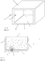
- FIG. 1A and 1B A refrigeration apparatus provided with an anti-condensation system of a known type is shown in Figures 1A and 1B .
- Such apparatus of known type has a product storage compartment defined within a casing or main body, comprising an inner case I and an outer case O, in which the compartment is defined by the inner case I appropriately shaped and provided with an open side for access thereto.
- the inner case I is typically made of a plastics (polystyrene) material and the outer case O is typically made of a metallic material.
- a door is appropriately coupled, usually rotatably by means of hinges, to the outer case O in order to close the compartment and as much as possible maintain the temperature in its interior S.
- the compartment is appropriately cooled by means of one or more evaporator elements, not shown, belonging to a refrigeration system.
- a refrigeration system of known type is typically composed of a compressor, a condenser, an expansion valve and one or more evaporators. These elements are connected together by means of appropriate tubes within which the liquid refrigerant flows.
- the refrigeration system there is a branch in which the liquid refrigerant that flows within the pipes is at low temperature, the branch comprising the evaporator, and a branch in which the temperature of the liquid refrigerant that flows within the tubes is at a higher temperature, the branch comprising the condenser downstream of the compressor.
- the space of predetermined thickness W defined between the inner case I and the outer case O is filled with an insulating material such as foam (see Fig. 1 B) .
- the outer case O is externally coupled to the inner case I at one of its edges OE that connects to a front edge (IE) of the inner case I.
- This front edge IE extends around the open side of the inner case I.
- heating element H that is fixed to the front edge IE of the inner case I.
- the heating element H corresponds to the tube of the cooling circuit in which the liquid refrigerant flows at high temperature.
- the heating element H is positioned externally to the front edge IE of the inner case I and as close as possible to the edge IE of the outer case O. In this way, the formation of condensation water on the outer surface of the outer case O is prevented, particularly on the outer surface of its edge OE.
- the outer case is made of a metallic material that therefore has a good level of thermal conductivity.
- the heat that reaches the interior of the compartment reduces the energy efficiency of the apparatus or, in other words, requires a larger amount of energy to maintain the desired temperature value inside the compartment.
- the situation is then particularly critical due to the difficulty of controlling the temperature of the liquid refrigerant inside the heating element, which can reach high levels making the above-mentioned drawback more obvious.
- the aim of the present invention is therefore to resolve the drawbacks of the known art.
- One aim of the present invention is to produce a refrigeration apparatus, particularly a built-in apparatus, provided with an anti-condensation system that has a higher energy efficiency that the apparatuses of known type, while maintaining the advantages that said system affords.
- the present invention therefore refers to a refrigeration apparatus comprising:
- the heating element is embedded in the insulating material.
- the heating element is arranged in contact with the inner side of the front edge of the inner case.
- the door is associated to said body, preferably to the outer case.
- the apparatus comprises a refrigeration system comprising a compressor, a condenser, a lamination element and one or more evaporators, said elements of the refrigeration system being coupled by means of tubes within which flows a liquid refrigerant.
- the heating element is composed of a portion of the tubes of said refrigeration system arranged downstream of the compressor and upstream of the lamination element.
- the heating element is composed of a portion of the tubes of said refrigeration system arranged downstream of the condenser and upstream of the lamination element.
- the front edge comprises one or more indented areas adapted to define a housing area for the heating element, more preferably adapted to define a supporting surface for the heating element.
- the apparatus comprises a fixing device for fixing the heating element to the inner case.
- the fixing device allows the fixing of the heating element to the front edge of the inner case.
- the fixing device comprises at least one clip.
- the clip comprises a first portion adapted to be disposed in abutment with the outer side of the front edge and a second portion adapted to contact at least partially the heating element. More preferably, the first portion of the clip comprises a bent portion adapted to be inserted in snap-in manner and in abutment to the outer side of the front edge and/or the second portion comprises a bent portion adapted to be engage in a snap-in manner the inner side of the front edge.
- the inner case is made of a plastics material and/or the outer case is made of a metallic material.
- the apparatus of the invention is a built-in apparatus and the outer case is shaped to be received in a containment structure.
- the present invention relates to an assembly comprising a containment structure and a refrigeration apparatus, wherein said apparatus is made in accordance with that described above.
- the present invention has proved to be particularly advantageous in the production of a built-in refrigeration apparatus, described below, comprising a casing equipped with a freezer compartment and a refrigerator compartment opening frontally, arranged one above the other, and provided with corresponding vertical closing doors. It should be noted, however, that the present invention is not limited to this embodiment. On the contrary, the application of the present invention is advantageous in refrigeration apparatuses in general comprising a casing comprising at least one refrigeration compartment and/or at least one freezer compartment with a closing door appropriately associated to said compartment, of any shape and/or position.
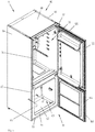
- Figure 1 shows a built-in refrigeration apparatus assembled within a containment structure 100 according to a preferred embodiment of the invention.
- the containment structure 100 is composed of a unit element, better illustrated in Figure 4 , preferably comprising a box-shaped structure having two parallel side walls 101 a, 101 b, one top wall 101 c and one bottom wall 101 d.
- the space defined by these walls preferably corresponds to the external shape of the refrigeration apparatus 1 to be contained.
- the refrigeration device 1 is preferably fixed to the structure 100 by means of appropriate connection means (not shown).
- the containment structure may be differently produced, either on the basis of the actual shape of the refrigeration apparatus to be received, or on the basis of the different aesthetic and/or assembly requirements.
- the built-in refrigeration apparatus 1 hereinafter for the sake of simplicity indicated only as apparatus 1, preferably comprises a casing or body 10 in which are preferably identified a refrigerator compartment 30 and a freezer compartment 60.
- the apparatus 1 shown and described here refers therefore to a combined solution in which the refrigeration compartment 30 is preferably positioned above the freezer compartment 60.
- the refrigerator compartment 30, as is known, is preferably adapted to keep the goods stored therein at a cooling temperature typically within a temperature range of between 1° and 10°C.
- the freezer compartment 60 is capable preferably of freezing the goods stored therein at a freezing temperature typically within a temperature range of between -16°C and -28°C.
- the casing or body 10 comprises an inner case 32 with a corresponding access aperture 34 adapted to define said refrigerator compartment 30, and an inner case 62 with respective access aperture 64 adapted to define said freezer compartment 60.
- compartments 30, 60 are shown empty, in other words without said shelves and/or drawers.
- the inner cases 32, 62 are preferably made of a polymer plastics material, such as polystyrene PS.
- the inner cases 32, 62 are also normally referred to as inner liners.
- the two inner cases that define the refrigerator compartment and freezer compartment respectively are composed of two separate elements.
- the two inner cases may belong to the same monolithic body.
- the body 10 comprises an outer case 80 externally coupled to the inner cases 32, 62 in order to define in relation to these inner cases 32 a space 82.
- the outer case 80 also defines the visible outer part, before its insertion into the structure 100, of the apparatus 1.
- the outer case 80 is preferably made, at least partially, of a metallic material, such as magnetic steel or magnetic enameled sheet metal.
- the outer case 80 preferably comprises two side walls 84, 86, a top wall 88, a bottom wall 90 and a back wall 92.
- the apparatus 1 preferably comprises a top door 120 associated to the access aperture 34 of the refrigerator compartment 30 and a bottom door 140 associated to the access aperture 34 of the refrigerator compartment 30 and a bottom door 140 associated to the access aperture 64 of the freezer compartment 60 that enables the hermetic closure of the respective compartments 30, 60.
- a single door adapted to close both compartments could be envisaged.
- the doors 120, 140 are preferably connected rotatably to the body 10, more preferably to the outer case 80.
- the doors 120, 140 are preferably connected rotatably by means of hinges.
- the doors 120, 140 are preferably provided with seals 122, 144 arranged around their inner surface facing said compartments 30, 60 and in a position such as to create a hermetic closure of the doors 120, 140 against an edge 85 of the outer case 80, as better described below.
- each seal 122, 144 is provided with magnetic elements, not visible in the Figures, adapted to perform a magnetic action in order to keep the door shut when the seals 122, 144 rest on the edge 85 of the outer case 80.
- the outer case 80, or at least its edge 85 or part thereof, is made of a ferromagnetic material.
- the apparatus 1 also comprises a refrigeration system 160 for cooling the compartments 30, 60, preferably comprising a compressor 162, a condenser 164, a lamination element (not shown) and one or more evaporators 166, 168, preferably associated to the refrigerator compartment 30 and to the freezer compartment respectively, visible for example in Figures 6 and 7 .
- the elements of the refrigeration system 160 are connected together by means of appropriate tubes within which flows the liquid refrigerant.
- the evaporators 166, 168 are preferably composed of a tube made of a material having good thermal conductivity (for example metals such as aluminum or copper), which is appropriately shaped to interact with the respective compartment to be cooled or frozen.
- a material having good thermal conductivity for example metals such as aluminum or copper
- the tube that constitutes the evaporator winds externally round the inner case that defines the compartment, as in the present embodiment.
- the evaporator or evaporators can be associated to the respective compartment in a different way, for example housed partially or totally inside the compartment itself. Ventilation systems may also be present, capable of appropriately conveying cold air generated by said evaporators into the compartments.
- the compressor 162 is preferably accommodated in the back part of the apparatus, preferably outside the outer case 80.
- the refrigeration system 160 comprises a heating element 142 comprising a portion of tube inside which flows the liquid refrigerant.
- This heating element 142 preferably comprises a portion of the tube located downstream of the compressor 162 and upstream of the lamination element.
- the heating element 142 preferably comprises a portion of the tube downstream of the compressor 162 that connects the condenser 164 to the lamination element.
- the heating element 142 is used in an anti-condensation system 200 preferably associated to the freezer compartment 60, as shown and described in detail below.
- the outer case 80 is externally coupled to the inner cases 32, 62 so as to define a space (82) therebetween.
- This space 82 advantageously defines and insulating space and is preferably filled with an insulating material that facilitates as much as possible the maintenance of the temperature inside the compartments 30, 60.
- the insulating material preferably comprises an expanded material, more preferably a polyurethane foam.
- the side walls 84, 86 of the outer case are coupled at the front, and at least partially, to the inner cases 32, 62.
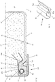
- Figure 10 shows the detail of the coupling area between the left side wall 84 and the inner case 62 of the freezer compartment 60.
- the inner case 62 preferably comprises a front edge 66 that extends around the access aperture 64.
- the front edge 66 is preferably arranged, in operating conditions, i.e. when the apparatus 1 is switched on, on a vertical plane and substantially defines a frame for said access aperture 64.
- the front edge 66 has an outer side 68 and an inner side 69, the latter facing the insulating space 82.
- the edge 85 is preferably made by means of a bent profile of the side part 84. As previously stated, on the edge 85 of the outer case 80 rests the seal 122, 144 of the door 120, 140 when the latter is in its closed position.
- the anti-condensation system 200 associated to said coupling area between the inner case 62 and the outer case 80, or side wall 84, is the anti-condensation system 200.
- the heating element 142 of the anti-condensation system 200 is accommodated at the inner side 69 of the front edge 66, inside the insulating space 82.
- the heating element 142 is embedded in the insulating material.
- the heating element 142 preferably extends substantially along the entire front edge 66 of the inner case 62 (on its inner side 69) of the freezer compartment 60, as can be appreciated from the view shown in Fig. 9 .
- the heating element could include lower sections of the front edge.
- the front edge too of the inner case that defines the refrigerator compartment could be equipped with a similar heating element.
- the need for an anti-condensation system is particularly strong in respect of the freezer compartment.
- condensation water tends to form.
- the presence of the heating element 142 allows thermal energy to be transmitted towards these areas in order to evaporate the humidity which is the cause of condensation water and in general to heat these areas so as to bring their temperature closer to ambient temperature and thus discourage the buildup of condensation thereon.
- the front edge 66 of the inner case 62 which, being made of a plastics material (such as polystyrene), presents a certain thermal resistance and in general a thermal resistance greater than the metal of which the edge 85 is composed. Consequently, the heat generated by the heating element 142 is partly shielded by the inner case 62 and reaches at a lower percentage the edge 85 of the outer case 80.
- the applicant has found that the amount of heat that reaches the edge 85 is however sufficient to fulfill the desired anti-condensation purpose.
- the energy efficiency of the apparatus 1 is therefore higher than the systems of know type previously described.
- the heating element 142 is preferably in contact with the inner side 69 of the front edge 66.
- the heating element need not necessarily be placed in contact with the front edge but arranged inside the insulating space at a certain distance from the front edge. This distance will be appropriately chosen so that the heat generated by the heating element that reaches the edge of the outer case is sufficient to fulfill the desired anti-condensation purpose.
- the front edge 66 comprises one or more indented areas 67 adapted to define a housing area for the heating element 142 and preferably to define a supporting surface 67a for the heating element 142.
- indented areas 67 there are preferably four indented areas 67, one for each side of the front edge.
- these areas can extend differently and comprise one or more sections along the front edge. In other variations, these indented areas might not be present.
- the heating element 142 of the anti-condensation system is fixed to the front edge 66 of the inner case 62 and preferably to its inner edge 69, by means of a fixing device preferably comprising one or more clips 150.
- the clip 150 preferably two or more per side (two per side in the embodiment shown), preferably comprises a first portion 152 adapted to be disposed in abutment with said outer side 68 of said front edge 66 and a second portion 154 adapted to contact at least partially said heating element 142 and to hold it preferably in abutment against the supporting surface 67a of the indented portions 67.
- the clip 150 is substantially U-shaped.
- the first portion 152 of the clip 150 then preferably has a bent portion 152a adapted to be inserted in a snap-in manner into the rib 67b defined externally by the indented portion 67.
- the second portion 154 of the clip 150 then preferably has a bent portion 154a adapted to engage in a snap-in manner onto the indented portion 67. This encourages the hold of the clip 150 on the front edge 66.
- the clips 150 keep the heating element 142 in contact with the inner surface 69 of the front edge 66, particularly during the production phases when the insulating material is injected into the insulating space 82.
- the clips 150 encourage the automation of the phases of production of the apparatus 1, more particularly the phases of fitting the heating element 142 to the front edge 66.
- said heating element 142 can be fixed by automatic positioning of the clips 150, by manipulator robots, for example, or some other automatic device.
- a portion of the outer case 80 comprises an internally projecting wing 89 adapted to wrap at least partially round the heating element 142 and the fitting clips 150.
- the wing 89 is preferably composed of an extension of the bent edge 85.
- this projecting wing 89 allows the reciprocal connection of the side wall 84 of the outer case 80 to the front edge 66 of the inner case 62 and allows them to be held in the correct mutual position, particularly during the production phases when the insulating material is injected into the insulating space 82.
- this projecting wing 89 advantageously encourages the heating element 142 to be held in place, particularly during the production phases when the insulating material is injected into the insulating space 82.
- clips 150 are preferred that act as an invitation for the wing 89 during the movement of the side wall 84 towards the front edge 66.
- the clips 150 also encourage automation of the phases of production of the apparatus 1, more particularly the phases of fitting the side wall 84 to the front edge 66 of the inner case 62.
- this wing need not necessarily be present.
- the present invention allows the preestablished aims to be achieved.
- it allows a refrigeration apparatus with a higher energy efficiency than the apparatuses of known type to be produced.
Landscapes
- Engineering & Computer Science (AREA)
- Chemical & Material Sciences (AREA)
- Combustion & Propulsion (AREA)
- Physics & Mathematics (AREA)
- Mechanical Engineering (AREA)
- Thermal Sciences (AREA)
- General Engineering & Computer Science (AREA)
- Table Devices Or Equipment (AREA)
- Thermotherapy And Cooling Therapy Devices (AREA)
- Refrigerator Housings (AREA)
Abstract
A refrigerating apparatus (1) comprising a casing or body (10) comprising an inner case (32) with an access aperture (34) adapted to define a compartment for storing goods to be cooled or frozen, and an outer case (80, 84, 86, 88, 90) that is externally coupled to said inner case (32). The internal case (32) comprises a front edge (66) having an outer side (68) and an inner side (69) and the outer case (80, 84, 86, 88, 90) comprises an edge (85) that is coupled at the outer side (68) of the front edge (66).
A heating element (142) associated to the body (10) and adapted to prevent the formation of condensation between the body (10) and a door (140) closing the compartment.
The heating element (142) is accommodated at the inner side (69) of the front edge (66) of the inner case (32).
Description
- This invention lies within the technical field of the production of refrigeration apparatuses, for example a refrigerator or a freezer or a combined solution. More particularly, this invention relates to the production of an anti-condensation system with which such apparatus is provided.
- A first type of refrigeration apparatus of a known type, domestic and/or professional, comprises a casing provided with a refrigeration compartment adapted to keep the goods stored therein at a cooling temperature ranging typically between 1 ° and 10°C.
- Another type of refrigeration apparatus of a known type, domestic and/or professional, comprises a casing equipped with a freezer compartment adapted to freeze the goods stored therein at a freezing temperature ranging typically between a temperature of -16° and -28°C. Typically, the freezer compartment is used to store goods for longer periods of time than the refrigeration compartment.
- Other widespread refrigeration apparatuses are composed of solutions of a combined type that include the presence in the casing of a refrigeration compartment and a freezer compartment, typically arranged one above the other.
- The refrigeration and/or freezer compartment, preferably box-shaped, is provided with an access aperture for the introduction/extraction of goods which is associated to a door for the hermetic closure of the compartment.
- The apparatus can be provided with one door or several doors, for example one door for the refrigeration compartment and one door for the freezer compartment in the case of a combined system.
- The refrigeration apparatuses of known type can constitute a stand-alone or free-standing product or can be built-in, meaning appropriately configured in order to be accommodated in special structures arranged within a certain environment, typically within a kitchen cabinet. This structure can completely hide the apparatus or, in other cases, accommodate it at least partly, for example by covering the side walls thereof and leaving the door or doors of the apparatus accessible.
- In the following description general reference may be made to a compartment, which may mean indifferently a refrigeration compartment or a freezer compartment.
- Due to the temperature difference between the inside and outside of the compartment, particularly at the access aperture, the generation/build-up of condensation water is known.
- In order to prevent the formation of this condensation water which, for example, in the case of a freezer compartment can freeze and prevent the door from opening, anti-condensation systems are known that use heating elements that serve to heat the mutual contact surfaces between the door and access aperture of the compartment so as to discourage/counteract the condensation that would occur on these surfaces if they were cold. These heating elements are therefore typically accommodated inside the casing near the mutual contact surfaces between the door and compartment.
- The heating elements are typically composed of a portion of the refrigeration system pipe, appropriately shaped, within which flows the high-temperature liquid refrigerant.
- A refrigeration apparatus provided with an anti-condensation system of a known type is shown in
Figures 1A and 1B . - Such apparatus of known type has a product storage compartment defined within a casing or main body, comprising an inner case I and an outer case O, in which the compartment is defined by the inner case I appropriately shaped and provided with an open side for access thereto.
- The inner case I is typically made of a plastics (polystyrene) material and the outer case O is typically made of a metallic material.
- A door, not shown, is appropriately coupled, usually rotatably by means of hinges, to the outer case O in order to close the compartment and as much as possible maintain the temperature in its interior S.
- The compartment is appropriately cooled by means of one or more evaporator elements, not shown, belonging to a refrigeration system.
- A refrigeration system of known type is typically composed of a compressor, a condenser, an expansion valve and one or more evaporators. These elements are connected together by means of appropriate tubes within which the liquid refrigerant flows. As is known, in the refrigeration system there is a branch in which the liquid refrigerant that flows within the pipes is at low temperature, the branch comprising the evaporator, and a branch in which the temperature of the liquid refrigerant that flows within the tubes is at a higher temperature, the branch comprising the condenser downstream of the compressor.
- In order to help maintain the temperature in the interior S of the compartment, the space of predetermined thickness W defined between the inner case I and the outer case O is filled with an insulating material such as foam (see
Fig. 1 B) . The outer case O is externally coupled to the inner case I at one of its edges OE that connects to a front edge (IE) of the inner case I. This front edge IE extends around the open side of the inner case I. - In this area, which also corresponds to the supporting area of the door when the latter is closed, is accommodated a heating element H that is fixed to the front edge IE of the inner case I. The heating element H corresponds to the tube of the cooling circuit in which the liquid refrigerant flows at high temperature.
- The heating element H is positioned externally to the front edge IE of the inner case I and as close as possible to the edge IE of the outer case O. In this way, the formation of condensation water on the outer surface of the outer case O is prevented, particularly on the outer surface of its edge OE.
- A refrigeration apparatus provided with an anti-condensation system of this type is also described in
US2015192347A1 . - The applicant has pointed out that such a state-of-the-art apparatus has a few drawbacks.
- One of the drawbacks found with this solution is represented by the fact that part of the heat produced by the heating element spreads along the edge of the outer case, reaching the interior of the compartment.
- This spread is then further encouraged by the fact that the outer case is made of a metallic material that therefore has a good level of thermal conductivity. The heat that reaches the interior of the compartment reduces the energy efficiency of the apparatus or, in other words, requires a larger amount of energy to maintain the desired temperature value inside the compartment.
- This reduction in efficiency is even more obvious in built-in apparatuses because the space between the inner and outer case has a smaller thickness than the free-standing solutions and so the heating element is accommodated in a closer position to the compartment.
- The situation is then particularly critical due to the difficulty of controlling the temperature of the liquid refrigerant inside the heating element, which can reach high levels making the above-mentioned drawback more obvious.
- The aim of the present invention is therefore to resolve the drawbacks of the known art.
- One aim of the present invention is to produce a refrigeration apparatus, particularly a built-in apparatus, provided with an anti-condensation system that has a higher energy efficiency that the apparatuses of known type, while maintaining the advantages that said system affords.
- The applicant has found that by producing a refrigeration apparatus having a compartment for storing goods comprising an inner case and an outer case externally coupled to the inner case in which a heating element is accommodated at an inner side of the inner case, it is possible to improve the energy efficiency of the apparatus compared to the apparatuses of known type. In its first aspect, the present invention therefore refers to a refrigeration apparatus comprising:
- a casing or body comprising an inner case with an access aperture adapted to define a compartment for storing goods to be cooled or frozen, and an outer case that is externally coupled to said inner case so as to define an insulating space therebetween, which is filled with an insulating material, said inner case comprising a front edge extending around said access aperture, said front edge having an outer side and an inner side facing said insulating space, wherein said outer case comprises an edge which is coupled at said outer side of said front edge of said inner case;
- a door for the hermetic closure of said access aperture of said compartment, said door being adapted to be disposed in abutment against said edge of said outer case;
- a heating element associated to said body and adapted to prevent the formation of condensation between said body and said door;
- According to a first preferred embodiment, the heating element is embedded in the insulating material.
- Preferably, the heating element is arranged in contact with the inner side of the front edge of the inner case.
- In a preferred embodiment, the door is associated to said body, preferably to the outer case.
- According to a preferred embodiment of the invention, the apparatus comprises a refrigeration system comprising a compressor, a condenser, a lamination element and one or more evaporators, said elements of the refrigeration system being coupled by means of tubes within which flows a liquid refrigerant.
- Preferably, the heating element is composed of a portion of the tubes of said refrigeration system arranged downstream of the compressor and upstream of the lamination element.
- More preferably, the heating element is composed of a portion of the tubes of said refrigeration system arranged downstream of the condenser and upstream of the lamination element.
- In a preferred embodiment, the front edge comprises one or more indented areas adapted to define a housing area for the heating element, more preferably adapted to define a supporting surface for the heating element.
- According to a preferred embodiment of the invention, the apparatus comprises a fixing device for fixing the heating element to the inner case.
- Preferably, the fixing device allows the fixing of the heating element to the front edge of the inner case.
- In a preferred embodiment, the fixing device comprises at least one clip.
- Preferably, the clip comprises a first portion adapted to be disposed in abutment with the outer side of the front edge and a second portion adapted to contact at least partially the heating element. More preferably, the first portion of the clip comprises a bent portion adapted to be inserted in snap-in manner and in abutment to the outer side of the front edge and/or the second portion comprises a bent portion adapted to be engage in a snap-in manner the inner side of the front edge.
- In a preferred embodiment, the inner case is made of a plastics material and/or the outer case is made of a metallic material.
- Preferably, the apparatus of the invention is a built-in apparatus and the outer case is shaped to be received in a containment structure.
- In a second of its aspects, the present invention relates to an assembly comprising a containment structure and a refrigeration apparatus, wherein said apparatus is made in accordance with that described above.
- Further features and advantages of the present invention will be explained below by means of one of the preferred but not exclusive embodiments thereof illustrated, by way of non-limiting example, with reference to the accompanying drawings.
- In the drawings, characteristics and/or corresponding or equivalent component parts of the present invention are identified by the same reference numerals. In particular, in the Figures:
-
Fig. 1A shows in an axonometric view of a component of a refrigeration apparatus according to the known art; -
Fig. 1B shows a cross-sectional view of a detail of the component inFig. 1 A Aalong section plane I°-I°; -
Fig. 2 is an axonometric view of a built-in refrigeration apparatus inserted in a containment structure according to a preferred embodiment of the invention; -
Fig. 3 shows the assembly inFigure 2 with the doors of the refrigeration apparatus open; -
Fig. 4 is a partially exploded view of the assembly inFigure 3 ; -
Fig. 5 shows the refrigeration apparatus inFigure 4 isolated from the rest and with some elements removed from its interior; -
Fig. 6 shows a plan view from the back of the refrigeration apparatus inFigure 5 ; -
Fig. 7 shows an exploded view from the back of the refrigeration apparatus inFigure 5 ; -
Fig. 8 shows the refrigeration apparatus inFig. 7 partially assembled and with some elements removed; -
Fig. 8a shows an enlarged detail ofFigure 8 ; -
Fig. 9 shows an exploded view of some of the parts inFigure 8 ; -
Fig. 10 shows a detail of the cross-sectional view inFig. 5 along section plane X°-X°; -
Fig. 11 shows an enlarged detail of an element inFigure 9 . - Despite the fact that the present invention is described below with reference to its preferred embodiment shown in the drawings, the present invention is not limited to the embodiment described below and shown in the Figures. On the contrary, the embodiment described and shown clarifies a few aspects of the present invention, the scope of which is defined by the claims.
- The present invention has proved to be particularly advantageous in the production of a built-in refrigeration apparatus, described below, comprising a casing equipped with a freezer compartment and a refrigerator compartment opening frontally, arranged one above the other, and provided with corresponding vertical closing doors. It should be noted, however, that the present invention is not limited to this embodiment. On the contrary, the application of the present invention is advantageous in refrigeration apparatuses in general comprising a casing comprising at least one refrigeration compartment and/or at least one freezer compartment with a closing door appropriately associated to said compartment, of any shape and/or position.
-
Figure 1 shows a built-in refrigeration apparatus assembled within acontainment structure 100 according to a preferred embodiment of the invention. - In the embodiment shown here, the
containment structure 100 is composed of a unit element, better illustrated inFigure 4 , preferably comprising a box-shaped structure having twoparallel side walls top wall 101 c and onebottom wall 101 d. The space defined by these walls preferably corresponds to the external shape of therefrigeration apparatus 1 to be contained. - The
refrigeration device 1 is preferably fixed to thestructure 100 by means of appropriate connection means (not shown). - It is obvious that in variations, the containment structure may be differently produced, either on the basis of the actual shape of the refrigeration apparatus to be received, or on the basis of the different aesthetic and/or assembly requirements.
- The built-in
refrigeration apparatus 1, hereinafter for the sake of simplicity indicated only asapparatus 1, preferably comprises a casing orbody 10 in which are preferably identified arefrigerator compartment 30 and afreezer compartment 60. - The
apparatus 1 shown and described here refers therefore to a combined solution in which therefrigeration compartment 30 is preferably positioned above thefreezer compartment 60. - In variations, not shown, different solutions can be envisaged comprising a different number of refrigerator and/or freezer compartments, possibly even just one.
- The
refrigerator compartment 30, as is known, is preferably adapted to keep the goods stored therein at a cooling temperature typically within a temperature range of between 1° and 10°C. - The
freezer compartment 60, as is known, is capable preferably of freezing the goods stored therein at a freezing temperature typically within a temperature range of between -16°C and -28°C. - As shown in
Figure 5 , the casing orbody 10 comprises aninner case 32 with acorresponding access aperture 34 adapted to define saidrefrigerator compartment 30, and aninner case 62 withrespective access aperture 64 adapted to define saidfreezer compartment 60. - Inside the
refrigerator compartment 30 andfreezer compartment 60, appropriate supporting shelves and/or drawers are arranged. - In the view in
Figure 5 , thecompartments - The
inner cases - The
inner cases - In the preferred embodiment shown and described here, the two inner cases that define the refrigerator compartment and freezer compartment respectively are composed of two separate elements. In variations, not shown, the two inner cases may belong to the same monolithic body.
- The
body 10 comprises anouter case 80 externally coupled to theinner cases space 82. - The
outer case 80 also defines the visible outer part, before its insertion into thestructure 100, of theapparatus 1. - The
outer case 80 is preferably made, at least partially, of a metallic material, such as magnetic steel or magnetic enameled sheet metal. - The
outer case 80 preferably comprises twoside walls top wall 88, abottom wall 90 and aback wall 92. - The
apparatus 1 preferably comprises atop door 120 associated to theaccess aperture 34 of therefrigerator compartment 30 and abottom door 140 associated to theaccess aperture 34 of therefrigerator compartment 30 and abottom door 140 associated to theaccess aperture 64 of thefreezer compartment 60 that enables the hermetic closure of therespective compartments - The
doors body 10, more preferably to theouter case 80. - The
doors - In order to enable the hermetic closure of
compartments doors seals compartments doors edge 85 of theouter case 80, as better described below. - Furthermore, preferably, each
seal seals edge 85 of theouter case 80. Clearly, such an arrangement presupposes that theouter case 80, or at least itsedge 85 or part thereof, is made of a ferromagnetic material. Theapparatus 1 also comprises arefrigeration system 160 for cooling thecompartments compressor 162, acondenser 164, a lamination element (not shown) and one ormore evaporators refrigerator compartment 30 and to the freezer compartment respectively, visible for example inFigures 6 and7 . - The elements of the
refrigeration system 160 are connected together by means of appropriate tubes within which flows the liquid refrigerant. - The
evaporators - In some embodiments, for example, the tube that constitutes the evaporator winds externally round the inner case that defines the compartment, as in the present embodiment. In variations, the evaporator or evaporators can be associated to the respective compartment in a different way, for example housed partially or totally inside the compartment itself. Ventilation systems may also be present, capable of appropriately conveying cold air generated by said evaporators into the compartments.
- The
compressor 162 is preferably accommodated in the back part of the apparatus, preferably outside theouter case 80. - The
refrigeration system 160 comprises aheating element 142 comprising a portion of tube inside which flows the liquid refrigerant. - This
heating element 142 preferably comprises a portion of the tube located downstream of thecompressor 162 and upstream of the lamination element. - In the embodiment of the present invention shown in the accompanying Figures, the
heating element 142 preferably comprises a portion of the tube downstream of thecompressor 162 that connects thecondenser 164 to the lamination element. - The
heating element 142 is used in ananti-condensation system 200 preferably associated to thefreezer compartment 60, as shown and described in detail below. - As previously said, the
outer case 80 is externally coupled to theinner cases - This
space 82 advantageously defines and insulating space and is preferably filled with an insulating material that facilitates as much as possible the maintenance of the temperature inside thecompartments - In particular, the
side walls inner cases -
Figure 10 shows the detail of the coupling area between theleft side wall 84 and theinner case 62 of thefreezer compartment 60. - The
inner case 62 preferably comprises afront edge 66 that extends around theaccess aperture 64. Thefront edge 66 is preferably arranged, in operating conditions, i.e. when theapparatus 1 is switched on, on a vertical plane and substantially defines a frame for saidaccess aperture 64. - The
front edge 66 has anouter side 68 and aninner side 69, the latter facing the insulatingspace 82. - To the
outer side 68 of thefront edge 66 is coupled theedge 85 of theouter case 80. - The
edge 85 is preferably made by means of a bent profile of theside part 84. As previously stated, on theedge 85 of theouter case 80 rests theseal door - According to one aspect of the present invention, associated to said coupling area between the
inner case 62 and theouter case 80, orside wall 84, is theanti-condensation system 200. - In particular, the
heating element 142 of theanti-condensation system 200 is accommodated at theinner side 69 of thefront edge 66, inside the insulatingspace 82. Preferably, theheating element 142 is embedded in the insulating material. - In the embodiment shown here, the
heating element 142 preferably extends substantially along the entirefront edge 66 of the inner case 62 (on its inner side 69) of thefreezer compartment 60, as can be appreciated from the view shown inFig. 9 . - In alternative variations, the heating element could include lower sections of the front edge.
- In other variations, the front edge too of the inner case that defines the refrigerator compartment could be equipped with a similar heating element. However, the need for an anti-condensation system is particularly strong in respect of the freezer compartment.
- In fact, due to the difference in temperature between the inside and outside of the
compartment 60, particularly at theedge 85 of theouter case 80 where theseal door - The presence of the
heating element 142 allows thermal energy to be transmitted towards these areas in order to evaporate the humidity which is the cause of condensation water and in general to heat these areas so as to bring their temperature closer to ambient temperature and thus discourage the buildup of condensation thereon. - Advantageously in the present solution, compared to the known art, in the route of transmission of the heat between the
heating element 142 and theedge 85 of theouter case 80 is also located thefront edge 66 of theinner case 62, which, being made of a plastics material (such as polystyrene), presents a certain thermal resistance and in general a thermal resistance greater than the metal of which theedge 85 is composed. Consequently, the heat generated by theheating element 142 is partly shielded by theinner case 62 and reaches at a lower percentage theedge 85 of theouter case 80. The applicant has found that the amount of heat that reaches theedge 85 is however sufficient to fulfill the desired anti-condensation purpose. It has also been found that at the same time the amount of heat produced by theheating element 142 that is instead spread along theedge 85 of theouter case 80 towards the inside of thecompartment 60 is reduced compared to the known art, and has a minimal or no influence on the increase in temperature inside thecompartment 60. Thus, advantageously, the problem found in the know art is overcome because a smaller amount of heat, substantially negligible for the purposes of increasing the temperature inside thecompartment 60, reaches the inside of thecompartment 60. - The energy efficiency of the
apparatus 1 is therefore higher than the systems of know type previously described. - In the embodiment shown here, the
heating element 142 is preferably in contact with theinner side 69 of thefront edge 66. - In advantageous variations, however, the heating element need not necessarily be placed in contact with the front edge but arranged inside the insulating space at a certain distance from the front edge. This distance will be appropriately chosen so that the heat generated by the heating element that reaches the edge of the outer case is sufficient to fulfill the desired anti-condensation purpose.
- In order to ease the positioning of
heating element 142 along thefront edge 66 of theinner case 62, thefront edge 66 comprises one or moreindented areas 67 adapted to define a housing area for theheating element 142 and preferably to define a supportingsurface 67a for theheating element 142. - In the embodiment shown here, there are preferably four
indented areas 67, one for each side of the front edge. - In advantageous variations, these areas can extend differently and comprise one or more sections along the front edge. In other variations, these indented areas might not be present.
- According to a second aspect of the present invention, the
heating element 142 of the anti-condensation system is fixed to thefront edge 66 of theinner case 62 and preferably to itsinner edge 69, by means of a fixing device preferably comprising one ormore clips 150. - The
clip 150, preferably two or more per side (two per side in the embodiment shown), preferably comprises afirst portion 152 adapted to be disposed in abutment with saidouter side 68 of saidfront edge 66 and asecond portion 154 adapted to contact at least partially saidheating element 142 and to hold it preferably in abutment against the supportingsurface 67a of theindented portions 67. - The
clip 150 is substantially U-shaped. - The
first portion 152 of theclip 150 then preferably has abent portion 152a adapted to be inserted in a snap-in manner into therib 67b defined externally by theindented portion 67. Thesecond portion 154 of theclip 150 then preferably has abent portion 154a adapted to engage in a snap-in manner onto theindented portion 67. This encourages the hold of theclip 150 on thefront edge 66. - Preferably, the
clips 150 keep theheating element 142 in contact with theinner surface 69 of thefront edge 66, particularly during the production phases when the insulating material is injected into the insulatingspace 82. - Advantageously, the
clips 150 encourage the automation of the phases of production of theapparatus 1, more particularly the phases of fitting theheating element 142 to thefront edge 66. In fact, after having positioned, by means of a robot for example, theheating element 142 in contact with thefront edge 66, saidheating element 142 can be fixed by automatic positioning of theclips 150, by manipulator robots, for example, or some other automatic device. - Furthermore, preferably, a portion of the
outer case 80, more particularly preferably a portion of theside wall 84, comprises an internally projectingwing 89 adapted to wrap at least partially round theheating element 142 and the fitting clips 150. - In the embodiment shown here, the
wing 89 is preferably composed of an extension of thebent edge 85. - Advantageously, this projecting
wing 89 allows the reciprocal connection of theside wall 84 of theouter case 80 to thefront edge 66 of theinner case 62 and allows them to be held in the correct mutual position, particularly during the production phases when the insulating material is injected into the insulatingspace 82. - Furthermore, this projecting
wing 89 advantageously encourages theheating element 142 to be held in place, particularly during the production phases when the insulating material is injected into the insulatingspace 82. - Again advantageously, during the reciprocal phases of fitting the
side wall 84 of theouter case 80 to thefront edge 66 of theinner case 62, fitting theside wall 84 and positioning the projectingwing 89 in the desired position, i.e. as shown inFigure 10 ,clips 150 are preferred that act as an invitation for thewing 89 during the movement of theside wall 84 towards thefront edge 66. - The
clips 150 also encourage automation of the phases of production of theapparatus 1, more particularly the phases of fitting theside wall 84 to thefront edge 66 of theinner case 62. - In advantageous variations, however, this wing need not necessarily be present.
- It has therefore been shown that the present invention allows the preestablished aims to be achieved. In particular, it allows a refrigeration apparatus with a higher energy efficiency than the apparatuses of known type to be produced.
- Although this invention has been described with reference to the particular embodiment shown in the Figures, it should be noted that the present invention is not limited to the particular embodiment represented and described. On the contrary, additional variations of the embodiment described fall within the scope of the present invention, a scope defined by the claims.
Claims (10)
- A refrigerating apparatus (1) comprising:- a casing or body (10) comprising an inner case (32) with an access aperture (34) adapted to define a compartment for storing goods to be cooled or frozen, and an outer case (80, 84, 86, 88, 90) that is externally coupled to said inner case (32) so as to define an insulating space (82) therebetween, which is filled with an insulating material, said inner case (32) comprising a front edge (66) extending around said access aperture (34), said front edge (66) having an outer side (68) and an inner side (69) facing said insulating space (82), wherein said outer case (80, 84, 86, 88, 90) comprises an edge (85) which is coupled at said outer side (68) of said front edge (66) of said inner case (32);- a door (140) for the hermetic closure of said access aperture (34) of said compartment, said door (140) being adapted to be disposed in abutment against said edge (85) of said outer case (80, 84, 86, 88, 90);- a heating element (142) associated to said body (10) and adapted to prevent the formation of dew condensation between said body (10) and said door (140);characterized in that said heating element (142) is accommodated at said inner side (69) of said front edge (66) and inside said insulating space (82).
- Apparatus (1) according to claim 1), characterized in that said heating element (142) is embedded in said insulating material.
- Apparatus (1) according to any one of the preceding claims, characterized in that said heating element (142) is arranged in contact with said inner side (69) of said front edge (66) of said inner case (32).
- Apparatus (1) according to any one of the preceding claim, characterized in that said front edge (66) comprises one or more indented areas (67) adapted to define a housing area for said heating element (142), more preferably adapted to define a supporting surface (67a) for said heating element (142).
- Apparatus (1) according to any one of the preceding claims, characterized in that it comprises a fixing device for fixing said heating element (142) to said inner case (32).
- Apparatus (1) according to claim 5), characterized in that said fixing device allows the fixing of said heating element (142) to said front edge (66) of said inner case (32).
- Apparatus (1) according to claim 5) or 6), characterized in that said fixing device comprises at least one clip (150).
- Apparatus (1) according to claim 7), characterized in that said clip (150) comprises a first portion (152) adapted to be disposed in abutment with said outer side (68) of said front edge (66) and a second portion (154) adapted to contact at least partially said heating element (142).
- Apparatus (1) according to claim 8), characterized in that said first portion (152) of said clip (150) comprises a bent portion (152a) adapted to be inserted in snap-in manner and in abutment to said outer side (68) of said front edge (66) and/or said second portion (154) comprises a bent portion (154a) adapted to engage in a snap-in manner said inner side (69) of said front edge (66).
- Apparatus (1) according to any one of the preceding claim, characterized in that it is a built-in apparatus (1) and in that said outer case (80, 84, 86, 88, 90) is shaped to be received in a containment structure (100).
Applications Claiming Priority (1)
| Application Number | Priority Date | Filing Date | Title |
|---|---|---|---|
| IT102016000115344A IT201600115344A1 (en) | 2016-11-15 | 2016-11-15 | REFRIGERATION SYSTEM, IN PARTICULAR RECESSED, WITH ANTI-CONDENSATION SYSTEM |
Publications (1)
| Publication Number | Publication Date |
|---|---|
| EP3321612A1 true EP3321612A1 (en) | 2018-05-16 |
Family
ID=58609727
Family Applications (1)
| Application Number | Title | Priority Date | Filing Date |
|---|---|---|---|
| EP17198919.7A Withdrawn EP3321612A1 (en) | 2016-11-15 | 2017-10-27 | Refrigeration apparatus, in particular a built-in apparatus, with an anti-condensation system |
Country Status (2)
| Country | Link |
|---|---|
| EP (1) | EP3321612A1 (en) |
| IT (1) | IT201600115344A1 (en) |
Citations (6)
| Publication number | Priority date | Publication date | Assignee | Title |
|---|---|---|---|---|
| JPS5336562U (en) * | 1976-09-03 | 1978-03-31 | ||
| JPS5783388U (en) * | 1980-11-12 | 1982-05-22 | ||
| JPS57108068U (en) * | 1980-12-24 | 1982-07-03 | ||
| JPS57108069U (en) * | 1980-12-24 | 1982-07-03 | ||
| US20150192347A1 (en) * | 2014-01-07 | 2015-07-09 | Samsung Electronics Co., Ltd. | Refrigerator |
| DE102015203147A1 (en) * | 2015-02-23 | 2016-08-25 | BSH Hausgeräte GmbH | Refrigerating appliance with frame heating |
-
2016
- 2016-11-15 IT IT102016000115344A patent/IT201600115344A1/en unknown
-
2017
- 2017-10-27 EP EP17198919.7A patent/EP3321612A1/en not_active Withdrawn
Patent Citations (6)
| Publication number | Priority date | Publication date | Assignee | Title |
|---|---|---|---|---|
| JPS5336562U (en) * | 1976-09-03 | 1978-03-31 | ||
| JPS5783388U (en) * | 1980-11-12 | 1982-05-22 | ||
| JPS57108068U (en) * | 1980-12-24 | 1982-07-03 | ||
| JPS57108069U (en) * | 1980-12-24 | 1982-07-03 | ||
| US20150192347A1 (en) * | 2014-01-07 | 2015-07-09 | Samsung Electronics Co., Ltd. | Refrigerator |
| DE102015203147A1 (en) * | 2015-02-23 | 2016-08-25 | BSH Hausgeräte GmbH | Refrigerating appliance with frame heating |
Also Published As
| Publication number | Publication date |
|---|---|
| IT201600115344A1 (en) | 2018-05-15 |
Similar Documents
| Publication | Publication Date | Title |
|---|---|---|
| EP2557380B1 (en) | Refrigerator | |
| RU2581735C2 (en) | Household refrigerator | |
| KR20120106098A (en) | Refrigerator | |
| EP3069090B1 (en) | Refrigerator | |
| CN102844638B (en) | Door panel, method for manufacturing a door panel and refrigerating appliance with a door panel | |
| US6574982B1 (en) | Icemaker fill tube assembly | |
| US8905502B2 (en) | Refrigerator | |
| KR20170116868A (en) | Refrigerator and drawer guide assembly thereof | |
| AU2016316427B2 (en) | Refrigerator | |
| JP2007064597A (en) | refrigerator | |
| CN208332806U (en) | A kind of horizontal frostless two-temperature freezer | |
| EP3106806A1 (en) | Refrigerator and refrigerant circulation apparatus and method for making ice | |
| US20040177637A1 (en) | Refrigerator methods and apparatus | |
| KR20150124111A (en) | Refrigerator and method of manufacturing same | |
| KR102094335B1 (en) | Control box for compressor | |
| JP2012220116A (en) | Refrigerator | |
| KR19990021540U (en) | Refrigerator | |
| JPWO2017017850A1 (en) | Freezer refrigerator | |
| US12385684B2 (en) | Refrigerator appliance | |
| WO2020121404A1 (en) | Refrigerator | |
| CN112005063B (en) | Refrigerator with heatable interior | |
| KR20060015865A (en) | Refrigerator | |
| KR100823295B1 (en) | Direct-cooling refrigerator | |
| IT201600115344A1 (en) | REFRIGERATION SYSTEM, IN PARTICULAR RECESSED, WITH ANTI-CONDENSATION SYSTEM | |
| JP2007085613A (en) | Refrigerator |
Legal Events
| Date | Code | Title | Description |
|---|---|---|---|
| PUAI | Public reference made under article 153(3) epc to a published international application that has entered the european phase |
Free format text: ORIGINAL CODE: 0009012 |
|
| AK | Designated contracting states |
Kind code of ref document: A1 Designated state(s): AL AT BE BG CH CY CZ DE DK EE ES FI FR GB GR HR HU IE IS IT LI LT LU LV MC MK MT NL NO PL PT RO RS SE SI SK SM TR |
|
| AX | Request for extension of the european patent |
Extension state: BA ME |
|
| STAA | Information on the status of an ep patent application or granted ep patent |
Free format text: STATUS: THE APPLICATION IS DEEMED TO BE WITHDRAWN |
|
| 18D | Application deemed to be withdrawn |
Effective date: 20181117 |