WO2020121404A1 - Refrigerator - Google Patents
Refrigerator Download PDFInfo
- Publication number
- WO2020121404A1 WO2020121404A1 PCT/JP2018/045493 JP2018045493W WO2020121404A1 WO 2020121404 A1 WO2020121404 A1 WO 2020121404A1 JP 2018045493 W JP2018045493 W JP 2018045493W WO 2020121404 A1 WO2020121404 A1 WO 2020121404A1
- Authority
- WO
- WIPO (PCT)
- Prior art keywords
- refrigerator
- temperature
- pipe
- path switching
- dew condensation
- Prior art date
Links
Images


Classifications
-
- F—MECHANICAL ENGINEERING; LIGHTING; HEATING; WEAPONS; BLASTING
- F25—REFRIGERATION OR COOLING; COMBINED HEATING AND REFRIGERATION SYSTEMS; HEAT PUMP SYSTEMS; MANUFACTURE OR STORAGE OF ICE; LIQUEFACTION SOLIDIFICATION OF GASES
- F25D—REFRIGERATORS; COLD ROOMS; ICE-BOXES; COOLING OR FREEZING APPARATUS NOT OTHERWISE PROVIDED FOR
- F25D21/00—Defrosting; Preventing frosting; Removing condensed or defrost water
- F25D21/04—Preventing the formation of frost or condensate
Definitions
- the present invention relates to a refrigerator in which frost is suppressed.
- refrigerators are equipped with temperature sensors and humidity sensors in order to realize optimal operation in accordance with the environment in which the refrigerator is installed.
- the refrigerating compartment door is divided into left and right, a heater is installed on the partition plate between the refrigerating compartment doors, and the energization of the heater can be changed at a time rate according to the ambient room temperature and humidity.
- refrigerators that increase the energy saving by adjusting the surface temperature of the partition plate.
- the partition plate between the refrigerator compartment doors is protected from dew by heating with a heater, etc., but on the side of the refrigerator and the cabinet flange, condensation pipes and dew prevention pipes are placed to prevent dew condensation.
- the power consumption efficiency due to the heat generation of the heater is lower than the power consumption efficiency of the refrigerant circuit, so a measure against dew condensation that raises the outer temperature of the refrigerator by using the heat of the condensation pipe rather than causing the heater to generate heat is taken.
- Implementation is a shortcut to improve the energy efficiency of refrigerators.
- Patent Document 1 reports a technology that uses a four-way valve to switch the flow order of the refrigerant in a dew-proof pipe installed in the surfaces of the cabinet flange and the room partition. This is because the flow of the refrigerant in the refrigerant circuit changes when the user switches the dew-proof mode on the setting operation unit installed on the surface of the refrigerator. Specifically, when the dew prevention mode “weak” is selected, the flow of refrigerant in the refrigerant circuit is: compressor ⁇ condenser ⁇ four-way valve ⁇ radiating pipe ⁇ dew-proof pipe ⁇ four-way valve ⁇ capillary tube ⁇ evaporation The normal flow condition of the compressor ⁇ the compressor is achieved.
- the flow in the refrigerant circuit is as follows: compressor ⁇ condenser ⁇ four-way valve ⁇ dew-proof pipe ⁇ heat radiation pipe ⁇ four-way valve ⁇ capillary tube ⁇ evaporator ⁇ compressor. This is the reverse flow state, and the flow prioritizes dew prevention.
- Patent Document 2 reports a technique in which a four-way valve is used to reverse the refrigerant flow direction of a dew condensation suppressor provided at the opening edge of the box body. This is because when the amount of decompression by the decompression unit is increased or the machine room fan is operated at high speed, the ratio of the liquid occupying the pipe of the dew condensation suppressor increases. Therefore, the temperature decrease becomes large and the specific enthalpy of the refrigerant flowing into the pressure reducing section decreases, so that the enthalpy difference of the refrigerant that exchanges heat in the heat exchanging section can be increased, and the energy saving property can be improved. is there.
- Patent Document 1 the order in which the refrigerant flows in the heat radiating pipe and the dew proof pipe is switched depending on the strength of the dew proof mode.
- the four-way valve is provided on the downstream side of the condenser, the order is changed on the downstream side of the condenser connected to the discharge side of the compressor, and the temperature of the refrigerant is greatly reduced in the condenser. After that, the refrigerant is put in the dew-proof pipe. Therefore, a great effect cannot be obtained in improving the proof strength against dew.
- the Mollier diagram because the refrigerant after leaving the condenser enters the gas-liquid two-phase region, and the temperature of the refrigerant is constant in this region. Further, although the temperature is improved on the surface of each room partition, it is estimated that the temperature does not improve until the temperature of the door surface is improved, and the effect of improving the dew resistance is small.
- Patent Document 2 the direction of flow in the dew condensation prevention pipe (condensation suppressor) attached to the cabinet flange portion of the front opening edge of the box body is changed to a reverse direction by using a four-way valve. Then, although the energy saving property is enhanced depending on around which room of the refrigerator the part where a large amount of liquid refrigerant having a low temperature is present is flown, no mention is made of improvement of dew resistance. Further, it is only necessary to change the flow method after the radiator (condenser) provided on the machine room, the side surface, the ceiling surface, and the back surface of the box body.
- Patent Document 1 the temperature of the dew condensation prevention pipe is not so high, and in Patent Document 2, the temperature of the dew condensation prevention pipe can be lowered but cannot be increased. Therefore, in both cases, in the normal flow, the vapor-liquid two-phase or liquid-phase (supercooling region) of the Mollier diagram is used to reduce the temperature of the dew condensation prevention pipe installed on the cabinet flange part at the opening edge of the front of the refrigerator to save energy. I am trying to make it. When dealing with dew condensation, the flow is changed to reduce the degree of liquid phase in the dew condensation prevention pipe.
- the inside of the dew-prevention pipe can be raised only to the temperature of the gas-liquid two-phase level, and when the temperature is high and high, for example, the ambient temperature of the refrigerator is 30°C or higher, and the relative relative humidity is 90% or higher, further improvement of the dew-proof strength is not possible. I can't hope.
- Patent Document 1 and Patent Document 2 there is a problem that the dew proof stress cannot be improved so much at high temperature and high humidity, although the cost for improving the dew proof stress is high.
- the present invention has been made to solve the above problems, and an object thereof is to provide a refrigerator capable of improving the resistance to dew condensation when the temperature and humidity are high.
- a refrigerator includes a compressor, a flow path switching device, a machine room condenser, a surface condensation pipe, a dew condensation preventing pipe, a decompression device, and a cooler, and a refrigerant circuit in which a refrigerant circulates and a surrounding relative.
- An ambient humidity sensor that detects humidity, and a control device that controls the flow path switching device are provided, and the control device, when the relative humidity detected by the ambient humidity sensor is smaller than a preset reference value, ,
- the flow path switching device when the relative humidity detected by the ambient humidity sensor is equal to or higher than the reference value, the flow path switching device is switched so as to be in the reverse flow state. That is, the sensible heat change on the gas phase side can be used by controlling the flow path switching device so that the inlet of the dew condensation preventing pipe can be connected next to the compressor. Therefore, a high temperature refrigerant can be made to flow into the dew condensation prevention pipe, and the dew condensation resistance can be improved.
- FIG. 2 is a sectional view taken along the line AA of FIG. It is a figure which shows the time transition of the compressor operation etc. of the refrigerator which concerns on Embodiment 1 of this invention.
- It is the 1st connection diagram of the refrigerant piping inside the refrigerator concerning Embodiment 1 of the present invention.
- It is the 2nd connection diagram of the refrigerant piping inside the refrigerator concerning Embodiment 1 of the present invention.
- FIG. 1 the cabinet flange portion of the upper side of the refrigerator according to Embodiment 1 of the present invention
- FIG. 3 is a horizontal cross-sectional view of a cabinet flange portion on the left and right vertical sides of the refrigerator according to the first embodiment of the present invention (a sectional view taken along the line CC in FIG. 1 ).
- FIG. 3 is a vertical cross-sectional view (a cross-sectional view taken along the line DD in FIG. 1) of the ice-making compartment of the refrigerator according to the first embodiment of the present invention and the periphery of the partition between the small freezer compartment and the freezer compartment.
- FIG. 2 is a vertical cross-sectional view (a cross-sectional view taken along the line EE in FIG. 1) of the partition between the freezer compartment and the vegetable compartment of the refrigerator according to the first embodiment of the present invention.
- 9 is a vertical sectional view (a sectional view taken along the line DD in FIG. 1) in which butyl rubber is provided on the back surface of the front partition plate shown in FIG. 8. It is a disassembled perspective view which shows the structure of the refrigerator compartment left door of the refrigerator which concerns on Embodiment 1 of this invention. It is a disassembled perspective view which shows the structure of the refrigerator compartment right door of the refrigerator which concerns on Embodiment 1 of this invention. It is an exploded perspective view showing composition of a freezer compartment door of a refrigerator concerning Embodiment 1 of the present invention. 9 is a vertical cross-section (a cross-sectional view taken along the line DD in FIG. 1) showing a state where a vacuum heat insulating material is provided on the freezer compartment door shown in FIG.
- FIG. 8 It is a 1st block diagram of the refrigerant circuit of the refrigerator which concerns on Embodiment 1 of this invention. It is a 2nd block diagram of the refrigerant circuit of the refrigerator which concerns on Embodiment 1 of this invention.
- FIG. 3 is a Mollier diagram of the refrigerant circuit of the refrigerator according to Embodiment 1 of the present invention in a normal flow state and a reverse flow state.
- FIG. 18 is an enlarged view of the condensation step of FIG. 17 in a normal flow state.
- FIG. 18 is an enlarged view of the condensing process of FIG. 17 in a reverse flow state.
- FIG. 10 is a vertical cross-sectional view (a cross-sectional view taken along the line EE in FIG. 1) in which an injection hole is formed in the compartment partition shown in FIG. 9. It is a figure which shows the flow-path switching rate with respect to the relative humidity of the refrigerator which concerns on Embodiment 2 of this invention. It is a figure which shows the flow-path switching rate with respect to the relative humidity of the refrigerator which concerns on Embodiment 3 of this invention.
- FIG. 4 It is a block diagram of a refrigerant circuit of a refrigerator concerning Embodiment 4 of the present invention. It is a figure which shows the structure of the electromagnetic expansion valve used for the refrigerator which concerns on Embodiment 4 of this invention. It is a figure which shows the position of the valve body in the normal flow state of the electromagnetic expansion valve shown in FIG. It is a figure which shows the position of the valve body in the backflow state of the electromagnetic expansion valve shown in FIG. It is a 1st Mollier diagram in the normal flow state of the refrigerant circuit of the refrigerator concerning Embodiment 4 of the present invention. It is the 2nd Mollier diagram in the normal flow state of the refrigerant circuit of the refrigerator concerning Embodiment 4 of the present invention.
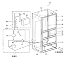
- Embodiment 1. 1 is a schematic front view of a refrigerator 100 according to Embodiment 1 of the present invention.
- FIG. 2 is a sectional view taken along the line AA of FIG.
- the configuration of the refrigerator 100 according to the first embodiment will be described.
- terms indicating directions are appropriately used, such as “upper”, “lower”, “right”, “left”, “front”, “rear”, etc. These terms are for the purpose of description and do not limit the present invention.
- “top”, “bottom”, “right”, “left”, “front”, “rear”, etc. are used when the refrigerator 100 is viewed from the front.
- the refrigerator 100 includes a plurality of storage chambers, and specifically, a refrigerating chamber 1, an ice making chamber 2, and a small freezing chamber 3.
- a freezer compartment 4 and a vegetable compartment 5 are provided.
- the refrigerating compartment 1 is provided at the top of the refrigerator 100, and the front opening is closed by two double doors that can be opened and closed.
- the two doors that open in a double door are composed of a refrigerating compartment left door 6 and a refrigerating compartment right door 7. Between the refrigerating compartment left door 6 and the refrigerating compartment right door 7, outside air enters between them.
- a partition plate 8 for preventing the above is provided.
- an ice making compartment 2 and a small freezing compartment 3 are arranged in parallel so that the storage compartment is pulled out to the user side when the ice making compartment door 92 and the small freezing compartment door 93 which are drawer type doors are pulled out. ..
- a vegetable compartment 5 is provided at the bottom of the refrigerator 100, and a freezing compartment 4 is provided above the vegetable compartment 5.
- the freezer compartment 4 is provided below the ice making compartment 2 and the small freezer compartment 3 arranged in parallel on the left and right sides, and above the vegetable compartment 5.
- the freezer compartment 4 and the vegetable compartment 5 are also configured such that the storage compartment is pulled out to the user side when the freezer compartment door 94 and the vegetable compartment door 95 which are drawer type doors are pulled out.
- each storage room is not limited to the first embodiment, and the arrangement of each storage room does not matter as long as it has a double door.
- the refrigerator 100 is equipped with an ambient temperature sensor 34 and an ambient humidity sensor 35.
- the ambient temperature sensor 34 detects the ambient temperature of the refrigerator 100.
- the ambient humidity sensor 35 detects the relative humidity around the refrigerator 100.
- the ambient temperature sensor 34 and the ambient humidity sensor 35 may be installed at any location as long as they can detect the ambient temperature and the relative humidity.
- the ambient temperature sensor 34 and the ambient humidity sensor 35 should be installed at positions that are not affected by the operation of the refrigerator 100, for example, the temperature effect of a condensation pipe (not shown) attached and fixed to the inside of the side surface of the refrigerator. desirable. Therefore, if the ambient temperature sensor 34 and the ambient humidity sensor 35 are installed at, for example, the upper hinge member (not shown) of the refrigerating compartment left door 6, they are not affected by the heat of the condensation pipe or the like.
- a control device 9 is provided on the back side of the refrigerator 100.
- the control device 9 includes, for example, dedicated hardware or a CPU (Central Processing Unit, central processing unit, processing device, arithmetic device, microprocessor, processor) that executes a program stored in a memory. There is.
- CPU Central Processing Unit, central processing unit, processing device, arithmetic device, microprocessor, processor
- a refrigerating compartment temperature sensor 38 for detecting the temperature of the refrigerating compartment 1 is installed on the surface of the refrigerating compartment air passage part 15.
- the refrigerating compartment temperature sensor 38 may be installed at any position as long as the temperature inside the refrigerating compartment 1 can be roughly observed.
- the control device 9 sends or shuts off the cool air to the refrigerating compartment 1 based on the temperature in the refrigerating compartment 1 detected by the refrigerating compartment temperature sensor 38 by operating the baffle 40 of the refrigerating compartment damper device 19. .
- this refrigerating compartment temperature sensor 38 controls energization to a heater (not shown) installed in the refrigerating compartment 1 for temperature compensation, a heater (not shown) installed in the partition plate 8, and the like. Used to do.
- three pockets 14 are attached along the height direction inside the refrigerator compartment left door 6 and the refrigerator compartment right door 7, and the interior of the refrigerator compartment 1 is divided into a plurality of shelves 13. ..
- a chilled room 17 (about 0° C.) lower than the temperature of the refrigerating room 1 (about 3° C.) is provided under the lowest shelf 13 in the refrigerating room 1.
- a refrigerating compartment air passage component 15 is provided on the back side of the refrigerating compartment 1, and a blowout port 16 through which air is blown from the refrigerating compartment blowing air passage 24 is formed in each part partitioned by the shelves 13.
- a refrigerating compartment damper device 19 is arranged between the internal fan 23 and the refrigerating compartment blowing air passage 24.
- a space between the inner box 11 and the outer box 12 is filled with a urethane foamed heat insulating material 10.
- the refrigerating compartment left door 6 is provided with a setting operation section 20 (broken line portion) by which a user can operate temperature setting and mode setting of each room.
- the refrigerating compartment 1 can be set to a temperature of weak (about 6° C.) to medium (about 3° C.) to strong (about 0° C.), and the freezer compartment 4 can be set.
- the temperature can be set from weak (about -16°C) to medium (about -18°C) to strong (about -20°C).
- the temperature of other rooms can be similarly set by the user operating the setting operation unit 20.
- the user can operate the setting operation unit 20 to set the energy saving priority mode and the dew condensation countermeasure mode, which will be described later.
- the setting operation section 20 is operated in the hole (not shown) on the right side of the refrigerating compartment left door 6.
- the panel 50 is inserted. Since a capacitance sensor is used in the setting operation unit 20, touching the surface of the setting operation unit 20 with a finger enables operation of temperature setting and mode setting.
- An automatic ice maker (not shown) is installed on the ceiling of the ice making room 2, and water can be supplied from a water supply tank (not shown) installed in the refrigerating room 1 to make ice.
- the small freezer compartment 3 is designed so that cool air is blown out from a fan grill 22 installed on the back side of the refrigerator 100 to be cooled. Since both the ice making chamber 2 and the small freezing chamber 3 are drawer type doors, a case (not shown) for storing ice and a case 25 for storing food are provided.
- freezer compartment 4 cool air is blown out from the fan grill 22 installed on the back side of the refrigerator 100, and the inside of the refrigerator is cooled to about ⁇ 18° C. at a medium temperature setting on a time average.
- the freezer compartment 4 is also a drawer type door, and is provided with an upper case 27 and a lower case 28. Further, a freezer compartment temperature sensor 39 for detecting the temperature of the freezer compartment 4 is attached to the fan grill 22.
- FIG. 3 is a diagram showing a time transition such as operation of the compressor 36 of the refrigerator 100 according to the first embodiment of the present invention.
- FIG. 3 shows the temperature of the freezer compartment temperature sensor 39, the temperature of the refrigerating compartment temperature sensor 38, and the operation of the compressor 36 on the vertical axis with respect to time on the horizontal axis.
- the operation of the compressor 36 is controlled based on the temperature of the freezer compartment temperature sensor 39.
- the compressor 36 stops (OFF point), and when the freezer compartment temperature sensor 39 rises to the second predetermined value, the compressor 36 is stopped.
- the compressor 36 is driven by the differential control in which the operation of the compressor 36 starts (ON point).
- the average temperature of the freezer compartment 4 is set to about -18°C, so the OFF point is set lower than -18°C and the ON point is set higher than -18°C.
- the control device 9 instructs opening and closing of the baffle 40 of the refrigerating compartment damper device 19 at the opening point and closing at the closing point.
- the temperature setting of the refrigerating compartment 1 is the medium setting, the average temperature of the refrigerating compartment 1 is set. Since the temperature is about 3°C, the open point is set higher than 3°C and the close point is set lower than 3°C.
- the vegetable compartment 5 is cooled from the outlet on the back side of the refrigerator 100, and is cooled to about 6° C. when the temperature setting is medium. Further, the vegetable compartment 5 is also a drawer type door, and is provided with an upper case 32 and a lower case 33.
- the inside of the refrigerator 100 is partitioned by room partitioning sections 21, 26, 31 along the height direction.
- the partition parts 21, 26, 31 are made of resin plate-shaped molded products at the top and bottom, and are filled with a heat insulating material made of urethane foam or a molded product such as Styrofoam, and fixed with screws at the top and bottom.
- a partition plate (not shown) made of a sheet metal is provided on the front side surface of each of the partition parts 21, 26, 31 so as to be magnetically attached to the gasket 67 with a magnet attached to the door. ing.
- FIG. 4 is a first connection diagram of the refrigerant pipes inside the refrigerator 100 according to the first embodiment of the present invention.
- FIG. 5 is a second connection diagram of the refrigerant pipes inside refrigerator 100 according to Embodiment 1 of the present invention.
- the components of the refrigerant circuit 102 of the refrigerator 100 are the compressor 36, the flow path switching device 42, the fin-tube type machine chamber condenser 43, and the left side surface.
- the flow path switching device 42 is, for example, a four-way valve, but is not limited thereto, and may be configured by combining a two-way valve and a three-way valve, for example.
- the compressor 36, the flow path switching device 42, the machine room condenser 43, and the dryer 51 are installed in the machine room 37 provided in the lower portion on the back side of the refrigerator 100.
- the ceiling surface condensing pipe 45 extends from the left side surface condensing pipe 44 on the left side surface to the ceiling surface, but may be connected from the right side surface condensing pipe 54 on the right side surface.
- the left side condensing pipe 44, the ceiling condensing pipe 45, the back side condensing pipe 46, and the right side condensing pipe 54 are fixed to the inner surface of the outer box 12 with aluminum tape, although not shown.
- the refrigerant circuit 102 is configured by sequentially connecting a compressor 36, a flow path switching device 42, a condensation system piping, a flow path switching device 42, a dryer 51, a capillary tube 48, a cooler 30, and a muffler 52.
- the condensing system piping is the machine room condenser 43, the left side condensing piping 44, the ceiling condensing piping 45, the back condensing piping 46, the right side condensing piping 54, and the dew condensation prevention piping 47.
- the refrigerator 100 is provided with a machine room cooling fan (not shown) that cools the machine room condenser 43 and the compressor 36, and an in-compartment fan 23 (see FIG. 2) that circulates cool air into the room. ing. Further, if it is on the downstream side of the flow path switching device 42 after passing through the condensation system pipe, two capillary tubes 48 are installed (in that case, a three-way valve is installed on the upstream side of the capillary tube 48), and the cooler 30 Multiple units may be installed.
- the machine room condenser 43, the ceiling surface condensation pipe 45, and the rear surface condensation pipe 46 may be provided if the condensation capacity can be gained only by the left side condensation pipe 44 and the right side condensation pipe 54. ..
- the right front side is the front side of the refrigerator 100, and the dew condensation prevention pipe 47 is arranged in the cabinet flange portion 55 and the compartment partitions 21, 26, 31. Further, the dew condensation prevention pipe 47 is connected to the right side condensing pipe 54 at the lower right side, is arranged from the lower side of the refrigerator 100 to the compartment partitions 21, 26, 31 and the like, and surrounds the periphery of the refrigerator compartment 1. .. After that, the dew condensation prevention pipe 47 returns to the lower side of the refrigerator 100 along the cabinet flange portion 55 as it is, and is connected to the flow path switching device 42 arranged in the machine room 37 through the lower left side surface.
- the left and right sides of the dew condensation prevention pipe 47 may be connected in reverse as shown in FIG.
- the dew condensation prevention pipe 47 is connected to the flow path switching device 42 arranged in the machine room 37 on the lower right side, and is arranged from the lower side of the refrigerator 100 to the room partition parts 21, 26, 31 and the like. , Around the refrigerator compartment 1. After that, the dew condensation preventing pipe 47 returns to the lower side of the refrigerator 100 along the cabinet flange portion 55 as it is, and passes through the lower left side face to be connected to the left side face condensing pipe 44.
- the turn of the dew condensation prevention pipe 47 arranged in the inter-room partition 21 that partitions the refrigerating compartment 1 and the ice-making compartment 2 is on the lower side. It is arranged so as to extend one turn in the direction.
- the ice making chamber 2 and the small freezing chamber 3 and the freezing chamber 4 may be arranged so as to extend upward from the turns arranged in the inter-room partition 26.
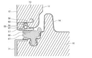
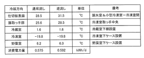
- FIG. 6 is a vertical cross-sectional view (a cross-sectional view taken along the line BB in FIG. 1) of the cabinet flange portion 55 on the upper side of the refrigerating compartment 1 of the refrigerator 100 according to Embodiment 1 of the present invention.
- FIG. 7 is a horizontal cross-sectional view (a cross-sectional view taken along the line CC of FIG. 1) of cabinet flange portions 55 on the left and right vertical sides of freezer compartment 4 of refrigerator 100 according to Embodiment 1 of the present invention.
- the cabinet flange portions 55 on the upper side and the left and right vertical sides of the refrigerator 100 are installed as shown in FIGS. 6 and 7.
- An inner box flange 57 having a recess 59 is inserted into an inner box grip-shaped portion 58 in which the outer box 12 made of sheet metal is bent, and a dew condensation prevention pipe 47 is installed in the recess 59.
- a sealing material 60 or the like is installed in the recess 59, and the dew condensation preventing pipe 47 installed thereon is provided so as to be in close contact with the outer box 12.
- the gasket 67 is provided with a magnet 68, and the magnetic force of the magnet 68 causes the gasket 67 to come into close contact with the outer casing 12 made of sheet metal.
- FIG. 8 is a vertical cross-sectional view around the room partition 26 between the ice making room 2 and the small freezing room 3 and the freezing room 4 of the refrigerator 100 according to the first embodiment of the present invention (the DD cross section arrow in FIG. 1).
- FIG. 9 is a vertical cross-sectional view (a cross-sectional view taken along the line EE in FIG. 1) around the partition 31 between the freezer compartment 4 and the vegetable compartment 5 of the refrigerator 100 according to Embodiment 1 of the present invention.
- FIG. 10 is a vertical sectional view (a sectional view taken along the line DD in FIG. 1) in which butyl rubber 66 is provided on the back surface of the surface partition plate 61 shown in FIG. Strictly speaking
- FIG. 8 is a vertical cross-sectional view around the room partition 26 between the small freezer compartment 3 and the freezer compartment 4.
- the parts configuration of the partition parts 21, 26, 31 of each room is basically the same. Further, in the inter-room partition 26 shown in FIG. 8, the surface partition plate 61 made of sheet metal is screwed and fixed to the resin partition main body 64 in which the upper surface 62 and the lower surface 63 are made of a resin plate.
- the surface partition plate 61 has its strength increased by the upper and lower ends being bent inward.
- the surface partition plate 61 provided between the ice making chamber 2 and the small freezing chamber 3 has its left and right ends bent inward.
- the partition main body 64 has its upper and lower ends extending to the outside of the refrigerator and wraps with the bent portions of the upper and lower ends of the surface partition plate 61, and a space is formed between the surface partition plate 61 and the partition body 64. Has been done. In the space, the dew condensation prevention pipe 47 is pressed so as to come into close contact with the inner surface of the surface partition plate 61. In the compartment partitioning portion 26, the dew-prevention prevention pipe 47 is pressed to the outside of the refrigerator from the back side by a heat insulating material 91 such as expanded polystyrene as shown in FIG. Further, in the inter-room partition section 31, as shown in FIG. 9, the dew condensation prevention pipe 47 is pressed to the outside of the storage by sticking a pressing sealing material 65 or the like to the partition body 64 side.
- a heat insulating material 91 such as expanded polystyrene
- the dew condensation prevention pipe 47 is pressed to the outside of the compartment with respect to the compartments 26 and 31, but the difference between the heat insulating material 91 and the pressing sealing material 65 is due to the component configuration of the refrigerator 100. is there. Therefore, there is no problem even if the pressing sealing material 65 is applied to the room partition 26 and the heat insulating material 91 is applied to the room partition 31.
- the pressing of the dew condensation prevention pipe 47 from the back side may not make good contact with the back side of the surface partition plate 61. In such a case, the heat of the dew condensation prevention pipe 47 is not transferred well. Therefore, as shown in FIG.
- butyl rubber 66 or the like is attached to the back surface of the surface partition plate 61 to increase the contact area between the dew condensation prevention pipe 47 and the surface partition plate 61, and the heat of the dew condensation prevention pipe 47 is separated from the surface partition plate. You may make it convey to the board 61.
- a magnet 68 is provided in the gasket 67 so that the gasket 67 comes into close contact with the surface partition plate 61 by magnetic force.
- the door handle portion 69 is a drawer type door, it is often attached to the upper and lower caps 70 and 71 of the door, and is often formed of resin. In a double door type door, it is often attached to the lower cap of the door. Since FIG. 8 is a vertical cross section between the small freezer compartment 3 and the freezer compartment 4, the small freezer compartment door 93 and the freezer compartment door 94 are drawer-type doors, and the cap 70 on the upper side of the freezer compartment door 94 has a door. A handle portion 69 is provided. Further, since FIG. 9 is a vertical cross section between the freezer compartment 4 and the vegetable compartment 5, the freezer compartment door 94 and the vegetable compartment door 95 are drawer type doors, and the cap 70 on the upper side of the vegetable compartment door 95 has a door. A handle portion 69 is provided.
- FIG. 11 is an exploded perspective view showing the configuration of refrigerating room left door 6 of refrigerator 100 according to Embodiment 1 of the present invention.
- FIG. 12 is an exploded perspective view showing the configuration of refrigerating room right door 7 of refrigerator 100 according to Embodiment 1 of the present invention.
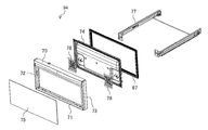
- FIG. 13 is an exploded perspective view showing the configuration of freezer compartment door 94 of refrigerator 100 according to Embodiment 1 of the present invention.
- the double door and the drawer door of the refrigerator 100 will be described.
- all the doors from the ice making compartment 2 to the vegetable compartment 5 are drawer type doors, but since the components are almost the same, the structure of the freezing compartment door 94 will be described here.
- the refrigerating compartment left door 6 and the refrigerating compartment right door 7 are composed of resin caps 70, 71, 72 and 73 on the upper, lower, left and right sides, the inner surface of the door is composed of a resin inner plate 74, and the door surface is made of glass. It is composed of a door surface panel 75.
- the inside of the refrigerating compartment left door 6 and the refrigerating compartment right door 7 is filled with urethane foam insulation 10.
- a partition plate 8 for closing the space between the refrigerating compartment left door 6 and the refrigerating compartment right door 7 is hinge-fixed to the side surface of the inner plate 74 on the center side so as to rotate when the door is opened and closed.
- the refrigerating room left door 6 is provided with a setting operation section 20 that allows the user to operate the temperature setting of each storage room and the mode setting.
- the partition plate 8 and the setting operation unit 20 may be provided on the refrigerating compartment right door 7.
- the cap 71 on the lower side of the refrigerating compartment left door 6 and the lower side of the refrigerating compartment right door 7 are provided with concave portions 71a, respectively, which serve as door handle portions.
- the door surface panel 75 may be a sheet metal panel, in which case the left and right caps 72, 73 may be omitted.
- the freezer compartment door 94 has a structure similar to that of the double-door type door with respect to the upper, lower, left, right, and front surfaces, but a holding member 78 for mounting a frame 77 on which the upper case 27 and the lower case 28 are mounted is provided inside the inner plate 74. And the frame 77 is fixed by screws. It should be noted that the door handle portion 69 may be provided either above or below the freezer compartment door 94, but in the first embodiment, it is provided on the upper cap 70.
- the double doors and drawer doors of the refrigerator 100 according to the first embodiment are configured as described above.
- heat from the dew condensation prevention pipe 47 provided in each of the compartment partitions 21, 26, 31 is conducted through the gasket 67 and the caps 70, 71. Can be warmed by.
- the heat from the inner plate 74 facing the inside of the refrigerator is conducted to be cooled. Therefore, the temperature of the door handle 69 is determined by a complicated thermal effect.
- FIG. 14 is a longitudinal section (a sectional view taken along the line DD in FIG. 1) showing a state where the vacuum heat insulating material 76 is provided on the freezer compartment door 94 shown in FIG. Although the urethane foam insulation 10 is filled inside the freezer compartment door 94, a vacuum insulation 76 may be provided between the door handle 69 and the inner plate 74 as shown in FIG. .. Since the thermal conductivity of the vacuum heat insulating material 76 is about 1/10 of the heat conductivity of the urethane foam heat insulating material 10, the amount of heat entering the inner plate 74 from the door handle 69 is reduced, and the temperature of the door handle 69 is reduced. It is effective to raise.
- FIG. 15 is a first block diagram of refrigerant circuit 102 of refrigerator 100 according to Embodiment 1 of the present invention.
- FIG. 15 shows the refrigerant circuit 102 in a normal flow state.
- the flow of the refrigerant in the normal flow state in the refrigerant circuit 102 is as shown by an arrow.
- the refrigerant discharged from the compressor 36 first enters the flow path switching device 42 and reaches the condensation system piping.
- the condensing system piping the machine room condenser 43, the left side condensing piping 44, the ceiling condensing piping 45, the back condensing piping 46, the right side condensing piping 54, and the dew prevention piping 47 flow in this order, and the flow path switching device 42.
- the left side condensing pipe 44, the ceiling condensing pipe 45, the rear condensing pipe 46, and the right side condensing pipe 54 are collectively referred to as a surface condensing pipe.
- FIG. 16 is a second block diagram of refrigerant circuit 102 of refrigerator 100 according to Embodiment 1 of the present invention.
- FIG. 15 shows the refrigerant circuit 102 in the reverse flow state. The flow of the refrigerant in the reverse flow state in the refrigerant circuit 102 is as shown by an arrow.
- the refrigerant discharged from the compressor 36 first enters the flow path switching device 42 and reaches the condensation system piping.
- the dew condensation prevention piping 47, the right side condensing piping 54, the back side condensing piping 46, the ceiling condensing piping 45, the left side condensing piping 44, and the machine room condenser 43 flow in this order, and the flow path switching device 42.
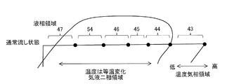
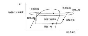
- FIG. 17 is a Mollier diagram of the refrigerant circuit 102 of the refrigerator 100 according to Embodiment 1 of the present invention in a normal flow state and a reverse flow state.
- FIG. 18 is an enlarged view of the condensing process of FIG. 17 in the normal flow state.
- FIG. 19 is an enlarged view of the condensation process of FIG. 17 in the reverse flow state.
- the state of the refrigerant in the dew condensation preventing pipe 47 is in the latter half of the condensation step, so that it is in a gas-liquid two-phase state to a liquid phase state.
- the reverse flow state the process is subsequent to the compression process by the compressor 36. Therefore, the inlet of the dew condensation preventing pipe 47 is in a gas phase state, and the outlet is in a gas-liquid two-phase state.
- the temperature of the refrigerant is higher toward the right side in the vapor phase region and isotherm changes in the gas-liquid two-phase region. Is higher than in the normal sink condition. Therefore, in the reverse flow state, it is possible to raise the temperature in the cabinet flange portion 55 and the door handle portion 69 as compared with the normal flow state.
- the point of the first embodiment is to use the sensible heat change on the vapor phase side for the temperature of the dew condensation prevention pipe 47. That is, the sensible heat change on the gas phase side can be used by controlling the flow path switching device 42 so that the inlet of the dew condensation preventing pipe 47 can be connected next to the compressor 36. Therefore, by connecting the pipes as in the first embodiment, it is possible to allow the high-temperature refrigerant to flow into the dew condensation prevention pipe 47, thereby improving the dew condensation resistance.
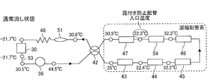
- FIG. 20 is a diagram showing actual machine temperature data of each part of the refrigerant circuit 102 in the normal flow state of the refrigerator 100 according to the first embodiment of the present invention.
- 21 is a figure which shows the actual machine temperature data of each part of the refrigerant circuit 102 in the backflow state of the refrigerator 100 which concerns on Embodiment 1 of this invention.
- FIG. 22 is the figure which compared the temperature of each part of the refrigerator 100 which concerns on Embodiment 1 of this invention in the normal flow state and the reverse flow state.
- the data shown in FIGS. 20 to 22 are actual measurement data when the flow path switching device 42 is attached to a refrigerator having a rated internal volume of 500 L and the refrigerator has an ambient temperature of 30° C. and a relative humidity of 50%. It is measured by switching the flow of the refrigerant by the path switching device 42 and fixing it in the normal flow state and the reverse flow state, respectively.
- the temperature of each part shown in FIG. 22 is a measurement of the pipe surface temperature of the refrigerator 100, and the inlet temperature of the dew condensation preventing pipe 47 in the reverse flow state is 32.3° C. to 35.2 as compared with the normal flow state. It can be seen that the temperature rises at about 3K. Since the freezing room temperature is the lowest in the room of the refrigerator 100, when the temperature around the freezing room is confirmed, the partition plate surface temperature and the freezing room of the room partitioning part 26 that separates the ice making room 2 and the small freezing room 3 from the freezing room 4 The surface temperature of the handle is also higher in the backflow state.
- the power consumption in the reverse flow state is about 3% higher than that in the normal flow state, but this causes the temperature of the dew condensation prevention pipe 47 to be high, and a large amount of heat enters from the upper and lower ends of the partition surface sheet metal. It is because it has become.
- FIG. 23 is a diagram showing the temperature of the door handle 69 with respect to the relative humidity of the refrigerator 100 according to Embodiment 1 of the present invention.
- the horizontal axis in FIG. 23 represents relative humidity and the vertical axis represents temperature.
- the solid line curve shows the dew point temperature when the ambient temperature of the refrigerator is 30°C.
- the temperature of the door handle portion 69 in the normal flow state is indicated by the first broken line, and the temperature in the reverse flow state is indicated by the second broken line.
- the temperature of the door handle 69 is higher than the dew point temperature until the relative humidity is around 80%, but when the relative humidity is higher than that, the temperature of the door handle 69 is dew point.
- the temperature inside the refrigerator rises due to the user opening and closing the door, and the temperature of the door handle 69 rises accordingly. Therefore, when the relative humidity is around 80%, dew does not necessarily adhere, but the risk of dew increases.
- the temperature of the dew condensation prevention pipe 47 rises, so that the temperature of the door handle 69 also rises, and the temperature of the door handle 69 does not fall below the dew point temperature until the relative humidity is around 90%.
- the control device 9 changes the time ratio between the normal flow state and the reverse flow state (this is referred to as a flow path switching rate) according to the relative humidity detected by the ambient humidity sensor 35.
- the flow path switching device 42 is switched to.
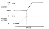
- FIG. 24 is a 1st figure which shows the flow-path switching rate with respect to the relative humidity of the refrigerator 100 which concerns on Embodiment 1 of this invention.
- FIG. 25 is a 2nd figure which shows the flow-path switching rate with respect to relative humidity of the refrigerator 100 which concerns on Embodiment 1 of this invention.
- the normal flow state is the flow path switching rate of 0%
- the reverse flow state is the flow path switching rate of 100%
- FIG. 24 shows the relative humidity on the horizontal axis and the flow path switching rate on the vertical axis.
- the control device 9 when detecting the relative humidity of 80%, the control device 9 sets 7 minutes of the 10-minute operation to the normal flow state and the remaining 3 minutes to the reverse flow state.
- the flow path switching rate at this time is 30%.
- the dew point temperature is lower than the temperature of the door handle 69 up to a relative humidity of 75%, so that the refrigerator is set in a normal sink state (flow path switching rate is 0%).
- the flow path switching rate is increased from the point where the relative humidity of the surroundings is higher than 75% and the dew point temperature exceeds the temperature of the door handle 69, and the flow path switching rate of 100% is detected when the relative humidity of 90% is detected.
- the flow path switching device 42 is controlled so as to always be in a reverse flow state.
- the flow path switching rate may be set stepwise so that the temperature of the handle 69 is always higher than the dew point temperature. At this time, such setting of the flow path switching rate is set separately for each ambient temperature stage.
- the ambient temperature stage is a stepwise capture of the ambient temperature of the refrigerator 100, such as ambient temperature of -10°C, 10°C-20°C, 20°C-30°C, 30°C-. Then, at each ambient temperature stage, the setting of the flow path switching rate with respect to the relative humidity as shown in FIGS. 24 and 25 is programmed in the control device 9. By doing so, it is possible to automatically change the flow path switching rate according to the ambient temperature and the relative humidity, and it is possible to provide the refrigerator 100 in which dew condensation does not occur even at high temperature and high humidity.
- the temperature of the dew condensation prevention pipe 47 can be greatly increased by the above control, so that it is not necessary to attach an aluminum tape or the like, and the cost is reduced. You can also
- FIG. 26 is a vertical cross-sectional view (a cross-sectional view taken along the line EE in FIG. 1) in which the injection hole 98 is formed in the partition 31 between the chambers shown in FIG.
- the space surrounded by the surface partition plate 61 and the partition body 64 may be filled with the urethane foam heat insulating material 10. Then, as shown in FIG. 26, when foaming the inside of the partition body 64 with the urethane foam heat insulating material 10, the heat insulating material 10 is wrapped around the space surrounded by the surface partition plate 61 and the partition body 64. An injection hole 98 is formed on the body 64 side.
- an air vent hole 97 is formed in the front part of the lower surface of the partition body 64 (the lower surface of this space) so that air is not accumulated during foaming, and the surface is covered with the sealing material 60 after foaming.
- the refrigerator 100 includes the compressor 36, the flow path switching device 42, the machine room condenser 43, the surface condensation pipe, the dew condensation prevention pipe 47, the decompression device, and the cooler 30.
- the refrigerant circuit 102 in which the refrigerant circulates, the ambient humidity sensor 35 that detects the relative humidity of the surroundings, and the control device 9 that controls the flow path switching device 42 are provided, and the control device 9 detects the ambient humidity sensor 35.
- the relative humidity is smaller than the preset reference value
- the normal flow state in which the refrigerant flows in the order of the compressor 36, the flow path switching device 42, the machine room condenser 43, the surface condensation pipe, and the dew condensation prevention pipe 47 is set.
- the compressor 36, the flow path switching device 42, the dew condensation prevention pipe 47, the surface condensation pipe, the machine room condensation The flow path switching device 42 is switched so that the refrigerant flows backward in the order of the container 43.
- the flow path switching device 42 when the relative humidity detected by the ambient humidity sensor 35 is equal to or higher than the reference value, the flow path switching device 42 is switched to be in the reverse flow state. That is, the sensible heat change on the gas phase side can be used by controlling the flow path switching device 42 so that the inlet of the dew condensation preventing pipe 47 can be connected next to the compressor 36. Therefore, a high temperature refrigerant can be allowed to flow into the dew condensation prevention pipe 47, and the dew condensation resistance can be improved.
- Embodiment 2 the second embodiment of the present invention will be described. However, the description of the same parts as those of the first embodiment will be omitted, and the same or corresponding parts as those of the first embodiment will be designated by the same reference numerals.
- the parts configuration of the refrigerator 100 according to the second embodiment is the same as that of the first embodiment.
- the refrigerator 100 according to the second embodiment shifts the flow path switching rate according to the temperature setting of the freezer compartment 4 selected by the user.
- the temperature of the freezer compartment 4 is set to a high temperature (about ⁇ 20° C.), an intermediate temperature (about ⁇ 18° C.), by the setting operation unit 20 provided on the refrigerating compartment left door 6.
- the user can set a low temperature (about -16°C).
- the flow path switching rate is shifted in the form of a broken line when the high temperature of the freezer compartment 4 is set, a solid line when the medium temperature is set, and a one-dot chain line when the weak temperature is set, and is low if the set temperature of the freezer compartment 4 is low.
- the flow path switching rate may be shifted according to the set temperature not only in the freezing room 4 but also in other storage rooms.
- the storage room in which the temperature is set to be the lowest in the refrigerator 100 is the freezing room 4, and the shift amount of the flow path switching rate according to the setting temperature in the other storage room depends on the setting temperature of the freezing room 4. It is preferable to set the flow path switching rate smaller than the shift amount. Then, as the flow path switching rate according to the set temperature of the freezer compartment 4, the highest flow path switching rate may be selected as compared with the flow path switching rates set in other storage chambers.
- Embodiment 3 Hereinafter, the third embodiment of the present invention will be described. However, the description of the same parts as those of the first and second embodiments will be omitted, and the same or corresponding parts as those of the first and second embodiments will be designated by the same reference numerals. ..
- the refrigerator 100 is equipped with three modes including an automatic mode, an energy saving priority mode, and a dew condensation countermeasure mode, and these modes are the setting operation unit provided in the refrigerating room left door 6.
- these modes are the setting operation unit provided in the refrigerating room left door 6.
- the environment in which the refrigerator 100 is installed such as the ambient temperature and the relative humidity, is greatly affected by the heat insulation and airtightness of the house, the place where it is installed, the influence of air conditioners such as air conditioners, and the replacement of air by opening windows. It depends. Depending on the environment, even if the temperature is high outside the house, the temperature and humidity are not so high inside the house, or conversely, the temperature is high like the outside of the house.
- FIG. 28 is a figure which shows the flow-path switching rate with respect to the relative humidity of the refrigerator 100 which concerns on Embodiment 3 of this invention.
- the user can select the mode according to the installation environment of the refrigerator 100, and the flow path switching rate is shifted according to the mode as shown in FIG. 28.
- the solid line is the automatic mode, and the flow path switching rate is automatically set by the control device 9 according to the ambient temperature and the relative humidity of the refrigerator 100.
- the alternate long and short dash line is the energy saving priority mode, which is the mode in which the flow path switching rate is set lower than that in the automatic mode, and the increase in the power consumption is suppressed by increasing the time ratio in the normal running state.
- This energy saving priority mode is suitable for the environment in which the refrigerator 100 is installed, where the ambient temperature and the relative humidity are relatively low.
- the broken line is a dew condensation countermeasure mode, which is a mode in which the flow path switching rate is set higher than that in the automatic mode, and the dew condensation is suppressed.
- a second energy saving priority mode that is an energy saving priority mode fixed to a normal sink state and a second dew condensation countermeasure mode that is a dew condensation countermeasure mode fixed to a reverse flow state are mounted. Good.
- the temperature of the freezer compartment 4 may be increased by about 1K along with the setting of the dew condensation countermeasure mode. This is because the risk of dew condensation is the highest in the storage room of the refrigerator 100 around the freezing room 4 having the lowest temperature.
- FIG. 29 is a first diagram showing a time transition of the rotation speed of the compressor 36 and the like in the automatic mode of the refrigerator 100 according to the third embodiment of the present invention.
- FIG. 30 is a first diagram showing a time transition of the rotation speed of the compressor 36 and the like in the dew condensation countermeasure mode of the refrigerator 100 according to the third embodiment of the present invention.
- the difference between the ON point and the OFF point of the compressor 36 shown by the white arrow in FIG. 30, that is, the differential is made smaller than the differential in the automatic mode shown in FIG. 29. Good.
- ON/OFF of the compressor 36 is controlled by using a freezer compartment temperature sensor 39 installed on the inner side of the freezer compartment 4. Specifically, the control device 9 operates the compressor 36 when the freezer compartment temperature sensor 39 rises to the ON point, and stops the compressor 36 when it cools to the OFF point.
- the difference between the ON point and the OFF point of the compressor 36 in the dew condensation countermeasure mode is made smaller than that in the automatic mode so that the differential becomes smaller in the dew condensation countermeasure mode than in the automatic mode.
- the stop time of the compressor 36 can be shortened, and the time during which the refrigerant does not flow in the dew condensation preventing pipe 47 can be shortened. Therefore, the temperature decrease of the dew condensation prevention pipe 47 can be suppressed to a small level.
- the rotation speed of the compressor 36 during operation is the same as V1rps, the temperature of the dew condensation prevention pipe 47 during operation does not change between the dew condensation countermeasure mode and the automatic operation mode. Therefore, the average temperature of the door handle 69 and the like tends to rise.
- FIG. 31 is a second diagram showing a time transition of the rotation speed of the compressor 36 and the like in the automatic mode of the refrigerator 100 according to the third embodiment of the present invention.
- FIG. 32 is a second diagram showing a time transition of the rotation speed of the compressor 36 and the like in the dew condensation countermeasure mode of the refrigerator 100 according to the third embodiment of the present invention.
- the baffle 40 of the refrigerating compartment damper device 19 is opened and the internal fan 23 is operated while the compressor 36 is stopped to operate the refrigerating compartment. 1 may be cooled.
- the return air of the refrigerating compartment 1 comes in, so that the temperature rise of the cooler 30 while the compressor 36 is stopped becomes faster.
- cold air having a relatively high temperature flows into the freezing compartment 4 to quickly raise the temperature of the freezing compartment temperature sensor 39, and the ON point of the compressor 36 quickly reaches the ON point. You will arrive.
- the stop time of the compressor 36 can be shortened, the time during which the refrigerant does not flow in the dew condensation prevention pipe 47 can be shortened, and the temperature decrease of the dew condensation prevention pipe 47 can be suppressed to a small level. Further, since the rotation speed of the compressor 36 during operation is the same as V1rps, the temperature of the dew condensation prevention pipe 47 during operation does not change between the dew condensation countermeasure mode and the automatic operation mode. Therefore, the average temperature of the door handle 69 and the like tends to rise.
- an expansion device 79 is provided between the dew condensation prevention pipe 47 and the right side condensing pipe 54 for the purpose of lowering the temperature of the dew condensation prevention pipe 47.
- FIG. 33 is a block diagram of the refrigerant circuit 103 of the refrigerator 100 according to Embodiment 4 of the present invention.
- 34 is a figure which shows the structure of the electromagnetic expansion valve 80 used for the refrigerator 100 which concerns on Embodiment 4 of this invention.
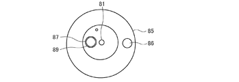
- FIG. 35 is a diagram showing the position of the valve body 84 in the normal flow state of the electromagnetic expansion valve 80 shown in FIG.
- FIG. 36 is a diagram showing the position of the valve element 84 in the reverse flow state of the electromagnetic expansion valve 80 shown in FIG. 34.
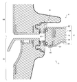
- An electromagnetic expansion valve 80 shown in FIG. 34 is used as the expansion device 79 used in the refrigerant circuit 103 shown in FIG.
- the electromagnetic expansion valve 80 is a valve that is integrally fixed to the resin rotor portion 83 and the shaft 81 inside the coil portion 82 according to an instruction from the control device 9 and has a thin hole 88 and a thick hole 89.
- the body 84 is rotated to switch the flow path.
- a valve seat 85 is provided below the valve element 84, and an inlet pipe portion 86 and an outlet pipe portion 87 are connected to the valve seat 85.
- the electromagnetic expansion valve 80 rotates in the normal flow state by rotating the valve body 84 so that the small hole 88 having a small hole diameter is connected to the outlet pipe portion 87, depressurizes the refrigerant, and reduces the refrigerant flow rate. The refrigerant temperature before entering the anti-sticking pipe 47 is lowered.
- the valve body 84 rotates so that the thick hole 89 having a large hole diameter is connected to the outlet pipe portion 87.
- the electromagnetic expansion valve 80 operates together with the flow path switching of the flow path switching device 42, and in the normal flow state, the flow path is throttled by the electromagnetic expansion valve 80 on the upstream side of the dew condensation prevention pipe 47. As a result, the temperature of the dew condensation prevention pipe 47 decreases.
- FIG. 37 is a first Mollier diagram in the normal flow state of the refrigerant circuit 102 of the refrigerator 100 according to Embodiment 4 of the present invention.
- FIG. 38 is a second Mollier diagram in the normal flow state of the refrigerant circuit 102 of the refrigerator 100 according to the fourth embodiment of the present invention.
- FIG. 39 is a Mollier diagram in the reverse flow state of the refrigerant circuit 102 of the refrigerator 100 according to Embodiment 4 of the present invention.
- FIG. 40 is an enlarged view of the condensation process of FIG. 37.
- 41 is an enlarged view of the condensation step of FIG. 38.
- 42 is an enlarged view of the condensing process of FIG. 39.
- the valve body 84 of the electromagnetic expansion valve 80 When the relative humidity detected by the ambient humidity sensor 35 is lower than a predetermined threshold value, the valve body 84 of the electromagnetic expansion valve 80 is moved at an hourly rate. Therefore, the Mollier diagram in the normal sinking state has two patterns, that is, when the thin hole 88 of the valve body 84 shown in FIGS. 37 and 40 is used and when the thick hole 89 of the valve body 84 shown in FIGS. 38 and 41 is used. Become. Further, the Mollier diagram in the reverse flow state is as shown in FIGS. 39 and 42 because the valve body 84 is fixed to the thick hole 89.
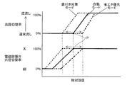
- FIG. 43 is a first diagram showing flow channel switching rates and hole diameter switching rates with respect to relative humidity of refrigerator 100 according to Embodiment 4 of the present invention.
- the flow path switching rate and the hole diameter switching rate of the electromagnetic expansion valve 80 with respect to the relative humidity will be described with reference to FIG.
- the time ratio between the time when the thick hole 89 of the valve body 84 of the electromagnetic expansion valve 80 is used and the time when the thin hole 88 is used is defined as the hole diameter switching ratio, and 0 when the thin hole 88 of the valve body 84 of the electromagnetic expansion valve 80 is used.
- the temperature of the door handle 69 is relatively high even when the flow path switching device 42 is kept in the normal flow state, and there is still room for temperature at a relative humidity of 50%. Therefore, when the relative humidity detected by the ambient humidity sensor 35 is lower than a predetermined value, the valve body 84 of the electromagnetic expansion valve 80 is switched between the thick hole 89 and the thin hole 88 at a time ratio in the normal flow state.
- the valve body 84 of the electromagnetic expansion valve 80 is fixed by the thick hole 89 so that the valve 84 does not expand thereafter, and the refrigerant flows backward.
- FIG. 44 is a second diagram showing the flow channel switching rate and the hole diameter switching rate with respect to the relative humidity of refrigerator 100 according to Embodiment 4 of the present invention. Further, the flow path switching rate and the hole diameter switching rate may be set by combining the energy saving priority mode and the dew condensation countermeasure mode described above. An example is shown in FIG. 44, and the point P of a predetermined relative humidity at which the normal flow state is fixed is shifted with the automatic mode as a solid line. In the energy saving priority mode (dashed line), the point P is raised, that is, shifted to the high humidity side (right side in FIG. 44), and in the dew condensation countermeasure mode (dashed line), the point P is lowered, that is, the low humidity side (see FIG. (On the left side of 44).
Abstract
This refrigerator is provided with: a refrigerant circuit which is provided with a compressor, a flow passage switching device, a machine room condenser, a surface condensing tube, a dew condensation preventing tube, a depressurizing device, and a cooler, and through which a refrigerant circulates; a ambient humidity sensor for detecting the ambient relative humidity; and a control device for controlling the flow passage switching device. When the relative humidity detected by the ambient humidity sensor is lower than a preset reference value, the control device switches the flow passage switching device such that a refrigerant flows in a normal flow state in which the refrigerant flows through in the order of the compressor, the flow passage switching device, the machine room condenser, the surface condensing tube, and the dew condensation preventing tube; and when the relative humidity detected by the ambient humidity sensor is no less than the reference value, the control device switches the flow passage switching device such that a refrigerant flows in a reverse flow state in which the refrigerant flows through in the reverse order of the compressor, the flow passage switching device, the dew condensation preventing tube, the surface condensing tube, and the machine room condenser.
Description
本発明は、霜付きを抑制した冷蔵庫に関するものである。
The present invention relates to a refrigerator in which frost is suppressed.
近年、冷蔵庫が設置される環境に合わせて最適な運転を実現させるために、温度センサおよび湿度センサなどが搭載される冷蔵庫が増えてきている。例えば、冷蔵室扉が左右に分割されていて、その冷蔵室扉間の仕切板にヒータなどが設置され、周囲の室温および湿度に合わせてヒータへの通電を時間割合で変化させたりすることで、仕切板の表面温度を調節して省エネルギー性を高めるような冷蔵庫がある。
In recent years, an increasing number of refrigerators are equipped with temperature sensors and humidity sensors in order to realize optimal operation in accordance with the environment in which the refrigerator is installed. For example, the refrigerating compartment door is divided into left and right, a heater is installed on the partition plate between the refrigerating compartment doors, and the energization of the heater can be changed at a time rate according to the ambient room temperature and humidity. There are refrigerators that increase the energy saving by adjusting the surface temperature of the partition plate.
また、冷蔵室扉間の仕切板はヒータなどによる加熱により露付きを防止しているが、冷蔵庫側面およびキャビネットフランジ部においては、凝縮配管および露付き防止配管を配置して露付きを防止している。ここで、一般的にヒータの発熱による電力消費効率は冷媒回路の電力消費効率よりも悪いため、ヒータで発熱させるよりも凝縮配管の熱を利用して冷蔵庫の外郭温度を上昇させる露付き対策を実施することが、冷蔵庫の省エネルギー性改善への近道となる。
The partition plate between the refrigerator compartment doors is protected from dew by heating with a heater, etc., but on the side of the refrigerator and the cabinet flange, condensation pipes and dew prevention pipes are placed to prevent dew condensation. There is. Here, in general, the power consumption efficiency due to the heat generation of the heater is lower than the power consumption efficiency of the refrigerant circuit, so a measure against dew condensation that raises the outer temperature of the refrigerator by using the heat of the condensation pipe rather than causing the heater to generate heat is taken. Implementation is a shortcut to improve the energy efficiency of refrigerators.
そこで、従来、凝縮系配管の熱を利用してキャビネットフランジ部および部屋間仕切表面温度を上げる技術が報告されている(例えば、特許文献1および特許文献2参照)。
Therefore, heretofore, there has been reported a technique of increasing the surface temperature of the cabinet flange and the partition wall by utilizing the heat of the condensation system piping (for example, refer to Patent Document 1 and Patent Document 2).
特許文献1では、四方弁を使用してキャビネットフランジ部および部屋間仕切部の表面内に設置される防露パイプの冷媒の流れ順序を切り替える技術が報告されている。これは、使用者が冷蔵庫表面に設置される設定操作部にて防露モードを切り替えることで、冷媒回路の冷媒の流れが変わるものである。具体的には、防露モード「弱」が選択された場合には、冷媒回路の冷媒の流れが、圧縮機→凝縮器→四方弁→放熱パイプ→防露パイプ→四方弁→キャピラリーチューブ→蒸発器→圧縮機の通常流れ状態となる。一方、防露モード「強」が選択された場合には、冷媒回路の流れが、圧縮機→凝縮器→四方弁→防露パイプ→放熱パイプ→四方弁→キャピラリーチューブ→蒸発器→圧縮機の逆流れ状態となり、防露を優先する流れとなる。
Patent Document 1 reports a technology that uses a four-way valve to switch the flow order of the refrigerant in a dew-proof pipe installed in the surfaces of the cabinet flange and the room partition. This is because the flow of the refrigerant in the refrigerant circuit changes when the user switches the dew-proof mode on the setting operation unit installed on the surface of the refrigerator. Specifically, when the dew prevention mode “weak” is selected, the flow of refrigerant in the refrigerant circuit is: compressor → condenser → four-way valve → radiating pipe → dew-proof pipe → four-way valve → capillary tube → evaporation The normal flow condition of the compressor → the compressor is achieved. On the other hand, when the dew-proof mode “strong” is selected, the flow in the refrigerant circuit is as follows: compressor→condenser→four-way valve→dew-proof pipe→heat radiation pipe→four-way valve→capillary tube→evaporator→compressor. This is the reverse flow state, and the flow prioritizes dew prevention.
また、特許文献2では、四方弁を使用して箱体の開口縁に設けた結露抑制器の冷媒流れ方向を逆にする技術が報告されている。これは、減圧部による減圧量を大きくしたり、機械室ファンを高速運転させたりした場合に、結露抑制器の配管内を占める液比率が高まる。そのため、温度低下が大きくなり、減圧部に流入する冷媒の比エンタルピが低下するので、熱交換部で熱交換する冷媒のエンタルピ差を大きくすることができ、省エネルギー性を向上させることができるものである。
In addition, Patent Document 2 reports a technique in which a four-way valve is used to reverse the refrigerant flow direction of a dew condensation suppressor provided at the opening edge of the box body. This is because when the amount of decompression by the decompression unit is increased or the machine room fan is operated at high speed, the ratio of the liquid occupying the pipe of the dew condensation suppressor increases. Therefore, the temperature decrease becomes large and the specific enthalpy of the refrigerant flowing into the pressure reducing section decreases, so that the enthalpy difference of the refrigerant that exchanges heat in the heat exchanging section can be increased, and the energy saving property can be improved. is there.
特許文献1は、防露モードの強弱によって放熱パイプと防露パイプとで冷媒が流れる順序を入れ替えるようにしている。しかしながら、凝縮器の下流側に四方弁が設けられているため、圧縮機の吐出側に接続されている凝縮器の下流側での順序の入れ替えであり、凝縮器で冷媒の温度を大きく下げた後で防露パイプに冷媒を入れる形となる。そのため、露付き耐力の改善に大きな効果は得られない。これは、モリエル線図からみればわかることであるが、凝縮器を出たあとの冷媒は気液二相領域に入り、この領域では冷媒の温度は一定であるためである。また、各室仕切表面においては温度改善が見られる程度であるが、扉表面の温度を改善するまでのものではなく、露付き耐力改善の効果も小さいと推定される。
In Patent Document 1, the order in which the refrigerant flows in the heat radiating pipe and the dew proof pipe is switched depending on the strength of the dew proof mode. However, since the four-way valve is provided on the downstream side of the condenser, the order is changed on the downstream side of the condenser connected to the discharge side of the compressor, and the temperature of the refrigerant is greatly reduced in the condenser. After that, the refrigerant is put in the dew-proof pipe. Therefore, a great effect cannot be obtained in improving the proof strength against dew. This can be understood from the Mollier diagram, because the refrigerant after leaving the condenser enters the gas-liquid two-phase region, and the temperature of the refrigerant is constant in this region. Further, although the temperature is improved on the surface of each room partition, it is estimated that the temperature does not improve until the temperature of the door surface is improved, and the effect of improving the dew resistance is small.
また、特許文献2は、四方弁を使い箱体前面開口縁のキャビネットフランジ部に取り付けられる露付き防止配管(結露抑制器)内を流れる向きを逆向きに変更する。そして、温度の低い液冷媒が多く存在する部位を冷蔵庫のどの部屋の周りに流すかで省エネルギー性を高めるものであるが、露付き耐力の改善については言及していない。また、箱体の機械室、側面、天井面、および、背面に設けた放熱器(凝縮器)後の流し方を変えるだけである。そして、箱体の前面開口縁のキャビネットフランジにおいて、どこの部位の温度が高くなり、どこの部位の温度が低くなるかといった温度のバランスが変わるだけであると推測される。そのため、省エネルギー性の改善には効果があるが露付き耐力の改善には効果がない。
Also, in Patent Document 2, the direction of flow in the dew condensation prevention pipe (condensation suppressor) attached to the cabinet flange portion of the front opening edge of the box body is changed to a reverse direction by using a four-way valve. Then, although the energy saving property is enhanced depending on around which room of the refrigerator the part where a large amount of liquid refrigerant having a low temperature is present is flown, no mention is made of improvement of dew resistance. Further, it is only necessary to change the flow method after the radiator (condenser) provided on the machine room, the side surface, the ceiling surface, and the back surface of the box body. It is presumed that the balance of the temperature is changed only in which part of the cabinet flange on the front opening edge of the box body has a higher temperature and which part has a lower temperature. Therefore, it is effective in improving the energy saving property, but is not effective in improving the dew resistance.
つまり、露付き性の改善に関して、特許文献1では、露付き防止配管の温度がそれほど高くならず、特許文献2では、露付き防止配管の温度を下げられるが上げられない。そのため、両方ともに、通常流れではモリエル線図の気液二相または液相(過冷却域)を使用して冷蔵庫前面開口縁のキャビネットフランジ部に設置される露付き防止配管の温度を下げて省エネルギー化を図っている。また、露付き対応時は流れを変えて露付き防止配管内の液相の度合いを減らすようにしている。しかしながら、露付き防止配管内は、気液二相レベルの温度にしか上げられなく、高温多湿、たとえば冷蔵庫周囲外気温度30℃以上、かつ、周囲相対湿度90%以上ではいっそうの露付き耐力改善は望めない。
That is, regarding the improvement of the dew condensation property, in Patent Document 1, the temperature of the dew condensation prevention pipe is not so high, and in Patent Document 2, the temperature of the dew condensation prevention pipe can be lowered but cannot be increased. Therefore, in both cases, in the normal flow, the vapor-liquid two-phase or liquid-phase (supercooling region) of the Mollier diagram is used to reduce the temperature of the dew condensation prevention pipe installed on the cabinet flange part at the opening edge of the front of the refrigerator to save energy. I am trying to make it. When dealing with dew condensation, the flow is changed to reduce the degree of liquid phase in the dew condensation prevention pipe. However, the inside of the dew-prevention pipe can be raised only to the temperature of the gas-liquid two-phase level, and when the temperature is high and high, for example, the ambient temperature of the refrigerator is 30°C or higher, and the relative relative humidity is 90% or higher, further improvement of the dew-proof strength is not possible. I can't hope.
以上のように、特許文献1および特許文献2では、露付き耐力改善にコストがかかっている割には、高温多湿時に露付き耐力をあまり改善できないという課題があった。
As described above, in Patent Document 1 and Patent Document 2, there is a problem that the dew proof stress cannot be improved so much at high temperature and high humidity, although the cost for improving the dew proof stress is high.
本発明は、以上のような課題を解決するためになされたもので、高温多湿時に露付き耐力を改善することができる冷蔵庫を提供することを目的としている。
The present invention has been made to solve the above problems, and an object thereof is to provide a refrigerator capable of improving the resistance to dew condensation when the temperature and humidity are high.
本発明に係る冷蔵庫は、圧縮機、流路切替装置、機械室凝縮器、面凝縮配管、露付き防止配管、減圧装置、および、冷却器を備え、冷媒が循環する冷媒回路と、周囲の相対湿度を検知する周囲湿度センサと、前記流路切替装置を制御する制御装置と、を備え、前記制御装置は、前記周囲湿度センサで検知した相対湿度があらかじめ設定された基準値よりも小さい場合は、前記圧縮機、前記流路切替装置、前記機械室凝縮器、前記面凝縮配管、前記露付き防止配管の順に冷媒が流れる通常流し状態となるように前記流路切替装置を切り替え、前記周囲湿度センサで検知した相対湿度が前記基準値以上の場合は、前記圧縮機、前記流路切替装置、前記露付き防止配管、前記面凝縮配管、前記機械室凝縮器の順に冷媒が流れる逆流し状態となるように前記流路切替装置を切り替えるものである。
A refrigerator according to the present invention includes a compressor, a flow path switching device, a machine room condenser, a surface condensation pipe, a dew condensation preventing pipe, a decompression device, and a cooler, and a refrigerant circuit in which a refrigerant circulates and a surrounding relative. An ambient humidity sensor that detects humidity, and a control device that controls the flow path switching device are provided, and the control device, when the relative humidity detected by the ambient humidity sensor is smaller than a preset reference value, , The compressor, the flow path switching device, the machine room condenser, the surface condensation pipe, the dew condensation prevention pipe to switch the flow path switching device so as to be a normal flowing state in which the refrigerant flows, the ambient humidity When the relative humidity detected by the sensor is equal to or higher than the reference value, the compressor, the flow path switching device, the dew condensation prevention pipe, the surface condensation pipe, the backflow state in which the refrigerant flows in order of the machine room condenser and The flow path switching device is switched so that
本発明に係る冷蔵庫によれば、周囲湿度センサで検知した相対湿度が基準値以上の場合は、逆流し状態となるように流路切替装置を切り替えている。つまり、露付き防止配管の入口を圧縮機の次に接続できるように流路切替装置を制御することで、気相側の顕熱変化を利用できる。そのため、高い温度の冷媒を露付き防止配管へ流入させることが可能となり、露付き耐力を改善することができる。
According to the refrigerator of the present invention, when the relative humidity detected by the ambient humidity sensor is equal to or higher than the reference value, the flow path switching device is switched so as to be in the reverse flow state. That is, the sensible heat change on the gas phase side can be used by controlling the flow path switching device so that the inlet of the dew condensation preventing pipe can be connected next to the compressor. Therefore, a high temperature refrigerant can be made to flow into the dew condensation prevention pipe, and the dew condensation resistance can be improved.
以下、本発明の実施の形態を図面に基づいて説明する。なお、以下に説明する実施の形態によって本発明が限定されるものではない。また、以下の図面では各構成部材の大きさの関係が実際のものとは異なる場合がある。
Hereinafter, an embodiment of the present invention will be described with reference to the drawings. The present invention is not limited to the embodiments described below. Further, in the following drawings, the size relationship of each component may be different from the actual one.
実施の形態1.
図1は、本発明の実施の形態1に係る冷蔵庫100の正面模式図である。図2は、図1のA-A断面矢視図である。
以下、本実施の形態1に係る冷蔵庫100の構成について説明する。以下の説明において、理解を容易にするために方向を表す用語、例えば「上」、「下」、「右」、「左」、「前」、「後」など、を適宜用いるが、これは説明のためのものであって、これらの用語は本願発明を限定するものではない。また、本実施の形態1では、冷蔵庫100を正面視した状態において、「上」、「下」、「右」、「左」、「前」、「後」などを使用する。Embodiment 1.
1 is a schematic front view of arefrigerator 100 according to Embodiment 1 of the present invention. FIG. 2 is a sectional view taken along the line AA of FIG.
Hereinafter, the configuration of therefrigerator 100 according to the first embodiment will be described. In the following description, for easy understanding, terms indicating directions are appropriately used, such as “upper”, “lower”, “right”, “left”, “front”, “rear”, etc. These terms are for the purpose of description and do not limit the present invention. Further, in the first embodiment, “top”, “bottom”, “right”, “left”, “front”, “rear”, etc. are used when the refrigerator 100 is viewed from the front.
図1は、本発明の実施の形態1に係る冷蔵庫100の正面模式図である。図2は、図1のA-A断面矢視図である。
以下、本実施の形態1に係る冷蔵庫100の構成について説明する。以下の説明において、理解を容易にするために方向を表す用語、例えば「上」、「下」、「右」、「左」、「前」、「後」など、を適宜用いるが、これは説明のためのものであって、これらの用語は本願発明を限定するものではない。また、本実施の形態1では、冷蔵庫100を正面視した状態において、「上」、「下」、「右」、「左」、「前」、「後」などを使用する。
1 is a schematic front view of a
Hereinafter, the configuration of the
図1および図2に示すように、本実施の形態1に係る冷蔵庫100は、複数の貯蔵室を備えており、具体的には、冷蔵室1と、製氷室2と、小型冷凍室3と、冷凍室4と、野菜室5とを備えている。
As shown in FIGS. 1 and 2, the refrigerator 100 according to the first embodiment includes a plurality of storage chambers, and specifically, a refrigerating chamber 1, an ice making chamber 2, and a small freezing chamber 3. A freezer compartment 4 and a vegetable compartment 5 are provided.
冷蔵室1は、冷蔵庫100の最上段に設けられており、前面開口部が2枚の観音開き式扉で開閉自在に閉塞されている。この2枚の観音開き式扉は、冷蔵室左扉6と冷蔵室右扉7とで構成されており、冷蔵室左扉6と冷蔵室右扉7との間には、その間からの外気の浸入を防ぐ仕切板8が設けられている。
The refrigerating compartment 1 is provided at the top of the refrigerator 100, and the front opening is closed by two double doors that can be opened and closed. The two doors that open in a double door are composed of a refrigerating compartment left door 6 and a refrigerating compartment right door 7. Between the refrigerating compartment left door 6 and the refrigerating compartment right door 7, outside air enters between them. A partition plate 8 for preventing the above is provided.
冷蔵室1の下方には、引き出し式扉である製氷室扉92および小型冷凍室扉93を引き出すと貯蔵室が使用者側に引き出される製氷室2および小型冷凍室3が並列に配置されている。また、冷蔵庫100の最下段には野菜室5が設けられており、野菜室5の上には冷凍室4が設けられている。この冷凍室4は、左右に並列に配置された製氷室2および小型冷凍室3の下方で、かつ、野菜室5の上方に設けられている。これら冷凍室4および野菜室5も、引き出し式扉である冷凍室扉94および野菜室扉95を引き出すと貯蔵室が使用者側に引き出される構成となっている。
Below the refrigerating compartment 1, an ice making compartment 2 and a small freezing compartment 3 are arranged in parallel so that the storage compartment is pulled out to the user side when the ice making compartment door 92 and the small freezing compartment door 93 which are drawer type doors are pulled out. .. A vegetable compartment 5 is provided at the bottom of the refrigerator 100, and a freezing compartment 4 is provided above the vegetable compartment 5. The freezer compartment 4 is provided below the ice making compartment 2 and the small freezer compartment 3 arranged in parallel on the left and right sides, and above the vegetable compartment 5. The freezer compartment 4 and the vegetable compartment 5 are also configured such that the storage compartment is pulled out to the user side when the freezer compartment door 94 and the vegetable compartment door 95 which are drawer type doors are pulled out.
なお、各貯蔵室の配置は本実施の形態1に限定されるものではなく、観音開き式扉を備えた構成であれば、各貯蔵室の配置は問わない。また、冷蔵庫100には、周囲温度センサ34および周囲湿度センサ35が搭載されている。周囲温度センサ34は、冷蔵庫100の周囲の温度を検知するものである。周囲湿度センサ35は、冷蔵庫100の周囲の相対湿度を検知するものである。
The arrangement of each storage room is not limited to the first embodiment, and the arrangement of each storage room does not matter as long as it has a double door. Further, the refrigerator 100 is equipped with an ambient temperature sensor 34 and an ambient humidity sensor 35. The ambient temperature sensor 34 detects the ambient temperature of the refrigerator 100. The ambient humidity sensor 35 detects the relative humidity around the refrigerator 100.
なお、周囲温度センサ34および周囲湿度センサ35は、周囲温度および相対湿度を検知できる位置であれば設置場所は問わない。ただし、周囲温度センサ34および周囲湿度センサ35は、冷蔵庫100の運転、たとえば冷蔵庫側面内側に貼り付けられて固定された凝縮パイプ(図示せず)の温度影響などに影響されない位置に設置するのが望ましい。そのため、周囲温度センサ34および周囲湿度センサ35の設置場所は、例えば冷蔵室左扉6の上側ヒンジ部材(図示せず)であれば、その凝縮パイプなどの熱影響を受けないのでよい。
Note that the ambient temperature sensor 34 and the ambient humidity sensor 35 may be installed at any location as long as they can detect the ambient temperature and the relative humidity. However, the ambient temperature sensor 34 and the ambient humidity sensor 35 should be installed at positions that are not affected by the operation of the refrigerator 100, for example, the temperature effect of a condensation pipe (not shown) attached and fixed to the inside of the side surface of the refrigerator. desirable. Therefore, if the ambient temperature sensor 34 and the ambient humidity sensor 35 are installed at, for example, the upper hinge member (not shown) of the refrigerating compartment left door 6, they are not affected by the heat of the condensation pipe or the like.
冷蔵庫100の背面側には、制御装置9が設けられている。この制御装置9は、例えば、専用のハードウェア、またはメモリに格納されるプログラムを実行するCPU(Central Processing Unit、中央処理装置、処理装置、演算装置、マイクロプロセッサ、プロセッサともいう)で構成されている。
A control device 9 is provided on the back side of the refrigerator 100. The control device 9 includes, for example, dedicated hardware or a CPU (Central Processing Unit, central processing unit, processing device, arithmetic device, microprocessor, processor) that executes a program stored in a memory. There is.
冷蔵室1内には、冷蔵室1の温度を検知するための冷蔵室温度センサ38が冷蔵室風路部品15の表面に設置されている。この冷蔵室温度センサ38は、冷蔵室1内の温度をおよそ見られる位置であれば設置位置は問わない。制御装置9は、冷蔵室温度センサ38で検知した冷蔵室1内の温度に基づいて、冷蔵室1への冷気の送風または遮断を、冷蔵室用ダンパー装置19のバッフル40を動作させることで行う。また、この冷蔵室温度センサ38は、温度補償用に冷蔵室1内に設置されたヒータ(図示せず)、および、仕切板8内に設置されたヒータ(図示せず)への通電制御等を行うために用いられる。
In the refrigerating compartment 1, a refrigerating compartment temperature sensor 38 for detecting the temperature of the refrigerating compartment 1 is installed on the surface of the refrigerating compartment air passage part 15. The refrigerating compartment temperature sensor 38 may be installed at any position as long as the temperature inside the refrigerating compartment 1 can be roughly observed. The control device 9 sends or shuts off the cool air to the refrigerating compartment 1 based on the temperature in the refrigerating compartment 1 detected by the refrigerating compartment temperature sensor 38 by operating the baffle 40 of the refrigerating compartment damper device 19. . Further, this refrigerating compartment temperature sensor 38 controls energization to a heater (not shown) installed in the refrigerating compartment 1 for temperature compensation, a heater (not shown) installed in the partition plate 8, and the like. Used to do.
また、冷蔵室左扉6および冷蔵室右扉7の庫内側には、高さ方向に沿って3つのポケット14が取り付けられており、冷蔵室1内は、棚13によって複数に区画されている。
Further, three pockets 14 are attached along the height direction inside the refrigerator compartment left door 6 and the refrigerator compartment right door 7, and the interior of the refrigerator compartment 1 is divided into a plurality of shelves 13. ..
冷蔵室1内の最下段の棚13の下には、冷蔵室1の温度(約3℃)より低いチルド室17(約0℃)が設けられている。また、冷蔵室1の奥側には冷蔵室風路部品15が設けられており、棚13によって区画された各部分には、冷蔵室吹出し風路24から空気が吹出される吹出し口16が形成されている。また、庫内ファン23と冷蔵室吹出し風路24との間には、冷蔵室用ダンパー装置19が配置されている。また、内箱11と外箱12との間には、ウレタン発泡した断熱材10が充填されている。
A chilled room 17 (about 0° C.) lower than the temperature of the refrigerating room 1 (about 3° C.) is provided under the lowest shelf 13 in the refrigerating room 1. Further, a refrigerating compartment air passage component 15 is provided on the back side of the refrigerating compartment 1, and a blowout port 16 through which air is blown from the refrigerating compartment blowing air passage 24 is formed in each part partitioned by the shelves 13. Has been done. Further, a refrigerating compartment damper device 19 is arranged between the internal fan 23 and the refrigerating compartment blowing air passage 24. A space between the inner box 11 and the outer box 12 is filled with a urethane foamed heat insulating material 10.
図1に示すように、冷蔵室左扉6には、使用者が各室の温度設定およびモード設定を操作できる設定操作部20(破線部)が設置されている。使用者が設定操作部20を操作することで、たとえば冷蔵室1を弱(約6℃)~中(約3℃)~強(約0℃)の温度に設定することができ、冷凍室4の温度設定を弱(約-16℃)~中(約―18℃)~強(約-20℃)の温度に設定することができる。なお、他の部屋の温度設定についても同様に、使用者が設定操作部20を操作することで、行うことができる。
As shown in FIG. 1, the refrigerating compartment left door 6 is provided with a setting operation section 20 (broken line portion) by which a user can operate temperature setting and mode setting of each room. By operating the setting operation unit 20 by the user, for example, the refrigerating compartment 1 can be set to a temperature of weak (about 6° C.) to medium (about 3° C.) to strong (about 0° C.), and the freezer compartment 4 can be set. The temperature can be set from weak (about -16°C) to medium (about -18°C) to strong (about -20°C). Note that the temperature of other rooms can be similarly set by the user operating the setting operation unit 20.
また、後述する省エネ優先モードおよび露付き対策モードの設定も、使用者が設定操作部20を操作することで可能となっている。本実施の形態1では、冷蔵室左扉6および冷蔵室右扉7の表面パネルがガラスであるため、冷蔵室左扉6の右横の穴部(図示せず)に設定操作部20として操作パネル50が挿入されている。そして、設定操作部20には、静電容量式センサが使用されているため、設定操作部20の表面を指で触ることにより、温度設定およびモード設定の操作を可能としている。
Also, the user can operate the setting operation unit 20 to set the energy saving priority mode and the dew condensation countermeasure mode, which will be described later. In the first embodiment, since the front panel of the refrigerating compartment left door 6 and the refrigerating compartment right door 7 are made of glass, the setting operation section 20 is operated in the hole (not shown) on the right side of the refrigerating compartment left door 6. The panel 50 is inserted. Since a capacitance sensor is used in the setting operation unit 20, touching the surface of the setting operation unit 20 with a finger enables operation of temperature setting and mode setting.
製氷室2の天井には、自動製氷器(図示せず)が設けられており、冷蔵室1に設置された給水タンク(図示せず)から水が供給され製氷できるようになっている。小型冷凍室3は、冷蔵庫100の奥側に設置されたファングリル22から冷気が吹出されて冷却されるようになっている。製氷室2および小型冷凍室3ともに引き出し式扉のため、氷を貯めるケース(図示せず)および食品を収納するケース25が備わっている。
An automatic ice maker (not shown) is installed on the ceiling of the ice making room 2, and water can be supplied from a water supply tank (not shown) installed in the refrigerating room 1 to make ice. The small freezer compartment 3 is designed so that cool air is blown out from a fan grill 22 installed on the back side of the refrigerator 100 to be cooled. Since both the ice making chamber 2 and the small freezing chamber 3 are drawer type doors, a case (not shown) for storing ice and a case 25 for storing food are provided.
冷凍室4は、冷蔵庫100の奥側に設置されたファングリル22から冷気が吹出され、時間平均で庫内を中温度設定で-18℃程度に冷却するようになっている。また、冷凍室4も引き出し式扉となっており、上段ケース27および下段ケース28が備わっている。また、ファングリル22には、冷凍室4の温度を検知するための冷凍室温度センサ39が取り付けられている。
In the freezer compartment 4, cool air is blown out from the fan grill 22 installed on the back side of the refrigerator 100, and the inside of the refrigerator is cooled to about −18° C. at a medium temperature setting on a time average. The freezer compartment 4 is also a drawer type door, and is provided with an upper case 27 and a lower case 28. Further, a freezer compartment temperature sensor 39 for detecting the temperature of the freezer compartment 4 is attached to the fan grill 22.
図3は、本発明の実施の形態1に係る冷蔵庫100の圧縮機36動作などの時間推移を示す図である。
ここで、横軸の時間に対する、縦軸の冷凍室温度センサ39の温度、冷蔵室温度センサ38の温度、および、圧縮機36の動作を、図3に示す。本実施の形態1では、圧縮機36の動作は、冷凍室温度センサ39の温度に基づいて制御される。図3に示すように、第1所定値まで冷凍室温度センサ39が冷却されると圧縮機36が停止(OFF点)し、そこから冷凍室温度センサ39が第2所定値まで上昇すると圧縮機36が運転開始(ON点)するディファレンシャル制御にて圧縮機36が駆動される。 FIG. 3 is a diagram showing a time transition such as operation of thecompressor 36 of the refrigerator 100 according to the first embodiment of the present invention.
Here, FIG. 3 shows the temperature of the freezercompartment temperature sensor 39, the temperature of the refrigerating compartment temperature sensor 38, and the operation of the compressor 36 on the vertical axis with respect to time on the horizontal axis. In the first embodiment, the operation of the compressor 36 is controlled based on the temperature of the freezer compartment temperature sensor 39. As shown in FIG. 3, when the freezer compartment temperature sensor 39 is cooled to the first predetermined value, the compressor 36 stops (OFF point), and when the freezer compartment temperature sensor 39 rises to the second predetermined value, the compressor 36 is stopped. The compressor 36 is driven by the differential control in which the operation of the compressor 36 starts (ON point).
ここで、横軸の時間に対する、縦軸の冷凍室温度センサ39の温度、冷蔵室温度センサ38の温度、および、圧縮機36の動作を、図3に示す。本実施の形態1では、圧縮機36の動作は、冷凍室温度センサ39の温度に基づいて制御される。図3に示すように、第1所定値まで冷凍室温度センサ39が冷却されると圧縮機36が停止(OFF点)し、そこから冷凍室温度センサ39が第2所定値まで上昇すると圧縮機36が運転開始(ON点)するディファレンシャル制御にて圧縮機36が駆動される。 FIG. 3 is a diagram showing a time transition such as operation of the
Here, FIG. 3 shows the temperature of the freezer
冷凍室4の温度設定が中設定の場合には、冷凍室4の平均温度を約-18℃とするため、OFF点は-18℃より低く、ON点は-18℃よりも高く設定されている。制御装置9は、冷蔵室用ダンパー装置19のバッフル40を開点で開け、閉点で閉じる開閉を指示し、冷蔵室1の温度設定が中設定の場合には、冷蔵室1の平均温度を約3℃とするため、開点は3℃より高く、閉点は3℃より低く設定されている。
When the temperature of the freezer compartment 4 is set to medium, the average temperature of the freezer compartment 4 is set to about -18°C, so the OFF point is set lower than -18°C and the ON point is set higher than -18°C. There is. The control device 9 instructs opening and closing of the baffle 40 of the refrigerating compartment damper device 19 at the opening point and closing at the closing point. When the temperature setting of the refrigerating compartment 1 is the medium setting, the average temperature of the refrigerating compartment 1 is set. Since the temperature is about 3°C, the open point is set higher than 3°C and the close point is set lower than 3°C.
野菜室5は、冷蔵庫100の奥側の吹出し口から冷却され、温度設定が中設定の場合には6℃程度に冷却されるようになっている。また、野菜室5も引き出し式扉となっており、上段ケース32および下段ケース33が備わっている。
The vegetable compartment 5 is cooled from the outlet on the back side of the refrigerator 100, and is cooled to about 6° C. when the temperature setting is medium. Further, the vegetable compartment 5 is also a drawer type door, and is provided with an upper case 32 and a lower case 33.
冷蔵庫100の庫内は、高さ方向に沿って室間仕切部21、26、31で仕切られている。各室間仕切部21、26、31は、その上下が樹脂製板状の成型品で構成され、その間はウレタン発泡による断熱材、または発泡スチロールなどの成型品で充填されており、上下がネジ固定されている。また、各室間仕切部21、26、31の前側面には板金製の仕切板(図示せず)が設けられており、扉に取り付けられた磁石入りのガスケット67と磁力で密着するようになっている。
The inside of the refrigerator 100 is partitioned by room partitioning sections 21, 26, 31 along the height direction. The partition parts 21, 26, 31 are made of resin plate-shaped molded products at the top and bottom, and are filled with a heat insulating material made of urethane foam or a molded product such as Styrofoam, and fixed with screws at the top and bottom. ing. Further, a partition plate (not shown) made of a sheet metal is provided on the front side surface of each of the partition parts 21, 26, 31 so as to be magnetically attached to the gasket 67 with a magnet attached to the door. ing.
図4は、本発明の実施の形態1に係る冷蔵庫100内部の冷媒配管の第1の接続図である。図5は、本発明の実施の形態1に係る冷蔵庫100内部の冷媒配管の第2の接続図である。
FIG. 4 is a first connection diagram of the refrigerant pipes inside the refrigerator 100 according to the first embodiment of the present invention. FIG. 5 is a second connection diagram of the refrigerant pipes inside refrigerator 100 according to Embodiment 1 of the present invention.
図4および図5に示すように、本実施の形態1に係る冷蔵庫100の冷媒回路102の構成要素は、圧縮機36、流路切替装置42、フィンチューブ式の機械室凝縮器43、左側側面凝縮配管44、天井面凝縮配管45、背面凝縮配管46、右側側面凝縮配管54、露付き防止配管47、ドライヤ51、減圧装置である毛細管48、冷却器30、マフラー(液溜め)52、および、吸入配管53である。なお、流路切替装置42は、例えば四方弁であるが、それに限定されず、例えば二方弁と三方弁とを組み合わせて構成してもよい。
As shown in FIGS. 4 and 5, the components of the refrigerant circuit 102 of the refrigerator 100 according to the first embodiment are the compressor 36, the flow path switching device 42, the fin-tube type machine chamber condenser 43, and the left side surface. Condensing pipe 44, ceiling condensing pipe 45, rear condensing pipe 46, right side condensing pipe 54, dew condensation preventing pipe 47, dryer 51, capillary tube 48 as a pressure reducing device, cooler 30, muffler (liquid reservoir) 52, and It is the suction pipe 53. The flow path switching device 42 is, for example, a four-way valve, but is not limited thereto, and may be configured by combining a two-way valve and a three-way valve, for example.
圧縮機36、流路切替装置42、機械室凝縮器43、および、ドライヤ51は、冷蔵庫100の背面側下部に設けられた機械室37に設置されている。天井面凝縮配管45は、左側側面の左側側面凝縮配管44から天井面へ延出しつながっているが、右側側面の右側側面凝縮配管54からつなげてもよい。なお、左側側面凝縮配管44、天井面凝縮配管45、背面凝縮配管46、および、右側側面凝縮配管54は、図示しないが外箱12の内面にアルミテープで固定されている。
The compressor 36, the flow path switching device 42, the machine room condenser 43, and the dryer 51 are installed in the machine room 37 provided in the lower portion on the back side of the refrigerator 100. The ceiling surface condensing pipe 45 extends from the left side surface condensing pipe 44 on the left side surface to the ceiling surface, but may be connected from the right side surface condensing pipe 54 on the right side surface. The left side condensing pipe 44, the ceiling condensing pipe 45, the back side condensing pipe 46, and the right side condensing pipe 54 are fixed to the inner surface of the outer box 12 with aluminum tape, although not shown.
冷媒回路102は、圧縮機36、流路切替装置42、凝縮系配管、流路切替装置42、ドライヤ51、毛細管48、冷却器30、および、マフラー52が順次接続されて構成されている。ここで、凝縮系配管は、機械室凝縮器43、左側側面凝縮配管44、天井面凝縮配管45、背面凝縮配管46、右側側面凝縮配管54、および、露付き防止配管47である。
The refrigerant circuit 102 is configured by sequentially connecting a compressor 36, a flow path switching device 42, a condensation system piping, a flow path switching device 42, a dryer 51, a capillary tube 48, a cooler 30, and a muffler 52. Here, the condensing system piping is the machine room condenser 43, the left side condensing piping 44, the ceiling condensing piping 45, the back condensing piping 46, the right side condensing piping 54, and the dew condensation prevention piping 47.
また、冷蔵庫100には、機械室凝縮器43および圧縮機36を冷却する機械室冷却ファン(図示せず)と、庫内へ冷気を循環させる庫内ファン23(図2参照)とが設けられている。また、凝縮系配管を経過した後の流路切替装置42の下流側であれば、毛細管48を2本設置したり(その際は毛細管48の上流側に三方弁を設置する)、冷却器30を複数設置したりしてもよい。なお、機械室凝縮器43、天井面凝縮配管45、および、背面凝縮配管46は、左側側面凝縮配管44および右側側面凝縮配管54だけで凝縮能力が稼げるのであれば設けられていなくても問題ない。
Further, the refrigerator 100 is provided with a machine room cooling fan (not shown) that cools the machine room condenser 43 and the compressor 36, and an in-compartment fan 23 (see FIG. 2) that circulates cool air into the room. ing. Further, if it is on the downstream side of the flow path switching device 42 after passing through the condensation system pipe, two capillary tubes 48 are installed (in that case, a three-way valve is installed on the upstream side of the capillary tube 48), and the cooler 30 Multiple units may be installed. The machine room condenser 43, the ceiling surface condensation pipe 45, and the rear surface condensation pipe 46 may be provided if the condensation capacity can be gained only by the left side condensation pipe 44 and the right side condensation pipe 54. ..
図4および図5では、右手前側が冷蔵庫100の前側であり、露付き防止配管47は、キャビネットフランジ部55および各室間仕切部21、26、31に配置されている。また、露付き防止配管47は、右奥側下で右側側面凝縮配管54に接続され、冷蔵庫100の下側から各室間仕切部21、26、31などに配置され、冷蔵室1の周囲を囲む。その後、露付き防止配管47は、そのままキャビネットフランジ部55に沿って冷蔵庫100の下側に戻っていき、左側側面下を通って機械室37に配置された流路切替装置42に接続される。
In FIGS. 4 and 5, the right front side is the front side of the refrigerator 100, and the dew condensation prevention pipe 47 is arranged in the cabinet flange portion 55 and the compartment partitions 21, 26, 31. Further, the dew condensation prevention pipe 47 is connected to the right side condensing pipe 54 at the lower right side, is arranged from the lower side of the refrigerator 100 to the compartment partitions 21, 26, 31 and the like, and surrounds the periphery of the refrigerator compartment 1. .. After that, the dew condensation prevention pipe 47 returns to the lower side of the refrigerator 100 along the cabinet flange portion 55 as it is, and is connected to the flow path switching device 42 arranged in the machine room 37 through the lower left side surface.
なお、この露付き防止配管47の接続について、図5に示すように、露付き防止配管47の左右を逆につないでもよい。この場合、露付き防止配管47は、右奥側下で機械室37に配置された流路切替装置42に接続され、冷蔵庫100の下側から各室間仕切部21、26、31などに配置され、冷蔵室1の周囲を囲む。その後、露付き防止配管47は、そのままキャビネットフランジ部55に沿って冷蔵庫100の下側に戻っていき、左側側面下を通って左側側面凝縮配管44に接続される。
Regarding the connection of the dew condensation prevention pipe 47, the left and right sides of the dew condensation prevention pipe 47 may be connected in reverse as shown in FIG. In this case, the dew condensation prevention pipe 47 is connected to the flow path switching device 42 arranged in the machine room 37 on the lower right side, and is arranged from the lower side of the refrigerator 100 to the room partition parts 21, 26, 31 and the like. , Around the refrigerator compartment 1. After that, the dew condensation preventing pipe 47 returns to the lower side of the refrigerator 100 along the cabinet flange portion 55 as it is, and passes through the lower left side face to be connected to the left side face condensing pipe 44.
また、製氷室2と小型冷凍室3との間の室間仕切部56については、冷蔵室1と製氷室2とを仕切る室間仕切部21に配設された露付き防止配管47のターンが下側方向に1ターン延びる形で配設されている。しかし、製氷室2および小型冷凍室3と冷凍室4とを仕切る室間仕切部26に配設されたターンから上側に延ばす形で配設してもよい。
Regarding the inter-room partition 56 between the ice-making compartment 2 and the small freezing compartment 3, the turn of the dew condensation prevention pipe 47 arranged in the inter-room partition 21 that partitions the refrigerating compartment 1 and the ice-making compartment 2 is on the lower side. It is arranged so as to extend one turn in the direction. However, the ice making chamber 2 and the small freezing chamber 3 and the freezing chamber 4 may be arranged so as to extend upward from the turns arranged in the inter-room partition 26.
図6は、本発明の実施の形態1に係る冷蔵庫100の冷蔵室1の上辺のキャビネットフランジ部55の縦断面図(図1のB-B断面矢視図)である。図7は、本発明の実施の形態1に係る冷蔵庫100の冷凍室4の左右縦辺のキャビネットフランジ部55の横断面図(図1のC-C断面矢視図)である。
露付き防止配管47の設置に関して、冷蔵庫100の上辺および左右縦辺のキャビネットフランジ部55では、図6および図7に示すように設置される。板金製の外箱12が折り曲げられた内箱くわえ形状部58に、凹部59を持った内箱フランジ57が挿入されており、その凹部59に露付き防止配管47が設置されている。そして、凹部59にシール材60などを設置し、その上に設置される露付き防止配管47が外箱12に密着するように設けられている。ただし、凹部59の形状を調整することで、シール材60などを設けない構成としてもよい。また、ガスケット67には磁石68が設けられており、その磁力でガスケット67が板金製の外箱12に密着するようになっている。 FIG. 6 is a vertical cross-sectional view (a cross-sectional view taken along the line BB in FIG. 1) of thecabinet flange portion 55 on the upper side of the refrigerating compartment 1 of the refrigerator 100 according to Embodiment 1 of the present invention. FIG. 7 is a horizontal cross-sectional view (a cross-sectional view taken along the line CC of FIG. 1) of cabinet flange portions 55 on the left and right vertical sides of freezer compartment 4 of refrigerator 100 according to Embodiment 1 of the present invention.
Regarding the installation of the dewcondensation preventing pipe 47, the cabinet flange portions 55 on the upper side and the left and right vertical sides of the refrigerator 100 are installed as shown in FIGS. 6 and 7. An inner box flange 57 having a recess 59 is inserted into an inner box grip-shaped portion 58 in which the outer box 12 made of sheet metal is bent, and a dew condensation prevention pipe 47 is installed in the recess 59. A sealing material 60 or the like is installed in the recess 59, and the dew condensation preventing pipe 47 installed thereon is provided so as to be in close contact with the outer box 12. However, by adjusting the shape of the concave portion 59, the sealing material 60 and the like may not be provided. Further, the gasket 67 is provided with a magnet 68, and the magnetic force of the magnet 68 causes the gasket 67 to come into close contact with the outer casing 12 made of sheet metal.
露付き防止配管47の設置に関して、冷蔵庫100の上辺および左右縦辺のキャビネットフランジ部55では、図6および図7に示すように設置される。板金製の外箱12が折り曲げられた内箱くわえ形状部58に、凹部59を持った内箱フランジ57が挿入されており、その凹部59に露付き防止配管47が設置されている。そして、凹部59にシール材60などを設置し、その上に設置される露付き防止配管47が外箱12に密着するように設けられている。ただし、凹部59の形状を調整することで、シール材60などを設けない構成としてもよい。また、ガスケット67には磁石68が設けられており、その磁力でガスケット67が板金製の外箱12に密着するようになっている。 FIG. 6 is a vertical cross-sectional view (a cross-sectional view taken along the line BB in FIG. 1) of the
Regarding the installation of the dew
図8は、本発明の実施の形態1に係る冷蔵庫100の製氷室2および小型冷凍室3と冷凍室4との間の室間仕切部26周辺の縦断面図(図1のD-D断面矢視図)である。図9は、本発明の実施の形態1に係る冷蔵庫100の冷凍室4と野菜室5との間の室間仕切部31周辺の縦断面図(図1のE-E断面矢視図)である。図10は、図8に示す表面仕切板61の裏面にブチルゴム66を設けた縦断面図(図1のD-D断面矢視図)である。なお、図8は、厳密には小型冷凍室3と冷凍室4との間の室間仕切部26周辺の縦断面図である。
FIG. 8 is a vertical cross-sectional view around the room partition 26 between the ice making room 2 and the small freezing room 3 and the freezing room 4 of the refrigerator 100 according to the first embodiment of the present invention (the DD cross section arrow in FIG. 1). (View). FIG. 9 is a vertical cross-sectional view (a cross-sectional view taken along the line EE in FIG. 1) around the partition 31 between the freezer compartment 4 and the vegetable compartment 5 of the refrigerator 100 according to Embodiment 1 of the present invention. .. FIG. 10 is a vertical sectional view (a sectional view taken along the line DD in FIG. 1) in which butyl rubber 66 is provided on the back surface of the surface partition plate 61 shown in FIG. Strictly speaking, FIG. 8 is a vertical cross-sectional view around the room partition 26 between the small freezer compartment 3 and the freezer compartment 4.
各室間仕切部21、26、31の部品構成は基本的に同じである。そして、図8に示す室間仕切部26では、板金製の表面仕切板61が、上面62および下面63が樹脂板で構成されている樹脂製の仕切本体64とネジ固定されている。表面仕切板61は、上下端部が庫内側に折り曲げられることで強度を高めている。ただし、図示しないが製氷室2と小型冷凍室3との間に設けられている表面仕切板61は、左右端部が庫内側に折り曲げられている。
The parts configuration of the partition parts 21, 26, 31 of each room is basically the same. Further, in the inter-room partition 26 shown in FIG. 8, the surface partition plate 61 made of sheet metal is screwed and fixed to the resin partition main body 64 in which the upper surface 62 and the lower surface 63 are made of a resin plate. The surface partition plate 61 has its strength increased by the upper and lower ends being bent inward. However, although not shown, the surface partition plate 61 provided between the ice making chamber 2 and the small freezing chamber 3 has its left and right ends bent inward.
仕切本体64は、その上下端部が庫外側に延びていて、表面仕切板61の上下端部の折り曲げ部とラップしており、表面仕切板61と仕切本体64との間には空間が形成されている。その空間内にて、露付き防止配管47が表面仕切板61の内面に密着するように押し付けられている。室間仕切部26では、図8に示すように発泡成形した発泡スチロールなどの断熱材91によって裏から露付き防止配管47が庫外側に押し付けられている。また、室間仕切部31では、図9に示すように仕切本体64側に押し付けシール材65などを貼り付けることで、露付き防止配管47が庫外側に押し付けられている。
The partition main body 64 has its upper and lower ends extending to the outside of the refrigerator and wraps with the bent portions of the upper and lower ends of the surface partition plate 61, and a space is formed between the surface partition plate 61 and the partition body 64. Has been done. In the space, the dew condensation prevention pipe 47 is pressed so as to come into close contact with the inner surface of the surface partition plate 61. In the compartment partitioning portion 26, the dew-prevention prevention pipe 47 is pressed to the outside of the refrigerator from the back side by a heat insulating material 91 such as expanded polystyrene as shown in FIG. Further, in the inter-room partition section 31, as shown in FIG. 9, the dew condensation prevention pipe 47 is pressed to the outside of the storage by sticking a pressing sealing material 65 or the like to the partition body 64 side.
なお、室間仕切部26、31に関して、露付き防止配管47を庫外側に押し付けているのが、断熱材91と押し付けシール材65とで異なっているのは、冷蔵庫100の部品構成上によるものである。そのため、室間仕切部26に押し付けシール材65を適用し、室間仕切部31に断熱材91を適用しても問題ない。また、露付き防止配管47の裏からの押し付けだけではうまく表面仕切板61の裏に接触しない場合があり、そのような場合は露付き防止配管47の熱がうまく伝わらない。そこで、図10に示すように、表面仕切板61の裏面にブチルゴム66などを貼り付けて露付き防止配管47と表面仕切板61との接触面積を増やし、露付き防止配管47の熱を表面仕切板61に伝えるようにしてもよい。
Note that the dew condensation prevention pipe 47 is pressed to the outside of the compartment with respect to the compartments 26 and 31, but the difference between the heat insulating material 91 and the pressing sealing material 65 is due to the component configuration of the refrigerator 100. is there. Therefore, there is no problem even if the pressing sealing material 65 is applied to the room partition 26 and the heat insulating material 91 is applied to the room partition 31. In addition, the pressing of the dew condensation prevention pipe 47 from the back side may not make good contact with the back side of the surface partition plate 61. In such a case, the heat of the dew condensation prevention pipe 47 is not transferred well. Therefore, as shown in FIG. 10, butyl rubber 66 or the like is attached to the back surface of the surface partition plate 61 to increase the contact area between the dew condensation prevention pipe 47 and the surface partition plate 61, and the heat of the dew condensation prevention pipe 47 is separated from the surface partition plate. You may make it convey to the board 61.
また、図8および図9に示すように、ガスケット67内には磁石68が設けられており、磁力でガスケット67が表面仕切板61と密着するようになっている。また、扉取っ手部69は、引き出し式の扉であれば、扉の上下のキャップ70、71に備え付けられることが多く、樹脂で成形されることが多い。観音開き式の扉においては、その扉の下キャップに備え付けられることが多い。図8は小型冷凍室3と冷凍室4との間の縦断面であるので小型冷凍室扉93および冷凍室扉94はそれぞれ引き出し式のものであり、冷凍室扉94の上側のキャップ70に扉取っ手部69が備え付けられている。また、図9は冷凍室4と野菜室5との間の縦断面であるので冷凍室扉94および野菜室扉95はそれぞれ引き出し式のものであり、野菜室扉95の上側のキャップ70に扉取っ手部69が備え付けられている。
Further, as shown in FIGS. 8 and 9, a magnet 68 is provided in the gasket 67 so that the gasket 67 comes into close contact with the surface partition plate 61 by magnetic force. Further, if the door handle portion 69 is a drawer type door, it is often attached to the upper and lower caps 70 and 71 of the door, and is often formed of resin. In a double door type door, it is often attached to the lower cap of the door. Since FIG. 8 is a vertical cross section between the small freezer compartment 3 and the freezer compartment 4, the small freezer compartment door 93 and the freezer compartment door 94 are drawer-type doors, and the cap 70 on the upper side of the freezer compartment door 94 has a door. A handle portion 69 is provided. Further, since FIG. 9 is a vertical cross section between the freezer compartment 4 and the vegetable compartment 5, the freezer compartment door 94 and the vegetable compartment door 95 are drawer type doors, and the cap 70 on the upper side of the vegetable compartment door 95 has a door. A handle portion 69 is provided.
図11は、本発明の実施の形態1に係る冷蔵庫100の冷蔵室左扉6の構成を示す分解斜視図である。図12は、本発明の実施の形態1に係る冷蔵庫100の冷蔵室右扉7の構成を示す分解斜視図である。図13は、本発明の実施の形態1に係る冷蔵庫100の冷凍室扉94の構成を示す分解斜視図である。
ここで、冷蔵庫100の観音開き式扉および引き出し式扉について説明する。なお、本実施の形態1では、製氷室2から野菜室5まで全て引き出し式扉であるが、いずれも構成部品はほぼ同じであるため、ここでは冷凍室扉94の構成について説明する。 FIG. 11 is an exploded perspective view showing the configuration of refrigerating room leftdoor 6 of refrigerator 100 according to Embodiment 1 of the present invention. FIG. 12 is an exploded perspective view showing the configuration of refrigerating room right door 7 of refrigerator 100 according to Embodiment 1 of the present invention. FIG. 13 is an exploded perspective view showing the configuration of freezer compartment door 94 of refrigerator 100 according to Embodiment 1 of the present invention.
Here, the double door and the drawer door of therefrigerator 100 will be described. In the first embodiment, all the doors from the ice making compartment 2 to the vegetable compartment 5 are drawer type doors, but since the components are almost the same, the structure of the freezing compartment door 94 will be described here.
ここで、冷蔵庫100の観音開き式扉および引き出し式扉について説明する。なお、本実施の形態1では、製氷室2から野菜室5まで全て引き出し式扉であるが、いずれも構成部品はほぼ同じであるため、ここでは冷凍室扉94の構成について説明する。 FIG. 11 is an exploded perspective view showing the configuration of refrigerating room left
Here, the double door and the drawer door of the
まず図11および図12に示す観音開き式扉について説明する。冷蔵室左扉6および冷蔵室右扉7は、上下左右が樹脂製のキャップ70、71、72、73で構成され、扉内面が樹脂製の内板74で構成され、扉表面がガラス製の扉表面パネル75で構成されている。また、冷蔵室左扉6および冷蔵室右扉7の内部には、ウレタン発泡の断熱材10が充填されている。また、冷蔵室左扉6には、冷蔵室右扉7との間を塞ぐための仕切板8が内板74の中央側側面に扉開閉時に回動するようヒンジ固定されている。
First, the double door type doors shown in FIGS. 11 and 12 will be described. The refrigerating compartment left door 6 and the refrigerating compartment right door 7 are composed of resin caps 70, 71, 72 and 73 on the upper, lower, left and right sides, the inner surface of the door is composed of a resin inner plate 74, and the door surface is made of glass. It is composed of a door surface panel 75. In addition, the inside of the refrigerating compartment left door 6 and the refrigerating compartment right door 7 is filled with urethane foam insulation 10. A partition plate 8 for closing the space between the refrigerating compartment left door 6 and the refrigerating compartment right door 7 is hinge-fixed to the side surface of the inner plate 74 on the center side so as to rotate when the door is opened and closed.
また、使用者が各貯蔵室の温度設定を操作したり、モード設定を操作したりできるような設定操作部20が冷蔵室左扉6に設けられている。なお、仕切板8および設定操作部20は、冷蔵室右扉7に設けられていてもよい。また、冷蔵室左扉6および冷蔵室右扉7の下側のキャップ71にはそれぞれ凹部71aが設けられており、これらが扉取っ手部となっている。なお、扉表面パネル75を板金パネルにしてもよく、その際は左右のキャップ72、73を廃止してもよい。
Also, the refrigerating room left door 6 is provided with a setting operation section 20 that allows the user to operate the temperature setting of each storage room and the mode setting. The partition plate 8 and the setting operation unit 20 may be provided on the refrigerating compartment right door 7. Further, the cap 71 on the lower side of the refrigerating compartment left door 6 and the lower side of the refrigerating compartment right door 7 are provided with concave portions 71a, respectively, which serve as door handle portions. The door surface panel 75 may be a sheet metal panel, in which case the left and right caps 72, 73 may be omitted.
次に図13に示す引き出し式扉について説明する。冷凍室扉94は、上下左右表裏の6面に関しては観音開き式扉と同様の構成であるが、上段ケース27および下段ケース28を載せるフレーム77を取り付けるための保持部材78が内板74内部の左右に取り付けられており、フレーム77がネジ固定されている。なお、扉取っ手部69は冷凍室扉94の上下のどちらに設けられていてもよいが、本実施の形態1では上側のキャップ70に設けられている。
Next, the drawer type door shown in FIG. 13 will be described. The freezer compartment door 94 has a structure similar to that of the double-door type door with respect to the upper, lower, left, right, and front surfaces, but a holding member 78 for mounting a frame 77 on which the upper case 27 and the lower case 28 are mounted is provided inside the inner plate 74. And the frame 77 is fixed by screws. It should be noted that the door handle portion 69 may be provided either above or below the freezer compartment door 94, but in the first embodiment, it is provided on the upper cap 70.
本実施の形態1に係る冷蔵庫100の観音開き式扉および引き出し式扉は上記のように構成されている。そして、図8および図9に示す扉取っ手部69は、各室間仕切部21、26、31に設けられた露付き防止配管47からの熱がガスケット67およびキャップ70、71を介して伝導することで温められる。その一方で、庫内に面する内板74からの熱が伝導することで冷やされる。そのため、扉取っ手部69の温度は、複雑な熱影響を受けて決まる。
The double doors and drawer doors of the refrigerator 100 according to the first embodiment are configured as described above. In the door handle portion 69 shown in FIGS. 8 and 9, heat from the dew condensation prevention pipe 47 provided in each of the compartment partitions 21, 26, 31 is conducted through the gasket 67 and the caps 70, 71. Can be warmed by. On the other hand, the heat from the inner plate 74 facing the inside of the refrigerator is conducted to be cooled. Therefore, the temperature of the door handle 69 is determined by a complicated thermal effect.
図14は、図8に示す冷凍室扉94に真空断熱材76が設けられた様子を示す縦断面(図1のD-D断面矢視図)である。
また、冷凍室扉94の内部にウレタン発泡の断熱材10が充填されているが、図14に示すように扉取っ手部69と内板74の間に真空断熱材76が設けられた構成でもよい。真空断熱材76の熱伝導率はウレタン発泡の断熱材10の熱伝導率のおよそ1/10程度であるため、扉取っ手部69から内板74に侵入する熱量が減り、扉取っ手部69の温度を上げるのに有効である。 FIG. 14 is a longitudinal section (a sectional view taken along the line DD in FIG. 1) showing a state where the vacuumheat insulating material 76 is provided on the freezer compartment door 94 shown in FIG.
Although theurethane foam insulation 10 is filled inside the freezer compartment door 94, a vacuum insulation 76 may be provided between the door handle 69 and the inner plate 74 as shown in FIG. .. Since the thermal conductivity of the vacuum heat insulating material 76 is about 1/10 of the heat conductivity of the urethane foam heat insulating material 10, the amount of heat entering the inner plate 74 from the door handle 69 is reduced, and the temperature of the door handle 69 is reduced. It is effective to raise.
また、冷凍室扉94の内部にウレタン発泡の断熱材10が充填されているが、図14に示すように扉取っ手部69と内板74の間に真空断熱材76が設けられた構成でもよい。真空断熱材76の熱伝導率はウレタン発泡の断熱材10の熱伝導率のおよそ1/10程度であるため、扉取っ手部69から内板74に侵入する熱量が減り、扉取っ手部69の温度を上げるのに有効である。 FIG. 14 is a longitudinal section (a sectional view taken along the line DD in FIG. 1) showing a state where the vacuum
Although the
図15は、本発明の実施の形態1に係る冷蔵庫100の冷媒回路102の第1のブロック図である。
図15は、通常流し状態の冷媒回路102を示したものである。冷媒回路102における通常流し状態での冷媒の流れは矢印のようになる。圧縮機36から出た冷媒はまず流路切替装置42に入り、凝縮系配管に至る。凝縮系配管では、機械室凝縮器43、左側側面凝縮配管44、天井面凝縮配管45、背面凝縮配管46、右側側面凝縮配管54、および、露付き防止配管47の順に流れ、流路切替装置42に至る。その後、ドライヤ51、毛細管48、冷却器30、マフラー52、および、吸入配管53を経て圧縮機36に戻る。このとき、露付き防止配管47の温度は、機械室凝縮器43に比べて低めとなる。 FIG. 15 is a first block diagram ofrefrigerant circuit 102 of refrigerator 100 according to Embodiment 1 of the present invention.
FIG. 15 shows therefrigerant circuit 102 in a normal flow state. The flow of the refrigerant in the normal flow state in the refrigerant circuit 102 is as shown by an arrow. The refrigerant discharged from the compressor 36 first enters the flow path switching device 42 and reaches the condensation system piping. In the condensing system piping, the machine room condenser 43, the left side condensing piping 44, the ceiling condensing piping 45, the back condensing piping 46, the right side condensing piping 54, and the dew prevention piping 47 flow in this order, and the flow path switching device 42. Leading to. Then, it returns to the compressor 36 via the dryer 51, the capillary tube 48, the cooler 30, the muffler 52, and the suction pipe 53. At this time, the temperature of the dew condensation prevention pipe 47 is lower than that of the machine room condenser 43.
図15は、通常流し状態の冷媒回路102を示したものである。冷媒回路102における通常流し状態での冷媒の流れは矢印のようになる。圧縮機36から出た冷媒はまず流路切替装置42に入り、凝縮系配管に至る。凝縮系配管では、機械室凝縮器43、左側側面凝縮配管44、天井面凝縮配管45、背面凝縮配管46、右側側面凝縮配管54、および、露付き防止配管47の順に流れ、流路切替装置42に至る。その後、ドライヤ51、毛細管48、冷却器30、マフラー52、および、吸入配管53を経て圧縮機36に戻る。このとき、露付き防止配管47の温度は、機械室凝縮器43に比べて低めとなる。 FIG. 15 is a first block diagram of
FIG. 15 shows the
なお、以下において、左側側面凝縮配管44、天井面凝縮配管45、背面凝縮配管46、および、右側側面凝縮配管54の総称を、面凝縮配管と称する。
Note that, hereinafter, the left side condensing pipe 44, the ceiling condensing pipe 45, the rear condensing pipe 46, and the right side condensing pipe 54 are collectively referred to as a surface condensing pipe.
図16は、本発明の実施の形態1に係る冷蔵庫100の冷媒回路102の第2のブロック図である。
図15は、逆流し状態の冷媒回路102を示したものである。冷媒回路102における逆流し状態での冷媒の流れは矢印のようになる。圧縮機36から出た冷媒はまず流路切替装置42に入り、凝縮系配管に至る。凝縮系配管では、露付き防止配管47、右側側面凝縮配管54、背面凝縮配管46、天井面凝縮配管45、左側側面凝縮配管44、および、機械室凝縮器43の順に流れ、流路切替装置42に至る。つまり、逆流し状態では、凝縮系配管内を通常流し状態とは逆方向に流れるようになる。このとき、圧縮機36から流路切替装置42を経過したのちにすぐ露付き防止配管47に入るので、露付き防止配管47の温度は下流側の機械室凝縮器43に比べて温度が高いものとなる。 FIG. 16 is a second block diagram ofrefrigerant circuit 102 of refrigerator 100 according to Embodiment 1 of the present invention.
FIG. 15 shows therefrigerant circuit 102 in the reverse flow state. The flow of the refrigerant in the reverse flow state in the refrigerant circuit 102 is as shown by an arrow. The refrigerant discharged from the compressor 36 first enters the flow path switching device 42 and reaches the condensation system piping. In the condensation system piping, the dew condensation prevention piping 47, the right side condensing piping 54, the back side condensing piping 46, the ceiling condensing piping 45, the left side condensing piping 44, and the machine room condenser 43 flow in this order, and the flow path switching device 42. Leading to. That is, in the reverse flow state, the flow in the condensing system piping is in the opposite direction to the normal flow state. At this time, since the dew condensation prevention pipe 47 immediately enters the flow passage switching device 42 from the compressor 36, the temperature of the dew condensation prevention pipe 47 is higher than that of the machine room condenser 43 on the downstream side. Becomes
図15は、逆流し状態の冷媒回路102を示したものである。冷媒回路102における逆流し状態での冷媒の流れは矢印のようになる。圧縮機36から出た冷媒はまず流路切替装置42に入り、凝縮系配管に至る。凝縮系配管では、露付き防止配管47、右側側面凝縮配管54、背面凝縮配管46、天井面凝縮配管45、左側側面凝縮配管44、および、機械室凝縮器43の順に流れ、流路切替装置42に至る。つまり、逆流し状態では、凝縮系配管内を通常流し状態とは逆方向に流れるようになる。このとき、圧縮機36から流路切替装置42を経過したのちにすぐ露付き防止配管47に入るので、露付き防止配管47の温度は下流側の機械室凝縮器43に比べて温度が高いものとなる。 FIG. 16 is a second block diagram of
FIG. 15 shows the
図17は、本発明の実施の形態1に係る冷蔵庫100の冷媒回路102の通常流し状態および逆流し状態でのモリエル線図である。図18は、通常流し状態での図17の凝縮工程の拡大図である。図19は、逆流し状態での図17の凝縮工程の拡大図である。
図17~図19に示すように、通常流し状態では、露付き防止配管47内の冷媒状態は凝縮工程の後半となるため、気液二相状態~液相状態となっている。一方、逆流し状態では、圧縮機36による圧縮工程の次の工程となるため、露付き防止配管47入口では気相状態、出口では気液二相状態となっている。 FIG. 17 is a Mollier diagram of therefrigerant circuit 102 of the refrigerator 100 according to Embodiment 1 of the present invention in a normal flow state and a reverse flow state. FIG. 18 is an enlarged view of the condensing process of FIG. 17 in the normal flow state. FIG. 19 is an enlarged view of the condensation process of FIG. 17 in the reverse flow state.
As shown in FIGS. 17 to 19, in the normal flow state, the state of the refrigerant in the dewcondensation preventing pipe 47 is in the latter half of the condensation step, so that it is in a gas-liquid two-phase state to a liquid phase state. On the other hand, in the reverse flow state, the process is subsequent to the compression process by the compressor 36. Therefore, the inlet of the dew condensation preventing pipe 47 is in a gas phase state, and the outlet is in a gas-liquid two-phase state.
図17~図19に示すように、通常流し状態では、露付き防止配管47内の冷媒状態は凝縮工程の後半となるため、気液二相状態~液相状態となっている。一方、逆流し状態では、圧縮機36による圧縮工程の次の工程となるため、露付き防止配管47入口では気相状態、出口では気液二相状態となっている。 FIG. 17 is a Mollier diagram of the
As shown in FIGS. 17 to 19, in the normal flow state, the state of the refrigerant in the dew
モリエル線図上において、気相領域では右側にあるほど冷媒の温度が高く、気液二相領域では等温変化となるため、露付き防止配管47に入る際の冷媒の温度は逆流し状態の方が通常流し状態よりも高くなる。そのため、逆流し状態では通常流し状態よりもキャビネットフランジ部55および扉取っ手部69での温度の上昇が可能となる。
In the Mollier diagram, the temperature of the refrigerant is higher toward the right side in the vapor phase region and isotherm changes in the gas-liquid two-phase region. Is higher than in the normal sink condition. Therefore, in the reverse flow state, it is possible to raise the temperature in the cabinet flange portion 55 and the door handle portion 69 as compared with the normal flow state.
本実施の形態1でのポイントは、露付き防止配管47の温度について、気相側の顕熱変化を使用することである。つまり、露付き防止配管47の入口を圧縮機36の次に接続できるように流路切替装置42を制御することで、気相側の顕熱変化を利用できる。そのため、本実施の形態1のように配管接続することで高い温度の冷媒を露付き防止配管47へ流入させることが可能となり、露付き耐力を改善することができる。
The point of the first embodiment is to use the sensible heat change on the vapor phase side for the temperature of the dew condensation prevention pipe 47. That is, the sensible heat change on the gas phase side can be used by controlling the flow path switching device 42 so that the inlet of the dew condensation preventing pipe 47 can be connected next to the compressor 36. Therefore, by connecting the pipes as in the first embodiment, it is possible to allow the high-temperature refrigerant to flow into the dew condensation prevention pipe 47, thereby improving the dew condensation resistance.
図20は、本発明の実施の形態1に係る冷蔵庫100の通常流し状態での冷媒回路102の各部の実機温度データを示す図である。図21は、本発明の実施の形態1に係る冷蔵庫100の逆流し状態での冷媒回路102の各部の実機温度データを示す図である。図22は、本発明の実施の形態1に係る冷蔵庫100の通常流し状態と逆流し状態での各部の温度を比較した図である。ここで、図20~図22に示すデータは、定格内容積が500Lクラスの冷蔵庫に流路切替装置42を取り付けて、冷蔵庫の周囲温度30℃、相対湿度50%時の実測データであり、流路切替装置42にて冷媒の流れを切り替えて通常流し状態と逆流し状態とにそれぞれ固定して測定したものである。
FIG. 20 is a diagram showing actual machine temperature data of each part of the refrigerant circuit 102 in the normal flow state of the refrigerator 100 according to the first embodiment of the present invention. 21: is a figure which shows the actual machine temperature data of each part of the refrigerant circuit 102 in the backflow state of the refrigerator 100 which concerns on Embodiment 1 of this invention. FIG. 22: is the figure which compared the temperature of each part of the refrigerator 100 which concerns on Embodiment 1 of this invention in the normal flow state and the reverse flow state. Here, the data shown in FIGS. 20 to 22 are actual measurement data when the flow path switching device 42 is attached to a refrigerator having a rated internal volume of 500 L and the refrigerator has an ambient temperature of 30° C. and a relative humidity of 50%. It is measured by switching the flow of the refrigerant by the path switching device 42 and fixing it in the normal flow state and the reverse flow state, respectively.
図22に示す各部の温度は冷蔵庫100の配管表面温度を計測したものであり、通常流し状態に比べて逆流し状態の方が露付き防止配管47の入口温度が32.3℃から35.2℃と3K程度高くなっていることがわかる。冷蔵庫100の部屋において、冷凍室温度が最も低いため、冷凍室周りの温度を確認すると、製氷室2および小型冷凍室3と冷凍室4とを仕切る室間仕切部26の仕切板表面温度および冷凍室取っ手の表面温度も逆流し状態の方が高くなっている。また、逆流し状態では通常流し状態に比べて消費電力量が3%ほど大きくなっているが、これは露付き防止配管47の温度が高くなり、仕切表面板金の上下端からの熱侵入が多くなっているためである。
The temperature of each part shown in FIG. 22 is a measurement of the pipe surface temperature of the refrigerator 100, and the inlet temperature of the dew condensation preventing pipe 47 in the reverse flow state is 32.3° C. to 35.2 as compared with the normal flow state. It can be seen that the temperature rises at about 3K. Since the freezing room temperature is the lowest in the room of the refrigerator 100, when the temperature around the freezing room is confirmed, the partition plate surface temperature and the freezing room of the room partitioning part 26 that separates the ice making room 2 and the small freezing room 3 from the freezing room 4 The surface temperature of the handle is also higher in the backflow state. In addition, the power consumption in the reverse flow state is about 3% higher than that in the normal flow state, but this causes the temperature of the dew condensation prevention pipe 47 to be high, and a large amount of heat enters from the upper and lower ends of the partition surface sheet metal. It is because it has become.
図23は、本発明の実施の形態1に係る冷蔵庫100の相対湿度に対する扉取っ手部69の温度を示す図である。なお、図23の横軸が相対湿度、縦軸が温度を示している。また、実線の曲線は冷蔵庫の周囲温度30℃時の露点温度を示している。また、扉取っ手部69の、通常流し状態での温度を第1破線で、逆流し状態での温度を第2破線でそれぞれ示す。
FIG. 23 is a diagram showing the temperature of the door handle 69 with respect to the relative humidity of the refrigerator 100 according to Embodiment 1 of the present invention. The horizontal axis in FIG. 23 represents relative humidity and the vertical axis represents temperature. Further, the solid line curve shows the dew point temperature when the ambient temperature of the refrigerator is 30°C. Further, the temperature of the door handle portion 69 in the normal flow state is indicated by the first broken line, and the temperature in the reverse flow state is indicated by the second broken line.
図23に示すように、通常流し状態では相対湿度が80%付近までは扉取っ手部69の温度が露点温度を上回っているが、それよりも相対湿度が高くなると扉取っ手部69の温度が露点温度を下回り、扉取っ手部69に露が付く可能性が出てくる。実際には使用者の扉開閉などによる庫内温度上昇があり、その分、扉取っ手部69の温度は高くなる。そのため、相対湿度が80%付近となったら確実に露が付くわけではないが、露が付くリスクは高まってくる。また、逆流し状態では露付き防止配管47の温度が高まるため、扉取っ手部69の温度も高まり、相対湿度が90%付近までは扉取っ手部69の温度が露点温度を下回ることがなくなる。
As shown in FIG. 23, in the normal sinking state, the temperature of the door handle 69 is higher than the dew point temperature until the relative humidity is around 80%, but when the relative humidity is higher than that, the temperature of the door handle 69 is dew point. There is a possibility that the temperature falls below the temperature and dew is attached to the door handle 69. Actually, the temperature inside the refrigerator rises due to the user opening and closing the door, and the temperature of the door handle 69 rises accordingly. Therefore, when the relative humidity is around 80%, dew does not necessarily adhere, but the risk of dew increases. Further, in the reverse flow state, the temperature of the dew condensation prevention pipe 47 rises, so that the temperature of the door handle 69 also rises, and the temperature of the door handle 69 does not fall below the dew point temperature until the relative humidity is around 90%.
そこで、本実施の形態1では、制御装置9が、周囲湿度センサ35が検知した相対湿度に応じて通常流し状態と逆流し状態との時間割合(これを流路切替率とする)が変わるように流路切替装置42を切り替える。
Therefore, in the first embodiment, the control device 9 changes the time ratio between the normal flow state and the reverse flow state (this is referred to as a flow path switching rate) according to the relative humidity detected by the ambient humidity sensor 35. The flow path switching device 42 is switched to.
図24は、本発明の実施の形態1に係る冷蔵庫100の相対湿度に対する流路切替率を示す第1の図である。図25は、本発明の実施の形態1に係る冷蔵庫100の相対湿度に対する流路切替率を示す第2の図である。
本実施の形態1では、通常流し状態と逆流し状態との時間割合を流路切替率とし、通常流し状態を流路切替率0%とし、逆流し状態を流路切替率100%とすると、横軸を相対湿度、縦軸を流路切替率とした図24のようになる。例えば、制御装置9は、相対湿度80%を検知したら10分の運転のうち7分を通常流し状態とし、残り3分を逆流し状態とする。このときの流路切替率は30%となる。今回試験した冷蔵庫においては、周囲の相対湿度が75%までは扉取っ手部69の温度よりも露点温度が低いため、通常流し状態(流路切替率は0%)で設定される。また、周囲の相対湿度が75%よりも高く、露点温度が扉取っ手部69の温度を上回るところから流路切替率を大きくしていき、相対湿度90%を検知するところで流路切替率100%として常に逆流し状態となるように流路切替装置42を制御するものである。 24: is a 1st figure which shows the flow-path switching rate with respect to the relative humidity of therefrigerator 100 which concerns on Embodiment 1 of this invention. FIG. 25: is a 2nd figure which shows the flow-path switching rate with respect to relative humidity of the refrigerator 100 which concerns on Embodiment 1 of this invention.
In the first embodiment, when the time ratio of the normal flow state and the reverse flow state is the flow path switching rate, the normal flow state is the flow path switching rate of 0%, and the reverse flow state is the flow path switching rate of 100%, FIG. 24 shows the relative humidity on the horizontal axis and the flow path switching rate on the vertical axis. For example, when detecting the relative humidity of 80%, thecontrol device 9 sets 7 minutes of the 10-minute operation to the normal flow state and the remaining 3 minutes to the reverse flow state. The flow path switching rate at this time is 30%. In the refrigerator tested this time, the dew point temperature is lower than the temperature of the door handle 69 up to a relative humidity of 75%, so that the refrigerator is set in a normal sink state (flow path switching rate is 0%). Further, the flow path switching rate is increased from the point where the relative humidity of the surroundings is higher than 75% and the dew point temperature exceeds the temperature of the door handle 69, and the flow path switching rate of 100% is detected when the relative humidity of 90% is detected. As a result, the flow path switching device 42 is controlled so as to always be in a reverse flow state.
本実施の形態1では、通常流し状態と逆流し状態との時間割合を流路切替率とし、通常流し状態を流路切替率0%とし、逆流し状態を流路切替率100%とすると、横軸を相対湿度、縦軸を流路切替率とした図24のようになる。例えば、制御装置9は、相対湿度80%を検知したら10分の運転のうち7分を通常流し状態とし、残り3分を逆流し状態とする。このときの流路切替率は30%となる。今回試験した冷蔵庫においては、周囲の相対湿度が75%までは扉取っ手部69の温度よりも露点温度が低いため、通常流し状態(流路切替率は0%)で設定される。また、周囲の相対湿度が75%よりも高く、露点温度が扉取っ手部69の温度を上回るところから流路切替率を大きくしていき、相対湿度90%を検知するところで流路切替率100%として常に逆流し状態となるように流路切替装置42を制御するものである。 24: is a 1st figure which shows the flow-path switching rate with respect to the relative humidity of the
In the first embodiment, when the time ratio of the normal flow state and the reverse flow state is the flow path switching rate, the normal flow state is the flow path switching rate of 0%, and the reverse flow state is the flow path switching rate of 100%, FIG. 24 shows the relative humidity on the horizontal axis and the flow path switching rate on the vertical axis. For example, when detecting the relative humidity of 80%, the
図24に示すように流路切替率を相対湿度に対してリニアに上げていくことが消費電力量的には最もロスがないが、図25に示すように制御を簡便にするために、扉取っ手部69の温度が常に露点温度以上となるようにして、段階的に流路切替率を設定してもよい。このとき、このような流路切替率の設定を周囲温度段階で分けて設定する。ここで、周囲温度段階とは、周囲温度を~10℃、10℃~20℃、20℃~30℃、30℃~というように、冷蔵庫100の周囲温度を段階的に捉えたものである。そして、それぞれの周囲温度段階にて、図24および図25に示すような相対湿度に対する流路切替率の設定を、制御装置9にプログラミングしておく。そうすることで、周囲温度および相対湿度に応じて自動で流路切替率を変更することができ、高温高湿時にも露付きが発生しない冷蔵庫100を提供することができる。
Although increasing the flow path switching rate linearly with respect to the relative humidity as shown in FIG. 24 has the least loss in terms of electric power consumption, as shown in FIG. The flow path switching rate may be set stepwise so that the temperature of the handle 69 is always higher than the dew point temperature. At this time, such setting of the flow path switching rate is set separately for each ambient temperature stage. Here, the ambient temperature stage is a stepwise capture of the ambient temperature of the refrigerator 100, such as ambient temperature of -10°C, 10°C-20°C, 20°C-30°C, 30°C-. Then, at each ambient temperature stage, the setting of the flow path switching rate with respect to the relative humidity as shown in FIGS. 24 and 25 is programmed in the control device 9. By doing so, it is possible to automatically change the flow path switching rate according to the ambient temperature and the relative humidity, and it is possible to provide the refrigerator 100 in which dew condensation does not occur even at high temperature and high humidity.
ここで、従来であれば、扉内面において扉表面パネル75と扉取っ手部69とにかかるようにアルミテープなどを貼り付けることで熱的な補助を受けていた。しかし、本実施の形態1に係る冷蔵庫100によれば、上記制御により露付き防止配管47の温度を大きく上げることができるので、アルミテープなどの貼り付けを実施しなくて済み、コスト低減を図ることもできる。
Here, in the past, thermal assistance was received by attaching aluminum tape or the like so that the door surface panel 75 and the door handle 69 were attached to the inside of the door. However, according to the refrigerator 100 according to the first embodiment, the temperature of the dew condensation prevention pipe 47 can be greatly increased by the above control, so that it is not necessary to attach an aluminum tape or the like, and the cost is reduced. You can also
図26は、図9に示す室間仕切部31に注入穴98を形成した縦断面図(図1のE-E断面矢視図)である。
なお、表面仕切板61と仕切本体64とで囲われる空間に、ウレタン発泡の断熱材10を充填してもよい。そして、図26に示すように、仕切本体64内部をウレタン発泡の断熱材10で発泡する際に、この表面仕切板61と仕切本体64とで囲われる空間に断熱材10がまわるように、仕切本体64側に注入穴98を形成する。また、発泡時に空気が溜まらないように空気抜き穴97を仕切本体64の下面前部(この空間の下面)に形成し、その表面を発泡後にシール材60で覆う。このようにすることで、露付き防止配管47の庫内への熱侵入が抑制されるため、流路切替率を下げることができ、かつ省エネルギー性を高めることができる。 FIG. 26 is a vertical cross-sectional view (a cross-sectional view taken along the line EE in FIG. 1) in which theinjection hole 98 is formed in the partition 31 between the chambers shown in FIG.
The space surrounded by thesurface partition plate 61 and the partition body 64 may be filled with the urethane foam heat insulating material 10. Then, as shown in FIG. 26, when foaming the inside of the partition body 64 with the urethane foam heat insulating material 10, the heat insulating material 10 is wrapped around the space surrounded by the surface partition plate 61 and the partition body 64. An injection hole 98 is formed on the body 64 side. Further, an air vent hole 97 is formed in the front part of the lower surface of the partition body 64 (the lower surface of this space) so that air is not accumulated during foaming, and the surface is covered with the sealing material 60 after foaming. By doing so, heat intrusion of the dew condensation prevention pipe 47 into the refrigerator is suppressed, so that the flow path switching rate can be reduced and the energy saving can be improved.
なお、表面仕切板61と仕切本体64とで囲われる空間に、ウレタン発泡の断熱材10を充填してもよい。そして、図26に示すように、仕切本体64内部をウレタン発泡の断熱材10で発泡する際に、この表面仕切板61と仕切本体64とで囲われる空間に断熱材10がまわるように、仕切本体64側に注入穴98を形成する。また、発泡時に空気が溜まらないように空気抜き穴97を仕切本体64の下面前部(この空間の下面)に形成し、その表面を発泡後にシール材60で覆う。このようにすることで、露付き防止配管47の庫内への熱侵入が抑制されるため、流路切替率を下げることができ、かつ省エネルギー性を高めることができる。 FIG. 26 is a vertical cross-sectional view (a cross-sectional view taken along the line EE in FIG. 1) in which the
The space surrounded by the
以上、本実施の形態1に係る冷蔵庫100は、圧縮機36、流路切替装置42、機械室凝縮器43、面凝縮配管、露付き防止配管47、減圧装置、および、冷却器30を備え、冷媒が循環する冷媒回路102と、周囲の相対湿度を検知する周囲湿度センサ35と、流路切替装置42を制御する制御装置9と、を備え、制御装置9は、周囲湿度センサ35で検知した相対湿度があらかじめ設定された基準値よりも小さい場合は、圧縮機36、流路切替装置42、機械室凝縮器43、面凝縮配管、露付き防止配管47の順に冷媒が流れる通常流し状態となるように流路切替装置42を切り替え、周囲湿度センサ35で検知した相対湿度が基準値以上の場合は、圧縮機36、流路切替装置42、露付き防止配管47、面凝縮配管、機械室凝縮器43の順に冷媒が流れる逆流し状態となるように流路切替装置42を切り替えるものである。
As described above, the refrigerator 100 according to the first embodiment includes the compressor 36, the flow path switching device 42, the machine room condenser 43, the surface condensation pipe, the dew condensation prevention pipe 47, the decompression device, and the cooler 30. The refrigerant circuit 102 in which the refrigerant circulates, the ambient humidity sensor 35 that detects the relative humidity of the surroundings, and the control device 9 that controls the flow path switching device 42 are provided, and the control device 9 detects the ambient humidity sensor 35. When the relative humidity is smaller than the preset reference value, the normal flow state in which the refrigerant flows in the order of the compressor 36, the flow path switching device 42, the machine room condenser 43, the surface condensation pipe, and the dew condensation prevention pipe 47 is set. If the relative humidity detected by the ambient humidity sensor 35 is equal to or higher than the reference value, the compressor 36, the flow path switching device 42, the dew condensation prevention pipe 47, the surface condensation pipe, the machine room condensation The flow path switching device 42 is switched so that the refrigerant flows backward in the order of the container 43.
本実施の形態1に係る冷蔵庫100によれば、周囲湿度センサ35で検知した相対湿度が基準値以上の場合は、逆流し状態となるように流路切替装置42を切り替えている。つまり、露付き防止配管47の入口を圧縮機36の次に接続できるように流路切替装置42を制御することで、気相側の顕熱変化を利用できる。そのため、高い温度の冷媒を露付き防止配管47へ流入させることが可能となり、露付き耐力を改善することができる。
According to the refrigerator 100 according to the first embodiment, when the relative humidity detected by the ambient humidity sensor 35 is equal to or higher than the reference value, the flow path switching device 42 is switched to be in the reverse flow state. That is, the sensible heat change on the gas phase side can be used by controlling the flow path switching device 42 so that the inlet of the dew condensation preventing pipe 47 can be connected next to the compressor 36. Therefore, a high temperature refrigerant can be allowed to flow into the dew condensation prevention pipe 47, and the dew condensation resistance can be improved.
実施の形態2.
以下、本発明の実施の形態2について説明するが、実施の形態1と重複するものについては説明を省略し、実施の形態1と同じ部分または相当する部分には同じ符号を付す。Embodiment 2.
Hereinafter, the second embodiment of the present invention will be described. However, the description of the same parts as those of the first embodiment will be omitted, and the same or corresponding parts as those of the first embodiment will be designated by the same reference numerals.
以下、本発明の実施の形態2について説明するが、実施の形態1と重複するものについては説明を省略し、実施の形態1と同じ部分または相当する部分には同じ符号を付す。
Hereinafter, the second embodiment of the present invention will be described. However, the description of the same parts as those of the first embodiment will be omitted, and the same or corresponding parts as those of the first embodiment will be designated by the same reference numerals.
本実施の形態2に係る冷蔵庫100に関して、その部品構成は実施の形態1と同じである。本実施の形態2に係る冷蔵庫100は、使用者が選択する冷凍室4の温度設定に応じて流路切替率をシフトさせるものである。
The parts configuration of the refrigerator 100 according to the second embodiment is the same as that of the first embodiment. The refrigerator 100 according to the second embodiment shifts the flow path switching rate according to the temperature setting of the freezer compartment 4 selected by the user.
図27は、本発明の実施の形態2に係る冷蔵庫100の相対湿度に対する流路切替率を示す図である。
本実施の形態2に係る冷蔵庫100では、冷蔵室左扉6に設けられた設定操作部20により、冷凍室4の温度を強温度(約-20℃)、中温度(約-18℃)、弱温度(約-16℃)というように使用者が設定できるようにしている。図27において、冷凍室4の強温度設定時は破線、中温度設定時は実線、弱温度設定時は一点鎖線という形で流路切替率をシフトさせ、冷凍室4の設定温度が低ければ低いほど流路切替率が高くなるように設定される。これは、冷凍室4の温度が低ければそれだけ扉が冷やされて扉取っ手部69などの露付きリスクが高まるためであり、設定温度が低ければ低いほど同じ相対湿度における流路切替率が高く設定されるようにしている。 27: is a figure which shows the flow-path switching rate with respect to the relative humidity of therefrigerator 100 which concerns on Embodiment 2 of this invention.
In therefrigerator 100 according to the second embodiment, the temperature of the freezer compartment 4 is set to a high temperature (about −20° C.), an intermediate temperature (about −18° C.), by the setting operation unit 20 provided on the refrigerating compartment left door 6. The user can set a low temperature (about -16°C). In FIG. 27, the flow path switching rate is shifted in the form of a broken line when the high temperature of the freezer compartment 4 is set, a solid line when the medium temperature is set, and a one-dot chain line when the weak temperature is set, and is low if the set temperature of the freezer compartment 4 is low. It is set so that the flow path switching rate becomes higher. This is because the lower the temperature of the freezer compartment 4 is, the more the door is cooled and the risk of dew on the door handle 69 increases. The lower the set temperature, the higher the flow path switching rate at the same relative humidity is set. I am trying to do it.
本実施の形態2に係る冷蔵庫100では、冷蔵室左扉6に設けられた設定操作部20により、冷凍室4の温度を強温度(約-20℃)、中温度(約-18℃)、弱温度(約-16℃)というように使用者が設定できるようにしている。図27において、冷凍室4の強温度設定時は破線、中温度設定時は実線、弱温度設定時は一点鎖線という形で流路切替率をシフトさせ、冷凍室4の設定温度が低ければ低いほど流路切替率が高くなるように設定される。これは、冷凍室4の温度が低ければそれだけ扉が冷やされて扉取っ手部69などの露付きリスクが高まるためであり、設定温度が低ければ低いほど同じ相対湿度における流路切替率が高く設定されるようにしている。 27: is a figure which shows the flow-path switching rate with respect to the relative humidity of the
In the
なお、冷凍室4だけに限らず他の貯蔵室でも設定温度に応じて流路切替率がシフトするようにしてもよい。しかし、冷蔵庫100の中で最も温度が低く設定される貯蔵室は冷凍室4であり、他の貯蔵室での設定温度に応じた流路切替率のシフト量は冷凍室4の設定温度に応じた流路切替率のシフト量よりは小さく設定するのがよい。そして、冷凍室4の設定温度に応じた流路切替率は、他の貯蔵室に設定される流路切替率を比べて最も高い流路切替率を選定してもよい。
Note that the flow path switching rate may be shifted according to the set temperature not only in the freezing room 4 but also in other storage rooms. However, the storage room in which the temperature is set to be the lowest in the refrigerator 100 is the freezing room 4, and the shift amount of the flow path switching rate according to the setting temperature in the other storage room depends on the setting temperature of the freezing room 4. It is preferable to set the flow path switching rate smaller than the shift amount. Then, as the flow path switching rate according to the set temperature of the freezer compartment 4, the highest flow path switching rate may be selected as compared with the flow path switching rates set in other storage chambers.
このようにすることで、使用者が冷凍室4の温度を低めで使用したいときにも自動で露付き防止を図ることができる。
By doing this, even when the user wants to use the freezer compartment 4 at a low temperature, it is possible to automatically prevent dew condensation.
実施の形態3.
以下、本発明の実施の形態3について説明するが、実施の形態1および2と重複するものについては説明を省略し、実施の形態1および2と同じ部分または相当する部分には同じ符号を付す。Embodiment 3.
Hereinafter, the third embodiment of the present invention will be described. However, the description of the same parts as those of the first and second embodiments will be omitted, and the same or corresponding parts as those of the first and second embodiments will be designated by the same reference numerals. ..
以下、本発明の実施の形態3について説明するが、実施の形態1および2と重複するものについては説明を省略し、実施の形態1および2と同じ部分または相当する部分には同じ符号を付す。
Hereinafter, the third embodiment of the present invention will be described. However, the description of the same parts as those of the first and second embodiments will be omitted, and the same or corresponding parts as those of the first and second embodiments will be designated by the same reference numerals. ..
本実施の形態3に係る冷蔵庫100では、自動モードと省エネ優先モードと露付き対策モードとからなる三つのモードを搭載しており、それらのモードは冷蔵室左扉6に設けられた設定操作部20にて使用者が選択できるようにしている。冷蔵庫100が設置される、周囲温度および相対湿度などの環境は、住宅の断熱性と気密性、設置される場所、エアコンなどの空調機器の影響、および、窓開放などによる空気の入れ替えなどで大きく左右される。そして、環境によっては、住宅の外では高温多湿であっても住宅の中ではそれほど温度も湿度も高くなかったり、また、逆に住宅の外と同じように高温多湿であったりする。
The refrigerator 100 according to the third embodiment is equipped with three modes including an automatic mode, an energy saving priority mode, and a dew condensation countermeasure mode, and these modes are the setting operation unit provided in the refrigerating room left door 6. At 20, the user can select. The environment in which the refrigerator 100 is installed, such as the ambient temperature and the relative humidity, is greatly affected by the heat insulation and airtightness of the house, the place where it is installed, the influence of air conditioners such as air conditioners, and the replacement of air by opening windows. It depends. Depending on the environment, even if the temperature is high outside the house, the temperature and humidity are not so high inside the house, or conversely, the temperature is high like the outside of the house.
図28は、本発明の実施の形態3に係る冷蔵庫100の相対湿度に対する流路切替率を示す図である。
本実施の形態3では、冷蔵庫100の設置環境に合わせて使用者がモードを選択することを可能とし、図28に示すように流路切替率をモードに応じてシフトさせるものである。図28において実線は自動モードであり、冷蔵庫100の周囲温度および相対湿度に応じて制御装置9によって流路切替率が自動で設定されるモードである。また、一点鎖線は省エネ優先モードであり、自動モードよりも流路切替率が低く設定されたモードであり、通常流し状態の時間割合が増えることで消費電力量上昇の抑制を図っている。この省エネ優先モードは、冷蔵庫100の設置環境として、比較的周囲温度および相対湿度が低めの場合に向いている。また、破線は露付き対策モードであり、自動モードよりも流路切替率が高く設定されたモードであり、露付き抑制を図っている。 28: is a figure which shows the flow-path switching rate with respect to the relative humidity of therefrigerator 100 which concerns on Embodiment 3 of this invention.
In the third embodiment, the user can select the mode according to the installation environment of therefrigerator 100, and the flow path switching rate is shifted according to the mode as shown in FIG. 28. In FIG. 28, the solid line is the automatic mode, and the flow path switching rate is automatically set by the control device 9 according to the ambient temperature and the relative humidity of the refrigerator 100. Further, the alternate long and short dash line is the energy saving priority mode, which is the mode in which the flow path switching rate is set lower than that in the automatic mode, and the increase in the power consumption is suppressed by increasing the time ratio in the normal running state. This energy saving priority mode is suitable for the environment in which the refrigerator 100 is installed, where the ambient temperature and the relative humidity are relatively low. The broken line is a dew condensation countermeasure mode, which is a mode in which the flow path switching rate is set higher than that in the automatic mode, and the dew condensation is suppressed.
本実施の形態3では、冷蔵庫100の設置環境に合わせて使用者がモードを選択することを可能とし、図28に示すように流路切替率をモードに応じてシフトさせるものである。図28において実線は自動モードであり、冷蔵庫100の周囲温度および相対湿度に応じて制御装置9によって流路切替率が自動で設定されるモードである。また、一点鎖線は省エネ優先モードであり、自動モードよりも流路切替率が低く設定されたモードであり、通常流し状態の時間割合が増えることで消費電力量上昇の抑制を図っている。この省エネ優先モードは、冷蔵庫100の設置環境として、比較的周囲温度および相対湿度が低めの場合に向いている。また、破線は露付き対策モードであり、自動モードよりも流路切替率が高く設定されたモードであり、露付き抑制を図っている。 28: is a figure which shows the flow-path switching rate with respect to the relative humidity of the
In the third embodiment, the user can select the mode according to the installation environment of the
なお、本実施の形態3では、通常流し状態に固定した省エネ優先モードである第2省エネ優先モードと、逆流し状態に固定した露付き対策モードである第2露付き対策モードとを搭載してもよい。
In addition, in the third embodiment, a second energy saving priority mode that is an energy saving priority mode fixed to a normal sink state and a second dew condensation countermeasure mode that is a dew condensation countermeasure mode fixed to a reverse flow state are mounted. Good.
また、露付き対策モード設定に併せて、冷凍室4の温度を1K程度上げてもよい。これは、冷蔵庫100の貯蔵室の中で露付きリスクが最も高いのは温度が最も低い冷凍室4まわりのためである。
In addition, the temperature of the freezer compartment 4 may be increased by about 1K along with the setting of the dew condensation countermeasure mode. This is because the risk of dew condensation is the highest in the storage room of the refrigerator 100 around the freezing room 4 having the lowest temperature.
図29は、本発明の実施の形態3に係る冷蔵庫100の自動モード時の圧縮機36回転速度などの時間推移を示す第1の図である。図30は、本発明の実施の形態3に係る冷蔵庫100の露付き対策モード時の圧縮機36回転速度などの時間推移を示す第1の図である。
FIG. 29 is a first diagram showing a time transition of the rotation speed of the compressor 36 and the like in the automatic mode of the refrigerator 100 according to the third embodiment of the present invention. FIG. 30 is a first diagram showing a time transition of the rotation speed of the compressor 36 and the like in the dew condensation countermeasure mode of the refrigerator 100 according to the third embodiment of the present invention.
また、露付き対策モード時では、図30の白抜き矢印で示す圧縮機36のON点とOFF点との差、つまりディファレンシャルが、図29に示す自動モード時のディファレンシャルよりも小さくなるようにしてもよい。ここで、圧縮機36のON/OFFは、冷凍室4の奥側に設置された冷凍室温度センサ39を用いて制御されている。具体的には、制御装置9は、冷凍室温度センサ39がON点まで上昇したら圧縮機36を運転させ、OFF点まで冷えたら圧縮機36を停止させている。
Further, in the dew condensation countermeasure mode, the difference between the ON point and the OFF point of the compressor 36 shown by the white arrow in FIG. 30, that is, the differential is made smaller than the differential in the automatic mode shown in FIG. 29. Good. Here, ON/OFF of the compressor 36 is controlled by using a freezer compartment temperature sensor 39 installed on the inner side of the freezer compartment 4. Specifically, the control device 9 operates the compressor 36 when the freezer compartment temperature sensor 39 rises to the ON point, and stops the compressor 36 when it cools to the OFF point.
そして、露付き対策モード時での圧縮機36のON点とOFF点との差を、自動モード時よりも小さくし、露付き対策モード時に自動モード時よりも小さいディファレンシャルとなるようにする。そうすることで、圧縮機36の停止時間を短くでき、露付き防止配管47に冷媒が流れていない時間を短くできる。そのため、露付き防止配管47の温度低下を小さく抑えることができる。また、圧縮機36の運転中の回転速度はV1rpsと同じとしているため、運転中の露付き防止配管47の温度は露付き対策モード時と自動運転モード時とで変わらない。そのため、扉取っ手部69などの平均温度は上がる傾向となる。
Then, the difference between the ON point and the OFF point of the compressor 36 in the dew condensation countermeasure mode is made smaller than that in the automatic mode so that the differential becomes smaller in the dew condensation countermeasure mode than in the automatic mode. By doing so, the stop time of the compressor 36 can be shortened, and the time during which the refrigerant does not flow in the dew condensation preventing pipe 47 can be shortened. Therefore, the temperature decrease of the dew condensation prevention pipe 47 can be suppressed to a small level. Further, since the rotation speed of the compressor 36 during operation is the same as V1rps, the temperature of the dew condensation prevention pipe 47 during operation does not change between the dew condensation countermeasure mode and the automatic operation mode. Therefore, the average temperature of the door handle 69 and the like tends to rise.
図31は、本発明の実施の形態3に係る冷蔵庫100の自動モード時の圧縮機36回転速度などの時間推移を示す第2の図である。図32は、本発明の実施の形態3に係る冷蔵庫100の露付き対策モード時の圧縮機36回転速度などの時間推移を示す第2の図である。
FIG. 31 is a second diagram showing a time transition of the rotation speed of the compressor 36 and the like in the automatic mode of the refrigerator 100 according to the third embodiment of the present invention. FIG. 32 is a second diagram showing a time transition of the rotation speed of the compressor 36 and the like in the dew condensation countermeasure mode of the refrigerator 100 according to the third embodiment of the present invention.
また、露付き対策モード時では、図32の黒抜き矢印で示すように、圧縮機36が停止中に冷蔵室用ダンパー装置19のバッフル40を開けて庫内ファン23を運転させて、冷蔵室1を冷却してもよい。このようにすると、冷蔵室1の戻り空気が入ってくるため、圧縮機36が停止中の冷却器30の温度上昇が早くなる。また、図32の白抜き矢印で示すように、比較的温度の高い冷気が冷凍室4に流れることで冷凍室温度センサ39の温度を早く上昇させることになり、圧縮機36のON点に早く到達するようになる。
Further, in the dew condensation countermeasure mode, as shown by the black arrow in FIG. 32, the baffle 40 of the refrigerating compartment damper device 19 is opened and the internal fan 23 is operated while the compressor 36 is stopped to operate the refrigerating compartment. 1 may be cooled. By doing so, the return air of the refrigerating compartment 1 comes in, so that the temperature rise of the cooler 30 while the compressor 36 is stopped becomes faster. Further, as indicated by the white arrow in FIG. 32, cold air having a relatively high temperature flows into the freezing compartment 4 to quickly raise the temperature of the freezing compartment temperature sensor 39, and the ON point of the compressor 36 quickly reaches the ON point. You will arrive.
そのため、圧縮機36の停止時間を短くでき、露付き防止配管47に冷媒が流れていない時間を短くすることができ、露付き防止配管47の温度低下を小さく抑えることができる。また、圧縮機36の運転中の回転速度はV1rpsと同じとしているため、運転中の露付き防止配管47の温度は露付き対策モード時と自動運転モード時とで変わらない。そのため、扉取っ手部69などの平均温度は上がる傾向となる。
Therefore, the stop time of the compressor 36 can be shortened, the time during which the refrigerant does not flow in the dew condensation prevention pipe 47 can be shortened, and the temperature decrease of the dew condensation prevention pipe 47 can be suppressed to a small level. Further, since the rotation speed of the compressor 36 during operation is the same as V1rps, the temperature of the dew condensation prevention pipe 47 during operation does not change between the dew condensation countermeasure mode and the automatic operation mode. Therefore, the average temperature of the door handle 69 and the like tends to rise.
実施の形態4.
以下、本発明の実施の形態4について説明するが、実施の形態1~3と重複するものについては説明を省略し、実施の形態1~3と同じ部分または相当する部分には同じ符号を付す。 Fourth Embodiment
Hereinafter, the fourth embodiment of the present invention will be described, but the description of the same parts as those of the first to third embodiments will be omitted, and the same or corresponding parts as those of the first to third embodiments will be designated by the same reference numerals. ..
本実施の形態4では、冷媒回路103において、露付き防止配管47の温度を下げることを目的として、露付き防止配管47と右側側面凝縮配管54との間に膨張装置79が設けられている。そうすることで、相対湿度が低い場合には扉取っ手部69の温度をより露点温度に近づけられる構成としている。
In the fourth embodiment, in the refrigerant circuit 103, an expansion device 79 is provided between the dew condensation prevention pipe 47 and the right side condensing pipe 54 for the purpose of lowering the temperature of the dew condensation prevention pipe 47. By doing so, when the relative humidity is low, the temperature of the door handle portion 69 can be brought closer to the dew point temperature.
図33は、本発明の実施の形態4に係る冷蔵庫100の冷媒回路103のブロック図である。図34は、本発明の実施の形態4に係る冷蔵庫100に用いられる電磁膨張弁80の構成を示す図である。図35は、図34に示す電磁膨張弁80の通常流し状態での弁体84の位置を示す図である。図36は、図34に示す電磁膨張弁80の逆流し状態での弁体84の位置を示す図である。
FIG. 33 is a block diagram of the refrigerant circuit 103 of the refrigerator 100 according to Embodiment 4 of the present invention. 34: is a figure which shows the structure of the electromagnetic expansion valve 80 used for the refrigerator 100 which concerns on Embodiment 4 of this invention. FIG. 35 is a diagram showing the position of the valve body 84 in the normal flow state of the electromagnetic expansion valve 80 shown in FIG. FIG. 36 is a diagram showing the position of the valve element 84 in the reverse flow state of the electromagnetic expansion valve 80 shown in FIG. 34.
図33に示す冷媒回路103に用いられる膨張装置79としては、図34に示す電磁膨張弁80が用いられる。図34~図36に示すように電磁膨張弁80は、制御装置9からの指示により、コイル部82内側の樹脂ロータ部83およびシャフト81と一体固定され、細穴88および太穴89を有する弁体84を回転させて流路を切り替えるものである。また、弁体84の下方には弁座85が設けられており、この弁座85には入口パイプ部86および出口パイプ部87が接続されている。
An electromagnetic expansion valve 80 shown in FIG. 34 is used as the expansion device 79 used in the refrigerant circuit 103 shown in FIG. As shown in FIGS. 34 to 36, the electromagnetic expansion valve 80 is a valve that is integrally fixed to the resin rotor portion 83 and the shaft 81 inside the coil portion 82 according to an instruction from the control device 9 and has a thin hole 88 and a thick hole 89. The body 84 is rotated to switch the flow path. A valve seat 85 is provided below the valve element 84, and an inlet pipe portion 86 and an outlet pipe portion 87 are connected to the valve seat 85.
電磁膨張弁80は、図35に示すように通常流し状態では、穴径が細い細穴88が出口パイプ部87につながるように弁体84を回転し、減圧させて冷媒流量を落とすことで露付き防止配管47に入る前の冷媒温度を低下させる。一方、電磁膨張弁80は、図36に示すように逆流し状態では、穴径が太い太穴89が出口パイプ部87につながるように弁体84が回転する。
As shown in FIG. 35, the electromagnetic expansion valve 80 rotates in the normal flow state by rotating the valve body 84 so that the small hole 88 having a small hole diameter is connected to the outlet pipe portion 87, depressurizes the refrigerant, and reduces the refrigerant flow rate. The refrigerant temperature before entering the anti-sticking pipe 47 is lowered. On the other hand, in the electromagnetic expansion valve 80, in the reverse flow state as shown in FIG. 36, the valve body 84 rotates so that the thick hole 89 having a large hole diameter is connected to the outlet pipe portion 87.
このように、電磁膨張弁80は、流路切替装置42の流路切替と併せて動作するものであり、通常流し状態では露付き防止配管47の上流側で電磁膨張弁80によって流路が絞られることにより、露付き防止配管47の温度は低下する。
As described above, the electromagnetic expansion valve 80 operates together with the flow path switching of the flow path switching device 42, and in the normal flow state, the flow path is throttled by the electromagnetic expansion valve 80 on the upstream side of the dew condensation prevention pipe 47. As a result, the temperature of the dew condensation prevention pipe 47 decreases.
図37は、本発明の実施の形態4に係る冷蔵庫100の冷媒回路102の通常流し状態での第1のモリエル線図である。図38は、本発明の実施の形態4に係る冷蔵庫100の冷媒回路102の通常流し状態での第2のモリエル線図である。図39は、本発明の実施の形態4に係る冷蔵庫100の冷媒回路102の逆流し状態でのモリエル線図である。図40は、図37の凝縮工程の拡大図である。図41は、図38の凝縮工程の拡大図である。図42は、図39の凝縮工程の拡大図である。
FIG. 37 is a first Mollier diagram in the normal flow state of the refrigerant circuit 102 of the refrigerator 100 according to Embodiment 4 of the present invention. FIG. 38 is a second Mollier diagram in the normal flow state of the refrigerant circuit 102 of the refrigerator 100 according to the fourth embodiment of the present invention. FIG. 39 is a Mollier diagram in the reverse flow state of the refrigerant circuit 102 of the refrigerator 100 according to Embodiment 4 of the present invention. FIG. 40 is an enlarged view of the condensation process of FIG. 37. 41 is an enlarged view of the condensation step of FIG. 38. 42 is an enlarged view of the condensing process of FIG. 39.
周囲湿度センサ35により検知される相対湿度が所定の閾値よりも低い場合には、電磁膨張弁80の弁体84を時間割合で動かすようにしている。そのため、通常流し状態におけるモリエル線図は、図37および図40に示す弁体84の細穴88使用時と、図38および図41に示す弁体84の太穴89使用時との二通りになる。また、逆流し状態におけるモリエル線図は、弁体84は太穴89固定となるので、図39および図42に示す一通りになる。
When the relative humidity detected by the ambient humidity sensor 35 is lower than a predetermined threshold value, the valve body 84 of the electromagnetic expansion valve 80 is moved at an hourly rate. Therefore, the Mollier diagram in the normal sinking state has two patterns, that is, when the thin hole 88 of the valve body 84 shown in FIGS. 37 and 40 is used and when the thick hole 89 of the valve body 84 shown in FIGS. 38 and 41 is used. Become. Further, the Mollier diagram in the reverse flow state is as shown in FIGS. 39 and 42 because the valve body 84 is fixed to the thick hole 89.
図37および図40に示すように、通常流し状態において露付き防止配管47の上流側に設置された電磁膨張弁80により、弁体84にて細穴88使用時は減圧されるため、露付き防止配管47に入る冷媒の温度は低下することがモリエル線図からわかる。
As shown in FIG. 37 and FIG. 40, when the fine hole 88 is used in the valve body 84, the pressure is reduced by the electromagnetic expansion valve 80 installed on the upstream side of the dew condensation preventing pipe 47 in the normal flow state, so that the dew condensation occurs. It can be seen from the Mollier diagram that the temperature of the refrigerant entering the prevention pipe 47 decreases.
図43は、本発明の実施の形態4に係る冷蔵庫100の相対湿度に対する流路切替率および穴径切替率を示す第1の図である。
次に、相対湿度に対する流路切替率と電磁膨張弁80の穴径切替率とを図40を用いて説明する。ここで、電磁膨張弁80の弁体84の太穴89使用時と細穴88使用時との時間割合を穴径切替率とし、電磁膨張弁80の弁体84の細穴88使用時を0%とし、電磁膨張弁80の弁体84の太穴89使用時を100%とする。 FIG. 43 is a first diagram showing flow channel switching rates and hole diameter switching rates with respect to relative humidity ofrefrigerator 100 according to Embodiment 4 of the present invention.
Next, the flow path switching rate and the hole diameter switching rate of theelectromagnetic expansion valve 80 with respect to the relative humidity will be described with reference to FIG. Here, the time ratio between the time when the thick hole 89 of the valve body 84 of the electromagnetic expansion valve 80 is used and the time when the thin hole 88 is used is defined as the hole diameter switching ratio, and 0 when the thin hole 88 of the valve body 84 of the electromagnetic expansion valve 80 is used. %, and 100% when the thick hole 89 of the valve body 84 of the electromagnetic expansion valve 80 is used.
次に、相対湿度に対する流路切替率と電磁膨張弁80の穴径切替率とを図40を用いて説明する。ここで、電磁膨張弁80の弁体84の太穴89使用時と細穴88使用時との時間割合を穴径切替率とし、電磁膨張弁80の弁体84の細穴88使用時を0%とし、電磁膨張弁80の弁体84の太穴89使用時を100%とする。 FIG. 43 is a first diagram showing flow channel switching rates and hole diameter switching rates with respect to relative humidity of
Next, the flow path switching rate and the hole diameter switching rate of the
実施の形態1では、流路切替装置42を通常流し状態のままとしていても、扉取っ手部69の温度は比較的高いものとなっており、相対湿度50%では温度にまだ余裕がある。そのため、周囲湿度センサ35で検知した相対湿度が所定の値を下回る場合には、通常流し状態において電磁膨張弁80の弁体84を時間割合で太穴89と細穴88とを切り替える。
In the first embodiment, the temperature of the door handle 69 is relatively high even when the flow path switching device 42 is kept in the normal flow state, and there is still room for temperature at a relative humidity of 50%. Therefore, when the relative humidity detected by the ambient humidity sensor 35 is lower than a predetermined value, the valve body 84 of the electromagnetic expansion valve 80 is switched between the thick hole 89 and the thin hole 88 at a time ratio in the normal flow state.
そうすることで、絞り量を見かけ上相対湿度に対してリニアに設定し、露付き防止配管47入口の冷媒温度、および、扉取っ手部69の温度をリニアに下げることが可能となる。そのため、低湿度時にこれらの温度を下げて庫内への熱侵入を減らし、省エネルギー性を高めることができる。
By doing so, it is possible to apparently set the throttle amount to be linear with respect to the relative humidity, and to linearly reduce the refrigerant temperature at the entrance of the dew condensation prevention pipe 47 and the temperature of the door handle 69. Therefore, when the humidity is low, these temperatures can be lowered to reduce heat invasion into the refrigerator and enhance energy saving.
逆に相対湿度が所定の相対湿度よりも高い場合には、電磁膨張弁80の弁体84は太穴89で固定して、その後で膨張しないようにして、冷媒を逆に流すこととしている。このような構成とすることで、省エネルギー性を高めつつ露付き対策も高めた冷蔵庫100を提供することができる。
On the contrary, when the relative humidity is higher than the predetermined relative humidity, the valve body 84 of the electromagnetic expansion valve 80 is fixed by the thick hole 89 so that the valve 84 does not expand thereafter, and the refrigerant flows backward. With such a configuration, it is possible to provide the refrigerator 100 that has improved energy saving properties and also improved measures against dew condensation.
図44は、本発明の実施の形態4に係る冷蔵庫100の相対湿度に対する流路切替率および穴径切替率を示す第2の図である。
また、前述した省エネ優先モードおよび露付き対策モードを組みあわせて流路切替率および穴径切替率を設定してもよい。図44に一例を示すが、自動モードを実線として、通常流し状態が固定となる所定の相対湿度のポイントPをシフトさせる。また、省エネ優先モード(一点鎖線)ではそのポイントPを高め、つまり高湿度側(図44の右側)にシフトさせ、露付き対策モード(破線)ではそのポイントPを低め、つまり低湿度側(図44の左側の)にシフトさせるようにしている。 FIG. 44 is a second diagram showing the flow channel switching rate and the hole diameter switching rate with respect to the relative humidity ofrefrigerator 100 according to Embodiment 4 of the present invention.
Further, the flow path switching rate and the hole diameter switching rate may be set by combining the energy saving priority mode and the dew condensation countermeasure mode described above. An example is shown in FIG. 44, and the point P of a predetermined relative humidity at which the normal flow state is fixed is shifted with the automatic mode as a solid line. In the energy saving priority mode (dashed line), the point P is raised, that is, shifted to the high humidity side (right side in FIG. 44), and in the dew condensation countermeasure mode (dashed line), the point P is lowered, that is, the low humidity side (see FIG. (On the left side of 44).
また、前述した省エネ優先モードおよび露付き対策モードを組みあわせて流路切替率および穴径切替率を設定してもよい。図44に一例を示すが、自動モードを実線として、通常流し状態が固定となる所定の相対湿度のポイントPをシフトさせる。また、省エネ優先モード(一点鎖線)ではそのポイントPを高め、つまり高湿度側(図44の右側)にシフトさせ、露付き対策モード(破線)ではそのポイントPを低め、つまり低湿度側(図44の左側の)にシフトさせるようにしている。 FIG. 44 is a second diagram showing the flow channel switching rate and the hole diameter switching rate with respect to the relative humidity of
Further, the flow path switching rate and the hole diameter switching rate may be set by combining the energy saving priority mode and the dew condensation countermeasure mode described above. An example is shown in FIG. 44, and the point P of a predetermined relative humidity at which the normal flow state is fixed is shifted with the automatic mode as a solid line. In the energy saving priority mode (dashed line), the point P is raised, that is, shifted to the high humidity side (right side in FIG. 44), and in the dew condensation countermeasure mode (dashed line), the point P is lowered, that is, the low humidity side (see FIG. (On the left side of 44).
1 冷蔵室、2 製氷室、3 小型冷凍室、4 冷凍室、5 野菜室、6 冷蔵室左扉、7 冷蔵室右扉、8 仕切板、9 制御装置、10 断熱材、11 内箱、12 外箱、13 棚、14 ポケット、15 冷蔵室風路部品、16 吹出し口、17 チルド室、19 冷蔵室用ダンパー装置、20 設定操作部、21 室間仕切部、22 ファングリル、23 庫内ファン、24 冷蔵室吹出し風路、25 ケース、26 室間仕切部、27 上段ケース、28 下段ケース、30 冷却器、31 室間仕切部、32 上段ケース、33 下段ケース、34 周囲温度センサ、35 周囲湿度センサ、36 圧縮機、37 機械室、38 冷蔵室温度センサ、39 冷凍室温度センサ、40 バッフル、42 流路切替装置、43 機械室凝縮器、44 左側側面凝縮配管、45 天井面凝縮配管、46 背面凝縮配管、47 露付き防止配管、48 毛細管、50 操作パネル、51 ドライヤ、52 マフラー、53 吸入配管、54 右側側面凝縮配管、55 キャビネットフランジ部、56 室間仕切部、57 内箱フランジ、58 内箱くわえ形状部、59 凹部、60 シール材、61 表面仕切板、62 上面、63 下面、64 仕切本体、65 押し付けシール材、66 ブチルゴム、67 ガスケット、68 磁石、69 扉取っ手部、70 キャップ、71 キャップ、71a 凹部、72 キャップ、73 キャップ、74 内板、75 扉表面パネル、76 真空断熱材、77 フレーム、78 保持部材、79 膨張装置、80 電磁膨張弁、81 シャフト、82 コイル部、83 樹脂ロータ部、84 弁体、85 弁座、86 入口パイプ部、87 出口パイプ部、88 細穴、89 太穴、91 断熱材、92 製氷室扉、93 小型冷凍室扉、94 冷凍室扉、95 野菜室扉、97 空気抜き穴、98 注入穴、100 冷蔵庫、102 冷媒回路、103 冷媒回路。
1 refrigerating room, 2 ice making room, 3 small freezing room, 4 freezing room, 5 vegetable room, 6 refrigerating room left door, 7 refrigerating room right door, 8 partition board, 9 control device, 10 heat insulating material, 11 inner box, 12 Outer box, 13 shelves, 14 pockets, 15 cold room air passage parts, 16 outlets, 17 chilled room, 19 cold room damper device, 20 setting operation section, 21 room partition section, 22 fan grill, 23 in-room fan, 24 refrigerating room blow-out air passage, 25 case, 26 room partition, 27 upper case, 28 lower case, 30 cooler, 31 room partition, 32 upper case, 33 lower case, 34 ambient temperature sensor, 35 ambient humidity sensor, 36 compressor, 37 machine room, 38 refrigerating room temperature sensor, 39 freezing room temperature sensor, 40 baffle, 42 flow path switching device, 43 machine room condenser, 44 left side condensing pipe, 45 ceiling condensing pipe, 46 rear condensing Piping, 47 dew prevention piping, 48 capillary tube, 50 operation panel, 51 dryer, 52 muffler, 53 suction piping, 54 right side condensing piping, 55 cabinet flange part, 56 room partition part, 57 inner box flange, 58 inner box mouthpiece Shaped part, 59 concave part, 60 sealing material, 61 surface partition plate, 62 upper surface, 63 lower surface, 64 partition body, 65 pressing sealing material, 66 butyl rubber, 67 gasket, 68 magnet, 69 door handle part, 70 cap, 71 cap, 71a concave part, 72 cap, 73 cap, 74 inner plate, 75 door surface panel, 76 vacuum heat insulating material, 77 frame, 78 holding member, 79 expansion device, 80 electromagnetic expansion valve, 81 shaft, 82 coil part, 83 resin rotor part , 84 valve body, 85 valve seat, 86 inlet pipe part, 87 outlet pipe part, 88 small hole, 89 thick hole, 91 heat insulating material, 92 ice making room door, 93 small freezing room door, 94 freezing room door, 95 vegetable room Door, 97 air vent hole, 98 injection hole, 100 refrigerator, 102 refrigerant circuit, 103 refrigerant circuit.
Claims (6)
- 圧縮機、流路切替装置、機械室凝縮器、面凝縮配管、露付き防止配管、減圧装置、および、冷却器を備え、冷媒が循環する冷媒回路と、
周囲の相対湿度を検知する周囲湿度センサと、
前記流路切替装置を制御する制御装置と、を備え、
前記制御装置は、
前記周囲湿度センサで検知した相対湿度があらかじめ設定された基準値よりも小さい場合は、
前記圧縮機、前記流路切替装置、前記機械室凝縮器、前記面凝縮配管、前記露付き防止配管の順に冷媒が流れる通常流し状態となるように前記流路切替装置を切り替え、
前記周囲湿度センサで検知した相対湿度が前記基準値以上の場合は、
前記圧縮機、前記流路切替装置、前記露付き防止配管、前記面凝縮配管、前記機械室凝縮器の順に冷媒が流れる逆流し状態となるように前記流路切替装置を切り替える
冷蔵庫。 A compressor, a flow path switching device, a machine room condenser, a surface condensation pipe, a dew-prevention pipe, a decompression device, and a cooler, and a refrigerant circuit in which a refrigerant circulates,
An ambient humidity sensor that detects the relative humidity of the surroundings,
A control device for controlling the flow path switching device,
The control device is
If the relative humidity detected by the ambient humidity sensor is smaller than a preset reference value,
The compressor, the flow path switching device, the machine room condenser, the surface condensation pipe, switching the flow path switching device so that the refrigerant flows in the order of the dew condensation prevention pipe in order,
When the relative humidity detected by the ambient humidity sensor is equal to or higher than the reference value,
A refrigerator in which the flow passage switching device is switched so that the refrigerant flows backward in the order of the compressor, the flow passage switching device, the dew condensation prevention pipe, the surface condensation pipe, and the machine room condenser. - 前記制御装置は、
前記周囲湿度センサで検知した相対湿度に応じて前記通常流し状態と前記逆流し状態との流路切替率を変更する
請求項1に記載の冷蔵庫。 The control device is
The refrigerator according to claim 1, wherein a flow passage switching ratio between the normal flow state and the reverse flow state is changed according to the relative humidity detected by the ambient humidity sensor. - 周囲温度を検知する周囲温度センサを備え、
前記制御装置は、
前記周囲湿度センサで検知した相対湿度、および、前記周囲温度センサで検知した周囲温度に応じて前記通常流し状態と前記逆流し状態との流路切替率を変更する
請求項1に記載の冷蔵庫。 Equipped with an ambient temperature sensor that detects the ambient temperature,
The control device is
The refrigerator according to claim 1, wherein a flow path switching ratio between the normal flow state and the reverse flow state is changed according to the relative humidity detected by the ambient humidity sensor and the ambient temperature detected by the ambient temperature sensor. - 使用者が貯蔵室の温度設定を操作できる設定操作部を備え、
前記制御装置は、
前記設定操作部で設定された前記貯蔵室の温度に応じて前記通常流し状態と前記逆流し状態との流路切替率を変更する
請求項1~3のいずれか一項に記載の冷蔵庫。 Equipped with a setting operation part that allows the user to operate the temperature setting of the storage room,
The control device is
The refrigerator according to any one of claims 1 to 3, wherein the flow passage switching ratio between the normal flow state and the reverse flow state is changed according to the temperature of the storage chamber set by the setting operation unit. - 使用者がモード設定を操作できる設定操作部を備え、
前記制御装置は、
前記設定操作部で設定されたモードに応じて前記通常流し状態と前記逆流し状態との流路切替率を変更する
請求項1~3のいずれか一項に記載の冷蔵庫。 Equipped with a setting operation part that allows the user to operate the mode setting,
The control device is
The refrigerator according to any one of claims 1 to 3, wherein a flow path switching ratio between the normal flow state and the reverse flow state is changed according to a mode set by the setting operation unit. - 前記冷媒回路において、前記面凝縮配管と前記露付き防止配管との間に膨張装置を備えた
請求項1~5のいずれか一項に記載の冷蔵庫。 The refrigerator according to any one of claims 1 to 5, wherein an expansion device is provided between the surface condensation pipe and the dew condensation prevention pipe in the refrigerant circuit.
Priority Applications (2)
| Application Number | Priority Date | Filing Date | Title |
|---|---|---|---|
| PCT/JP2018/045493 WO2020121404A1 (en) | 2018-12-11 | 2018-12-11 | Refrigerator |
| JP2020558837A JP6956900B2 (en) | 2018-12-11 | 2018-12-11 | refrigerator |
Applications Claiming Priority (1)
| Application Number | Priority Date | Filing Date | Title |
|---|---|---|---|
| PCT/JP2018/045493 WO2020121404A1 (en) | 2018-12-11 | 2018-12-11 | Refrigerator |
Publications (1)
| Publication Number | Publication Date |
|---|---|
| WO2020121404A1 true WO2020121404A1 (en) | 2020-06-18 |
Family
ID=71077205
Family Applications (1)
| Application Number | Title | Priority Date | Filing Date |
|---|---|---|---|
| PCT/JP2018/045493 WO2020121404A1 (en) | 2018-12-11 | 2018-12-11 | Refrigerator |
Country Status (2)
| Country | Link |
|---|---|
| JP (1) | JP6956900B2 (en) |
| WO (1) | WO2020121404A1 (en) |
Cited By (1)
| Publication number | Priority date | Publication date | Assignee | Title |
|---|---|---|---|---|
| JP2022013046A (en) * | 2020-07-03 | 2022-01-18 | 日立グローバルライフソリューションズ株式会社 | refrigerator |
Citations (5)
| Publication number | Priority date | Publication date | Assignee | Title |
|---|---|---|---|---|
| JP2000065461A (en) * | 1998-08-20 | 2000-03-03 | Hitachi Ltd | Refrigerator and method for controlling dew condensation preventing operation in the refrigerator |
| JP2009174767A (en) * | 2008-01-23 | 2009-08-06 | Sharp Corp | Refrigerator |
| JP2012017920A (en) * | 2010-07-08 | 2012-01-26 | Toshiba Corp | Refrigerator |
| JP2014047835A (en) * | 2012-08-31 | 2014-03-17 | Hitachi Appliances Inc | Refrigerant change-over valve, and appliance with the same |
| JP2016205669A (en) * | 2015-04-20 | 2016-12-08 | 日立アプライアンス株式会社 | refrigerator |
-
2018
- 2018-12-11 JP JP2020558837A patent/JP6956900B2/en active Active
- 2018-12-11 WO PCT/JP2018/045493 patent/WO2020121404A1/en active Application Filing
Patent Citations (5)
| Publication number | Priority date | Publication date | Assignee | Title |
|---|---|---|---|---|
| JP2000065461A (en) * | 1998-08-20 | 2000-03-03 | Hitachi Ltd | Refrigerator and method for controlling dew condensation preventing operation in the refrigerator |
| JP2009174767A (en) * | 2008-01-23 | 2009-08-06 | Sharp Corp | Refrigerator |
| JP2012017920A (en) * | 2010-07-08 | 2012-01-26 | Toshiba Corp | Refrigerator |
| JP2014047835A (en) * | 2012-08-31 | 2014-03-17 | Hitachi Appliances Inc | Refrigerant change-over valve, and appliance with the same |
| JP2016205669A (en) * | 2015-04-20 | 2016-12-08 | 日立アプライアンス株式会社 | refrigerator |
Cited By (2)
| Publication number | Priority date | Publication date | Assignee | Title |
|---|---|---|---|---|
| JP2022013046A (en) * | 2020-07-03 | 2022-01-18 | 日立グローバルライフソリューションズ株式会社 | refrigerator |
| JP7312148B2 (en) | 2020-07-03 | 2023-07-20 | 日立グローバルライフソリューションズ株式会社 | refrigerator |
Also Published As
| Publication number | Publication date |
|---|---|
| JP6956900B2 (en) | 2021-11-02 |
| JPWO2020121404A1 (en) | 2021-09-02 |
Similar Documents
| Publication | Publication Date | Title |
|---|---|---|
| JP4954484B2 (en) | Cooling storage | |
| JP5402779B2 (en) | refrigerator | |
| US8720222B2 (en) | Higher efficiency appliance employing thermal load shifting in refrigerators having horizontal mullion | |
| US9644887B2 (en) | Heat exchanger assembly, refrigerator, and method of controlling a refrigerator | |
| US9103569B2 (en) | Higher efficiency appliance employing thermal load shifting in refrigerators having vertical mullion | |
| JP2012017920A (en) | Refrigerator | |
| CN103471319B (en) | The refrigeration system of refrigerator and control method, refrigerator | |
| US11226145B2 (en) | Refrigerator and method for controlling a compressor based on temperature of storage compartment | |
| JP5492845B2 (en) | refrigerator | |
| JP5506760B2 (en) | refrigerator | |
| JP2021139591A (en) | refrigerator | |
| JP2007078205A (en) | Refrigerator | |
| JP2012042143A (en) | Refrigerator | |
| WO2020121404A1 (en) | Refrigerator | |
| JP2007309585A (en) | Refrigerating device | |
| CN208332806U (en) | A kind of horizontal frostless two-temperature freezer | |
| JP5931329B2 (en) | refrigerator | |
| WO2020160697A1 (en) | Refrigerator appliance with direct-cooled in-door chamber | |
| JP2014059110A (en) | Refrigerator and cooling mechanism | |
| JP5501407B2 (en) | refrigerator | |
| JP6762149B2 (en) | refrigerator | |
| JP2017026210A (en) | refrigerator | |
| JP2007078282A (en) | Refrigerator | |
| US11105549B2 (en) | Refrigerator appliance with a convertible compartment | |
| JP4286106B2 (en) | Freezer refrigerator |
Legal Events
| Date | Code | Title | Description |
|---|---|---|---|
| 121 | Ep: the epo has been informed by wipo that ep was designated in this application |
Ref document number: 18942814 Country of ref document: EP Kind code of ref document: A1 |
|
| ENP | Entry into the national phase |
Ref document number: 2020558837 Country of ref document: JP Kind code of ref document: A |
|
| NENP | Non-entry into the national phase |
Ref country code: DE |
|
| 122 | Ep: pct application non-entry in european phase |
Ref document number: 18942814 Country of ref document: EP Kind code of ref document: A1 |