EP3321598A1 - Heat exchanger - Google Patents
Heat exchanger Download PDFInfo
- Publication number
- EP3321598A1 EP3321598A1 EP16823809.5A EP16823809A EP3321598A1 EP 3321598 A1 EP3321598 A1 EP 3321598A1 EP 16823809 A EP16823809 A EP 16823809A EP 3321598 A1 EP3321598 A1 EP 3321598A1
- Authority
- EP
- European Patent Office
- Prior art keywords
- header
- water guiding
- water
- heat exchanger
- guiding member
- Prior art date
- Legal status (The legal status is an assumption and is not a legal conclusion. Google has not performed a legal analysis and makes no representation as to the accuracy of the status listed.)
- Granted
Links
- XLYOFNOQVPJJNP-UHFFFAOYSA-N water Substances O XLYOFNOQVPJJNP-UHFFFAOYSA-N 0.000 claims abstract description 237
- 238000003466 welding Methods 0.000 claims description 18
- 238000005260 corrosion Methods 0.000 description 8
- 230000007797 corrosion Effects 0.000 description 8
- 239000000463 material Substances 0.000 description 6
- 230000002093 peripheral effect Effects 0.000 description 4
- 238000009825 accumulation Methods 0.000 description 3
- WYTGDNHDOZPMIW-RCBQFDQVSA-N alstonine Natural products C1=CC2=C3C=CC=CC3=NC2=C2N1C[C@H]1[C@H](C)OC=C(C(=O)OC)[C@H]1C2 WYTGDNHDOZPMIW-RCBQFDQVSA-N 0.000 description 3
- 239000002826 coolant Substances 0.000 description 3
- 238000004378 air conditioning Methods 0.000 description 1
- 230000005484 gravity Effects 0.000 description 1
- 229910021645 metal ion Inorganic materials 0.000 description 1
- 238000012986 modification Methods 0.000 description 1
- 230000004048 modification Effects 0.000 description 1
- 230000000717 retained effect Effects 0.000 description 1
Images


Classifications
-
- F—MECHANICAL ENGINEERING; LIGHTING; HEATING; WEAPONS; BLASTING
- F28—HEAT EXCHANGE IN GENERAL
- F28F—DETAILS OF HEAT-EXCHANGE AND HEAT-TRANSFER APPARATUS, OF GENERAL APPLICATION
- F28F17/00—Removing ice or water from heat-exchange apparatus
- F28F17/005—Means for draining condensates from heat exchangers, e.g. from evaporators
-
- F—MECHANICAL ENGINEERING; LIGHTING; HEATING; WEAPONS; BLASTING
- F24—HEATING; RANGES; VENTILATING
- F24F—AIR-CONDITIONING; AIR-HUMIDIFICATION; VENTILATION; USE OF AIR CURRENTS FOR SCREENING
- F24F1/00—Room units for air-conditioning, e.g. separate or self-contained units or units receiving primary air from a central station
- F24F1/0007—Indoor units, e.g. fan coil units
- F24F1/0059—Indoor units, e.g. fan coil units characterised by heat exchangers
-
- F—MECHANICAL ENGINEERING; LIGHTING; HEATING; WEAPONS; BLASTING
- F24—HEATING; RANGES; VENTILATING
- F24F—AIR-CONDITIONING; AIR-HUMIDIFICATION; VENTILATION; USE OF AIR CURRENTS FOR SCREENING
- F24F13/00—Details common to, or for air-conditioning, air-humidification, ventilation or use of air currents for screening
- F24F13/22—Means for preventing condensation or evacuating condensate
- F24F13/222—Means for preventing condensation or evacuating condensate for evacuating condensate
-
- F—MECHANICAL ENGINEERING; LIGHTING; HEATING; WEAPONS; BLASTING
- F28—HEAT EXCHANGE IN GENERAL
- F28D—HEAT-EXCHANGE APPARATUS, NOT PROVIDED FOR IN ANOTHER SUBCLASS, IN WHICH THE HEAT-EXCHANGE MEDIA DO NOT COME INTO DIRECT CONTACT
- F28D1/00—Heat-exchange apparatus having stationary conduit assemblies for one heat-exchange medium only, the media being in contact with different sides of the conduit wall, in which the other heat-exchange medium is a large body of fluid, e.g. domestic or motor car radiators
- F28D1/02—Heat-exchange apparatus having stationary conduit assemblies for one heat-exchange medium only, the media being in contact with different sides of the conduit wall, in which the other heat-exchange medium is a large body of fluid, e.g. domestic or motor car radiators with heat-exchange conduits immersed in the body of fluid
- F28D1/04—Heat-exchange apparatus having stationary conduit assemblies for one heat-exchange medium only, the media being in contact with different sides of the conduit wall, in which the other heat-exchange medium is a large body of fluid, e.g. domestic or motor car radiators with heat-exchange conduits immersed in the body of fluid with tubular conduits
- F28D1/053—Heat-exchange apparatus having stationary conduit assemblies for one heat-exchange medium only, the media being in contact with different sides of the conduit wall, in which the other heat-exchange medium is a large body of fluid, e.g. domestic or motor car radiators with heat-exchange conduits immersed in the body of fluid with tubular conduits the conduits being straight
- F28D1/0535—Heat-exchange apparatus having stationary conduit assemblies for one heat-exchange medium only, the media being in contact with different sides of the conduit wall, in which the other heat-exchange medium is a large body of fluid, e.g. domestic or motor car radiators with heat-exchange conduits immersed in the body of fluid with tubular conduits the conduits being straight the conduits having a non-circular cross-section
- F28D1/05366—Assemblies of conduits connected to common headers, e.g. core type radiators
-
- F—MECHANICAL ENGINEERING; LIGHTING; HEATING; WEAPONS; BLASTING
- F28—HEAT EXCHANGE IN GENERAL
- F28F—DETAILS OF HEAT-EXCHANGE AND HEAT-TRANSFER APPARATUS, OF GENERAL APPLICATION
- F28F1/00—Tubular elements; Assemblies of tubular elements
- F28F1/10—Tubular elements and assemblies thereof with means for increasing heat-transfer area, e.g. with fins, with projections, with recesses
- F28F1/12—Tubular elements and assemblies thereof with means for increasing heat-transfer area, e.g. with fins, with projections, with recesses the means being only outside the tubular element
- F28F1/126—Tubular elements and assemblies thereof with means for increasing heat-transfer area, e.g. with fins, with projections, with recesses the means being only outside the tubular element consisting of zig-zag shaped fins
-
- F—MECHANICAL ENGINEERING; LIGHTING; HEATING; WEAPONS; BLASTING
- F28—HEAT EXCHANGE IN GENERAL
- F28F—DETAILS OF HEAT-EXCHANGE AND HEAT-TRANSFER APPARATUS, OF GENERAL APPLICATION
- F28F1/00—Tubular elements; Assemblies of tubular elements
- F28F1/10—Tubular elements and assemblies thereof with means for increasing heat-transfer area, e.g. with fins, with projections, with recesses
- F28F1/12—Tubular elements and assemblies thereof with means for increasing heat-transfer area, e.g. with fins, with projections, with recesses the means being only outside the tubular element
- F28F1/24—Tubular elements and assemblies thereof with means for increasing heat-transfer area, e.g. with fins, with projections, with recesses the means being only outside the tubular element and extending transversely
- F28F1/32—Tubular elements and assemblies thereof with means for increasing heat-transfer area, e.g. with fins, with projections, with recesses the means being only outside the tubular element and extending transversely the means having portions engaging further tubular elements
-
- F—MECHANICAL ENGINEERING; LIGHTING; HEATING; WEAPONS; BLASTING
- F28—HEAT EXCHANGE IN GENERAL
- F28F—DETAILS OF HEAT-EXCHANGE AND HEAT-TRANSFER APPARATUS, OF GENERAL APPLICATION
- F28F17/00—Removing ice or water from heat-exchange apparatus
-
- F—MECHANICAL ENGINEERING; LIGHTING; HEATING; WEAPONS; BLASTING
- F28—HEAT EXCHANGE IN GENERAL
- F28F—DETAILS OF HEAT-EXCHANGE AND HEAT-TRANSFER APPARATUS, OF GENERAL APPLICATION
- F28F19/00—Preventing the formation of deposits or corrosion, e.g. by using filters or scrapers
-
- F—MECHANICAL ENGINEERING; LIGHTING; HEATING; WEAPONS; BLASTING
- F28—HEAT EXCHANGE IN GENERAL
- F28F—DETAILS OF HEAT-EXCHANGE AND HEAT-TRANSFER APPARATUS, OF GENERAL APPLICATION
- F28F19/00—Preventing the formation of deposits or corrosion, e.g. by using filters or scrapers
- F28F19/002—Preventing the formation of deposits or corrosion, e.g. by using filters or scrapers by using inserts or attachments
-
- F—MECHANICAL ENGINEERING; LIGHTING; HEATING; WEAPONS; BLASTING
- F28—HEAT EXCHANGE IN GENERAL
- F28F—DETAILS OF HEAT-EXCHANGE AND HEAT-TRANSFER APPARATUS, OF GENERAL APPLICATION
- F28F19/00—Preventing the formation of deposits or corrosion, e.g. by using filters or scrapers
- F28F19/004—Preventing the formation of deposits or corrosion, e.g. by using filters or scrapers by using protective electric currents, voltages, cathodes, anodes, electric short-circuits
-
- F—MECHANICAL ENGINEERING; LIGHTING; HEATING; WEAPONS; BLASTING
- F28—HEAT EXCHANGE IN GENERAL
- F28F—DETAILS OF HEAT-EXCHANGE AND HEAT-TRANSFER APPARATUS, OF GENERAL APPLICATION
- F28F19/00—Preventing the formation of deposits or corrosion, e.g. by using filters or scrapers
- F28F19/006—Preventing deposits of ice
-
- F—MECHANICAL ENGINEERING; LIGHTING; HEATING; WEAPONS; BLASTING
- F24—HEATING; RANGES; VENTILATING
- F24F—AIR-CONDITIONING; AIR-HUMIDIFICATION; VENTILATION; USE OF AIR CURRENTS FOR SCREENING
- F24F1/00—Room units for air-conditioning, e.g. separate or self-contained units or units receiving primary air from a central station
- F24F1/06—Separate outdoor units, e.g. outdoor unit to be linked to a separate room comprising a compressor and a heat exchanger
- F24F1/36—Drip trays for outdoor units
-
- F—MECHANICAL ENGINEERING; LIGHTING; HEATING; WEAPONS; BLASTING
- F28—HEAT EXCHANGE IN GENERAL
- F28F—DETAILS OF HEAT-EXCHANGE AND HEAT-TRANSFER APPARATUS, OF GENERAL APPLICATION
- F28F1/00—Tubular elements; Assemblies of tubular elements
- F28F1/10—Tubular elements and assemblies thereof with means for increasing heat-transfer area, e.g. with fins, with projections, with recesses
- F28F1/12—Tubular elements and assemblies thereof with means for increasing heat-transfer area, e.g. with fins, with projections, with recesses the means being only outside the tubular element
- F28F1/126—Tubular elements and assemblies thereof with means for increasing heat-transfer area, e.g. with fins, with projections, with recesses the means being only outside the tubular element consisting of zig-zag shaped fins
- F28F1/128—Fins with openings, e.g. louvered fins
Landscapes
- Engineering & Computer Science (AREA)
- Physics & Mathematics (AREA)
- Mechanical Engineering (AREA)
- General Engineering & Computer Science (AREA)
- Thermal Sciences (AREA)
- Geometry (AREA)
- Chemical & Material Sciences (AREA)
- Combustion & Propulsion (AREA)
- Heat-Exchange Devices With Radiators And Conduit Assemblies (AREA)
- Details Of Heat-Exchange And Heat-Transfer (AREA)
Abstract
Description
- The present disclosure relates to a technical field of heat exchangers, and more particularly to a heat exchanger.
- Heat exchangers are often placed outdoors during applications, such as heat exchangers used in air conditioning systems. In a rainy or high humidity environment, water on a surface of the heat exchanger will accumulate and flow along a header and an input-output pipe to a joint of the header and the input-output pipe, and then be drained off along the header, which results in that a large amount of water accumulates at and flows across the joint of the header and the input-output pipe, such that the joint is easily corroded, and hence the service life of the heat exchanger is affected.
- Embodiments of the present disclosure seek to solve at least one of the problems existing in the related art to at least some extent. For that reason, the present disclosure provides a heat exchanger that is able to effectively prevent corrosion due to water accumulation on surfaces and has an advantage of long service life.
- To achieve the above objective, a heat exchanger is provided by embodiments of the present disclosure and includes: a first header and a second header; flat tubes, each having two ends connected to the first header and the second header respectively; a fin arranged between adjacent flat tubes; an input-output pipe welded to at least one header of the first header and the second header; and a water guiding member disposed to the input-output pipe and/or the at least one header.
- The heat exchanger according to embodiments of the present disclosure is able to effectively prevent corrosion due to water accumulation on surfaces and has the advantage of long service life.
- Additionally, the heat exchanger according to embodiments of the present disclosure has the following technical features.
- The water guiding member is arranged adjacent to a welding position where the input-output pipe and the at least one header are welded.
- The water guiding member is disposed to the input-output pipe.
- The water guiding member is configured as a water guiding disc fitted over the input-output pipe.
- The water guiding disc has a notch, which allows the water guiding disc to be fitted over the input-output pipe and extends along a radial direction of the water guiding disc.
- A lower edge of the water guiding disc is provided with a water leading bar extending downwards from the water guiding disc.
- The water guiding member is configured as a water retaining block, an upper surface of the water retaining block is provided with a groove configured to be fitted with the input-output pipe, and in a cross section of the input-output pipe, at least a lower half of the input-output pipe is fitted in the groove.
- The heat exchanger further includes: a bracket connected with the at least one header; and an elastic member arranged on the bracket, the water retaining block being configured as a flexible block and arranged on the elastic member.
- The input-output pipe includes an inlet pipe and an outlet pipe, the inlet pipe and the outlet pipe are simultaneously welded to one of the first header and the second header or are respectively welded to the first header and the second header, and the water guiding member is disposed to at least one of the inlet pipe and the outlet pipe.
- The water guiding member is disposed to the at least one header and located above a welding position where the input-output pipe and the at least one header are welded.
- The water guiding member is configured as a water guiding disc fitted over the at least one header.
- The water guiding disc has a notch, which allows the water guiding disc to be fitted over the at least one header and extends along a radial direction of the water guiding disc.
- An edge of the water guiding disc is provided with a water discharge port.
- The water guiding disc is provided with a water leading bar extending downwards from the water discharge port.
- The input-output pipe comprises an inlet pipe and an outlet pipe. The inlet pipe and the outlet pipe are simultaneously welded to one header of the first header and the second header, and the water guiding member is provided to the one header above at least one welding position of a welding position where the inlet pipe and the one header are welded and another welding position where the outlet pipe and the one header are welded. Or, the inlet pipe and the outlet pipe are connected to the first header and the second header respectively, and the water guiding member is provided to at least one of the first header and the second header.
- The input-output pipe comprises an inlet pipe welded with the first header and an outlet pipe welded with the second header, each of the inlet pipe and the outlet pipe is provided with the water guiding member, and each of the first header and the second header is provided with the water guiding member.
- The water guiding member of the first header is connected with the water guiding member of the inlet pipe by means of a water leading plate, and the water guiding member of the second header is connected with the water guiding member of the outlet pipe by means of another water leading plate.
- The input-output pipe comprises an inlet pipe welded with the first header and an outlet pipe welded with the first header, each of the inlet pipe and the outlet pipe is provided with the water guiding member, and the first header is provided with the water guiding member.
- The water guiding member of the first header is connected with the water guiding member of the inlet pipe and the water guiding member of the outlet pipe by means of water leading plates respectively.
- The water guiding member is configured as a water guiding disc, and the water guiding disc has a central mounting hole, and a notch in communication with the central mounting hole and extending along a radial direction of the water guiding disc.
-
-
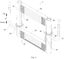
Fig. 1 is a schematic view of a heat exchanger according to embodiments of the present disclosure. -
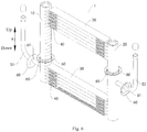
Fig. 2 is a schematic view of a heat exchanger according to a first optional embodiment of the present disclosure. -
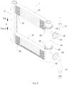
Fig. 3 is a schematic view of a heat exchanger according to a second optional embodiment of the present disclosure. -
Fig. 4 is a schematic view of a heat exchanger according to a third optional embodiment of the present disclosure. -
Fig. 5 is a schematic view of a heat exchanger according to a fourth optional embodiment of the present disclosure. -
Fig. 6 is a schematic view of a heat exchanger according to a fifth optional embodiment of the present disclosure. -
Fig. 7 is a schematic view of a heat exchanger according to a sixth optional embodiment of the present disclosure. -
Fig. 8 is a schematic view of a heat exchanger according to a seventh optional embodiment of the present disclosure. -
Fig. 9 is a schematic view of a heat exchanger according to an eighth optional embodiment of the present disclosure. - Reference numerals:
heat exchanger 1,first header 10,second header 20,flat tube 30,fin 40,inlet pipe 51,outlet pipe 52,water guiding member 60,notch 61,water leading bar 62,bracket 63,elastic member 64,water discharge port 65,water leading plate 66. - Embodiments of the present disclosure will be described in detail and examples of the embodiments will be illustrated in the accompanying drawings. The same or similar elements and the elements having same or similar functions are denoted by like reference numerals throughout the descriptions. The embodiments described herein with reference to the drawings are explanatory, which aim to illustrate the present disclosure, but shall not be construed to limit the present disclosure.
- A
heat exchanger 1 according to embodiments of the present disclosure will be described with reference to the drawings. Those skilled in the art should understand that an up-and-down direction mentioned below refers to an up-and-down direction when theheat exchanger 1 is normally used. - As illustrated in
Figs. 1 to 9 , theheat exchanger 1 includes afirst header 10, asecond header 20,flat tubes 30, afin 40, an input-output pipe and afin 40. - The
first header 10 and thesecond header 20 are disposed vertically and spaced apart from each other. Theflat tube 30 is disposed horizontally, and has two ends connected with thefirst header 10 and thesecond header 20 respectively. Thefin 40 is configured as a corrugated fin and disposed between adjacentflat tubes 30. The input-output pipe is welded to at least one header of thefirst header 10 and thesecond header 20. Thewater guiding member 60 is disposed to the input-output pipe and/or the at least one header. In other words, thewater guiding member 60 may be disposed to the input-output pipe, or may be disposed to the header welded with the input-output pipe, or may be disposed to both of the input-output pipe and the header welded with the input-output pipe. - The input-output pipe includes an
inlet pipe 51 and anoutlet pipe 52. Theinlet pipe 51 and theoutlet pipe 52 may be simultaneously disposed to one of thefirst header 10 and the second header 20 (as illustrated inFigs. 3 ,5 ,8 and9 ). Or, theinlet pipe 51 may be disposed to thefirst header 10 and theoutlet pipe 52 may be disposed to the second header 20 (as illustrated inFigs. 1 ,2 ,4 ,6 and7 ). - For the
heat exchanger 1 according to embodiments of the present disclosure, by providing thewater guiding member 60 to the input-output pipe and/or the header welded with the input-output pipe, water accumulated on a specific part of a surface of theheat exchanger 1 can be drained off to the outside of theheat exchanger 1 by means of thewater guiding member 60, so as to prevent water from accumulating or flowing across the surface of theheat exchanger 1. For example, it is possible to prevent water from accumulating at a welded joint of the input-output pipe and the header, and especially, when theheat exchanger 1 is used as an evaporator or is applied to a heat pump, it is possible to prevent rainwater from flowing across a weak area of theheat exchanger 1 that is exposed to the air, so as to prevent metal ions or other active media entrained in the rain from corroding the surface of theheat exchanger 1, thereby greatly reducing a risk of corrosion of theheat exchanger 1 and hence prolonging a service life of theheat exchanger 1. Thus, theheat exchanger 1 according to embodiments of the present disclosure is able to avoid corrosion due to water accumulation on the surface thereof and has an advantage of long service life. - The
heat exchanger 1 according to specific embodiments of the present disclosure will be described with reference to the drawings. - In some specific embodiments of the present disclosure, as shown in
Figs. 1-9 , theheat exchanger 1 according to the embodiments of the present disclosure includes thefirst header 10, thesecond header 20, theflat tubes 30, thefin 40, the input-output pipe and thefin 40. - Further, the
water guiding member 60 is disposed adjacent to a welding position where the input-output pipe and the at least one header are welded. The water on the surface of theheat exchanger 1 will be discharged out of theheat exchanger 1 by means of thewater guiding member 60 before flowing to the welded joint of the input-output pipe and the header, so as to more effectively prevent water from accumulating at the welded joint of the input-output pipe and the header. - In some specific examples of the present disclosure, as shown in
Figs. 1-3 , thewater guiding member 60 is disposed to the input-output pipe, and thewater guiding member 60 can prevent water on the input-output pipe from flowing along an outer wall of the input-output pipe to the welded joint of the input-output pipe and the header. - Optionally, as illustrated in
Fig. 1 , thewater guiding member 60 is configured as a water guiding disc fitted over the input-output pipe. The water guiding disc is configured as a circular or oval disc with an opening facing away from the header welded to the input-output pipe, and a peripheral edge of the water guiding disc is provided with a circle of protrusion extending outwardly. The water guiding disc collects water flowing along the input-output pipe and guides the collected water to be discharged under action of gravity, so as to prevent water on the input-output pipe from flowing to the welded joint of the input-output pipe and the header. In addition, the provision of the water guiding disc will not affect a heat exchange channel or increase an air resistance, thereby avoiding influences on a heat exchange performance. - Advantageously, as illustrated in
Fig. 1 , the water guiding disc (i.e. the water guiding member 60) can be made of rubber or other soft and corrosion-resistant materials, and the water guiding disc has anotch 61 extending along a radial direction of the water guiding disc and cutting the water guiding disc. The water guiding disc may allow the input-output pipe to directly pass through itself, so as to be fitted over the input-output pipe, or the water guiding disc may also be mounted to the input-output pipe in a clipping manner by means of thenotch 61, such that the mounting of the water guiding disc can be facilitated, and can be realized in flexible manners so as to adapt to input-output pipes of different pipe diameters. - Further, as illustrated in
Fig. 1 , a lower edge of the water guiding disc (i.e. the water guiding member 60) is provided with awater leading bar 62 extending downwards from the water guiding disc, and thewater leading bar 62 can lead the water on the water guiding disc to flow downwards and out of theheat exchanger 1, so as to further prevent the water on the input-output pipe from flowing to the welded joint of the input-output pipe and the header. - In some specific embodiments of the present disclosure, as illustrated in
Fig. 2 , thewater guiding member 60 is configured as a water retaining block, an upper surface of the water retaining block is provided with a groove configured to be fitted with the input-output pipe, and in a cross section of the input-output pipe, at least a lower half of the input-output pipe is fitted in the groove, i.e. the water retaining block and a wall of at least the lower half of the input-output pipe fit closely together. Hence, the water on the input-output pipe will be retained by the water retaining block when flowing to the water retaining block, and cannot continue flowing to the welded joint of the input-output pipe and the header. - Specifically, as illustrated in
Fig. 2 , the header welded with the input-output pipe is provided with abracket 63, thebracket 63 may be fastened to the header through a hoop, a tie or a spring, anelastic member 64 is provided on thebracket 63, and the water guiding disc (i.e. the water guiding member 60) is configured as a flexible block and disposed on theelastic member 64. Theelastic member 64 can ensure that the water retaining block and the input-output pipe fit closely together, and thebracket 63 is configured to support theelastic member 64 and the water retaining block. Those skilled in the art could understand that thebracket 63 can also serve as a mounting bracket for theheat exchanger 1 so as to facilitate the assembling of theheat exchanger 1 and units. - In some specific examples of the present disclosure, as illustrated in
Figs. 1 and2 , theinlet pipe 51 is welded to thefirst header 10 and theoutlet pipe 52 is welded to thesecond header 20. A heat transfer medium enters thefirst header 10 through theinlet pipe 51, flows into thesecond header 20 through theflat tubes 30, and finally flows out of theoutlet pipe 52. At least one of theinlet pipe 51 and theoutlet pipe 52 is provided with thewater guiding member 60 adjacent to the corresponding header. - As illustrated in
Fig. 3 , theinlet pipe 51 and theoutlet pipe 52 may be simultaneously welded to one header of thefirst header 10 and thesecond header 20, and thefirst header 10 and thesecond header 20 each are provided with a baffle therein. After entering from theinlet pipe 51, a cooling medium flows in a serpentine manner between thefirst header 10 and thesecond header 20 through theflat tubes 30 under the guidance of the baffles, and finally flows out of theoutlet pipe 52. At least one of theinlet pipe 51 and theoutlet pipe 52 is provided with thewater guiding member 60 adjacent to the corresponding header. - In some specific embodiments of the present disclosure, as illustrated in
Figs. 4 and5 , thewater guiding member 60 is disposed to the header welded with the input-output pipe, and thewater guiding member 60 is located above the welding position where the input-output pipe and the header are welded, such that thewater guiding member 60 can prevent water on the header from flowing along an outer wall of the header to the welded joint of the input-output pipe and the header. - Optionally, as illustrated in
Figs. 4 and5 , thewater guiding member 60 is configured as a water guiding disc fitted over the header. The water guiding disc is a circular or oval disc with an opening facing upwards, and a peripheral edge of the water guiding disc is provided with a circle of protrusion extending outwardly. The water guiding disc collects water flowing along the header to prevent the water on the header from flowing to the welded joint of the input-output pipe and the header. In addition, the provision of the water guiding disc will not affect a heat exchange channel or increase an air resistance, thereby avoiding an influence on the heat exchange performance. - Advantageously, as illustrated in
Figs. 4 and5 , the water guiding disc (i.e. the water guiding member 60) may be made of rubber or other soft and corrosion-resistant materials, and the water guiding disc has anotch 61 extending along a radial direction of the water guiding disc and cutting the water guiding disc. The water guiding disc may allow the header to directly pass through itself, so as to be fitted over the header, or the water guiding disc may be mounted to the header in a clipping manner by means of thenotch 61, such that the mounting of the water guiding disc can be facilitated, and can be realized in flexible manners so as to adapt to input-output pipes of different pipe diameters. - Further, as illustrated in
Fig. 4 , an edge of the water guiding disc (i.e. the water guiding member 60) is provided with awater discharge port 65, and the water guiding disc is provided with awater leading bar 62 extending downwards from thewater discharge port 65. Thus, after the water guiding disc is full of the collected water, the collected water overflows from thewater discharge port 65 and flows downwards along thewater leading bar 62 to be discharged out of theheat exchanger 1. - In some specific examples of the present disclosure, as illustrated in
Fig. 4 , theinlet pipe 51 is connected to thefirst header 10 and theoutlet pipe 52 is connected to thesecond header 20. The heat transfer medium enters thefirst header 10 through theinlet pipe 51, flows into thesecond header 20 through theflat tubes 30, and finally flows out of theoutlet pipe 52. At least one of thefirst header 10 and thesecond header 20 is provided with thewater guiding member 60. - As illustrated in
Fig. 5 , theinlet pipe 51 and theoutlet pipe 52 may also be simultaneously welded to one header of thefirst header 10 and thesecond header 20, and thefirst header 10 and thesecond header 20 each are provided with a baffle therein. After entering from theinlet pipe 51, the cooling medium flows in a serpentine manner between thefirst header 10 and thesecond header 20 through theflat tubes 30 under the guidance of the baffles, and finally flows out of theoutlet pipe 52. On the one header simultaneously welded with theinlet pipe 51 and theoutlet pipe 52, thewater guiding member 60 is provided above at least one welding position of a welding position where theinlet pipe 51 and the one header are welded and another welding position where theoutlet pipe 52 and the one header are welded. In other words, at least onewater guiding member 60 is provided to the one header simultaneously welded with theinlet pipe 51 and theoutlet pipe 52, and located above the corresponding welding position. - In some specific embodiments of the present disclosure, as illustrated in
Figs. 6 and7 , theinlet pipe 51 is welded to thefirst header 10, while theoutlet pipe 52 is welded to thesecond header 20. The heat transfer medium enters thefirst header 10 through theinlet pipe 51, then flows into thesecond header 20 through theflat tubes 30, and finally flows out of theoutlet pipe 52. Theinlet pipe 51, theoutlet pipe 52, thefirst header 10 and thesecond header 20 each are provided with thewater guiding member 60. Thus, it is possible to prevent water on theinlet pipe 51, theoutlet pipe 52, thefirst header 10 and thesecond header 20 from flowing to a welded joint of theinlet pipe 51 and thefirst header 10 and a welded joint of theoutlet pipe 52 and thesecond header 20, so as to reduce a risk of corroding the welded joint of theinlet pipe 51 and thefirst header 10 and the welded joint of theoutlet pipe 52 and thesecond header 20, thereby improving the service life of theheat exchanger 1. - Optionally, as illustrated in
Figs. 6 and7 , thewater guiding member 60 is configured as a circular or oval disc-shaped water guiding disc, a peripheral edge of the water guiding disc is provided with a circle of protrusion extending outwardly, and the water guiding disc may be made of rubber or other soft and corrosion-resistant materials. The water guiding disc has a central mounting hole for fitting the water guiding disc over the corresponding pipe, and the water guiding disc is further provided with anotch 61 in communication with the central mounting hole and extending along a radial direction of the water guiding disc, in which thenotch 61 can further facilitate the mounting of the water guiding disc. - Further, as illustrated in
Fig. 7 , thewater guiding member 60 of thefirst header 10 is connected with thewater guiding member 60 of theinlet pipe 51 by means of awater leading plate 66, and thewater guiding member 60 of thesecond header 20 is connected with thewater guiding member 60 of theoutlet pipe 52 by means of anotherwater leading plate 66. Eachwater leading plate 66 is an arc plate facing upwards and protruding away from the welding position. Thus, twowater leading plates 66 and fourwater guiding members 60 can be used to separate the welded joint of theinlet pipe 51 and thefirst header 10 and the welded joint of theoutlet pipe 52 and thesecond header 20 from the external environment, so as to further prevent water from accumulating or flowing across the welded joint of theinlet pipe 51 and thefirst header 10 and the welded joint of theoutlet pipe 52 and thesecond header 20. - In some specific embodiments of the present disclosure, as illustrated in
Figs. 8 and9 , theinlet pipe 51 and theoutlet pipe 52 are both welded to thefirst header 10, and thefirst header 10 and thesecond header 20 both are provided with a baffle therein. After entering thefirst header 10 from theinlet pipe 51, the cooling medium flows in a serpentine manner between thefirst header 10 and thesecond header 20 through theflat tubes 30 under the guidance of the baffles, finally flows back to thefirst header 10 and flows out of theoutlet pipe 52. Theinlet pipe 51, theoutlet pipe 52 and thefirst header 10 are provided with thewater guiding member 60 respectively. Those skilled in the art should understand that thefirst header 10 may be provided with onewater guiding member 60, and thiswater guiding member 60 is located above the higher one of theinlet pipe 51 and theoutlet pipe 52. Thefirst header 10 may also be provided with twowater guiding members 60, one of the twowater guiding members 60 is located above theinlet pipe 51 and the other one of the twowater guiding members 60 is located above theoutlet pipe 52. Thus, it is possible to prevent water on theinlet pipe 51, theoutlet pipe 52 and thefirst header 10 from flowing to a welded joint of theinlet pipe 51 and thefirst header 10 and a welded joint of theoutlet pipe 52 and thefirst header 10, so as to reduce a risk of corroding the welded joint of theinlet pipe 51 and thefirst header 10 and the welded joint of theoutlet pipe 52 and thefirst header 10, thereby prolonging the service life of theheat exchanger 1. - Optionally, as illustrated in
Figs. 8 and9 , thewater guiding member 60 is configured as a circular or oval disc-shaped water guiding disc, a peripheral edge of the water guiding disc is provided with a circle of protrusion extending outwardly, and the water guiding disc may be made of rubber or other soft and corrosion-resistant materials. The water guiding disc has a central mounting hole for fitting the water guiding disc over the corresponding pipe, and the water guiding disc is further provided with anotch 61 in communication with the central mounting hole and extending along a radial direction of the water guiding disc, in which thenotch 61 can further facilitate the mounting of the water guiding disc. - Further, as illustrated in
Fig. 9 , thefirst header 10 is provided with twowater guiding members 60, one of the twowater guiding members 60 is located above theinlet pipe 51 and the other one of the twowater guiding members 60 is located above theoutlet pipe 52. The twowater guiding members 60 of thefirst header 10 are connected with the guidingmember 60 of theinlet pipe 51 by means of awater leading plate 66 and with the guidingmember 60 of theoutlet pipe 52 by means of anotherwater leading plate 66. Eachwater leading plate 66 is configured as an arc plate facing upwards and protruding away from the welding position. Thus, twowater leading plates 66 and fourwater guiding members 60 can be used to separate the welded joint of theinlet pipe 51 and thefirst header 10 and the welded joint of theoutlet pipe 52 and thefirst header 10 from the external environment, so as to further prevent water from accumulating or flowing across the welded joint of theinlet pipe 51 and thefirst header 10 and the welded joint of theoutlet pipe 52 and thefirst header 10. - Other configurations and operations of the
heat exchanger 1 according to embodiments of the present disclosure are known to those skilled in the art, which will not be elaborated herein. - In the specification, it is to be understood that terms such as "central," "longitudinal," "lateral," "length," "width," "thickness," "upper," "lower," "front," "rear," "left," "right," "vertical," "horizontal," "top," "bottom," "inner," "outer," "clockwise," and "counterclockwise" should be construed to refer to the orientation as then described or as shown in the drawings under discussion. These relative terms are only used to simplify description of the present disclosure, and do not indicate or imply that the device or element referred to must have a particular orientation, or constructed or operated in a particular orientation. Thus, these terms cannot be constructed to limit the present disclosure.
- In addition, terms such as "first" and "second" are used herein for purposes of description and are not intended to indicate or imply relative importance or significance or to imply the number of indicated technical features. Thus, the feature defined with "first" and "second" may comprise one or more of this feature. In the description of the present disclosure, "a plurality of' means two or more than two, unless specified otherwise.
- In the present disclosure, unless specified or limited otherwise, the terms "mounted," "connected," "coupled," "fixed" and the like are used broadly, and may be, for example, fixed connections, detachable connections, or integral connections; may also be mechanical or electrical connections; may also be direct connections or indirect connections via intervening structures; may also be inner communications of two elements, which can be understood by those skilled in the art according to specific situations.
- In the present disclosure, unless specified or limited otherwise, a structure in which a first feature is "on" or "below" a second feature may include an embodiment in which the first feature is in direct contact with the second feature, and may also include an embodiment in which the first feature and the second feature are not in direct contact with each other, but are contacted via an additional feature formed therebetween. Furthermore, a first feature "on," "above," or "on top of' a second feature may include an embodiment in which the first feature is right or obliquely "on," "above," or "on top of' the second feature, or just means that the first feature is at a height higher than that of the second feature; while a first feature "below," "under," or "on bottom of' a second feature may include an embodiment in which the first feature is right or obliquely "below," "under," or "on bottom of' the second feature, or just means that the first feature is at a height lower than that of the second feature.
- Reference throughout this specification to "an embodiment," "some embodiments," "an example," "a specific example," or "some examples," means that a particular feature, structure, material, or characteristic described in connection with the embodiment or example is included in at least one embodiment or example of the present disclosure. Thus, the appearances of the above phrases throughout this specification are not necessarily referring to the same embodiment or example of the present disclosure. Furthermore, the particular features, structures, materials, or characteristics may be combined in any suitable manner in one or more embodiments or examples.
- Although embodiments of the present disclosure have been shown and described, it would be appreciated by those skilled in the art that changes, modifications, alternatives and variations can be made in the embodiments without departing from the scope of the present disclosure.
Claims (20)
- A heat exchanger, comprising:a first header and a second header;flat tubes, each having two ends connected to the first header and the second header respectively;a fin arranged between adjacent flat tubes;an input-output pipe welded to at least one header of the first header and the second header; anda water guiding member disposed to the input-output pipe and/or the at least one header.
- The heat exchanger according to claim 1, wherein the water guiding member is arranged adjacent to a welding position where the input-output pipe and the at least one header are welded.
- The heat exchanger according to claim 1, wherein the water guiding member is disposed to the input-output pipe.
- The heat exchanger according to claim 3, wherein the water guiding member is configured as a water guiding disc fitted over the input-output pipe.
- The heat exchanger according to claim 4, wherein the water guiding disc has a notch, which allows the water guiding disc to be fitted over the input-output pipe and extends along a radial direction of the water guiding disc.
- The heat exchanger according to claim 4, wherein a lower edge of the water guiding disc is provided with a water leading bar extending downwards from the water guiding disc.
- The heat exchanger according to claim 3, wherein the water guiding member is configured as a water retaining block, an upper surface of the water retaining block is provided with a groove configured to be fitted with the input-output pipe, and in a cross section of the input-output pipe, at least a lower half of the input-output pipe is fitted in the groove.
- The heat exchanger according to claim 7, further comprising:a bracket connected with the at least one header; andan elastic member arranged on the bracket, the water retaining block being configured as a flexible block and arranged on the elastic member.
- The heat exchanger according to any one of claims 3 to 8, wherein the input-output pipe comprises an inlet pipe and an outlet pipe, the inlet pipe and the outlet pipe are simultaneously welded to one of the first header and the second header or are respectively welded to the first header and the second header, and the water guiding member is disposed to at least one of the inlet pipe and the outlet pipe.
- The heat exchanger according to claim 1, wherein the water guiding member is disposed to the at least one header and located above a welding position where the input-output pipe and the at least one header are welded.
- The heat exchanger according to claim 10, wherein the water guiding member is configured as a water guiding disc fitted over the at least one header.
- The heat exchanger according to claim 11, wherein the water guiding disc has a notch, which allows the water guiding disc to be fitted over the at least one header and extends along a radial direction of the water guiding disc.
- The heat exchanger according to claim 11, wherein an edge of the water guiding disc is provided with a water discharge port.
- The heat exchanger according to claim 13, wherein the water guiding disc is provided with a water leading bar extending downwards from the water discharge port.
- The heat exchanger according to any one of claims 10 to 14, wherein the input-output pipe comprises an inlet pipe and an outlet pipe,
the inlet pipe and the outlet pipe are simultaneously welded to one header of the first header and the second header, and the water guiding member is provided to the one header above at least one welding position of a welding position where the inlet pipe and the one header are welded and another welding position where the outlet pipe and the one header are welded; or
the inlet pipe and the outlet pipe are connected to the first header and the second header respectively, and the water guiding member is provided to at least one of the first header and the second header. - The heat exchanger according to claim 1, wherein the input-output pipe comprises an inlet pipe welded with the first header and an outlet pipe welded with the second header, each of the inlet pipe and the outlet pipe is provided with the water guiding member, and each of the first header and the second header is provided with the water guiding member.
- The heat exchanger according to claim 16, wherein the water guiding member of the first header is connected with the water guiding member of the inlet pipe by means of a water leading plate, and the water guiding member of the second header is connected with the water guiding member of the outlet pipe by means of another water leading plate.
- The heat exchanger according to claim 1, wherein the input-output pipe comprises an inlet pipe welded with the first header and an outlet pipe welded with the first header, each of the inlet pipe and the outlet pipe is provided with the water guiding member, and the first header is provided with the water guiding member.
- The heat exchanger according to claim 18, wherein the water guiding member of the first header is connected with the water guiding member of the inlet pipe and the water guiding member of the outlet pipe by means of water leading plates respectively.
- The heat exchanger according to any one of claims 16 to 19, wherein the water guiding member is configured as a water guiding disc, and the water guiding disc has a central mounting hole, and a notch in communication with the central mounting hole and extending along a radial direction of the water guiding disc.
Applications Claiming Priority (2)
| Application Number | Priority Date | Filing Date | Title |
|---|---|---|---|
| CN201520502739.2U CN204830986U (en) | 2015-07-10 | 2015-07-10 | Heat exchanger |
| PCT/CN2016/088627 WO2017008662A1 (en) | 2015-07-10 | 2016-07-05 | Heat exchanger |
Publications (3)
| Publication Number | Publication Date |
|---|---|
| EP3321598A1 true EP3321598A1 (en) | 2018-05-16 |
| EP3321598A4 EP3321598A4 (en) | 2019-03-13 |
| EP3321598B1 EP3321598B1 (en) | 2021-01-06 |
Family
ID=54688579
Family Applications (1)
| Application Number | Title | Priority Date | Filing Date |
|---|---|---|---|
| EP16823809.5A Active EP3321598B1 (en) | 2015-07-10 | 2016-07-05 | Heat exchanger |
Country Status (4)
| Country | Link |
|---|---|
| US (1) | US10704844B2 (en) |
| EP (1) | EP3321598B1 (en) |
| CN (1) | CN204830986U (en) |
| WO (1) | WO2017008662A1 (en) |
Families Citing this family (4)
| Publication number | Priority date | Publication date | Assignee | Title |
|---|---|---|---|---|
| CN105846012B (en) * | 2016-06-16 | 2018-06-05 | 哲弗智能系统(上海)有限公司 | A kind of power battery pack heat exchanger plates |
| CN107940812A (en) * | 2017-09-30 | 2018-04-20 | 博格思众(常州)热交换器有限公司 | A kind of manufacture method of fin, evaporator and fin |
| JP6847328B1 (en) * | 2020-05-15 | 2021-03-24 | 三菱電機株式会社 | Indoor unit of air conditioner and air conditioner |
| CN212431901U (en) * | 2020-06-23 | 2021-01-29 | 丹佛斯有限公司 | Collecting pipe assembly and heat exchanger |
Family Cites Families (12)
| Publication number | Priority date | Publication date | Assignee | Title |
|---|---|---|---|---|
| JPH04129686U (en) * | 1991-05-10 | 1992-11-27 | サンデン株式会社 | Heat exchanger |
| DE10127796C1 (en) | 2001-06-07 | 2002-10-10 | Oskar Fleck | Ventilator or flue has conical connector below roof which connects pipe above it with that below it, base of connector forming annular trough in which condensate collects and is run off through outlet |
| JP4759312B2 (en) * | 2004-05-10 | 2011-08-31 | 昭和電工株式会社 | Manufacturing method of heat exchanger |
| JP5097542B2 (en) | 2004-05-24 | 2012-12-12 | ザ リージェンツ オブ ザ ユニバーシティ オブ カリフォルニア | High-speed clock distribution transmission line network |
| KR100831850B1 (en) | 2006-12-14 | 2008-05-22 | 모딘코리아 유한회사 | Heat exchanger |
| KR100927948B1 (en) * | 2007-04-23 | 2009-11-23 | 주식회사 유엠하이텍 | Header Pipe for Heat Exchanger with Filler Grooves |
| US20110042047A1 (en) | 2008-05-14 | 2011-02-24 | Carrier Corporation | Heat exchanger drip tube |
| JP2010025479A (en) | 2008-07-22 | 2010-02-04 | Daikin Ind Ltd | Heat exchanger |
| CN102252558B (en) | 2011-05-06 | 2013-04-10 | 三花控股集团有限公司 | Heat exchange device |
| CN102889819B (en) | 2012-10-15 | 2014-03-12 | 三花控股集团有限公司 | Header pipe and heat exchanger |
| CN202902995U (en) | 2012-10-15 | 2013-04-24 | 三花控股集团有限公司 | Condensate water diversion structure for heat exchanger and heat exchanger |
| CN203100483U (en) | 2013-01-07 | 2013-07-31 | 广东美的电器股份有限公司 | Heat exchanger |
-
2015
- 2015-07-10 CN CN201520502739.2U patent/CN204830986U/en active Active
-
2016
- 2016-07-05 EP EP16823809.5A patent/EP3321598B1/en active Active
- 2016-07-05 WO PCT/CN2016/088627 patent/WO2017008662A1/en active Application Filing
- 2016-07-05 US US15/743,071 patent/US10704844B2/en active Active
Also Published As
| Publication number | Publication date |
|---|---|
| WO2017008662A1 (en) | 2017-01-19 |
| CN204830986U (en) | 2015-12-02 |
| EP3321598A4 (en) | 2019-03-13 |
| US10704844B2 (en) | 2020-07-07 |
| EP3321598B1 (en) | 2021-01-06 |
| US20190078848A1 (en) | 2019-03-14 |
Similar Documents
| Publication | Publication Date | Title |
|---|---|---|
| US10704844B2 (en) | Heat exchanger | |
| JP5464207B2 (en) | Refrigeration unit outdoor unit | |
| US10113756B2 (en) | Air-conditioning-apparatus outdoor unit and method of manufacturing air-conditioning-apparatus outdoor unit | |
| CN110036244B (en) | Outdoor unit of air conditioner and air conditioner provided with same | |
| WO2014059900A1 (en) | Condensate water diversion structure for heat exchanger, and heat exchanger | |
| CN107091523B (en) | Condensed water collecting device, heat exchange assembly and air conditioner | |
| WO2013118583A1 (en) | Outdoor unit for refrigeration device | |
| CN210321335U (en) | Heat exchanger | |
| CN107860248B (en) | Microchannel heat exchanger and air conditioner | |
| CN110645694A (en) | Water collector and air conditioner | |
| CN201819374U (en) | Heat exchanger provided with installation components | |
| JP5772590B2 (en) | Refrigeration unit outdoor unit | |
| JP2010065892A (en) | Heat exchanger | |
| CN111721036B (en) | Heat exchanger | |
| CN108344210B (en) | Parallel flow heat exchange system for improving heat exchange efficiency | |
| JP6932262B2 (en) | Heat exchanger, heat exchanger unit, and refrigeration cycle equipment | |
| CN220326117U (en) | Inclined air conditioner surface cooler | |
| CN207865671U (en) | A kind of indoor machine evaporation flow-guiding structure and air conditioner | |
| CN211552582U (en) | Air conditioner and finned heat exchanger thereof | |
| CN215983191U (en) | Heat exchanger and air conditioner | |
| WO2014199514A1 (en) | Outdoor unit for air conditioner and production method for outdoor unit for air conditioner | |
| CN217877247U (en) | A fin, heat exchanger and air conditioner for heat exchanger | |
| CN217383868U (en) | Heat exchanger | |
| CN210772708U (en) | Water collector and air conditioner | |
| CN214333030U (en) | Water pan and air indirect heating equipment of two-way drainage |
Legal Events
| Date | Code | Title | Description |
|---|---|---|---|
| STAA | Information on the status of an ep patent application or granted ep patent |
Free format text: STATUS: THE INTERNATIONAL PUBLICATION HAS BEEN MADE |
|
| PUAI | Public reference made under article 153(3) epc to a published international application that has entered the european phase |
Free format text: ORIGINAL CODE: 0009012 |
|
| STAA | Information on the status of an ep patent application or granted ep patent |
Free format text: STATUS: REQUEST FOR EXAMINATION WAS MADE |
|
| 17P | Request for examination filed |
Effective date: 20180208 |
|
| AK | Designated contracting states |
Kind code of ref document: A1 Designated state(s): AL AT BE BG CH CY CZ DE DK EE ES FI FR GB GR HR HU IE IS IT LI LT LU LV MC MK MT NL NO PL PT RO RS SE SI SK SM TR |
|
| AX | Request for extension of the european patent |
Extension state: BA ME |
|
| DAV | Request for validation of the european patent (deleted) | ||
| DAX | Request for extension of the european patent (deleted) | ||
| A4 | Supplementary search report drawn up and despatched |
Effective date: 20190207 |
|
| RIC1 | Information provided on ipc code assigned before grant |
Ipc: F28F 1/32 20060101ALI20190201BHEP Ipc: F28F 19/00 20060101ALI20190201BHEP Ipc: F28F 17/00 20060101ALI20190201BHEP Ipc: F28F 1/12 20060101ALI20190201BHEP Ipc: F28D 1/053 20060101ALI20190201BHEP Ipc: F24F 1/36 20110101AFI20190201BHEP Ipc: F24F 13/22 20060101ALI20190201BHEP |
|
| RIC1 | Information provided on ipc code assigned before grant |
Ipc: F28D 1/053 20060101ALI20200630BHEP Ipc: F28F 1/12 20060101ALI20200630BHEP Ipc: F28F 17/00 20060101ALI20200630BHEP Ipc: F24F 1/36 20110101AFI20200630BHEP Ipc: F28F 1/32 20060101ALI20200630BHEP Ipc: F24F 13/22 20060101ALI20200630BHEP Ipc: F28F 19/00 20060101ALI20200630BHEP |
|
| GRAP | Despatch of communication of intention to grant a patent |
Free format text: ORIGINAL CODE: EPIDOSNIGR1 |
|
| STAA | Information on the status of an ep patent application or granted ep patent |
Free format text: STATUS: GRANT OF PATENT IS INTENDED |
|
| INTG | Intention to grant announced |
Effective date: 20201019 |
|
| GRAS | Grant fee paid |
Free format text: ORIGINAL CODE: EPIDOSNIGR3 |
|
| GRAA | (expected) grant |
Free format text: ORIGINAL CODE: 0009210 |
|
| STAA | Information on the status of an ep patent application or granted ep patent |
Free format text: STATUS: THE PATENT HAS BEEN GRANTED |
|
| AK | Designated contracting states |
Kind code of ref document: B1 Designated state(s): AL AT BE BG CH CY CZ DE DK EE ES FI FR GB GR HR HU IE IS IT LI LT LU LV MC MK MT NL NO PL PT RO RS SE SI SK SM TR |
|
| REG | Reference to a national code |
Ref country code: GB Ref legal event code: FG4D |
|
| REG | Reference to a national code |
Ref country code: AT Ref legal event code: REF Ref document number: 1352777 Country of ref document: AT Kind code of ref document: T Effective date: 20210115 Ref country code: CH Ref legal event code: EP |
|
| REG | Reference to a national code |
Ref country code: DE Ref legal event code: R096 Ref document number: 602016051144 Country of ref document: DE |
|
| REG | Reference to a national code |
Ref country code: IE Ref legal event code: FG4D |
|
| REG | Reference to a national code |
Ref country code: NL Ref legal event code: MP Effective date: 20210106 |
|
| REG | Reference to a national code |
Ref country code: AT Ref legal event code: MK05 Ref document number: 1352777 Country of ref document: AT Kind code of ref document: T Effective date: 20210106 |
|
| REG | Reference to a national code |
Ref country code: LT Ref legal event code: MG9D |
|
| PG25 | Lapsed in a contracting state [announced via postgrant information from national office to epo] |
Ref country code: PT Free format text: LAPSE BECAUSE OF FAILURE TO SUBMIT A TRANSLATION OF THE DESCRIPTION OR TO PAY THE FEE WITHIN THE PRESCRIBED TIME-LIMIT Effective date: 20210506 Ref country code: NO Free format text: LAPSE BECAUSE OF FAILURE TO SUBMIT A TRANSLATION OF THE DESCRIPTION OR TO PAY THE FEE WITHIN THE PRESCRIBED TIME-LIMIT Effective date: 20210406 Ref country code: GR Free format text: LAPSE BECAUSE OF FAILURE TO SUBMIT A TRANSLATION OF THE DESCRIPTION OR TO PAY THE FEE WITHIN THE PRESCRIBED TIME-LIMIT Effective date: 20210407 Ref country code: FI Free format text: LAPSE BECAUSE OF FAILURE TO SUBMIT A TRANSLATION OF THE DESCRIPTION OR TO PAY THE FEE WITHIN THE PRESCRIBED TIME-LIMIT Effective date: 20210106 Ref country code: HR Free format text: LAPSE BECAUSE OF FAILURE TO SUBMIT A TRANSLATION OF THE DESCRIPTION OR TO PAY THE FEE WITHIN THE PRESCRIBED TIME-LIMIT Effective date: 20210106 Ref country code: BG Free format text: LAPSE BECAUSE OF FAILURE TO SUBMIT A TRANSLATION OF THE DESCRIPTION OR TO PAY THE FEE WITHIN THE PRESCRIBED TIME-LIMIT Effective date: 20210406 Ref country code: LT Free format text: LAPSE BECAUSE OF FAILURE TO SUBMIT A TRANSLATION OF THE DESCRIPTION OR TO PAY THE FEE WITHIN THE PRESCRIBED TIME-LIMIT Effective date: 20210106 |
|
| PG25 | Lapsed in a contracting state [announced via postgrant information from national office to epo] |
Ref country code: AT Free format text: LAPSE BECAUSE OF FAILURE TO SUBMIT A TRANSLATION OF THE DESCRIPTION OR TO PAY THE FEE WITHIN THE PRESCRIBED TIME-LIMIT Effective date: 20210106 Ref country code: PL Free format text: LAPSE BECAUSE OF FAILURE TO SUBMIT A TRANSLATION OF THE DESCRIPTION OR TO PAY THE FEE WITHIN THE PRESCRIBED TIME-LIMIT Effective date: 20210106 Ref country code: RS Free format text: LAPSE BECAUSE OF FAILURE TO SUBMIT A TRANSLATION OF THE DESCRIPTION OR TO PAY THE FEE WITHIN THE PRESCRIBED TIME-LIMIT Effective date: 20210106 Ref country code: LV Free format text: LAPSE BECAUSE OF FAILURE TO SUBMIT A TRANSLATION OF THE DESCRIPTION OR TO PAY THE FEE WITHIN THE PRESCRIBED TIME-LIMIT Effective date: 20210106 Ref country code: SE Free format text: LAPSE BECAUSE OF FAILURE TO SUBMIT A TRANSLATION OF THE DESCRIPTION OR TO PAY THE FEE WITHIN THE PRESCRIBED TIME-LIMIT Effective date: 20210106 |
|
| PG25 | Lapsed in a contracting state [announced via postgrant information from national office to epo] |
Ref country code: IS Free format text: LAPSE BECAUSE OF FAILURE TO SUBMIT A TRANSLATION OF THE DESCRIPTION OR TO PAY THE FEE WITHIN THE PRESCRIBED TIME-LIMIT Effective date: 20210506 |
|
| REG | Reference to a national code |
Ref country code: DE Ref legal event code: R097 Ref document number: 602016051144 Country of ref document: DE |
|
| PG25 | Lapsed in a contracting state [announced via postgrant information from national office to epo] |
Ref country code: EE Free format text: LAPSE BECAUSE OF FAILURE TO SUBMIT A TRANSLATION OF THE DESCRIPTION OR TO PAY THE FEE WITHIN THE PRESCRIBED TIME-LIMIT Effective date: 20210106 Ref country code: CZ Free format text: LAPSE BECAUSE OF FAILURE TO SUBMIT A TRANSLATION OF THE DESCRIPTION OR TO PAY THE FEE WITHIN THE PRESCRIBED TIME-LIMIT Effective date: 20210106 Ref country code: SM Free format text: LAPSE BECAUSE OF FAILURE TO SUBMIT A TRANSLATION OF THE DESCRIPTION OR TO PAY THE FEE WITHIN THE PRESCRIBED TIME-LIMIT Effective date: 20210106 |
|
| PLBE | No opposition filed within time limit |
Free format text: ORIGINAL CODE: 0009261 |
|
| STAA | Information on the status of an ep patent application or granted ep patent |
Free format text: STATUS: NO OPPOSITION FILED WITHIN TIME LIMIT |
|
| PG25 | Lapsed in a contracting state [announced via postgrant information from national office to epo] |
Ref country code: RO Free format text: LAPSE BECAUSE OF FAILURE TO SUBMIT A TRANSLATION OF THE DESCRIPTION OR TO PAY THE FEE WITHIN THE PRESCRIBED TIME-LIMIT Effective date: 20210106 Ref country code: SK Free format text: LAPSE BECAUSE OF FAILURE TO SUBMIT A TRANSLATION OF THE DESCRIPTION OR TO PAY THE FEE WITHIN THE PRESCRIBED TIME-LIMIT Effective date: 20210106 Ref country code: DK Free format text: LAPSE BECAUSE OF FAILURE TO SUBMIT A TRANSLATION OF THE DESCRIPTION OR TO PAY THE FEE WITHIN THE PRESCRIBED TIME-LIMIT Effective date: 20210106 |
|
| 26N | No opposition filed |
Effective date: 20211007 |
|
| PG25 | Lapsed in a contracting state [announced via postgrant information from national office to epo] |
Ref country code: AL Free format text: LAPSE BECAUSE OF FAILURE TO SUBMIT A TRANSLATION OF THE DESCRIPTION OR TO PAY THE FEE WITHIN THE PRESCRIBED TIME-LIMIT Effective date: 20210106 Ref country code: ES Free format text: LAPSE BECAUSE OF FAILURE TO SUBMIT A TRANSLATION OF THE DESCRIPTION OR TO PAY THE FEE WITHIN THE PRESCRIBED TIME-LIMIT Effective date: 20210106 |
|
| PG25 | Lapsed in a contracting state [announced via postgrant information from national office to epo] |
Ref country code: SI Free format text: LAPSE BECAUSE OF FAILURE TO SUBMIT A TRANSLATION OF THE DESCRIPTION OR TO PAY THE FEE WITHIN THE PRESCRIBED TIME-LIMIT Effective date: 20210106 |
|
| REG | Reference to a national code |
Ref country code: CH Ref legal event code: PL |
|
| GBPC | Gb: european patent ceased through non-payment of renewal fee |
Effective date: 20210705 |
|
| PG25 | Lapsed in a contracting state [announced via postgrant information from national office to epo] |
Ref country code: MC Free format text: LAPSE BECAUSE OF FAILURE TO SUBMIT A TRANSLATION OF THE DESCRIPTION OR TO PAY THE FEE WITHIN THE PRESCRIBED TIME-LIMIT Effective date: 20210106 |
|
| REG | Reference to a national code |
Ref country code: BE Ref legal event code: MM Effective date: 20210731 |
|
| PG25 | Lapsed in a contracting state [announced via postgrant information from national office to epo] |
Ref country code: LI Free format text: LAPSE BECAUSE OF NON-PAYMENT OF DUE FEES Effective date: 20210731 Ref country code: GB Free format text: LAPSE BECAUSE OF NON-PAYMENT OF DUE FEES Effective date: 20210705 Ref country code: CH Free format text: LAPSE BECAUSE OF NON-PAYMENT OF DUE FEES Effective date: 20210731 |
|
| PG25 | Lapsed in a contracting state [announced via postgrant information from national office to epo] |
Ref country code: IS Free format text: LAPSE BECAUSE OF FAILURE TO SUBMIT A TRANSLATION OF THE DESCRIPTION OR TO PAY THE FEE WITHIN THE PRESCRIBED TIME-LIMIT Effective date: 20210506 Ref country code: LU Free format text: LAPSE BECAUSE OF NON-PAYMENT OF DUE FEES Effective date: 20210705 |
|
| PG25 | Lapsed in a contracting state [announced via postgrant information from national office to epo] |
Ref country code: IE Free format text: LAPSE BECAUSE OF NON-PAYMENT OF DUE FEES Effective date: 20210705 Ref country code: BE Free format text: LAPSE BECAUSE OF NON-PAYMENT OF DUE FEES Effective date: 20210731 |
|
| PG25 | Lapsed in a contracting state [announced via postgrant information from national office to epo] |
Ref country code: HU Free format text: LAPSE BECAUSE OF FAILURE TO SUBMIT A TRANSLATION OF THE DESCRIPTION OR TO PAY THE FEE WITHIN THE PRESCRIBED TIME-LIMIT; INVALID AB INITIO Effective date: 20160705 |
|
| PG25 | Lapsed in a contracting state [announced via postgrant information from national office to epo] |
Ref country code: NL Free format text: LAPSE BECAUSE OF NON-PAYMENT OF DUE FEES Effective date: 20210206 Ref country code: CY Free format text: LAPSE BECAUSE OF FAILURE TO SUBMIT A TRANSLATION OF THE DESCRIPTION OR TO PAY THE FEE WITHIN THE PRESCRIBED TIME-LIMIT Effective date: 20210106 |
|
| P01 | Opt-out of the competence of the unified patent court (upc) registered |
Effective date: 20230601 |
|
| PGFP | Annual fee paid to national office [announced via postgrant information from national office to epo] |
Ref country code: IT Payment date: 20230710 Year of fee payment: 8 |
|
| PGFP | Annual fee paid to national office [announced via postgrant information from national office to epo] |
Ref country code: FR Payment date: 20230727 Year of fee payment: 8 Ref country code: DE Payment date: 20230712 Year of fee payment: 8 |
|
| PG25 | Lapsed in a contracting state [announced via postgrant information from national office to epo] |
Ref country code: MK Free format text: LAPSE BECAUSE OF FAILURE TO SUBMIT A TRANSLATION OF THE DESCRIPTION OR TO PAY THE FEE WITHIN THE PRESCRIBED TIME-LIMIT Effective date: 20210106 |